fm-200® total flood fire suppression … this manual this manual is a comprehensive guide that...
TRANSCRIPT

ENGINEERED SYSTEMDESIGN AND INSTALLATION MANUAL
(UL/FM VERSION)
FM-200® TOTAL FLOOD FIRE SUPPRESSION SYSTEMS
© 2010 Macron Safety Systems (UK) Limited
EQUIPMENT: FM-200® (UL/FM)PUBLICATION: 14A-07HISSUENo. 02DATE: 2010-03
2
CONTENTS
FM-200® (UL/FM)14A-07H022010-03
SECTION 1 - INTRODUCTION
About this Manual ��� ��� ��� ��� ��� ��� ��� ��� ��� ��� ��� ��� ��� ��� ��� ��� ��� ��� 5
Definitions ��� ��� ��� ��� ��� ��� ��� ��� ��� ��� ��� ��� ��� ��� ��� ��� ��� ��� ��� ��� ��� ��� 5
Contacts ��� ��� ��� ��� ��� ��� ��� ��� ��� ��� ��� ��� ��� ��� ��� ��� ��� ��� ��� ��� ��� ��� ��� 5
Introduction ��� ��� ��� ��� ��� ��� ��� ��� ��� ��� ��� ��� ��� ��� ��� ��� ��� ��� ��� ��� ��� 5
Approvals and Standards ��� ��� ��� ��� ��� ��� ��� ��� ��� ��� ��� ��� ��� ��� 5FM-200®Agent ��� ��� ��� ��� ��� ��� ��� ��� ��� ��� ��� ��� ��� ��� ��� ��� ��� ��� 6Manufactured Systems ��� ��� ��� ��� ��� ��� ��� ��� ��� ��� ��� ��� ��� ��� 6
Health and Safety ��� ��� ��� ��� ��� ��� ��� ��� ��� ��� ��� ��� ��� ��� ��� ��� ��� ��� 6First Aid��� ��� ��� ��� ��� ��� ��� ��� ��� ��� ��� ��� ��� ��� ��� ��� ��� ��� ��� ��� ��� ��� 7
FM-200® Agent Characteristics ��� ��� ��� ��� ��� ��� ��� ��� ��� ��� ��� 7Agent Physical Properties ��� ��� ��� ��� ��� ��� ��� ��� ��� ��� ��� ��� 8Table 1��� ��� ��� ��� ��� ��� ��� ��� ��� ��� ��� ��� ��� ��� ��� ��� ��� ��� ��� ��� ��� ��� ��� 8Table 2��� ��� ��� ��� ��� ��� ��� ��� ��� ��� ��� ��� ��� ��� ��� ��� ��� ��� ��� ��� ��� ��� ��� 8Table 3: Toxicology/Environmental ��� ��� ��� ��� ��� ��� 8
SECTION 2 - SYSTEM COMPONENTS
System Components ��� ��� ��� ��� ��� ��� ��� ��� ��� ��� ��� ��� ��� ��� ��� ��� ��� 9FM-200® Container��� ��� ��� ��� ��� ��� ��� ��� ��� ��� ��� ��� ��� ��� ��� ��� 9Table 4: DOT Container details ��� ��� ��� ��� ��� ��� ��� ��� 10Table 5: UL/TPEDContainer details��� ��� ��� ��� ��� ��� 10Table 4a: DOT Container - valve equivalent
lengths ��� ��� ��� ��� ��� ��� ��� ��� ��� ��� ��� ��� ��� ��� ��� ��� ��� ��� ��� ��� 10Table 5a: UL/TPEDContainer - valve equivalent
lengths ��� ��� ��� ��� ��� ��� ��� ��� ��� ��� ��� ��� ��� ��� ��� ��� ��� ��� ��� ��� 10 Container Label��� ��� ��� ��� ��� ��� ��� ��� ��� ��� ��� ��� ��� ��� ��� ��� ��� 11Valve Assembly ��� ��� ��� ��� ��� ��� ��� ��� ��� ��� ��� ��� ��� ��� ��� ��� 12Principle of Operation ��� ��� ��� ��� ��� ��� ��� ��� ��� ��� ��� ��� ��� 13Burst Disc ��� ��� ��� ��� ��� ��� ��� ��� ��� ��� ��� ��� ��� ��� ��� ��� ��� ��� ��� ��� 13Low Pressure Switch (Standard Open On Fall) 14Low Pressure Switch (Special Close On Fall) 14Low Pressure Switch (Alternate - Transfer On
Fall - Option #1)��� ��� ��� ��� ��� ��� ��� ��� ��� ��� ��� ��� ��� ��� ��� 15Low Pressure Switch (Alternate - Transfer On
Fall - Option #1)��� ��� ��� ��� ��� ��� ��� ��� ��� ��� ��� ��� ��� ��� ��� 15Fixing Brackets ��� ��� ��� ��� ��� ��� ��� ��� ��� ��� ��� ��� ��� ��� ��� ��� ��� 16Manual Actuator ��� ��� ��� ��� ��� ��� ��� ��� ��� ��� ��� ��� ��� ��� ��� ��� 17Pneumatic Actuator��� ��� ��� ��� ��� ��� ��� ��� ��� ��� ��� ��� ��� ��� ��� 17Removable Electrical Actuator (Suppression
Diode) ��� ��� ��� ��� ��� ��� ��� ��� ��� ��� ��� ��� ��� ��� ��� ��� ��� ��� ��� ��� 18Removable Electrical Actuator (Bridge Rectifier)
��� ��� ��� ��� ��� ��� ��� ��� ��� ��� ��� ��� ��� ��� ��� ��� ��� ��� ��� ��� ��� ��� ��� ��� 1825 mm (1") and 50 mm (2") Flexible Discharge
Hose ��� ��� ��� ��� ��� ��� ��� ��� ��� ��� ��� ��� ��� ��� ��� ��� ��� ��� ��� ��� ��� 1980 mm (3") Discharge Hose/Check Valve
Assembly ��� ��� ��� ��� ��� ��� ��� ��� ��� ��� ��� ��� ��� ��� ��� ��� ��� ��� 2080 mm (3") Discharge Hose ��� ��� ��� ��� ��� ��� ��� ��� ��� ��� 2080 mm (3") Valve Single Tank Adaptors ��� ��� ��� 21Manifold Check Valve ��� ��� ��� ��� ��� ��� ��� ��� ��� ��� ��� ��� ��� 21
Manifold ��� ��� ��� ��� ��� ��� ��� ��� ��� ��� ��� ��� ��� ��� ��� ��� ��� ��� ��� ��� 22Table 6: Manifolds ��� ��� ��� ��� ��� ��� ��� ��� ��� ��� ��� ��� ��� ��� ��� 22Table 6: Manifolds (Continued) ��� ��� ��� ��� ��� ��� ��� ��� 23Manifold Inlets (Sockets) ��� ��� ��� ��� ��� ��� ��� ��� ��� ��� ��� 24Table 7: Manifold Inlets ��� ��� ��� ��� ��� ��� ��� ��� ��� ��� ��� ��� 24Construction of Manifolds ��� ��� ��� ��� ��� ��� ��� ��� ��� ��� ��� 25Table 8: Manifolds ��� ��� ��� ��� ��� ��� ��� ��� ��� ��� ��� ��� ��� ��� ��� 25Table 8: Manifolds (Continued) ��� ��� ��� ��� ��� ��� ��� ��� 26Manifold Bracket Assembly ��� ��� ��� ��� ��� ��� ��� ��� ��� ��� 27Flexible Pilot Hose ��� ��� ��� ��� ��� ��� ��� ��� ��� ��� ��� ��� ��� ��� ��� 27Male Adaptors ��� ��� ��� ��� ��� ��� ��� ��� ��� ��� ��� ��� ��� ��� ��� ��� ��� 28Male Pilot Hose Connector ��� ��� ��� ��� ��� ��� ��� ��� ��� ��� 28Street Elbow ��� ��� ��� ��� ��� ��� ��� ��� ��� ��� ��� ��� ��� ��� ��� ��� ��� ��� 29Male Tee ��� ��� ��� ��� ��� ��� ��� ��� ��� ��� ��� ��� ��� ��� ��� ��� ��� ��� ��� ��� ��� ���29Male Elbow ��� ��� ��� ��� ��� ��� ��� ��� ��� ��� ��� ��� ��� ��� ��� ��� ��� ��� ��� 30Pressure Switch ��� ��� ��� ��� ��� ��� ��� ��� ��� ��� ��� ��� ��� ��� ��� ��� ��� 30Discharge Nozzle��� ��� ��� ��� ��� ��� ��� ��� ��� ��� ��� ��� ��� ��� ��� ��� 31Table 9: Discharge Nozzles ��� ��� ��� ��� ��� ��� ��� ��� ��� ��� 32Door Notice��� ��� ��� ��� ��� ��� ��� ��� ��� ��� ��� ��� ��� ��� ��� ��� ��� ��� ��� 33Manual Release Notice��� ��� ��� ��� ��� ��� ��� ��� ��� ��� ��� ��� ��� 33Liquid Level Measuring Device ��� ��� ��� ��� ��� ��� ��� ��� 34Typical Manifold System ��� ��� ��� ��� ��� ��� ��� ��� ��� ��� ��� 35
SECTION 3 - SYSTEM DESIGN
System Design ��� ��� ��� ��� ��� ��� ��� ��� ��� ��� ��� ��� ��� ��� ��� ��� ��� ��� ��� 36Hazard Analysis ��� ��� ��� ��� ��� ��� ��� ��� ��� ��� ��� ��� ��� ��� ��� ��� 36Hazard Structure ��� ��� ��� ��� ��� ��� ��� ��� ��� ��� ��� ��� ��� ��� ��� ��� 37Hazard Volume ��� ��� ��� ��� ��� ��� ��� ��� ��� ��� ��� ��� ��� ��� ��� ��� ��� 37Ventilation ��� ��� ��� ��� ��� ��� ��� ��� ��� ��� ��� ��� ��� ��� ��� ��� ��� ��� ��� 38Hazard Temperature ��� ��� ��� ��� ��� ��� ��� ��� ��� ��� ��� ��� ��� ��� 38Hazard Fuels ��� ��� ��� ��� ��� ��� ��� ��� ��� ��� ��� ��� ��� ��� ��� ��� ��� ��� 38Personnel Safety ��� ��� ��� ��� ��� ��� ��� ��� ��� ��� ��� ��� ��� ��� ��� ��� 38Agent Quantities ��� ��� ��� ��� ��� ��� ��� ��� ��� ��� ��� ��� ��� ��� ��� ��� 38Agent Storage��� ��� ��� ��� ��� ��� ��� ��� ��� ��� ��� ��� ��� ��� ��� ��� ��� ��� 38Manifolds ��� ��� ��� ��� ��� ��� ��� ��� ��� ��� ��� ��� ��� ��� ��� ��� ��� ��� ��� ��� 39Agent Distribution ��� ��� ��� ��� ��� ��� ��� ��� ��� ��� ��� ��� ��� ��� ��� 39
Agent Flow Characteristics ��� ��� ��� ��� ��� ��� ��� ��� ��� ��� ��� ��� 40Nitrogen Superpressurisation ��� ��� ��� ��� ��� ��� ��� ��� ��� 40Flow in Pipe��� ��� ��� ��� ��� ��� ��� ��� ��� ��� ��� ��� ��� ��� ��� ��� ��� ��� ��� 40Initial Vapour Discharge ��� ��� ��� ��� ��� ��� ��� ��� ��� ��� ��� ��� 40Trailing Vapour Pressure��� ��� ��� ��� ��� ��� ��� ��� ��� ��� ��� ��� 40Nozzle Selection and Location��� ��� ��� ��� ��� ��� ��� ��� ��� 40Maximum Limits (Elevation) in Pipe Work��� ��� 41Nozzle Discharge Radius ��� ��� ��� ��� ��� ��� ��� ��� ��� ��� ��� 42Example: Nozzle Selection��� ��� ��� ��� ��� ��� ��� ��� ��� ��� ��� 42
System Design Procedure ��� ��� ��� ��� ��� ��� ��� ��� ��� ��� ��� ��� ��� 42Example: Tee Split Designs ��� ��� ��� ��� ��� ��� ��� ��� ��� ��� 43
Design Example - Calculations ��� ��� ��� ��� ��� ��� ��� ��� ��� ��� 44Example: ��� ��� ��� ��� ��� ��� ��� ��� ��� ��� ��� ��� ��� ��� ��� ��� ��� ��� ��� ��� 44
Piping Practices ��� ��� ��� ��� ��� ��� ��� ��� ��� ��� ��� ��� ��� ��� ��� ��� ��� ��� 46

AboutthisManualThis manual is a comprehensive guide that contains all the information necessary to design, install and maintain the FM-200® Engineered Extinguishing system��� However the manual does not address information relating to fire detection���
Users of this manual are assumed to be competent fire engineers with a basic knowledge of such systems��� The contents are arranged in a logical order describing the various procedures in turn, alternatively specific sections can be referred to as required��� Users who are not familiar with the equipment should first read the complete manual���
Definitions
FM-200® FM-200® is a registered trade mark of the Du Pont���
System In this manual ‘system’ refers to the extinguishing equipment and does not include any detection system which may initiate an agent release���
Engineered Hydraulic flow program used to predict the two phase flow of FM-200® through a pipe network���
ContactsShould any part of this manual not be understood, or there are any queries concerning a system, please contact:
Macron Safety Systems (UK) LimitedBurlingham HouseHewett Road Gapton Hall Industrial EstateGreat YarmouthNorfolkNR31 0NN England
Tel��� (+44) (0)1493 417600Fax��� (+44) (0)1493 417700
IntroductionFM-200® is a clean, safe fire fighting agent for use in total flooding automatic extinguishing systems��� It is intended as a long term replacement for Halon 1301 and, whilst maintaining the excellent fire suppression properties of Halon, has none of the environmental problems��� Storage and distribution requirements are similar to Halon and the majority of system components are identical��� However, FM-200® is not a direct replacement for existing Halon 1301 installations due to the difference in agent quantity and discharge characteristics��� The minimum FM-200® design concentration for Class A hazards is 6���4% for UL Listed systems or 7���17% for FM Approved systems, and for Class B hazard is at least 9���0%���
The US Environmental Protection Agency (EPA) accepts use in normally occupied areas where the concentration doesn't exceed 9%��� The safe use criteria has further been confirmed by the Halon Alternative Group (HAG) report��� Refer to NFPA 2001, 2008 edition “Clean Agent Fire Extinguishing Systems,” Section 1-5 “Safety,” for additional exposure requirements���
The systems described in this manual are ‘engineered’��� Engineered systems for example, may consist of several FM-200® containers, modularised or manifolded together and connected via a pipe network to a number of discharge nozzles���
Systems may be activated mechanically or electrically��� Mechanical manual actuation is via a manual actuator attached to the container valve��� Electrical actuation is via a removable side mounted solenoidor a top mounted electrical actuator��� Actuation can occur automatically via a signal from a detection and alarm control panel���
Users of this manual should find that sufficient information is provided to plan, design, purchase components, install, operate and maintain the system��� However, in the event that part of the document is not understood, or if there is any concern as to the suitability of the protection, do not hesitate to contact one of our specialist engineers for the matter to be quickly resolved���
ApprovalsandStandardsThe manufactured equipment and the FM-200® agent have comprehensive approvals and listings providing further support to the overall product���
�
SECTION 1 - INTRODUCTION
© 2010 Macron Safety Systems (UK) Limited
EQUIPMENT: FM-200® (UL/FM)PUBLICATION: 14A-07HISSUENo. 02DATE: 2010-03

FM-200®AgentApprovals include, but are not limited to:
FM Approved
Underwriters Laboratories Inc��� (UL) Recognised Component
NFPA 2001 Clean Agent Fire Extinguishing Systems (Listed Alternative)
US EPA SNAP Rpt��� (Unrestricted Listed Alternative)
Australian Industrial Chemicals Notification (Approved)
German Institute for Environmental Hygiene and Medicine (Approved)
ManufacturedSystemsUnderwriters Laboratories Inc���
Loss Prevention Certification Board
Factory Mutual (FM)
FM-200® systems are manufactured in strict accordance with the internationally recognised Quality assurance Standard, BS EN IS0 9000 and approved to ISO 9001���FM-200® Extinguishing System units are to be designed, installed, inspected, maintained, tested and recharged by qualified, trained personnel in accordance with The Standard on Clean Agent Fire Extinguishing Systems, NFPA2001, 2008 edition and to be used in accordance with Environmental Protection Agency (EPA) Significant New Alternatives Program (SNAP)��� Where determined to be appropriate by the authority having jurisdiction, other applicable standards may additionally be utilised to specific system requirements for these purposes���
HealthandSafetyA properly designed and installed extinguishing system should not present any significant health or safety problems, however, there are basic precautions to be taken to avoid accidents, and aspects of the system operation that should be understood��� End-users often require reassurance regarding the safety of personnel, and this can only be given if a thorough understanding of the properties of the agent and its effects in different situations are known��� Best practice should be observed���
FM-200® extinguishes primarily through heat absorption, and does not sufficiently deplete oxygen levels���
•
•
•
•
•
•
•
•
•
Therefore, exposure to FM-200® at the design concentration of 7���17%*, and up to 9���0%, is not hazardous to health��� Exposure to higher concentrations is permissible for limited periods��� Refer to NFPA 2001, 2008 edition Section 1-5 “Safety,” for exposure requirements��� As with halons, the US EPA and the National Fire Protection Association (NFPA) recommend that unnecessary exposure to any agent be avoided and that personnel evacuate protected areas as quickly as possible to avoid the decomposition products of the fire���
FM-200® can decompose at high temperatures to form halogen acids��� If so, their presence is readily detected as a sharp, pungent odour long before hazardous maximum exposure levels are reached��� Fire toxicity studies conclude that generally decomposition products from the fire itself, especially carbon monoxide, smoke, heat, and oxygen depletion, create a greater hazard���
The noise created by the FM-200® agent discharging can be loud enough to startle people in the vicinity, but is unlikely to cause any permanent injury��� Turbulence caused by the high velocity discharge can dislodge substantial objects directly in its path, and cause enough general turbulence within the protected area to move paper and light objects���
Direct contact with the vaporising liquid discharged from an FM-200® nozzle has a chilling effect on objects and in extreme cases can cause frostbite to the skin��� The liquid phase vaporises rapidly when mixed with air and therefore limits the risk to the immediate vicinity of the nozzle��� Minor reduction in visibility may occur for a brief period due to the condensation of water vapour���
HMIS: 2-0-0/heptafloropropane/contents under pressure��� 0-0-0/nitrogen expellant gas/very cold, contents under pressure���
Consult: DuPont de Nemours (Nederland) B���V���, Baanhoekweg 22, NL-3313 LA Dordrecht, The Netherlands���
Emergency phone number: +44 (0)8456 006640���
WARNINGThe discharge of clean agent systems to extinguish a fire can result in a potential hazard to personnel from the natural form of the clean agent or from the products of combustion that results from exposure of the agent to the fire or hot surfaces��� Unnecessary exposure of personnel either to the natural agent or to the products of decomposition shall be avoided���
* UL Design Concentration - See Page 5
�
SECTION 1 - INTRODUCTION
FM-200® (UL/FM)14A-07H022010-03

FirstAidRefer to the FM-200® Material Safety Data Sheet within Appendix C���
FM-200®AgentCharacteristicsFM-200® (HFC-227ea) is a clean agent containing no particles or oily residues��� It is produced under ISO 9002 guidelines to strict manufacturing specifications ensuring product purity��� FM-200® leaves no residue or oily deposits on delicate electronic equipment, and can be removed from the protected space by ventilation���
FM-200® is thermally and chemically stable, but without the extremely long atmospheric lifetimes associated with some other clean agents��� The atmospheric lifetime of FM-200® has been determined to be 36���5 years��� The US EPA SNAP does not consider FM-200® to be a long lived substance when discharged, and as such has placed no restrictions on its use��� (Environmental Protection Agency’s Significant New Alternatives Program)���
Typical areas that may be protected by an FM-200® system are detailed below; the list is by no means exhaustive:
Bank VaultsLibrariesRare Book StoresElectronic Data ProcessingTelephone ExchangesStudiosCommunication CentresTransformer and SwitchroomsControl RoomsTest LaboratoriesFlammable Liquid Stores
The present understanding of the functioning of FM-200® is that 80% of its fire fighting effectiveness is achieved through heat absorption and 20% through direct chemical means (action of the fluorine radical on the chain reaction of a flame)��� Complete suppression using FM-200® has the following advantages:
Less visual obscurity and minimal risk to personnel���
Low toxicity���
Most effective when used with automatic detection to introduce FM-200® with a 10 second discharge���
The ability to prevent re-ignition providing concentration levels are maintained���
FM-200® is stored as a liquified compressed gas and is discharged into the protected area as a vapour��� It is stored in approved DOT or TPED containers and is super-pressurised with dry nitrogen to 25 bar @ 21 °C (360 psi @ 70 °F)���
•
•
•
•
WARNINGFM-200® shall not be used on fires involving the following materials unless they have been tested to the satisfaction of the authority having jurisdiction:
• Certain chemicals or mixtures of chemicals, such as cellulose nitrate and gunpowder, that are capable of rapid oxidation in the absence of air���
• Reactive metals such as lithium, sodium, potassium, magnesium, titanium, zirconium, uranium and plutonium���
• Metal hydrides���
• Chemicals capable of undergoing autothermal decomposition, such as certain organic peroxidase and hydrazine���
7
SECTION 1 - INTRODUCTION
© 2010 Macron Safety Systems (UK) Limited
EQUIPMENT: FM-200® (UL/FM)PUBLICATION: 14A-07HISSUENo. 02DATE: 2010-03
�
SECTION 1 - INTRODUCTION
FM-200® (UL/FM)14A-07H022010-03
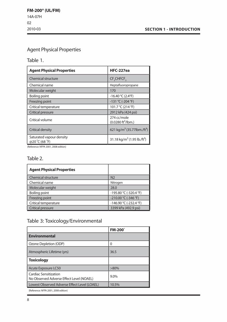
AgentPhysicalProperties
Table1.
Agent Physical Properties HFC-227ea
Chemicalstructure CF3CHFCF3
Chemicalname Heptafluoropropane
Molecularweight 170Boilingpoint -1�.40°C(2.4°F)Freezingpoint -131°C(-204°F)Criticaltemperature 101.7°C(214°F)Criticalpressure 2912kPa(424psi)
Criticalvolume 274cc/mole(0.02�0ft³/lbm.)
Criticaldensity �21kg/m³(3�.77lbm./ft³)
Saturatedvapourdensity@20°C(��°F) 31.1�kg/m³(1.9�lb./ft³)
(Reference:NFPA2001,200�edition)
Table2.
Agent Physical Properties
Chemicalstructure N2Chemicalname Nitrogen
Molecularweight 2�.0Boilingpoint -19�.�0°C(-320.4°F)Freezingpoint -210.00°C(-34�°F)Criticaltemperature -14�.90°C(-232.4°F)Criticalpressure 3399kPa(492.9psi)
Table3:Toxicology/Environmental
FM-200®
Environmental
OzoneDepletion(ODP) 0
AtmosphericLifetime(yrs) 3�.�
Toxicology
AcuteExposureLC�0 >�0%
CardiacSensitizationNoObservedAdverseEffectLevel(NOAEL) 9.0%
LowestObservedAdverseEffectLevel(LOAEL) 10.�%(Reference:NFPA2001,200�edition)
SystemComponentsThis section describes the individual components that comprise a complete system��� Some items are optional depending on the application, and are indicated as such���
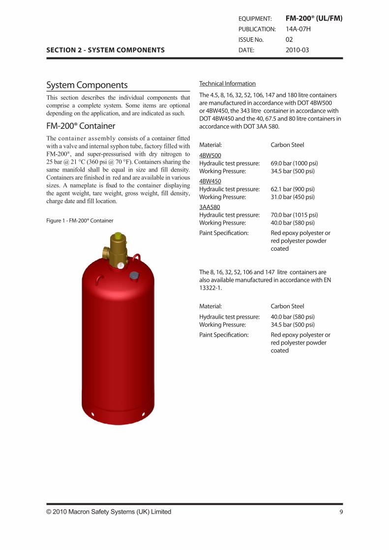
FM-200®ContainerThe container assembly consists of a container fitted with a valve and internal syphon tube, factory filled with FM-200®, and super-pressurised with dry nitrogen to 25 bar @ 21 °C (360 psi @ 70 °F)��� Containers sharing the same manifold shall be equal in size and fill density��� Containers are finished in red and are available in various sizes��� A nameplate is fixed to the container displaying the agent weight, tare weight, gross weight, fill density, charge date and fill location���
Figure1-FM-200®Container
TechnicalInformation
The4.�,�,1�,32,�2,10�,147and1�0litrecontainersaremanufacturedinaccordancewithDOT4BW�00or4BW4�0,the343litrecontainerinaccordancewithDOT4BW4�0andthe40,�7.�and�0litrecontainersinaccordancewithDOT3AA��0.
Material: CarbonSteel
4BW�00Hydraulictestpressure:WorkingPressure:
�9.0bar(1000psi)34.�bar(�00psi)
4BW4�0Hydraulictestpressure:WorkingPressure:
�2.1bar(900psi)31.0bar(4�0psi)
3AA��0Hydraulictestpressure:WorkingPressure:
70.0bar(101�psi)40.0bar(��0psi)
PaintSpecification: Redepoxypolyesterorredpolyesterpowdercoated
The�,1�,32,�2,10�and147litrecontainersarealsoavailablemanufacturedinaccordancewithEN13322-1.
Material: CarbonSteel
Hydraulictestpressure:WorkingPressure:
40.0bar(��0psi)34.�bar(�00psi)
PaintSpecification: Redepoxypolyesterorredpolyesterpowdercoated
9© 2010 Macron Safety Systems (UK) Limited
SECTION 2 - SYSTEM COMPONENTS
EQUIPMENT: FM-200® (UL/FM)PUBLICATION: 14A-07HISSUENo. 02DATE: 2010-03
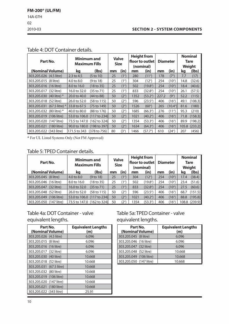
Table�:TPEDContainerdetails.
Table4:DOTContainerdetails.
Part No. Equivalent Lengths(Nominal Volume) (m)
303.20�.02� (4.�litre) �.09�303.20�.01� (�litre) �.09�303.20�.01� (1�litre) �.09�303.20�.017 (32litre) �.09�303.20�.030 (40litre) 10.���303.20�.01� (�2litre) 10.���303.20�.031 (�7.�litre) 10.���303.20�.032 (�0litre) 10.���303.20�.019 (10�litre) 10.���303.20�.020 (147litre) 10.���303.20�.021 (1�0litre) 10.���303.20�.022 (343litre) 2�.91
Part No. Equivalent Lengths(Nominal Volume) (m)
303.20�.04� (�litre) �.09�303.20�.04� (1�litre) �.09�303.20�.047 (32litre) �.09�303.20�.04� (�2litre) 10.���303.20�.049 (10�litre) 10.���303.20�.0�0 (147litre) 10.���
Table4a:DOTContainer-valveequivalentlengths.
Table�a:TPEDContainer-valveequivalentlengths.
10
SECTION 2 - SYSTEM COMPONENTS
* For UL Listed Systems Only (Not FM Approved)
FM-200® (UL/FM)14A-07H022010-03
Part No. Minimum and Maximum Fills
Valve Size
Height from floor to outlet
(nominal)Diameter
Nominal Tare
Weight(Nominal Volume) kg (lbs) mm (in) mm (in) mm (in) kg (lbs)
303.20�.02� (4.�litre) 2.3to4.� (�to10) 2� (1”) 2�0 (11”) 17� (7”) 7.7 (17)303.20�.01� (�litre) 4.0to�.0 (9to1�) 2� (1”) 304 (12”) 2�4 (10”) 14.� (32.�)303.20�.01� (1�litre) �.0to1�.0 (1�to3�) 2� (1”) �02 (19.�”) 2�4 (10”) 1�.4 (40.�)303.20�.017 (32litre) 1�.0to32.0 (3�to71) 2� (1”) �33 (32.�”) 2�4 (10”) 2�.1 (�7.�)303.20�.030 (40litre)* 20.0to40.0 (44to��) �0 (2”) 13�2 (�3.2”) 227.2 (9”) �2.2 (11�)303.20�.01� (�2litre) 2�.0to�2.0 (��to11�) �0 (2”) �9� (23.�”) 40� (1�”) 49.1 (10�.3)303.20�.031 (�7.�litre)* 33.�to�7.� (7�to149) �0 (2”) 1�2� (�0”) 2�� (10.4”) �1.� (1�0)303.20�.032 (�0litre)* 40.0to�0.0 (��to17�) �0 (2”) 1��� (��.3”) 27� (11”) 9�.3 (210)303.20�.019 (10�litre) �3.0to10�.0 (117to234) �0 (2”) 1021 (40.2”) 40� (1�”) 71.� (1��.3)303.20�.020 (147litre) 73.�to147.0 (1�2to324) �0 (2”) 13�4 (�3.3”) 40� (1�”) �9.9 (19�.2)303.20�.021 (1�0litre) 90.0to1�0.0 (19�to397) �0 (2”) 1�34 (�4.3”) 40� (1�”) 10�.� (233.2)303.20�.022 (343litre) 171.�to343 (37�to7��) �0 (3”) 14�� (�7.7”) �10 (24”) 207 (4��)
Part No. Minimum and Maximum Fills
Valve Size
Height from floor to outlet
(nominal)Diameter
Nominal Tare
Weight(Nominal Volume) kg (lbs) mm (in) mm (in) mm (in) kg (lbs)
303.20�.04� (�litre) 4.0to�.0 (9to1�) 2� (1”) 304 (12”) 2�4 (10”) 17.4 (3�.4)303.20�.04� (1�litre) �.0to1�.0 (1�to3�) 2� (1”) �02 (19.�”) 2�4 (10”) 23.4 (�1.�)303.20�.047 (32litre) 1�.0to32.0 (3�to71) 2� (1”) �33 (32.�”) 2�4 (10”) 27.� (�0.�)303.20�.04� (�2litre) 2�.0to�2.0 (��to11�) �0 (2”) �9� (23.�”) 40� (1�”) ��.7 (1�1.�)303.20�.049 (10�litre) �3.0to10�.0 (117to234) �0 (2”) 1021 (40.2”) 40� (1�”) ��.� (19�.�)303.20�.0�0 (147litre) 73.�to147.0 (1�2to324) �0 (2”) 13�4 (�3.3”) 40� (1�”) 10�.� (239.9)

ContainerLabelThe container label details the weight of FM-200®
contained, empty weight, fill density and charge date��� Once the label is applied to the container surface, and to avoid possible tampering it can not be removed intact���
Figure2-ContainerLabel(PartNo.314.20�.021Shown)
TechnicalInformation
Material: Aluminum
Adhesive: Pre-applied3Madhesive94��
Certification: ULRecognised
OverallSize: 241.3mmx1��.1mm(9.�”x�.�”)(PartNo.314.20�.021)(PartNo.314.20�.04�)*
���mmx�0.�mm(22”x2”)(PartNo.314.20�.022)(PartNo.314.20�.04�)*
Weight: 0.041�kg(0.092lbs)(PartNo.314.20�.021)(PartNo.314.20�.04�)*
0.0300kg(0.0��lbs)(PartNo.314.20�.022)(PartNo.314.20�.04�)*
* For UL Listed Systems Only (Not FM Approved)
INSPECTION OF EXTINGUISHING SYSTEM
MONTHLY INSPECTION- EXAMINE PIPING AND NOZZLES TO MAKE CERTAIN
THEY ARE UNOBSTRUCTED- CHECK CONTAINER PRESSURE IF LOSS EXCEEDS 10%
(WHEN ADJUSTED FOR TEMPERATURE), REFILL OR REPLACE CONTAINER.
6-MONTHLY INSPECTION- CHECK AGENT QUANTITY AND PRESSURE. REFILL OR
REPLACE IF A LOSS IN AGENT QUANTITY OF MORE THAN 5% OR A LOSS IN PRESSURE (ADJUSTED FOR TEMPERATURE) OF MORE THAN 10% IS DETERMINED.
REFER TO ENGINEERED SYSTEM INSTALLATIONMANUAL, PART NO. 14a-07H, (AVAILABLE FROMMACRON), AND NFPA 2001, FOR ADDITIONALINSPECTION AND MAINTENANCE INSTRUCTIONS.
THIS SYSTEM IS MADE UP OF UNITS TESTED WITHINLIMITATIONS CONTAINED IN THE DETAILEDINSTRUCTION MANUAL.
THIS SYSTEM SHOULD BE PERIODICALLY INSPECTEDBY TRAINED PERSONNEL. THE SYSTEM DESIGNERMUST BE CONSULTED WHENEVER CHANGES AREPLANNED FOR THE SYSTEM OR AREA OF PROTECTION.
CAUTIONUNCONTROLLED VALVE OPERATION COULD RESULT INSEVERE INJURY OR DEATH TO OPERATORS ORBYSTANDERS, ENSURE SAFETY OUTLET CAP IS INPLACE IF CONTAINER IS DISCONNECTED FROM PIPEWORK. CONTAINERS SHOULD NOT BE POSITIONED INDIRECT SUNLIGHT.
WARNINGTHE DISCHARGE OF CLEAN AGENTSYSTEMS TO EXTINGUISH A FIRECAN RESULT IN A POTENTIALHAZARD TO PERSONNEL FROMTHE NATURAL FORM OF THE CLEANAGENT OR FROM THE PRODUCTSOF COMBUSTION THAT RESULTFROM EXPOSURE OF THE AGENTTO THE FIRE OR HOT SURFACES.UNNECESSARY EXPOSURE OFPERSONNEL EITHER TO THENATURAL AGENT OR TO THEPRODUCTS OF DECOMPOSITIONSHALL BE AVOIDED.CONTACT MACRON IMMEDIATELYAFTER A DISCHARGE OR FIRESITUATION.
RECYCLING PROTECTS THE ENVIRONMENTDO NOT DISPOSE. DISCHARGE ONLY IN CASE OF FIRE. IFCONTAINER CONTENTS MUST BE REMOVED FOR SERVICE.MAINTENANCE OR DISMANTLING OF THE CLEAN AGENTSYSTEM - PRIOR TO REMOVAL, CONTACT YOUR LOCALINSTALLER OR MANUFACTURER FOR INSTRUCTIONS ONHANDLING EQUIPMENT AND ON RECLAIMING OR RECYCLINGCLEAN AGENT.
DO NOT COVER, REMOVE OR DEFACE THIS LABEL
FM-200® HMIS 2-0-0/HEPTAFLUOROPROPANE / SEE WARNINGS ONPRODUCT LABEL / CONTENTS UNDER PRESSURE. NITROGEN EXPELLENTGAS HMIS 0-0-0 / VERY COLD DISCHARGE. CONTENTS UNDER HIGHPRESSURE.
CONSULT DUPONT DE NEMOURS (NEDERLAND) B.V., BAHNHOEKWEG 22,NL-3313 LA DORDRECHT, THE NETHERLANDS. +31-78-630-1011 FORMATERIAL SAFETY DATA SHEET.
THIS CONTAINER IS FILLED WITH FM-200® (HEPTAFLUOROPROPANE) AND IS SUPERPRESSURIZED
TO 25 BAR (360 PSI) AT 21°C (70°F) WITH DRY NITROGEN
PART NO.:
AGENT WEIGHT: KG (lb)
TARE WEIGHT: KG (lb)
GROSS WEIGHT: KG (lb)
FILL DENSITY: KG/L (lb/ft3)
CHARGE DATE:
FILL LOCATION:
THE DATE OF MANUFACTURE IS ON THE CONTAINER
SUITABLE FOR USE IN AMBIENT TEMPERATURES OF 0°C TO 54°C (32°F TO +130°F)
16, 32 AND 52 LITRE CONTAINERS MUST BE TRANSPORTED AND STORED
IN THE VERTICAL POSITION
FACTORY TESTED TWICE DOT SERVICE PRESSURE
STAMPED ON THE CONTAINER
Macron Safety Systems (UK) Ltd., Burlingham House,
Gapton Hall Industrial Estate,Great Yarmouth, Norfolk, NR31 0NN
Tel no. +44 (0)1493 417600Fax no. +44 (0)1493 417700
1S66CLEAN AGENT
FIRE EXTINGUISHING SYSTEM UNIT
11© 2010 Macron Safety Systems (UK) Limited
SECTION 2 - SYSTEM COMPONENTS
EQUIPMENT: FM-200® (UL/FM)PUBLICATION: 14A-07HISSUENo. 02DATE: 2010-03

2�mm(1”)ValveAssemblyPartNo.302.209.001
�0mm(2”)ValveAssemblyPartNo.302.209.002
�0mm(3”)ValveAssemblyPartNo.302.20�.002
Figure3-ValveAssembly
ValveAssemblyThe container valve is the result of extensive research and development and incorporates many unique safety features��� The valve assembly is factory-fitted to the container and is supplied pre-assembled with a low pressure switch (to be ordered seperately), pressure gauge and burst disc���
TechnicalInformation
2�mm(1”)Valve
BodyMaterial: BrassCZ121OutletAnti-RecoilCapMaterial:
CZ122
Max.WorkingPressure: 34bar(493psi)Outlet: 2�mm(1”BSPP)LowPressureSwitchPort: 1/�”NPTGaugePort: 1/�”NPTPilotPressurePort: 1/4”BSPPSolenoidAdaptorPort: 1/�”NPTOverallSize: 130mm(L)x�2mm(Dia)
(�.12”(L)x2.44”(Dia))Weight: 2.9�kg(�.�2�lbs)EquivalentLength: �.09�m(20ft)
�0mm(2”)ValveBodyMaterial: BrassCZ121OutletAnti-RecoilCapMaterial:
CZ122
Max.WorkingPressure: 34bar(493psi)Outlet: �0mm(2”BSPP)LowPressureSwitchPort: 1/�”NPTGaugePort: 1/�”NPTPilotPressurePort: 1/4”BSPPSolenoidAdaptorPort: 1/�”NPTOverallSize: 173mm(L)x100mm(Dia)
(�.12”(L)x3.94”(Dia))Weight: 9.1�kg(20.23�lbs)EquivalentLength: 10.���m(3�ft)
�0mm(3”)ValveMaterial: BrassUNS3�000Max.WorkingPressure: 34bar(493psi)Outlet: �0mm(3”Flared*)LowPressureSwitchPort: 1/�”NPTGaugePort: 1/�”NPTPilotPressurePort: 1/4”NPTSolenoidAdaptorPort: NoneOverallSize: 241mm(L)x129mm(Dia)
(9.�0”(L)x�.0�”(Dia))Weight: 1�.�2kg(41.491lbs)EquivalentLength: 2�.91m(��ft)
*Outletadaptorsareavailablefor3”NPT,BSPandgrooved.
12
SECTION 2 - SYSTEM COMPONENTS
FM-200® (UL/FM)14A-07H022010-03

Figure4-BurstDisc
BurstDiscA burst disc is factory fitted to every valve assembly��� It is designed to rupture when the container becomes over pressurised when subjected to temperatures above the designed storage temperature of the container���
PrincipleofOperationThe FM-200® valve is a high-flow-rate device specially designed for use in fire systems��� Operation is by means of a pressure-differential piston��� Container pressure is used within the valve to create a positive force on the piston, sealing the valve closed��� Operation of the valve occurs when the upper chamber is vented faster than the ‘make up device’ in the shuttle can replace the pressure��� Thereby allowing, the shuttle to be forced up, and free flow of FM-200® from the valve��� Upper chamber pressure is released by the electrical, mechanical or pneumatic actuator���
The valve incorporates the following features:A pressure operated safety release device (burst disc)���
Main outlet, fitted with anti-recoil cap���
A connection for a pneumatic, mechanical or electrical actuator, fitted with safety cap���
A connection for an electrical solenoid���
A connection for the pneumatic actuation port���
•
•
•
•
•
13© 2010 Macron Safety Systems (UK) Limited
SECTION 2 - SYSTEM COMPONENTS
EQUIPMENT: FM-200® (UL/FM)PUBLICATION: 14A-07HISSUENo. 02DATE: 2010-03
BurstDiscfor2�mm(1”)ValvePartNo.2091�
BurstDiscfor�0mm(2”)ValvePartNo.2091�
BurstDiscfor�0mm(3”)ValvePartNo.1�330
TechnicalInformation
2�mm(1”)Valve&�0mm(2”)Valve
Body: BrassCZ121Rating: �3.4bar(774.�psi)@�0°C(122°F)Thread: M1�x1.00HoleOrientation: 90°toBodyTorque: 3�Nm(2�.�Ibs.ft)OverallSize: 20mm(L)x1�mm(Dia)
(0.79”(L)x0.71”(Dia))Weight: 0.02�kg(0.0�2lbs)
�0mm(3”)Valve
Body: BrassUNS-C3�000Rating: �2bar(7�0psi)@�0°C(122°F)Thread: 0.937�-1�UN-3AHoleOrientation: 90°toBodyTorque: ��Nm(�0Ibs.ft)OverallSize: 33.3mm(L)x1�mm(Dia)
(1.312�”(L)x0.71”(Dia))Weight: 0.0��kg(0.19�lbs)
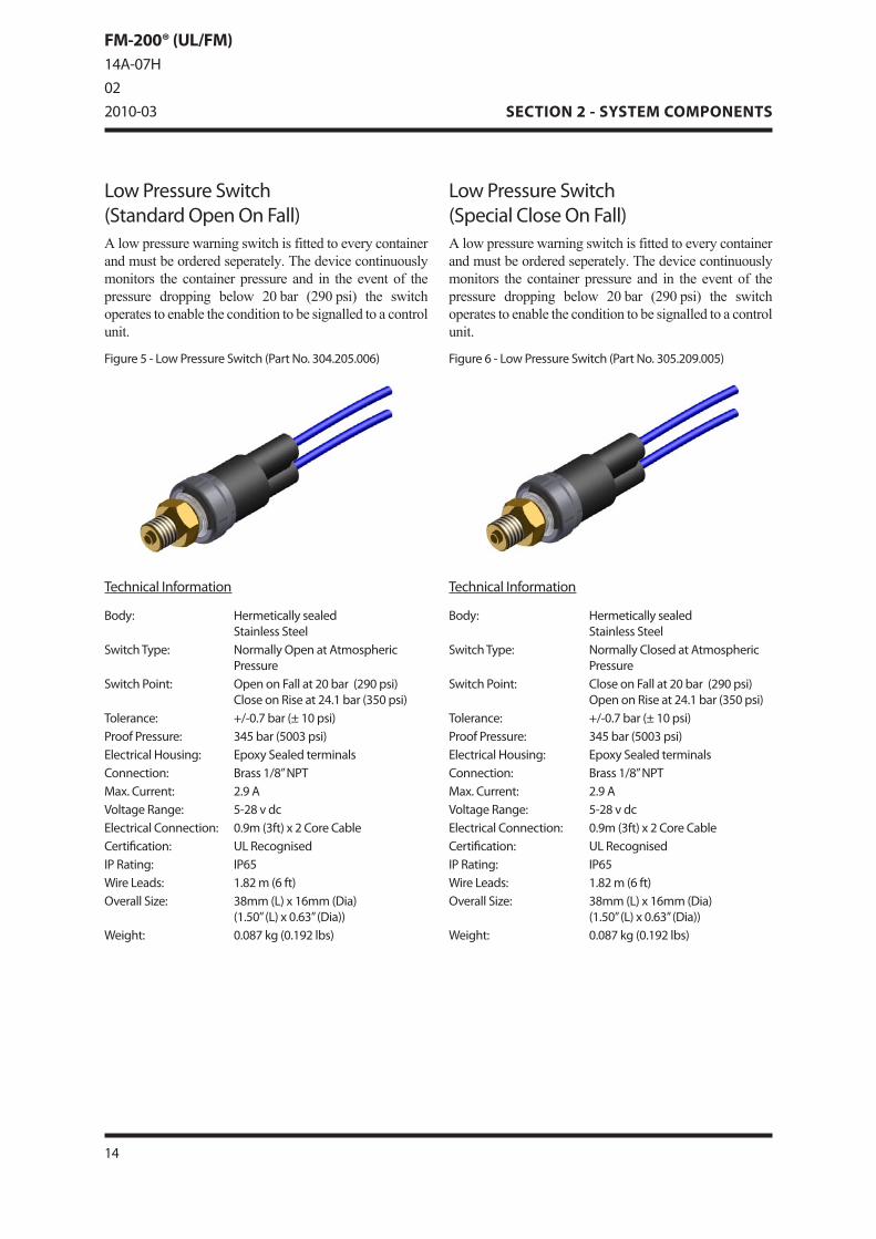
LowPressureSwitch(SpecialCloseOnFall)A low pressure warning switch is fitted to every container and must be ordered seperately��� The device continuously monitors the container pressure and in the event of the pressure dropping below 20 bar (290 psi) the switch operates to enable the condition to be signalled to a control unit���
TechnicalInformation
Body: HermeticallysealedStainlessSteel
SwitchType: NormallyClosedatAtmosphericPressure
SwitchPoint: CloseonFallat20bar(290psi)OpenonRiseat24.1bar(3�0psi)
Tolerance: +/-0.7bar(±10psi)ProofPressure: 34�bar(�003psi)ElectricalHousing: EpoxySealedterminalsConnection: Brass1/�”NPTMax.Current: 2.9AVoltageRange: �-2�vdcElectricalConnection: 0.9m(3ft)x2CoreCableCertification: ULRecognisedIPRating: IP��WireLeads: 1.�2m(�ft)OverallSize: 3�mm(L)x1�mm(Dia)
(1.�0”(L)x0.�3”(Dia))Weight: 0.0�7kg(0.192lbs)
Figure�-LowPressureSwitch(PartNo.30�.209.00�)
LowPressureSwitch(StandardOpenOnFall)A low pressure warning switch is fitted to every container and must be ordered seperately��� The device continuously monitors the container pressure and in the event of the pressure dropping below 20 bar (290 psi) the switch operates to enable the condition to be signalled to a control unit���
TechnicalInformation
Body: HermeticallysealedStainlessSteel
SwitchType: NormallyOpenatAtmosphericPressure
SwitchPoint: OpenonFallat20bar(290psi)CloseonRiseat24.1bar(3�0psi)
Tolerance: +/-0.7bar(±10psi)ProofPressure: 34�bar(�003psi)ElectricalHousing: EpoxySealedterminalsConnection: Brass1/�”NPTMax.Current: 2.9AVoltageRange: �-2�vdcElectricalConnection: 0.9m(3ft)x2CoreCableCertification: ULRecognisedIPRating: IP��WireLeads: 1.�2m(�ft)OverallSize: 3�mm(L)x1�mm(Dia)
(1.�0”(L)x0.�3”(Dia))Weight: 0.0�7kg(0.192lbs)
Figure�-LowPressureSwitch(PartNo.304.20�.00�)
14
SECTION 2 - SYSTEM COMPONENTS
FM-200® (UL/FM)14A-07H022010-03
1�© 2010 Macron Safety Systems (UK) Limited
SECTION 2 - SYSTEM COMPONENTS
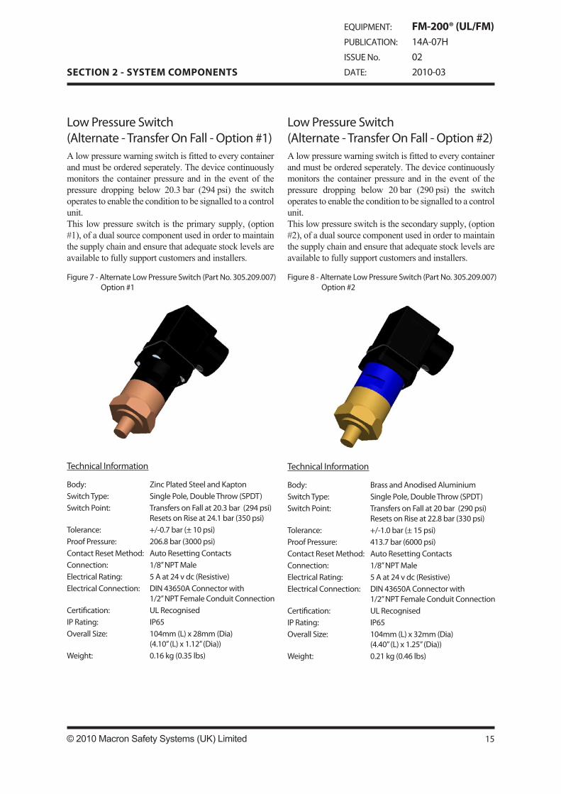
LowPressureSwitch(Alternate-TransferOnFall-Option#1)A low pressure warning switch is fitted to every container and must be ordered seperately��� The device continuously monitors the container pressure and in the event of the pressure dropping below 20���3 bar (294 psi) the switch operates to enable the condition to be signalled to a control unit���This low pressure switch is the primary supply, (option #1), of a dual source component used in order to maintain the supply chain and ensure that adequate stock levels are available to fully support customers and installers���
LowPressureSwitch(Alternate-TransferOnFall-Option#2)A low pressure warning switch is fitted to every container and must be ordered seperately��� The device continuously monitors the container pressure and in the event of the pressure dropping below 20 bar (290 psi) the switch operates to enable the condition to be signalled to a control unit���This low pressure switch is the secondary supply, (option #2), of a dual source component used in order to maintain the supply chain and ensure that adequate stock levels are available to fully support customers and installers���
Figure7-AlternateLowPressureSwitch(PartNo.30�.209.007) Option#1
Figure�-AlternateLowPressureSwitch(PartNo.30�.209.007) Option#2
TechnicalInformation
Body: ZincPlatedSteelandKaptonSwitchType: SinglePole,DoubleThrow(SPDT)SwitchPoint: TransfersonFallat20.3bar(294psi)
ResetsonRiseat24.1bar(3�0psi)Tolerance: +/-0.7bar(±10psi)ProofPressure: 20�.�bar(3000psi)ContactResetMethod: AutoResettingContactsConnection: 1/�”NPTMaleElectricalRating: �Aat24vdc(Resistive)ElectricalConnection: DIN43��0AConnectorwith
1/2”NPTFemaleConduitConnectionCertification: ULRecognisedIPRating: IP��OverallSize: 104mm(L)x2�mm(Dia)
(4.10”(L)x1.12”(Dia))Weight: 0.1�kg(0.3�lbs)
TechnicalInformation
Body: BrassandAnodisedAluminiumSwitchType: SinglePole,DoubleThrow(SPDT)SwitchPoint: TransfersonFallat20bar(290psi)
ResetsonRiseat22.�bar(330psi)Tolerance: +/-1.0bar(±1�psi)ProofPressure: 413.7bar(�000psi)ContactResetMethod: AutoResettingContactsConnection: 1/�”NPTMaleElectricalRating: �Aat24vdc(Resistive)ElectricalConnection: DIN43��0AConnectorwith
1/2”NPTFemaleConduitConnectionCertification: ULRecognisedIPRating: IP��OverallSize: 104mm(L)x32mm(Dia)
(4.40”(L)x1.2�”(Dia))Weight: 0.21kg(0.4�lbs)
EQUIPMENT: FM-200® (UL/FM)PUBLICATION: 14A-07HISSUENo. 02DATE: 2010-03

FixingBracketsThe bracket assembly consists of one back channel and a nut and bolt with two bracket half straps��� To securely hold the container in position during the system discharge, two bracket assemblies are required per container��� The only exceptions are the 4���5 and 8 litre containers which only require one���
Each strap is notched for insertion into the back channel allowing the container to be properly aligned��� The bracket assembly is designed to be mounted to a rigid vertical surface with the container assembly resting fully on the floor���
Figure9-FixingBracket(StrapStyle)
TechnicalInformation
Material: MildSteelCoating: BlackPolyethylenepowder-PlascoatLDPEMounting: UnistrutChannelWeight: 0.34kg(0.7�lbs)(PartNo.311.20�.020)
0.30kg(0.��lbs)(PartNo.311.20�.013)0.4�kg(1.01lbs)(PartNo.311.20�.014)0.2�kg(0.�2lbs)(PartNo.311.20�.021)0.30kg(0.��lbs)(PartNo.311.20�.017)0.34kg(0.7�lbs)(PartNo.311.20�.01�)0.71kg(1.��lbs)(PartNo.311.20�.019)
Part Number Container Size Length of Back Channel
mm (in)311.20�.020 4.�litre
17�mmdia.(7”)400(1�.7�”)
311.20�.013 �,1�,32litre2�4mmdia.(10”)
�00(19.�9”)
311.20�.014 �2,10�,147,1�0litre40�mmdia.(1�”)
�00(23.�”)
311.20�.021* 40litre(Seamless)227mmdia.(9”)
400(1�.7�”)
311.20�.017* �7.�litre(Seamless)2��mmdia.(10.4”)
400(1�.7�”)
311.20�.01�* �0litre(Seamless)27�mmdia.(11”)
400(1�.7�”)
311.20�.019 343litre�10mmdia.(24”)
�93(27.3”)
* For UL Listed Systems Only (Not FM Approved)
1�
SECTION 2 - SYSTEM COMPONENTS
FM-200® (UL/FM)14A-07H022010-03
TechnicalInformation
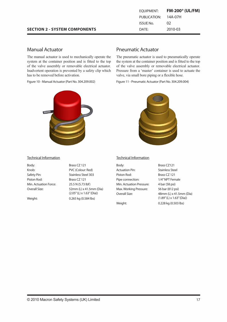
Body: BrassCZ121ActuationPin: StainlessSteelPistonRod: BrassCZ121Pipeconnection: 1/4”NPTFemaleMin.ActuationPressure: 4bar(��psi)Max.WorkingPressure: ��bar(�12psi)OverallSize: 4�mm(L)x41.�mm(Dia)
(1.�9”(L)x1.�3”(Dia))
Weight: 0.22�kg(0.�03lbs)
Figure11-PneumaticActuator(PartNo.304.209.004)
PneumaticActuatorThe pneumatic actuator is used to pneumatically operate the system at the container position and is fitted to the top of the valve assembly or removable electrical actuator��� Pressure from a ‘master’ container is used to actuate the valve, via small bore piping or a flexible hose���
TechnicalInformation
Body: BrassCZ121Knob: PVC(Colour:Red)SafetyPin: StainlessSteel303PistonRod: BrassCZ121Min.ActuationForce: 2�.�N(�.73Ibf)OverallSize: �2mm(L)x41.�mm(Dia)
(2.0�”(L)x1.�3”(Dia))
Weight: 0.2��kg(0.��4lbs)
ManualActuatorThe manual actuator is used to mechanically operate the system at the container position and is fitted to the top of the valve assembly or removable electrical actuator��� Inadvertent operation is prevented by a safety clip which has to be removed before activation���
Figure10-ManualActuator(PartNo.304.209.002)
17© 2010 Macron Safety Systems (UK) Limited
SECTION 2 - SYSTEM COMPONENTS
EQUIPMENT: FM-200® (UL/FM)PUBLICATION: 14A-07HISSUENo. 02DATE: 2010-03

Figure13-ElectricalActuator-BridgeRectifier(PartNo.304.209.001)
RemovableElectricalActuator(BridgeRectifier)The removable electrical actuator locates to the top of the container valve��� 24 v dc is required for solenoid operation��� Provision is made for the connection of a manual actuator to the top of the actuator assembly��� Due to the design of the bridge rectifier it will operate regardless of how it is wired up; the positive supply from control panel can be connected to either terminal 1 or 2 with the reverse for the negative supply��� The removable electrical actuator has a life span of 10 years from manufacture, which is indicated on the label���
TechnicalInformation
Body: MildSteel&DullNickelSwivelnut: BrassCZ121ActuationPin: StainlessSteelActuationType: LatchingResetRequirement: ManuallyviaResetTool
suppliedConnection: 1”BSPPBrassNominalVoltage: 24vdcNominalCurrent: 0.2�AMax.MonitoringCurrent: 2�mAManualActuationForce: �0N(11.24Ibf)NominalPinTravel: 4.4mm(0.17”)Electricalconnection: 3-pinplugconnectorBackEMFProtection: BridgeRectifierCertification: ULRecognisedOverallSize: 104mm(L)x44mm(Dia)
(4.09”(L)x1.73”(Dia))Weight: 0.9�kg(2.09lbs)
TechnicalInformation
Body: MildSteel&DullNickelSwivelnut: BrassCZ121ActuationPin: StainlessSteelActuationType: LatchingResetRequirement: ManuallyviaResetTool
suppliedConnection: 1”BSPPBrassNominalVoltage: 24vdcNominalCurrent: 0.2�AMax.MonitoringCurrent: 2�mAManualActuationForce: �0N(11.24Ibf)NominalPinTravel: 4.4mm(0.17”)Electricalconnection: 3-pinplugconnectorBackEMFProtection: SuppressionDiodeCertification: ULRecognisedOverallSize: 104mm(L)x44mm(Dia)
(4.09”(L)x1.73”(Dia))Weight: 0.9�kg(2.09lbs)
Figure12-ElectricalActuator-SuppressionDiode(PartNo.304.20�.010)
RemovableElectricalActuator(SuppressionDiode)The removable electrical actuator locates to the top of the container valve��� 24 v dc is required for solenoid operation��� Provision is made for the connection of a manual actuator to the top of the actuator assembly��� The suppression diode electrical actuator must be wired up correctly with the positive supply from the control panel connected to terminal 1, and the negative supply connected to terminal 2���The removable electrical actuator has a life span of 10 years from manufacture, which is indicated on the label���
1�
SECTION 2 - SYSTEM COMPONENTS
FM-200® (UL/FM)14A-07H022010-03
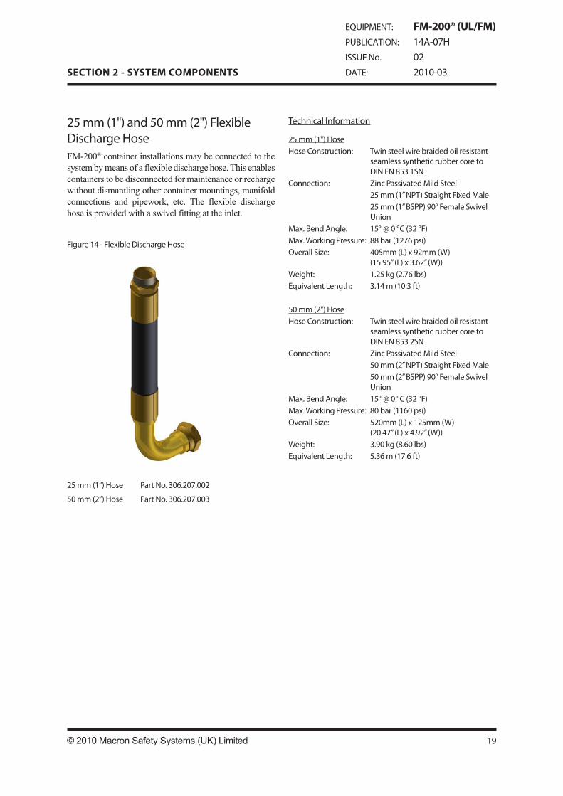
2�mm(1")and�0mm(2")FlexibleDischargeHoseFM-200® container installations may be connected to the system by means of a flexible discharge hose��� This enables containers to be disconnected for maintenance or recharge without dismantling other container mountings, manifold connections and pipework, etc��� The flexible discharge hose is provided with a swivel fitting at the inlet���
TechnicalInformation
2�mm(1")HoseHoseConstruction: Twinsteelwirebraidedoilresistant
seamlesssyntheticrubbercoretoDINEN��31SN
Connection: ZincPassivatedMildSteel2�mm(1”NPT)StraightFixedMale2�mm(1”BSPP)90°FemaleSwivelUnion
Max.BendAngle: 1�°@0°C(32°F)Max.WorkingPressure: ��bar(127�psi)OverallSize: 40�mm(L)x92mm(W)
(1�.9�”(L)x3.�2”(W))Weight: 1.2�kg(2.7�lbs)EquivalentLength: 3.14m(10.3ft)
�0mm(2")HoseHoseConstruction: Twinsteelwirebraidedoilresistant
seamlesssyntheticrubbercoretoDINEN��32SN
Connection: ZincPassivatedMildSteel�0mm(2”NPT)StraightFixedMale�0mm(2”BSPP)90°FemaleSwivelUnion
Max.BendAngle: 1�°@0°C(32°F)Max.WorkingPressure: �0bar(11�0psi)OverallSize: �20mm(L)x12�mm(W)
(20.47”(L)x4.92”(W))Weight: 3.90kg(�.�0lbs)EquivalentLength: �.3�m(17.�ft)
Figure14-FlexibleDischargeHose
2�mm(1”)Hose PartNo.30�.207.002
�0mm(2”)Hose PartNo.30�.207.003
19© 2010 Macron Safety Systems (UK) Limited
SECTION 2 - SYSTEM COMPONENTS
EQUIPMENT: FM-200® (UL/FM)PUBLICATION: 14A-07HISSUENo. 02DATE: 2010-03

Figure1�-�0mm(3")DischargeHose(PartNo.30�.20�.00�)
�0mm(3”)DischargeHoseThe discharge hose is used with the 3” NPT single tank adaptor and 90° elbow to connect the container valve outlet to the distribution piping in single tank systems��� The hose is constructed of corrugated stainless steel tubing with stainless braid cover���
TechnicalInformation
HoseConstruction: DoublebraidstainlesssteelMax.WorkingPressure: 3�bar(�07.�psi)Min.BendRadius: 4�0mm(1�”)OverallSize: 40�mm(L)x7�mm(Dia)
(1�.9�”(L)x2.99”(Dia))Weight: 3.00kg(�.�1lbs)EquivalentLength: 1.��m(�.1ft)
TechnicalInformation
Hose: DoublebraidstainlesssteelElbow: StainlesssteelUNS30400ValveSwivelNut: StainlesssteelUNS30400CheckValveSwivelNut: CadmiumplatedmildsteelCheckValveBody: CadmiumplatedmildsteelCheckValveSealandSeat: BrassUNS3�000Spring: Stainlesssteel2.�4kg(�.27
lbs)Max.WorkingPressure: 3�bar(�07.�psi)OverallSize(MinusCheckValve):
�19mm(L)x2�4mm(W)(24.37”(L)x10.00”(W))
Weight: 20.�0kg(4�.20lbs)EquivalentLength: 1�.��m(�2ft)
�0mm(3”)DischargeHose/CheckValveAssemblyThe discharge hose/check valve assembly combines the elbow, hose, check valve, and swivel coupling for connection to the valve discharge outlet and the discharge manifold��� The check valve provides the facility for a 40 mm (1½”) height adjustment���
Figure1�-�0mm(3")DischargeHose/CheckValveAssembly(PartNo.30�.20�.00�)
20
SECTION 2 - SYSTEM COMPONENTS
FM-200® (UL/FM)14A-07H022010-03
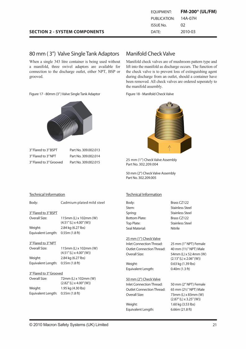
ManifoldCheckValveManifold check valves are of mushroom pattern type and lift into the manifold as discharge occurs��� The function of the check valve is to prevent loss of extinguishing agent during discharge from an outlet, should a container have been removed��� All check valves are ordered seperately to the manifold assembly���
TechnicalInformation
Body: BrassCZ122Stem: StainlessSteelSpring: StainlessSteelBottomPlate: BrassCZ122TopPlate: StainlessSteelSealMaterial: Nitrile
2�mm(1")CheckValveInletConnectionThread: 2�mm(1"NPT)FemaleOutletConnectionThread: 40mm(1½"NPT)MaleOverallSize: �4mm(L)x�2.4mm(W)
(2.13”(L)x2.0�”(W))Weight: 0.�3kg(1.39lbs)EquivalentLength: 0.40m(1.3ft)
�0mm(2")CheckValveInletConnectionThread: �0mm(2"NPT)FemaleOutletConnectionThread: ��mm(2½"NPT)MaleOverallSize: 73mm(L)x�3mm(W)
(2.�7”(L)x3.2�”(W))Weight: 1.�0kg(3.�3lbs)EquivalentLength: �.��m(21.�ft)
Figure1�-ManifoldCheckValveFigure17-�0mm(3”)ValveSingleTankAdaptor
�0mm(3”)ValveSingleTankAdaptorsWhen a single 343 litre container is being used without a manifold, three swivel adaptors are available for connection to the discharge outlet, either NPT, BSP or grooved���
TechnicalInformation
Body: Cadmiumplatedmildsteel
3”Flaredto3”BSPTOverallSize: 11�mm(L)x102mm(W)
(4.�1”(L)x4.00”(W))Weight: 2.�4kg(�.27lbs)EquivalentLength: 0.��m(1.�ft)
3”Flaredto3”NPTOverallSize: 11�mm(L)x102mm(W)
(4.�1”(L)x4.00”(W))Weight: 2.�4kg(�.27lbs)EquivalentLength: 0.��m(1.�ft)
3”Flaredto3”GroovedOverallSize: 72mm(L)x102mm(W)
(2.�2”(L)x4.00”(W))Weight: 1.9�kg(4.30lbs)EquivalentLength: 0.��m(1.�ft)
3”Flaredto3”BSPT PartNo.309.002.013
3”Flaredto3”NPT PartNo.309.002.014
3”Flaredto3”Grooved PartNo.309.002.01�2�mm(1”)CheckValveAssemblyPartNo.302.209.004
�0mm(2”)CheckValveAssemblyPartNo.302.209.00�
21© 2010 Macron Safety Systems (UK) Limited
SECTION 2 - SYSTEM COMPONENTS
EQUIPMENT: FM-200® (UL/FM)PUBLICATION: 14A-07HISSUENo. 02DATE: 2010-03

ManifoldManifolds are fabricated sections of steel pipework��� They enable multiple containers to be connected to a common pipe network��� They may also be used in systems where main / reserve containers arrangements are required���
TechnicalInformation
Material: ASTMA10�GrB/BS3�01Schedule�0Inlet: NPTsocketOutlet: BSPTaper/NPTTaper/�”FlangeTestPress. 90bar(130�psi)Finish: Primed,Readytopaintonsite.
Figure19-TypicalManifoldAssembly
Table�:Manifolds
Note: Assembliesdonotincludecheckvalvesandendcaps. For343litremanifoldsthecheckvalvesarepartofthehose.
Part No.
No. of Inlets
Manifold Pipe Size
Inlet to End Cap Distance
Inlet to Inlet
Distance
Inlet to End Connection
Distance
Container Size
Overall Length
End Thread Connection
mm mm mm mm307.209.022 2 ��mm(2.�”) 1�0(�”) 3�0(14”) 1�0(�”) 4.�Lto32L ��0(2�.�”) BSPT307.209.023 3 ��mm(2.�”) 1�0(�”) 3�0(14”) 1�0(�”) 4.�Lto32L 1000(39.4”) BSPT307.209.024 4 ��mm(2.�”) 1�0(�”) 3�0(14”) 1�0(�”) 4.�Lto32L 13�0(�3.1”) BSPT307.209.001 2 ��mm(2.�”) 1�0(�”) 3�0(14”) 1�0(�”) 4.�Lto32L ��0(2�.�”) NPT307.209.002 3 ��mm(2.�”) 1�0(�”) 3�0(14”) 1�0(�”) 4.�Lto32L 1000(39.4”) NPT307.209.003 4 ��mm(2.�”) 1�0(�”) 3�0(14”) 1�0(�”) 4.�Lto32L 13�0(�3.1”) NPT307.209.02� 2 �0mm(3”) 1�0(�”) �0�(20”) 1�0(�”) �2Lto1�0L �0�(31.�”) BSPT307.209.02� 3 �0mm(3”) 1�0(�”) �0�(20”) 1�0(�”) �2Lto1�0L 131�(�1.�”) BSPT307.209.027 4 �0mm(3”) 1�0(�”) �0�(20”) 1�0(�”) �2Lto1�0L 1�24(71.�”) BSPT307.209.02� � �0mm(3”) 1�0(�”) �0�(20”) 1�0(�”) �2Lto1�0L 2332(91.�”) BSPT307.209.029 � �0mm(3”) 1�0(�”) �0�(20”) 1�0(�”) �2Lto1�0L 2�40(111.�”) BSPT307.209.004 2 �0mm(3”) 1�0(�”) �0�(20”) 1�0(�”) �2Lto1�0L �0�(31.�”) NPT307.209.00� 3 �0mm(3”) 1�0(�”) �0�(20”) 1�0(�”) �2Lto1�0L 131�(�1.�”) NPT307.209.00� 4 �0mm(3”) 1�0(�”) �0�(20”) 1�0(�”) �2Lto1�0L 1�24(71.�”) NPT307.209.007 � �0mm(3”) 1�0(�”) �0�(20”) 1�0(�”) �2Lto1�0L 2332(91.�”) NPT307.209.00� � �0mm(3”) 1�0(�”) �0�(20”) 1�0(�”) �2Lto1�0L 2�40(111.�”) NPT
22
SECTION 2 - SYSTEM COMPONENTS
FM-200® (UL/FM)14A-07H022010-03
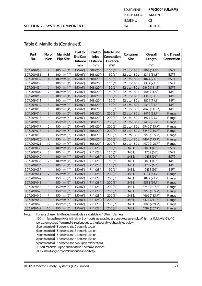
Table�:Manifolds(Continued)
Note: Foreaseofassemblyflangedmanifoldsareavailablefor1�0mmdiameter. 1�0mmflangedmanifoldswitheither3or4portsaresuppliedasaonepieceassembly.Whilstmanifoldswith�to10 portsaremadeupfromsmallersectionsduetothesizeandweightaslistedbelow: �portmanifold-3portendand2portmidsection �portmanifold-3portendand3portmidsection 7portmanifold-3portendand2portmidsection �portmanifold-4portendand3portmidsection 9portmanifold-3portendandtwo3portmidsections 10portmanifold-4portendandtwo3portmidsections All1�0mmflangedmanifoldsincludeanendcap.
Part No.
No. of Inlets
Manifold Pipe Size
Inlet to End Cap Distance
Inlet to Inlet
Distance
Inlet to End Connection
Distance
Container Size
Overall Length
End Thread Connection
mm mm mm mm307.209.030 2 100mm(4”) 1�0(�”) �0�(20”) 1�0(�”) �2Lto1�0L �0�(31.�”) BSPT307.209.031 3 100mm(4”) 1�0(�”) �0�(20”) 1�0(�”) �2Lto1�0L 131�(�1.�”) BSPT307.209.032 4 100mm(4”) 1�0(�”) �0�(20”) 1�0(�”) �2Lto1�0L 1�24(71.�”) BSPT307.209.033 � 100mm(4”) 1�0(�”) �0�(20”) 1�0(�”) �2Lto1�0L 2332(91.�”) BSPT307.209.034 � 100mm(4”) 1�0(�”) �0�(20”) 1�0(�”) �2Lto1�0L 2�40(111.�”) BSPT307.209.009 2 100mm(4”) 1�0(�”) �0�(20”) 1�0(�”) �2Lto1�0L �0�(31.�”) NPT307.209.010 3 100mm(4”) 1�0(�”) �0�(20”) 1�0(�”) �2Lto1�0L 131�(�1.�”) NPT307.209.011 4 100mm(4”) 1�0(�”) �0�(20”) 1�0(�”) �2Lto1�0L 1�24(71.�”) NPT307.209.012 � 100mm(4”) 1�0(�”) �0�(20”) 1�0(�”) �2Lto1�0L 2332(91.�”) NPT307.209.013 � 100mm(4”) 1�0(�”) �0�(20”) 1�0(�”) �2Lto1�0L 2�40(111.�”) NPT307.209.014 3 1�0mm(�”) 1�0(�”) �0�(20”) 200(�”) �2Lto1�0L 141�(��.7”) Flange307.209.01� 4 1�0mm(�”) 1�0(�”) �0�(20”) 200(�”) �2Lto1�0L 1924(7�.7”) Flange307.209.01� � 1�0mm(�”) 1�0(�”) �0�(20”) 200(�”) �2Lto1�0L 2432(9�.7”) Flange307.209.017 � 1�0mm(�”) 1�0(�”) �0�(20”) 200(�”) �2Lto1�0L 2940(11�.7”) Flange307.209.01� 7 1�0mm(�”) 1�0(�”) �0�(20”) 200(�”) �2Lto1�0L 344�(13�.7”) Flange307.209.019 � 1�0mm(�”) 1�0(�”) �0�(20”) 200(�”) �2Lto1�0L 39��(1��.7”) Flange307.209.020 9 1�0mm(�”) 1�0(�”) �0�(20”) 200(�”) �2Lto1�0L 44�4(17�.7”) Flange307.209.021 10 1�0mm(�”) 1�0(�”) �0�(20”) 200(�”) �2Lto1�0L 4972(19�.7”) Flange307.209.03� 2 100mm(4”) 1�0(�”) 711(2�”) 1�0(�”) 343L 1011(40”) BSPT307.209.039 3 100mm(4”) 1�0(�”) 711(2�”) 1�0(�”) 343L 1722(��”) BSPT307.209.040 4 100mm(4”) 1�0(�”) 711(2�”) 1�0(�”) 343L 2433(9�”) BSPT307.209.03� 2 100mm(4”) 1�0(�”) 711(2�”) 1�0(�”) 343L 1011(40”) NPT307.209.03� 3 100mm(4”) 1�0(�”) 711(2�”) 1�0(�”) 343L 1722(��”) NPT307.209.037 4 100mm(4”) 1�0(�”) 711(2�”) 1�0(�”) 343L 2433(9�”) NPT307.209.041 2 1�0mm(�”) 1�0(�”) 711(2�”) 200(�”) 343L 1111(43.7”) Flange307.209.042 3 1�0mm(�”) 1�0(�”) 711(2�”) 200(�”) 343L 1�22(71.7”) Flange307.209.043 4 1�0mm(�”) 1�0(�”) 711(2�”) 200(�”) 343L 2�33(99.7”) Flange307.209.044 � 1�0mm(�”) 1�0(�”) 711(2�”) 200(�”) 343L 3244(127.7”) Flange307.209.04� � 1�0mm(�”) 1�0(�”) 711(2�”) 200(�”) 343L 39��(1��.7”) Flange307.209.04� 7 1�0mm(�”) 1�0(�”) 711(2�”) 200(�”) 343L 4���(1�3.7”) Flange307.209.047 � 1�0mm(�”) 1�0(�”) 711(2�”) 200(�”) 343L �377(211.7”) Flange307.209.04� 9 1�0mm(�”) 1�0(�”) 711(2�”) 200(�”) 343L �0��(239.7”) Flange307.209.049 10 1�0mm(�”) 1�0(�”) 711(2�”) 200(�”) 343L �799(2�7.7”) Flange
23© 2010 Macron Safety Systems (UK) Limited
SECTION 2 - SYSTEM COMPONENTS
EQUIPMENT: FM-200® (UL/FM)PUBLICATION: 14A-07HISSUENo. 02DATE: 2010-03

ManifoldInlets(Sockets)Manifold inlets are available for the construction of system manifolds���
Figure20-ThreadedInletforManifolds.
Table7:ManifoldInlets
TechnicalInformation
Material: CarbonSteeltoASTMA10�/ASTMA3�0LF2
Dimensions: ANSIB1�.11/BS3799PressureRating: 3000lb
24
SECTION 2 - SYSTEM COMPONENTS
FM-200® (UL/FM)14A-07H022010-03
Part No. Manifold Pipe Size
Container Size
Overall Diameter
Thread Connection
Overall Height Weight
mm mm kg1703� ��mm(2½”) 4.�Lto32L 7�dia.(2.9�”) 1½in.NPT 44(1.73”) 0.71(1.�7lbs)
17037 �0mm(3”) �2Lto1�0L 100dia.(3.94”) 2½in.NPT �3(2.4�”) 1.20(2.��lbs)
1703� 100mm(4”) �2Lto1�0L 100dia.(3.94”) 2½in.NPT �3(2.4�”) 1.�2(3.3�lbs)
174�7 1�0mm(�”) �2Lto1�0L 100dia.(3.94”) 2½in.NPT �3(2.4�”) 1.�4(3.40lbs)
1�332 100mm(4”) 343L 122dia.(4.�0”) 3in.NPT 70(2.7�”) 2.0�(4.�2lbs)
1�333 1�0mm(�”) 343L 122dia.(4.�0”) 3in.NPT �3(2.4�”) 1.�3(3.37lbs)

ConstructionofManifoldsFor customers wishing to manufacture their own manifolds they must be constructed as detailed below, and use the manifold inlets specified on Page 24, (Figure 20 and Table 7)���
Figure21-Manifoldconstruction
- PIPING MUST BE SCHEDULE 80- TEST PRESSURE - 90 BAR (1300 psi)- ALL DIMENSIONS MUST BE WITHIN± 1/8”- AFTER WELDING, MAKE CERTAIN ALL INLET HOLES IN THE PIPE ARE CLEAN OF ANY WELD SPATTER AND OPEN COMPLETELY
Table�:Manifolds
2�© 2010 Macron Safety Systems (UK) Limited
SECTION 2 - SYSTEM COMPONENTS
EQUIPMENT: FM-200® (UL/FM)PUBLICATION: 14A-07HISSUENo. 02DATE: 2010-03
No. of Inlets
End Connection
Overall Length
Inlet to End Cap Distance
Inlet to Inlet
Distance
Container Size
Socket Part No.
mm mm mm2 2½in.BSPT/2½in.NPT ��0(2�.�”) 1�0(�”) 3�0(14”) 4.�Lto32L 1703�3 2½in.BSPT/2½in.NPT 1000(39.4”) 1�0(�”) 3�0(14”) 4.�Lto32L 1703�4 2½in.BSPT/2½in.NPT 13�0(�3.1”) 1�0(�”) 3�0(14”) 4.�Lto32L 1703�2 3in.BSPT/3in.NPT �0�(31.�”) 1�0(�”) �0�(20”) �2Lto1�0L 170373 3in.BSPT/3in.NPT 131�(�1.�”) 1�0(�”) �0�(20”) �2Lto1�0L 170374 3in.BSPT/3in.NPT 1�24(71.�”) 1�0(�”) �0�(20”) �2Lto1�0L 17037� 3in.BSPT/3in.NPT 2332(91.�”) 1�0(�”) �0�(20”) �2Lto1�0L 17037� 3in.BSPT/3in.NPT 2�40(111.�”) 1�0(�”) �0�(20”) �2Lto1�0L 170372 4in.BSPT/4in.NPT �0�(31.�”) 1�0(�”) �0�(20”) �2Lto1�0L 1703�3 4in.BSPT/4in.NPT 131�(�1.�”) 1�0(�”) �0�(20”) �2Lto1�0L 1703�4 4in.BSPT/4in.NPT 1�24(71.�”) 1�0(�”) �0�(20”) �2Lto1�0L 1703�� 4in.BSPT/4in.NPT 2332(91.�”) 1�0(�”) �0�(20”) �2Lto1�0L 1703�� 4in.BSPT/4in.NPT 2�40(111.�”) 1�0(�”) �0�(20”) �2Lto1�0L 1703�3 �in.Flange 13��(�3.�”) 1�0(�”) �0�(20”) �2Lto1�0L 174�74 �in.Flange 1�74(73.�”) 1�0(�”) �0�(20”) �2Lto1�0L 174�7� �in.Flange 23�2(93.�”) 1�0(�”) �0�(20”) �2Lto1�0L 174�7� �in.Flange 2�90(113.�”) 1�0(�”) �0�(20”) �2Lto1�0L 174�77 �in.Flange 339�(133.�”) 1�0(�”) �0�(20”) �2Lto1�0L 174�7� �in.Flange 390�(1�3.�”) 1�0(�”) �0�(20”) �2Lto1�0L 174�79 �in.Flange 4414(173.�”) 1�0(�”) �0�(20”) �2Lto1�0L 174�7
10 �in.Flange 4922(193.�”) 1�0(�”) �0�(20”) �2Lto1�0L 174�7

Table�:Manifolds(Continued)
2�
SECTION 2 - SYSTEM COMPONENTS
FM-200® (UL/FM)14A-07H022010-03
No. of Inlets
End Connection
Overall Length
Inlet to End Cap Distance
Inlet to Inlet
Distance
Container Size
Socket Part No.
mm mm mm2 4in.BSPT/4in.NPT 1011(40”) 1�0(�”) 711(2�”) 343L 1�3323 4in.BSPT/4in.NPT 1722(��”) 1�0(�”) 711(2�”) 343L 1�3324 4in.BSPT/4in.NPT 2433(9�”) 1�0(�”) 711(2�”) 343L 1�3322 �in.Flange 10�1(42”) 1�0(�”) 711(2�”) 343L 1�3333 �in.Flange 1772(70”) 1�0(�”) 711(2�”) 343L 1�3334 �in.Flange 24�3(9�”) 1�0(�”) 711(2�”) 343L 1�333� �in.Flange 3192(12�”) 1�0(�”) 711(2�”) 343L 1�333� �in.Flange 390�(1�4”) 1�0(�”) 711(2�”) 343L 1�3337 �in.Flange 4�1�(1�2”) 1�0(�”) 711(2�”) 343L 1�333� �in.Flange �327(210”) 1�0(�”) 711(2�”) 343L 1�3339 �in.Flange �03�(23�”) 1�0(�”) 711(2�”) 343L 1�333
10 �in.Flange �749(2��”) 1�0(�”) 711(2�”) 343L 1�333

ManifoldBracketAssemblyA manifold bracket assembly consists of two lengths of unistrut, mounted vertically on a wall or bulk head to enable height adjustment of the manifold assembly��� Cantilever brackets are fastened to the unistrut and each are held in position using a uninut long spring, washer and hex head screw��� Manifold brackets slot into the cantilever and are clamped using a hex head screw and plain nut��� Each manifold bracket assembly is supplied in pairs���
Figure22-ManifoldBracket
FlexiblePilotHoseThe flexible pilot hose is used to connect pressure activated devices to the system, e���g��� the pilot cylinder to the slave container to the pressure switch���
Figure23-Flexiblehose(PartNo.30�.20�.003)
TechnicalInformation
Outersheath: StainlessSteelBraidedInnersheath: PTFEtoBS497�Max.WorkingPressure: 190bar(27��psi)Max.BendRadius: �0mm(2.4”)@0°C(32°F)Connections: ZincPassivatedMildSteel
2off1/4”BSPFemaleSwivelOverallSize: 710mm(L)x7mm(Dia)
(27.9�”(L)x0.2�”(Dia))Weight: 0.1�kg(0.33lbs)
TechnicalInformation
��mm(2.�”)ManifoldBracket (PartNo.311.20�.01�)UnistrutChannelLength: 400mm(1�.7�”)CantileverArmLength: 1�0mm(�.91”)
�0mm(3”)ManifoldBracket (PartNo.311.20�.010)UnistrutChannelLength: �00mm(1�.�9”)CantileverArmLength: 300mm(11.�1”)
100mm(4”)ManifoldBracket (PartNo.311.20�.011)UnistrutChannelLength: �00mm(1�.�9”)CantileverArmLength: 300mm(11.�1”)
1�0mm(�”)ManifoldBracket (PartNo.311.20�.012)UnistrutChannelLength: �00mm(1�.�9”)CantileverArmLength: 300mm(11.�1”)
27© 2010 Macron Safety Systems (UK) Limited
SECTION 2 - SYSTEM COMPONENTS
EQUIPMENT: FM-200® (UL/FM)PUBLICATION: 14A-07HISSUENo. 02DATE: 2010-03
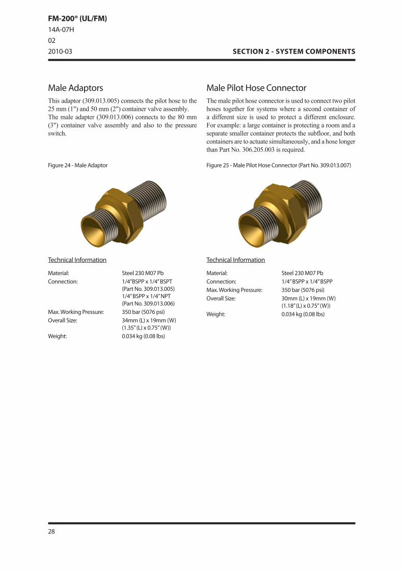
Figure24-MaleAdaptor
TechnicalInformation
Material: Steel230M07PbConnection: 1/4”BSPPx1/4”BSPT
(PartNo.309.013.00�)1/4”BSPPx1/4”NPT(PartNo.309.013.00�)
Max.WorkingPressure: 3�0bar(�07�psi)OverallSize: 34mm(L)x19mm(W)
(1.3�”(L)x0.7�”(W))Weight: 0.034kg(0.0�lbs)
TechnicalInformation
Material: Steel230M07PbConnection: 1/4”BSPPx1/4”BSPPMax.WorkingPressure: 3�0bar(�07�psi)OverallSize: 30mm(L)x19mm(W)
(1.1�”(L)x0.7�”(W))Weight: 0.034kg(0.0�lbs)
MalePilotHoseConnectorThe male pilot hose connector is used to connect two pilot hoses together for systems where a second container of a different size is used to protect a different enclosure��� For example: a large container is protecting a room and a separate smaller container protects the subfloor, and both containers are to actuate simultaneously, and a hose longer than Part No��� 306���205���003 is required���
Figure2�-MalePilotHoseConnector(PartNo.309.013.007)
MaleAdaptorsThis adaptor (309���013���005) connects the pilot hose to the 25 mm (1") and 50 mm (2") container valve assembly��� The male adapter (309���013���006) connects to the 80 mm (3") container valve assembly and also to the pressure switch���
2�
SECTION 2 - SYSTEM COMPONENTS
FM-200® (UL/FM)14A-07H022010-03

MaleTeeThis is used primarily in manifold systems for connecting pilot lines from one slave container to the next���
Figure27-MaleTee(PartNo.309.013.021)
TechnicalInformation
Material: BrassConnection: 1/4”BSPPx1/4”BSPPx1/4”NPTMax.WorkingPressure: 4�0bar(��27psi)OverallSize: 42mm(L)x29mm(W)
(1.��”(L)x1.14”(W))Weight: 0.07�kg(0.17lbs)
TechnicalInformation
Material: BrassConnection: 1/4”NPTx1/4”NPTOverallSize: 2�mm(L)x1�mm(W)
(1.10”(L)x0.71”(W))Weight: 0.042kg(0.09lbs)
Figure2�-StreetElbow(PartNo.309.013.00�)
StreetElbowThis elbow can be used to connect a pilot hose to an 80 mm (3”) valve��� The street elbow’s 1/4” NPT male thread screws into the valve body actuation port��� The 1/4” NPT thread of the male adaptor (Part No��� 309���013���006) screws into the street elbow��� The flexible pilot hose (Part No��� 306���205���003) would then screw onto the male adaptor���
29© 2010 Macron Safety Systems (UK) Limited
SECTION 2 - SYSTEM COMPONENTS
EQUIPMENT: FM-200® (UL/FM)PUBLICATION: 14A-07HISSUENo. 02DATE: 2010-03

PressureSwitchThe pressure switch is activated by pressure from the agent during discharge and can be used to signal to a control panel that the system has actually discharged��� The pressure switch latches on operation and has a reset button��� The pressure switch is supplied with a 1/4” BSPP x 1/4” NPT male adaptor (Part No��� 309���013���006)���
Figure29-PressureSwitch(PartNo.304.20�.007)Figure2�-MaleElbow(PartNo.309.013.009)
TechnicalInformation
Material: BrassConnection: 1/4”BSPPx1/4”NPTMax.WorkingPressure: 4�0bar(��27psi)OverallSize: 2�mm(L)x2�mm(W)
(1.10”(L)x1.00(W))Weight: 0.0�0kg(0.11lbs)
TechnicalInformation
Housing: Die-castAluminiumPressureConnection: NickelPlatedBrassSwitchPoint: 4barRising(��psi)Tolerance: ±0.34bar(±�psi)IPRating: IP��Connection: 1/4”NPTFemaleConduitThread: 1/2”NPTFemaleMax.WorkingPressure: 103.4bar(1�00psi)DCSwitchRating: 1A24vdcInstallationEnvironment: non-corrosive/indoorOverallSize: 1��mm(L)x101mm(W)
(�.�0”(L)x3.9�(W))Weight: 1.22kg(2.�9lbs)
MaleElbowThis elbow can be used on the last slave container when the pressure switch connection is taken from the manifold or piping networks���
30
SECTION 2 - SYSTEM COMPONENTS
FM-200® (UL/FM)14A-07H022010-03
HYGOOD
FM-200® Installation Guide/11100/02.08.05/Issue 3.3 25
SECTION 2 - SYSTEM COMPONENTS
Discharge Nozzle
FM-200® is distributed within the protected area by thedischarge nozzle which is sized to ensure the correctflow of agent for the risk��� Nozzles are available with sevenor eight ports to allow for 180o or 360o horizontal dis-charge patterns��� Ports are drilled in 0���1mm (0���004 in) in-crements to the specified system design��� BSP nozzlesare supplied as standard in Brass and Stainless Steelwith NPT as optional���
Technical Information
Material: Brass / Stainless Steel
Figure 21 - 7 & 8 Port Nozzle Brass Configuration
10mm (3/8") BSP Nozzle: Part No. 3381/215mm (1/2") BSP Nozzle: Part No. 3391/220mm (3/4") BSP Nozzle: Part No. 3401/225mm (1") BSP Nozzle: Part No. 3411/232mm (1 1/4") BSP Nozzle: Part No. 3421/240mm (1 1/2") BSP Nozzle: Part No. 3431/250mm (2") BSP Nozzle: Part No. 3441/2
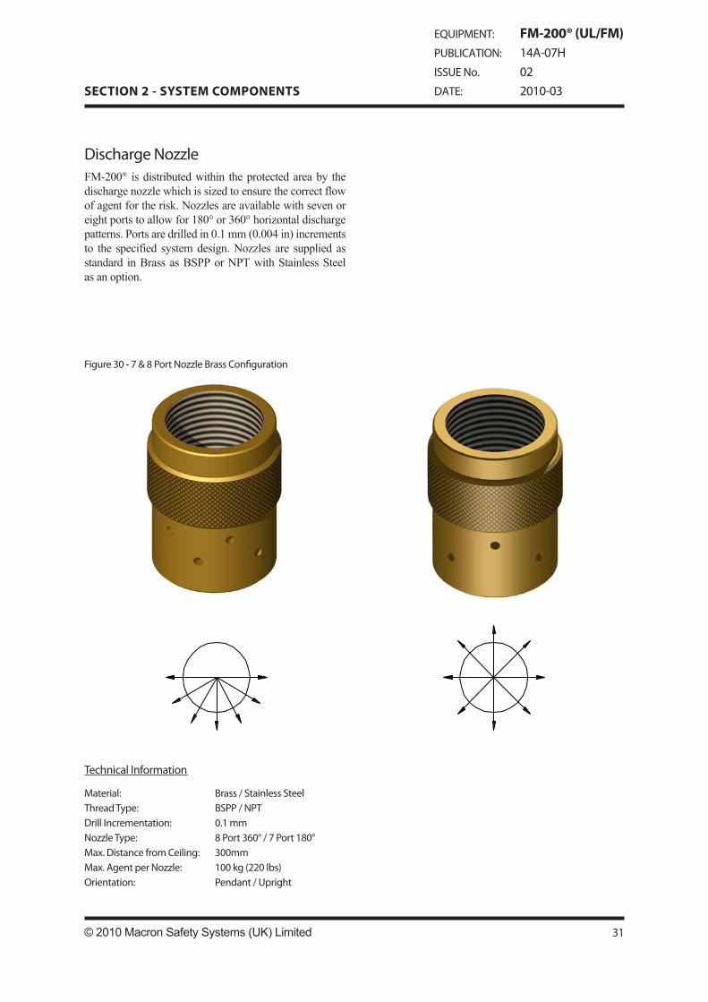
DischargeNozzleFM-200® is distributed within the protected area by the discharge nozzle which is sized to ensure the correct flow of agent for the risk��� Nozzles are available with seven or eight ports to allow for 180° or 360° horizontal discharge patterns��� Ports are drilled in 0���1 mm (0���004 in) increments to the specified system design��� Nozzles are supplied as standard in Brass as BSPP or NPT with Stainless Steel as an option���
TechnicalInformation
Material: Brass/StainlessSteelThreadType: BSPP/NPTDrillIncrementation: 0.1mmNozzleType: �Port3�0°/7Port1�0°Max.DistancefromCeiling: 300mmMax.AgentperNozzle: 100kg(220lbs)Orientation: Pendant/Upright
Figure30-7&�PortNozzleBrassConfiguration
31© 2010 Macron Safety Systems (UK) Limited
SECTION 2 - SYSTEM COMPONENTS
EQUIPMENT: FM-200® (UL/FM)PUBLICATION: 14A-07HISSUENo. 02DATE: 2010-03

Table9:DischargeNozzles
NozzleOverallSizes
NozzleSize Length Diameter10mm(3/�”) 33.�mm(1.32”) 2�mm(0.9�”)1�mm(1/2”) 41mm(1.�1”) 29mm(1.14”)20mm(3/4”) 47mm(1.��”) 34.�mm(1.3�”)2�mm(1”) �2mm(2.0�”) 41.3mm(1.�3”)32mm(1¼”) �2mm(2.44”) �0mm(1.97”)40mm(1½”) ��mm(2.��”) �0mm(2.3�”)�0mm(2”) �9mm(3.�0”) 7�mm(2.99”)
NozzleWeights
NozzleSize Brass StainlessSteel10mm(3/�”) 0.10kg(0.22lbs) 0.09kg(0.20lbs)1�mm(1/2”) 0.1�kg(0.33lbs) 0.14kg(0.31lbs)20mm(3/4”) 0.21kg(0.4�lbs) 0.20kg(0.44lbs)2�mm(1”) 0.27kg(0.�0lbs) 0.2�kg(0.��lbs)32mm(1¼”) 0.41kg(0.90lbs) 0.3�kg(0.�4lbs)40mm(1½”) 0.4�kg(1.01lbs) 0.43kg(0.9�lbs)�0mm(2”) 0.�3kg(1.�3lbs) 0.7�kg(1.72lbs)
32
SECTION 2 - SYSTEM COMPONENTS
FM-200® (UL/FM)14A-07H022010-03
Part Nozzle Nozzle Nozzle Thread Number Size Type Material Type
310.20�.201 10mm(3/�”) 7Port1�0° Brass BSPP
310.20�.202 10mm(3/�”) �Port3�0° Brass BSPP
310.20�.203 1�mm(1/2”) 7Port1�0° Brass BSPP
310.20�.204 1�mm(1/2”) �Port3�0° Brass BSPP
310.20�.20� 20mm(3/4”) 7Port1�0° Brass BSPP
310.20�.20� 20mm(3/4”) �Port3�0° Brass BSPP
310.20�.207 2�mm(1”) 7Port1�0° Brass BSPP
310.20�.20� 2�mm(1”) �Port3�0° Brass BSPP
310.20�.209 32mm(1¼”) 7Port1�0° Brass BSPP
310.20�.210 32mm(1¼”) �Port3�0° Brass BSPP
310.20�.211 40mm(1½”) 7Port1�0° Brass BSPP
310.20�.212 40mm(1½”) �Port3�0° Brass BSPP
310.20�.213 �0mm(2”) 7Port1�0° Brass BSPP
310.20�.214 �0mm(2”) �Port3�0° Brass BSPP
310.20�.21� 10mm(3/�”) 7Port1�0° Brass NPT
310.20�.21� 10mm(3/�”) �Port3�0° Brass NPT
310.20�.217 1�mm(1/2”) 7Port1�0° Brass NPT
310.20�.21� 1�mm(1/2”) �Port3�0° Brass NPT
310.20�.219 20mm(3/4”) 7Port1�0° Brass NPT
310.20�.220 20mm(3/4”) �Port3�0° Brass NPT
310.20�.221 2�mm(1”) 7Port1�0° Brass NPT
310.20�.222 2�mm(1”) �Port3�0° Brass NPT
310.20�.223 32mm(1¼”) 7Port1�0° Brass NPT
310.20�.224 32mm(1¼”) �Port3�0° Brass NPT
310.20�.22� 40mm(1½”) 7Port1�0° Brass NPT
310.20�.22� 40mm(1½”) �Port3�0° Brass NPT
310.20�.227 �0mm(2”) 7Port1�0° Brass NPT310.20�.22� �0mm(2”) �Port3�0° Brass NPT
Part Nozzle Nozzle Nozzle Thread Number Size Type Material Type
310.20�.301 10mm(3/�”) 7Port1�0° Stainless BSPP
310.20�.302 10mm(3/�”) �Port3�0° Stainless BSPP
310.20�.303 1�mm(1/2”) 7Port1�0° Stainless BSPP
310.20�.304 1�mm(1/2”) �Port3�0° Stainless BSPP
310.20�.30� 20mm(3/4”) 7Port1�0° Stainless BSPP
310.20�.30� 20mm(3/4”) �Port3�0° Stainless BSPP
310.20�.307 2�mm(1”) 7Port1�0° Stainless BSPP
310.20�.30� 2�mm(1”) �Port3�0° Stainless BSPP
310.20�.309 32mm(1¼”) 7Port1�0° Stainless BSPP
310.20�.310 32mm(1¼”) �Port3�0° Stainless BSPP
310.20�.311 40mm(1½”) 7Port1�0° Stainless BSPP
310.20�.312 40mm(1½”) �Port3�0° Stainless BSPP
310.20�.313 �0mm(2”) 7Port1�0° Stainless BSPP
310.20�.314 �0mm(2”) �Port3�0° Stainless BSPP
310.20�.31� 10mm(3/�”) 7Port1�0° Stainless NPT
310.20�.31� 10mm(3/�”) �Port3�0° Stainless NPT
310.20�.317 1�mm(1/2”) 7Port1�0° Stainless NPT
310.20�.31� 1�mm(1/2”) �Port3�0° Stainless NPT
310.20�.319 20mm(3/4”) 7Port1�0° Stainless NPT
310.20�.320 20mm(3/4”) �Port3�0° Stainless NPT
310.20�.321 2�mm(1”) 7Port1�0° Stainless NPT
310.20�.322 2�mm(1”) �Port3�0° Stainless NPT
310.20�.323 32mm(1¼”) 7Port1�0° Stainless NPT
310.20�.324 32mm(1¼”) �Port3�0° Stainless NPT
310.20�.32� 40mm(1½”) 7Port1�0° Stainless NPT
310.20�.32� 40mm(1½”) �Port3�0° Stainless NPT
310.20�.327 �0mm(2”) 7Port1�0° Stainless NPT310.20�.32� �0mm(2”) �Port3�0° Stainless NPT
CAUTION!This area is protected by a FM-200®fire extinguishing system.
When alarm sounds or upon gas dischargeevacuate hazard area immediately.
After discharge do NOT re-enter until thoroughly ventilated.
FM-200®
CAUTION!DO NOT enter unlessextinguishing systemis locked off.
When alarm soundsevacuate hazard area.
After FM-200® discharge do NOT re-enter until thoroughly ventilated.
FM-200®
CAUTION!Ensure all
personnel are evacuated
before releasing FM-200®
FM-200®
FM-200®
RELEASE
ManualControl Point
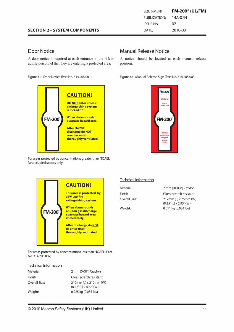
DoorNoticeA door notice is required at each entrance to the risk to advise personnel that they are entering a protected area���
Figure31-DoorNotice(PartNo.314.20�.001)
ManualReleaseNoticeA notice should be located at each manual release position���
Figure32-ManualReleaseSign(PartNo.314.20�.003)
ForareasprotectedbyconcentrationsgreaterthanNOAEL(unoccupiedspacesonly).
ForareasprotectedbyconcentrationslessthanNOAEL(PartNo.314.20�.002).
TechnicalInformationMaterial 2mm(0.0�”)Craylon
Finish Gloss,scratchresistant
OverallSize: 210mm(L)x210mm(W)(�.27”(L)x�.27”(W))
Weight: 0.02�kg(0.0��lbs)
TechnicalInformation
Material 2mm(0.0�in)Craylon
Finish Gloss,scratchresistant
OverallSize: 212mm(L)x7�mm(W)(�.3�”(L)x2.9�”(W))
Weight: 0.011kg(0.024lbs)
33© 2010 Macron Safety Systems (UK) Limited
SECTION 2 - SYSTEM COMPONENTS
EQUIPMENT: FM-200® (UL/FM)PUBLICATION: 14A-07HISSUENo. 02DATE: 2010-03
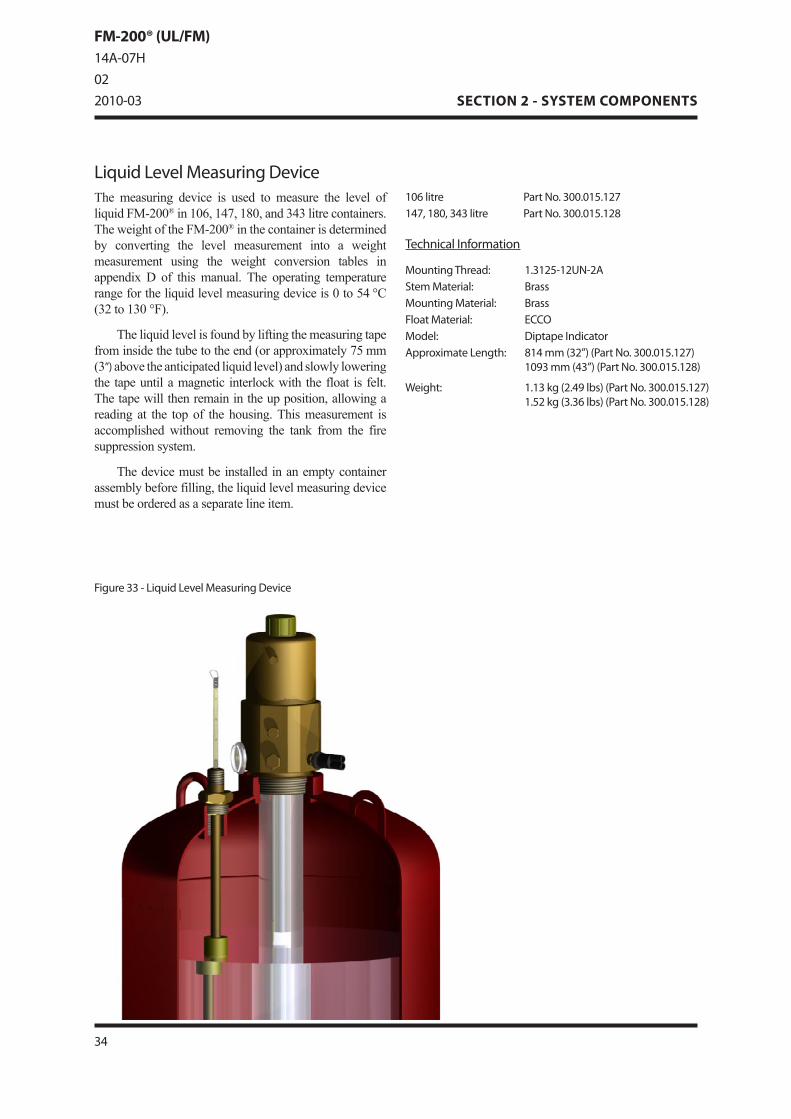
LiquidLevelMeasuringDeviceThe measuring device is used to measure the level of liquid FM-200® in 106, 147, 180, and 343 litre containers��� The weight of the FM-200® in the container is determined by converting the level measurement into a weight measurement using the weight conversion tables in appendix D of this manual��� The operating temperature range for the liquid level measuring device is 0 to 54 °C (32 to 130 °F)���
The liquid level is found by lifting the measuring tape from inside the tube to the end (or approximately 75 mm (3”) above the anticipated liquid level) and slowly lowering the tape until a magnetic interlock with the float is felt��� The tape will then remain in the up position, allowing a reading at the top of the housing��� This measurement is accomplished without removing the tank from the fire suppression system���
The device must be installed in an empty container assembly before filling, the liquid level measuring device must be ordered as a separate line item���
Figure33-LiquidLevelMeasuringDevice
TechnicalInformation
MountingThread: 1.312�-12UN-2AStemMaterial: BrassMountingMaterial: BrassFloatMaterial: ECCOModel: DiptapeIndicatorApproximateLength: �14mm(32”)(PartNo.300.01�.127)
1093mm(43”)(PartNo.300.01�.12�)
Weight: 1.13kg(2.49lbs)(PartNo.300.01�.127)1.�2kg(3.3�lbs)(PartNo.300.01�.12�)
10�litre PartNo.300.01�.127147,1�0,343litre PartNo.300.01�.12�
34
SECTION 2 - SYSTEM COMPONENTS
FM-200® (UL/FM)14A-07H022010-03

TypicalManifoldSystemFigure 34 indicates a typical two container system complete with electrical actuation, manual actuator, pressure switch, 2 x low pressure switch, flexible connections, distribution pipework and nozzles���
Figure34-TypicalManifoldSystem
3�© 2010 Macron Safety Systems (UK) Limited
SECTION 2 - SYSTEM COMPONENTS
EQUIPMENT: FM-200® (UL/FM)PUBLICATION: 14A-07HISSUENo. 02DATE: 2010-03