fluidized bed combustion research and development in ... · pdf filefluidized bed combustion...
TRANSCRIPT

FLUIDIZED BED COMBUSTION RESEARCH
AND DEVELOPMENT IN SWEDEN – A HISTORICAL SURVEY
by
Bo LECKNER
Review paperUDC: 662.62–912
BIBLID: 0354–9836, 7 (2003), 2, 3-16
A sur vey is made on re search and de vel op ment re lated to fluidised bedboil ers in Swe den dur ing the past two de cades, where sev eral Swed ishen ter prises took part: Gen er a tor, Götaverken, Stal Laval (ABB Car -bon), and Studsvik. Chalmers Uni ver sity of Tech nol ogy con trib uted inthe field of re search re lated to emis sions, heat trans fer and fluid dy -nam ics, and some re sults from this ac tiv ity are briefly sum ma rised.
Key words: combustion technologies, fluidized bed combustion,boilers, research and development
Background
The mo tives for com bus tion re search and de vel op ment dif fer from coun try tocoun try de pend ing on the en ergy sup ply and de mand sit u a tion and po lit i cal pref er ences. In or der to un der stand the Swed ish sit u a tion, it must be re al ized that the elec tric en ergyde mand is sat is fied by about equal parts of hy dro power and nu clear power. For this rea -son there are no re cent power sta tions based on com bus tion. On the other hand, a largepart of Swe den’s en ergy sup ply is di rected to space heat ing sup plied by dis trict heat ingsys tems. There fore, the large scale plants of in ter est in con nec tion with com bus tion inSwe den are not util ity boil ers but dis trict heat ing and in dus trial boil ers for heat or com -bined heat and power pro duc tion.
Af ter the Sec ond World War there was a rapid in crease in the use of oil, andsolid fu els were aban doned. The oil pe riod ended in the 1970s as a con se quence of theris ing oil prices, which stim u lated the con ver sion from oil to var i ous en ergy sources andto sav ing en ergy. Af ter the Swed ish ref er en dum in 1980, in which it was de cided to phaseout nu clear power, it be came clear that coal was pref er a ble as a pri mary source of en ergy for ex ist ing boil ers as well as for pos si ble fu ture elec tric util ity boil ers, which would beneeded to re place nu clear power. A com pre hen sive in ves ti ga tion •1• stated that coal wasen vi ron men tally ac cept able, and the use of coal could in crease. In the be gin ning of the1990s, un der the im pres sion of the threat en ing green house ef fect, coal again be came un -ac cept able and the use of biofuels was en cour aged by a suit able tax a tion •2•. Fig ure 1shows the price re la tions be tween var i ous fu els with and with out tax. The fig ure con tains
3

part of the ex pla na tion for the sub stan tial use of biofuels in Swe den that fol lowed –biofuels be came cheaper than other fu els be cause of tax a tion. The other parts of the ex -pla na tion were the avail abil ity of wood waste in the for ests and the suit able size and lo ca -tion of the dis trict heat ing plants.
So far there is lit tle nat u ral gas in Swe den, but a cer tain in ter est has been shownfrom neigh bour ing coun tries (Nor way, Rus sia (across Fin land), and Den mark) for an in -creased sup ply of nat u ral gas. In sum mary: there was an oil pe riod 1950-1975, a coal pe -riod 1975-1990, and a bio mass pe riod start ing from 1990. Will the next pe riod be a gaspe riod?
In the end of the oil pe riod the gov ern ment in Swe den, as well as in other coun -tries, de cided to ac tively sup port re search and de vel op ment to re duce the strong de -pend ence on oil con sump tion. In the programme area re lated to com bus tion inlarge-scale plants this ac tiv ity fo cussed on the uti li sa tion of solid fu els in dis trict heat ingand in dus trial boil ers. A con sid er able de vel op ment and re search ac tiv ity was ini ti ated.
Boilers
As will be seen, the prob lem area is even more lim ited than to dis trict heat ingand in dus trial boil ers in gen eral. It also de pends on the de gree of tech ni cal de vel op mentof pos si ble com bus tion de vices and the en vi ron men tal re quire ments. There are threeways to burn solid fu els: com bus tion of pul ver ised fu els in sus pen sion (flame), com bus -tion on grate (fixed or mov ing bed), and com bus tion in fluidised bed.
Compared to the other meth ods, fluidised bed com bus tion (FBC) was not at allde vel oped in the 1970s, but it was deemed to be a prom is ing tech nique hav ing prop er ties that suite the Swed ish re quire ments: in her ently low emis sion lev els and fuel flex i bil ity.
4
THERMAL SCIENCE: Vol. 7 (2003), No. 2, pp. 3-16
Figure 1. Electricity production costs for new cogeneration plants with andwithout taxes •2•

There fore it was nat u ral to fo cus at ten tion on FBC. The re search and de vel op ment ac -tiv ity re lated to FBC took place at Chalmers Uni ver sity of Tech nol ogy (CTH), StudsvikEn ergy AB, and in the boiler man u fac tur ing com pa nies Götaverken and Gen er a tor(Later they were united un der var i ous names. At pres ent the name is Kvaerner PulpingAB, in clud ing also the Finn ish com pany pre vi ously called Tampella). Stal Laval de vel -oped a boiler to fit their gas tur bine, a pres sur ised fluidised bed combustor (PFBC), andthe com pany ABB Car bon was formed for this pur pose. At the turn of the cen tury thisac tiv ity was sold to Alstom.
Early designs
An ap pli ca tion for eco nomic sup port to build an FBC boiler was sub mit ted byGen er a tor AB and CTH in 1977. Three years later a grant was given by the gov ern mentto build a dem on stra tion plant. This unit should also serve for heat ing of the uni ver sityand it could be used as a re search plant. The boiler, put into op er a tion in 1982, is seen infig. 2. This 16 MWt steam boiler has many in no va tive fea tures: the bot tom is sec tionedfor load con trol by bed “slump ing”, in-bed heat exchangers in the form of wings ex -tended from the mem brane-tube walls, a start-up com bus tion cham ber was lo cated be -low the bed, etc. A thor ough de scrip tion isfound in ref. •3•. The fluidisation ve loc itywas ini tially 2.5 m/s at full load. Var i ous fu -els could be used, but coal was the de signfuel. It soon be came ev i dent that the in-bed tubes were se verely eroded by the bed. Allwing-tubes in the bed, but not those of thesuperheater needed for steam pro duc tion,had to be re moved and the boiler wasde-rated to 10 MW. Metal coat ings to ex -tend the life time were then ap plied to thesuperheater, as well as to the re main ingver ti cal tube-walls. An other les son learnedwas that recirculation of ashes was nec es -sary dur ing com bus tion of coal to ob tain anac cept able com bus tion ef fi ciency. Amulticlone fil ter was avail able, from wheresome recircula- tion of ashes could havebeen achieved, but ero sion and plug ging af -fected its per for mance. How ever, the ini -tial problems were over come and the boiler was op er ated with out some heat trans fersur face at re duced load (lower fluidisationve loc ity) for sev eral years un til 1990, whena new fluidised bed boiler was put into op -
5
Leckner, B., Fluidized Bed Combustion Research and Development in Sweden ...
Figure 2. The 16 MW FBC boiler at ChalmersUniversity of Technology •3•

er a tion, this time a cir cu lat ing FBC (CFBC) de signedfor re search, but also, as pre vi ously, for heat ing of theuni ver sity. A pic ture of the 12(8) MWt CFB boiler ispre sented in fig. 3.
At about the same time Studsvik de vel oped an al -ter na tive CFBC, fig. 4, which con tained many uniquede sign el e ments: a U-beam par ti cle sep a ra tor to avoid the ex pen sive cy clone, an L-valve reinjection for con -trolled par ti cle cir cu la tion to ad just the par ti cle in ven -tory in the bed, and a fur nace with a par tic u lar shape•5•. The de sign at tracted the at ten tion of Bab cock &Wilcox to the ex tent that they bought a licence. Morethan ten boil ers were pro duced ac cord ing to this con -cept, but Bab cock & Wilcox de vel oped the de sign fur -ther and to day mostly the U-beam sep a ra tor, con -verted to an in ter nal sep a ra tion de vice in side the fur -nace, re mains from the orig i nal de sign •6•. The idea to re place the con ven tional cy clone can now be seen insev eral other de signs.
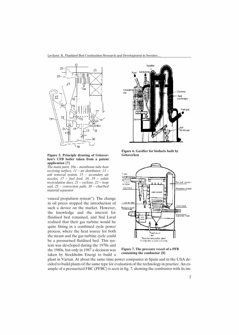
To make the pic ture com plete it should be men -tioned that Götaverken also started de vel op ment ofCFBC in the be gin ning of the 1980s. Fig ure 5, taken
from a pat ent ap pli ca tion, gives anidea of their de sign. Götaverkenwas suc cess ful in rap idly in tro duc ing their prod uct on the mar ket, en -coun tered a great deal of dif fi cul ties of op er a tion, but solved the prob -lems and had a ma ture de sign at theend of the de cade. This com panyalso de vel oped a CFB gasifier forbio mass to be used in the pulp andpa per in dus try to re place oil, fig. 6.One com mer cial plant was suc cess -fully put into op er a tion (Värö bruk)be fore the oil prices again fell andmade this type of gasifier less in ter -est ing. This plant is still (2003) inop er a tion, how ever.
Al ready at the end of the 1960sand in the be gin ning of the 1970sStal Laval was de vel op ing a flu-idised bed superheater to be in -stalled in ship ma chin ery (“very ad -
6
THERMAL SCIENCE: Vol. 7 (2003), No. 2, pp. 3-16
Figure 3. The 12 MW (8 MWmaximum continuous rating)CFB boiler at ChalmersUniversity of Technology •4•
Figure 4. Layout of a 35 MW CFB boiler based on theStudsvik prototype •5•1 – fuel feed, 2 – secondary air supply, 3 – combustionchamber, 4 – U-beam separator, 5 – cyclone for finalparticle separation, 6 – convection path, 7 – settlingchamber for ash separation, 8, 9 – ash recirculationarrangement
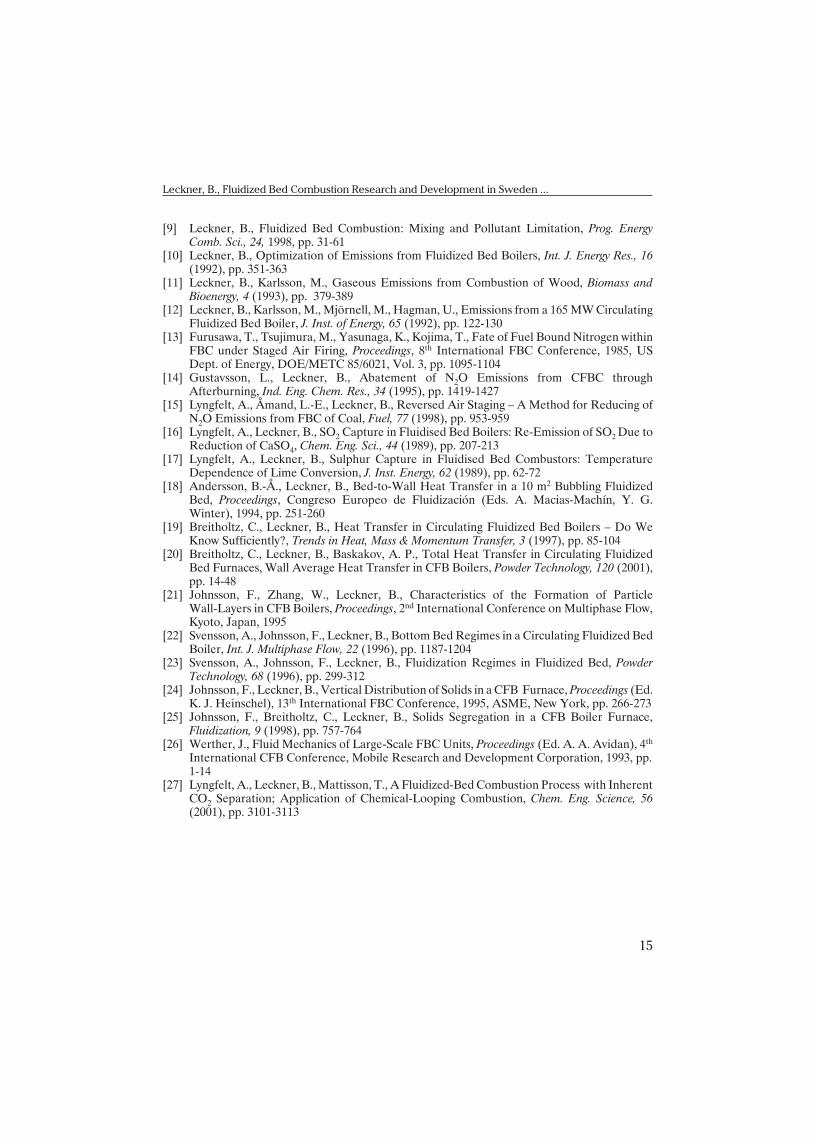
vanced pro pul sion sys tem”). The changein oil prices stopped the in tro duc tion ofsuch a de vice on the mar ket. How ever,the knowl edge and the in ter est forfluidised bed re mained, and Stal Lavalreal ised that their gas tur bine would bequite fit ting in a com bined cy cle powerpro cess, where the heat source for boththe steam and the gas tur bine cy cle couldbe a pres sur ised fluidised bed. This sys -tem was de vel oped dur ing the 1970s andthe 1980s, but only in 1987 a de ci sion wastaken by Stock holm Energi to build aplant in Värtan. At about the same time power com pa nies in Spain and in the USA de -cided to build plants of the same type for eval u a tion of the tech nol ogy in prac tice. An ex -am ple of a pres sur ised FBC (PFBC) is seen in fig. 7, show ing the combustor with its im -
7
Leckner, B., Fluidized Bed Combustion Research and Development in Sweden ...
Figure 6. Gasifier for biofuels built byGötaverken
Figure 7. The pressure vessel of a PFBcontaining the combustor •8•
Figure 5. Principle drawing of Götaver-ken’s CFB boiler taken from a patentapplication •7•The main parts: 10a – membrane tube heatreceiving surface, 11 – air distributor, 13 –ash removal system, 15 – secondary airnozzles, 17 – fuel feed, 18, 19 – solidsrecirculation duct, 21 – cyclone, 22 – loopseal, 25 – convection path, 30 – char/bedmaterial separator

mersed boiler tubes, cy clones and other ar range ments in side the pres sure ves sel. Theyear 2003 the Värtan plant is still in op er a tion, the Span ish plant is op er ated oc ca sion ally as part of the power sys tem, and the Amer i can plant is dis man tled.
In ves ti ga tions
What has been learned about the com bus tion be hav iour of FBC? Fo cussing at -ten tion on the work at CTH there are three ma jor sub ject ar eas: emis sions, heat trans fer, and fluid dy nam ics. A gen eral re view of this prob lem area, in clud ing the work at CTH,has been pub lished •9•. Here a few com ments will be made.
Emis sions
The aim of the in ves ti ga tions on emis sions was to show the emis sion prop er tiesof an FBC, and if pos si ble, to ex plain the mech a nisms be hind the emis sions. The early re -sults have been sum ma rised in •10•. The fol low ing ob ser va tions were made:· The emis sions are in flu enced by a great num ber of boiler op er a tion pa ram e ters. This
is what makes FBC in ter est ing; there are sev eral prom is ing ways to go for op ti -mi sa tion.
· Bed tem per a ture and ex cess air are the two most im por tant pa ram e ters to in flu encethe NO emis sion dur ing com bus tion of coal, but they are not ef fi cient dur ingcom bus tion of biofuels •11•. The ex pla na tion for the in sen si tiv ity of an FBC burn ingbiofuels is most likely found in the small char con tent of the bed for such fuel, tentimes less than for coal. Char is a prin ci pal re duc ing agent for NO and its con tent isaf fected by fuel type, tem per a ture and ox y gen con cen tra tion.
· CFBC tends to pro mote the con ver sion of fuel ni tro gen to NO for high vol a tile fu els,whereas sta tion ary fluidised bed com bus tion (SFBC) shows an op po site trend. Theex pla na tion of this be hav iour re mains to be found. This is a task for on go ing work.
· The con ver sion of fuel ni tro gen to NO emit ted is al most in de pend ent of the fuelni tro gen con tent be cause de struc tion is re lated to the com bus tion sit u a tion, andde struc tion dom i nates over fuel de pend ent for ma tion. An ex treme ex am ple is thatwood, whose ni tro gen con tent is small, yields an emis sion of the same mag ni tude ascoal, whose ni tro gen con tent is much greater (CFB con di tions).
· It was dis cov ered that N2O is emit ted from FBC but not sig nif i cantly from othercom bus tion de vices. The ex pla na tion is that the tem per a ture range of op er a tion ofFBC is fa vour able for for ma tion of N2O at the same time as re duc tion is slow.
· The emis sion of N2O is re lated to air ex cess just like that of NO but the in flu ence oftem per a ture is re versed, fig. 8.
· The bed ma te rial has a cat a lytic in flu ence on cer tain re ac tions in the bed. For ex am -ple: the NO emis sion rises when lime stone is added for sul phur cap ture. Par tic u larly,po rous CaO is ac tive in con ver sion of am mo nia •13•, but most of the CaO sur face isde ac ti vated by CaSO4 formed by sul phur cap ture. CaSO4 has an in sig nif i cant ef fect
8
THERMAL SCIENCE: Vol. 7 (2003), No. 2, pp. 3-16

on the re ac tions form ing NO. So, dur ing an ex cess ad di tion of lime stone the NOemis sion in creases dra mat i cally be cause of the larger avail abil ity of unreacted CaO.CaO also con trib utes some what to the re duc tion of N2O, see fig. 8.
· A com pre hen sive work to un der stand the fac tors in flu enc ing the N2O emis sionre sulted in pro pos als of sev eral re duc tion meth ods •14, 15•.
· The well-known tem per a ture de pend ence of sul phur cap ture was stud ied. (There isan op ti mum of sul phur cap ture at 850 °C and this is one of the rea sons why FBC ismost fre quently op er ated at this tem per a ture). The rea son for the tem per a turede pend ence was ex plained to be lo cal and tem po rary re duc ing con di tions in the bed,de spite to tal ex cess air •16, 17•.
· As a con se quence of this in sight and know ing the ther mo dy nam ics of the sys tem:SO2, O2 ,CaO, CaS, and CaSO4 it was pos si ble to ex plain the sul phur cap turebe hav iour of dif fer ent types of FBC op er at ing with dif fer ent types of fuel.
Heat transfer
There is an over whelm ing num ber of cor re la tions pub lished on heat trans fer tosur faces in bub bling fluidised beds. The prob lem has been ap proached in two ways: (1)by mech a nis tic mod els, such as par ti cle re place ment mod els, or (2) by cor re la tions, the
9
Leckner, B., Fluidized Bed Combustion Research and Development in Sweden ...
Figure 8. Influence of bed temperature on the emission of NO and N2O during combustion of coalin a 165 MW boiler in Örebro •12•

sim plest and most use ful one be ing Zabrodski’s for mula. How ever, no heat trans fer re la -tion ship helps if the fluid dy namic sit u a tion at the heat trans fer sur face is not un der -stood. The back ground to this re mark is that al most all work on heat trans fer in FBC isbased on ex pe ri ences from lab o ra tory equip ment and the cor re spond ing re sults can notreadily be trans ferred to the sit u a tion in a combustor bed. There is a very lim ited ex pe ri -ence re ported from large-scale combustors. A strik ing ex am ple from the 16 MW boilerat Chalmers is shown in fig. 9. The heat trans fer to the walls sur round ing the bed is high -est at the sur face of the bed and de clines up wards, not sur pris ing, since the par ti cle den -sity de clines up wards. It is more sur pris ing that it also de clines down wards from the sur -face, ob vi ously de pend ent on the move ments of the bed, the same move ments that cause ero sion on the heat trans fer sur face, as il lus trated by the ac com pa ny ing di a gram of fig. 9.It is not pos si ble to es ti mate this be hav iour by means of avail able cor re la tions.
How ever, the sta tion ary FBC was aban doned for coal com bus tion, and in steadsub se quent at ten tion was di rected to wards CFB, where heat trans fer to the ver ti cal wallsur faces would avoid ero sion. The re sults ob tained at Chalmers were com pared with thefew other data pub lished from boil ers and hot re search units, Fig. 10, and the ques tionwas asked: “do we know suf fi ciently?”•19•. In te grating along the height of the com bus -tion cham ber these data can be fur ther re duced •20•:
10
THERMAL SCIENCE: Vol. 7 (2003), No. 2, pp. 3-16
Fig ure 9. Ma te rial loss due to ero sion (left di a gram) and heat trans ferco ef fi cient (right di a gram) to the wall of a bub bling bed [18]

a= 110r0.21 (1)
where a •W/m2, de gree• is the av er age heat trans fer co ef fi cient over the en tire wallcon sist ing of heat trans fer sur face, cal cu lated as pro jected sur face. The sus pen sionden sity r •kg/m3• is an av er age over the cor re spond ing fur nace vol ume.
All in for ma tion avail able is con densed into eq. (1) which is valid for heights be -tween 2 and 20 m. The ob vi ous sim pli fi ca tions are con tained within the lim its of ac cu racy of the data. If this in for ma tion is suf fi cient for the man u fac tur ing in dus try, then the an -swer to the ques tion is yes. If eq. (1) is not suf fi cient, then work should be done to fur ther ex plain the mech a nisms of CFBC heat trans fer and, be cause of the strong con nec tion, offluid dy nam ics.
Fluid dynamics
As long as fluidisation stud ies are re stricted to low fluidisation ve loc i ties theycan con ve niently be car ried out in small lab o ra tory equip ment. When the ve loc ity in -creases, the bub ble size in creases and even tu ally the bub bles be come re stricted by theequip ment. This di lemma is sig nif i cant in CFB, op er ated at high ve loc i ties, for which
11
Leckner, B., Fluidized Bed Combustion Research and Development in Sweden ...
Fig ure 10. Heat trans fer co ef fi cients mea sured un der hotcon di tions vs. cross-sec tion av er age sus pen sion den sity [19]

large cross-sec tions are quite dif fi cult to han dle in the lab o ra tory. As a re sult, most re -search work re lated to CFB is car ried out in tall but nar row test tubes. Ex am ples fromdif fer ent equip ment are shown in fig. 11.
These test tubes dif fer from combustors in the sense that the lat ter have largecross-sec tions. For this rea son fluidisation is seen from dif fer ent an gles in the two typesof equip ment. The re search at Chalmers has been for tu nate to have ac cess to large-scaleequip ment, thus avoid ing the wall ef fects. Three re gions of the riser have been stud ied:the bot tom bed, the splash zone, and the trans port zone.
De spite the high gas ve loc i ties of the CFB a dense bot tom bed is main tained, andits be hav iour was found to be sim i lar to a bub bling bed •22, 23•. The ex pla na tion is that allbed par ti cles do not ex pe ri ence the high ve loc i ties, be cause of by-pass of gas through thebub bles. Above the bot tom bed there is a splash zone, formed by par ti cles thrown up by themove ments of the bot tom bed. In this zone there is a high re flux of par ti cles. The re sult ingpro file of par ti cle con cen tra tion ver sus height is ex po nen tial and ex tends a me ter or two
12
THERMAL SCIENCE: Vol. 7 (2003), No. 2, pp. 3-16
Fig ure 11. Ver ti cal mea sure ment po si tion and to tal riser height for boil ers (cases above thedashed line) and lab o ra tory ris ers, both re lated to the riser di am e ter [21]

from the bed. The ex po nen tial de cay ischar ac ter ised by a “de cay co ef fi cient”, sim i -lar to what has been ob served pre vi ously inbub bling beds •24•. This is not sur pris ing,con sid er ing the bub bling char ac ter of theCFB bot tom bed. Above the splash zonepar ti cles are car ried away with the gas, butthere is a con tin u ous sep a ra tion of par ti cles into the wall lay ers of de scend ing par ti cles.Also in this re gion the ex po nen tial de cay ofcross-sec tion av er age par ti cle den sity canbe char ac ter ised by a de cay co ef fi cient. The cross-sec tion av er age den sity pro file canthus be de scribed by two ex po nen tials •24•.The cor re spond ing par ti cle fluxes can beeval u ated and in this way, based on em pir i -cal data, the par ti cle flows can be cal cu -lated. Fig ure 12 il lus trates the re sult of anes ti ma tion of the (ex ter nally) cir cu lat ingflux Gs •kg/m2s• and cor re spond ing fuelflows: fuel feed flow Fx •kg/m2•, in ter nal cir -cu la tion flow 9Fx and the ex ter nal cir cu la -tion flow 3Fx. It is in ter est ing to see that the in ter nal recirculation of fuel par ti cles is 3 timesgreater than the ex ter nal one and 9 times greater than the fuel flow in this ex am ple.
The nar row ris ers and the wide combustors are sim i lar in the re spect that in both casesthere is an up ward par ti cle flow in the core of the riser and a down ward flow of par ti cles atthe wall •26•. How ever, mea sured hor i zon tal flux pro files dif fer in shape: they are flat inboil ers and par a bolic in nar row ris ers. The ex pla na tion [24] is most likely that the low as -pect-ra tio boil ers are in a de vel op ing flow re gime, in anal ogy with sin gle-phase duct flow,whereas the nar row ris ers have al ready a de vel oped flow at the level where mea sure mentsare usu ally made (fig. 11).
In con clu sion, a de scrip tion of the ba sic fluid dy namic fea tures of a combustorhas been achieved. There are qual i ta tive sim i lar i ties with the com monly pub lished datafrom nar row ris ers, but there are also fun da men tal dif fer ences.
Trends
In the field of elec tric ity pro duc tion from large util ity plants there is a trend inEu rope and per haps else where to plan for use of nat u ral gas in large, highly ef fi cientcom bined cy cle power plants, built on the ba sis of avail able tech niques. In the sec ondplace there is a com pe ti tion be tween (highly ef fi cient) pul ver ised coal, sin gle cy cle,plants and com bined gasi fi ca tion/com bus tion gas/steam tur bine cy cles, where fluidised
13
Leckner, B., Fluidized Bed Combustion Research and Development in Sweden ...
Fig ure 12. Ex am ple of sol ids (fuel) flows in aCFB fur nace [25]

beds are suit able both for the gasifier and for the combustor (in the case of a com bi na -tion of both). The fuel would be coal.
On the small and in ter me di ate scale (but still large in the sense of this pa per)dis trict heat ing and in dus trial plants the sit u a tion is more di verse: in most cases “nor -mal” fu els will be used, but there is a strong ten dency to wards the uti li sa tion of “new” fu -els, such as wastes and biofuels, as pri mary fuel or in com bi na tion with a con ven tionalpri mary fuel: co-com bus tion. In the lat ter field of ap pli ca tion FBC is a strong can di date,be cause of its fuel flex i bil ity and if se vere en vi ron men tal re stric tions are im posed.
Tasks for re search are dif fi cult to gen er al ise, but if combustors are sorted upinto known tech nique, new tech nique, and pro posed tech nique, quite ob vi ously the ap -proaches are dif fer ent.
In the case of known tech nique (flame com bus tion, grate com bus tion) there is a need for pre dic tive meth ods in or der to achieve a better de sign of com bus tion cham berswith re spect to re li abil ity, ef fi ciency and emis sion per for mance.
In the case of new tech nique (FBC), in ad di tion to the above, there is a need tobetter un der stand the pro cesses in the com bus tion cham ber. Par tic u larly the time-de -pend ent char ac ter (fluc tu a tions) of the fluidised me dium should be in ves ti gated in or der to treat chem i cal re ac tions, re lated to com bus tion and pol lut ants, not only us ing time-av -er age data but with ac tual con cen tra tions. In this field the in creased per for mance ofcomputors cre ates new pos si bil i ties to de scribe the be hav iour of the two-phase me dium– a key to in ter pret ing ob ser va tions.
In the case of pro posed new tech niques (e. g. meth ods to re duce CO2 emis sions) a ba sic eval u a tion of var i ous pro pos als (re lated to com bus tion) is a prin ci pal task. Alsohere fluidised bed may play an im por tant role •27•.
Ref er ences
•1• ***, Health and Environmental Effects of Coal (in Swedish), Statens Vattenfallsverk(“Vattenfall”), Oc to ber 1981
•2• ***, Reorganisation of the Energy System (in Swedish), SOU 1995:139, 1995•3• Svens son, G., Leckner, B., The FLuidized Bed Boiler at Chalmers Uni ver sity of Tech nol ogy,
Proceedings, 7th International FBC Conference, US Dept. of En ergy, DOE/METC/983-48,1983, pp. 625-636
•4• Leckner, B., Golriz, M. R., Zhang, W., Andersson, B.-Å., Bound ary Lay ers – FirstMea sure ments in the 12 MW CFB Re search Plant at Chalmers Uni ver sity, Proceedings (Ed.E. J. An thony), 11th International FBC Conference, ASME, New York, 1991, pp. 771-776
•5• Strömberg, L., Fast FBC of Coal, Proceedings, 7th International FBC Conference, 1983, USDept. of En ergy, DOE/METC/983-48, pp. 1152-1163
•6• Belin, F., Maryamchik, M., Fuller, T. A., Perna. M. A., CFB Combustor with In ter nal Sol idsCir cu la tion – Pi lot Test ing and De sign Ap pli ca tions, Proceedings (Ed. K. J. Heinschel), 13th
International FBC Conference, ASME, New York, 1995, pp. 201-209•7• Kullendorff, A., Jansson, B., Olofsson, J., Process and Device for Control of the Heat
Transfer Coefficient of a CFB Boiler (in Swedish), Pat ent ap pli ca tion 850430 10202 282,1985
•8• Mudd, M. J., Sta tus of AEP´s Tidd PFBC Dem on stra tion Plant, Proceedings (Ed. A. M.Manaker), 10th International FBC Conference, 1989, ASME, New York, pp. 203-209
14
THERMAL SCIENCE: Vol. 7 (2003), No. 2, pp. 3-16
•9• Leckner, B., Fluidized Bed Com bus tion: Mixing and Pol lut ant Lim i ta tion, Prog. En ergyComb. Sci., 24, 1998, pp. 31-61
•10• Leckner, B., Op ti mi za tion of Emis sions from Fluidized Bed Boil ers, Int. J. En ergy Res., 16(1992), pp. 351-363
•11• Leckner, B., Karlsson, M., Gas eous Emis sions from Com bus tion of Wood, Bio mass andBioenergy, 4 (1993), pp. 379-389
•12• Leckner, B., Karlsson, M., Mjörnell, M., Hagman, U., Emis sions from a 165 MW Cir cu lat ingFluidized Bed Boiler, J. Inst. of En ergy, 65 (1992), pp. 122-130
•13• Furusawa, T., Tsujimura, M., Yasunaga, K., Kojima, T., Fate of Fuel Bound Ni tro gen withinFBC un der Staged Air Fir ing, Proceedings, 8th International FBC Conference, 1985, USDept. of En ergy, DOE/METC 85/6021, Vol. 3, pp. 1095-1104
•14• Gustavsson, L., Leckner, B., Abate ment of N2O Emis sions from CFBC throughAfter burning, Ind. Eng. Chem. Res., 34 (1995), pp. 1419-1427
•15• Lyngfelt, A., Åmand, L.-E., Leckner, B., Re versed Air Stag ing – A Method for Re duc ing ofN2O Emis sions from FBC of Coal, Fuel, 77 (1998), pp. 953-959
•16• Lyngfelt, A., Leckner, B., SO2 Cap ture in Fluidised Bed Boil ers: Re-Emis sion of SO2 Due toRe duc tion of CaSO4, Chem. Eng. Sci., 44 (1989), pp. 207-213
•17• Lyngfelt, A., Leckner, B., Sul phur Cap ture in Fluidised Bed Combustors: Tem per a tureDe pend ence of Lime Con ver sion, J. Inst. En ergy, 62 (1989), pp. 62-72
•18• Andersson, B.-Å., Leckner, B., Bed-to-Wall Heat Trans fer in a 10 m2 Bub bling FluidizedBed, Proceedings, Congreso Europeo de Fluidización (Eds. A. Macias-Machín, Y. G.Win ter), 1994, pp. 251-260
•19• Breitholtz, C., Leckner, B., Heat Trans fer in Cir cu lat ing Fluidized Bed Boil ers – Do WeKnow Suf fi ciently?, Trends in Heat, Mass & Mo men tum Trans fer, 3 (1997), pp. 85-104
•20• Breitholtz, C., Leckner, B., Baskakov, A. P., To tal Heat Trans fer in Cir cu lat ing FluidizedBed Fur naces, Wall Av er age Heat Trans fer in CFB Boil ers, Pow der Tech nol ogy, 120 (2001),pp. 14-48
•21• Johnsson, F., Zhang, W., Leckner, B., Char ac ter is tics of the For ma tion of Par ti cleWall-Lay ers in CFB Boil ers, Proceedings, 2nd International Conference on Multiphase Flow,Kyoto, Japan, 1995
•22• Svens son, A., Johnsson, F., Leckner, B., Bot tom Bed Re gimes in a Cir cu lat ing Fluidized BedBoiler, Int. J. Multiphase Flow, 22 (1996), pp. 1187-1204
•23• Svens son, A., Johnsson, F., Leckner, B., Fluidization Re gimes in Fluidized Bed, Pow derTech nol ogy, 68 (1996), pp. 299-312
•24• Johnsson, F., Leckner, B., Ver ti cal Dis tri bu tion of Sol ids in a CFB Fur nace, Proceedings (Ed. K. J. Heinschel), 13th International FBC Conference, 1995, ASME, New York, pp. 266-273
•25• Johnsson, F., Breitholtz, C., Leckner, B., Solids Seg re ga tion in a CFB Boiler Fur nace,Fluidization, 9 (1998), pp. 757-764
•26• Werther, J., Fluid Me chan ics of Large-Scale FBC Units, Proceedings (Ed. A. A. Avidan), 4th
International CFB Conference, Mo bile Re search and De vel op ment Cor po ra tion, 1993, pp. 1-14
•27• Lyngfelt, A., Leckner, B., Mattisson, T., A Fluidized-Bed Com bus tion Pro cess with In her ent CO2 Sep a ra tion; Ap pli ca tion of Chem i cal-Loop ing Com bus tion, Chem. Eng. Sci ence, 56(2001), pp. 3101-3113
15
Leckner, B., Fluidized Bed Combustion Research and Development in Sweden ...

Au thor’s ad dress:
B. LecknerChalmers Uni ver sity of Tehnology41296 Göteborg, Swe denE-mail: ble@en tek.chalmers.se
Paper submited: August 28, 2003Paper revised: September 3, 2003Paper accepted: September 7, 2003
16
THERMAL SCIENCE: Vol. 7 (2003), No. 2, pp. 3-16