fluid flow and stresses on microcarriers in spinner flask bioreactors · · 2012-11-0710-12...
TRANSCRIPT

Ninth International Conference on CFD in the Minerals and Process Industries
CSIRO, Melbourne, Australia
10-12 December 2012
Copyright © 2012 CSIRO Australia 1
FLUID FLOW AND STRESSES ON MICROCARRIERS IN SPINNER FLASK BIOREACTORS
Petar LIOVIC1*, Ilija D. ŠUTALO2, Robert STEWART2, Veronica GLATTAUER3 and Laurence MEAGHER3
1 CSIRO Mathematics, Informatics and Statistics, Highett, Victoria 3190, AUSTRALIA 2 CSIRO Materials Science and Engineering, Highett, Victoria 3190, AUSTRALIA 3 CSIRO Materials Science and Engineering, Clayton, Victoria 3169, AUSTRALIA
*Corresponding author, E-mail address: [email protected]
ABSTRACT
The paper presents a validated CFD model for the flow in
a bench-scale spinner flask that features a centrally-located
magnet-driven impeller. Model development found that
use of the immersed solid mesh method resulted in better
correspondence with observations and µPIV
measurements than the more established sliding mesh
method in ANSYS-CFX. Analysis of spatial distributions
suggested stresses and turbulence in a bench-scale stirred-
flask bioreactor featuring vertical outer-wall baffles were
of a magnitude which could result in inhibited growth due
to cell damage if the angular velocity was high enough,
even when the magnitude of the Reynolds number
indicated that the flow was barely turbulent.
NOMENCLATURE
N annular velocity
D stirrer diameter
lk Kolmogorov length scale
S shear strain rate
τ shear stress
ρ density
µ molecular viscosity
µT eddy viscosity
ε turbulence dissipation
INTRODUCTION
The scientific and engineering considerations associated
with realizing rapid human stem cell expansion on an
industrial-scale in high throughput bioreactors are varied
and significant. Unlike animal cells used for therapeutic
protein production, human adult stem cells (hSC) are more
sensitive to culture conditions than animal cell lines
(Allegrucci and Young, 2007). While high level expansion
in culture of hSCs is sought in high-throughput
bioreactors, it is preconditioned on minimizing variations
in lineage commitment and keeping genetic and epigenetic
instabilities under control. In order to achieve this in
upscaled bioreactor systems the process environment in
which hSC expansion occurs needs to be fully understood
(Hewitt et al., 2011).
While bench-scale technology development has generated
a multitude of bioreactor concepts for cultivating hSCs,
the complications associated with process scale-up
preclude many of these as infeasible for scale-up.
Bioreactor designs that currently stand out as being
scalable are suspension bioreactors featuring microcarrier
particles, which provide ample surface area for stem cell
attachment and expansion within feasibly compact
bioreactor volumes (Nienow, 2006). Utilization of the full
surface area of the microcarriers within a bioreactor, and
homogenization of the environment for stem cell
expansion on the microcarrier, requires the particles to be
suspended. The current preference for sustaining
suspension in culture within bioreactors is mechanical
agitation through stirring.
Agitation in bioreactors in the form of stirring induces
flow stresses which are capable of inducing damage to
stem cells and indeed to microcarriers (Croughan et al.,
1987; Hewitt et al., 2011). Damage-level stresses affecting
stem cell expansion are not the only concern in stirred-
tank bioreactor operation for hSCs. Low shear stress levels
have been noted by Cormier et al. (2006) to raise the
possibility of excessive agglomeration. In addition, shear
in bioreactor culture augmenting stem cell signalling has
been shown to have an effect on human mesenchymal
stem cell (hMSC) differentiation due to mechanisms such
as mitogen activated protein kinase (MAPK) signalling,
mechanotransduction, and writ signalling (Yeatts et al.,
2012). While it is a concern, Shafa et al. (2011) note
successful use of suspension bioreactors to support large-
scale stem cell expansion (in their case embryonic stem
cells) in a number of groups while retaining phenotype.
The distinction between shear influenced stem cell
differentiation and shear induced cell damage is important,
because of the flow characteristics associated with them.
The stress effect in stirred-flask stem cell bioreactors and
for more generic tissue engineering bioreactors tends to
report shear stress levels and exposure durations to
achieve a specific stem cell differentiation or stem cell
expression outcome that are either single values (e.g.
Glossop and Cartmell, 2009; Shafa et al., 2011; Yeatts et
al., 2012), a relatively narrow-band (e.g. Zhang et al.,
2011; Zhang et al., 2012), or maximum values (Cormier et
al., 2006). Cormier et al. (2006) provide justification for
suspension bioreactors featuring a narrow band of shear
stress levels by noting a limited range for cell
proliferation, based on competing considerations of shear-
induced damage and agglomeration. Turbulent flow in
stirred-flask bioreactors (Croughan et al., 1987; Hewitt et
al., 2011), however, represents a scenario that is not
characterized by a narrow band of shear stress levels. The
key phenomenology of turbulence - outscatter idealized as

Copyright © 2012 CSIRO Australia 2
the self-similar breakdown of large eddies into small ones
– is broad-band behaviour, as noted in the nature of the
turbulent energy cascade. The cascading of characteristic
shear stress magnitudes associated with a decreasing
turbulent eddy length scale means that shear stresses seen
by individual stem cells may be large and well beyond any
narrow band associated with the mean flow. Indeed, the
turbulent (Kolmogorov) microscale is postulated to be the
key criterion for determining whether cell damage will
occur (Croughan et al., 1987; Hewitt et al., 2011).
Turbulent fluctuations at the Kolmogorov scale also affect
cell attachment onto microcarriers. The effect of broad-
band stresses associated with turbulence on the ability of
stirred-flask bioreactor operation to preserve pluripotency
in stem cells and minimize lineage commitments is poorly
understood. While stirred-flask bioreactor designs that
maintain laminar flow would seem the obvious way to
ensure narrow-band stressing for reliable control of
differentiation and lineage during stem cell expansion,
scale-up that avoids a transition from laminar to turbulent
flow is fanciful. Furthermore, turbulent mixing would
seem to be beneficial for mediating stem cell fate by more
rapidly homogenizing oxygen content (Yeatts et al. 2012)
and soluble factors (Zhang et al., 2011; Zhang et al.,
2012). Indeed, stirring rates typically need to be high
enough to improve oxygenation through surface aeration
(Croughan et al., 1987).
Scale-up of suspension bioreactors from bench scale
stirred flasks to the industrial scale is not reliably done by
iteration on bench-scale flasks. On the other hand,
repeated testing at pilot-plant level is expensive and
inefficient as an approach for testing design variations. An
approach to studying stirred suspension bioreactors that
enable rapid assessment of design concepts at both the
bench scale and the industrial scale is Computational
Fluid Dynamics (CFD) modelling. The current paper is a
first study within the CSIRO stem cell bioreactor research
effort towards identifying appropriate CFD models for
stirred stem cell bioreactors, as well the early assessment
of flow features and stress levels that will affect stem cell
expansion in stirred bioreactors for hSC production.
MODEL DESCRIPTION
The ANSYS-CFX software Version 14.0 (ANSYS,
Canonsburg, PA, USA) is used for the CFD modelling.
Modelling choices used in the work are discussed below.
Stirrer characteristics and stirrer model choices
Three different bench-scale laboratory glassware options
are of interest to the pre-scale-up phase of the CSIRO
research effort into stirred suspension bioreactors – the
BellCo© flask, the Corning© flask, and the Techne© flask.
Figure 1 shows CAD designs of each flask type. The
BellCo flask features a large magnet-driven impeller that
spins on a vertical axis (1 rotational degree-of-freedom
(DOF)), and relies on a large impeller blade that spans
most of the radius of the flask to achieve suspension. The
Corning flask features a magnet-driven impeller that spins
on a vertical axis that is not as wide as that in the BellCo
flask, but does feature baffles to promote mixing. The
Techne flask features a rod stirrer that is attached by
magnetic force to the top of the flask, and the stirrer
undergoes 3 DOF rigid body rotation based on both
magnetic forces (from the plate the flask sits on) and fluid-
structure interaction (FSI) within the flask.
BellCo Corning Techne
Figure 1: Different bench-scale stirred-flask bioreactors
(top row), and bird-eye views showing stirrer trajectory
relative to flask outer walls (bottom row). The BellCo and
Corning impeller motion is pure rotation, while the
Techne stirrer rod motion is a more arbitrary 3 DOF
rotation about the flask lid pivot.
Presentation of these three laboratory glassware choices
for the bench-scale stirred-flask bioreactor is important for
the choices of stirrer model considered in the work. The
sliding-mesh method for achieving stirrer modelling is fine
for problems where the stirrer motion is naturally confined
within the core of the flask, and is a reasonable choice for
the Corning flask. However, the sliding-mesh method is
not necessarily well suited to the BellCo and Techne
flasks, because of the very close proximity to which the
stirrers can come to the side wall or the bottom mound.
For an alternative treatment of the stirrer, the ANSYS-
CFX software Version 14.0 software features an immersed
solid modelling capability. As a first application of CFD
to stirrer-flask bioreactors, the current work features a
comparison of the relative performance of the sliding-
mesh method and the immersed-solid method on the
problem of the Corning flask bioreactor, for which both
methods should be valid.
Other model features
Typical laboratory stirred-flask bioreactor operation
features only partially-filled flasks, with culture levels just
above the impeller blades in Figure 1. Typical protocols
also involve stirrer speeds that are moderately low: up to
60 rpm and usually lower, such that free surface
deformations are low. Such operating conditions enable
the free surface to be realistically modelled as a rigid free-
slip boundary (rather than generated as part of the
solution), simplifying the CFD to a single-phase model.
Early video evidence suggests the imposition of a flat rigid
free surface to be reasonable under the flow conditions
under consideration. In the first instance for establishing
the fundamental features of the CFD model and the fluid
flow, the microcarrier particles are neglected. Turbulence
models considered in this study include the k-ω model, the
BSL-RSM model, and the LES-WALE model; the theory
and implementation of these turbulence models in CFX
Version 14.0 is described in the software documentation.
EXPERIMENTAL
Micro-PIV system
A Nd:YAG double-pulsed laser system (NEW WAVE
minilase-3/15 Hz, each with 5 ns pulse length) was used
for the PIV system. A Hall Effect Switch (A1120, Allegro
Microsystems) was attached to the magnetic stirrer, so that
it switched on and off as a result of the oscillating
magnetic field created by the stirrer. The resulting signal
Copyright © 2012 CSIRO Australia 3
was input into an oscilloscope (Rigol, DS5062MA) so that
the impellor angular speed could be measured, and the
signal was also fed into a custom-built laser and camera
triggering system. The system allowed the time between
laser pulses to be changed and the position of the impellor
in an image to be varied. A Kodak_Megaplus_ES_1.0-TH
camera was used and images were captured on a PC,
before analysis with DynamicStudio v3.20.0 (Dantec).
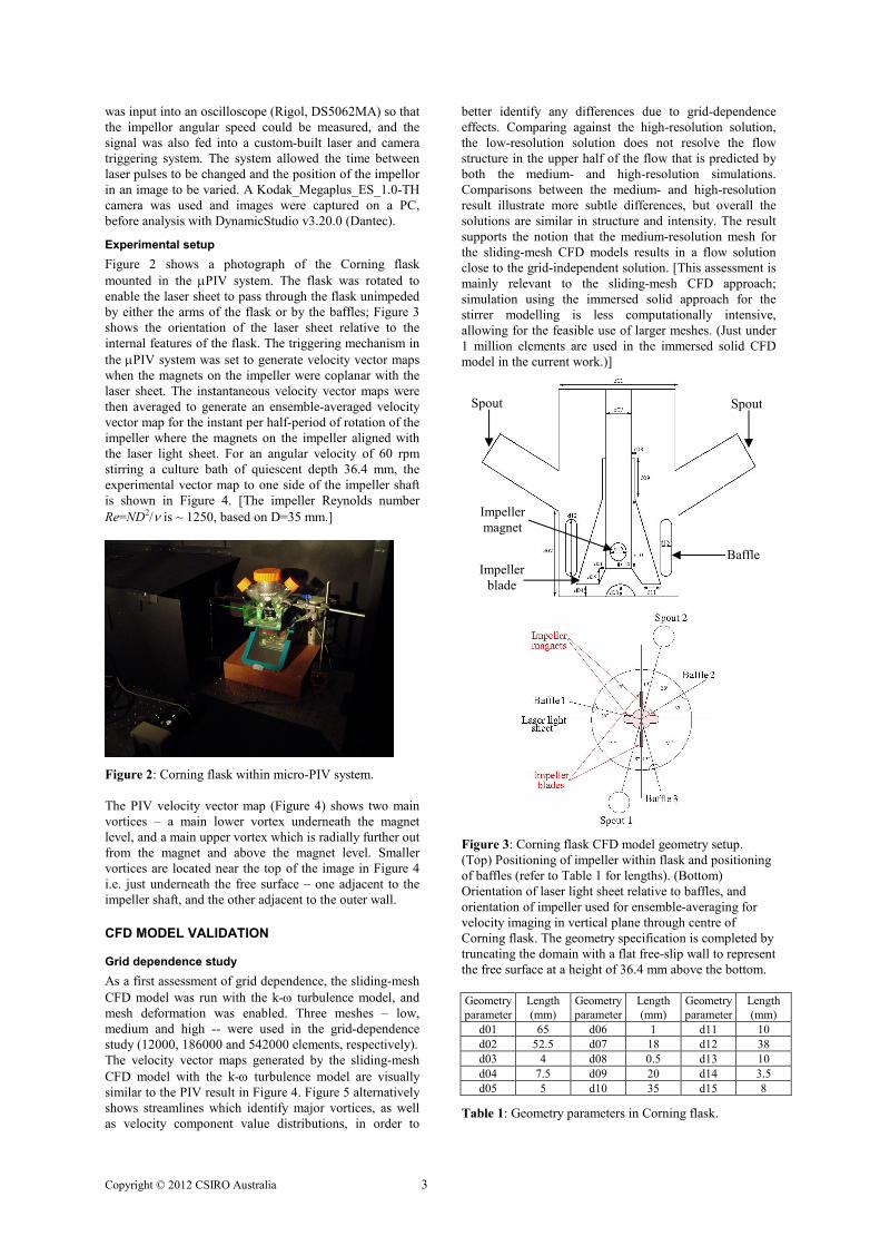
Experimental setup
Figure 2 shows a photograph of the Corning flask
mounted in the µPIV system. The flask was rotated to
enable the laser sheet to pass through the flask unimpeded
by either the arms of the flask or by the baffles; Figure 3
shows the orientation of the laser sheet relative to the
internal features of the flask. The triggering mechanism in
the µPIV system was set to generate velocity vector maps
when the magnets on the impeller were coplanar with the
laser sheet. The instantaneous velocity vector maps were
then averaged to generate an ensemble-averaged velocity
vector map for the instant per half-period of rotation of the
impeller where the magnets on the impeller aligned with
the laser light sheet. For an angular velocity of 60 rpm
stirring a culture bath of quiescent depth 36.4 mm, the
experimental vector map to one side of the impeller shaft
is shown in Figure 4. [The impeller Reynolds number
Re=ND2/ν is ~ 1250, based on D=35 mm.]
Figure 2: Corning flask within micro-PIV system.
The PIV velocity vector map (Figure 4) shows two main
vortices – a main lower vortex underneath the magnet
level, and a main upper vortex which is radially further out
from the magnet and above the magnet level. Smaller
vortices are located near the top of the image in Figure 4
i.e. just underneath the free surface – one adjacent to the
impeller shaft, and the other adjacent to the outer wall.
CFD MODEL VALIDATION
Grid dependence study
As a first assessment of grid dependence, the sliding-mesh
CFD model was run with the k-ω turbulence model, and
mesh deformation was enabled. Three meshes – low,
medium and high -- were used in the grid-dependence
study (12000, 186000 and 542000 elements, respectively).
The velocity vector maps generated by the sliding-mesh
CFD model with the k-ω turbulence model are visually
similar to the PIV result in Figure 4. Figure 5 alternatively
shows streamlines which identify major vortices, as well
as velocity component value distributions, in order to
better identify any differences due to grid-dependence
effects. Comparing against the high-resolution solution,
the low-resolution solution does not resolve the flow
structure in the upper half of the flow that is predicted by
both the medium- and high-resolution simulations.
Comparisons between the medium- and high-resolution
result illustrate more subtle differences, but overall the
solutions are similar in structure and intensity. The result
supports the notion that the medium-resolution mesh for
the sliding-mesh CFD models results in a flow solution
close to the grid-independent solution. [This assessment is
mainly relevant to the sliding-mesh CFD approach;
simulation using the immersed solid approach for the
stirrer modelling is less computationally intensive,
allowing for the feasible use of larger meshes. (Just under
1 million elements are used in the immersed solid CFD
model in the current work.)]
Figure 3: Corning flask CFD model geometry setup.
(Top) Positioning of impeller within flask and positioning
of baffles (refer to Table 1 for lengths). (Bottom)
Orientation of laser light sheet relative to baffles, and
orientation of impeller used for ensemble-averaging for
velocity imaging in vertical plane through centre of
Corning flask. The geometry specification is completed by
truncating the domain with a flat free-slip wall to represent
the free surface at a height of 36.4 mm above the bottom.
Geometry
parameter
Length
(mm)
Geometry
parameter
Length
(mm)
Geometry
parameter
Length
(mm)
d01 65 d06 1 d11 10
d02 52.5 d07 18 d12 38
d03 4 d08 0.5 d13 10
d04 7.5 d09 20 d14 3.5
d05 5 d10 35 d15 8
Table 1: Geometry parameters in Corning flask.
Spout
Impeller
magnet
Spout
Baffle Impeller
blade

Copyright © 2012 CSIRO Australia 4
Figure 4: Experimental ensemble-averaged velocity vector
map at laser light sheet location shown in Figure 3,
generated by the µPIV system for the case of 60 rpm
impeller speed. The reference vector magnitude (bottom of
plot) is 20 mm/s.
Comparison with µµµµPIV data
In comparison to the experimental result in Figure 4, the
streamlines shown in Figure 5, at first glance, capture the
lower vortex and the mid-level near-magnet vortex quite
well. Some attempt is made in that sliding-mesh k-ω
model to capture the vortical structure high up in the flask
liquid, but its extent seems well overpredicted. It would
appear that this large-upper-vortex prediction is unique to
the combination of the k-ω model with the sliding mesh
method, with the other CFD models tested failing to
capture any vortical structures above the mid-level vortex,
instead predicting largely laminar flow. The result shown
in Figure 6(c), where the k-ω model is used but the stirrer
modelling is done using the immersed solid method, is
intriguing because the differences between Figures 6(a)
and 6(c) are solely due to the use of the immersed-solid
method in preference to the sliding-mesh method.
Comparison with the PIV data shows that no single CFD
model tested in the work achieved full correspondence in
all vortical structures in the laser light sheet plane, but that
all the CFD models do capture the two main vortices
shown in Figure 4. A first assessment of the relative
quality of CFD models for the Corning stirred-flask uses
the distance of the relevant vortex centre away from the
vortex centre locations seen in the PIV. Table 2 shows the
immersed solid CFD model to get quite close to the main
mid-level vortex. Another assessment of the relative
quality of the CFD models is based on velocity profiles.
For valid comparison given the difference in the locations
of the vortex centres between models, the lines along
which the profiles are extracted are placed to pass through
the vortex centre locations captured in each model. Figure
7 shows that the models pick up the general trends in
velocity profiles moving away from the vortex centres, but
with larger errors well away from the vortex centres as
differences in flow structure between models become more
pronounced. Overall for the velocity variation behaviour
between the local extrema in velocity either side of the
relevant major vortex, the immersed solid CFD model
seems to be able to best represent the PIV data.
Figure 5: Results of grid-dependence study using the
sliding-mesh CFD model of the Corning stirred-flask and
the k-ω turbulence model, for the flow field in the plane of
the PIV light sheet: (left column) streamlines; (middle
column) u-velocity component; (right column) w-velocity
component; (top row) low-resolution mesh; (middle row)
medium-resolution mesh; (bottom row) high-resolution
mesh.
Comparison with the PIV data shows that no single
approach tested in this work does an acceptable job of
capturing the flow structure just underneath the free
surface. Even though the 60 rpm stirrer speed does not
cause substantial free surface deformation, the ability of
the free surface to accommodate even slight deformation is
known to be important in modifying turbulence structure
due to interface/turbulence interactions. As such, CFD
models with rigid free-surface representations should not
be expected to capture or impose the correct near-interface
turbulence asymptotics. Proceeding in this work with the
immersed solid CFD model of the Corning stirred flask, it
is worth noting that immersed solid model cannot be used
in conjunction with the multiphase flow modelling in
CFX. Until this situation is corrected in future CFX
releases, it is uncertain whether any of the existing CFX
models tested in this work can be modified adequately to
correctly capture the near-free-surface vortices seen in the
PIV result in Figure 4.
FLOW ANALYSIS
Shear stress, Kolmogorov length scale
For CFD models featuring eddy viscosity-based
turbulence models, the shear stress experienced by a
microcarrier particle at any location is approximated as
τ = (µ+µT)|S| , (1)
while the Kolmogorov length scale is computed as
lk = (µ3/(ρ3ε))1/4 . (2)
Figure 8(a) shows the shear stress distribution in the PIV
light sheet at an instant when the magnets are aligned with
the light sheet. It turns out that the magnet ends are the
locations in the entire flow featuring the highest shear
stress levels at this instant in time. This is not surprising
since the magnet protrudes out further than the blades of
the impeller. While the magnet ends are also regions of
high turbulence as denoted by locally low values of lk
(hence high turbulence dissipation), the global minimum
value of lk is actually on the baffle surface. In the instant
shown in Figure 8, the global minimum for lk is 75 µm.
[m]
[m]
20 mm/s
Impeller magnet

Copyright © 2012 CSIRO Australia 5
Figure 6: Predicted ensemble-averaged velocity vector
maps in plane of PIV light sheet: (a) sliding mesh,
medium-res, k-ω model; (b) sliding mesh, medium-res,
BSL-RSM model; (c) immersed solid, high-res, k-ω
model. The vector map in Figure 4 is the appropriate
experimental comparison.
During operation of the Corning stirrer-flask according to
protocols to achieve particle suspension, the minimum
Kolmogorov length scale will typically be lowest when an
impeller magnet passes a baffle. Larger regions of
relatively low lk (less than 125 µm) occur in the wakes of
the impeller blades. The lk in the wakes of the impeller
blades may be more important than the global minimum.
This is because most microcarrier particles will pass
through the impeller blade wakes during a protocol where
impeller motion only occurs periodically to induce particle
suspension, while fewer particles will pass in close
proximity to the tip of the impeller magnet.
Case Vortex
Centre
x-coord
Vortex
Centre
y-coord
Distance
from PIV
vortex centre
Main Lower Vortex
PIV -18.2 13.9
No turbulence model -19.5 7.2 6.8
k-ω -19.1 7.2 6.8
BSL-RSM -19.0 8.5 5.5
LES-WALE -18.3 7.7 6.2
ImmSol k-ω -22.3 8.4 6.8
Main Upper Vortex
PIV -28.0 29.6
No turbulence model -25.7 19.5 10.4
k-ω -26.1 18.1 11.7
BSL-RSM -26.1 22.7 7.2
LES-WALE -25.7 21.8 8.1
ImmSol k-ω -23.6 27.8 4.8
Table 2: Locations of vortex centres in plane of PIV light
sheet generated by different transient CFD models of the
Corning stirred-flask. (Black data: sliding mesh method;
grey data: immersed solid (ImmSol) method.) [mm units.]
(a) v-velocity in horizontal line
through main lower vortex
(b) u-velocity in vertical line
through main lower vortex
(c) v-velocity in horizontal line
through main upper vortex
(d) u-velocity in vertical line
through main upper vortex
Figure 7: Velocity component magnitude profiles vector
maps in plane of PIV light sheet generated by transient
CFD models of the Corning stirred-flask: ×××× PIV;
sliding-mesh + no turbulence model (MILES); - ⋅ - ⋅ -
sliding-mesh + k-ω; sliding-mesh + BSL-RSM; - - -
sliding-mesh + LES-WALE; - - - immersed-solid + k-ω.
Turbulence, cell damage and microcarrier suspension
The results in Figure 8 feature shear stress and
Kolmogorov length scale magnitudes similar to those
featured in the microcarrier-based suspension bioreactor
literature. The most interesting of these results is from
Croughan et al. (1987) regarding the dependence of the
relative cell growth on lk, in which the growth of human
FS-4 cells varied abruptly with lk, from 100% growth at lk
> 135 µm, down to 60% growth at lk ≈ 115 µm, 20%
growth at lk ≈ 100 µm, and ultimately zero growth at lk ≈
90 µm. For the time instant shown in Figure 8(b), it is
apparent that half of the flow plane at magnet level will
feature some inhibition of cell expansion, but substantial
inhibition occurs in only the small proportion (5-10 %) of
the flow plane that is in the wakes of the magnets and the
impeller blades.
(a)
(b)
(c)
20 mm/s
20 mm/s
20 mm/s
[m]
[m]
[m]
[m]
[m]
[m]
Impeller magnet
Impeller magnet
Impeller magnet

Copyright © 2012 CSIRO Australia 6
Figure 8: Distribution acting on microcarrier particle
surfaces by the fluid flow during operation of the Corning
stirred-flask at 60 rpm, as predicted by the immersed solid
CFD model in the plane 20 mm above the flask base
(magnet level) at one instant of the operation: (a) shear
stress; (b) Kolmogorov length scale.
Figure 9: Sample evolution of particle suspension to
firstly achieve a just-suspended state, and then to a more
homogenized state upon entrainment of particles into the
flow structures. [Impeller location shown at t = 6.4s.]
A true time- and volume-averaged measure of the relative
cell growth depends on microcarrier history tracking, and
logging to tally the stress exposures as the microcarriers
pass through different parts of the flow. A first clue to the
effect of flask spin-up on potential stem cell death is given
in Figure 9, generated by adding Lagrangian particle
tracking into the immersed solid CFD model. [This result
is only for qualitative illustrative purposes, given the
current capability of CFX to correctly model particle
interactions with the immersed solid representation of the
stirrer is unproven.] The frames in Figure 9 indicate that
spin-up to achieve full suspension throws the particles into
the high-stress zones in the wakes of the magnets and
impeller blades, but that particles later move out of the
high-stress zones as the particle distribution stabilizes in
the mean stirrer-driven flow. The short time exposure of
the majority of the microcarrier population to these
regions may spare wholesale cell damage. For quality-
control purposes and for avoiding lineage control
problems, however, the evidence of interaction of a
significant proportion of the microcarrier population with
the high-stress regions in Figure 8 is of some concern.
CONCLUSION
The paper presents a CFD model that is shown to be a
realistic model of the hydrodynamics within a Corning
stirred-flask. The CFD models feature room for
improvement through targeted improvements to
turbulence modelling, stirrer motion modelling and free
surface modelling. The work shows CFD to be useful in
identifying possibilities for microcarrier exposure to
regions of stress levels that could cause cell damage and
stem cell differentiation issues. As such, CFD shows
promise for use as risk-mitigation tool prior to
commissioning protocols used in for stem-cell bioreactors.
ACKNOWLEDGEMENTS
This work was supported by the Biomedical Materials and
Devices Theme of CSIRO Materials Science and
Engineering (CMSE).
REFERENCES
ALLEGRUCCI, C., and YOUNG, L.E., (2007),
“Differences between human embryonic stem cell lines”,
Hum. Reprod. Update, 13, 103-120.
CORMIER, J.T., ZUR NIEDEN, N.I., RANCOURT,
D.E., and KALLOS, M.S., (2006), “Expansion of
undifferentiated murine embryonic stem cells as
aggregates in suspension culture bioreactors”, Tissue Eng.,
12, 3233-3245.
CROUGHAN, M.S., HAMEL, J.-F., and WANG,
D.I.C., (1987), “Hydrodynamic effects on animal cells
grown in microcarrier cultures”, Biotech. Bioengrg., 29,
130-141.
GLOSSOP, J.R., and CARTMELL, S.H., (2009),
“Effect of fluid flow-induced shear stress on human
mesenchymal stem cells: differential gene expression of
IL1B and MAP3K8 in MAPK signaling”, Gene Expr.
Patterns, 9, 381-388.
HEWITT, C.J., LEE, K., NIENOW, A.W., THOMAS,
R.J., SMITH, M., and THOMAS, C.R., (2011),
“Expansion of human mesenchymal stem cells on
microcarriers”, Biotechnol. Lett., 33, 2325-2335.
LIOVIC, P., LAKEHAL, D., (2007), “Multi-physics
treatment in the vicinity of arbitrarily deformable gas-
liquid interfaces”, J. Comput. Phys., 222, 504-535.
SHAFA, M., KRAWETZ, R., ZHANG, Y., RATTNER,
J.B., GODOLLEI, A., DUFF, H., and RANCOURT, D.E.,
(2011), “Impact of stirred suspension bioreactor culture on
the differentiation of murine embryonic stem cells into
cardiomyocytes”, BMC Cell Biol., 12, 53-64.
YEATTS, A.B., CHOQUETTE, D.T., and FISHER,
J.P., (2012), “Bioreactors to influence stem cell fate:
augmentation of mesenchymal stem cell signalling
pathways via dynamic culture systems”, Biochimica
Biophysica Acta, in press.
ZHANG, H., DAI, S., BI, J., and LIU, K.-K., (2011),
“Biomimetic three-dimensional microenvironment for
controlling stem cell fate”, Interface Focus., 1, 792-803.
ZHANG, H., KAY, A., FORSYTH, N.R., LIU, K.-K.,
and EL HAJ, A.J., (2012), “Gene expression of single
human mesenchymal stem cell in response to fluid shear”,
J. Tissue. Eng., 3 (1), 2041731412451988.
(a)
(b)
t = 2.0 s t = 3.0 s
t = 4.0 s t = 6.0 s