fluent analysis of exhaust manifold with different flow rates · fluent analysis of exhaust...
TRANSCRIPT
Page 7
Fluent Analysis of Exhaust Manifold with Different Flow Rates
S.Sumalatha
Department of Mechanical Engineering,
Sri Vaishnavi College of Engineering,
Srikakulam, A.P - 532185, India.
K. Srinivasa Rao
Department of Mechanical Engineering,
Sri Vaishnavi College of Engineering,
Srikakulam, A.P - 532185, India.
ABSTRACT
Exhaust manifold is one of the most critical
components of an IC Engine. The designing of exhaust
manifold is a complex procedure and is dependent on
many parameters viz. back pressure, exhaust velocity,
mechanical efficiency etc. Preference for any of this
parameter varies as per designers needs. Usually fuel
economy, emissions and power requirement are three
different streams or thought regarding exhaust
manifold design. In any multi-cylinder IC engine, an
exhaust manifold (also known as a header) collects the
exhaust gases from multiple cylinders into one
pipe.This header is connected to these cylinders
through bends. It is attached downstream of the engine
and is major part in multi‐ cylinder engines where
there are multiple exhaust streams that have to be
collected into a single pipe.Exhaust gases comes out of
this Header as a single stream of hot exhaust gases
through single outlet. This work comprehensively
analyzes eight different models of exhaust manifold
and concludes the best possible design for least
emissions and complete combustion of fuel to ensure
least pollution. The main objective of this investigation
is to design an exhaust manifold by using CATIA V5
R20 software and also find out pressures and velocities
at various mass flow rates in the exhaust manifolds
with Long Bend Side Exit (LBSE), Long Bend Middle
Exit (LBME) and Reducer and find out the
performance of the exhaust manifold with various
modifications in its design or adding a component for
the exhaust manifold to increase its effectiveness. In
the current analysis mass flow rates considered in the
exhaust manifold are 2 kg/s, 4 kg/s, 6 kg/s, 8 kg/s ,10
kg/s, 12 kg/s in all the various modification ns in the
exhaust manifolds.
Key words: Manifold, IC Engine, LBME, LBSE.
1. INTRODUCTION
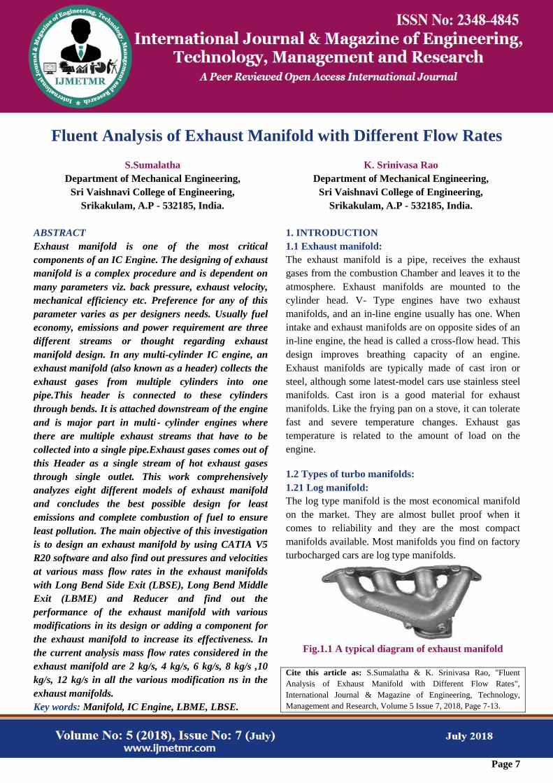
1.1 Exhaust manifold:
The exhaust manifold is a pipe, receives the exhaust
gases from the combustion Chamber and leaves it to the
atmosphere. Exhaust manifolds are mounted to the
cylinder head. V- Type engines have two exhaust
manifolds, and an in-line engine usually has one. When
intake and exhaust manifolds are on opposite sides of an
in-line engine, the head is called a cross-flow head. This
design improves breathing capacity of an engine.
Exhaust manifolds are typically made of cast iron or
steel, although some latest-model cars use stainless steel
manifolds. Cast iron is a good material for exhaust
manifolds. Like the frying pan on a stove, it can tolerate
fast and severe temperature changes. Exhaust gas
temperature is related to the amount of load on the
engine.
1.2 Types of turbo manifolds:
1.21 Log manifold:
The log type manifold is the most economical manifold
on the market. They are almost bullet proof when it
comes to reliability and they are the most compact
manifolds available. Most manifolds you find on factory
turbocharged cars are log type manifolds.
Fig.1.1 A typical diagram of exhaust manifold
Cite this article as: S.Sumalatha & K. Srinivasa Rao, "Fluent
Analysis of Exhaust Manifold with Different Flow Rates",
International Journal & Magazine of Engineering, Technology,
Management and Research, Volume 5 Issue 7, 2018, Page 7-13.
Page 8
This is understandable when you manufacturer is all
about reliability. When it comes to performance, a log
manifold will leave you wanting. This hurts the turbo‘s
performance and hurts the motors performance as well
being that a log manifolds common plenum is so close to
the other cylinders, it causes a lot of back flow of
exhaust.
2. Literature Survey
Analyzed the performance of the manifolds with a
tapered longitudinal section. [1]
In their research paper they had applied a multi-
disciplinary optimization approach for the exhaust
system, exhaust manifold and catalytic converter, in
highly integrated concurrent engineering software
framework. [2]
In their research they had employed numerical
simulations (CFD methods) for estimating the flow loss
coefficient in manifolds. [3]
In their research paper they have developed a multi-
objective optimization method for the exhaust manifold
by using Divided Range Multi objective Genetic
Algorithm. [4]
In their research paper they used GT-Power, 1-
dimensional software, for estimating the engine
performance of a single cylinder IC engine. [5]
Designing Exhaust Manifolds Using Integral
Engineering Solutions‖ focused on the development of a
reliable approach to predict failure of exhaust manifolds
and on the removal of structural weaknesses through the
optimization of design. [6]
In their paper they had performed CFD analysis to
estimate the performance of the exhaust manifold while
placing the catalytic converter near to it (Close-Coupled
Catalytic Converter). [7]
In this research paper he conducted CFD simulations on
manifold of direct injection diesel engine. They had used
the RANS (Reynolds Averaged Navier Stokes) solver
approach with RNG k-ε turbulence model for the
simulations. The flow inlet for the manifolds was
modeled using ‗pressure-inlet.[8]
In his research paper they had applied CFD methods to
identify the optimum exhaust manifold for a 4-stroke 4-
cylinder SI engine.[9]
In this paper they had developed an exhaust system heat
transfer model that included the steady state and
transient heat conduction as well as convection and
radiation.[10]
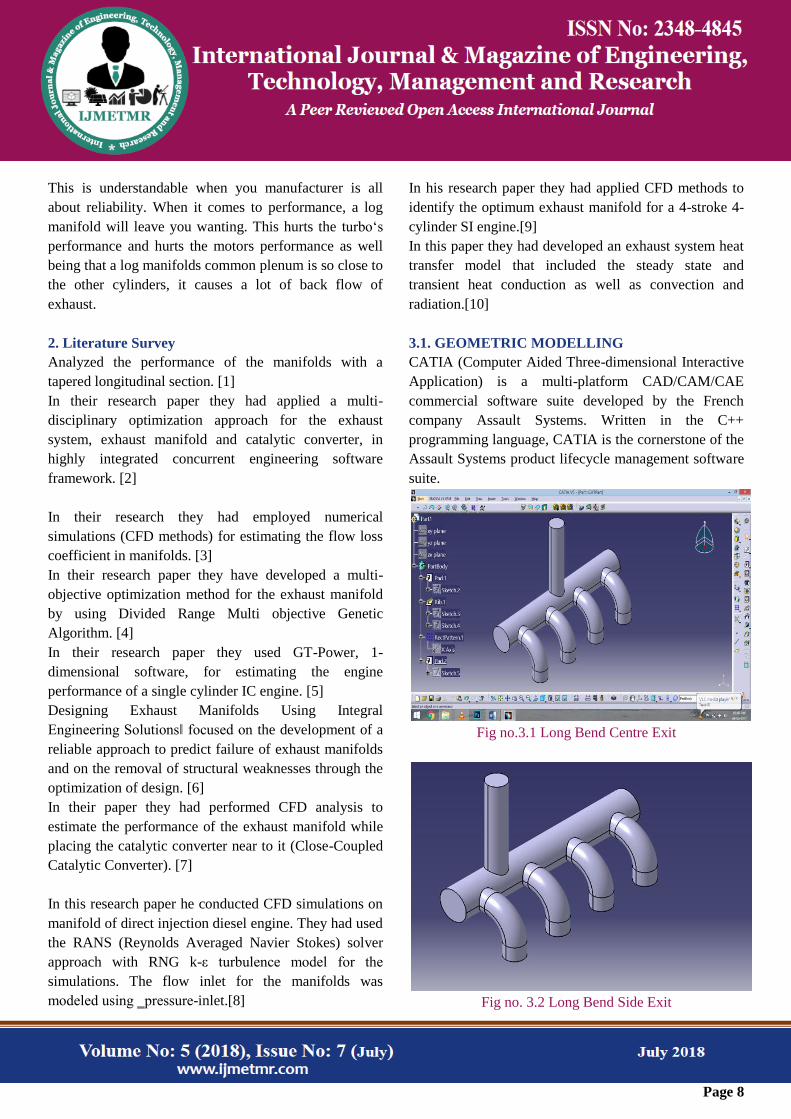
3.1. GEOMETRIC MODELLING
CATIA (Computer Aided Three-dimensional Interactive
Application) is a multi-platform CAD/CAM/CAE
commercial software suite developed by the French
company Assault Systems. Written in the C++
programming language, CATIA is the cornerstone of the
Assault Systems product lifecycle management software
suite.
Fig no.3.1 Long Bend Centre Exit
Fig no. 3.2 Long Bend Side Exit
Page 9
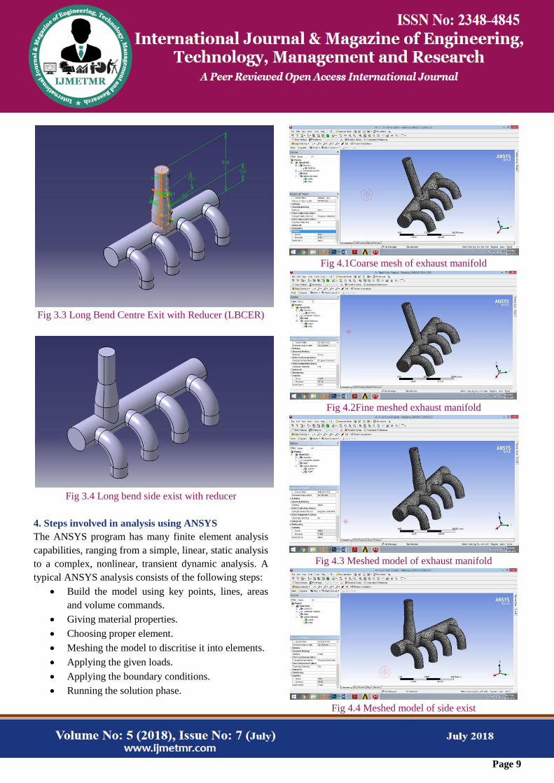
Fig 3.3 Long Bend Centre Exit with Reducer (LBCER)
Fig 3.4 Long bend side exist with reducer
4. Steps involved in analysis using ANSYS
The ANSYS program has many finite element analysis
capabilities, ranging from a simple, linear, static analysis
to a complex, nonlinear, transient dynamic analysis. A
typical ANSYS analysis consists of the following steps:
Build the model using key points, lines, areas
and volume commands.
Giving material properties.
Choosing proper element.
Meshing the model to discritise it into elements.
Applying the given loads.
Applying the boundary conditions.
Running the solution phase.
Fig 4.1Coarse mesh of exhaust manifold
Fig 4.2Fine meshed exhaust manifold
Fig 4.3 Meshed model of exhaust manifold
Fig 4.4 Meshed model of side exist
Page 10
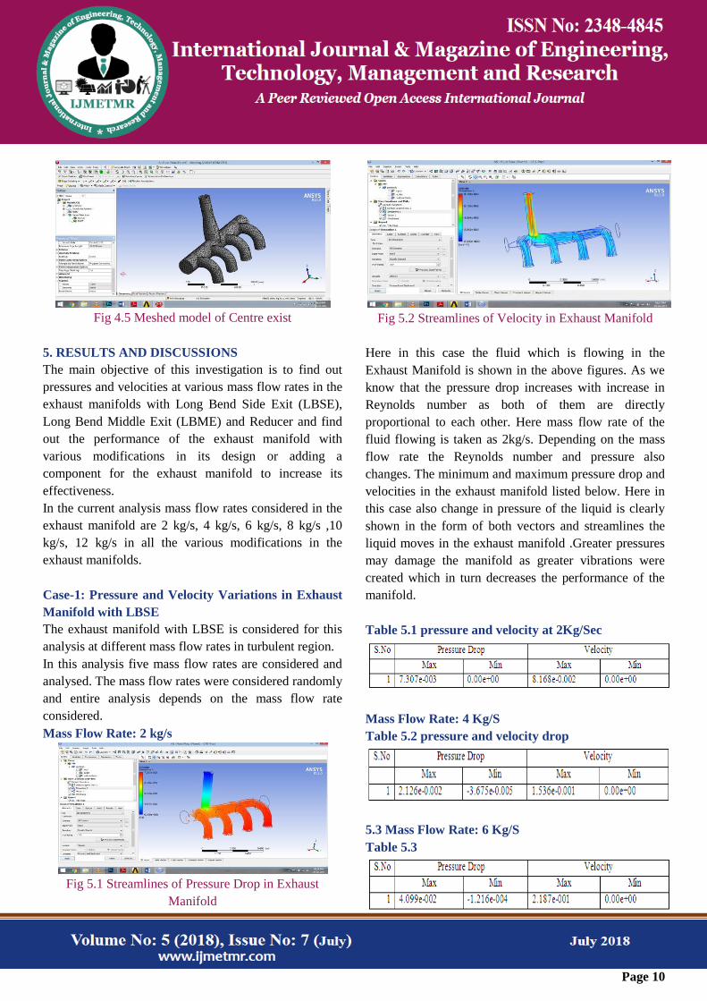
Fig 4.5 Meshed model of Centre exist
5. RESULTS AND DISCUSSIONS
The main objective of this investigation is to find out
pressures and velocities at various mass flow rates in the
exhaust manifolds with Long Bend Side Exit (LBSE),
Long Bend Middle Exit (LBME) and Reducer and find
out the performance of the exhaust manifold with
various modifications in its design or adding a
component for the exhaust manifold to increase its
effectiveness.
In the current analysis mass flow rates considered in the
exhaust manifold are 2 kg/s, 4 kg/s, 6 kg/s, 8 kg/s ,10
kg/s, 12 kg/s in all the various modifications in the
exhaust manifolds.
Case-1: Pressure and Velocity Variations in Exhaust
Manifold with LBSE
The exhaust manifold with LBSE is considered for this
analysis at different mass flow rates in turbulent region.
In this analysis five mass flow rates are considered and
analysed. The mass flow rates were considered randomly
and entire analysis depends on the mass flow rate
considered.
Mass Flow Rate: 2 kg/s
Fig 5.1 Streamlines of Pressure Drop in Exhaust
Manifold
Fig 5.2 Streamlines of Velocity in Exhaust Manifold
Here in this case the fluid which is flowing in the
Exhaust Manifold is shown in the above figures. As we
know that the pressure drop increases with increase in
Reynolds number as both of them are directly
proportional to each other. Here mass flow rate of the
fluid flowing is taken as 2kg/s. Depending on the mass
flow rate the Reynolds number and pressure also
changes. The minimum and maximum pressure drop and
velocities in the exhaust manifold listed below. Here in
this case also change in pressure of the liquid is clearly
shown in the form of both vectors and streamlines the
liquid moves in the exhaust manifold .Greater pressures
may damage the manifold as greater vibrations were
created which in turn decreases the performance of the
manifold.
Table 5.1 pressure and velocity at 2Kg/Sec
Mass Flow Rate: 4 Kg/S
Table 5.2 pressure and velocity drop
5.3 Mass Flow Rate: 6 Kg/S
Table 5.3
Page 11
Mass Flow Rate: 8Kg/s
Table 5.4 Pressure and velocity drop calculations
Mass Flow Rate:10 Kg/s
Table 5.5 pressure and velocity drop
Mass Flow Rate:12 Kg/s
Table 5.6 pressure and velocity drop
Case-2: Pressure and Velocity Variations in Exhaust
Manifold with LBCE
The exhaust manifold with LBCE is considered for this
analysis at different mass flow rates in turbulent region.
In this analysis five mass flow rates are considered and
analyzed. The mass flow rates were considered
randomly and entire analysis depends on the mass flow
rate considered.
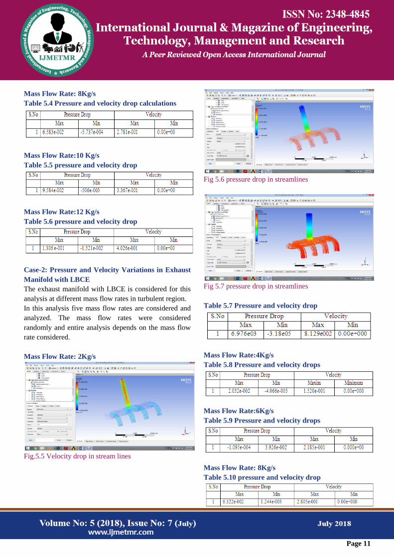
Mass Flow Rate: 2Kg/s
Fig.5.5 Velocity drop in stream lines
Fig 5.6 pressure drop in streamlines
Fig 5.7 pressure drop in streamlines
Table 5.7 Pressure and velocity drop
Mass Flow Rate:4Kg/s
Table 5.8 Pressure and velocity drops
Mass Flow Rate:6Kg/s
Table 5.9 Pressure and velocity drops
Mass Flow Rate: 8Kg/s
Table 5.10 pressure and velocity drop
Page 12
Mass Flow Rate:10 Kg/s
Table 5.11 Pressure and velocity drops
Mass Flow Rate: 12 Kg/s
Table 5.12 Pressure and velocity drops
Case-3: Pressure and Velocity Variations in Exhaust
Manifold with Reducer
The exhaust manifold with reducer is considered for this
analysis at different mass flow rates in turbulent region.
In this analysis five mass flow rates are considered and
analysed. The mass flow rates were considered randomly
and entire analysis depends on the mass flow rate
considered.
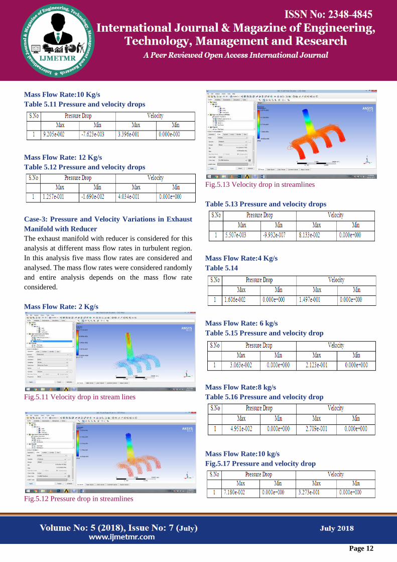
Mass Flow Rate: 2 Kg/s
Fig.5.11 Velocity drop in stream lines
Fig.5.12 Pressure drop in streamlines
Fig.5.13 Velocity drop in streamlines
Table 5.13 Pressure and velocity drops
Mass Flow Rate:4 Kg/s
Table 5.14
Mass Flow Rate: 6 kg/s
Table 5.15 Pressure and velocity drop
Mass Flow Rate:8 kg/s
Table 5.16 Pressure and velocity drop
Mass Flow Rate:10 kg/s
Fig.5.17 Pressure and velocity drop
Page 13
Mass Flow Rate: 12 kg/s
Fig.5.18 Pressure and velocity drop
6. CONCLUSION
In this thesis the investigation is to find out pressures
and velocities at various mass flow rates in the exhaust
manifolds with Long Bend Side Exit (LBSE), Long
Bend Middle Exit (LBME) and Reducer and find out the
performance of the exhaust manifold with various
modifications in its design or adding a component for
the exhaust manifold to increase its effectiveness.
In the current analysis mass flow rates considered in the
exhaust manifold are 2 kg/s, 4 kg/s, 6 kg/s, 8 kg/s ,10
kg/s, 12 kg/s in all the various modifications in the
exhaust manifolds.
From the above investigations it is found that Long Bend
Middle Exit (LBME) with Reducer is giving the better
performance.
7 References
[1] Jafar M. Hassan, Wahid S. Mohammed,Thamer
A.Mohamed,Wissam H. Alawee, ―CFD Simulation for
Manifold with Tapered longitudinal
Section‖,International Journal of Emerging Technology
and Advanced Engineering Volume 4, Issue
2,February2014.
[2] Nikhil Kanawade, Omkar Siras, ―Design, Analysis
and Development of 4-Cylinder IC Engine Exhaust
Manifold‖, International Engineering Research Journal
Page No 472-478.
[3] Mohd Sajid Ahmed, Kailash B A, Gowreesh,
―DESIGN AND ANALYSIS OF A
MULTICYLINDER FOUR STROKE SI ENGINE
EXHAUST MANIFOLD USING CFD TECHNIQUE‖,
International Research Journal of Engineering and
Technology (IRJET) e-ISSN: 2395-0056.
[4] Kanupriya Bajpai,Akash Chandrakar,
AkshayAgrawal,Shiena Shekhar, ―CFD Analysis of
Exhaust Manifold of SI Engine and Comparison of Back
Pressure using Alternative Fuels‖, IOSR Journal of
Mechanical and Civil Engineering
(IOSRJMCE),Volume 14, Issue1Ver. I (Jan.-Feb. 2017).
[5] K. Nanthagopal, B. Ashok,R. Thundil Karuppa Raj,
―Design considerations and overview of an engine
exhaust manifold gasket‖, Journal of Chemical and
Pharmaceutical Sciences ISSN: 0974-2115.
[6] Vivekanand Navadagi, Siddaveer Sangamad, ―CFD
Analysis of Exhaust Manifold of Multi- Cylinder Petrol
Engine for Optimal Geometry to Reduce Back Pressure‖,
International Journal of Engineering Research &
Technology Vol. 3 - Issue 3 (March - 2014).
[7] K.S.Umesh ,V.K. Pravin and K. Rajagopal
―Experimental Investigation of Various Exhaust
Manifold Designs and Comparison of Engine
Performance Parameters for These to Determine Optimal
Exhaust Manifold Design for Various Applications‖,
Proc. of Int. Conf. on Advances in Mechanical
Engineering, AETAME
[8] Gopaal, M M M Kumara Varma, Dr. L Suresh
Kumar, ―thermal and structural analysis of an exhaust
manifold of a multi cylinder engine‖, international
journal of mechanical engineering and technology
(ijmet) issn 0976 – 6340.
[9] k. S. Umesh, v. K. Pravin& k. Rajagopal, ―cfd
analysis of exhaust manifold of multi-cylinder si engine
todetermine optimal geometry for reducing emissions‖,
International Journal of Automobile Engineering ISSN
2277-4785Vol. 3, Issue 4, Oct 2013, 45-56.
[10] Jae Ung Cho, ―A Study on Flow Analysis of the
Exhaust Manifold for Automobile‖, International Journal
of Applied Engineering Research ISSN 0973-4562
Volume 11, Number 2 (2016).