flowmaster ii rotary driven electric pump, 24 v dc ii rotary driven electric pump includesa motor...
TRANSCRIPT

FlowMaster II rotary driven electric pump, 24 V DCModel 85728, series “A”Model 85729, series “A”Model 85730, series “A”
Installation and maintenance guide
Date of issue May 2013
Form number 404443
Section C8
Page 356B

SafetyRead and carefully observe these operating instructions before unpacking and operating the pump! The pump must be operated, maintained and repaired exclusively by per-sons familiar with the operating instructions. Local safety regulations regarding installa-tion, operation and maintenance must be followed.
Operate this pump only after safety in-structions and this service manual are fully understood.
DescriptionGeneral description
Models 85728, 85729 and 82730 are pumping units designed to operate a Cen-tro-Matic lubrication system. The units include a vent valve to relieve the line pres-sure to recharge the injectors. FlowMaster II rotary driven electric pump includesa motor speed control and built in circuit protection to prevent control burnout.
The FlowMaster II pump is fully automatic when used with Model 85530 Controller and a pressure switch. The FlowMaster II pump is double acting, dispensing lubricant on both the “up” and “down” strokes. This unit is designed to be used with SL-V, SL-1, SL-11, SL-32 and SL33 series injectors or a combination of these.
Models 85728, 85729 and 82730 include follower plate and mechanical low level indicator. Model 82730 also includes an electrical high level switch to indicate when reservoir is full.
Appropriate use• The pump on this unit is exclusively
designed to pump and dispense lubricants using electric power only.
• The maximum specification ratings should not be exceeded.
• Any other use not in accordance with in-structions will result in loss of claims for warranty and liability.
Table of contents
Safety . . . . . . . . . . . . . . . . . . . . . . . . . 2
Specifications . . . . . . . . . . . . . . . . . . . 2
Description . . . . . . . . . . . . . . . . . . . . . 2
System operation . . . . . . . . . . . . . . . . 3
Installing the pump. . . . . . . . . . . . . . . 3
Putting pump into operation . . . . . . . 3
Maintenance & repair . . . . . . . . . . . . . 3
Dimensions . . . . . . . . . . . . . . . . . . . . . 6
Repair parts list . . . . . . . . . . . . . . . . . 10
Troubleshooting . . . . . . . . . . . . . . . . . 11
Indicates a hazardous situation which, if not avoided will result in death or seri-ous injury. Please refer to the 85737 and 85738 pump operation manual, section C8, page 353, series for all oth-er safety considerations
Warn ingProduct specification
Supply voltage 24 V DCAmbient operating temperature –40 to +150 °F (–40 to +66 °C)Container capacity
85728 60 lbs. (27 kg)8572985730 120 lbs. (57 kg)
90 lbs. (41 kg)
Do not exceed an outlet grease pressure of 4,000 psi (276 bar)
Do not exceed 3,000 psi (207 bar) max-imum supply inlet electric pressure or 3,500 psi (241 bar) maximum outlet pressure. Exceeding the rated pressures may result in damage to system compo-nents and personal injury.
Warn ing
2

System operation Operation with model 85530 system controller
When model 85530 times out, it will initiate a lube cycle. The solenoid is energized to deliver electric pressure to the pump and vent valve. The pump begins dispensing lubricant through injectors to the bearings.
When all bearings have received lubri-cant, pressure rises in the system to actuate the pressure switch. When pressure switch actuates, the control is reset to de–energize the solenoid valve cutting off electric oil pressure to the pump and vent valve. Pump stops, pressure vents and pressure switch de–actuates. Control begins timing toward next lube event.
Installing the pumpPlace the unit in the approximate location making sure that electric power connections are accessible. Mark center locations of the holes at the bottom of the reservoir. For models 85728 and 85729 drill six 1/2 in. (13 mm) holes. The use of 7/16 in. (10 mm) bolts will offer some flexibility in securing the reservoir to the equipment. For model 85730 drill four 5/8 in. (15 mm) holes. The use of 1/2 in. (12 mm) bolts will offer some flexibility in securing the reservoir to the equipment.
Lubricant outlet of pump should be con-nected to system with suitable hose capable of 3,500 psi (241 bar) working pressure. Be careful to connect the red electric motor lead to the positive side of the circuit. The motor is polarity sensitive and will not run if wired incorrectly. Wire the pump motor and vent valve as shown in fig. 1 and 2.
Please refer to the 85737 and 85738 op-eration manual, section C8, page 353, series for setting the pump control on the 24 V DC motor.
Putting pump into operationFilling reservoir• To bulk fill the reservoir, remove the lower
and upper pipe plugs from the side of the reservoir. Attach the appropriate bulk-fill-ing pump to the lower inlet (1 NPT). Fill reservoir until grease appears at the top 1 1/4 NPT vent high level port. Remove the bulk filling pump. Replace both pipe plugs.
Maintenance and repairGeneral maintenance• Keep area around pump clean. Clean off
filling port area prior to filling reservoir. Clean area around filler after filling as lu-bricants will attract dirt.
• Keep lubricants clean and free of dirt and debris.
In case of system malfunction• Use the trouble shooting charts
(page 11) to determine where to look if problems occur.
• See the sections below for placement and repair of specific areas of the check valve, vent valve or safety unloader valve.
• Each part is identified with a number keyed to the matching part on the illus-trated views.
• General recommendations of tools re-quired are also specified in each step.
• Pay particular attention to the warning statements to prevent personal injury and possible damage to pump components.
When filling the reservoir, caution should be used as extreme pressure can cause damage to the reservoir or seri-ous personal injury.
Warn ing
3

Outlet check service The pump will not build up sufficient lubri-cant pressure if the outlet check (7) is fouled. Foreign material may lodge beneath the check ball (42) or between check disc (39) and the seat of bushing assembly (38). Sealing surfaces of the seat must form a perfect seal. Clean parts or replace if pitted, worn or scored. († fig. 3, 4 and 5 pages 6, 7 and 8.)
1 Turn off and disconnect the electric and electric power supply to the pump assembly.
2 Standard tools required are a bench mounted vice, a set of open end wrenches ranging from 7/16 in. To 1 1/2 in., a large 24 in. (600 mm) adjustable wrench and a smaller 10 in. (254 mm) adjustable wrench.
3 Remove hose and elbow (8 and 9).4 Remove outlet check assembly (7) and
adapter (6) by loosening adapter (6) from tee (4).
5 Remove adapter (6) from outlet check assembly (7).
6 Remove outlet connector (43) from bush-ing (38).
7 Remove ball check seat (40) from outlet connector (43).
8 Inspect all check components (38, 39, 40, 42) for presence of foreign material, scor-ing and or other damage, which may cause internal leakage. Replace compo-nents if damage is found.
9 If foreign material is present, clean com-ponents and reassemble. Be sure to always replace gaskets (37) and (41) whenever vent valve is disassembled. Reverse the above procedure to reassem-ble. Torque check assembly to 100 ft.lbf. (135 Nm).
Follower If follower foam appears to be damaged or does not wipe the sides of the container effectively service may be necessary († fig. 3, 4 and 9, pages 6, 7 and 9).
1 Disconnect electric supply from pump. 2 Remove the eight bolts (2) and lock wash-
ers (3) which attach the cover to the reservoir.
3 Lift the entire pump, vent valve, cover assembly and follower out of the reservoir.
4 Unscrew the low level indicator (53) from the follower plate (36).
5 Now remove the entire follower assembly from the pump tube. After removing the follower assembly from the pump tube wipe off the excess grease which will allow clean access to the eight bolts that must be removed.
6 Loosen and remove the eight nuts (61) on top of the follower.
7 Remove the follower weight (62) and foam (60). Replace the foam with a new one.
8 Reassemble in the reverse of the above procedure making sure that the long bolts are staggered with the small ones and that they extend below the follower.
Mechanical low level indicatorIf the indicator pin appears to drop prema-turely or water is noticeable on top of the follower then the indicator seal (54) may be damaged († fig. 3, 4 and 8, pages 6, 7 and 8).
1 Remove the eight bolts (2) and lockwash-ers (3) which hold the cover on to the reservoir.
2 Inspect the reservoir gasket seal (19) for damage. If damage is apparent then replace the gasket seal.
3 Remove the entire pump, vent valve and follower assembly from the reservoir.
4 Remove the retaining ring (52) from the indicator rod assembly (53).
5 Hold the indicator plug (57) with a wrench while removing the indicator nut (55).
6 Remove and replace the o-ring (54).7 Reassemble in the reverse of the above
procedure. Torque the indicator nut (55) to 20 ft.lbf. (27 Nm)
Safety unloader valve Safety unloader valve (31) († fig. 3, and 4 page 6 and 7) is not serviceable and should be replaced if malfunction is apparent. Upon reassembly, tighten to 10 ft.lbf. (13,5 Nm).
The safety unloader (9) is set to open at 3,750 to 4,250 psi (258 to 293 bar) lubri-cant pressure. If pressure switch fails to op-erate and shut off electric supply to pump, the safety unloader will open at approxi-mately 4,000 psi (275 bar) to relieve lubri-cant supply line pressure (safety unloader is preset and cannot be adjusted.)
Bare pump assemblyPlease refer to the Operation Manual (section C8, Page 353 series) for the bare pump assembly (15) († fig. 3 and 4, pages 6 and 7).
4
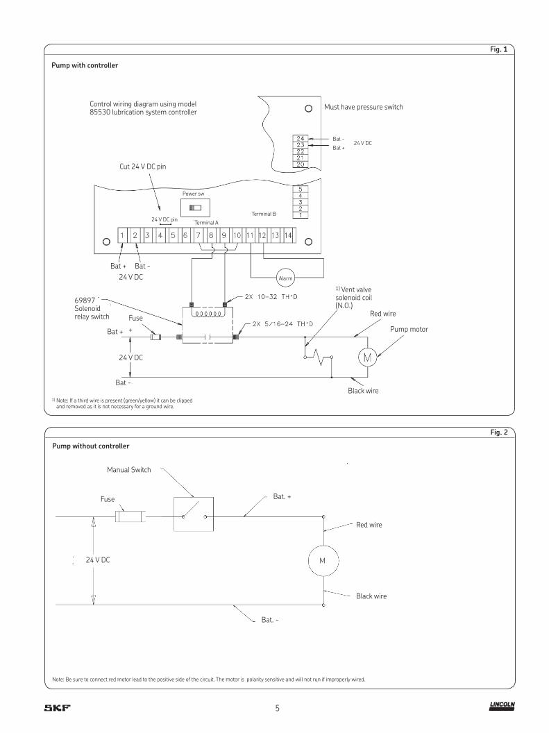
Pump without controller
Fig. 2
Fig. 1
Pump with controller
Control wiring diagram using model 85530 lubrication system controller
Must have pressure switch
1) Note: If a third wire is present (green/yellow) it can be clipped and removed as it is not necessary for a ground wire.
Cut 24 V DC pin
24 V DC pin
Power sw
Terminal B
Terminal A
69897Solenoid relay switch
Bat + Bat -24 V DC
Fuse
Bat +
Bat -
24 V DC
Alarm
1) Vent valve solenoid coil (N.O.)
Red wire
Pump motor
Black wire
Bat +
Bat -24 V DC
Note: Be sure to connect red motor lead to the positive side of the circuit. The motor is polarity sensitive and will not run if improperly wired.
Manual Switch
Fuse
24 V DC
Bat. +
Bat. -
Red wire
Black wire
M
5

Fig. 3
Models 85728 and 85729
"A"
BB
18.7474
A
A
20° 40°
Section B-B
15-1/8 [384 mm]
13-7/8 [352 mm] Bolt hole circle
1/2 [12.7 mm] Mounting holes 6 x 60 apart
Section A-A
20
2324
33
34
35
36
22
21
25
11
1
10
9
8
7
6
23
5
4
12
14
1516
173
18
19
26
2829
30
32
27
8
31
Dimensions
Model Dimension “A”
85728 29.2 in. (741 mm)85729 37.4 in. (950 mm)
6

Fig. 4
Model 85730
38.4975
BB
20.0507
A
A
45°
Section B-B
16-3/4 [425 mm]
15-1/2 [394 mm] Bolt hole circle
19/32 [15 mm] Mounting holes 4 x 90 apart
Section A-A
1 23
4 5
6
7
8
9
10
13
12
8
11
14
15
16
173
18
19
20
21
22
2324
25
26
27
2829
30
31
32
33
34
35
36
7

Fig. 8
Low level indicator
Fig. 7
Low level port
Fig. 6
Electric vent valve (27)
Fig. 5
Outlet check assembly (7)
/ in. NPTF41
37 38 39 40 41 42 43
44 45
46
FF
47
48
49
50
A A
51
52
53
54
55
5657
8

Fig. 9
Follower assembly (36)
C
C
SECTION C-C
58
59
60
61
61
62
63
64
65
59
66
67
66
68
69
Section C—C
9
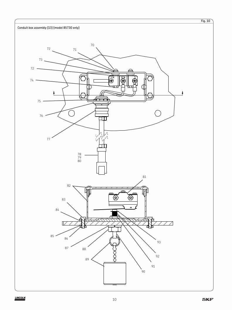
Fig. 10
Conduit box assembly (13) (model 85730 only)
N.C. N.O. C
707172
73
74
75
76
77
787980
72
82
81
83
84
8586
87 88
89
93
92
91
90
10

Service parts
Item Description Qty. Model 85728 Model 85729 Model 85730
1 Hose assembly 1 272711 272711 2727112 Hex head screw, 3/8-16 x 1 1/4 6 50015 50015 500153 Lockwasher, 3/8 8 66220 66220 66220
4 Male run tee 1 276370 276370 2763705 Adapter 1 12989 12989 129896 Adapter 1 12213 12213 12213
7 Outlet check assembly 1 81938 81938 819388 Elbow, 1/4 NPTF 2 277439 277439 2774399 Hose assembly 1 277441 277441 277441
10 Hose assembly 1 270726 270726 27072611 Reducer nipple 1 14727 14727 1472712 Vent fitting 1 249354 249354 249354
13 Conduit box assembly 1 NA NA 27275814 Fill tube 1 276853 276853 27685315 FlowMaster II electric pump 1 857373) 857373) 857373)
16 Eyebolt 2 276300 276300 27630017 Hex nut, 3/8-16 2 51005 51005 5100518 Drum cover 1 277996 277996 278007
19 Gasket 1 249355 249355 27194420 Pipe plug, 1 1/4 NPT 1 278009 278009 27800921 Reservoir assembly 1 277702 278008 278000
22 Pipe plug, 1 NPT 1 67346 67346 6734623 Hex head screw, 5/16-18 x 3/4 2 50016 50016 5001624 Lockwasher, 5/16 2 66246 66246 66246
25 Nipple 1 11197 11197 1119726 Elbow 1 10160 10160 1016027 Electric vent valve, 24 V DC 1 2774294) 2774294) 2774294)
28 Screw, 1/4-20x1 1/4 4 277728 277728 27772829 Lockwasher, 1/4 4 66186 66186 6618630 Pump gasket 1 277406 277406 277406
31 Safety unloader 1 2727222) 2727222 2727222
32 Vent fitting 1 272717 272717 27271733 Gasket 1 31010 31010 31010
34 Nut 1 12538 12538 1253835 Vent tube 1 67420 67420 6742036 Follower assembly 1 85689 85689 85720
37 Gasket 1 310291) 310291) 310291)
38 Outlet check bushing 1 902041)2) 902041)2) 902041)2)
39 Check disc assembly 1 802061)2) 802061)2) 802061)2)
40 Ball check seat 1 103131) 103131) 103131)
41 Gasket 1 310011) 310011) 310011)
42 Steel ball, 3/8 in. 1 660011)
43 Outlet connector 1 90860 90860 9086044 Solenoid coil, 24 V DC 1 277426 277426 27742645 Cartridge valve 1 276899 276899 276899
46 Valve body 1 276901 276901 27690147 Hex head screw, #10-24 x 5/8 5 50088 50088 5008848 Lockwasher, #10 5 68991 68991 68991
1) Suggested service replacement components.2) Sold as an assembly. Individual parts not available.3) See owner’s manual page C8-352 series for pump details.4) † Service page C8, section 328 series for service and troubleshooting.
11

Service parts (continued)
Item Description Qty. Model 85728 Model 85729 Model 85730
49 Cover, low level port 1 277681 277681 27768150 Gasket, low level port 1 274540 274540 27454051 Indicator bracket 1 361020 361020 361020
52 Retaining ring 1 688881) 688881) 688881)
53 Cable assembly 1 276852 277421 27801854 O-ring 1 2495321) 2495321) 2495321)
55 Indicator nut 1 16352 16352 1635256 Washer 1 48548 48548 4854857 Indicator plug 1 249357 249357 249357
58 Cover 1 276892 276892 27689259 Socket head screw, #10-24 x 1/2 8 50762 50762 5076260 Follower foam 1 276894 276894 278006
61 Locknut, 1/4-20 8 51304 51304 5130462 Weighted follower plate 1 276890 276890 27689063 O-ring (nitrile) 1 270720 270720 270720
64 Wiper cover 1 274318 274318 27431865 Wiper (fluorocarbon) 1 274321 274321 27432166 Spacer 12 241101 241101 241101
67 Hex head screw, 1/4-20 x 2 1/2 4 50062 50062 5006268 Hex head screw, 1/4-20 x 4 1/2 4 241102 241102 24110269 Follower plate 1 276888 276888 276888
70 Round head screw, #6-32 x 1 1/8 2 NA NA 5061871 Washer 2 NA NA 4835072 Gasket 4 NA NA 34748
73 Packing 2 NA NA 34413-1574 Hex nut, #6-32 2 NA NA 5108075 Conduit lock nut 1 NA NA 68020
76 Sealing o-ring 1 NA NA 27191177 Cord connector 1 NA NA 27165678 Deutsch plug, 2-way 1 NA NA 271651
79 Contact pin 2 NA NA 27137880 Wedge lock 1 NA NA 27165881 Switch 1 NA NA 68758
82 Conduit box 1 NA NA 27278983 Screw, #10-24 x 5/8 4 NA NA 5008884 Gasket 1 NA NA 271657
85 Lockwasher, #10 4 NA NA 6899186 Hex Nut, #10-24 4 NA NA 5110087 Lockwasher, 1/2 1 NA NA 69181
88 Hex jam nut, 1/2-20 1 NA NA 5103989 Weight assembly 1 NA NA 27165290 Rod 1 NA NA 14259
91 Stud 1 NA NA 27165492 Spring 1 NA NA 5530293 E-ring 1 NA NA 66765
1) Suggested service replacement components.2) Sold as an assembly. Individual parts not available.3) See owner’s manual page C8-352 series for pump details.
12

Troubleshooting
Condition Possible cause Corrective action
Pump does not operate. No electric power to pump. Turn on or connect electric supply to pump.• Motor Relay Failure Replace Relay• Motor Overheated Turn power off for 10 minutes and restart.• Motor tripped out on locked rotor protection Remove high pressure or repair cause of locked
pump.• Broken gearset or shaft. Repair gearbox• Blown Fuse Replace fuse, check for cause of overload.
Pump motor polarity is reversed. Check to see if red motor lead is wired to the positive side of the circuit.
Pump runs excessively. Pump tube malfunction. Refer to pump service page.
Outlet check damage or contamination. Repair check or remove contamination.
Vent valve damage or contamination. Repair vent valve or remove contamination.
System component leaking. Repair leaks.
Injector bypassing. Repair injectors.
Pump speeds up or runs erratically. Low level of grease or reservoir is empty. Refill reservoir.
Follower plate is stuck and separated from grease. Check follower plate and container for damage.
Pump piston or checks are worn. Refer to pump service sheet.
Pump runs, but output is low. Motor speed control set too low. Turn screw to speed up motor. See pump service page.
Faulty inlet or discharge check valve in pump. Replace faulty components. See pump service page.
Lubricant leaking from safety unloader valve. Pressure of system set too high. Adjust pressure switch setting.
Safety unloader damaged or contaminated. Replace safety unloader.
13

14
Lincoln industrial standard warrantyStandard limited warrantyLincoln warrants the equipment manufac-tured and supplied by Lincoln to be free from defects in material and workmanship for a period of one (1) year following the date of purchase, excluding there from any special, extended, or limited warranty pub-lished by Lincoln. If equipment is deter-mined to be defective during this warranty period, it will be repaired or replaced, within Lincoln’s sole discretion, without charge.
This warranty is conditioned upon the determination of a Lincoln authorized rep-resentative that the equipment is defective. To obtain repair or replacement, you must ship the equipment, transportation charges prepaid, with proof of purchase to a Lincoln Authorized Warranty and Service Center within the warranty period.
This warranty is extended to the original retail purchaser only. This warranty does not apply to equipment damaged from accident, overload, abuse, misuse, negligence, faulty installation or abrasive or corrosive material, equipment that has been altered, or equip-ment repaired by anyone not authorized by Lincoln. This warranty applies only to equip-ment installed, operated and maintained in strict accordance with the written specifica-tions and recommendations provided by Lincoln or its authorized field personnel.
This warranty is exclusive and is in lieu of any other warranties, express or implied, including, but not limited to, the warranty of merchantability or warranty of fitness for a particular purpose. War-ranty on items sold by Lincoln, but not manufactured by Lincoln are subject to the warranty consideration, if any, of their manufacturer (such as hoses, electric and electric motors, electrical controllers, etc.) Assistance in making such warranty claims can be offered as required.
In no event shall Lincoln be liable for inci-dental or consequential damages. Lincoln’s liability for any claim for loss or damages arising out of the sale, resale or use of any Lincoln equipment shall in no event exceed the purchase price. Some jurisdictions do not allow the exclusion or limitation of inci-dental or consequential damages, therefore the above limitation or exclusion may not apply to you.
This warranty gives you specific legal rights. You may also have other rights that vary by jurisdiction.
Customers not located in the Western Hemisphere or East Asia: Please contact Lincoln GmbH and Co. Kg, Walldorf, Germany, for your warranty rights.
Special limited warranties
Special limited 2 year warranty sl-v series, single injectors-85772, 85782, replacement injectors-85771, 85781 nd FlowMaster IILincoln warrants the SL-V Injector series and FlowMaster II "pump only" models to be free from defects in material and workman-ship for two (2) years following the date of purchase. If an injector model (single or re-placement) or FlowMaster II pump is deter-mined to be defective by Lincoln, in its sole discretion, during this warranty period, it will be repaired or replaced, at Lincoln’s discre-tion, without charge.
Special limited 5 year warranty series 20, 25, 40 bare pumps, pmv bare pumps, heavy duty and 94000 series bare reelsLincoln warrants series 20, 25, 40 bare pumps, PMV bare pumps, heavy duty (82206), mini bench (81133, 81323), and all 94000 LFR series (single arm and dual arm) bare reels to be free from defects in material and workmanship for five (5) years following the date of purchase. If equipment is determined by Lincoln, in its sole discre-tion, to be defective during the first year of the warranty period, it will be repaired or replaced at Lincoln’s discretion, without charge. In years two (2) and three (3), the warranty on this equipment is limited to re-pair with Lincoln paying parts and labor only. In years four (4) and five (5), the war-ranty on this equipment is limited to repair with Lincoln paying for parts only.
Special limited 5 year warranty- limited oil meters, limited fluid control valves, aod (air-operated diaphragm pumps)Lincoln warrants the 712 series control valves, 912 series lube meters, electronic lube meters (980. 981, 982 series), our nniversal inline digital meters (812/813 se-ries), and our AOD pump offering to be free from defects in material and workmanship for five (5) years following the date of pur-chase. If either is determined to be defective by Lincoln, in its sole discretion, during the warranty period, they will be repaired or re-placed, at Lincoln’s discretion, without charge.
Special DEF (diesel exhaust fluid) limited warrantyDEF products are warranted to be free from defects in material and workmanship for a period of one (1) year following the date of purchase. The following exceptions to the standard warranty period are in effect:
• 85700-30/85700-50 DEF hose reels (bare reel only),277251/277252 AC DEF pumps, and 277256 and 277257 DEF meters are warranted for two (2) years from date of purchase.
• 85623 DEF AOD (air operated diaphragm) pumps are covered under the standard five (5) year AOD pump warranty.
If either is determined to be defective by Lincoln, in its sole discretion, during the warranty period, they will be repaired or re-placed, at Lincoln’s discretion, without charge.
Lincoln Industrial contact informationTo find Lincoln Industrial’s nearest service center call one of the following number;customer service 314-679-4200or you may also use our websitewww.lincolnindustrial.com

This page left intentionally blank.
15

® SKF is a registered trademark of the SKF Group.
® Centro-Matic and Lincoln are registered trademarks of Lincoln Industrial Corp.TM FlowMaster II is a registered trademark of Lincoln Industrial Corp.
© SKF Group 2012The contents of this publication are the copyright of the publisher and may not be reproduced (even extracts) unless prior written permis-sion is granted. Every care has been taken to ensure the accuracy of the information contained in this publication but no liability can be accepted for any loss or damage whether direct, indirect or consequential arising out of the use of the information contained herein.
SKF PUB LS/I1 13133 EN.US · May 2013 · Form 404443
Printed in USA on environmentally friendly paper.
Bearings and unitsSeals Lubrication
systems
Mechatronics Services
The Power of Knowledge Engineering
Drawing on five areas of competence and application-specific expertise amassed over more than 100 years, SKF brings innovative solutions to OEMs and production facilities in every major industry world-wide. These five competence areas include bearings and units, seals, lubrication systems, mechatronics (combining mechanics and electronics into intelligent systems), and a wide range of services, from 3-D computer modelling to advanced condition monitoring and reliability and asset management systems. A global presence provides SKF customers uniform quality standards and worldwide product availability.
lincolnindustrial.com skf.com/lubrication