flowiz™ - isoilarchivio.isoil.eu/ml255_en_ds035.pdf · • one photovoltaic panel that converts...
TRANSCRIPT

FLOWIZ™
( M L 2 5 5 )
TH
E M
OS
T A
CC
UR
AT
E B
AT
TE
RY
PO
WE
RE
D S
YS
TE
M
Warranty conditions are available on this website: www.isomag.eu only in English version
E lec t romagnet ic c onvert er p owered by bat t er ies and un iversa l p ower supp ly . Opt iona l bu i l t in m odu les f or GPRS t ransm iss ion and pressure m easurem ent .
ML 255
The manufacturer guarantees only English text Page 2 of 18 ML255_EN_DS035REV02_IS available on our web site: www.isomag.eu
I N D E X
TECHNICAL DATA ................................................................................................................................ 3
OVERALL FEATURES ............................................................................................................................. 3
STANDARD FEATURES .......................................................................................................................... 3
OPTIONAL FEATURES ........................................................................................................................... 4
ACCURACY ........................................................................................................................................... 4
OVERALL DIMENSIONS......................................................................................................................... 5
VISUALIZATION PAGES ........................................................................................................................ 6
PCB LAYOUT ........................................................................................................................................ 7
POWER SUPPLY ................................................................................................................................... 8
ELECTRICAL CONNECTIONS ................................................................................................................ 10
DIGITAL INPUT / OUTPUT ................................................................................................................... 11
FUNCTION’S LIST ................................................................................................................................ 12
MEASURE / SAMPLE FREQUENCY ......................................................................................................... 14
BATTERIES CONSUMPTION ................................................................................................................. 15
BATTERIES LIFE .................................................................................................................................. 16
ACCURACY TABLE ............................................................................................................................... 17
HOW TO ORDER ................................................................................................................................. 18

ML 255
The manufacturer guarantees only English text Page 3 of 18 ML255_EN_DS035REV02_IS available on our web site: www.isomag.eu
T E C H N I C A L D A T A
OVERALL FEATURES
Suitable For ISOMAG sensors
Minimum conductivity 5 S/cm
Version Compact Separate
Power consumption 0.08W With Batteries; Average 0.2W/Max 3 W With
Universal Power
Altitude -200 m up to 2000 m
Ambient Temperature -20… +60°C / -4… +140 °F
Humidity Range 0÷100% (IP 67)
Accuracy See Table
STANDARD FEATURES
Housing materials Painted Aluminium die casting
Protection Rate IP 67
Power Supply Mixed System Batteries and main Power Supply; n° 1 Size
D Not Rechargeable Lithium Battery +Universal Power Supply :12-60V / 100÷240V~
Data Logger MicroSD Memory Card 2 GBytes
Data storage F-Ram
Protocols ETP
Galvanic Isolation All the inputs/outputs are galvanically isolated from
power supply up to 500 V
Programming Plug In Protected plug in for the connection to PC (IF2X interface)
Bi-Directional Yes
Dual Range Yes
Diagnostic Funct. Yes
Empty Pipe Detect. Yes
CE Certification Yes
ML 255
The manufacturer guarantees only English text Page 4 of 18 ML255_EN_DS035REV02_IS available on our web site: www.isomag.eu
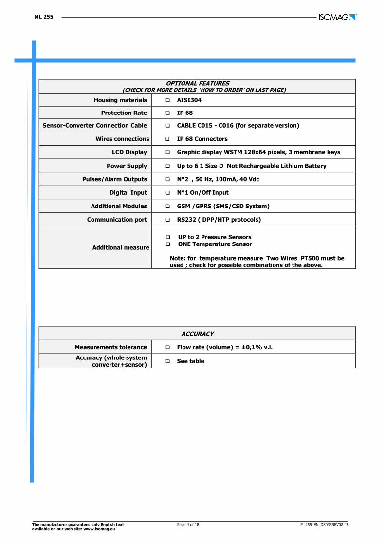
OPTIONAL FEATURES (CHECK FOR MORE DETAILS ‘HOW TO ORDER’ ON LAST PAGE)
Housing materials AISI304
Protection Rate IP 68
Sensor-Converter Connection Cable CABLE C015 - C016 (for separate version)
Wires connections IP 68 Connectors
LCD Display Graphic display WSTM 128x64 pixels, 3 membrane keys
Power Supply Up to 6 1 Size D Not Rechargeable Lithium Battery
Pulses/Alarm Outputs N°2 , 50 Hz, 100mA, 40 Vdc
Digital Input N°1 On/Off Input
Additional Modules GSM /GPRS (SMS/CSD System)
Communication port RS232 ( DPP/HTP protocols)
Additional measure
UP to 2 Pressure Sensors ONE Temperature Sensor
Note: for temperature measure Two Wires PT500 must be used ; check for possible combinations of the above.
ACCURACY
Measurements tolerance Flow rate (volume) = ±0,1% v.l.
Accuracy (whole system converter+sensor)
See table

ML 255
The manufacturer guarantees only English text Page 5 of 18 ML255_EN_DS035REV02_IS available on our web site: www.isomag.eu
ENTER
ESC
175
147
146
139
139
25
230
171
209
211
152
287
208
CABLEGLAND PG11
PRESSURE PROBE
PG11 CAP
QUICK CONNECTOR
SEPARATE VERSIONaluminium housing weight: 3Kg;
stainless steel housing weight: 3.5kg
COMPACT VERSIONaluminium housing weight: 2.5Kg;stainless steel housing weight: 3kg
LAYOUT AND QUANTITY IN ACCORDINGTO ORDER CODE
Weights refer to the converter without battery (each battery weights 0.1kg),which can be provided with 6 batteries maximum and without display, blind configuration.
ENTER
ESC
38
3 METERS
MAGNETIC AND ADHESIVE BASE
80
VERSION WITH 3 METERS CABLE ANTENNA
O V E R A L L D I M E N S I O N S

ML 255
The manufacturer guarantees only English text Page 6 of 18 ML255_EN_DS035REV02_IS available on our web site: www.isomag.eu
FLOWRATE VALUE / % FULL SCALEGRAPHIC OF FLOW RATE-TIME
FLOWRATE VALUE / TOTAL ANDPARTIAL TOTALIZER OF DIRECT
FLOWRATE
FLOWRATE VALUE / TOTAL ANDPARTIAL TOTALIZER OF INVERSE
FLOWRATE
FLOWRATE VALUE / TOTAL ANDPARTIAL NET TOTALIZER
FLOWRATE VALUE /% FULL SCALE BARGRAPH
PRESSURE VALUES ( 1&2)DIFFERENTIAL PRESSURE
BATTERY STATUS
BOARD TEMPERATURE ANTENNA SIGNAL / ALARMS
V I S U A L I Z A T I O N P A G E S
Different visualization possibilities by simply pressing a key
ML 255
The manufacturer guarantees only English text Page 7 of 18 ML255_EN_DS035REV02_IS available on our web site: www.isomag.eu
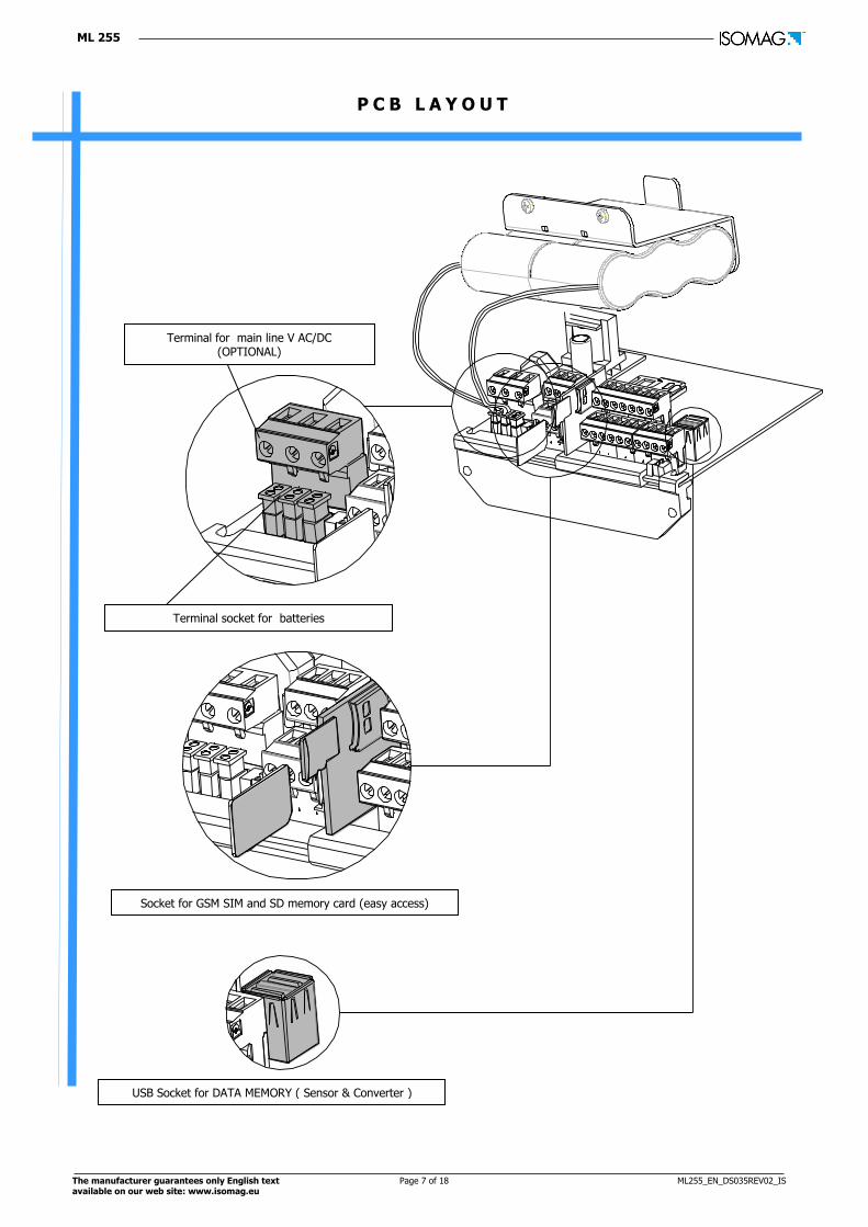
P C B L A Y O U T
Socket for GSM SIM and SD memory card (easy access)
USB Socket for DATA MEMORY ( Sensor & Converter )
Terminal for main line V AC/DC (OPTIONAL)
Terminal socket for batteries

ML 255
The manufacturer guarantees only English text Page 8 of 18 ML255_EN_DS035REV02_IS available on our web site: www.isomag.eu
B1B2B3
OFF
ON
GPRS BATTERY
CONVERTER BATTERY
CONVERTER BATTERY
B1 B2 B3
P O W E R S U P P L Y
BY MAIN VOLTAGE
Auto detection of the power source: when main power supply is ON, batteries are excluded and the system always works at the maximum sampling rate (continuous sampling)
BY BATTERIES
Note : Lithium batteries are subject to special transportation regulations according to “Regulation of Dangeroug Goods, UN3090 and UN 3091”. Special documentation is required to observe there regulations.
ML 255
The manufacturer guarantees only English text Page 9 of 18 ML255_EN_DS035REV02_IS available on our web site: www.isomag.eu
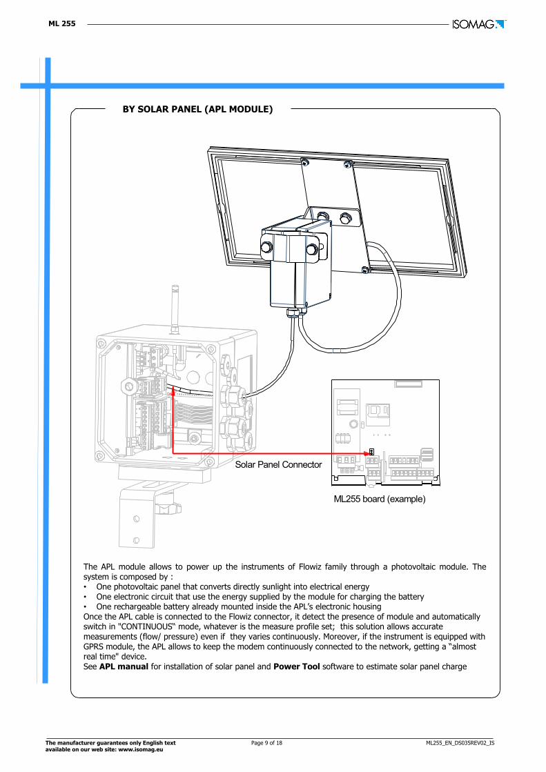
Solar Panel Connector
ML255 board (example)
BY SOLAR PANEL (APL MODULE)
The APL module allows to power up the instruments of Flowiz family through a photovoltaic module. The system is composed by : • One photovoltaic panel that converts directly sunlight into electrical energy • One electronic circuit that use the energy supplied by the module for charging the battery • One rechargeable battery already mounted inside the APL’s electronic housing Once the APL cable is connected to the Flowiz connector, it detect the presence of module and automatically switch in "CONTINUOUS“ mode, whatever is the measure profile set; this solution allows accurate measurements (flow/ pressure) even if they varies continuously. Moreover, if the instrument is equipped with GPRS module, the APL allows to keep the modem continuously connected to the network, getting a “almost real time" device. See APL manual for installation of solar panel and Power Tool software to estimate solar panel charge

ML 255
The manufacturer guarantees only English text Page 10 of 18 ML255_EN_DS035REV02_IS available on our web site: www.isomag.eu
1 2 3 4 5 6 7 8 9 10
11 12 13 14 15 16 17
E1 E2 C SH + -ELECTRODES INPUT
EC2C1SC
B2B1SCOUT1 OUT2
COMOUT1 OUT2
COLLECTORSCOILS
SGRX
RS232
TX
SC
Pre
ss.
1 (
+)
18 19 20
23 22 21
PRESSUREPower +
PRESSUREPower -
PRESSU
RE
SENSO
R 1
PRESSU
RE
SENSO
R 2
Pre
ss.
1 (
-)
Pre
ss.
2 (
-)
Pre
ss.
2 (
+)
Temperature probe ( INSTEAD OF PRESSURE 2)
PR
ES
SU
RE
1 P
RO
BE
CA
BLE SENSOR'S CABLES
PULSES
ALARM
PR
ES
SU
RE
2 P
RO
BE
CA
BLE
PRV VALVE
OUTPUTS CABLE
E L E C T R I C A L C O N N E C T I O N S
TERMINAL BLOCK: COMPACT/SEPARATE VERSION
IP 68 VERSION : CONNECTION WITH IP 68 CONNECTORS

ML 255
The manufacturer guarantees only English text Page 11 of 18 ML255_EN_DS035REV02_IS available on our web site: www.isomag.eu
ON/OFF INPUT
3/40 Vdc (ON)
0/1,5 Vdc (OFF)
5 K
Terminal 5 (+)
Terminal 6 (-)
Terminal 15 / 16
Terminal 17
(Out1) (Out2)
COMOUT 1-2
ON/OFF OUTPUT
D I G I T A L I N P U T / O U T P U T
ML 255
The manufacturer guarantees only English text Page 12 of 18 ML255_EN_DS035REV02_IS available on our web site: www.isomag.eu
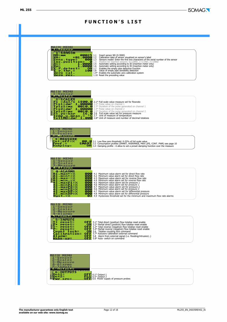
2.1* Full scale value measure set for flowrate2.2* Pulse value on channel 12.3* Duration of the pulse generated on channel 1
2.5* Duration of the pulse generated on channel 22.6 Full scale value set for pressure measure
2.8* Unit of measure and number of decimal totalizes2.7 Unit of measure of temperature
2.4* Pulse value on channel 2
4.1 Maximum value alarm set for direct flow rate4.2 Minimum value alarm set for direct flow rate4.3 Maximum value alarm set for reverse flow rate
4.5 Maximum value alarm set for pressure 14.6 Minimum value alarm set for pressure 1
4.4 Minimum value alarm set for reverse flow rate
4.7 Maximum value alarm set for pressure 24.6 Minimum value alarm set for pressure 24.7 Maximum value alarm set for differential pressure4.8 Minimum value alarm set for differential pressure4.9 Hysteresis threshold set for the minimum and maximum flow rate alarms
5.1* Total direct (positive) flow totalise reset enable5.2* Partial direct (positive) flow totalise reset enable5.3* Total reverse (negative) flow totalise reset enable
5.6 Totalise counting lock command5.7* Autozero calibration external command
5.4* Partial reverse (negative) flow totalise reset enable
5.8 Alarm from external signal (i.e. flooding/intrusion/..)5.8* Auto- switch on command
6.1* Output 1
6.6 Power supply of pressure probes6.5* Output 2
1.1 Insert sensor ND (0-3000)1.2 Calibration data of sensor visualized on sensor's label1.3 Sensors model: Enter the first two characters of the serial number of the sensor1.4 Position for insertion sensors: 0=1/8ND, 1=1/2ND, 2=7/8ND1.5 Automatic setting according to ID (insertion meter only)1.6 Automatic setting according to ID (insertion meter only)1.7 Enables the empty pipe detection function1.8 Value of empty pipe sensibility detection1.9* Enables the automatic zero calibration system1.10 Reset the preceding value
3.1 Low flow zero threshold: 0-25% of full scale value3.2 Consumption profiles (SMART, AVERANGE, MAX LIFE, CONT. PWR) see page 103.4 Damping profile : it allow to set a preset damping function over the measure
F U N C T I O N ’ S L I S T

ML 255
The manufacturer guarantees only English text Page 13 of 18 ML255_EN_DS035REV02_IS available on our web site: www.isomag.eu
8.1 Choice of the language: EN= English, IT=Italian, FR= French, SP= Spanish8.2 Time for switch off display (shown with function 3.7 enabled)8.3 Visualization of "Quick start menu"
8.5* Total direct (positive) flow totalizer reset from keyboard8.6* Partial direct (positive) flow totalizer reset from keyboard
8.4 lock of DISPLAY in ONE SPECIFIC visualization page
8.7* Total reverse (negative) flow totalizer reset enable from keyboard8.8* Partial reverse (negative) flow totalizer reset enable from keyboard
* (Communication function group only) = see wireless specific manual supplied for more details
7.1 Choice of the IF2 communication protocol
7.5 Minimum antenna signal strength to send e-mail*7.6 Choice of how to send data logger*
7.8 Interval of data logger sending if 7.7 is set on "PERIODIC"*7.9 Interval of sending DATA LOGGER*
7.7 Choice of when send data logger*
7.10 Enables send Process data*7.11 Enables send Alarm*
7.19 Send EVENTS, instant command*
7.17 Roaming enable*7.18 Send Data Logger, instant command*
7.20 Send configuration through e-mail immediately*7.21 Clock synchronization, immediately, with a specified server via the HTTP protocol*
7.23 Check INCOMING SMS, instant command*
7.12 Enables check INCOMING SMS*
7.22 Check INCOMING E-MAIL, instant command*
7.13 Enables check INCOMING E-MAIL*7.14 Enables clock synchronization with a specified server via the HTTP protocol*7.15 Enables send EVENTS*
7.2 Choice of the RS232 communication protocol*7.3 Address RS232 port*7.4 RS232 port speed*
7.16 Enable send sensor test in automatic mode*
7.24 Send sensor test in manual mode*
9.1 Date and time set9.2 Set of Time Zone (Against GMT -12 to +12 hours)9.3* Automatic data logger enable
9.5 Choice of single (off) or double (on) logging interval9.6 Interval time 1 for the data logging function
9.4 Data formatted like ML250 (see ML250 manual)
9.7 Interval time 2 for the data logging function
9.11 Enables the logging of direct total totalizer9.12 Enables the logging of direct partial totalizer9.13 Enables the logging of reverse total totalizer9.14 Enables the logging of reverse partial totalizer9.15 Enables the logging of net total totalizer9.16 Enables the logging of net partial totalizer9.17 Enables the logging of flow rate 9.18 Enables the logging of pressure 19.19 Enables the logging of pressure 29.20 Enables the logging of differential pressure9.21 Enables the logging of temperature9.22 Enables the logging of statistical data (ant. signal, batt. status, board temp.,..)9.23 Enables the sending of measure units (technical units) 9.24 Enables the sending of measure units (%)9.25 Symbol used as separator on CSV files
9.9 Interval 2, start logging time9.10 Interval 2, stop logging time
9.8 Interval period 2 for the data logging function
10.1 Perfom a sensor test (SENSOR MUST BE CONNECTED)10.2* Converter auto-test
10.4* Stand-by function10.5 Test of GPRS connections
10.3* Flow rate simulation enabling
10.6 SD card status/info10.7 Firmware revision/version
11.1 Level 2 access code enter11.2 Load factory data pre-set11.3 Enable the B2 batteries SLOT (1/2/3 according to the number of batteries pack)*11.4 Ks Coefficient
Note : all references to page number are linked to the operating manual .

ML 255
The manufacturer guarantees only English text Page 14 of 18 ML255_EN_DS035REV02_IS available on our web site: www.isomag.eu
FLOWRATEPROFILE
CONTINUOSSAMPLING
SMARTSAMPLING
Max S.R.
5 Sec.
AVERAGESAMPLING
3 Sec.
Max S.R.
3 Sec. 3 Sec.
VARIABLE S.R.VARIABLE S.R.
Measures at maximum sample rate
Automatic Sample rate according to flow profile
Sample rate at 3 seconds
TIME
MAX BATTERYLIFE SAMPLING
15 Sec. 15 Sec. 15 Sec.
S.R.=SAMPLE RATE
Sample rate at 15 seconds
VARIABLE CONSTANT VARIABLE
Max S.R.
M E A S U R E / S A M P L E F R E Q U E N C Y
ML 255 can be programmed to measure in four different modes:
ML 255
The manufacturer guarantees only English text Page 15 of 18 ML255_EN_DS035REV02_IS available on our web site: www.isomag.eu
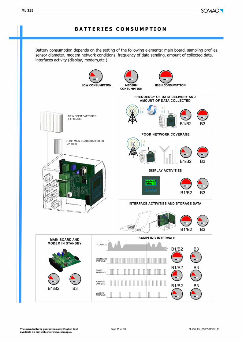
B A T T E R I E S C O N S U M P T I O N
Battery consumption depends on the setting of the following elements: main board, sampling profiles,
sensor diameter, modem network conditions, frequency of data sending, amount of collected data,
interfaces activity (display, modem,etc.).
LOW CONSUMPTION
MEDIUM
CONSUMPTION
HIGH CONSUMPTION
B1/B2: MAIN BOARD BATTERIES (UP TO 3)
B3: MODEM BATTERIES ( 3 PIECES)
MAIN BOARD ANDMODEM IN STANDBY FLOWRATE
CONTINUOSSAMPLING
SMARTSAMPLING
AVERAGESAMPLING
MAX LIFESAMPLING
SAMPLING INTERVALS
INTERFACE ACTIVITIES AND STORAGE DATA
DISPLAY ACTIVITIES
POOR NETWORK COVERAGE
B1/B2
FREQUENCY OF DATA DELIVERY ANDAMOUNT OF DATA COLLECTED
B3
B1/B2 B3
B1/B2 B3
B1/B2 B3
B1/B2 B3
B1/B2 B3
B1/B2 B3
B1/B2 B3

ML 255
The manufacturer guarantees only English text Page 16 of 18 ML255_EN_DS035REV02_IS available on our web site: www.isomag.eu
Power tool is a software which allows to evaluate the converter battery life. The estimation is done with an easy guided procedure
B A T T E R I E S L I F E
Low power consumption: a number of design strategies have been employed to achieve exceptionally low power consumption. However, the length of time between battery changes depends on a number of data transmission per day, GPRS signal strength and the frequency of sampling and logging.
NOTE: the Customer is solely responsible for ensuring that there is sufficient GPRS/GSM mobile network coverage for each device, and that neither the reseller nor ISOIL shall have any liability in the event of a reduction or cessation of such coverage.
POWER TOOL SOFTWARE
ML 255
The manufacturer guarantees only English text Page 17 of 18 ML255_EN_DS035REV02_IS available on our web site: www.isomag.eu
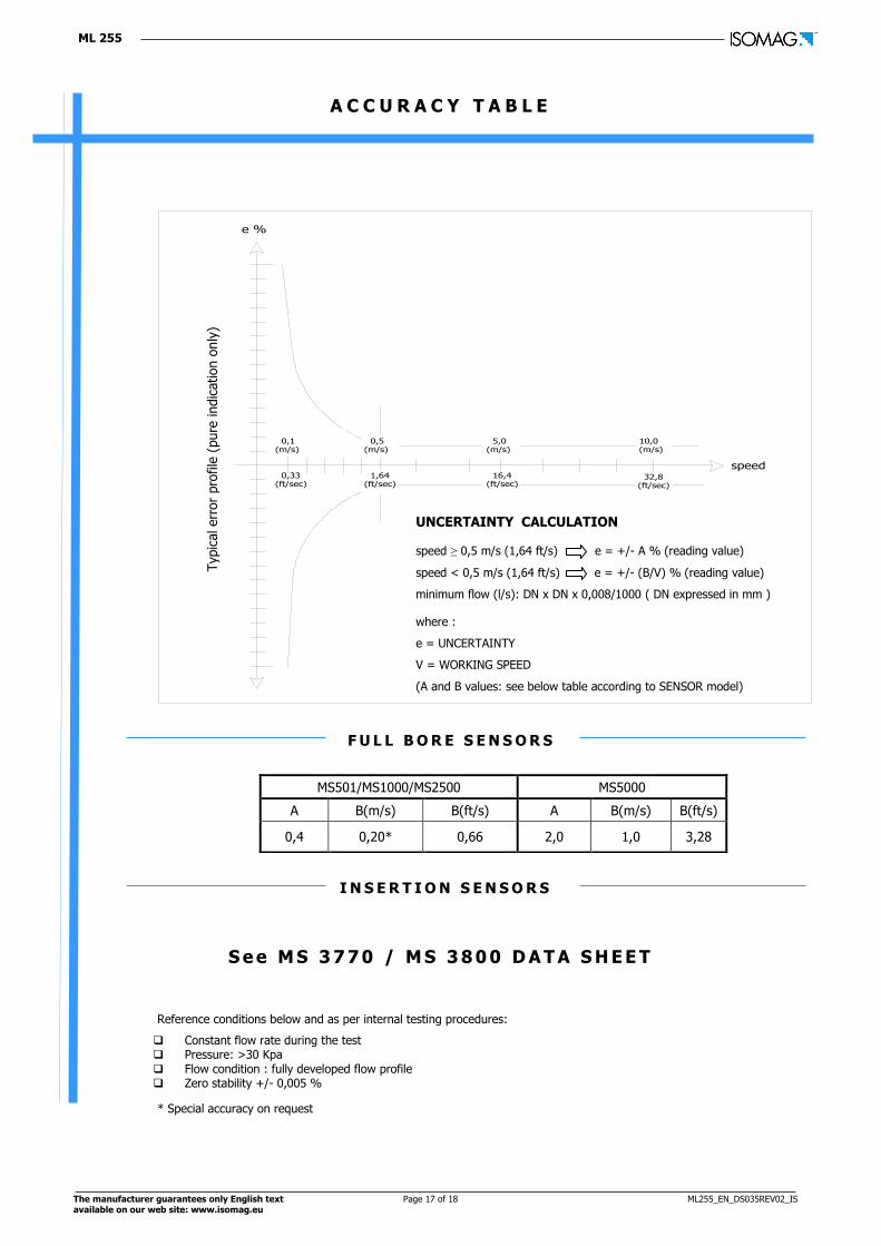
A C C U R A C Y T A B L E
S e e M S 3 7 7 0 / M S 3 8 0 0 D A T A S H E E T
Reference conditions below and as per internal testing procedures:
* Special accuracy on request
MS501/MS1000/MS2500 MS5000
A B(m/s) B(ft/s) A B(m/s) B(ft/s)
0,4 0,20* 0,66 2,0 1,0 3,28
F U L L B O R E S E N S O R S
Constant flow rate during the test Pressure: >30 Kpa Flow condition : fully developed flow profile Zero stability +/- 0,005 %
Typic
al err
or
pro
file
(pure
indic
ation o
nly
)
e %
speed
0,1 (m/s)
0,33(ft/sec)
0,5 (m/s)
1,64(ft/sec)
5,0 (m/s)
16,4(ft/sec)
10,0 (m/s)
32,8(ft/sec)
UNCERTAINTY CALCULATION speed ≥ 0,5 m/s (1,64 ft/s) e = +/- A % (reading value)
speed < 0,5 m/s (1,64 ft/s) e = +/- (B/V) % (reading value)
minimum flow (l/s): DN x DN x 0,008/1000 ( DN expressed in mm )
where :
e = UNCERTAINTY
V = WORKING SPEED
(A and B values: see below table according to SENSOR model)
I N S E R T I O N S E N S O R S
ML 255
Production/stock 35044 Montagnana – PD
Via Piemonte , n° 2
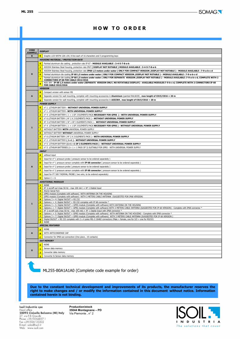
H O W T O O R D E R
ML255-B0A1A1A0 (Complete code example for order)
CODE EXAMPLE
DISPLAY
B B Graphic LCD WSTN 128 x 64, 8 line each of 16 characters and 3 programming keys
HOUSING MATERIAL / PROTECTION RATE
0
0 Painted aluminum die casting , protection rate IP 67 - MODULE AVAILABLE : 3-4-5-7-8-a-b
1 AISI304 Stainless Steel housing, protection rate IP67 ( DISPLAY NOT ROTABLE ) MODULE AVAILABLE : 3-4-5-7-8-a-b
5 AISI304 Stainless Steel housing, protection rate IP68 1,5 meters under water ( ONLY FOR COMPACT VERSION ,DISPLAY NOT ROTABLE ) - MODULE AVAILABLE : 7-9-a-b-c-d
6 Painted aluminium die casting IP 68 1,5 meters under water ( ONLY FOR COMPACT VERSION ,DISPLAY NOT ROTABLE ) - MODULE AVAILABLE : 7-9-a-b-c-d
7 Painted aluminium die casting IP 68 1,5 meters under water ( ONLY FOR SEPARATE VERSION ,DISPLAY NOT ROTABLE ) - MODULE AVAILABLE :7-9-a-b-c-d, COMPLETE WITH 2 CONNECTORS IP 68 FOR CABLE C015/C016
8 AISI 304 - IP 68 1,5 meters under water (SEPARATE VERSION ONLY, NO ROTATABLE DISPLAY) - AVAILABLE MODULES:7-9-b-c-d, COMPLETE WITH 2 CONNECTORS IP 68 FOR CABLE C015/C016
VERSION
A
A Compact version with sensor MS
B Separate version for wall mounting, complete with mounting accessories in Aluminium (painted RAL6028) , max lenght of C015/C016 = 20 m
D Separate version for wall mounting, complete with mounting accessories in AISI304 , max lenght of C015/C016 = 20 m
POWER SUPPLY
1
0 n° 1 LITHIUM BATTERY - WITHOUT UNIVERSAL POWER SUPPLY
1 n° 1 LITHIUM BATTERY- WITH UNIVERSAL POWER SUPPLY
2 n° 4 LITHIUM BATTERY ( 1 + 1 OF 3 ELEMENTS PACK NECESSARY FOR GPRS ) - WITH UNIVERSAL POWER SUPPLY
4 n° 6 LITHIUM BATTERY ( N° 2 X 3 ELEMENTS PACK ) - WITHOUT UNIVERSAL POWER SUPPLY
5 N° 3 LITHIUM BATTERY ( N° 1 OF 3 ELEMENTS PACK ) - WITHOUT UNIVERSAL POWER SUPPLY
6 n° 4 LITHIUM BATTERY ( 1 + 1 OF 3 ELEMENTS PACK NECESSARY FOR GPRS ) - WITHOUT UNIVERSAL POWER SUPPLY
7 WITHOUT BATTERY WITH UNIVERSAL POWER SUPPLY
8 WITHOUT BATTERY WITHOUT UNIVERSAL POWER SUPPLY
9 n° 6 LITHIUM BATTERY ( N° 2 X 3 ELEMENTS PACK ) - WITH UNIVERSAL POWER SUPPLY
a n° 2 LITHIUM BATTERY ( 1+1 ) - WITHOUT UNIVERSAL POWER SUPPLY
b n° 5 LITHIUM BATTERY (1+1 +1 OF 3 ELEMENTS PACK ) - WITHOUT UNIVERSAL POWER SUPPLY
c n° 5 LITHIUM BATTERIES (1+ 1 + 1 PACK OF 3) SUITABLE FOR GPRS - WITH UNIVERSAL POWER SUPPLY
INPUT
A
A without input
C Input for n° 1 pressure probe ( pressure sensor to be ordered separately )
D Input for n° 1 pressure sensor complete with IP 68 connector ( pressure sensor to be ordered separately )
E Input for n° 2 pressure probe ( pressure sensor to be ordered separately )
F Input for n° 2 pressure sensor complete with IP 68 connector ( pressure sensor to be ordered separately )
G Input for PT 500 THERMAL PROBE ( two wire, to be ordered separately)
H Option C + G
ADDITIONAL MODULES
1
1 NONE
3 N° 2 on/off out (max 50 Hz - max 100 mA ) + N° 1 Digital Input
4 RS232 Serial Port
5 GPRS module (Complete with software) WITH ANTENNA ON THE HOUSING
7 GPRS module (Complete with software) WITH 3 METERS CABLE ANTENNA (SUGGESTED FOR IP68 VERSION)
8 Options 3 + 4: Digital IN/OUT + RS 232
9 Options c + 4: Digital IN/OUT + RS 232 complete with IP 68 connector *
a Options 3 + 5: Digital IN/OUT + GPRS module (Complete with software) WITH ANTENNA ON THE HOUSING
b Options c + 7: Digital IN/OUT + GPRS module (Complete with software) WITH 3 METERS CABLE ANTENNA (SUGGESTED FOR IP 68 VERSION) - Complete with IP68 connector *
c N° 2 on/off outs (max 50 Hz - max 100 mA) + N° 1 Digital Input with IP68 connector *
e Options c + 5: Digital IN/OUT + GPRS module (Complete with software) WITH ANTENNA ON THE HOUSING - Complete with IP68 connector *
f Options 3 + 7: Digital IN/OUT + GPRS module (Complete with software) WITH 3 METERS CABLE ANTENNA (SUGGESTED FOR IP 68 VERSION )
g Digital IN/OUT + RS 232 complete with 2 x 4 poles MIL-C-26482 connectors (Male + female, one for I/O + one for RS232)
Z NONE
SPECIAL FEATURES
A
A NONE
B WITH ANTICONDENSE CAP
C Connector for IP68 out connection (One piece , 10 contacts)
DAT MEMORY
0
0 NONE
1 Sensor data memory
2 Converter data memory
3 Converter & Sensor data memory
Due to the constant technical development and improvements of its products, the manufacturer reserves the right to make changes and / or modify the information contained in this document without notice. Information contained herein is not binding.