flowcad an pspice model config note place titel here page 1 von 11 title: configuration of pspice...
TRANSCRIPT

Application Note Place Titel here Page 1 von 11
Title: Configuration of PSpice Model Libraries Product: OrCAD PSpice A/D, OrCAD PSpice AA
and Allegro AMS Simulator Summary: This application note describes how you
can find PSpice models, how you can use PSpice Model Editor to create a part symbol for Capture based on a PSpice model and how you can configure libraries.
Author/Date: Wei Ling / 24.8.2010 Update/Date: Pascal Willems / 3.10.2013
Table of Contents
1 Find PSpice Models ....................................................................................................... 2
2 Associate a model to a Part ............................................................................................ 2
3 Create a Part Symbol using PSpice Model Editor ........................................................... 3
3.1 With the Wizard ....................................................................................................... 4
3.2 Manually (Without Wizard) ...................................................................................... 6
3.3 Configure the Libraries ............................................................................................ 7
4 Bibliography ..................................................................................................................11

Application Note Place Titel here Page 2 von 11
1 Find PSpice Models
The most commonly used models are available in the PSpice model libraries shipped with your software. The model library names have a .lib extension. But some models you need can’t be found in these standard libraries. You may try with the following ways:
• Go to Cadence website http://www.cadence.com/products/orcad/Pages/downloads.aspx
• Search PSpice models in the internet e.g. www.google.com
• Ask the vendor for the possible PSpice models directly
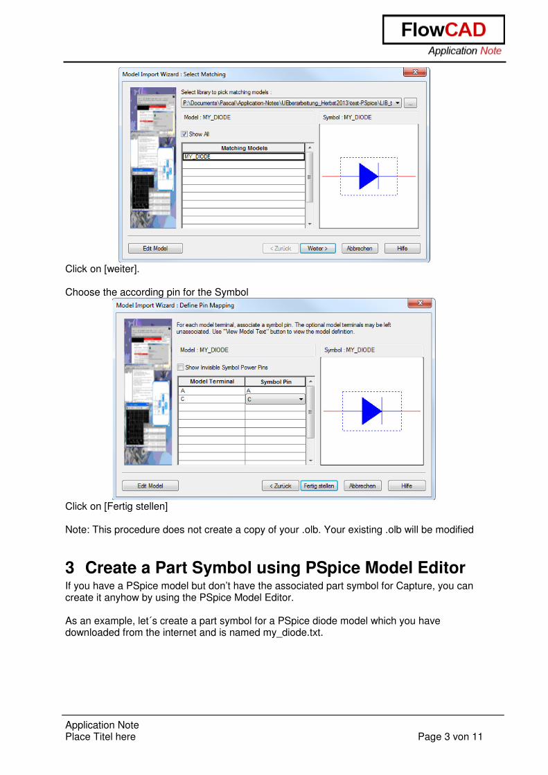
2 Associate a model to a Part Open the .olb in Capture Right-click on the Part you want to add a PSpice Model � Associate PSpice Model…
In the Window, which pops up, you can choose the .lib in which your model is.
Application Note Place Titel here Page 3 von 11
Click on [weiter]. Choose the according pin for the Symbol
Click on [Fertig stellen] Note: This procedure does not create a copy of your .olb. Your existing .olb will be modified
3 Create a Part Symbol using PSpice Model Editor If you have a PSpice model but don’t have the associated part symbol for Capture, you can create it anyhow by using the PSpice Model Editor. As an example, let´s create a part symbol for a PSpice diode model which you have downloaded from the internet and is named my_diode.txt.

Application Note Place Titel here Page 4 von 11
3.1 With the Wizard
3.1.1 Rename the File and open it in Model Editor
Rename the file from my_diode.txt to my_diode.lib, then save it.
Go into Windows Start Menu: Start���� All Programs���� Cadence ���� Release16.6 ���� PSpice Accessories���� Model Editor (the procedure which depends on the software installation may be different at your end)���� If the Select Design Entry Tool window comes up, check Capture ���� Done. In PSpice Model Editor window click File ���� Open… ���� Open the my_diode.lib file you just saved and renamed. You can see the model definition below
3.1.2 Create a Part Symbol for Capture
Select the my_diode in the Models List window.

Application Note Place Titel here Page 5 von 11
3.1.3 Open the Wizard
Select in the Menu. File���� Model Import Wizard [Capture]…���� The Following Window comes up
You can change the paths if they are not already according to your purpose. Click on [Weiter] �
If you want to use another symbol as suggested, click on [Replace Symbol] and choose a library and the symbol you want. Click on [Fertig stellen] to finish the process. You can check the Log File to see if everything was created how you intended. Note: There will be a copy of the selected symbol with the property for the PSpice Model. The Original Symbol will not be altered in any way.

Application Note Place Titel here Page 6 von 11
3.2 Manually (Without Wizard) Do the same Steps as described in 3.1.1 and 3.1.2
Select the my_diode in the Models List window, and then click File���� Export to Capture Part Library…���� The Create Parts for Library window comes up. Here you can assign the path for the output part library.
Click [OK] ����
A window with the status information will appear as follows:

Application Note Place Titel here Page 7 von 11
Click OK to close the information window and make sure that a Capture part symbol library MY_DIODE.OLB is created and saved correctly.
3.3 Configure the Libraries Now you have prepared the PSpice model library and the part symbol library for you design. You need to configure them to simulate your circuit.
3.3.1 Configure the Capture Part Symbol Library MY_DIODE.OLB
Assuming you have a PSpice project opened e.g. PSpice_Model_Config.opj and the schematic page is active. From menu bar click Place���� Part���� Click the Add Library button and find the library MY_DIODE.OLB in the output directory which you have specified in 3.1.2 Select MY_DIODE.OLB and open it.

Application Note Place Titel here Page 8 von 11
Place the part MY_DIODE into the Schematic Page. The example circuit we would like to build up and simulate later on is a half wave rectifier. Build this half-wave rectifier test circuit as follows:

Application Note Place Titel here Page 9 von 11
D1
MY_DIODE
V1
FREQ = 1kVAMPL = 2VOFF = 0
R1
1k
0
3.3.2 Configure the PSpice Model Library
PSpice searches model libraries for the model names specified by the MODEL implementation for parts in your design. These are the model definitions that PSpice uses to simulate your circuit. For PSpice to locate these model definitions, you must configure the libraries. Model libraries and the models they contain have one of the three following levels:
• Profile models: Profile models apply to one simulation profile. Example usage: To set up device and lot tolerances on the model parameters for a particular part instance when running a Monte Carlo or Sensitivity/Worst-Case analysis using a specific profile.
• Design models: Design models apply to one design. The model library is then available for the entire current design (recommended).
• Global models: Global models are available to all designs you create. For example the nom.lib library is configured automatically as global after creating a new PSpice project.
Normally if there is no Simulation Profile, you can easily create a new one. If the Simulation Profile exists already, just open it and the Simulation Settings window comes up. Click the tab Configuration Files � in field Category select Library� click Browse…

Application Note Place Titel here Page 10 von 11
Find and select the PSpice model library my_diode.lib and open it� Add to Design ���� The PSpice library my_diode.lib is added to the current design and ready for use. It should look like the following when you finish the library configuration. Now you can simulate your half-wave rectifier test circuit with the newly created diode model. Run the simulation for e.g. 5ms. The voltage V(out) is displayed as follows:

Application Note Place Titel here Page 11 von 11
Time
0s 1.0ms 2.0ms 3.0ms 4.0ms 5.0ms
V(out)
-1.0V
0V
1.0V
2.0V
The Simulation output shows the rectified signal of the AC voltage source. Only the positive half wave is transmitted by the newly implemented Diode.
4 Bibliography [1] PSpice User’s Guide, Product Version 16.2, Cadence [2] OrCAD Capture User’s Guide, Product Version 16.2, Cadence