flow transmitter foxboro.pdf
TRANSCRIPT

7/27/2019 Flow Transmitter Foxboro.pdf
http://slidepdf.com/reader/full/flow-transmitter-foxboropdf 1/14
Product Specifications PSS 1-6F5 A
I/A Series ® Intelligent Magnetic Flow Transmitters
Model IMT25
with FoxCom™ or HART ® Communication Protocol
PIPE- OR SURFACE-MOUNTEDTRANSMITTER WITH
DUAL COMPARTMENT OPTIONFLOWTUBE-MOUNTED
TRANSMITTER(WITH 9300A FLOWTUBE)
The IMT25 Magnetic Flow Transmitter, together with an 8000A Wafer Body, or 2800, 8300, 9100A, 9200A, or9300A Flanged Body Flowtube, combines to form a Magnetic Flowmeter with pulsed dc excitation.
FEATURES
• Compatible with Foxboro family of flowtubes.
• Digital precision, stability, and resolution ensuretop measurement performance.
• Remote communication via FoxCom or HARTCommunication Protocol. For FOUNDATION
®
Fieldbus Protocol, refer to PSS 1-6F5 B.
• Remote configuration using I/A Series SystemWorkstation, Foxboro PC-Based Configurator, orHART Communicator.
• Local configuration using optional integralkeypad, with backlighted, 2-line, LCD display.
• Compact single or dual compartment.
• Enclosure meets NEMA ® 4X and IEC IP66.
• Scaled or frequency pulse output.
• Unidirectional or bidirectional flow.
• Analog output programmable for unidirectional,bidirectional, or multiple input range.
• Relay outputs with programmable functionality foralarms.
• Contact inputs with programmable functionalityfor remote operation.
• Automatic and manual zero lock.
• Online diagnostic help.
• Software configuration and totals protected innonvolatile memory in the event of power loss.
• Intrinsically safe electrodes circuit (European
applications only).• Conforms to applicable European Union
Directives (product marked with “CE” logo).
• 85 to 264 V ac or 24 V dc input power options.
• Optional I/O access port allows direct externalconnection of remote configurator.
• Field test mode using Foxboro Model IMTSIMMagnetic Flow Simulator.
• Standard 2-year warranty.
A.P.O. - ELMOS v.o.s., Pražská 90, 509 01 Nová Paka, Tel.: +420 493 504 261, Fax: +420 493 504 257, E-mail: [email protected], Internet:www.apoelmos.cz

7/27/2019 Flow Transmitter Foxboro.pdf
http://slidepdf.com/reader/full/flow-transmitter-foxboropdf 2/14
PSS 1-6F5 APage 2
SUPERIOR REPUTATION FOR DEPENDABILITYAND QUALITY
Foxboro introduced magnetic flow measurementsystems to the process industries in 1954, and hasdemonstrated the broadest and most time-provenapplication expertise with tens of thousands ofsuccessful installations.
A SELECTION OF OUTPUT SIGNALS
The Model IMT25 Transmitter provides digital, analog,and pulse output signals, as described below.
The Digital Output Signal utilizes either FoxCom orHART communication protocol (see PSS 1-6F5 B forFOUNDATION Fieldbus Protocol). This signal allowsremote communications and configuration. FoxCom
communications can be performed using anI/A Series System Workstation or a Foxboro PC-based Configurator at any point in the loop. TheFoxCom output signal has a 4800 baud transmissionrate. Alternatively, the 1200 baud HART digital outputallows remote communications with the HARTCommunicator.
The 4 to 20 Analog Output Signal can be configuredto operate in one of four ways: unidirectional (singlerange), unidirectional (multiple range), bidirectional,and bidirectional split range. The transmitter can beprogrammed for up to three different flow ranges for
unidirectional flow. For bidirectional flow, the user caninput a separate flow range for the forward andreverse flow directions. Alternatively, the output canbe programmed, as bidirectional split range, where12 mA represents zero flow, 4 mA represents thereverse flow upper range value, and 20 mArepresents the forward flow upper range value. Theanalog output can be internally or externally powered,and is independently isolated. A digital signal issuperimposed on the analog signal for remotecommunications. The superimposed FSK signal hasa 600 baud transmission rate using the FoxComprotocol. The analog output signal is not available
simultaneously with the FoxCom high baud (4800)digital output signal. The 1200 baud HART signalpermits simultaneous use of the analog output.
The Pulse Output can be configured for frequencymode or scaled mode. It is independently isolatedfrom fluid ground and can be internally or externallypowered. Frequency mode would be selected (forexample) to drive an external rate meter. Maximumoutput frequency is selectable between 1000 and10 000 Hz. Scaled mode would be selected (forexample) to drive an external totalizer. Maximumoutput frequencies of 10 and 100 Hz are available.The pulse output is available simultaneously witheither the analog or digital output signal.
MULTIPLE PACKAGING CONFIGURATIONS
The IMT25 enclosure accommodates all of the
electronics and terminations in a single compartment.An optional second enclosure, attached to theprimary enclosure, is offered for users who requirethe wiring terminals to be isolated and sealed fromthe electronics compartment. The transmitter can beused as a remote-mounted transmitter, or can bemounted directly to an 8000A or 9300A SeriesFlowtube as an integral and complete magnetic flowsystem. See Figure 1.
Figure 1. Multiple Packaging Configurations
COMPATIBILITY WITH MANY FLOWTUBES
This Intelligent Transmitter can be used with 8300,8000A, 9100A, 9200A, and 9300A Series Flowtubes.It can also be used with existing 2800 and 8000Series Flowtubes. This provides an advancedmicroprocessor-based, dc-pulsed magnetic flowsystem (and corresponding features) regardless ofthe Foxboro flowtube used.
CONTACT INPUTS AND CONTACT OUTPUTSTransmitter can accept two contact closure inputs.The function(s) of these inputs are programmable,and allow the user to perform transmitter functionsfrom a remote location. Some functions of theseinputs include: selection of flow range, resettingtotals, and acknowledging alarms. (Both contactsmust be used for multiple range service.) Thetransmitter also provides two contact (relay) outputswith programmable functionality. These outputs canbe used to indicate reverse flow, alarm conditions(i.e., high flow rate, low flow rate, or high flow totals),and/or diagnostic alarms.
IMT25 IMT25
IMT25
TRANSMITTERMOUNTED TOFLOWTUBE
TRANSMITTERMOUNTED TO
SURFACE
TRANSMITTER WITH FIELDTERMINALS ENCLOSURE;
MOUNTED TO VERTICAL PIPE
A.P.O. - ELMOS v.o.s., Pražská 90, 509 01 Nová Paka, Tel.: +420 493 504 261, Fax: +420 493 504 257, E-mail: [email protected], Internet:www.apoelmos.cz
7/27/2019 Flow Transmitter Foxboro.pdf
http://slidepdf.com/reader/full/flow-transmitter-foxboropdf 3/14
PSS 1-6F5 APage 3
NOISE REDUCTION ALGORITHM
Provides superior noise reduction in noise generating
processes without high damping. This results in asystem with a fast speed of response and excellentzero stability.
ON-LINE DIAGNOSTICS WITH HELP FUNCTION
While in the RUN mode, the IMT25 continuouslyperforms many internal diagnostic functions. Thedisplay automatically indicates any diagnosticcondition that is detected, and can actually beprogrammed to blink for a diagnostic error, thus easilydrawing the attention of floor personnel. In addition,the IMT25 can be programmed to energize one orboth of the alarm relays for a diagnostic error.
Diagnostic Error messages are displayed in clear text.Each error has an associated help message that canbe displayed by pressing the HELP button wheneverthe diagnostic prompt appears. The diagnostic helpmessage gives the user more detailed information onthe potential problem, as well as potential troubleshooting techniques to eliminate the problem.
LOW POWER CONSUMPTION
The transmitter can accept either 85 to 264 V ac or24 V dc power. With either supply, the powerconsumption is less than 24 watts.
CALIBRATIONAll transmitters are factory-calibrated to their specifiedaccuracy with calibration equipment traceable to U.S.National Institute of Science and Technology (NIST).
AUTOMATIC OR MANUAL ZERO LOCK
Automatic or Manual Zero Lock can be used to lockall rate outputs at zero percent (zero flow) and freezeall totals. The display indicates when the zero lock isactivated. In Manual mode, the zero lock can beactivated/deactivated at any time by an externalcontact closure supplied by the user. In the Automaticmode, it can be used to issue an alarm and/or lock all
outputs when an increase in electrode impedance isdetected, such as can occur when a pipe is empty.
CE COMPLIANCE
These transmitters display the “CE” designationindicating conformance to the appropriate EuropeanCommunity Standards, for immunity to sources ofEMI and conformance to RF emission limits.
SIMPLE, MENU-DRIVEN SOFTWARE WITHINTEGRAL HELP FUNCTION
The IMT25 is configured by exiting the Run mode andentering the Set-Up mode. The configuration is inmatrix form, with each row of the matrix dedicated toa particular function. Each matrix row, namelySystem, Outputs, Alarms, Diagnostics, Identity,Passcodes, Transmitter, and Calibration, hasprogramming or menu blocks that allow the user toenter data to configure that particular function.
The user scrolls through the matrix using the keys onthe front panel keypad (as shown and described inTable 1). The user, starting in the first row, scrolls tovisit all the menu blocks in that row and provides theneeded information. He continues this process to the
other rows until all required functions have beenconfigured.
This versatile instrument provides many differentfunctions. Simple applications that require, forexample, only three menu blocks, can be configuredin just a few minutes.
The transmitter is easy to configure because easy-to-read prompts and icons have been preprogrammed toassist the first time user. All menu blocks have helpmessages that clearly tell the user what information isrequired in that block, and how to enter it. The helpmessage can be displayed by depressing the HELP
key whenever the prompt for that block appears.These messages are like having the instruction bookprogrammed into the memory of the unit.
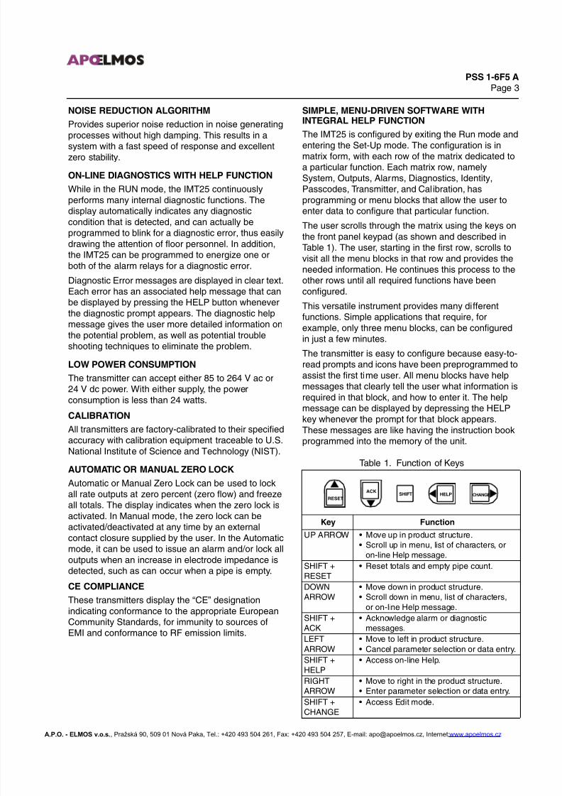
Table 1. Function of Keys
Key Function
UP ARROW • Move up in product structure.• Scroll up in menu, list of characters, or
on-line Help message.SHIFT +RESET
• Reset totals and empty pipe count.
DOWNARROW
• Move down in product structure.• Scroll down in menu, list of characters,
or on-line Help message.
SHIFT +ACK
• Acknowledge alarm or diagnosticmessages.
LEFT
ARROW
• Move to left in product structure.
• Cancel parameter selection or data entry.
SHIFT +HELP
• Access on-line Help.
RIGHTARROW
• Move to right in the product structure.• Enter parameter selection or data entry.
SHIFT +CHANGE
• Access Edit mode.
RESETHELPSHIFT CHANGE
ACK
A.P.O. - ELMOS v.o.s., Pražská 90, 509 01 Nová Paka, Tel.: +420 493 504 261, Fax: +420 493 504 257, E-mail: [email protected], Internet:www.apoelmos.cz

7/27/2019 Flow Transmitter Foxboro.pdf
http://slidepdf.com/reader/full/flow-transmitter-foxboropdf 4/14
PSS 1-6F5 APage 4
FRONT PANEL OPTIONS
A display/keypad, a protective cover with a clear
plastic window guard, and an I/O access port withcover are front panel options. See Figure 2.
The display consists of a 2-line, 16 characters perline, back-lighted LCD indicator. The characters are10 mm (0.4 in) high and can indicate positive total,negative total, net total, net inventory total, and rate inconventional flow units. A “+” or “–” indicates flowdirection. The keypad has five keys as previouslydescribed in Table 1. This option allows thetransmitter to be used as a stand-alone unit and givesthe user complete operation and configurationcapabilities.
The cover with a clear plastic window protects thedisplay/keypad during washdown operations andprevents inadvertent activation of the buttons by thewashdown stream. However, the front panel isprotected to NEMA 4X even without the cover.
Figure 2. Front Panel Options
The circular I/O access port has a cover integrallyconnected to the panel to prevent loss or
misplacement. Loosening a screw on the coverprovides access to two banana plug sockets. Thesesockets allow direct connection to either FoxCom orHART Communication protocols. This option negatesthe need to remove the housing cover to access theabove terminals.
OPERATING CONDITIONS
(a) Process temperature is not applicable to pipe- or surface-mounted transmitters. However, with flowtube mounting, the ambient
temperature operative limit of 70°C (158°F) must not be exceeded. Also, the process temperature is limited to 121°C (250°F).
(b) During transportation and storage, the ambient temperature limits are -40 and +85°C (-40 and 185°F) without an LCD Indicator; and
-30 and +80°C (-22 and +176°F) with an LCD Indicator.
(c) Relative humidity limits listed apply only with transmitter covers properly installed.(d) During transmitter transportation or storage, the relative humidity limit is 0 and 100% with transmitter covers properly installed.
(e) During transportation, the packaged transmitter can withstand normal handling and shipping conditions without damage.
IMT25
PROTECTIVE COVER WITH
WINDOW HINGES UPWARD
2-LINEDISPLAY
5-BUTTONKEYPAD
I/O ACCESSPORT AND COVER
Transmitter Influence
Reference Operating
Conditions
Normal Operating
Condition Limits Operative Limits
Ambient Temperature(a)without LCD Indicator
23 ±2°C (73 ±3°F) -20 and +55°C(-4 and +131°F)
-30 and +70°C(b)(-22 and +158°F)(b)
Ambient Temperature(a)with LCD Indicator
23 ±2°C (73 ±3°F) -20 and +55°C(-4 and +131°F)
-20 and +70°C(b)(-4 and +158°F)(b)
Process Temperature(a) 23 ±2°C (73 ±3°F) See Note (a) See Note (a)
Relative Humidity 50 ±10% 5 and 100%(c) 5 and 100%(c,d)
Supply Voltage• ac Voltage• dc Voltage
• 120 V ac, 240 V ac• 24 V dc, 1.5 A min.
• 85 and 264 V ac• Rated Voltage ±20%
• 85 and 264 V ac• Rated Voltage ±20%
Supply Frequency 50 or 60 Hz Rated Frequency ±3 Hz 47 and 63 Hz
4 to 20 mA Output• Supply Voltage• Load
• 24 V dc• 250 Ω
• 12 and 50 V dc• 0 and 1950 Ω
• 12 and 50 V dc• 0 and 1950 Ω
Pulse Output• Supply Voltage• Load
• 24 V dc• 480 Ω
• 5 and 42 V dc• 1 and 80 mA dc
• 5 and 42 V dc• 1 and 80 mA dc
Vibration Negligible 0 and 5 m/s2 (0 and 0.5 “g”)from 5 to 500 Hz
5 m/s2 (0.5 “g”)(e)up to 500 Hz
A.P.O. - ELMOS v.o.s., Pražská 90, 509 01 Nová Paka, Tel.: +420 493 504 261, Fax: +420 493 504 257, E-mail: [email protected], Internet:www.apoelmos.cz
7/27/2019 Flow Transmitter Foxboro.pdf
http://slidepdf.com/reader/full/flow-transmitter-foxboropdf 5/14
PSS 1-6F5 APage 5
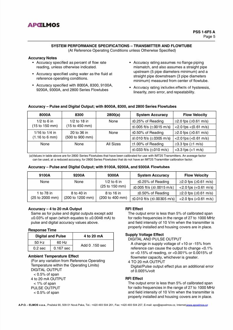
SYSTEM PERFORMANCE SPECIFICATIONS – TRANSMITTER AND FLOWTUBE(At Reference Operating Conditions unless Otherwise Specified)
Accuracy Notes• Accuracy specified as percent of flow rate
reading, unless otherwise indicated.
• Accuracy specified using water as the fluid atreference operating conditions.
• Accuracy specified with 8000A, 8300, 9100A,9200A, 9300A, and 2800 Series Flowtubes
• Accuracy rating assumes no flange pipingmismatch, and also assumes a straight pipeupstream (5 pipe diameters minimum) and astraight pipe downstream (3 pipe diametersminimum) measured from center of flowtube.
• Accuracy rating includes effects of hysteresis,linearity, zero error, and repeatability.
Accuracy – Pulse and Digital Output; with 8000A, 8300, and 2800 Series Flowtubes
Accuracy – Pulse and Digital Output; with 9100A, 9200A, and 9300A Flowtubes
Accuracy – 4 to 20 mA OutputSame as for pulse and digital outputs except add±0.03% of span (which equates to ±0.0048 mA) topulse and digital accuracy values above.
Response Time
Ambient Temperature Effect(For any variation from Reference OperatingTemperature within the Operating Limits)DIGITAL OUTPUT
< 0.5% of span4 to 20 mA OUTPUT
< 1% of span
PULSE OUTPUT< 0.5% of span
RFI EffectThe output error is less than 5% of calibrated spanfor radio frequencies in the range of 27 to 1000 MHzand field intensity of 10 V/m when the transmitter isproperly installed and housing covers are in place.
Supply Voltage EffectDIGITAL AND PULSE OUTPUT
A change in supply voltage of +10 or -15% fromreference can cause the output to change <0.1%or <0.15% of reading, or <0.001% or 0.0015% offlowmeter capacity, whichever is greater.
4 TO 20 mA OUTPUTDigital/Pulse output effect plus an additional errorof 0.005%/volt
RFI EffectThe output error is less than 5% of calibrated span
for radio frequencies in the range of 27 to 1000 MHzand field intensity of 10 V/m when the transmitter isproperly installed and housing covers are in place.
8000A 8300 2800(a) System Accuracy Flow Velocity1/2 to 6 in
(15 to 150 mm)1/2 to 18 in
(15 to 450 mm)None ±0.25% of Reading ≥2.0 fps (≥0.61 m/s)
±0.005 ft/s (±.0015 m/s) <2.0 fps <(0.61 m/s)
1/16 to 1/4 in(1.16 to 6 mm)
20 to 36 in(500 to 900 mm)
None ±0.50% of Reading ≥2.0 fps (≥0.61 m/s)
±0.010 ft/s (±.0305 m/s) <2.0 fps (<0.61 m/s)
None None All Sizes ±1.00% of Reading ≥3.3 fps (≥1 m/s)
±0.033 ft/s (±.010 m/s) <3.3 fps (<1 m/s)
(a)Values in table above are for 2800 Series Flowtubes that have been calibrated for use with IMT25 Transmitters. An average factor
can be used, at a reduced accuracy, for 2800 Series Flowtubes that do not have an IMT25 Transmitter calibration factor.
9100A 9200A 9300A System Accuracy Flow Velocity
None None 1/2 to 6 in(25 to 150 mm)
±0.25% of Reading ≥2.0 fps (≥0.61 m/s)
±0.005 ft/s (±0.0015 m/s) <2.0 fps (<0.61 m/s)
1 to 78 in(25 to 2000 mm)
8 to 40 in(200 to 1200 mm)
8 to 16 in(200 to 400 mm)
±0.50% of Reading ≥2.0 fps (≥0.61 m/s)
±0.010 ft/s (±0.00305 m/s) <2.0 fps (<0.61 m/s)
Digital and Pulse 4 to 20 mA
50 Hz 60 HzAdd 0 .150 sec
0.2 sec 0.167 sec
A.P.O. - ELMOS v.o.s., Pražská 90, 509 01 Nová Paka, Tel.: +420 493 504 261, Fax: +420 493 504 257, E-mail: [email protected], Internet:www.apoelmos.cz

7/27/2019 Flow Transmitter Foxboro.pdf
http://slidepdf.com/reader/full/flow-transmitter-foxboropdf 6/14
PSS 1-6F5 APage 6
PERFORMANCE SPECIFICATIONS (Cont.)
Switching and Indirect Lightning Transients
Can withstand 1000 V common mode and 500 Vnormal mode, 1.2 x 20 µs impulse per ANSI/IEEEStandard C62.41-1980 and IEC Standard 801-5.
High Frequency TransientsCan withstand a high frequency transient of 2000 Vcommon mode, 5 x 50 ns impulse (IEC Std. 801-4).
Electrostatic DischargeCan withstand application of 6000 V contactdischarge, or 8000 V air discharge of an electrostaticfield per IEC Standard 801-2.
European Union Directives
• Complies with Electromagnetic CompatibilityRequirements of European EMC Directive89/336/EEC by conforming to the followingCENELEC and IEC Standards: EN 50081-2,EN 50082-2, and IEC 801-2 through 801-6.
• Complies with NAMUR Part 1 InterferenceImmunity Requirement (EMC).
• Conforms to Applicable European UnionDirectives (“CE” Logo marked on product)
FUNCTIONAL SPECIFICATIONS
Flow Velocity LimitsLOW FLOW CUTOFF (For Rate Indicator, PulseOutputs, and Digital Outputs)
0.01 m/s (0.033 ft/s)MAXIMUM VELOCITY
10 m/s (33 ft/s)MINIMUM URV (Upper Range Value)
0.5 m/s (1.65 ft/s)
MeasurementsBIDIRECTIONAL FLOW
“+” or “-” rate in engineering units“+” or “-” rate in % of URV
TOTALIZATION“+” or “-” bidirectional total, 8 digitsNet total, 8 digitsNet inventory total, 10 digits
Power ConsumptionLess than 24 W at reference voltage and frequency
Output DampingField-programmable from 0.1 to 49.9 seconds. This
feature is used for reducing the frequency responseof the transmitter as required by the process.
Automatic Zero Lock (Empty Tube Zero)This function automatically drives the analog, pulse,and digital output signals to zero flow rate when theflowtube's electrodes become uncovered by theconductive liquid.
RangingThe transmitter is easily adjusted for the desired flowrate units and to the required upper range value.This range data may also be keyed in through an
external configurator, or optional LCD indicator andkeypad.
Preset/CalibrationThe transmitter may be used as an analog or pulsegenerating source to check and/or calibrate otherinstruments in the output loop, such as indicators,controllers, and recorders. This feature may beactivated locally by pressing pushbuttons. Theoutput signals can also be adjusted to any value,remotely, via an external configurator.
Self-TestDuring power up and periodically during normaloperations, the electronics will self-test the system toidentify the presence of any faults, and isolate thefault to the transmitter or flowtube.
Test ModeTransmitter calibration accuracy can be verifiedusing a Foxboro Model IMTSIM Magnetic FlowSimulator. The IMT25 has a Test mode to facilitatethe test and provide a way to log the test date intothe transmitter. (See PSS 1-6F7 A for moreinformation on the Model IMTSIM Magnetic FlowSimulator.)
Low Flow Cut-OffA low flow cut-off algorithm stops the pulse output,rate indicator, and digital measurement value whenthe measurement signal falls below a velocity of0.033 ft/s. Note that there is no low flow cut-off with4 to 20 mA current output.
A.P.O. - ELMOS v.o.s., Pražská 90, 509 01 Nová Paka, Tel.: +420 493 504 261, Fax: +420 493 504 257, E-mail: [email protected], Internet:www.apoelmos.cz

7/27/2019 Flow Transmitter Foxboro.pdf
http://slidepdf.com/reader/full/flow-transmitter-foxboropdf 7/14
PSS 1-6F5 APage 7
Output SignalsThree electrical output signals are available - Digital,4 to 20 mA, and Pulse. The Digital Output utilizeseither FoxCom or HART protocol. All three outputsignals are available simultaneously except that the4 to 20 mA output is not available with 4800 baudFoxCom, or when HART is configured for Multidropoperation.DIGITAL OUTPUT (4800 Baud)
Transmitter transfers digital information usingFoxCom communication protocol.
4 TO 20 mA OUTPUT WITH SUPERIMPOSEDDIGITAL OUTPUT (600 Baud FoxCom or1200 Baud HART)
The current output is independently isolated and
can be internally or externally powered. The cur-rent output is also configurable to a 4 to 12 and12 to 20 mA split range for bidirectional flow appli-cations. Minimum current is 3.9 mA and maximumcurrent is 22 mA.
PULSE OUTPUTThis is a 2-wire solid state type output, and isconfigurable as a scaled pulse or frequency output.Pulse output is available simultaneously with 4 to20 mA or digital output.Scaled Pulse Output Mode
Frequency Output Mode (Unidirectional Only)
0 Hz to either 1, 2, 5, or 10 kHz, userprogrammable
Contact InputsQuantity: 2Type:
Requires current sinking device such as contactclosure or transistor switch between terminal blockconnections provided. The contact inputs share
the same circuit reference, but are isolated fromthe flowtube ground.
Voltage Rating (Open Circuit Voltage):24 V dc, ±15%
Current (Closed Circuit Current):12 mA, ±15%
Relay OutputsQuantity: 2Type: Relay, 1 form A (isolated)Voltage Rating:
60 V dc maximum30 V ac rms maximum
Current Rating:3 amps maximum resistive
Supply Voltage – 4 to 20 mA Output4 TO 20 mA OUTPUT–INTERNALLY POWERED
Output may share the same circuit reference asthe pulse output, if pulse output is also internallypowered. This circuit reference may only begrounded in one location.
4 TO 20 mA OUTPUT–EXTERNALLY POWEREDAnalog output is independently isolated from fluidground. Refer to Figure 3 for a graph of externalsupply voltage vs. output load resistance.
Figure 3. 4 to 20 mA Output, ExternalSupply Voltage vs. Output Load Resistance
Transmitter Voltage120 or 240 V ac, 50 or 60 Hz; or 24 V dc
Digital OutputPowered by transmitter, or by the I/A Series System
SpeedSelection Pulse Width
MaximumFrequency
Slow 50.0 ms 10 Hz
Medium 5.0 ms 100 Hz
Voltage
Load Resistance
Range(a)
24 V dc ±15% 0 to 500 Ω(a) A 200 Ω load resistor is required to allow
communications.
R MAX
V S 10 –
0.0205 --------------------- Ω=
Transmitter will function with output load less than250 Ω provided an external configurator is notconnected to it. Connecting an external configuratorwhile operating in this area may cause disturbancesand/or communication problems.
2000
1800
1600
1400
1200
1000
800
600
400
200
0
1950
0 10 20 30 40 50
TYPICAL SUPPLY VOLTAGEAND LOAD LIMITS
V dc243032
LIMITS (Ω)250 & 683250 & 976250 & 1073
M A X
I M U M
L O A D
( R M A X )
FoxCom or HARTMIN LOAD
SEE NOTE BELOW
OPERATINGAREA
O U T P U T
L O A D
R E S I S T A N C E , Ω
EXTERNAL SUPPLY VOLTAGE (Vs), V dc
250
NOTE
A.P.O. - ELMOS v.o.s., Pražská 90, 509 01 Nová Paka, Tel.: +420 493 504 261, Fax: +420 493 504 257, E-mail: [email protected], Internet:www.apoelmos.cz

7/27/2019 Flow Transmitter Foxboro.pdf
http://slidepdf.com/reader/full/flow-transmitter-foxboropdf 8/14
PSS 1-6F5 APage 8
FUNCTIONAL SPECIFICATIONS (Cont.)
Pulse Output – Internally Powered
Pulse output may share the same circuit referenceas the current output. This circuit reference can onlybe grounded in one location.VOLTAGE
24 V dc ±15%CURRENT
1 mA minimum to 80 mA maximumOFF-STATE LEAKAGE
200 µA maximum
Pulse Output – Externally PoweredOutput is independently isolated from fluid ground.VOLTAGE
5 to 42 V dcCURRENT
1 mA minimum to 80 mA maximumOFF-STATE LEAKAGE
200 µA maximum
Diagnostics and AlarmsThe transmitter provides internal diagnostics andconfigurable alarm functions (low flow, high flow, andhigh totals). The display automatically indicates anyexisting diagnostic or alarm condition. The relay out-puts can be configured to activate on an alarm ordiagnostic condition to provide remote indication of
such events. Also, the analog output can be config-ured to go upscale, downscale, or remain activewhen an alarm condition exists. For diagnostic con-ditions, the analog output can be configured to godownscale or upscale. Diagnostics and alarms arealso communicated via the Digital Output.
Multidrop Communications (HART Only)Either point-to-point (one transmitter) ormultidropping is permitted. Multidropping is theconnection of several transmitters to a singlecommunications line. Communication between thehost computer and transmitters occurs digitally with
analog output of transmitter deactivated. With HARTcommunications protocol, up to fifteen transmitterscan be connected on a single twisted pair of wires orover leased telephone lines. The maximum cablelength conforms to the HART Physical LayerSpecification and will vary according to thecharacteristics of the individual transmitters in amultidrop environment.
Digital Communications
The transmitter communicates bidirectionally overthe field wiring to the PC-based Configurator or theHART Communicator (installed anywhere in a Divi-sion 2 area along the 4 to 20 mA loop). The FoxComversion also allows communication to a Foxboro PC-based Configurator, and/or the I/A Series System.Using the local display/keypad, or digital communi-cations, the functions that can be performed are:• Display/Reconfigure Measurement Information
– Flow Rate in EGUs– Flow Rate in % of URV– Flow Direction– Forward, Reverse, Net, and Grand Total
– Flow Rate Damping– Meter Factor (Calibration Factor)
• Display/Reconfigure Transmitter Status andConfiguration– Transmitter Output Mode (FoxCom Only)– Outputs (Uni/Bidirectional, Dual, Multi, or Split
Range– Alarm Functions, Set Points, and Deadbands– Noise Reduction– Automatic Zero Lock– Output Response to Alarms/Diagnostics– Passcodes Protection– Contact Inputs Status and Function– Contact Output Status and Function
• Display/Reconfigure Transmitter Identity– Flowtube Model Number– Flowtube Serial Number– Tag Information– Poll Address (HART Only)
• Display/Operate Diagnostic and CalibrationFunctions– 4 to 20 mA and Pulse Output Preset– 4 to 20 mA Calibration– Online Diagnostics
Communications FormatBoth FoxCom and HART protocols are based uponthe FSK (Frequency Shift Keying) technique. TheFSK tones are superimposed on the transmitter4 to 20 mA output leads. Communication betweenthe external configurator and the transmitter doesnot disturb the output signal. The followingparagraphs describe the 4 to 20 mA output withsuperimposed digital output (FoxCom and HART),and the digital output signal with FoxCom only.
A.P.O. - ELMOS v.o.s., Pražská 90, 509 01 Nová Paka, Tel.: +420 493 504 261, Fax: +420 493 504 257, E-mail: [email protected], Internet:www.apoelmos.cz
7/27/2019 Flow Transmitter Foxboro.pdf
http://slidepdf.com/reader/full/flow-transmitter-foxboropdf 9/14
PSS 1-6F5 APage 9
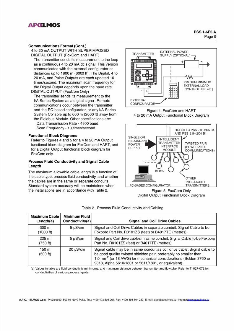
Communications Format (Cont.)4 to 20 mA OUTPUT WITH SUPERIMPOSEDDIGITAL OUTPUT (FoxCom and HART)
The transmitter sends its measurement to the loopas a continuous 4 to 20 mA dc signal. This versioncommunicates with the external configurator atdistances up to 1800 m (6000 ft). The Digital, 4 to20 mA, and Pulse Outputs are each updated 10times/second. The maximum scan frequency forthe Digital Output depends upon the baud rate.
DIGITAL OUTPUT (FoxCom Only)The transmitter sends its measurement to theI/A Series System as a digital signal. Remotecommunications occur between the transmitterand the PC-based configurator, or any I/A Series
System Console up to 600 m (2000 ft) away fromthe Fieldbus Module. Other specifications are:Data Transmission Rate - 4800 baudScan Frequency - 10 times/second
Functional Block DiagramsRefer to Figures 4 and 5 for a 4 to 20 mA Outputfunctional block diagram for FoxCom and HART, andfor a Digital Output functional block diagram forFoxCom only.
Process Fluid Conductivity and Signal CableLength
The maximum allowable cable length is a function ofthe cable type, process fluid conductivity, and whetherthe cables are in the same or separate conduits.Standard system accuracy will be maintained whenthe installations are in accordance with Table 2.
Figure 4. FoxCom and HART
4 to 20 mA Output Functional Block Diagram
Figure 5. FoxCom OnlyDigital Output Functional Block Diagram
Table 2. Process Fluid Conductivity and Cabling
IMT25
TRANSMITTEREXTERNAL POWERSUPPLY (OPTIONAL)
EXTERNALCONFIGURATOR
250 OHM MINIMUMEXTERNAL LOAD(CONTROLLER, etc.)
+
+
INTELLIGENTTRANSMITTER
INTERFACEMODULE
SINGLE ORREDUNDANTPOWERSUPPLY
PC-BASED CONFIGURATOR
IMT25
REFER TO PSS 21H-2D5 B4AND PSS 21H-2C4 B4
TWISTED PAIR(POWER ANDCOMMUNICATIONS)
OTHERINTELLIGENTTRANSMITTERS
Maximum Cable
Length(a)
Minimum Fluid
Conductivity(a) Signal and Coil Drive Cables
300 m
(1000 ft)
5 µS/cm Signal and Coil Drive Cables in separate conduit. Signal Cable to be
Foxboro Part No. R0101ZS (feet) or B4017TE (metres).
225 m(750 ft)
5 µS/cm Signal and Coil drive cables in same conduit. Signal Cable to be FoxboroPart No. R0101ZS (feet) or B4017TE (metres).
150 m(500 ft)
20 µS/cm Signal cable may be in same conduit as coil drive cable. Signal cable tobe good quality twisted shielded pair, preferably no smaller than1.0 mm2 (or 18 AWG) for mechanical considerations (Belden 8760 or9318, Alpha 5610/1801 or 5611/1801, or equivalent).
(a) Values in table are fluid conductivity minimums, and maximum distance between transmitter and flowtube. Refer to TI 027-072 for
conductivities of various process liquids.
A.P.O. - ELMOS v.o.s., Pražská 90, 509 01 Nová Paka, Tel.: +420 493 504 261, Fax: +420 493 504 257, E-mail: [email protected], Internet:www.apoelmos.cz

7/27/2019 Flow Transmitter Foxboro.pdf
http://slidepdf.com/reader/full/flow-transmitter-foxboropdf 10/14
PSS 1-6F5 APage 10
PHYSICAL SPECIFICATIONS
Transmitter Enclosure
The standard enclosure is a single compartmentdesign which houses the electronics, power supply,and all field terminations. Provisions for four stan-dard conduit/cable access holes (nonthreadedholes) are sized to accept 1/2 NPS or M20 fittings.These standard holes are located as indicated in the“Dimensions – Nominal” section. Two or fouroptional conduit/cable access holes can also be pro-vided as indicated in the “Optional Selections andAccessories” section. The enclosure compartment isprotected with a front gasketed cover which sealsthe unit. Upon removing the cover, a lanyardattached to both inside surfaces (of the cover and
enclosure) retains the cover, thereby eliminating themisplacing or otherwise damaging of the coverassembly. This cast aluminum enclosure is weather-proof as defined by IEC IP66, and provides thewatertight and corrosion resistant protection ofNEMA Type 4X. Refer to the Optional Features sec-tion for information relating to a dual compartmentenclosure that separates the field terminals from allother transmitter electronics.
Enclosure MaterialCast aluminum (1% copper content, maximum)
Enclosure FinishEpoxy powder coat, gray
Transmitter Mounting
PIPE MOUNTINGTwo integrally cast flanges at the top and bottomrear of the enclosure, together with a kit ofstainless steel parts (by Foxboro), are used formounting transmitter to a DIN 50 or 2 in pipe.
SURFACE MOUNTINGThe two integral flanges used for pipe mountingcan also be used to secure the transmitter to a wallor surface.
FLOWTUBE MOUNTINGThis type of mounting is only applicable totransmitters used with 8000A and 9300A SeriesFlowtubes. In these installations, the transmitter is
secured to the top surface of the flowtube using amounting bracket and gasket seal.
Mounting PositionThe transmitter can be mounted in any positionwithout degrading performance. The front cover ofthe transmitter housing can be rotated in 90°increments to allow easy viewing of the display forany installation orientation.
Approximate Mass - Transmitter OnlySINGLE COMPARTMENT TRANSMITTER
2.9 kg (6.5 lb)
DUAL COMPARTMENT TRANSMITTER3.9 kg (8.7 lb)
INTRINSICALLY SAFE TRANSMITTER4.9 kg (10.9 lb)
ELECTRICAL SAFETY SPECIFICATIONS
Testing Laboratory, Types of Protection,
and Area Classification Application Conditions
Electrical Safety
Design Code
CSA ordinary locations. — K
CSA Class I, Division 2, Groups A, B, C, and D; Class II,Division 2, Groups F and G; and Class III, Division 2hazardous locations.
Temperature Class T4 atmaximum ambient of 70°C.
L
FM ordinary locations. — M
FM nonincendive, Class I, Division 2, Groups A, B, C, and D;Class II, Division 2, Groups F and G; and Class III, Division 2hazardous locations
Temperature Class T4 atmaximum ambient of 70°C.
N
Testing Laboratory Approval or Certification not Required. — Z
A.P.O. - ELMOS v.o.s., Pražská 90, 509 01 Nová Paka, Tel.: +420 493 504 261, Fax: +420 493 504 257, E-mail: [email protected], Internet:www.apoelmos.cz
7/27/2019 Flow Transmitter Foxboro.pdf
http://slidepdf.com/reader/full/flow-transmitter-foxboropdf 11/14
PSS 1-6F5 APage 11
OPTIONAL SELECTIONS AND ACCESSORIES
I/O Access Port and Cover
An I/O access port and cover allow access to twobanana plugs that are provided for connection to thehand-held terminals or PC-based configurators. Theaccess port cover not only protects the terminalsfrom the environment, but is also marked to identifyterminal functions. The cover is integrally attached tothe front panel, thus preventing misplacement andloss of the cover when removed. Specify OptionalSelection suffix -A.
Protective Cover for Display and Keypad PanelThis hinged clear plastic cover protects the frontpanel display and keypad. The cover protects
against inadvertent manipulation of the keys, andallows for “hose downs” of the transmitter housing.Specify Optional Selection suffix -B.
Dual Compartment Enclosure
An optional secondary enclosure is available forthose installations which require a sealed separationbetween the electronics and the field terminations.With this option, a separate field terminals compart-ment is provided which is sealed and separated fromthe primary electronics compartment. Therefore, allfield terminations can be made by simply removingthe terminations compartment cover without having
to expose the electronics to the environment. Theterminal strips contained in the secondary housingallow for easy wiring, installation, and replacement.Specify Optional suffix -C for a secondary housingwith top insertion type terminal block, or Suffix -D fora secondary housing with lug type terminal block.
Cable Glands for Nonconduit ApplicationsThese 1/2 NPT cable glands provide a rain tight,strain relieved entrance for 6.8 to 12.2 mm (0.27 to0.48 in) diameter cable. The body and seal nut arenylon and the compression gland is neoprene.Selectable using Model Code Option -G.
Foxboro Signal Cable
For Remote-Mounted Transmitter only. Two-core(two-conductor), multiscreened (multi-shielded)cable with two driven screens (shields). Maximumlength is 300 m (1000 ft). If expressing length infeet, order Part Number R0101ZS. If length units aremetres, order Part Number B4017TE. Refer toTable 2 for recommended installation of this cable.
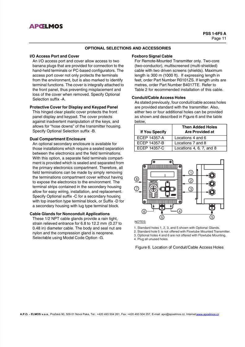
Conduit/Cable Access HolesAs stated previously, four conduit/cable access holesare provided standard with the transmitter. Also,either two or four additional holes can be providedas shown and described in Figure 6 and the table
below,
Figure 6. Location of Conduit/Cable Access Holes
If You Specify
Then Added Holes
Are Provided at
ECEP 14357-A Locations 4 and 6
ECEP 14357-B Locations 7 and 8
ECEP 14357-C Locations 4, 6, 7, and 8
IMT25
8
7
6 4
5 5
1
2
3
NOTES:
1. Standard holes 1, 2, 3, and 5 shown with Optional Glands.2. Standard hole 5 is not offered with Flowtube Mounted Transmitter.3. Optional holes 4 and 6 are not offered with Flowtube Mounting.4. Plug all unused holes.
A.P.O. - ELMOS v.o.s., Pražská 90, 509 01 Nová Paka, Tel.: +420 493 504 261, Fax: +420 493 504 257, E-mail: [email protected], Internet:www.apoelmos.cz
7/27/2019 Flow Transmitter Foxboro.pdf
http://slidepdf.com/reader/full/flow-transmitter-foxboropdf 12/14
PSS 1-6F5 APage 12
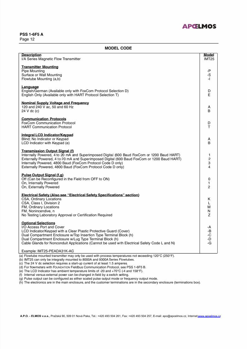
(a) Flowtube mounted transmitter may only be used with process temperatures not exceeding 120°C (250°F).(b) IMT25 can only be integrally mounted to 8000A and 9300A Series Flowtubes.(c) The 24 V dc selection requires a start-up current of at least 1.5 amperes.(d) For flowmeters with FOUNDATION Fieldbus Communication Protocol, see PSS 1-6F5 B.(e) The LCD Indicator has ambient temperature limits of -20 and +70°C (-4 and 158°F).(f) Internal versus external power can be changed in field by a switch setting.(g) Pulse output can be configured as either scaled pulse output mode or frequency output mode.(h) The electronics are in the main enclosure, and the customer terminations are in the secondary enclosure (terminations box).
MODEL CODE
Description ModelI/A Series Magnetic Flow Transmitter IMT25
Transmitter MountingPipe Mounting -PSurface or Wall Mounting -SFlowtube Mounting (a,b) -I
LanguageEnglish/German (Available only with FoxCom Protocol Selection D) DEnglish Only (Available only with HART Protocol Selection T) E
Nominal Supply Voltage and Frequency120 and 240 V ac, 50 and 60 Hz A24 V dc (c) B
Communication Protocols
FoxCom Communication Protocol DHART Communication Protocol T
Integral LCD Indicator/KeypadBlind; No Indicator or Keypad ALCD Indicator with Keypad (e) B
Transmission Output Signal (f)Internally Powered, 4 to 20 mA and Superimposed Digital (600 Baud FoxCom or 1200 Baud HART) 1Externally Powered, 4 to 20 mA and Superimposed Digital (600 Baud FoxCom or 1200 Baud HART) 2Internally Powered, 4800 Baud (FoxCom Protocol Code D only) 3Externally Powered, 4800 Baud (FoxCom Protocol Code D only) 4
Pulse Output Signal (f,g)Off (Can be Reconfigured in the Field from OFF to ON) 0
On, Internally Powered 1On, Externally Powered 2
Electrical Safety (Also see “Electrical Safety Specifications” section)CSA, Ordinary Locations KCSA, Class I, Division 2 LFM, Ordinary Locations MFM, Nonincendive, n NNo Testing Laboratory Approval or Certification Required Z
Optional SelectionsI/O Access Port and Cover -ALCD Indicator/Keypad with a Clear Plastic Protective Guard (Cover) -BDual Compartment Enclosure w/Top Insertion Type Terminal Block (h) -CDual Compartment Enclosure w/Lug Type Terminal Block (h) -D
Cable Glands for Nonconduit Applications (Cannot be used with Electrical Safety Code L and N) -G
Example: IMT25-PEADA31K-AG
A.P.O. - ELMOS v.o.s., Pražská 90, 509 01 Nová Paka, Tel.: +420 493 504 261, Fax: +420 493 504 257, E-mail: [email protected], Internet:www.apoelmos.cz

7/27/2019 Flow Transmitter Foxboro.pdf
http://slidepdf.com/reader/full/flow-transmitter-foxboropdf 13/14
PSS 1-6F5 APage 13
DIMENSIONS–NOMINAL
IMT25
OPTIONALCABLE GLANDSFOR NONCONDUITAPPLICATIONS.NONTHREADEDHOLES (3) ARE22 mm (0.866 in)DIAMETER. PLUGUNUSED HOLES.SEE NOTE 1.
OPTIONALI/O ACCESSPORT ANDCOVER
1656.5
SQUARE2449.6
1224.8OPTIONAL
DISPLAY
OPTIONALKEYPAD
OPTIONALPROTECTIVECOVER LIFTSUPWARD
SQUARE HOLE PATTERN
ALLOWS 90˚ ROTATIONOF COVER. CAPTIVESCREWS ARE USED.
1857.3
MOUNTING BRACKET PART OFFLOWTUBE ASSEMBLY. TRANSMITTERMOUNTED TO BRACKET BY MEANS OFA 1/2 NPT NUT AND LOCKING WASHER
FLUID GROUNDCONNECTION
WAFER BODYFLOWTUBE(8001A-WCI)SHOWN. SEEAPPLICABLEFLOWTUBEDOCUMENTSFOR DIMENSIONS.
DATA PLATE
ELECTRONICSCOMPARTMENT
FLOWTUBE MOUNTED TRANSMITTER - OPTIONAL DUAL COMPARTMENT
mm
in
IMT25
26710.5
OPTIONAL CABLEGLANDS FORNONCONDUITAPPLICATIONS,THREE PLACES.NONTHREADEDHOLES ARE22 mm (0.866 in)DIAMETER. PLUGUNUSED HOLES.SEE NOTE 1.
FIELD TERMINALSCOMPARTMENT
FLUID GROUNDCONNECTION
FLANGED FLOWTUBE (931HA)SHOWN. SEE APPLICABLEFLOWTUBE DOCUMENTSFOR DIMENSIONS.
MOUNTINGBRACKET
PART OFFLOWTUBEASSEMBLY.SEE NOTE 4.
DATA PLATE
ELECTRONICSCOMPARTMENT
1. PLUG UNUSED CONDUIT CONNECTIONS (OR HOLES) WITH PLUGS TO MAINTAIN NEMA 4 MOISTUREAND DUST PROTECTION (SEE MI 021-387).
2. SIGNAL AND COIL DRIVE WIRING BETWEEN TRANSMITTER AND FLOWTUBE ARE PERFORMED BYFOXBORO AT PLANT OF MANUFACTURE WHEN BOTH UNITS ENTERED ON SAME ORDER.
3. SEE "OPTIONAL SELECTIONS" SECTION IF ADDITIONAL CONDUIT/CABLE ACCESS HOLES ARE REQUIRED.
4. FLOWTUBE ASSEMBLY MOUNTED AT FACTORY IN POSITION SHOWN, AND CAN BE ROTATED 1/4 TURN.FACTORY-MOUNTED POSITION RECOMMENDED FOR 3 INCH AND SMALLER 8000A SERIES FLOWTUBES.
NOTES:
+
FLOWTUBE MOUNTED TRANSMITTER - SINGLE COMPARTMENT
SEE NOTE 4.
A.P.O. - ELMOS v.o.s., Pražská 90, 509 01 Nová Paka, Tel.: +420 493 504 261, Fax: +420 493 504 257, E-mail: [email protected], Internet:www.apoelmos.cz

7/27/2019 Flow Transmitter Foxboro.pdf
http://slidepdf.com/reader/full/flow-transmitter-foxboropdf 14/14
PSS 1-6F5 APage 14
DIMENSIONS–NOMINAL (Cont.)
SURFACE AND PIPE MOUNTED TRANSMITTER - SINGLE COMPARTMENT
IMT25
OPTIONALDISPLAY
OPTIONALKEYPAD
OPTIONALI/O ACCESSPORT ANDCOVER
SQUARE HOLE PATTERNALLOWS 90˚ ROTATIONOF COVER. CAPTIVESCREWS ARE USED.
8.86 mm (0.35 in)DIAMETER HOLES FOURPLACES ON FLANGES;FOR SURFACE AND PIPEMOUNTING.
1656.5
481.9
69.92.75
SQUARE
187.47.38
2068.1 OPTIONAL
PROTECTIVECOVER LIFTSUPWARD
2449.6
1224.8
NOMINAL DN 50OR 2 in PIPEPROVIDED BYUSER
OPTIONAL CABLE GLANDSFOR NONCONDUITAPPLICATIONS.NONTHREADED HOLESARE 22 mm (0.866 in)DIAMETER. PLUG UNUSEDHOLES. SEE NOTE 1.
HARDWAREFOR SURFACEMOUNTINGPROVIDED BYUSER
HARDWAREFOR PIPEMOUNTINGPROVIDEDBY FOXBORO
IMT25
26710.5
ELECTRONICSCOMPARTMENT
MOUNTINGSURFACE
OPTIONAL CABLEGLANDS FORNONCONDUITAPPLICATIONS,FOUR PLACES.NONTHREADEDHOLES ARE
22 mm (0.866 in)DIAMETER. PLUGUNUSED HOLES.SEE NOTE.
FIELD TERMINALSCOMPARTMENTVERTICAL DN 50 OR
2 in PIPE MOUNTING
1. PLUG UNUSED CONDUIT CONNECTIONS (OR HOLES) WITH PLUGS TO MAINTAIN NEMA 4 MOISTUREAND DUST PROTECTION (SEE MI 021-387).
2. SEE "OPTIONAL SELECTIONS" SECTION IF ADDITIONAL CONDUIT/CABLE ACCESS HOLES AREREQUIRED.
NOTES:
SURFACE AND PIPE MOUNTED TRANSMITTER - OPTIONAL DUAL COMPARTMENTSURFACE AND PIPE MOUNTED TRANSMITTER - OPTIONAL DUAL COMPARTMENT
A.P.O. - ELMOS v.o.s., Pražská 90, 509 01 Nová Paka, Tel.: +420 493 504 261, Fax: +420 493 504 257, E-mail: [email protected], Internet:www.apoelmos.cz