flow through pipe orifices at low reynolds...
TRANSCRIPT

231
Flow through Pipe Orifices at Low Reynolds Numbers.By F. C. J o h a n se n , B.Sc., A.M.I.Mech.E.
(Communicated by R. V. Southwell, F.R.S.—Received October 1, 1929.)
[Plates 3, 4.]
Introduction. *
Most of the experimental work in connection with the flow of fluids through diaphragm orifices in pipe lines has been directed to the establishment of the orifice as a flow meter, and has been carried out at the velocities of flow commonly encoimtered in commercial practice. As a result of such research the coefficients relating the volumetric discharge of incompressible fluids to the differential head across an orifice are well known over a large range of high Reynolds numbers.* For a particular diameter ratio ( ., orifice diameter -f- diameter ofpipe line) the discharge coefficient is nearly constant under conditions of turbulent flow. Over the range from steady to turbulent flow, however, very appreciable variations occur in the value of the discharge coefficient, suggesting that the accompanying variations in the nature of the flow through and beyond the orifice will be no less marked.
As regards the turbulent flow pattern, an investigation,! in which the author collaborated, of the airflow downstream of a flat plate suggests that an orifice in a pipe will in general give rise to a vortex system, probably having some points of resemblance to the well-known Karman street which is a feature of the two-dimensional flow past a bluff obstacle, but doubtless exhibiting interesting differences arising from the symmetrical and three-dimensional character of the flow through an orifice. At sufficiently low Reynolds numbers, on the other hand, perfect flow free from periodic vorticity will occur. The stages connecting these two extreme conditions present many points of interest not only as regards the nature of the vortex system downstream of the orifice and the conditions of flow covering its inception, but also as regards the accompanying pressure-velocity relation during the transition.
An examination of these characteristics from steady to turbulent flow has
* Except where otherwise stated, the term “ Reynolds number” relates to the flow through the orifice, and is defined by vd/v — 4Q/wdv where Q is the rate of volumetric discharge and d is the diameter of the orifice. Small letters (v, d) relate to the orifice ; capitals (V, D) to the pipe in which it is mounted.
t ‘ Roy. Soc. Proc.,’ A, vol. 116, p. 170 (1927), and ‘ Phil. Trans.,’ vol. 227, p. 1 (1927).VOL. CXXVI.— A. R
on June 24, 2018http://rspa.royalsocietypublishing.org/Downloaded from

232 F. C. Johansen.
therefore been made in two series of experiments. In the first group visual observations were made of the flow of water through orifices in a glass pipe by means of colouring matter injected into the stream. Photographs were also taken illustrating a number of typical conditions of flow sufficient to define the transition leading to the establishment of complete turbulence. In the second series, orifices were mounted in a length of smooth brass pipe and the discharge coefficients determined down to values of Reynolds number less than unity. On account of the minute differential pressures encountered with water at low velocities, highly viscous oils were employed over the major portion of the steady flow range.
Orifices of similar shape were used in both series of experiments. They were sharp edged, and bevelled at 45° on the downstream side, this pattern being selected as being more likely to exhibit a definite flow pattern than a rounded or square-edged type. Attention has been paid to the effects of variation of orifice diameter-ratio (d/D) both on flow pattern and on discharge coefficient. For diameter ratios below 0-8 the range of discharge coefficient is markedly wider under conditions of steady and partially turbulent, than of completely turbulent, flow. And since the simplicity and convenience of the pipe orifice recommend its employment in a variety of circumstances where the continuous metering of slowly moving or highly viscous fluids is in question, the determination of discharge coefficients is not without practical value.
Part I.—Visual Experiments.
(1.1) Apparatus.The apparatus employed in the visual experiments was of a very simple
character and is illustrated by the diagrams of fig. 1, which are not to scale. I t comprised a length of about 1 metre of straight glass pipe of 2 • 7 cm. bore supplied through a stop valve with water from the main and discharging through a converging funnel into a graduated vessel. At a distance of about 10 diameters from the inlet end wras inserted a brass diaphragm orifice of the design shown in fig. la. The diaphragm was flanged at the rim on the downstream side and grooved in the flange to permit of its being packed with darning wool soaked in tallow. This arrangement was found to give a perfectly water-tight joint under the low pressure experimental conditions. Colouring matter, consisting of a 0 • 2 per cent, solution of methylene blue in distilled water, was introduced along the axis of the pipe at B (some 14 diameters upstream of the orifice) by a short glass tube drawn out to a fine point. A reservoir
on June 24, 2018http://rspa.royalsocietypublishing.org/Downloaded from

Flow through Pipe Orifices at L ovj Reynolds Numbers. 233
of the solution, fitted with a cock to control the supply, was arranged at a convenient height above the discharge level. I t was possible to obtain rough
measurements of the velocity of flow at various positions along and across the pipe by timing the motion of a well-defined patch of colour during its passage downstream. To facilitate such measurements the glass pipe was marked at convenient intervals for some distance up and down stream of the orifice. Precise measurements of the mean velocity, for the determination of Reynolds numbers, were made by intercepting the discharge in a graduated vessel during a timed interval. Experiments were made with four sizes of orifice = 0 • 1, 0*25, 0-5, 0-75), similar flow characteristics being observed in each case. At any particular value of Reynolds number clear definition of the flow pattern was found to be a compromise between a large orifice, accompanied by a low velocity, and a small orifice with a large annular space on the downstream side. On the whole the clearest observations were derived from an orifice about half as large as the pipe. The majority of the experiments were accordingly made with this size and the numerical results of paragraphs (1.2) and (1.3) as well as the photographs of figs. 3 to 9, Plate 4, all relate to the diameter ratio 0-5.
The method of introducing colour just described was found to produce unsatisfactory photographs at the lower velocities, the flow patterns under those conditions being extremely sensitive to changes of the supply pressure and to minute differences of density between the stream and the colouring solution. A modification of the apparatus, illustrated by fig. 2 (Plate 3), was therefore made. The experimental pipe was supported vertically and provided with two branches at a distance upstream of the orifice sufficient to prevent interference. The colouring solution, enriched for photographic
(a )
F ig . 1.
on June 24, 2018http://rspa.royalsocietypublishing.org/Downloaded from

234 F. C. Johansen.
purposes by the addition of a trace of bismarck brown, was supplied to both ends of a copper tube about 1 mm. in bore carried diametrally across the experimental pipe between the two branches. A dozen fine holes on the downstream side of the copper tube delivered the colour into the stream in the form of individual jets, the velocity of discharge being regulated by a cock on the colour reservoir. The extreme holes in the copper pipe were purposely placed so as to deliver fluid into the glass branches. By this means a supply of colour on to the walls of the experimental pipe was assured in order that the boundary of the jet downstream of the orifice might be defined as clearly as possible. Water was supplied to the experimental pipe under a constant head from a tank, and the discharge was arranged to take place below the surface of another vessel containing water.
(1.2) Flow Pattern Downstream of the Orifice.
The photographs of figs. 3 to 9 (Plate 4) illustrate the sequence of flow pattern from steady to turbulent flow. Each type of flow was found to persist as regards its obvious characteristics over a range of Reynolds number, and (with the exception of the pattern of fig. 6) to merge gradually into the type adjacent to it.
At values oivd/v below about 10 the flow as observed visually was found to be symmetrical about the plane of the orifice and of the same pattern as that shown upstream of the orifice in fig. 3. The condition was, practically, extremely difficult of attainment and it was found impossible to obtain a satisfactory photograph, some of the colour jets being diverted from their proper course probably as a result of unavoidable convection currents of velocity comparable with that of the experimental stream. With the eye, however, small patches of colour could be readily followed through and beyond the orifice and the flow pattern deduced therefrom. For this almost perfectly steady condition fluid from near the walls of the pipe is deflected at right angles and adheres closely to the diaphragm on both sides of the orifice. All the fluid is accelerated during its passage through the orifice and no marked velocity gradient is observable across the orifice aperture.
At a slightly higher rate of flow, in the region of 30, fluid passinground the sharp edge of the orifice is thrown clear of the diaphragm on the downstream side as shown in fig. 3. A rapidly divergent jet is thus formed whose boundaries curve round to meet the pipe at about half a pipe diameter beyond the orifice. Colour accumulates in a stagnation ring in this region and eventually passes slowly downstream near the pipe walls. No motion is.
on June 24, 2018http://rspa.royalsocietypublishing.org/Downloaded from

Flow through Pipe Orifices at Low Reynolds Numbers. 235
discernible in the dead-water annulus immediately downstream of the diaphragm. At this rate of flow the velocity of the central portion of the jet, both through, and for about two pipe diameters beyond, the orifice is observably greater than that of the diverging boundaries.
With increased rate of flow the divergence of the jet becomes less rapid and at vd/v = 100 the jet meets the pipe walls between one and two diametersbeyond the orifice. From this region a very slow return flow takes place close to the pipe walls towards the orifice plate. At the angle between the diaphragm and the pipe on the downstream side the return flow is deflected towards the centre to be eventually caught up once more by the main jet. A permanent stationary vortex is thus maintained in the “ dead-water ” region. A slight vena contractu close to the orifice edge is also observable at this rate of flow. A feature which may have some bearing on the appearance of a vena contractu is revealed by a comparison of the jet boundaries in figs. 3 and 4. The streaks of colour comprising the boundaries of the latter near the orifice indicate an appreciably higher velocity, relative to the jet as a whole, than is the case in the former illustration, and it is reasonable to suppose that in the plane, and just upstream, of the orifice the fluid remote from the centre of the stream has in fig. 4, a relatively higher velocity than in the case of fig. 3.
The progression of the features already noted continues with augmented flow, the divergence of the jet issuing from the orifice becoming less and less marked and the return flow increasingly rapid. Fig. 5 shows the flow pattern for a Reynolds number of about 150. The jet is almost perfectly cylindrical for one or two pipe diameters and diverges so gradually that its boundaries reach the pipe walls only after travelling some five or six diameters. From this region a return flow, having a velocity about one-fifth that of the central filament of the jet, passes towards the orifice plate along the pipe walls. This effect is not very obvious from fig. 5, partly because the colouring of the return flow is far from intense, and partly because the photograph was taken a little time before the coloured return flow had become fully established in order that the main features of the flow pattern should appear unobscured. At this rate of flow a vena contracta, having a diameter estimated at 0-8 that of the orifice, is situated at about 0-1 pipe diameter downstream of the orifice. The steady jet of fig. 5 is extremely sensitive to external vibrations. Under a constant overall head, however, the rate of discharge remains unchanged even when the flow downstream of the orifice is made appreciably turbulent by disturbances applied to the experimental pipe.
The flow condition of fig. 5 appears to be somewhat critical. The jet is
on June 24, 2018http://rspa.royalsocietypublishing.org/Downloaded from

236 F. C. Johansen.
markedly elongated and completely free from any vestige of turbulence. Quite a small increase of velocity, however, is sufficient to produce a slight degree of vorticity in the form of ripples at the boundary of the jet which appear as faint shadows or striations across the diameter of the jet when the latter is viewed normally. In fig. 6, for which vis about 250, the disturbed appearance of the boundaries of the jet may be observed in contrast with fig. 5. The ripples are, however, so faint as to be almost imperceptible when photographed and were more readily observed visually when the apparatus of fig. 1 was employed. They are regularly spaced at about 0-1 of an orifice diameter and make their first appearance about one orifice diameter downstream of the orifice. Their translational velocity is about one-third that of the central filament of the jet, decreasing as they pass downstream. At some distance from the orifice a periodic vortex train is vaguely defined which, as the jet diverges, gradually loses definition and disappears. I t should be observed that the length of the jet measured from the orifice to the section of complete expansion is a maximum for the condition of flow represented by fig. 5. With the development of turbulence the jet becomes shorter and its divergence increasingly rapid.
As the velocity of flow is increased the vortex ripples are generated closer to the orifice. At flows in the neighbourhood of v == 600 they travel with the jet for about half a pipe diameter and then appear to coalesce, in groups of three or four, to form imperfect ring vortices, as shown in fig. 7. The impression conveyed was that of a number of slender vortex filaments, generated near the sharp edge of the orifice, combining to roll up into a single larger vortex ring. The process of curling over was, however, so slow as to be incomplete before the ring had travelled some distance downstream and had, in consequence, lost translational velocity and definition. The development of the vortices during their passage downstream is shown by the boundary filaments in fig. 7. The effect of the return flow in colouring the space between the pipe walls and the boundaries of the jet is also noticeable, more especially on the upper side of the photograph where the deflection of the return flow towards the axis of the pipe may be observed near the orifice diaphragm.
A further increase in the rate of flow results in the formation of a train of more or less completely rolled vortex rings as shown in fig. 8. This flow pattern was most clearly evident in the neighbourhood of Reynolds number 1000 when the pipe upstream of the orifice was running full of colour; and fig. 8 was, for these reasons, obtained with the apparatus shown in fig. 1. The rings appear at about half a pipe diameter beyond the orifice and, when newly
on June 24, 2018http://rspa.royalsocietypublishing.org/Downloaded from

formed, are a trifle less than the orifice in diameter. They maintain a fairly constant size and a spacing of about one orifice diameter for some distance downstream. After travelling four pipe diameters with a speed about one- third that of the central portion of the jet, the rings appear to increase in bulk and to decrease in translational velocity. The spacing between successive rings consequently diminishes, and the whole train appears to become rapidly unstable until, at about five pipe diameters beyond the orifice, the rings lose distinction, appear to overtake one another, and are merged in a general turbulence. From the turbulent region to the orifice a marked return flow, apparent at the lower side of fig. 8, takes place outside the rings, whilst a central core of fluid is maintained along the axis of the rings and is unaffected by vorticity until it reaches the turbulent region five pipe diameters downstream. Under favourable conditions of colour distribution individual rings, smaller than the orifice, were observed to be generated and to pass, at high translational velocity, through two or three of the larger rings comprising the main train. The plane of the rings was everywhere normal to the axis of the pipe, no tendency being observed for a continuous spiral vortex to be shed from the sharp edge of the orifice.
In various degrees of perfection vortex rings were observed over a large range of flow above vdjv = 200, and in the case of the orifice of 0-5 diameter ratio it was possible, by timing the generation of 20 rings with a stop-watch reading to 1 /50 of a second, to obtain rough estimates of their frequency. Up to vd/v = 1000, when the rings began to be formed too rapidly for accuratecounting, frequencies gradually increasing from 1 to 3 per second were observed, as appears from Table I.
Flow through Pipe Orifices a Low Reynolds Numbers. 237
Table I.—Frequency of Vortex Rings due to an Orifice 1*34 cm. diameter ina Pipe 2*68 cm. bore.
vd 1 v. Rings per sec. (/). fd/v.
222 0-78 0-576234 0-87 0-610344 1-25 0-594600 . 2-40 0-655768 2-71 0-578
1020 3-42 0-548
In spite of appreciable departures from the mean (due to inaccuracies of the available methods of measurement) the values in the last column of Table I show no systematic variation. The frequency for a given size of orifice is
on June 24, 2018http://rspa.royalsocietypublishing.org/Downloaded from

238 F. C. Johansen.
evidently approximately proportional to the mean speed of the fluid, but the precise relation may be somewhat affected by variations in the velocity distribution across the orifice at different rates of flow.
At Reynolds numbers above 1200 the speeds downstream of an orifice of the size used in the experiments are so high as to render visual observations indefinite. Vortices continue to be formed a little way beyond the orifice, but they are dissipated almost immediately arid a region of violent turbulence extends from one to five pipe diameters downstream. The return flow is strong and, when the flow through the orifice is coloured, rapidly obscures the jet formation. In fig. 9 at about vd/v = 2000 the photograph has been taken just prior to the appearance of the return flow in the annular space immediately downstream of the diaphragm, so as to exhibit the shape and extent of penetration of the jet. The first coloured fluid to pass through the orifice has travelled about five diameters downstream, beyond which section the turbulence arising from the passage of the fluid through the orifice has been damped out. The approximately parabolic shape of the advancing front of coloured fluid in fig. 9 is the result of the velocity distribution across the pipe at that section. With the exception of the velocity distribution wrell downstream of the orifice, the same type of flow as that of fig. 9 is observable, up to very high values of Reynolds number.
The phenomena just described occur with all sizes of orifice and in the same order, though not quite at the same values of Reynolds number. The value of vd/v for a given event or type of flow was found to increase progressively as the ratio d/D was increased.
(1.3) Flow PatternThe nature of the flow in the pipe upstream of the orifice was found to be
sensibly uniform throughout almost the whole range of the visual experiments. No change, except as regards speed, was detected up to VD /v (for the pipe) equal to about 750. The flow is of the type shown by figs. 3 to 7, and the velocity distribution across the pipe is parabolic except in the vicinity of the orifice. From rough measurements of the discharge and of the velocity of the central filament upstream of the orifice estimates of the ratio maximum velocity/mean velocity were obtained, the mean value of the ratio derived from 34 such observations being 2 • 02. The effect of the obstruction of the diaphragm in causing acceleration and curvature of the streamlines begins to be effective at about half a pipe diameter upstream of the orifice. Within the range of the experiments, it is thought that no real dead-water, or permanent vortex,
on June 24, 2018http://rspa.royalsocietypublishing.org/Downloaded from

Johansen. Iioy. Soc. ProcA, 126, Pl. 3.
F ig . 2.
(Facing p. 238.)
on June 24, 2018http://rspa.royalsocietypublishing.org/Downloaded from

Johansen. Roy. Soc. Proc.,A, vol. 126, 4.
Fig. 4. vd/v == 100.
F ig. 5. vdj 150.
F ig. 6. vd/v 250.
F ig. 7. vd/v == 600.
F ig . 9. vd/v ' 2000.
on June 24, 2018http://rspa.royalsocietypublishing.org/Downloaded from

region exists upstream of the diaphragm, although this opinion would not appear to be substantiated by figs. 3, 4 and 5. I t was observed, however, that if the supply of colour were arrested and the main stream continued, pigment appeared in contact with the pipe walls long after the bulk of coloured fluid had passed through the orifice. Such colour, moving very slowly in close proximity to the walls, travelled right up to the diaphragm and after being- deflected at right angles, passed along the upstream surface of the diaphragm to the orifice edge.
Part II .—P ressure Experiments.
(2.1) Range of Observation s.
The relation between the discharge through a pipe orifice and the differential head across the diaphragm has been determined for a series of sharp-edged orifices over a range of Reynolds numbers extending from over 25.000 down to less than miity. The greater part of this range was covered by experiments with water, but for Reynolds numbers below about 50 it was necessary, in order to get accurately measurable heads, to use oil and to reduce somewhat the size of the apparatus.
(2.2) Apparatus.
Measurements of discharge coefficients for the flow of water were made with the equipment shown by the diagram of fig. 10. The experimental pipe, of
Flow through Pipe Orifices at Low Reynolds Numbers. 239
A £ Pipe I 23 Pips D iam eters 1 DiV I
O verflowF ig . 10.
smooth drawn brass 3-194 cm. bore, was mounted horizontally on levelling screws and its ends connected to tanks, Tx and T2, of large capacity. As further precautions against unsteady conditions of flow, the tanks were provided
on June 24, 2018http://rspa.royalsocietypublishing.org/Downloaded from

240 F. C. Johansen.
with overflow weirs, Wt and W2, and water was supplied to the inlet tank from a main of large size through a conical gauze distributor I). The orifice under test was mounted concentrically between flanges, the upstream length of pipe (46 diameters) being ascertained by preliminary experiments to be of sufficient length to produce standard conditions at the orifice. The temperature of the water, required for the determination of viscosity, was measured by a mercury thermometer at the outlet from the experimental pipe, whilst the rate of flow was determined by collecting the discharge in a graduated vessel during a measured time interval.
Similar equipment, but with the outlet tank omitted, was employed for the tests with oil. On account both of the limited supply of oil and of the small pressures involved, the bore of the experimental pipe was made 0-782 cm., the scale of the rest of the apparatus being reduced in about the same proportion.
The lowest Reynolds numbers were attained with castor oil (v = 12-09 at 18° C.), whilst for higher rates of flow a mineral lubricating oil (v = 1-14 at 18° C.) was used. The viscosity and density of these oils were very accurately
measured (the former by means of an Ostwald viscometer) over a range of temperature to include those encountered during the experiments. On account of the sensitivity to temperature changes of the viscosity of the oils it was found a desirable precaution before making observations to maintain the flow through the orifice until the temperatures at the inlet and outlet of the pipe were about equal. No appreciable fluctuations of temperature were, as a matter of fact, permitted, the whole of the apparatus being shielded as far as practicable from daylight.
cer\tinr\efcresZ 3
F ig . 11.
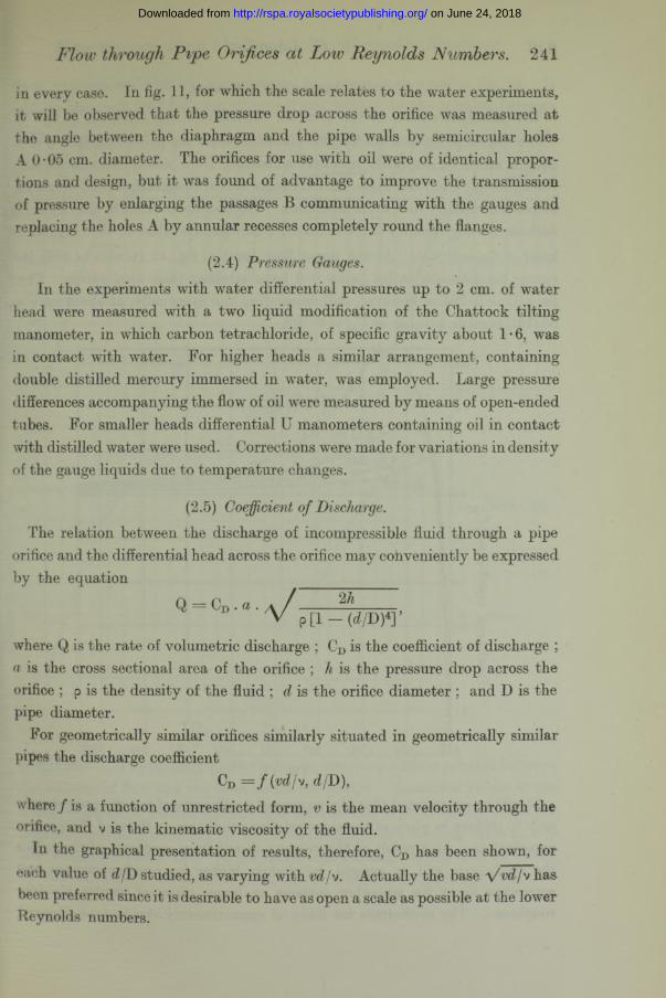
(2.3) Orifices.Four orifice diameter ratios (d/D
= 0 • 209, 0 • 401, 0 • 595 and 0 • 794) were studied, the diaphragms being shaped and mounted as shown in fig. 11. The thickness of the diaphragm was made approximately 1 /12 of the orifice diameter
on June 24, 2018http://rspa.royalsocietypublishing.org/Downloaded from
Flow through P ipe Orifices at Low Reynolds Numbers. 241
in every case. In fig. 11, for which the scale relates to the water experiments, it will be observed that the pressure drop across the orifice was measured at the angle between the diaphragm and the pipe walls by semicircular holes A 0-05 cm. diameter. The orifices for use with oil were of identical proportions and design, but it was found of advantage to improve the transmission of pressure by enlarging the passages B communicating with the gauges and replacing the holes A by annular recesses completely round the flanges.
(2.4) Pressure Gauges.In the experiments with water differential pressures up to 2 cm. of water
head were measured with a two liquid modification of the Chattock tilting manometer, in which, carbon tetrachloride, of specific gravity about 1 • 6, was in contact with water. For higher heads a similar arrangement, containing double distilled mercury immersed in water, w'as employed. Large pressure differences accompanying the flow of oil were measured by means of open-ended tubes. For smaller heads differential U manometers containing oil in contact with distilled water were used. Corrections were made for variations in density of the gauge liquids due to temperature changes.
(2.5) Coefficient of Discharge.The relation between the discharge of incompressible fluid through a pipe
orifice and the differential head across the orifice may conveniently be expressed by the equation
Q = CD . a t / 2hV p [ l - ( d /D ) * ] ’
where Q is the rate of volumetric discharge ; CD is the coefficient of discharge ; a is the cross sectional area of the orifice ; h is the pressure drop across the orifice ; p is the density of the fluid ; d is the orifice diameter ; and D is the pipe diameter.
For geometrically similar orifices similarly situated in geometrically similar pipes the discharge coefficient
CD = / (vd/v, df.D),where f is a function of unrestricted form, is the mean velocity through the orifice, and v is the kinematic viscosity of the fluid.
In the graphical presentation of results, therefore, CD has been shown, for each value of d/D studied, as varying with vd/v. Actually the base \ /vdjv has been preferred since it is desirable to have as open a scale as possible at the lower Reynolds numbers.
on June 24, 2018http://rspa.royalsocietypublishing.org/Downloaded from

242 F. C. Johansen.
(2.6) Numerical Coefficients.
The principal results of the pressure experiments are collected in fig. 12 where discharge coefficients for four diameter ratios are plotted against yW /v over a range of Reynolds numbers extending from nearly zero to 25,000. Rising steeply from the origin, the curves are at first straight, but bend over with increasing rapidity to reach a maximum. Beyond the maximum they descend with decreasing rapidity and eventually reach steady values in the neighbourhood of CD = 0-615. At the upper flow limit of fig. 12 (V vd/v — 160) the eurves for diameter ratios below 0-6 have attained their final values. That for d/D = 0-794 is, however, still descending and eventually, at about = 50,000, reaches a value of CD — 0-608.
-§ = 0-794
C 05
■ £ 0-2
F ig . 12.
I t will be appreciated that the numerical coefficients of fig. 12 apply strictly only to orifices in pipes of the same relative roughness as those of the present experiments. As a result of the velocity distribution upstream of the orifice the coefficients will, in general, be slightly higher for rougher surfaces and somewhat lower for smoother surfaces or larger pipes of similar absolute roughness. The coefficients for flows of approximately steady type, derived
on June 24, 2018http://rspa.royalsocietypublishing.org/Downloaded from

;har
ge C
oeff
icie
nt
C0
Dis
char
ge C
oeff
icie
nt C
q-
Flow through Pipe Orifices at Low Reynolds Numbers. 243
from experiments with, oil, are replotted to a more open scale in fig. 13. It will be observed that between vd/v = 0 and vdfv = 10 the relation between
0 8
0-7
0-6
05
04
0-3
0-2
01
0
0-8
0-7
0*6
0-5
0-4
0*3
0-205 oi
i l lvv
/
/
/
f
i/
/
jf
/
1_ d 1 0-2:091--1D G O -
/
1f
i
| /Jf
d '- 0 4 101c3
i
/
1i
f
</ *
/1
f
/0 1 2 3 4 5 6 7 0 1 2 3 4 5 6 7 8 9 10 II 12 0 1 2 3 4 5 6 7 8 9 10 II
-A- C astor Oil
-O- Lubricating Oil
-a- Water
0 1 2 3 4 5 6 7 8 9 1 0 II 12 13 14 0 1 2 3 4 5 6 7 8 9 1 0
J v d / v F ig. 13.
Vwlfi and CD is apparently perfectly linear, implying a linear relation between the velocity of flow and the head across the orifice. Numerical values of the slopes, CjVvd/v,plotted against djD for the four sizes of orifice originallyselected revealed a tendency for the slope to approach a limiting value as dfD was reduced towards zero. A few additional readings, taken with an orifice of diameter ratio O’09, and shown in fig. 13, served to confirm this view.
on June 24, 2018http://rspa.royalsocietypublishing.org/Downloaded from

244 F. C. Johansen.
(2.7) Comparison of Visual and Pressure Experiments.
The principal features of the discharge coefficient curves of figs. 12 and 13 may be related, with some degree of certainty, to corresponding types of flow pattern through and beyond the orifice, as obser ved in the visual experiments of Part I. Thus, the upper limit of steady flow, as revealed by the extent of the straight portions of the curves of fig. 13, occurs near = 10 for all the orifice diameter ratios, and may be compared with the same value of Reynolds number referred to in § (1.2) as appropriate to the observed steady flow, symmetrical about the plane of the orifice, for a diameter ratio 0 • 5. Departure from the linear relationship between pressure and velocity is definitely established, according to fig. 13, at vd/v = 30, and this Reynolds number is applicable to the pattern of fig. 3 in which the discharge from the orifice takes the form of a rapidly divergent jet. The development of the jet, in fig. 4, corresponds to the curvature of the CD curve as shown in fig. 13, between vdjv = 25 and 100. For the condition of fig. 5 (vd/v = 150) prior to the appearance of periodic flow, the CD curve is almost horizontal and approaching its maximum value. Corresponding to fig. 6, in the region of 250 where slight vorticity isapparent, the discharge coefficient is about at its maximum; whilst at vd/v — 600, in fig. 7, where vorticity is definitely established the discharge coefficient, according to fig. 12, has passed its maximum value and is diminishing in value. The relatively great length of the jet downstream of the orifice, which is a feature common to the flow patterns of figs. 5, 6 and 7, suggests a condition of minimum resistance to flow beyond the orifice ; and it is of interest to observe that over the corresponding range of Reynolds number (150 to 600) the discharge coefficient for d/D = 0*5 has an approximately constant, maximum value. The vortex train flow pattern of fig. 8, in which the turbulence is incomplete since it does not extend to the central filaments of the orifice jet, is typical (at vd/v — 1000) of the descending portions of the curves of fig. 13 during the transition from maximum to constant CD.
Finally, at Reynolds numbers above 2,000, fig. 9 shows the typical flow pattern, characterised by almost complete turbulence and subject to inappreciable modification as the rate of flow is increased. Reference to fig. 12 shows that for similar discharges, CD (for d/D =0*5) tends to a constant value, such uniformity being associated with the advent and persistence of complete turbulence.
One further comparison remains to be drawn. I t w7as noted, in the description of the visual experiments in § (1.2), that the transition from steady to
on June 24, 2018http://rspa.royalsocietypublishing.org/Downloaded from

turbulent flow was similar for different orifice dianfeter ratios, but that the specific stages were observed to occur, with large diameter ratios, at somewhat higher Reynolds numbers than was the case with small ratios. This phenomenon is very clearly exhibited by the discharge coefficient curves. Thus, in fig. 13, the slope of the straight portions of the CD vs V vd/v curves decreases progressively as d/D increases. Similarly, in fig. 12, the attainment both of a maximum discharge coefficient, and of completely turbulent conditions accompanied by a constant discharge coefficient, may be observed to occur at progressively larger Reynolds numbers as the orifice diameter ratio is increased.
Acknowledgment is very gladly made to Messrs. Stockwell and Cor die, of the Physics Department, National Physical Laboratory, for the photographs of figs. 2 to 9 ; and to Messrs. Linden and Gillman, of the Aerodynamics Department, National Physical Laboratory, for the construction of the apparatus.
Summary.
The flow of water through a sharp-edged circular orifice mounted concentrically in a glass pipe has been studied, by the introduction of colour, over a range of low Reynolds numbers. The transition from steady to turbulent flow is gradual, and photographs are reproduced illustrating the various stages in the flow pattern.
Over a similar range of Reynolds numbers, by the use of oils of high viscosity, the relation between the volumetric discharge and the pressure drop across a sharp-edged orifice has been determined. I t is possible to relate many of the pressure characteristics to features of the flow pattern observed visually.
Flow through Pipe Orifices at Low Reynolds Numbers. 245 on June 24, 2018http://rspa.royalsocietypublishing.org/Downloaded from