flow regimes of particle settling in suspensions and non ... · drilling fluid (“mud”) ... to...
TRANSCRIPT
ANNUAL TRANSACTIONS OF THE NORDIC RHEOLOGY SOCIETY, VOL. 22, 2014
ABSTRACT Settling velocities of cuttings particles in
drilling fluid (“mud”) is one of the most important parameters for the efficiency of drilling long deviated wells. Numerical simulators have been developed worldwide to assist the optimization of cuttings transport. Models for particle settling velocities to enter these simulators are based on experimental conditions which not always reflect the situation they are used for in industrial processes.
Effects which modify and disturb settling velocities are drillstring movement, liquid convection and turbulence, cuttings particles size and shape, particle-particle interaction, and - most important - the drilling mud rheology and composition. This also includes oil-water dispersions and also free gas in the mud.
The experimental work of this paper has been developed to a large extent in connection with a Master thesis1 at the University of Stavanger. The motivation for the study was to determine the impact of flow regimes on settling modes and falling velocities.
In the present paper the main focus is on theoretical aspects and analysis methods involved. More results from the laboratory tests will be described in the presentation for the NRS 2014 Conference.
Laboratory experiments using high speed video recordings were used to reveal
some of these effects. As might be expected, the settling flow regimes and are quite different for Newtonian versus non-Newtonian liquids. Finally, we describe image analysis assisted determination of fall speeds.
INTRODUCTION Cuttings transportation under real
drilling operations naturally involves a whole spectrum of particle sizes. In this project both mono-dispersed and multiple size slurries were tested. If the liquid flows turbulent in itself it is a challenge to calculate frictional drag on particles, since the drag coefficient is based on the particle’s Reynolds number. For multiphase flow this is even more complex, since droplets’ interfacial deformation and the fluid flow is strongly interconnected.
Drilling companies report substantially improved hole cleaning efficiency with oil-water mud, and researchers2 also on invert oil-water mud using nano-particles for emulsion stabilization. Furthermore, it has been suggested e.g. for underbalanced drilling to utilize gas bubbles to modify the flow pattern and create gas bubble assisted lift of cuttings particles. Some preliminary results of impact on cuttings settling from such multiphase flow situations will be addressed in this work.
Flow Regimes of Particle Settling in Suspensions and Non-Newtonian Fluids
with Relevance to Cuttings Transport during Drilling
Rune W. Time and A.H. Rabenjafimanantsoa
University of Stavanger, Norway
115

THEORY Modelling of particle settling has been
carried out analytically since the 18th century for single particles in Newtonian fluids, and later both experimentally and analytical-numerical for clouds of particles and for non-Newtonian liquids. Single particle settling in Newtonian fluids
The earliest models for particles falling in fluids are dating back to Stokes3,4 (1851) for a pendulum and Basset5 (1889) for a falling sphere, arriving at the well-known equation for the drag force D under laminar creeping conditions, often referred to as Stokes law; D 6 RUf SP (1) Frequently it is expressed using the drag coefficient, CD,
2 21D 2D C R ( U )f S U (2)
where D24CRe
, Uf is the free stream fluid
velocity, U dRe f Q
is the Reynolds
number, with d being the particle diameter and Q the kinematic viscosity. Remarkably simple still, Stokes law has been important for 3 Nobel Prizes6, e.g. the famous Millikan oil drop7 experiment to determine the electron charge. More information can be linked from the Stokes biography8. Flow regimes – a brief classification
In this work the term “particle settling flow regimes” refers to both single phase and multiphase fluids. For single phase fluids there is also a marked difference in particle settling dynamics between Newtonian and non-Newtonian fluids. For multiphase systems there will also be substantial variation, depending on the degree of mixing of the immiscible phases (oil, water or polymer and gas) plus particles. Finally, for all the above cases single particles fall in a different way from clouds or assemblies of particles28,29,30,31.
Multiple particle (cloud) flow regimes are often based on the particle volumetric fraction D as either dilute (D�< 0.01) or dense (D > 0.01). Dense is further divided (Crowe9) into collision dominated (D�< 0.1) or contact dominated (D > 0.1).
For Newtonian fluids a particle starting with an initial velocity v different from the surrounding fluid velocity u, will be “relaxed” within a characteristic response time9
2d
VC
D18U
W P
(3)
where dU is the particle density, D the diameter, and CP is the surrounding fluid viscosity. The governing equation of motion for the relaxation disregarding gravity is
V
dv 1 (u v)dt
�W
(4)
with the solution ; Vt /v u(1 e )� W � (5)
The response time ranges from milliseconds for micron sized particles, to a second or more for particles in the cm range. This relation is still associated with laminar flow, so if the flow regime in the fluid itself is turbulent the response time will normally decrease, while on the other hand the particle velocity fluctuations increase.
In presence of gravity the equation of motion becomes
V P
dv f (u v) (1 )gdt
U � � �W U
(6)
Where f is friction factor DC 24fRe�
.
For complex fluids and particle systems it could be feasible to extend this to a “Langevin equation” approach10 ;
V P
dv 1 (u v) (1 )g F '(t)dt
U � � � �W U
(7)
where F’(t) describes the fluctuations caused by macroscopic collisions. This has been used in a published CFD model11.
116
Experiments were done to test the accuracy of the relaxation equation for large particles, as described in the sections describing experiments and analysis. During fall the flow around larger particles undergo a transition from laminar to turbulent flow.
While calculation of drag coefficient is fairly straightforward, it is more intricate to calculate free fall velocities since the unknown velocity is implicit both in the Reynolds number and in the drag coefficient. This can be overcome12 by using the Archimedes number
32 P
D 2
g ( )d4Ar C Re3§ ·U U �U
� ¨ ¸P© ¹ (8)
Here PU , U and P are particle density, and liquid density and viscosity respectively.
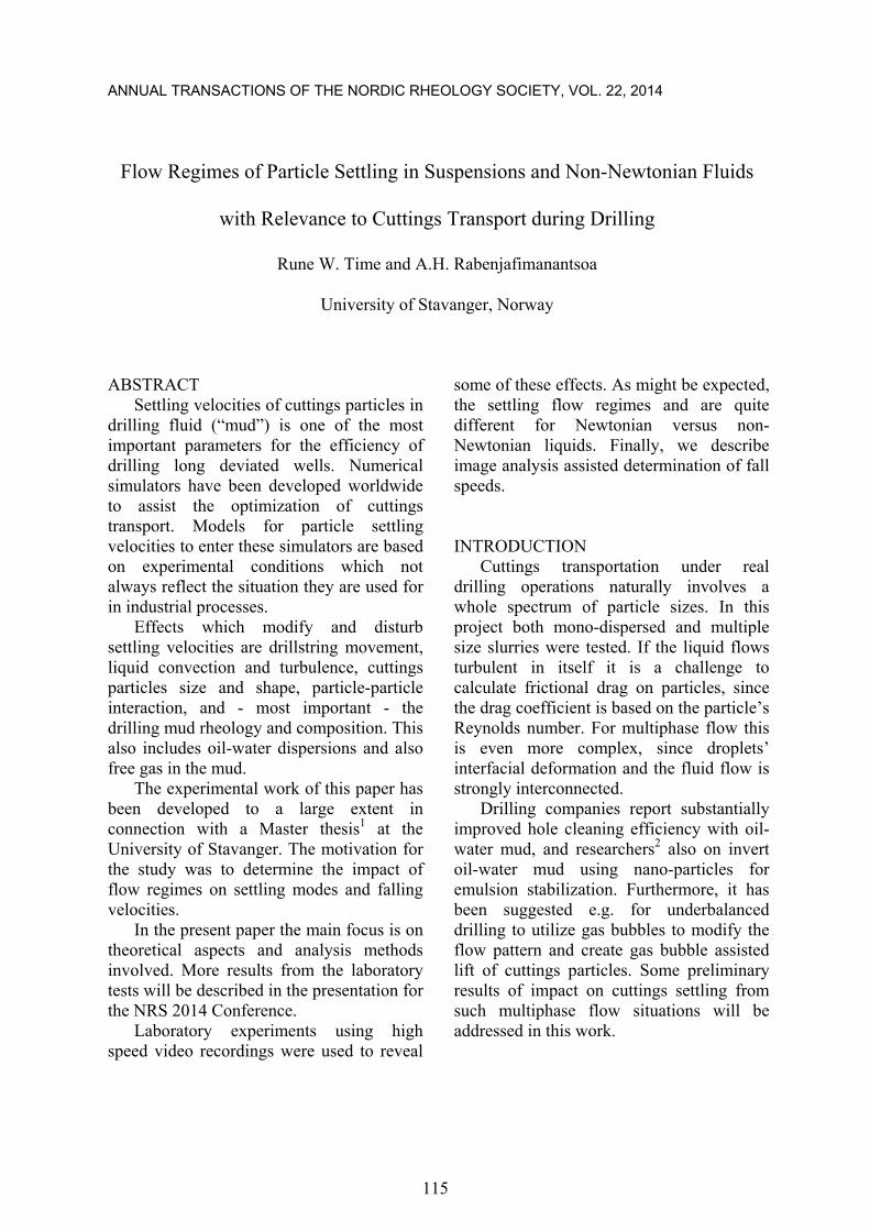
A range of different drag coefficients have been developed. One such correlation to cover a wide range of Reynolds numbers is given by Morrison13, and data fitted to seven orders of magnitude. It is shown inserted in Fig. 1 below and was used for equation 6, in the Matlab program which produced Fig. 8.
Figure 1. Data Correlation for Drag Coefficient
for Sphere (all Reynolds numbers)13.
A fairly good and nicely illustrated description of such a transition regime is given in an MIT OpenCourse book14 as follows;
“… flow separation can be said to begin at a Reynolds number of about 24. The point of separation is at first close to the rear of the sphere, and separation results in the formation of a ring eddy attached to the rear surface of the sphere. Flow within the eddy is at first quite regular and predictable, thus not turbulent, but, as Re increases, the point of separation moves to the side of the sphere, and the ring eddy is drawn out in the downstream direction and begins to oscillate and become unstable. At Re values of several hundred, the ring eddy is cyclically shed from behind the sphere to drift downstream and decay as another (ring) forms. Also in this range of Re, turbulence begins to develop in the wake of the sphere. At first turbulence develops mainly in the thin zone of strong shearing produced by flow separation and then spreads out downstream, but as Re reaches values of a few thousand the entire wake is filled with a mass of turbulent eddies ..”
This “ring-wave” process has been visualised in another paper in these proceedings15 using an immiscible phase (oil or air) clinging to the particles. Particle settling in Non-Newtonian liquids
Particle settling in polymeric liquids is more complex than in the Newtonian case. Chhabra12 gives a good overview of studies of sphere motion in shear-thinning liquids. An alternative to Stokes drag law is given as
DF 3 dU Yf SP � (9) where the correction factor Y is given as
D PL
2 n n
PL
C ReY , 24
V dand Rem
�
�
U
(10)
Y is then modelled in various ways, e.g like Kawase12,16
2((3n 3) / 2) 7n 4n 26Y 3
5n(n 2)� ½� � �
® ¾�¯ ¿ (11)
This analytical model is valid for RePL < 20, while Ceylan17 presented a correlation valid for Re<100. Matijašiü and Glasnoviü18
117

modelled drag coefficient up to 1000. Kelessidis and Mpandelis19 presented an explicit model for terminal velocity of pseudoplastic liquids beyond Re > 1000. Slurry transport in single phase fluids
As described in the Theory section, the behaviour of multiple particle flows can be described in terms of the volumetric fraction of particles D as either dilute or dense.
However, this classification does not fully incorporate the dynamics of particles and fluid. A more complete description is given in terms of the ratio of the particle response time, VW (Eq. 3) to the mean time
CW between particle collisions. So, if V
C
1W�
W
the system is said to be dilute. And else it is dense. Contact flow is typical e.g. for strongly sheared sand bed structures or fluidised beds. In Fig. 2 is shown four phases in a pipe flow when the flow is suddenly stopped. The particles quickly form a bed while smaller particles are gradually settling.
Collision regimes
Clouds of particles in Newtonian systems are fairly well described by a drift-flux model, where the effective settling velocity v can be expressed by the unhindered “terminal” settling velocity Uf multiplied with a factor depending on the local (volumetric) fraction D of particles. The exponent n depends on the system properties and flow regime.
12v (1 ) , 2nU nDf � � d d (12)
Figure 2. Multiphase flow of air-oil-water and
sand particles forming a bed in an 8 cm i.d. diameter pipe. The flow has just stopped and the
interface layers become stratified. Maximum grain size is 1mm.
The theory of colliding particles in non-
Newtonian liquids is more complex, and simple correlations are not available. Numerical simulations on simple systems have been published20. EXPERIMENTS Experimental setup
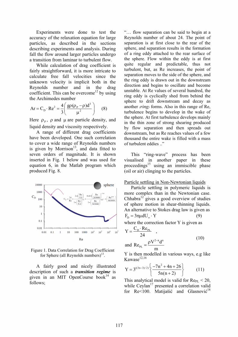
The experiments were recorded by means of high speed cameras, see Fig. 3 and 4. For the highest fall velocities e.g. with steel balls a high speed camera was used (SpeedCam MiniVis e2) that records up to 2500 fps at full resolution 512x512 pixels. It can record up to 120.000 fps at reduced resolution. The camera has onboard memory for 8223 full frames at full resolution. Images are downloaded to computer via a GigaBit Ethernet cable by means a communication program (“MotionBlitz”, by Mikrotron). In other cases with slower fall speed a 16MPixel Samsung EK-GC100 was used. In slow motion mode it can record 120 fps at resolution 768x512pixels.
118
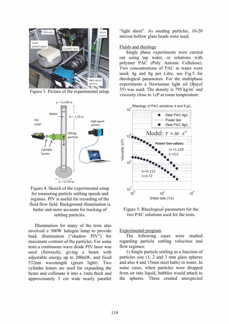
Figure 3. Picture of the experimental setup.
Figure 4. Sketch of the experimental setup for measuring particle settling speeds and regimes. PIV is useful for recording of the
fluid flow field. Background illumination is better and more accurate for tracking of
settling particles.
Illumination for many of the tests also involved a 500W halogen lamp to provide back illumination (“shadow PIV”) for maximum contrast of the particles. For some tests a continuous wave diode PIV laser was used (Suwtech), giving a beam with adjustable energy up to 200mW, and fixed 532nm wavelength (green light). Two cylinder lenses are used for expanding the beam and collimate it into a 1mm thick and approximately 5 cm wide nearly parallel
“light sheet”. As seeding particles, 10-20 micron hollow glass beads were used. Fluids and rheology
Single phase experiments were carried out using tap water, or solutions with polymer PAC (Poly Anionic Cellulose). Two concentrations of PAC in water were used; 4g and 8g per Litre, see Fig.5 for rheological parameters. For the multiphase experiments a Newtonian light oil (Bayol 35) was used. The density is 795 kg/m3 and viscosity close to 1cP at room temperature.
Figure 5. Rheological parameters for the two PAC solutions used for the tests.
Experimental program
The following cases were studied regarding particle settling velocities and flow regimes:
1) Single particle settling as a function of particles size (1, 2 and 3 mm glass spheres and also 4 and 15mm steel balls) in water. In some cases, when particles were dropped from air into liquid, bubbles would attach to the spheres. These created unexpected
119

opportunities to study combined effects of buoyancy and drag reduction.
2) Single particle settling in non-Newtonian liquid, with 4g/L and 8g/L of PAC in water. Most experiments described here involve 4g/L.
3) Ensembles of particles in single phase tap water or in PAC solutions. In some cases gas bubbles attach, and were clearly visible in the high speed images. This is shown in Fig. 10b.
4) Ensembles of particles in a multiphase oil - PAC - air system. Both stratified and stirred mixed were used, to see effect of liquid turbulence.
A total of 35 experiments were carried out backed up with high speed cameras recordings. Subsequent offline analysis allows monitoring of fluid dynamic details, as well as accurate calculation of particle fall speeds. Only a few experiments and effects could be discussed in this paper – due to space limitations. ANALYSIS AND DISCUSSION Analysis of the high speed images as in Fig. 6 can be a tedious process in view of the huge amount of pictures generated.
Figure 6. Steel ball 4 mm just after release from tube entering into the PIV laser sheet.
Seeding particles clearly visible.
So, it was desirable to develop a method to calculate settling speed in an automated way. It was attempted to calculate the particle position by a fully automated image analysis, however in many cases the optical conditions are not optimal for automated detection. Therefore, a “hybrid” manual and automated algorithm was used. The program calculated the light intensity on pixel basis along a chosen vertical line which the particle follows, and plotted it as a function of depth as shown Fig. 7. This made it easier for manual inspection to find the position of appropriate reflected light from the particles.
Figure 7. Matlab assisted tracking of the ball
position. a) left, shows the original image b)right shows light intensity along the
vertical line and the peak associated with reflexes from the ball.
Figure 8. Calculation of particle fall speed
based on images as in Fig 6. A Matlab program was used to show the position of the sphere and store positions (in Excel).
0 0.01 0.02 0.03 0.04 0.05 0.06 0.07 0.08 0.09 0.1-1.4
-1.2
-1
-0.8
-0.6
-0.4
-0.2
0Vertical fall speed
Time (s)
Spe
ed m
/s
TheoryRaw dataAveraged velocityError bars
120

Based on the calculated positions for the particles the velocity could be determined. To compare the velocities from experiments, other programs were written to calculate both terminal velocities as well as particle speed as a function of time for given fluid and particle data. Single particle flow in liquid
Both steel balls and glass beads were tested with single phase liquids for comparison with published models for drag coefficients and also for comparison of experiments with other fluid conditions.
Ensembles of falling particles
As explained in the theory section an ensemble of particles the settling speed is reduced compared to the single unhindered particle case, and can be described with drift-flux theory
However, as can be seen from Fig. 9 the dynamics of the flow is widely different in a Newtonian versus non-Newtonian liquid. With PAC (8g/L) the particles in the outer part of the cluster moved upwards during the fall as if forming an outer protecting skin. The outer bubbles were eventually released from the group at the rear as in Fig. 9 (right). The same behaviour was seen also with 4g/L of PAC, but with less redistribution for smaller particles.
Figure 9. Ensembles of 3mm glass spheres
falling spread in water (left) versus (right) as agglomerates in PAC (8g/L).
Particles falling with air bubbles or oil drops attached
If particles are dropped from air instead of carefully released in the liquid, the impact may entrain air and cause bubbles to adhere to the back of the particles. Or, as in the case of oil + PAC systems also oil could attach to the particle when they enter into the PAC phase. See Fig. 10. It was expected that the attachments would modify the settling speed. Since both air and oil is lighter than the water (PAC) phase one might expect the particles to slow down due to buoyancy. Instead the fall speed increased with 5-10 %. In view of the buoyancy, this means that the drag reduction effect must be even larger.
Figure 10. Left) Oil droplets cling to 3mm glass spheres falling in PAC (4g/L) after crossing the
oil-PAC interface. Right) 4mm steel spheres falling in water with air bubbles attached.
Surface tension effect of gas bubble settling in multiphase
In the presence of a substantial fraction of gas (air) the interfacial tension between liquid and gas is so high that bubbles may become nearly foam like with lamellae27. In such situation particles cannot penetrate unless the density and the gravitational force exceed the capillary forces in the lamellae. In Fig. 11 is shown a heavy layer of white and dark sand particles on top of water, separated by a layer of air bubbles. The dark particles are approximately 100-200 micron, the light particles 10 - 20 micron. The small white particles easily sieve between the bubbles, while release and fall of large particles takes place in bursts only when air bubbles redistribute and makes larger openings.
121

Figure 11. A layer of sand on top of water separated by a layer of air bubbles, sieving down
through a bubble layer. Inserted image shows mm/cm scale.
Particle stabilization of oil-water emulsions
Water-oil dispersions become stabilized if small particles are present. In Fig. 12 is shown a system of oil and water mixed with sand particles (river sand), sieved to less than 1mm. Initial mixing was achieved by shaking inside a closed cylinder to create a light dispersion. Then the mixture was allowed to stand for several hours.
a) b)
c) Figure 12. a. Sand grains remaining in oil-water dispersion at different instants t after turbulent mixing. Within a minute the largest particles
settle, while small particles less than 100 micron remain in the water lamellae between oil
droplets, and seem to stabilize the dispersion. Scale is 1mm per tick. The darkest particles are less than 100 micron. a) t=0 b) t=2hrs 6min c)
t=5hrs 45min
This phenomenon” is often referred to as “Pickering stabilization” 21,22 small particles are trapped in the water lamellae between oil droplet due to electric and viscous forces.
For multiphase systems only few papers have been published on transportation of particles through lamellae23,24. Interfacial tension effects as these become even more important in the case of colloidal fluids where particle coating and high viscosity at low shear rates are present, as in lamellae films. SUMMARY
For drilling operations cuttings particles most often appear as very dense slurries. In addition particles are generally transported in inclined pipes involving both a longitudinal and transversal direction of liquid and particles. Also with the broad particle size range, cutting particles in a non-Newtonian liquid may be expected to show up with most of the effects discussed in this paper.
Given the many parameters that govern particle settling in most real industrial applications like well drilling, it is not straightforward to establish anything like a flow regime map – as e.g for gas-liquid flow in pipelines. Even for simplified laboratory tests it turns out that fluid rheology and particle concentration and also initial and boundary conditions are important. Also the settling regimes are different for single phase fluids and for multiphase flow. Therefore it is important to provide more experiments to reveal the how different conditions influence settling regimes.
Based on transparent model liquids, the use of high-speed video recording as in this work enables valuable insight into the basic regimes of particle settling. This also provides accurate calculation of settling speed, and large amounts of tests can efficiently be analysed with computer assisted image analysis.
For single phase flow the regimes are mainly connected to the rheological
122
properties of the liquid and the transition regimes for the boundary layer around the spheres. For multiphase flow the important phenomena are related to interfacial effects and wetting of the particles. ACKNOWLEDGMENTS
We are grateful to MSc student Maria Sletteng Johnsen for her valuable contributions to the experiments. High speed cameras and laser system were granted by the Norwegian Research Council.
REFERENCES 1. Sletteng Johnsen, M. (2014), "Particle Transport and Hole Cleaning in Wells During Drilling" MSc thesis, University of Stavanger. 2. Agarwal, S. et al. (2013),”Nanoparticle-stabilised invert emulsion drilling fluids for deep-hole drilling of oil and gas”, The Canadian Journal of Chemical Engineering, 91 (10) 1641–1649. Also; 2. Halliburton – Baroid: http://www.halliburton.com/en-US/ps/baroid/fluid-services/drilling-fluids-solutions/invert-emulsion-drilling-fluid-systems.page?node-id=hfyjrry0 3. Stokes, G. G. (1851), “On the effect of the internal friction of fluids on the motion of pendulums”, Trans. Cambr. Phil. Soc. 9. (Pt II), 8-106. http://www.nawcc-index.net/Articles/Stokes-InternalFriction.pdf 4. Feng and Joseph (1995), “The unsteady motion of solid bodies in creeping flows“, J. Fluid Mech., vol. 303, pp. 83-102. 5. Basset A, . B. 1888 “On the motion of a sphere in a viscous liquid”. Phil. Trans. R. Soc. Lond. A 179, 43-63. http://rsta.royalsocietypublishing.org/content/179/43.full.pdf 6 and 7. Wikipedia: http://en.wikipedia.org/wiki/Stokes'_law http://en.wikipedia.org/wiki/Oil_drop_experiment
8.http://wwwp.cord.edu/faculty/ulnessd/legacy/fall1998/sonja/stokes.htm 9. Crowe, C. et al. (1998), “Multiphase flows with Droplets and Particles”, CRC Press, 1998. 10. Reif, F. (1985), “Fundamentals of Statistical and thermal physics”, McGraw Hill. 11. Debhi, A., (2008), “Turbulent particle dispersion in arbitrary wall-bounded geometries: A coupled CFD-Langevin-equation based approach”, Int. J. of Multiphase Flow, 34 (2008) 819–828 12. Chhabra, R.P. (2007), “Bubbles, Drops and Particles in non-Newtonian Fluids, CRC Press, 2nd edition. 13. Morrison, F.A. (2013),”Data Correlation for Drag Coefficient for Sphere”, http://www.chem.mtu.edu/~fmorriso/DataCorrelationForSphereDrag2013.pdf 14. MIT, OpenCourse book: http://ocw.mit.edu/courses/earth-atmospheric-and-planetary-sciences/12-090-introduction-to-fluid-motions-sediment-transport-and-current-generated-sedimentary-structures-fall-2006/course-textbook/ch3.pdf 15. Rabenjafimanantsoa, A.H. and R.W. Time, R.W. (2014), “Fluid dynamics of film drainage around solid particles and spheres falling through a liquid-liquid interface”, Ann. Trans. Nordic Rheol Soc., Vol. 22, 16. Kawase,Y. and Moo-Young, M. (1986), “Approximate solutions for power-law fluid flow past a particle at low Reynolds numbers”, J. Non-Newt. Fluid Mech., 21, 167. 17. Ceylan et al (1999); “A theoretical model for estimation of drag force in the flow of non-Newtonian fluids around
123

spherical solid particles”, Powder Technol., 103, 286. 18. Matijašiü, G. and Glasnoviü, A. (2001), “Measurement and Evaluation of Drag Coefficient for Settling of Spherical Particles in Pseudoplastic Fluids”, Chem. Biochem. Eng. Q. 15 (1) 21–24. 19. Kelessidis, V.C. and Mpandelis, G. (2004), “An explicit equation for the terminal velocity of solid spheres falling in pseudoplastic liquids, Chem .Eng. Sci., 59, 21, 4437. 20. Tsao-Jen Lin (2009), “Mechanisms of in-line coalescence of two-unequal bubbles in a non-Newtonian fluid”, Chem. Eng. Journal, 155, 750–756. 21. Pickering, S.U. (1907), “Emulsions”, J. Chem. Soc. 91 22. Ramsden, W. (1903), “Separation of Solids in the Surface-layers of Solutions and 'Suspensions', Proc. R. Soc. London 72, 156. 23. Sullivan, A.P. and Kilpatrick, P. K. (2002), “The Effects of Inorganic Solid Particles on Water and Crude Oil Emulsion Stability”, Ind. Eng. Chem. Res., 41, 3389-3404. 24. Mohebali, G. et al (2007), “Stabilization of water/gas oil emulsions by desulfurizing cells of Gordonia alkanivorans RIPI90A”, Microbiology, 153, 1573–1581. 25. Potapova, E. (2011), “Adsorption of surfactants and polymers on iron oxides: implications for flotation and agglomeration of iron ore”, PhD Thesis Luleå, https://pure.ltu.se/portal/files/33719998/Elisaveta_Potapova.Komplett.pdf 27. Wikipedia; “Foam” http://en.wikipedia.org/wiki/Foam
28. Becker, L. E. et al (1993),” The unsteady motion of a sphere in viscoelastic fluid”, J. Rheol. , 38 (2) 29. S. Hasani, S. et al. (2011), “Irregular Motion of a Falling Spherical Object Through Non-Newtonian Fluid”, http://arxiv.org/ftp/arxiv/papers/1108/1108.3427.pdf 30. Kishore, N. et al. ( 2008), “Drag on Ensemble of Fluid Spheres Translating in a Power_Law Liquid at Moderate Reynolds Numbers”, Chem. Eng. J., 2008, vol. 139, p. 224. 31. Schlichting. H. (1954-1968), “Boundary Layer Theory”, McGrawHill.
124