flow rate indicator / totalizer - sechangdownload.sechang.com/pds/3000/3000_15159a.pdf · general...
TRANSCRIPT

Features• Displays instantaneous flow rate, total and
accumulated total.• Large 17mm (0.67") digit selection for flow rate
or total.• Selectable on-screen engineering units;
volumetric or mass.• Ability to process all types of flowmeter
signals.• Auto backup of settings and running totals.• Operational temperature -30°C up to +80°C
(-22°F up to 178°F).• Very compact design for panel mount,
wall mount or field mount applications.• Rugged aluminum field mount enclosure
IP67/NEMA4X.• Intrinsically Safe
II 1 GD EEx ia IIB/IIC T4 T100°C.• Analog and pulse signal outputs.• Full Modbus communication RS232/485/TTL.• Loop or battery powered, 8 - 24V AC/DC or
115 - 230V AC power supply.• Sensor supply 3.2 / 8.2 / 12 / 24V DC.
Signal output• (0)4 - 20mA / 0 - 10V DC according to flow rate.• Scaled pulse output according to accumulated
total.
Signal inputFlow• Reed-switch.• NAMUR.• NPN/PNP pulse.• Sine wave (coil).• Active pulse signals.
Applications• Liquid flow measurement where
re-transmission of the flow rate and/ortotalizer functions or serial communicationis required.D
ATA
SH
EE
TE
R1/
Rx5
10 F
LOW
RA
TE I
ND
ICA
TOR
/ T
OTA
LIZE
R
1
FLOW RATE INDICATOR / TOTALIZERWITH ANALOG AND PULSE SIGNAL OUTPUTS

General informationIntroductionThe 110 is the most popular model in our rangeof flow rate / totalizers, complete with pulseand analog output signals. Even demandingapplications are catered for with our base unitconfiguration. A wide selection of optionsfurther enhance this models capabilities, inclu-ding Intrinsic Safety & Modbus communication.
DisplayThe display has large 17mm (0.67”) and 8mm(0.31”) digits which can be set to show flow rateand totals. On-screen engineering units areeasily configured from a comprehensiveselection. The accumulated total can register upto 11 digits and is backed-up in EEPROMmemory every minute.
ConfigurationAll configuration settings are accessed via asimple operator menu which can be pass-codeprotected. Each setting is clearly indicated withan alphanumerical description, thereforeavoiding confusing abbreviations and bafflingcodes. Once familiar with one F-series product,you will be able to program all models in theseries without a manual. All settings are safelystored in EEPROM memory in the event ofsudden power failure.
Analog output signalThe flow rate is re-transmitted with the (0)4 - 20mA or 0 - 10V DC output signal. The output signal is updated ten times persecond with a filter function being available tosmoothen out the signal if desired. The output value is user defined in relation tothe flow rate, e.g. 4mA equals to 15L/Hr and20mA equals to 2000L/Hr. The output signal canbe passive, active or isolated where the passiveoutput type will loop power the 110 as well.
Pulse outputThe scaleable pulse output, reflects the count onthe accumulated display. The pulse length isuser defined from 0.008 second up to 2 seconds.The maximum output frequency is 64Hz. The output signal can be a passive NPN, activePNP or an isolated electro-mechanical relay.
Signal inputThe 110 will accept most pulse and analog inputsignals for flow or mass flow measurement. Theinput signal type can be selected by the user inthe configuration menu without having toadjust any sensitive mechanical dip-switches orjumpers. The analog input versions are evenavailable as 4-20mA input loop powered displays.
CommunicationAll process data and settings can be read andmodified manually or through the Modbuscommunication link (RS232 / RS485). Full Modbus functionality remains available forthe Intrinsically Safe version (TTL).
Hazardous areasFor hazardous area applications, this model hasbeen ATEX certified Intrinsically Safe II 1GD EEx ia IIB / IIC T4 T100°C with an allowedoperational temperature of -30°C to +70°C (-22°F to +158°F).
EnclosuresThere are three types of enclosures available: The GA Round Charcoal (Macnaught) versionand the GC Round Red version areavailable with 3 x 1/2”NPT cable gland entrythread or 2xM16 & 1xM20 cable gland entrythread. The third enclosure is the GB enclosure which is available in GRP (GlassfiberReinforced Polyamide) or Aluminum. For thecable gland entry available see page 6.
Overview application 110
Pulse output Analog output Communication link
external reset button
Flowmeterinput
1102
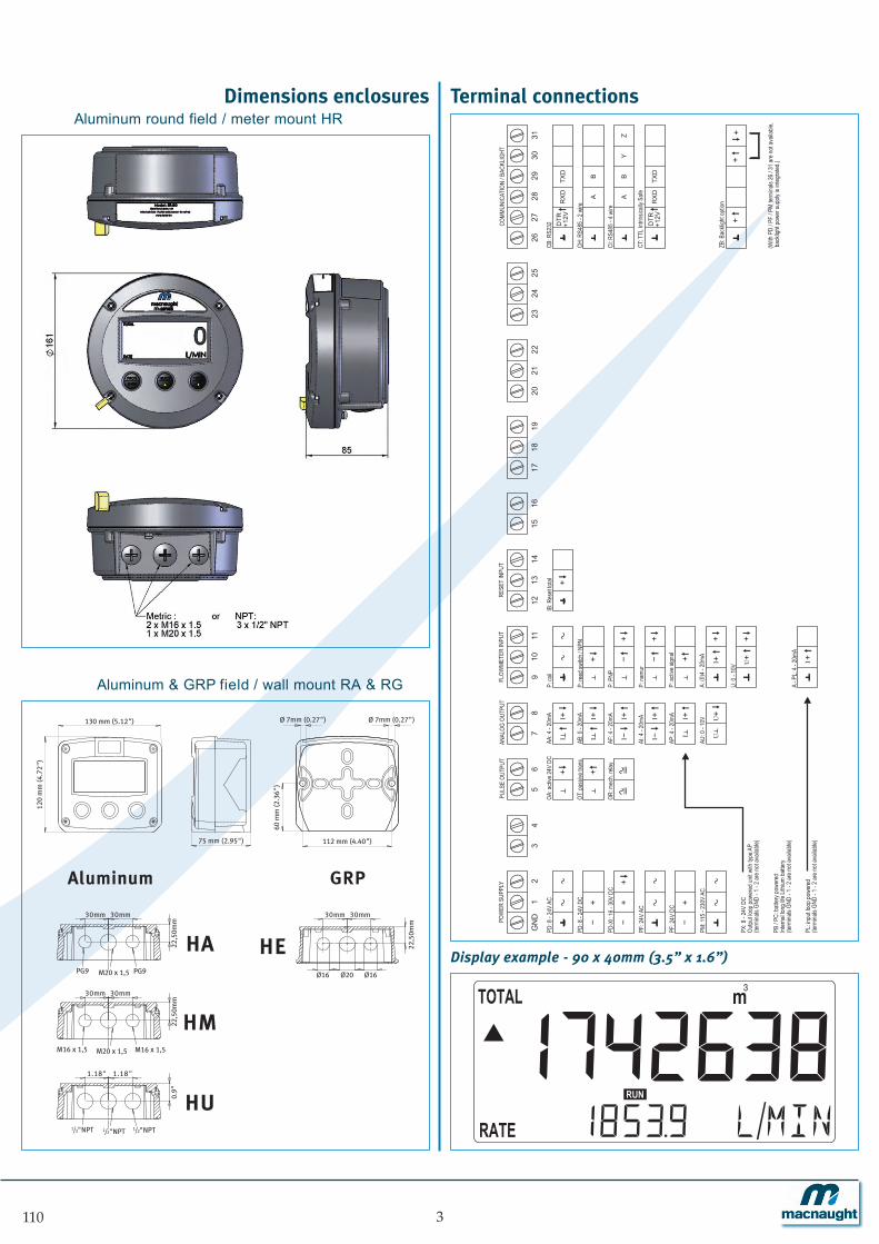
Dimensions enclosuresAluminum round field / meter mount HR
Aluminum & GRP field / wall mount RA & RG
Terminal connections
Display example - 90 x 40mm (3.5” x 1.6”)
CB: R
S232
CH: R
S485
- 2 w
ire
AB
YZ
RX
DT
XD
CT: T
TL In
trinsic
ally S
afe
P: re
ed sw
itch /
NPN
P: co
il
P: na
mur
P: P
NP
A: (0
)4 -
20mA
P: ac
tive s
ignal
U: 0
- 10V
-
+
==
56
PULS
E OU
TPUT
12
POW
ER S
UPPL
Y
GN
D
-+
PD: 8
- 24
V AC
PD: 8
- 24
V DC
-+
PF: 2
4V A
C
PM: 1
15 -
230V
AC
PF: 2
4V D
C
PD-X
I: 16 -
30V
DC
+-
+
OT: p
assiv
e tra
ns.
OT: p
assiv
e tra
ns.
OA: a
ctive
24V
DCOA
: acti
ve 24
V DC
OR: m
ech.
relay
OR: m
ech.
relay
+
==
34
PULS
E OU
TPUT
10
11
FLOW
METE
R IN
PUT
9
+
+ -+
+
+ +
AP: 4
- 20
mA
AA: 4
- 20
mA
AF: 4
- 20
mA
AU: 0
- 10
V
AI: 4
- 20
mA
AB: 0
- 20
mA
78
ANAL
OG O
UTPU
T
+II-
+I +U
I U
+II
+II-
+II
OT: p
assiv
e tra
ns.
OA: a
ctive
24V
DC
OR: m
ech.
relay
+
+
+I +U
A - P
L: 4 -
20mA +I
IB: R
eset
total13
14
RESE
T IN
PUT
12
18
19
17
15
16
27
28
COMM
UNIC
ATIO
N / B
ACKL
IGHT
26
23
24
25
21
22
20
29
30
31
DT
R+
12V
CI: R
S485
- 4 w
ire
AB
RX
DT
XD
DT
R+
12V
ZB: B
ackli
ght o
ption
+
++
+
PX: 8
- 24
V DC
Outpu
t loop
powe
red u
nit w
ith ty
pe A
P(te
rmina
ls GN
D - 1
- 2 a
re no
t ava
ilable
)
PB / P
C: ba
ttery
powe
red
Inter
nal lo
ng lif
e Lith
ium ba
ttery
(term
inals
GND
- 1 -
2 are
not a
vaila
ble)
PL: in
put lo
op po
were
d(te
rmina
ls GN
D - 1
- 2 a
re no
t ava
ilable
)
(With
PD
/PF
/ PM
termi
nals
26 / 3
1 are
not a
vaila
ble,
back
light
powe
r sup
ply is
integ
rated
.)
110 3
75 mm (2.95")
130 mm (5.12")
112 mm (4.40")
60 m
m (2
.36"
)
120
mm
(4.7
2")
M20 x 1,5PG9 PG9
30mm 30mm
22,5
0mm
M20 x 1,5M16 x 1,5 M16 x 1,5
30mm 30mm
22,5
0mm
1/2"NPT1/2"NPT 1/2"NPT
1.18" 1.18"
0.9"
HA
HM
HE
HU
22,5
0mm
30mm 30mm
Ø16 Ø16Ø20
Aluminum GRP
Ø 7mm (0.27") Ø 7mm (0.27")

Typical wiring diagram 110-P-(AP)-CH-IB-OT-PB Typical wiring diagram 110-P-AP-CH-IB-OT-PX
910
11
12
65
13
Common ground
Signal
Supply *
Common ground
TERMINAL CONNECTORSF100-series
78
Common ground
Flowmeter input type: Ppulse
Circu
it dep
ends
on
type o
f sign
al
28
27
26
29
8 - 30V DC
+
-
A
Common ground
B
Common ground
+ 3.2Vlow-pass
filter
1M
* Supply voltage: 1.2 / 3.2V DC to sensor
123456e.g. counter
Status input type IB:reset total
e.g. indicator
Analog output type AP: passive 4 - 20mA (loop powered)
Modbus communication type CH: RS485 - 2 wire
Pulse output type OT:
passive transistor
OUTPUT LOOP POWERED9
10
11
Common ground
Common ground
Signal
Supply *
TERMINAL CONNECTORSF100-series
78
Common ground
Circu
it dep
ends
on
type o
f sign
al
28
26
29
A
Common ground
B
* Supply voltage: 1.2 / 3.2V DC to sensor
Flowmeter input type: Ppulse
Modbus communication type CH: RS485 - 2 wire
Analog output type AP:Passive 4 - 20mA
(not used in this example)
BATTERY POWERED
Status input type IB:reset total
12
13
+ 3.2Vlow-pass
filter
1M
65Common ground
Please note: AP may be used in combination with the
battery!
AP will power the unit (output loop powered);
the battery will be disabled automatically untill power
is disconnected).
Pulse output type OT: passive transistor
(not used in this example)
1104

Typical wiring diagram 110-A-AA-CB-IB-OA-PD Typical wiring diagram 110-A-AI-CI-IB-OR-PM
01
29
10
11
12
65
13
Common ground
Signal
Supply *
Common ground
TERMINAL CONNECTORSF100-series
8 - 24V DC
+
-7
8
Common ground
Common ground
Main supply
28
27
26
29
Common ground
Common ground
+ 3.2Vlow-pass
filter
1M
* Supply voltage: 3.2 / 8.2 / 12 / 24V DC to sensor
RXD
TXD
DTR12V
8 - 24V AC
Pulse output type OA:active 24V DC pulse
Analog output type AA:active 4 - 20mA
Flowmeter input type A:(0)4 - 20mA
e.g. indicator
+
-
+
- e.g. counter123456
Earth
Status input type IB:reset total
Modbus communication type CB: RS232
Power supply type PD: 8 - 24V AC / DC
24V AC / DC POWER SUPPLY
01
29
10
11
65
TERMINAL CONNECTORSF100-series
N
78
Common ground
Main supply
26
8 - 30V DC
+
-
Common ground
Common ground
Signal
Supply *
Earth
e.g. counter123456
L1
Flowmeter input type A:(0)4 - 20mA
Pulse output type OR:mechanic relay
e.g. indicator
12
13
Common ground
+ 3.2V 1M
Status input type IB:reset total
Power supply type PM:115 - 230V AC
Analog output type AI:passive isolated 4 - 20mA
28
31
30
29
Y
Z
A
B
Modbus communication type CI: RS485 - 4 wire
115 - 230V AC POWER SUPPLY
* Supply voltage: 3.2 / 8.2 / 12 / 24V DC to sensor
low-passfilter
110 5

Hazardous area applicationsThe 110-XI has been ATEX approved byKEMA for use in Intrinsically Safeapplications. It is approved according to
II 1 GD EEx ia IIB/IIC T4 T100°C for gasand dust applications with an operationaltemperature range of -30°C to +70°C (-22°F to +158°F). Besides the I.S. powersupply for the pulse output, it is allowed toconnect up to three I.S. power supplies in IIBapplications or one in IIC applications. Full functionality of the 110 remainsavailable, including 4 - 20mA output, pulseoutput and Modbus communication (type CT).Power supply type PD-XI offers a 8.2V sensorsupply e.g. for one Namur sensor.
Certificate of conformity KEMA 09ATEX0018 X
TERMINAL CONNECTORSF100-series
HAZARDOUS AREA SAFE AREA
910
11
Common ground
Signal
Supply *
Circu
it dep
ends
on
type o
f sign
al
* Note sensor supply voltage: 1.2V DC for coil sensors or 3.2V DC for other pulse sensors.
Flowmeter input type: Ppulse
Common ground 78
RXD
Common ground
TXD
28
26
29
Modbus communication type CT: TTLPossible for battery powered applications
(not used in this example).
Please note: communciation type CT is not allowed in IIC applications.
DTR+12V
27
Status input type IB:reset total
Ci is negligiblysmall
12
13
Common ground
+ 3.2Vlow-pass
filter
1M
56
Common ground
Ci is negligiblysmall
Analog output type AP:passive 4 - 20mA
(not used in this example)
Please note: AP may be used in combination with the
battery!
AP will power the unit (output loop powered);
the battery will be disabled automatically untill power
is disconnected).
Pulse output type OT: passive transistor
(not used in this example)
Configuration example IIB and IIC
H6110P-(AP)-(CT)-IB-(OT)-PC-XI - Battery powered unit
6 110
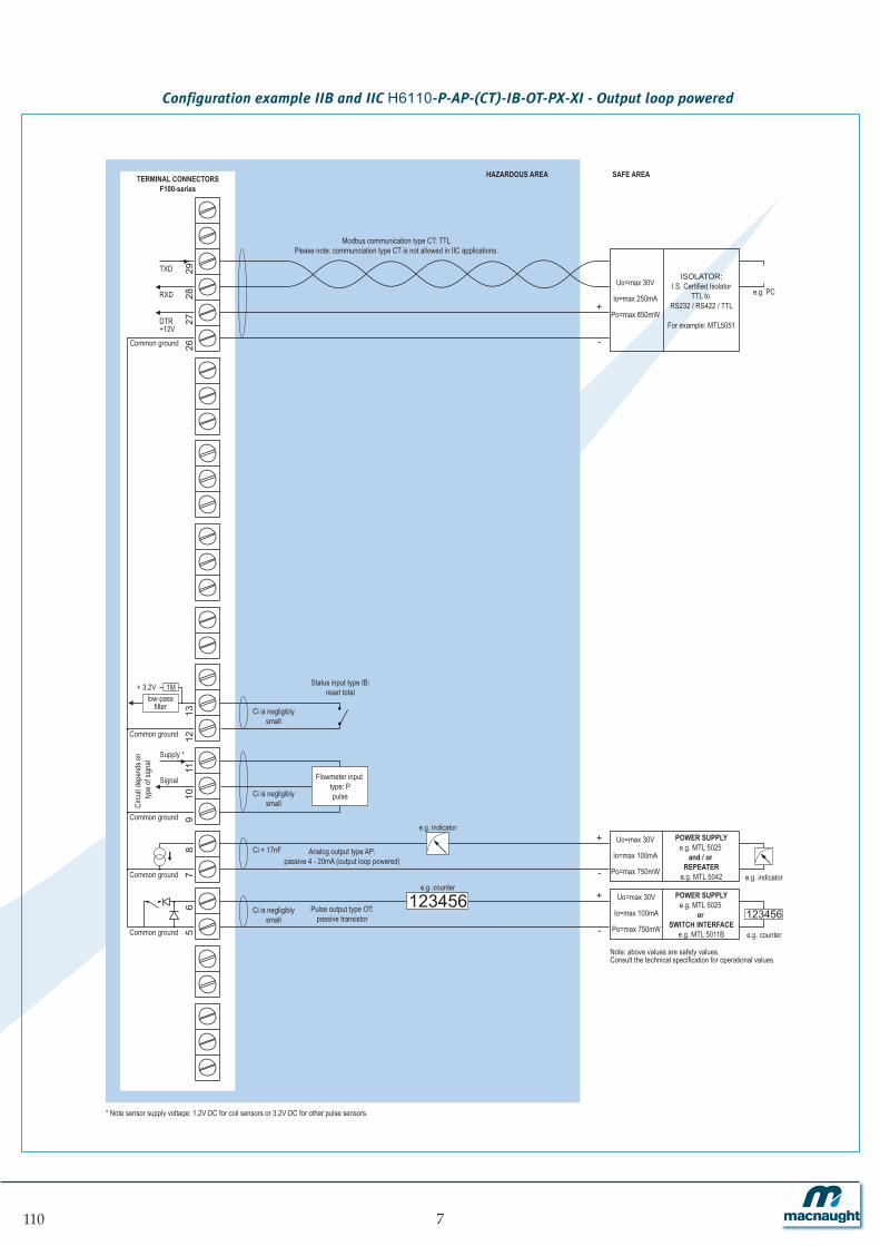
Configuration example IIB and IIC H6110-P-AP-(CT)-IB-OT-PX-XI - Output loop powered
910
11
Common ground
Signal
Supply *
Circu
it dep
ends
on
type o
f sign
al
Analog output type AP:passive 4 - 20mA (output loop powered)
56
Common ground
123456
Ci = 17nF
78
Flowmeter input type: Ppulse
Common grounde.g. counter
+
-
POWER SUPPLYe.g. MTL 5025
and / or REPEATER
e.g. MTL 5042
Uo=max 30V
Io=max 100mA
Po=max 750mW
+
-
POWER SUPPLYe.g. MTL 5025
or SWITCH INTERFACE
e.g. MTL 5011B
Uo=max 30V
Io=max 100mA
Po=max 750mWe.g. counter
123456
e.g. indicator
e.g. indicator
TERMINAL CONNECTORSF100-series
HAZARDOUS AREA SAFE AREA
Status input type IB:reset total
Ci is negligiblysmall
12
13
Common ground
RXD
Common ground
TXD
28
26
29
DTR+12V
27
ISOLATOR:
I.S. Certified IsolatorTTL to
RS232 / RS422 / TTL
For example: MTL5051
Uo=max 30V
Io=max 250mA
Po=max 850mW
+
-
e.g. PC
+ 3.2Vlow-pass
filter
1M
Modbus communication type CT: TTLPlease note: communciation type CT is not allowed in IIC applications.
* Note sensor supply voltage: 1.2V DC for coil sensors or 3.2V DC for other pulse sensors.
Pulse output type OT:passive transistor
Ci is negligiblysmall
Ci is negligiblysmall
Note: above values are safety values.Consult the technical specification for operational values.
7110

Configuration example IIB and IIC - H6110A-AF-(CT)-IB-OT-PD-XI - Power supply 16 - 30V DC
Common ground
TOTAL Co OF ALL CONNECTEDANALOG APPARATUS IN IICAPPLICATIONS MAY NOT EXCEED 66nF MINUS 17nF
(17nF IS USED BY THE ANALOG OUTPUT SIGNAL TERMINAL 7 + 8).
Main supply Power supply type PD: 16 - 30V DC (please note: PD and battery supply (type PC) is NOT allowed in IIC applications).
56
Common ground
01
2
123456
Ci = 17nF Analog output type AF:passive floating 4 - 20mA
78
910
11
Common ground
Signal
Supply *
Circu
it dep
ends
on
type o
f sign
al
Ci is negligiblysmall
Flowmeter input type: A(0)4 - 20mA
e.g. counter
+
-
POWER SUPPLY
For example MTL5025
Uo=max 30V
Io=max 100mA
Po=max 750mW
+
-
POWER SUPPLYe.g. MTL 5025
or SWITCH INTERFACE
e.g. MTL 5011B
Uo=max 30V
Io=max 100mA
Po=max 750mW e.g. counter
123456
e.g. indicator
* Note power supply type PD: the supply voltage to pulse sensors is maximum 8.7V (Uo=max 8.7V Io=max 25mA Po=max 150mW) and to analog sensors as connected to terminal 1 (internally linked).
TERMINAL CONNECTORSF100-series
HAZARDOUS AREA SAFE AREA
Status input type IB:reset total
Ci is negligiblysmall
12
13
Common ground
RXD
Common ground
TXD
28
26
29
DTR+12V
27
ISOLATOR:
I.S. Certified IsolatorTTL to
RS232 / RS422 / TTL
For example: MTL5051
Uo=max 30V
Io=max 250mA
Po=max 850mW
+
-
e.g. PC
+ 3.2Vlow-pass
filter
1M
Modbus communication type CT: TTLPlease note: communciation type CT is not allowed in IIC applications.
Pulse output type OT:passive transistor
Ci is negligiblysmall
Note: above values are safety values.Consult the technical specification for operational values.
8 110

Configuration example IIB - H6110-A-AF-CT-IB-OT-(PC)-(PD)-(PL)-XI - Power supply 16 - 30V DC, battery or loop powered
Ci = 17nF
910
11
Common ground
Common ground
Signal
Supply *
Main supply
Circ
uit de
pend
s on
type o
f sign
al
* Note power supply type PD: the supply voltage to pulse sensors is maximum 8.7V (Uo=max 8.7V Io=max 25mA Po=max 150mW) and to analog sensors as connected to terminal 1 (internally linked).
Power supply type PD: 16 - 30V DC
Analog output type AF:passive floating 4 - 20mA
56
Common ground
01
27
8
123456
Flowmeter input type: A(0)4 - 20mA
e.g. counter
+
-
+
-
POWER SUPPLYe.g. MTL 5025
and / orREPEATER
e.g. MTL 5042
Uo=max 30V
Io=max 100mA
Po=max 750mW
POWER SUPPLY
For example MTL5025
Uo=max 30V
Io=max 100mA
Po=max 750mW
+
-
POWER SUPPLY
For example MTL5025
Uo=max 30V
Io=max 100mA
Po=max 750mW
+
-
POWER SUPPLYe.g. MTL 5025
or SWITCH INTERFACE
e.g. MTL 5011B
Uo=max 30V
Io=max 100mA
Po=max 750mWe.g. counter
123456
e.g. indicator
e.g. indicator
TERMINAL CONNECTORSF100-series
HAZARDOUS AREA SAFE AREA
Status input type IB:reset total
Ci is negligiblysmall
12
13
Common ground
RXD
Common ground
TXD
28
26
29
DTR+12V
27
ISOLATOR:
I.S. Certified IsolatorTTL to
RS232 / RS422 / TTL
For example: MTL5051
Uo=max 30V
Io=max 250mA
Po=max 850mW
+
-
e.g. PC
+ 3.2Vlow-pass
filter
1M
Modbus communication type CT: TTL
Due to analog output type AF, the unit has to be powered with battery type PC, input loop powered type PL or with external power supply type PD.
Pulse output type OT:passive transistor
Ci is negligiblysmall
Ci is negligiblysmall
Note: above values are safety values.Consult the technical specification for operational values.
9110

Technical specificationGeneral
DisplayType High intensity reflective numeric and
alphanumeric LCD, UV-resistant.Dimensions 90 x 40mm (3.5” x 1.6”).Digits Seven 17mm (0.67") and eleven 8mm (0.31") digits.
Various symbols and measuring units.Refresh rate User definable: 8 times/sec. - 30 secs.Option ZB Transflective LCD with green LED backlight.
Good readings in full sunlight and darkness. Note ZB Only available for safe area applications.
Operating temperatureOperational -30°C to +80°C (-22°F to +178°F).Intrinsically Safe -30°C to +70°C (-22°F to +158°F).
Power requirementsType PB Long life Lithium battery - life-time depends upon
settings and configuration - up to 5 years.Type PC Intrinsically Safe long life lithium battery - life-time
depends upon settings and configuration - up to 5 years.
Type PD 8 - 24V AC / DC ± 10%. Power consumption max. 10 Watt. Intrinsically Safe: 16 - 30V DC; power consumption max. 0.75 Watt.
Type PF 24V AC / DC ± 10%. Power consumption max. 15 Watt.Type PL Input loop powered from sensor signal 4 - 20mA
(type “A”) - requires types AI or AF and OT.Type PM 115 - 230V AC ± 10%. Power consumption max. 15 Watt.Type PX 8 - 30V DC. Power consumption max. 0.5 Watt. Type ZB 12 - 24V DC ± 10% or type PD / PF / PM.
Power consumption max. 1 Watt.Note PB/PF/PM Not availble Intrinsically Safe.Note PF/PM The total consumption of the sensors and outputs
may not exceed 400mA @ 24V.Note For Intrinsically Safe applications, consult the safety
values in the certificate.
Sensor excitationType PB/PC/PX 3.2V DC for pulse signals and 1.2V DC for coil pick-up.
Note This is not a real sensor supply. Only suitable for sensors with a very low power consumption like coils(sine wave) and reed-switches.
Type PD 1.2 / 3.2 / 8.2 / 12 / 24V DC - max. 50mA @ 24V DC.Type PD-XI 1.2 / 3.2 / 8.2V DC - max. 7mA @ 8.2V DC and mains
power supply voltage (as connected to terminal 1).Note In case PD-XI and signal A or U: the sensor supply
voltage is according to the power supply voltage connected to terminal 1. Also terminal 2 offers the same voltage.
Type PF / PM 1.2 / 3.2 / 8.2 / 12 / 24V DC - max. 400mA @ 24V DC.
Terminal connectionsType Removable plug-in terminal strip.
Wire max. 1.5mm2 and 2.5mm2.
Data protectionType EEPROM backup of all settings. Backup of running
totals every minute. Data retention at least 10 years.Pass-code Configuration settings can be pass-code protected.
Hazardous areaIntrinsically ATEX certification:Safe Type XI II 1 GD EEx ia IIB/IIC T4 T100°C.
Ambient Ta -30°C to +70°C (-22°F to +158°F).
EnvironmentElectromagnetic Compliant ref: EN 61326 (1997), EN 61010-1 (1993).compatibility
Casing & cable gland entryGeneralWindow Polycarbonate window.Sealing Silicone.Control keys Three industrial micro-switch keys. UV-resistant
silicone keypad.
RA - Aluminum wall / field mount enclosuresGeneral Die-cast aluminum wall/field mount enclosure IP67 /
NEMA 4X with 2-component UV-resistant coating.Dimensions 130 x 120 x 75mm (5.12" x 4.72" x 2.95") - W x H x D.Weight 1100 gr.
Type HA Cable entry: 2 x PG9 and 1 x M20. Type HM Cable entry: 2 x M16 and 1 x M20. Type HU Cable entry: 3 x 1/2" NPT.
RG - GRP wall / field mount enclosuresGeneral GRP wall/field mount enclosure IP67 / NEMA 4X,
UV-resistant and flame retardant. Dimensions 130 x 120 x 75mm (5.12" x 4.72" x 2.95") - W x H x D.Weight 600 gr.
Type HE Cable entry: 2 x Ø 16mm and 1 x Ø 20mm.
ER1- Aluminum round wall / field mount enclosuresGeneral Die-cast aluminum wall/field mount enclosure IP67 /
NEMA 4X with 2-component UV-resistant coating.Dimensions Ø 161 x 85mm (6.34" x 3.35") - Diam. x Depth.Weight 1200 gr.Colors GA: Charcoal or GC: Red.
Type HM Cable entry: 2 x M16 and 1 x M20. Type HU Cable entry: 3 x 1/2" NPT.
1106
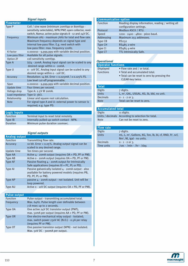
Signal inputsFlowmeterType P Coil / sine wave (minimum 20mVpp or 80mVpp -
sensitivity selectable), NPN/PNP, open collector, reed-switch, Namur, active pulse signals 8 - 12 and 24V DC.
Frequency Minimum 0Hz - maximum 7kHz for total and flow rate. Maximum frequency depends on signal type and internal low-pass filter. E.g. reed switch with low-pass filter: max. frequency 120Hz.
K-Factor 0.000010 - 9,999,999 with variable decimal position.Low-pass filter Available for all pulse signals.Option ZF coil sensitivity 10mVpp.
Type A (0)4 - 20mA. Analog input signal can be scaled to anydesired range within 0 - 20mA.
Type U 0 - 10V DC. Analog input signal can be scaled to any desired range within 0 - 10V DC.
Accuracy Resolution: 14 bit. Error < 0.025mA / ± 0.125% FS. Low level cut-off programmable.
Span 0.000010 - 9,999,999 with variable decimal position.Update time Four times per second.Voltage drop Type A: 2.5V @ 2omA.Load impedance Type U: 3kΩ.Relationship Linear and square root calculation.Note For signal type A and U: external power to sensor is
required; e.g. type PD.
Logic inputsFunction Terminal input to reset total remotely.Type IB Internally pulled-up switch contact - NPN.Duration Minimum pulse duration 100msec.
Signal outputsAnalog outputFunction Transmitting flow rate.Accuracy 10 bit. Error < 0.05%. Analog output signal can be
scaled to any desired range.Update time Ten times per second.Type AA Active 4 - 20mA output (requires OA + PD, PF or PM).Type AB Active 0 - 20mA output (requires OA + PD, PF or PM).Type AF Passive floating 4 - 20mA output for Intrinsically
Safe applications (requires XI + PC, PL or PD).Type AI Passive galvanically isolated 4 - 20mA output - also
available for battery powered models (requires PB, PD, PF, PL or PM).
Type AP passive 4 - 20mA output - not isolated. Unit will beloop powered.
Type AU Active 0 - 10V DC output (requires OA + PD, PF or PM).
Pulse outputFunction Pulse output - transmitting accumulated total.Frequency Max. 64Hz. Pulse length user definable between
7.8 msec up to 2 seconds.Type OA One active 24V DC transistor output (PNP);
max. 50mA per output (requires AA + PD, PF or PM).Type OR One electro-mechanical relay output - isolated;
max. switch power 230V AC (N.O.) - 0.5A per relay (requires PF or PM).
Type OT One passive transistor output (NPN) - not isolated. Max. 50V DC - 300mA per output.
Communication optionFunction Reading display information, reading / writing all
configuration settings.Protocol Modbus ASCII / RTU.Speed 1200 - 2400 - 4800 - 9600 baud.Addressing Maximum 255 addresses.Type CB RS232Type CH RS485 2-wire Type CI RS485 4-wireType CT TTL Intrinsically Safe.
OperationalOperator functionsDisplayed • Flow rate and / or total.Functions • Total and accumulated total.
• Total can be reset to zero by pressing the CLEAR-key twice.
TotalDigits 7 digits.Units L, m3, GAL, USGAL, KG, lb, bbl, no unit.Decimals 0 - 1 - 2 or 3. Note Total can be reset to zero.
Accumulated totalDigits 11 digits.Units / decimals According to selection for total.Note Can not be reset to zero.
Flow rateDigits 7 digits.Units mL, L, m3, Gallons, KG, Ton, lb, bl, cf, RND, ft3, scf,
Nm3, Nl, igal - no units.Decimals 0 - 1 - 2 or 3.Time units /sec - /min - /hr - /day.
Cable gland accessories
110 7
Specifications are subject to change without notice.
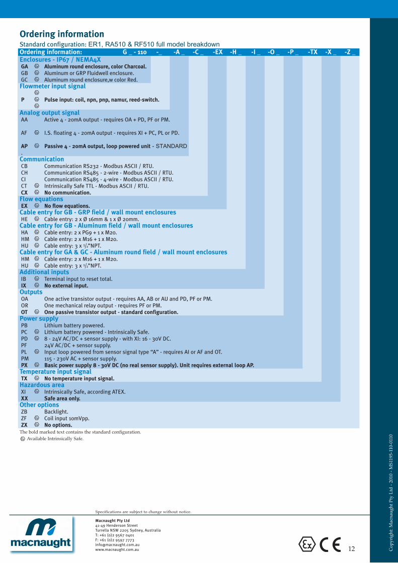
Ordering information Standard configuration: ER1, RA510 & RF510 full model breakdownOrdering information: G _ - 110 -_ -A _ -C _ -EX -H _ -I _ -O _ -P _ -TX -X _ -Z _Enclosures - IP67 / NEMA4XGA Aluminum round enclosure, color Charcoal.GB Aluminum or GRP Fluidwell enclosure.GC Aluminum round enclosure,w color Red.Flowmeter input signal
P Pulse input: coil, npn, pnp, namur, reed-switch.
Analog output signalAA Active 4 - 20mA output - requires OA + PD, PF or PM.
AF I.S. floating 4 - 20mA output - requires XI + PC, PL or PD.
AP Passive 4 - 20mA output, loop powered unit - STANDARD.CommunicationCB Communication RS232 - Modbus ASCII / RTU.CH Communication RS485 - 2-wire - Modbus ASCII / RTU.CI Communication RS485 - 4-wire - Modbus ASCII / RTU.CT Intrinsically Safe TTL - Modbus ASCII / RTU.CX No communication.Flow equationsEX No flow equations.Cable entry for GB - GRP field / wall mount enclosuresHE Cable entry: 2 x Ø 16mm & 1 x Ø 20mm.Cable entry for GB - Aluminum field / wall mount enclosuresHA Cable entry: 2 x PG9 + 1 x M20.HM Cable entry: 2 x M16 + 1 x M20.HU Cable entry: 3 x 1/2”NPT.Cable entry for GA & GC - Aluminum round field / wall mount enclosuresHM Cable entry: 2 x M16 + 1 x M20.HU Cable entry: 3 x 1/2”NPT.Additional inputsIB Terminal input to reset total.IX No external input.OutputsOA One active transistor output - requires AA, AB or AU and PD, PF or PM.OR One mechanical relay output - requires PF or PM.OT One passive transistor output - standard configuration.Power supplyPB Lithium battery powered.PC Lithium battery powered - Intrinsically Safe.PD 8 - 24V AC/DC + sensor supply - with XI: 16 - 30V DC.PF 24V AC/DC + sensor supply.PL Input loop powered from sensor signal type “A” - requires AI or AF and OT.PM 115 - 230V AC + sensor supply.PX Basic power supply 8 - 30V DC (no real sensor supply). Unit requires external loop AP.Temperature input signalTX No temperature input signal.Hazardous areaXI Intrinsically Safe, according ATEX.XX Safe area only.Other optionsZB Backlight. ZF Coil input 10mVpp.ZX No options.
The bold marked text contains the standard configuration.Available Intrinsically Safe.
Macnaught Pty Ltd
41-49 Henderson Street Turrella NSW 2205 Sydney, Australia T: +61 (0)2 9567 0401 F: +61 (0)2 9597 7773 [email protected] C
opyr
ight
: Mac
naug
ht P
ty L
td -
201
0 -
MS1
195-
110-
0110
12