flow meter fmo page 23 - 42 compteur volumétri- …€¦ · flow meter fmo page 23 - 42 compteur...
TRANSCRIPT

Originalbetriebsanleitung
Original main operating instructions
Notice d’instructions générale originale
DEUTSCH
Flüssigkeits-Mengenmesser FMO Seite 2 - 22 Flow Meter FMO Page 23 - 42 Compteur volumétri-que FMO Page 43 - 63

Operating instructions FMO 23 / 64
ENGLISH
Content
1 General Information ......................................................................................... 24
1.1 Scope of delivery ................................................................................................ 24
1.2 Liability, warranty and guarantee ........................................................................ 24
1.3 Further applicable documents ............................................................................ 24
1.4 Storing operating instructions ............................................................................. 24
1.5 Markers .............................................................................................................. 25
1.6 Symbols and signs ............................................................................................. 25
1.7 Safety instructions .............................................................................................. 26
1.8 Safety information for areas at risk from explosion ............................................. 27
2 General information on the device .................................................................. 29
3 Description of Device ....................................................................................... 30
3.1 FMO flow meter (oval rotor design) .................................................................... 30
3.2 Filling Accuracy with the FMO (oval rotor design) ............................................... 31
4 Before starting operation ................................................................................ 32
5 Mounting Instructions ...................................................................................... 33
6 Commissioning ................................................................................................ 33
7 In operation ...................................................................................................... 33
8 Repair ................................................................................................................ 34
8.1 Change of FLUXTRONIC, panel or seal ............................................................. 34
9 Technical data .................................................................................................. 36
9.1 Pressure loss ..................................................................................................... 36
9.2 Technical data .................................................................................................... 36
9.3 Plug connection with FMO 1 and FMO 2 in hall/reed version ............................. 37
10 EC Declaration of Conformity ......................................................................... 38
11 EC-Type-Examination Certificate .................................................................... 39

___
24/64 Operating instructions FMO
ENGLISH
1 General Information
1.1 Scope of delivery
Please check the delivery according to the delivery note.
Also check the delivery for completeness and integrity.
Do not operate damaged devices.
These operating instructions and corresponding attachments with additional information on the supplied components are part of the delivery scope.
1.2 Liability, warranty and guarantee
Upon acceptance of the product, the operating company accepts operation responsibility.
The warranty period is 12 months from the date of delivery.
According to our general terms and conditions of sale, this warranty shall only apply
provided that:
� the product has been used for its intended use and in accordance with the present operating instructions.
� assembly, commissioning and operation have been carried out in a professional and appropriate manner.
� repair has only been performed by authorised and qualified persons.
� only genuine spare parts have been used.
The safety instructions highlighted in these operating instructions and in the corre-sponding attachments must always be observed. We will not accept liability for any damages or failures due to non-compliance with these operating instructions.
This manufacturer warranty is void for any damages and failures resulting from unauthorised alterations or modifications of the product.
1.3 Further applicable documents
In addition to these operating instructions, you are provided with the following docu-ments: � Attachments with additional information in accordance with the components
supplied. The documents are contained in the product-specific attachments.
� Resistance chart (on request).
1.4 Storing operating instructions
These operating instructions with the related attachments must be available to the operator at all times.
Operating instructions FMO 25 / 64
ENGLISH
1.5 Markers
These markers will help you to understand the operating instructions. For your orientation, the following formatting is used:
� Listings of a descriptive nature are marked with the symbol "•" at the beginning of the line.
� Instructions are marked with the symbol ">" at the beginning of the line.
1.6 Symbols and signs
Safety instructions are marked by � a safety sign and � a danger warning
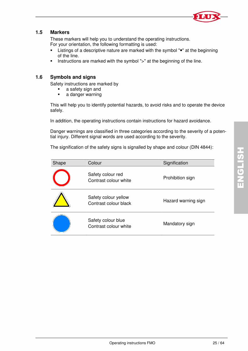
This will help you to identify potential hazards, to avoid risks and to operate the device safely. In addition, the operating instructions contain instructions for hazard avoidance. Danger warnings are classified in three categories according to the severity of a poten-tial injury. Different signal words are used according to the severity. The signification of the safety signs is signalled by shape and colour (DIN 4844):
Shape Colour Signification
Safety colour red
Contrast colour white Prohibition sign
Safety colour yellow
Contrast colour black Hazard warning sign
Safety colour blue
Contrast colour white Mandatory sign

26 / 64 Operating instructions FMO
ENGLISH
1.7 Safety instructions
All safety instructions must be observed and followed.
Failure to follow the safety instructions may lead to serious injury or death or cause environmental and/or property damage. Adherence to the safety instructions contained in these operating instructions will help you to avoid risks, to operate the hand nozzle efficiently and to ensure that the product is used to its full potential.
Safety instructions on the activities are listed at the start of the respective chapter. Special safety instructions on individual action steps are given under the respective action step.
Attention!
• Make sure that the operator has read and understood the operating instructions.
Danger!
Danger of poisoning from harmful substances / vapours
- Take off spilled harmful substances.
- Never eat or drink when filling harmful liquids.
Attention!
Danger from splashing liquids!
• The maximum operating pressure and operating temperature must not be exceeded.
• High operating pressure may result in the containers or the hoses bursting or becoming loose. Make sure that excessive pressure does not result when filling a container.
• Fill carefully and at an appropriate speed to avoid leakage of the liquid.
Caution!
Immediately inform the responsible supervisor about defects on the device.
Operating instructions FMO 27 / 64
ENGLISH
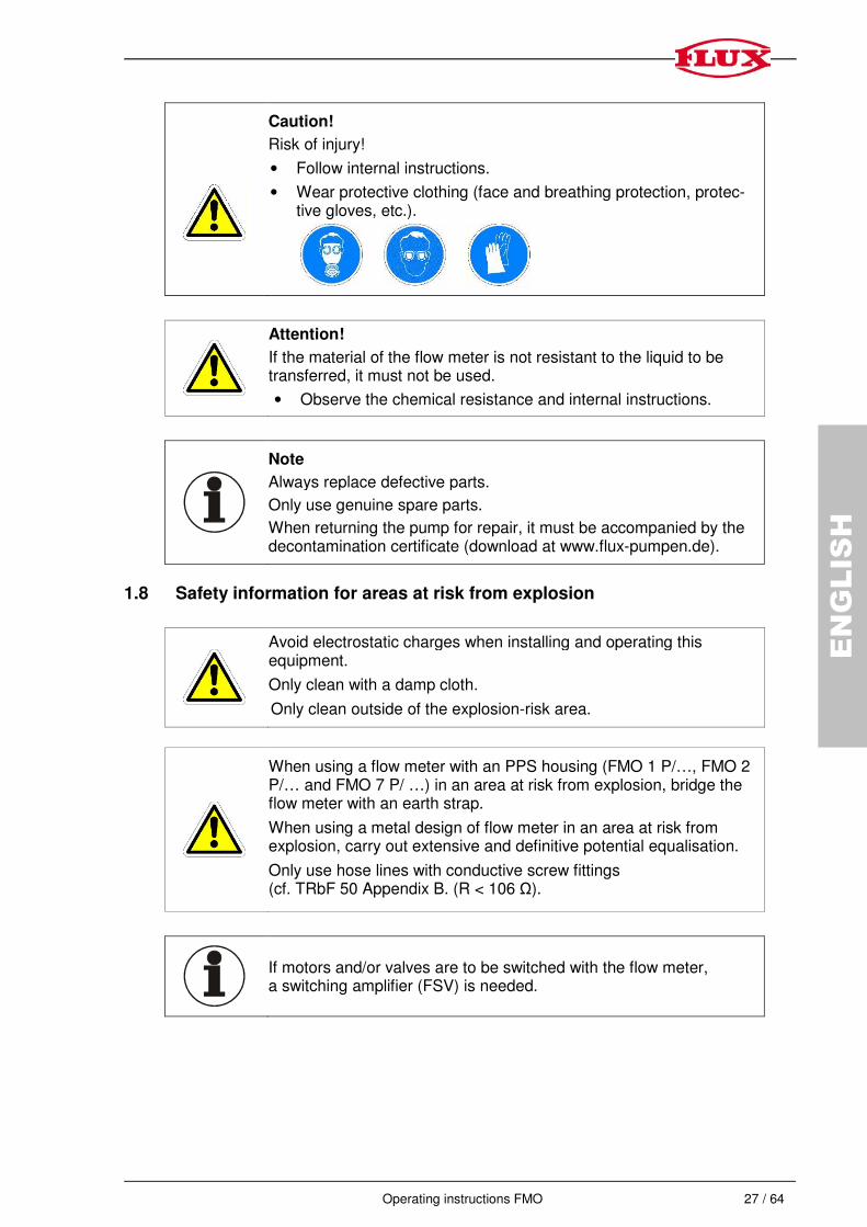
Caution!
Risk of injury!
• Follow internal instructions.
• Wear protective clothing (face and breathing protection, protec-tive gloves, etc.).
Attention!
If the material of the flow meter is not resistant to the liquid to be transferred, it must not be used.
• Observe the chemical resistance and internal instructions.
Note
Always replace defective parts.
Only use genuine spare parts.
When returning the pump for repair, it must be accompanied by the decontamination certificate (download at www.flux-pumpen.de).
1.8 Safety information for areas at risk from explosion
Avoid electrostatic charges when installing and operating this equipment.
Only clean with a damp cloth.
Only clean outside of the explosion-risk area.
When using a flow meter with an PPS housing (FMO 1 P/…, FMO 2 P/… and FMO 7 P/ …) in an area at risk from explosion, bridge the flow meter with an earth strap.
When using a metal design of flow meter in an area at risk from explosion, carry out extensive and definitive potential equalisation.
Only use hose lines with conductive screw fittings (cf. TRbF 50 Appendix B. (R < 106 Ω).
If motors and/or valves are to be switched with the flow meter, a switching amplifier (FSV) is needed.
28 / 64 Operating instructions FMO
ENGLISH
The use of the electronic analysis unit FLUXTRONIC in areas at risk of explosion means that it is necessary to select a signal interface permitted in areas at risk from explosion. This is not the case with all available switching amplifiers. The NAMUR* interface is a proven one and meets all of the above requirements.
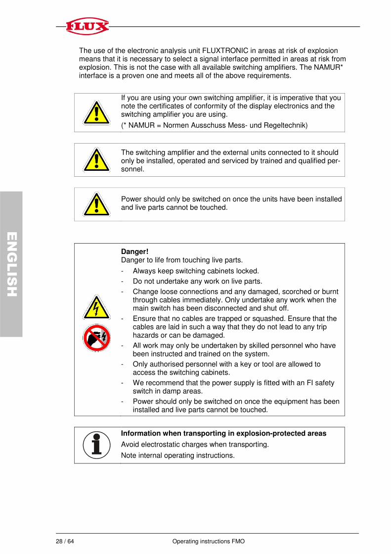
If you are using your own switching amplifier, it is imperative that you note the certificates of conformity of the display electronics and the switching amplifier you are using.
(* NAMUR = Normen Ausschuss Mess- und Regeltechnik)
The switching amplifier and the external units connected to it should only be installed, operated and serviced by trained and qualified per-sonnel.
Power should only be switched on once the units have been installed and live parts cannot be touched.
Danger! Danger to life from touching live parts.
- Always keep switching cabinets locked.
- Do not undertake any work on live parts.
- Change loose connections and any damaged, scorched or burnt through cables immediately. Only undertake any work when the main switch has been disconnected and shut off.
- Ensure that no cables are trapped or squashed. Ensure that the cables are laid in such a way that they do not lead to any trip hazards or can be damaged.
- All work may only be undertaken by skilled personnel who have been instructed and trained on the system.
- Only authorised personnel with a key or tool are allowed to access the switching cabinets.
- We recommend that the power supply is fitted with an FI safety switch in damp areas.
- Power should only be switched on once the equipment has been installed and live parts cannot be touched.
Information when transporting in explosion-protected areas
Avoid electrostatic charges when transporting.
Note internal operating instructions.
Operating instructions FMO 29 / 64
ENGLISH
2 General information on the device
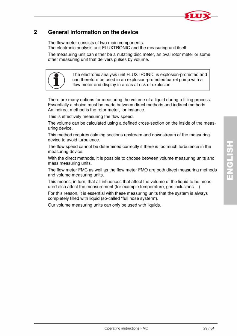
The flow meter consists of two main components: The electronic analysis unit FLUXTRONIC and the measuring unit itself.
The measuring unit can either be a nutating disc meter, an oval rotor meter or some other measuring unit that delivers pulses by volume.
The electronic analysis unit FLUXTRONIC is explosion-protected and can therefore be used in an explosion-protected barrel pump with a flow meter and display in areas at risk of explosion.
There are many options for measuring the volume of a liquid during a filling process. Essentially a choice must be made between direct methods and indirect methods. An indirect method is the rotor meter, for instance.
This is effectively measuring the flow speed.
The volume can be calculated using a defined cross-section on the inside of the meas-uring device.
This method requires calming sections upstream and downstream of the measuring device to avoid turbulence.
The flow speed cannot be determined correctly if there is too much turbulence in the measuring device.
With the direct methods, it is possible to choose between volume measuring units and mass measuring units.
The flow meter FMC as well as the flow meter FMO are both direct measuring methods and volume measuring units.
This means, in turn, that all influences that affect the volume of the liquid to be meas-ured also affect the measurement (for example temperature, gas inclusions ...).
For this reason, it is essential with these measuring units that the system is always completely filled with liquid (so-called "full hose system").
Our volume measuring units can only be used with liquids.

30 / 64 Operating instructions FMO
ENGLISH
3 Description of Device
3.1 FMO flow meter (oval rotor design)
Oval rotor meters are volume measuring units. Two oval shaped gearwheels interlock.
The mesh point of the gears is always outside the middle of the two axles. The gear-
wheels are moved by the liquid. The rotating movement of the gearwheels is transferred
outwards by permanent magnets and is recorded there by a sensor. This is displayed
with an electronic evaluation. The volume of the measuring chamber is split differently
depending on the size of the gearwheels, the toothing, the number of magnets and the
number of reed sensors (cf. Technical Data table).
1 Electronic analysis unit
2 Plate with reed-sensor
3 Magnet
4 Oval rotor
5 Housing
3
5
4
2
1

Operating instructions FMO 31 / 64
ENGLISH
3.2 Filling Accuracy with the FMO (oval rotor design)
The FLUXTRONIC can convert the switching processes of the sensor into the volume and display this.
A pre-requisite for as precise a filling process as possible is that the entire system is always completely filled with liquid ("full hose system"). The following points must be taken into consideration to ensure that the above accuracy is achieved:
- Fill without interruption.
- The flow speed must be constant.
- The flow volume should not exceed or fall below the flow volume for which the unit
is designed.
In automatic mode:
- The opening and closing times of the valves used must always be the same.
- The temperature must be constant.
- The viscosity must be constant.
- There should be no air bubbles in the liquid.

32 / 64 Operating instructions FMO
ENGLISH
4 Before starting operation
Check the chemical resistance to the liquid and to any possible cleaning agents. The flow meter must be installed without any mechanical tension. When installed stationary within a plant, fit the flow meter into the pipework with pipe connections on both sides. In the event of a defect, the flow meter can be simply and quickly removed and re-fitted. A T-section should also be used downstream of the second pipe fitting on the liquid meter to 1. Allow for calibration without having to dismantle it. 2. Shut off the pipe work so that the unit can be removed with ease.
Pressure surges that are greater than the nominal pressure stated on the type plate (see technical data) can damage the flow meter.
Important: Pressure surges are produced by mass forces (content of long pipes) that are caused by quick-closing fittings!
Keep organic solvents away from the keyboard and LCD display.

Operating instructions FMO 33 / 64
ENGLISH
5 Mounting Instructions
In mounting the flow meter type FMO make sure that neither the bottom nor the cover of the meter housing will be ground off by the weight of the oval rotors.
It is important that after initial installation you fill the line slowly, high speed air purge could cause damage to the oval rotors.
6 Commissioning
Attention!
If the material of the flow meter is not resistant to the liquid to be transferred, it must not be used.
• Observe the chemical resistance and internal operating instructions.
Note!
Check if the materials of the flow meter are appropriate for the applications.
Note!
Generally replace a defect signalling cable.
7 In operation
Regularly check the flow meter for function.
34 / 64 Operating instructions FMO
ENGLISH
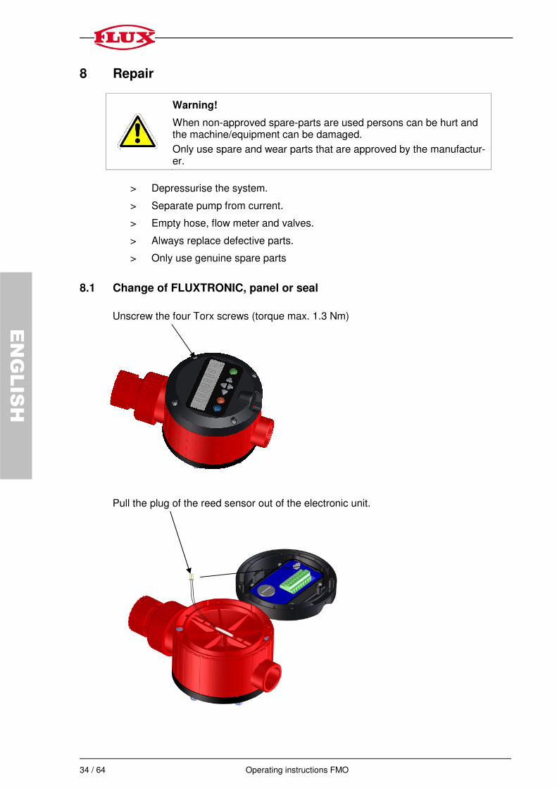
8 Repair
Warning!
When non-approved spare-parts are used persons can be hurt and the machine/equipment can be damaged.
Only use spare and wear parts that are approved by the manufactur-er.
> Depressurise the system.
> Separate pump from current.
> Empty hose, flow meter and valves.
> Always replace defective parts.
> Only use genuine spare parts
8.1 Change of FLUXTRONIC, panel or seal
Unscrew the four Torx screws (torque max. 1.3 Nm)
Pull the plug of the reed sensor out of the electronic unit.

Operating instructions FMO 35 / 64
ENGLISH
Remove the 4 Torx screws (torque max. 0.5 Nm)
Electronic
Silicone foam insulation
Panel
36 / 64 Operating instructions FMO
ENGLISH
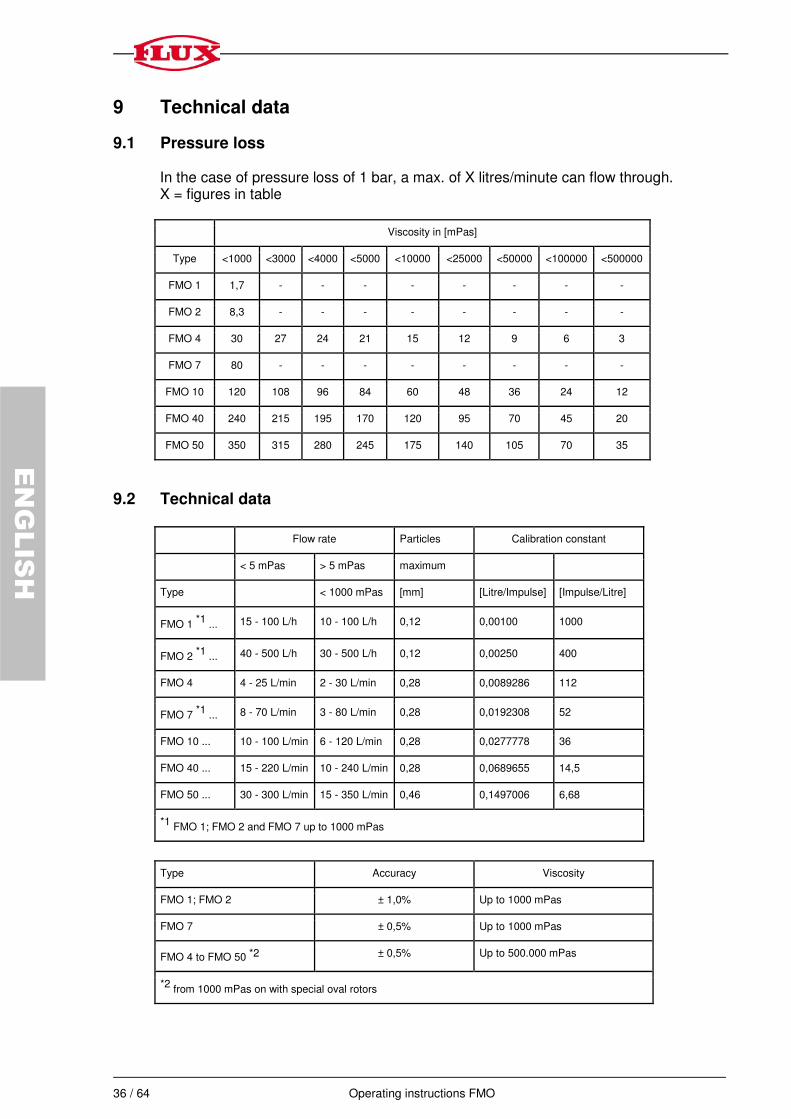
9 Technical data
9.1 Pressure loss In the case of pressure loss of 1 bar, a max. of X litres/minute can flow through. X = figures in table
Viscosity in [mPas]
Type <1000 <3000 <4000 <5000 <10000 <25000 <50000 <100000 <500000
FMO 1 1,7 - - - - - - - -
FMO 2 8,3 - - - - - - - -
FMO 4 30 27 24 21 15 12 9 6 3
FMO 7 80 - - - - - - - -
FMO 10 120 108 96 84 60 48 36 24 12
FMO 40 240 215 195 170 120 95 70 45 20
FMO 50 350 315 280 245 175 140 105 70 35
9.2 Technical data
Flow rate Particles Calibration constant
< 5 mPas > 5 mPas maximum
Type < 1000 mPas [mm] [Litre/Impulse] [Impulse/Litre]
FMO 1 *1
... 15 - 100 L/h 10 - 100 L/h 0,12 0,00100 1000
FMO 2 *1
... 40 - 500 L/h 30 - 500 L/h 0,12 0,00250 400
FMO 4 4 - 25 L/min 2 - 30 L/min 0,28 0,0089286 112
FMO 7 *1
... 8 - 70 L/min 3 - 80 L/min 0,28 0,0192308 52
FMO 10 ... 10 - 100 L/min 6 - 120 L/min 0,28 0,0277778 36
FMO 40 ... 15 - 220 L/min 10 - 240 L/min 0,28 0,0689655 14,5
FMO 50 ... 30 - 300 L/min 15 - 350 L/min 0,46 0,1497006 6,68
*1 FMO 1; FMO 2 and FMO 7 up to 1000 mPas
Type Accuracy Viscosity
FMO 1; FMO 2 ± 1,0% Up to 1000 mPas
FMO 7 ± 0,5% Up to 1000 mPas
FMO 4 to FMO 50 *2 ± 0,5% Up to 500.000 mPas
*2 from 1000 mPas on with special oval rotors

Operating instructions FMO 37 / 64
ENGLISH
Operating pressure
Type
Material
Meter
body
Material
Oval rotors
Temperature
of liquid
FM
O1; F
MO
2
FM
O 7
FM
O 4
to F
MO
50
FM
O 4
0 .../F
L
FM
O 5
0 .../F
L
FMO .../P/P PPS PPS Up to 80°C 5 bar 10 bar - - -
FMO .../S/P Stainless
steel 316L PPS Up to 80°C 10 bar - 55 bar 16 bar 16 bar
FMO .../S/S Stainless
steel 316L
Stainless
steel 316L Up to 120°C 10 bar - 55 bar 16 bar -
FMO .../AL/P Aluminium PPS Up to 80°c - - 55 bar 16 bar 16 bar
9.3 Plug connection with FMO 1 and FMO 2 in hall/reed version
The shielding of the cable is “black”.
When the FLUXTRONIC is connected with the FMO 1 or 2 the Reed switch is connect-ed as pulse generator. At the plug connector ST2 the brown line must only be connect-ed with PIN 9 and the grey line only with PIN 6. The connection lines of the hall sensor cannot be used and must not be connected with ST 2. The lines that are not used (green, yellow and white) can be isolated with a shrinkable tube so that no incidental contact occurs.
Attention!
The hall sensor must not be used in explosion risk areas.
For security reasons only the cables that are used should be connected.
If, for example, only signal S1 is used, only the green line PIN 4 (+ NAMUR) and the white line PIN 8 (- NAMUR) should be connected.
Hall: green (gn) 0V DC
Hall: yellow (ge) 4,5 V – 24 V DC 4,6 mA min.
Reed: grey (gr) GND (-) ST 2 PIN 8
Reed: brown (br) +3 V DC ST 2 Pin 9
Hall: white (ws) Signal max. 25 mA
38 / 64 Operating instructions FMO
ENGLISH
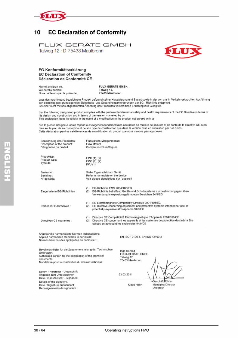
10 EC Declaration of Conformity
Operating instructions FMO 39 / 64
ENGLISH
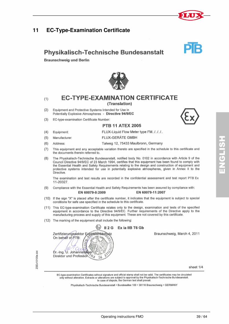
11 EC-Type-Examination Certificate

40 / 64 Operating instructions FMO
ENGLISH

Operating instructions FMO 41 / 64
ENGLISH
42 / 64 Operating instructions FMO
ENGLISH

FB
00
186
193
_0
2 0
312
/0,5
_D
EF