flow assurance work processocw.snu.ac.kr/sites/default/files/note/3.1 production...gas processing -...
TRANSCRIPT

Offshore Equipment
Yutaek Seo
Components for offshore process
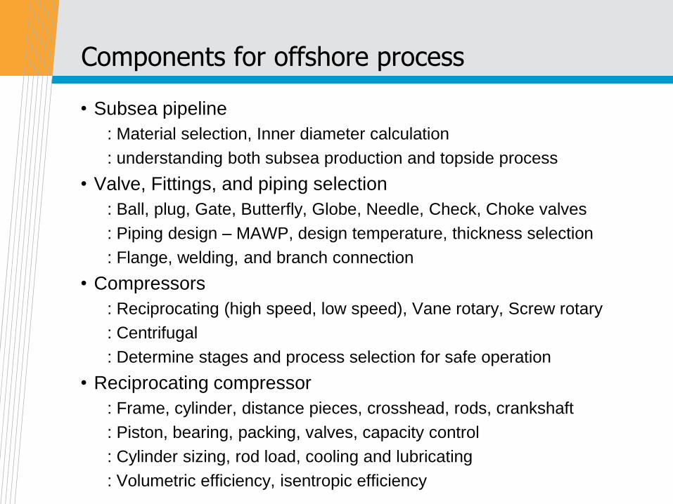
• Subsea pipeline
: Material selection, Inner diameter calculation
: understanding both subsea production and topside process
• Valve, Fittings, and piping selection
: Ball, plug, Gate, Butterfly, Globe, Needle, Check, Choke valves
: Piping design – MAWP, design temperature, thickness selection
: Flange, welding, and branch connection
• Compressors
: Reciprocating (high speed, low speed), Vane rotary, Screw rotary
: Centrifugal
: Determine stages and process selection for safe operation
• Reciprocating compressor
: Frame, cylinder, distance pieces, crosshead, rods, crankshaft
: Piston, bearing, packing, valves, capacity control
: Cylinder sizing, rod load, cooling and lubricating
: Volumetric efficiency, isentropic efficiency
Introduction
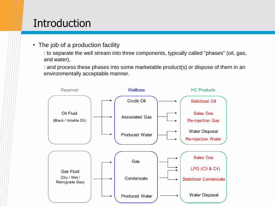
• The job of a production facility
: to separate the well stream into three components, typically called "phases" (oil, gas,
and water),
: and process these phases into some marketable product(s) or dispose of them in an
environmentally acceptable manner.

• Specification for pipeline quality gas
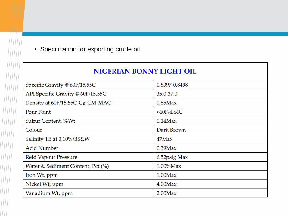
• Specification for exporting crude oil
Primary separation
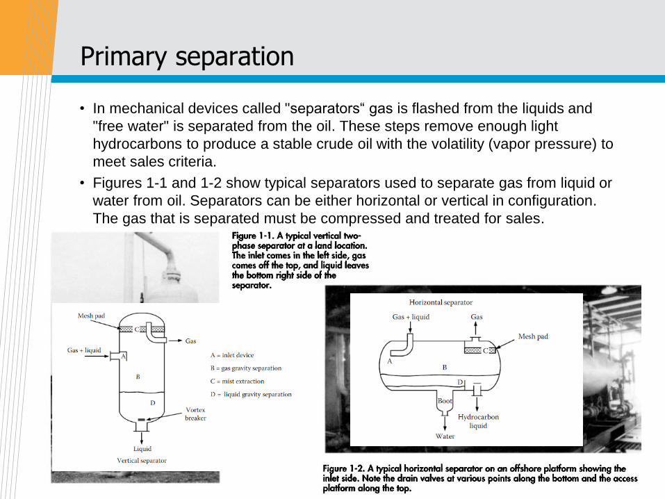
• In mechanical devices called "separators“ gas is flashed from the liquids and
"free water" is separated from the oil. These steps remove enough light
hydrocarbons to produce a stable crude oil with the volatility (vapor pressure) to
meet sales criteria.
• Figures 1-1 and 1-2 show typical separators used to separate gas from liquid or
water from oil. Separators can be either horizontal or vertical in configuration.
The gas that is separated must be compressed and treated for sales.
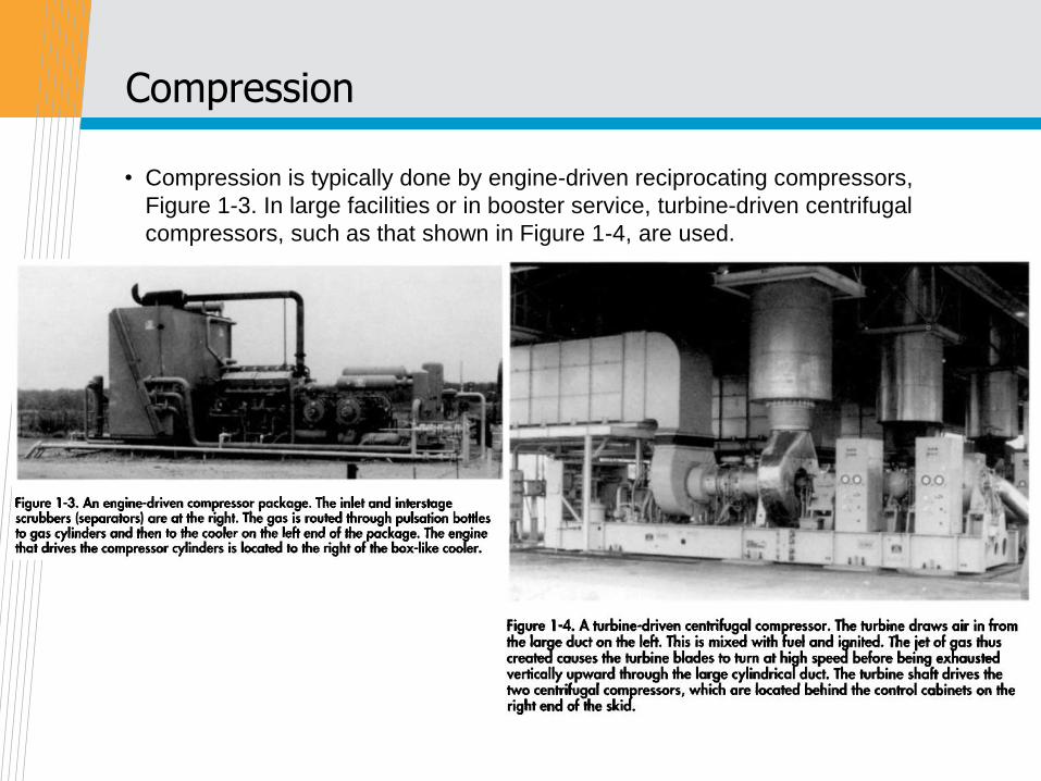
Compression
• Compression is typically done by engine-driven reciprocating compressors,
Figure 1-3. In large facilities or in booster service, turbine-driven centrifugal
compressors, such as that shown in Figure 1-4, are used.
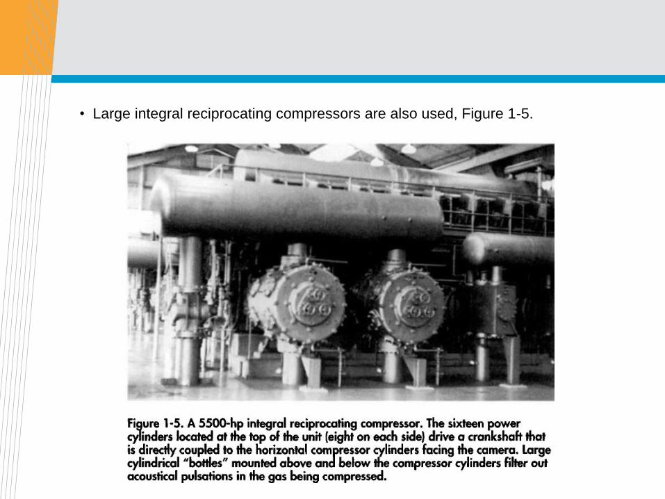
• Large integral reciprocating compressors are also used, Figure 1-5.
Gas processing - dehydration
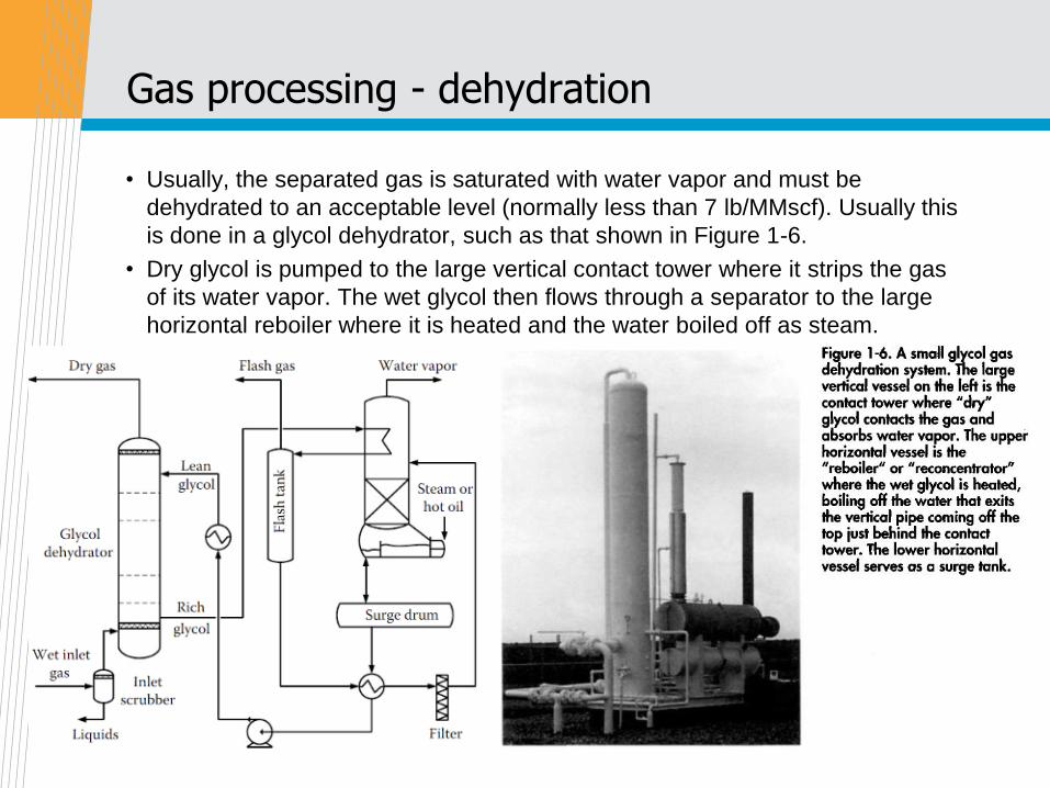
• Usually, the separated gas is saturated with water vapor and must be
dehydrated to an acceptable level (normally less than 7 lb/MMscf). Usually this
is done in a glycol dehydrator, such as that shown in Figure 1-6.
• Dry glycol is pumped to the large vertical contact tower where it strips the gas
of its water vapor. The wet glycol then flows through a separator to the large
horizontal reboiler where it is heated and the water boiled off as steam.

Gas processing – NGL recovery
• In some locations it may be necessary to remove the heavier hydrocarbons to
lower the hydrocarbon dew point.

Gas processing – Acid gas removal
• Contaminants such as H2S and CO2 may be present at levels higher than those
acceptable to the gas purchaser. If this is the case, then additional equipment
will be necessary to "sweeten" the gas.

Oil processing
• The oil and emulsion from the separators must be treated to remove water.
Most oil contracts specify a maximum percent of basic sediment and water (BS
and W) that can be in the crude. This will typically vary from 0.5% to 3%
depending on location.
• Some refineries have a limit on salt content in the crude, which may require
several stages of dilution with fresh water and subsequent treating to remove
the water. Typical salt limits are 10 to 25 pounds of salt per thousand barrels.

Oil processing – direct fired heater treater
• Figures 1-7 and 1-8 are typical direct-fired heater-treaters that are used for
removing water from the oil and emulsion being treated.
• These can be either horizontal or vertical in configuration and are distinguished
by the fire tube, air intakes, and exhausts that are clearly visible. Treaters can
be built without fire tubes, which makes them look very much like separators.
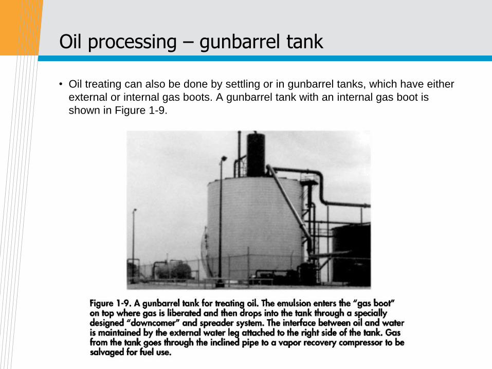
Oil processing – gunbarrel tank
• Oil treating can also be done by settling or in gunbarrel tanks, which have either
external or internal gas boots. A gunbarrel tank with an internal gas boot is
shown in Figure 1-9.
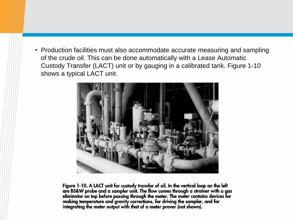
• Production facilities must also accommodate accurate measuring and sampling
of the crude oil. This can be done automatically with a Lease Automatic
Custody Transfer (LACT) unit or by gauging in a calibrated tank. Figure 1-10
shows a typical LACT unit.
Water treating
• The water that is produced with crude oil can be disposed of overboard in most
offshore areas, or evaporated from pits in some locations onshore. Usually, it is
injected into disposal wells or used for water flooding.
• In any case, water from the separators must be treated to remove small
quantities of produced oil. If the water is to be injected into a disposal well,
facilities may be required to filter solid particles from it.
Water treating – oil removing
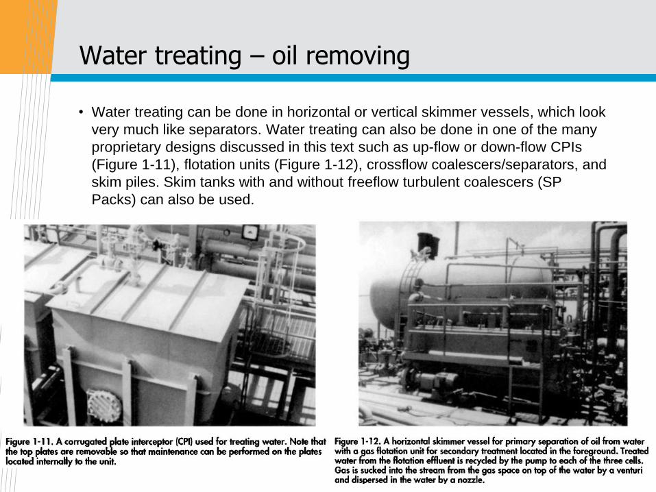
• Water treating can be done in horizontal or vertical skimmer vessels, which look
very much like separators. Water treating can also be done in one of the many
proprietary designs discussed in this text such as up-flow or down-flow CPIs
(Figure 1-11), flotation units (Figure 1-12), crossflow coalescers/separators, and
skim piles. Skim tanks with and without freeflow turbulent coalescers (SP
Packs) can also be used.
Water processing - desander
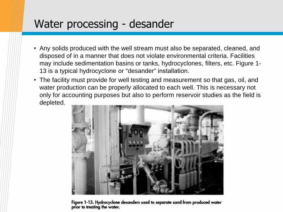
• Any solids produced with the well stream must also be separated, cleaned, and
disposed of in a manner that does not violate environmental criteria. Facilities
may include sedimentation basins or tanks, hydrocyclones, filters, etc. Figure 1-
13 is a typical hydrocyclone or "desander“ installation.
• The facility must provide for well testing and measurement so that gas, oil, and
water production can be properly allocated to each well. This is necessary not
only for accounting purposes but also to perform reservoir studies as the field is
depleted.
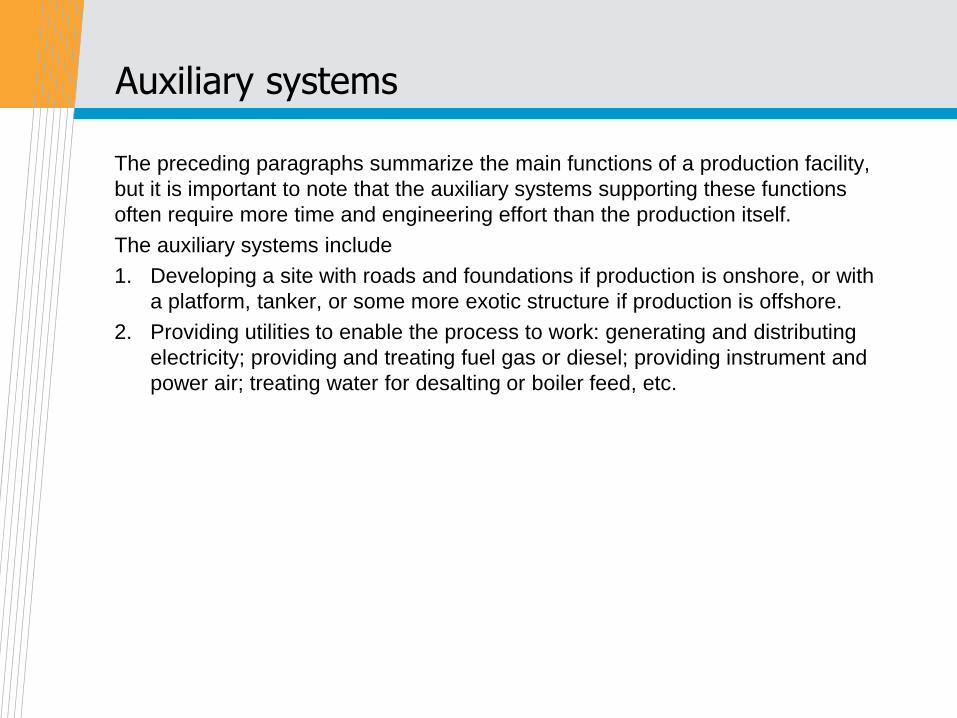
Auxiliary systems
The preceding paragraphs summarize the main functions of a production facility,
but it is important to note that the auxiliary systems supporting these functions
often require more time and engineering effort than the production itself.
The auxiliary systems include
1. Developing a site with roads and foundations if production is onshore, or with
a platform, tanker, or some more exotic structure if production is offshore.
2. Providing utilities to enable the process to work: generating and distributing
electricity; providing and treating fuel gas or diesel; providing instrument and
power air; treating water for desalting or boiler feed, etc.
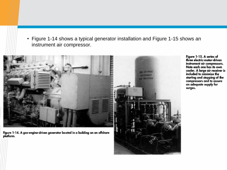
• Figure 1-14 shows a typical generator installation and Figure 1-15 shows an
instrument air compressor.
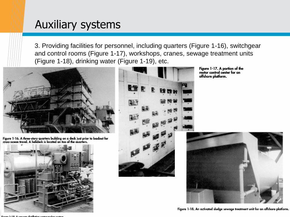
Auxiliary systems
3. Providing facilities for personnel, including quarters (Figure 1-16), switchgear
and control rooms (Figure 1-17), workshops, cranes, sewage treatment units
(Figure 1-18), drinking water (Figure 1-19), etc.
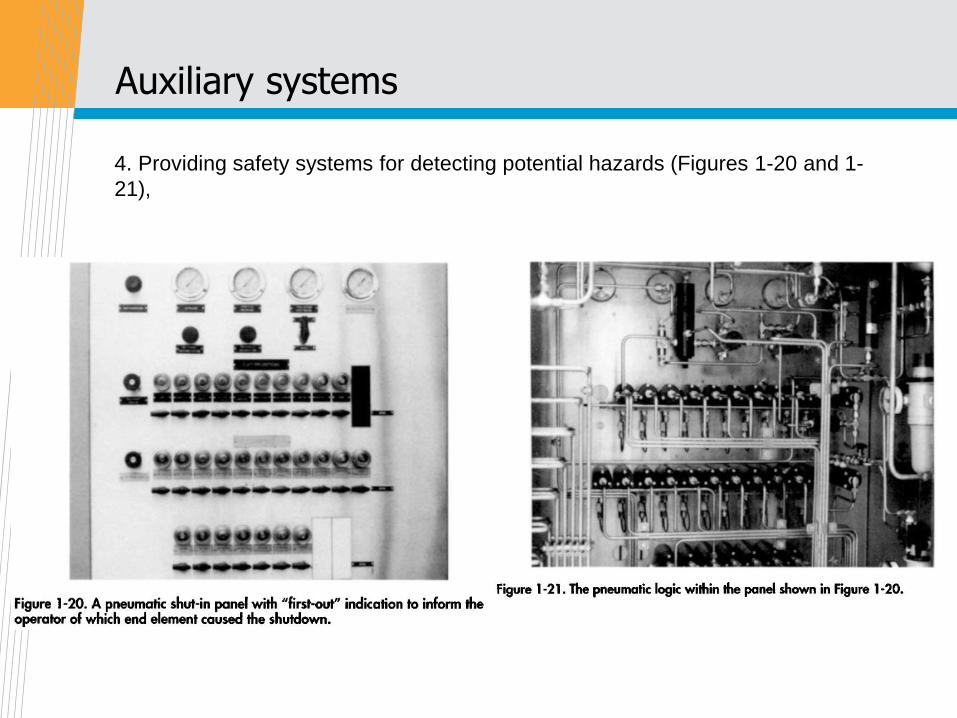
Auxiliary systems
4. Providing safety systems for detecting potential hazards (Figures 1-20 and 1-
21),
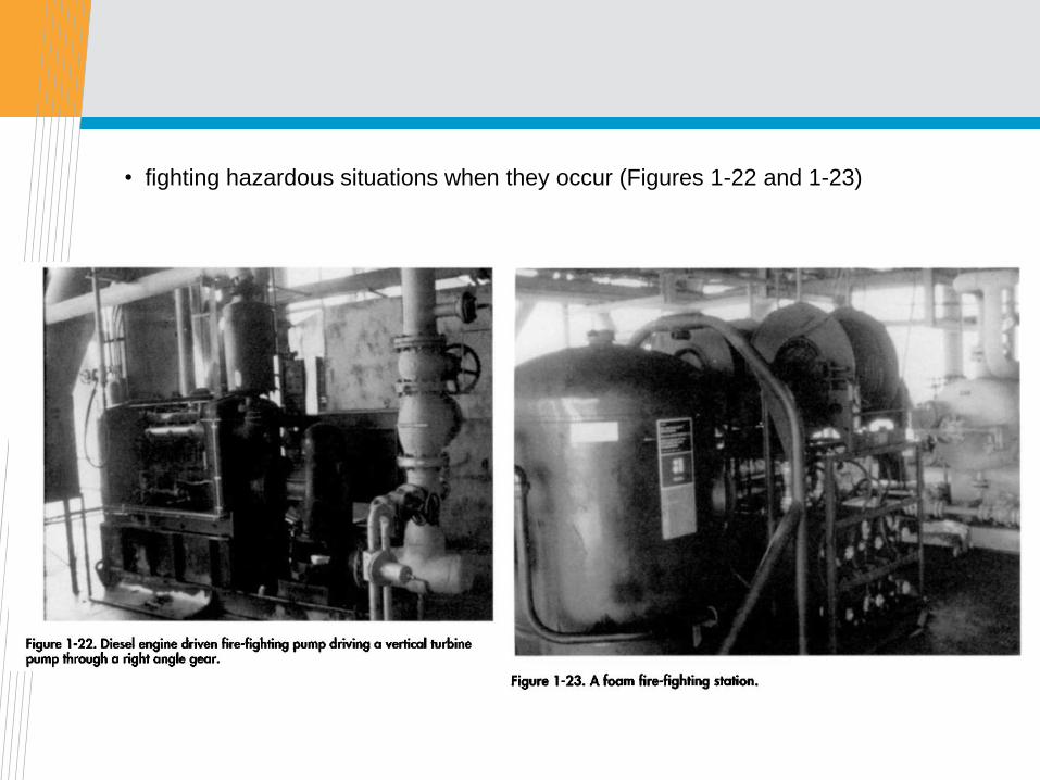
• fighting hazardous situations when they occur (Figures 1-22 and 1-23)

• and for personnel protection and escape (Figure 1-24).

Making the equipment work
• The main items of process equipment have automatic instrumentation that
controls the pressure and/or liquid level and sometimes temperature within the
equipment. Figure 1-25 shows a typical pressure controller and control valve.
• In the black box (the controller) is a device that sends a signal to the actuator,
which opens/closes the control valve to control pressure.
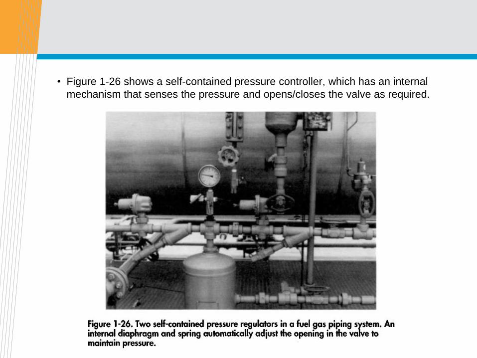
• Figure 1-26 shows a self-contained pressure controller, which has an internal
mechanism that senses the pressure and opens/closes the valve as required.
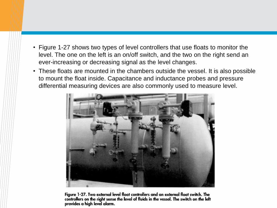
• Figure 1-27 shows two types of level controllers that use floats to monitor the
level. The one on the left is an on/off switch, and the two on the right send an
ever-increasing or decreasing signal as the level changes.
• These floats are mounted in the chambers outside the vessel. It is also possible
to mount the float inside. Capacitance and inductance probes and pressure
differential measuring devices are also commonly used to measure level.
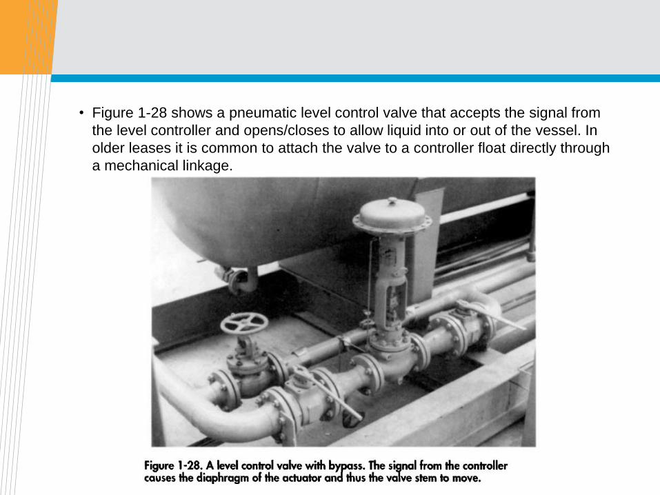
• Figure 1-28 shows a pneumatic level control valve that accepts the signal from
the level controller and opens/closes to allow liquid into or out of the vessel. In
older leases it is common to attach the valve to a controller float directly through
a mechanical linkage.
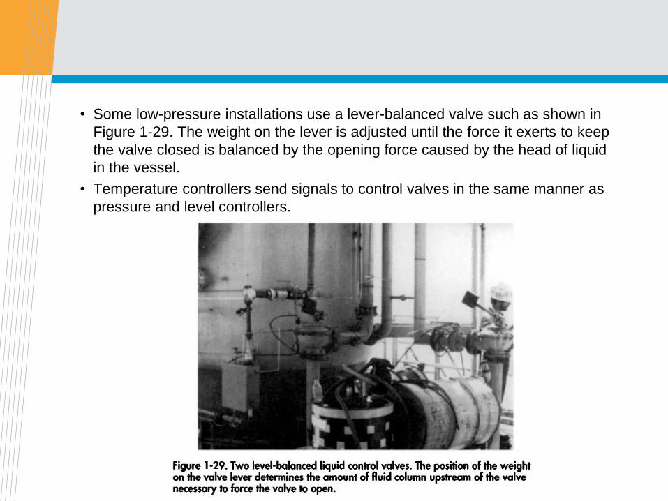
• Some low-pressure installations use a lever-balanced valve such as shown in
Figure 1-29. The weight on the lever is adjusted until the force it exerts to keep
the valve closed is balanced by the opening force caused by the head of liquid
in the vessel.
• Temperature controllers send signals to control valves in the same manner as
pressure and level controllers.
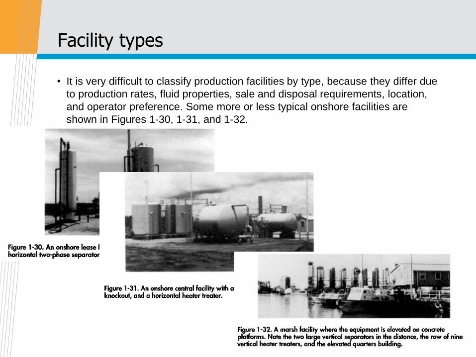
Facility types
• It is very difficult to classify production facilities by type, because they differ due
to production rates, fluid properties, sale and disposal requirements, location,
and operator preference. Some more or less typical onshore facilities are
shown in Figures 1-30, 1-31, and 1-32.
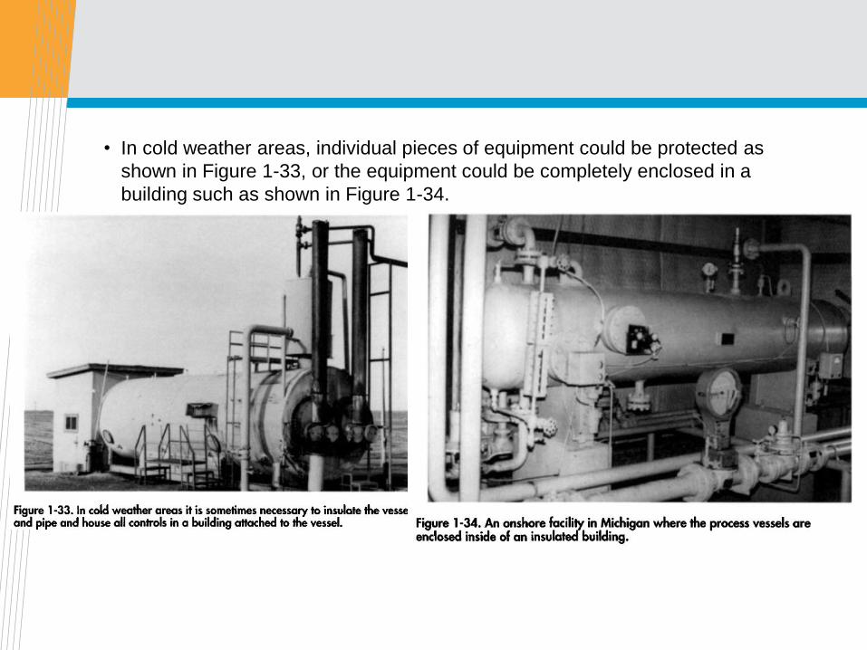
• In cold weather areas, individual pieces of equipment could be protected as
shown in Figure 1-33, or the equipment could be completely enclosed in a
building such as shown in Figure 1-34.
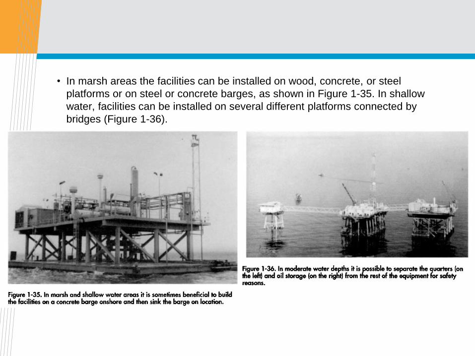
• In marsh areas the facilities can be installed on wood, concrete, or steel
platforms or on steel or concrete barges, as shown in Figure 1-35. In shallow
water, facilities can be installed on several different platforms connected by
bridges (Figure 1-36).
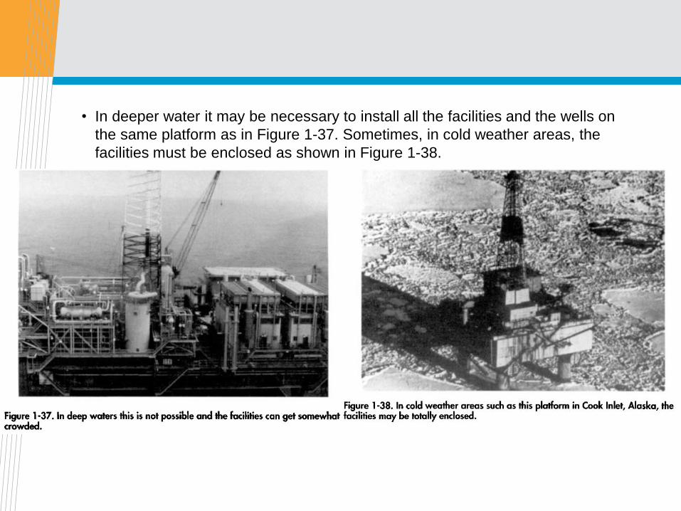
• In deeper water it may be necessary to install all the facilities and the wells on
the same platform as in Figure 1-37. Sometimes, in cold weather areas, the
facilities must be enclosed as shown in Figure 1-38.
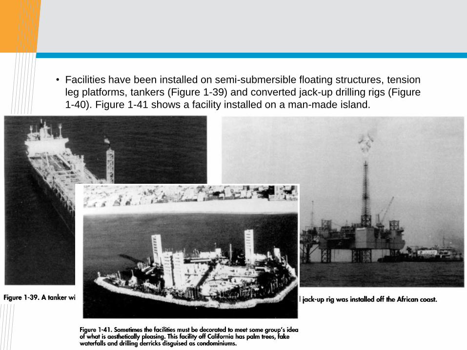
• Facilities have been installed on semi-submersible floating structures, tension
leg platforms, tankers (Figure 1-39) and converted jack-up drilling rigs (Figure
1-40). Figure 1-41 shows a facility installed on a man-made island.

Thank you, Question?
?