flow and congestion controls for datacenter …hpsr2014.ieee-hpsr.org/docs/fcc t4 fc v1.3.pdfflow...
TRANSCRIPT

Flow and Congestion Controls for
Datacenter Networks - 1
L2 Flow Control
A Converged Enhanced Ethernet-centric View of Physical
and Virtual DCNs
Presented by Mitch Gusat
IBM Research, Zurich Lab
FCC Tutorial @ HSPR’14 Vancouver

2
Outline #1: Link Level Flow Control for DCN / SDN
1. Why lossless?
2. Flow control 101: FC schemes
1. On/Off Grants (PAUSE); Credits, abs. & incremental;Rate
3. Practical LL-FC, i.e., standard
1. Ethernet: from .3x PAUSE to .1Qbb PFC
* PFC Benefits and Drawbacks (extras, refs)
1. PFC in CEE: App. and TCP impact (Short&Fat, TCP Incast)
2. PFC in Virtual DCNs: zOVN as fix to SDN losses
3. All things considered: The good; Bad/HOL/sat-tree; Ugly/DLK... (transition to CC?)

3
Why lossless?
� Qual. : Must-have, or,
� When Comp & Comm meet (2 views of the e2e argument)
• “Wire-once” convergence: ICTN->HPC...->SAN...-> LAN
� Quant.: The Terra-gap from BER to pkt loss rate

4
Computer Interconnects vs. Communication Networks
Communication switches(Prizma generation 1 + 2)
HPC (PERCS, Mare Nostrum/Incognito)
Optical SwitchingOsmosis 0
1
N-1
input ports
output ports
0 1 2 3 N-1
PRIZMA- CI (opto electronic - gen. 3)
NxN NxN
NxN
NxN NxN NxN NxN
NxN NxN
NxN NxN NxN NxN NxN NxN
NxN NxN NxN NxN NxN NxN
BNT Datacenters, SDN, Storage

IBM Zurich Research Lab 5
Comp: From Interconnect to HPC Datacenters
• MareNostrum: IBM BladeCenter computing nodes + SAN/Myrinet + LAN/GigEthernet
MareNostrum
4 switch racks
� Nice on the surface
� Lots of cables, $ and Wattbeneath
�Primary needsHigh performance
Non-standard network is acceptablePower and coolingLeading edge technologyLow capital cost

IBM Zurich Research Lab 6
Fabric Convergence
Servers Multiple Fabrics Converged Fabric
Datacenter Fabric Convergence � Value Proposition
Improved RASReduced failure points, time, misconnections, bumping.
Lower CostLess adapters, cables & switches
Lower power/thermals.
Simpler ManagementSingle physical fabric to manage.Simpler to deploy, upgrade and
maintain.

7
Requirements of the “DCN”
� Native support for
� Blades
• L: ~1us for short messages (IPC, MPI, cache blocks)
• Bw: min. 10, roadmap to 400+ Gbps; low half-power point (ideal < 100B)
• 0 loss = core idea of DC-ICTNs (mission-critical)
� Storage
• SCSI ( if frame loss => 2-3 minutes timeout)
• RDMA (TOE, iWARP) @ L2: light and reliable LL transport
� LAN-like mgnt.
• Virtualization
• QoS: VL separation per traffic type (IPC, IO, storage, IP) and class (high / low prio)
=> support for both lossless and lossy traffic
� TCP-friendly flows => fairness, RTT-dependency
� Cost ~ (10s-100s) $/port @ 10/40/100/... Gbps
� Power
� Open: Standard (L0-L2) & Source (L3-7)

IBM Zurich Research Lab 8
Red Shift in the Datacenter: Migration to Layer 2
1. Aggregated � Converged Enhanced Ethernet (IEEE 802 DCB)
• FCoE: FC over CEE +
• ROCE: RDMA over CEE +
• HPC, IB, Myrinet, SCSI... etc. “over E”
-------------------------------------------------------
UNIFIED WIRE = CEE L2 “wire once”
2. Virtualized: Multi-tenants share the $ DCN
• Overlaid: Maintain IP connectivity + VM mobility
• SDN-ed : Flexibility and freedom ☺
• OF-ed: Centralized, distributed? Pendulum swings...
3. Reliable, aka “Lossless”
• via L2 Priority Flow Control (PFC, 802.1Qbb )
4. Work conserving (ETS)
5. Multipath load-balanced (ECMP/LAG+), congestion managed (QCN)

IBM Research GmbH, Zurich Research Laboratory 9
Quantitative Reasons for Lossless Links
• Performance
� The Terra-gap from BER to pkt loss rate
• Typical BER: ~ 10-12..-15
� Few errors/min @ 40Gbps
• Pkt (tail) drop ratios: ~ 0.01 – 5% (up to 70% in SDN)
� Many drops/us @ 40Gbps
• While no link is perfect, the distance from BER to the RED pkt loss could be drastically reduced by LL-FC

10
hotspot
Lossless ICTN or Best-Effort Ethernet + TCP/IP?A tale of two collapses: ICTN vs. BE Ethernet (w/ TCP)
� Persistent oversubscription of a resource: τ > 5x RTT0
� Flow interference -> HO-HOL blocking -> saturation tree -> ‘catastrophic’ collapse (Pfister ‘85) => the $ of LL-FC…!
� With uniform traffic� ICTN remains stable (linear in
Tp and L) for λIN > .6� Adaptive routing and FC can
extend stability > . 7 (.9) � CM handles congestion only
0 0
1 1
0 0
1 1
0 0
1 1
0 0
1 1
0 0
1 1
0 0
1 1
0 0
1 1
0 0
1 1
0 0
1 1
0 0
1 1
0 0
1 1
0 0
1 1
000
001
010
011
101
110
110
111
DestinationsSources
s1 s2 s3λIN λ0 λ1
λ0-λ1
λ3λ2
λ0-λ3 λ1-λ3
λ2-λ3λ1-λ2
λ2-λ3
� contention -> pkt drop -> NAK -> RTX -> ... -> collapse
λi+1 = 1 – (1- λi+1 / n)n
� idealized queuing model
� instant retransmissions (RTX)
� up to 40% optimistic Tput ->
� Latency
1st dependency on RTX, not flight + switching + queuing =>
Prob. pkt dropped K-times = F(RTX fraction) = F(λ0-λ3) / λ0)
The above is with uniform traffic. What if a hotspot…?
If bottleneck on S3 egress:
λ3 -> 0 => RTX fraction -> 1.0 => λIN -> 0
.37256
.3832
.418
.522
TputmaxSwitch degree
hotspot

11
Best Effort Ethernet vs. Lossless ICTN?
Best effort Ethernet- high latency, low Tput⇒ Bw and power wasted on
re-re-transmissionsyet POPULAR…
Tput [%]
log L [µs]
5226 38 74 82 93
Tpmax BE Tpmax lossless
Δ Tpavg = .44 (100%)
311
Lossless ICTN / CEE+ solves Ethernet RTX => LL-FC+ separates functions
1. Linear region: (adaptive) routing, FC2. Congestion: use of dedicated CM...

12
L2 Flow Control Foundations
1. The basic concept of TX-RX flow control
2. FC schemes1. On/Off Grants (PAUSE)
2. Credits, abs. & incremental
3. Rate
3. Props and features
4. Grants vs. credits (and rate)

13
The Flow Control Principle: No Buffer Overflow

14
Comparison of Lossless LL-FC Schemes
• Main LL-FC methods: On/Off Grant, Credit, Rate
� ACK/NACK w/ RTX not considered on L2 (as done by TCP)
• Evaluation of the 3 FC candidates
� Practically feasible implementations
� Similar conditions of correctness and memory (M)
� Core schemes only, without optimizations which may boost the performance of
either scheme:
� link RTT = 4 MTUs (normalized to pkt size)
*Note: rate is harder to fairly compare in correctness, performance and complexity.

15
FC-Basics: On/Off Grants (PAUSE)
Xbar
Up-stream Link
Down-stream Links
VOQ Memory
per row OQ
Threshold
Stop
Go
“Over-run”=
Send STOP
Up-stream Link
Down-stream Links
VOQ Memory
per row OQ
PAUSE BP Semantics :STOP / GO / STOP..
Threshold
Stop
Go
“Over-run”=
Send STOP

16
FC-Basics: Credits
Xbar

17
Correctness: Min. Memory for “No Drop” @ BDP=4
� "Minimum“: to operate lossless => O(RTTlink)– Credit : 1 credit = 1 memory location– Grant : 5 (=RTT+1) memory locations
� Credits– Under full load the credit is circulating constantly– RTT=4, therefore the maximum performancedetermined by up- link utilisation = 25%
� Grants– Determined by slow restart (poor up- link utilisation) : GO, if last packet has
left switch needs RTT until next packet arrives at switch

18
PAUSE vs. Credit @ M = RTT+1
�"Equivalent" = ‘fair’ comparison–Credit scheme: 5 credit = 5 memory locations–Grant scheme: 5 (=RTT+1) memory locations
–Performance loss for PAUSE/Grants is due to lack of underflow protection (pipeline bubbles on restart)For equivalent (to credit) performance, M=9 is required for PAUSE

19
• RX queue Qi=1 (full capacity).
• Max. flow (input arrivals) during one timestep (Dt = 1) is
1/8.
• Goal: update the TX probability Ti from any sending node
during the time interval [t, t+1) to obtain the new Ti
applied during the time interval [t+1, t+2).
• Algorithm for obtaining Ti(t+1) from Ti(t) ... =>
• Initially the offered rate from source0 was set = .100 , and from source1 = .025. All other processing rates were .125.
Hence all queues show low occupancy.
• At timestep 20, the flow rate to the sink was reduced to
.050 => causing a congestion level in Queue2 of .125/.050
= 2.5 times processing capacity.
• Results: The average queue occupancies are .23 to .25, except Q3 = .13. The source flows are treated about
equally and their long-term sum is about .050 (optimal).
FC-Basics: Rate

20
Which LL-FC Scheme is “Better”? It depends...
• Grant / PAUSE
+ simple
+ scalable (lower overhead of signalling)
- 2x M=BDP size required
• Credits (absolute or incremental)
+ are always lossless, independent of the RTT and memory size
+ adopted by virtually all modern ICTNs (IBA, PCIe, FC, HT, ...)
- not trivial for buffer-sharing (incr.)
- protocol reliability (incr.) � census of ghosts and zombies
- scalability and overhead (abs.)
• At equal M = RTT, credits show ca. 30% higher Tput vs. PAUSE
• Rate: in-between PAUSE and credits
+ OK for NICs with h/w RLs
+ potential good match for QCN and CCA (e2e CM)
- complexity (cheap fast bridges)
21
Practical LL-FC
1. Ethernet: from .3x PAUSE to .1Qbb PFC

Introductory Overview of DCB Ethernet
Standardization Activities
in IEEE 802
DCB Redshifting: Learning from the higher layer protocols � L2

IBM Research GmbH, Zurich Research Laboratory 23
Ethernet before DCB
• Traditional Ethernet philosophy: good enough� KISS, Plug&Play => low cost, to buy and to use
� 30 yrs. of continous development
� major iteration once every ca. 10-15 yrs
• Good match for TCP/IP stack
• Not optimized for performance, nor for DC / HPC apps
� Frame loss
� Latency
� Throughput
� Jitter, fairness, no VL, no true QoS (besides .1Q/p)

24
…and after CEE / 802 DCB
The promise of DCB: 802-standard Ethernet with
1. Low latency, comparable w/ best HPC ICTNs
2. Quasi-Losslessness (zero drop)
3. Traffic class differentiation (e2e SLA)
4. Congestion (aka delay/Tput) mgnt
5. Bw sharing (ETS, prio grouping)
6. DC capability detection and exchange (DCBX)
� Vendor specific
� Deadlock mgnt
� Load balancing, adaptive routing, intelli-hashing for LAG
� Schedulers
� ….
PFC = Per Priority
Flow Control
8x worse than PAUSE...?!

26
802.3x � .1 Qbb Priority Flow Control
• Conventional Ethernet is PnP, yet it drops pkts (fixed by L4)
• Layer 2 flow control: 802.3x PAUSE � 802.1Qbb PFC
26
Upstream (TX) Downstream (RX)
Low
>1 RTT1 RTT
High EmptyFull
Pause UnPause
Input bufferOutput queue
Low
>1 RTT1 RTT
High EmptyFullInput bufferOutput queue

27
PFC: 802.1Qbb - Priority-based Flow Control
� Target: Create a VL-like lossless Ethernet (also fix the .3x PAUSE…)
� Why fix a .3 problem in .1?
� A) .1 has queues, whereas .3 doesn’t…
� B) tightly coupled w/ the other .1 DCB proposals, especially QCN (802 internal dependency) and ETS
� PFC enables
� flow control per traffic class; TC is identified by the VLAN tag priority values.
� multiple datacenter networks (DCN), including those serving loss- sensitive protocols - - e.g. inter- processor
communication (IPC), storage (FCoE), etc. to be converged onto an IEEE 802 network.
� PFC is intended to eliminate frame loss due to congestion, thru a mechanism similar to the 802.3x PAUSE,
but operating on individual priorities… PFC complements Congestion Notification (aka QCN) in DCB.
PFC basic operation: A vector of max. 8 Prio PAUSEs w/ explicit timer value/Prio
� PFC request_operands = {priority_enable_vector | time_vector}
� priority_enable_vector = { 00000000 | e[7..0] }
� time_vector = 8*2B => 8 * [0..64K] * pause_quanta * 64B (512 bit time)
� Common size of RX_Buffer > 10KB (10Gbps, short link)

28
Link Level PFC
A B
100G/400G/1000GbE BW
VCI (Reserved bandwidth)
‘n’
Priorities
or Flows
11/4/2012IBM Corporation Confidential 28
Priority Flow Contro
lPriority Flow Control

29
PFC Frame Format
Source MAC Address
0x8808 MAC Control Eth type.
MAC Control Opcode (0x0101)
Priority-Enable VectorPriority-Enable Vector
Time Quanta (Class 0)
Time Quanta (Class 1)
Time Quanta (Class 2)
Time Quanta (Class 3)
Time Quanta (Class 4)
Time Quanta (Class 5)
Time Quanta (Class 6)
Time Quanta (Class n)
Remaining Byte PaddingRemaining Byte Padding
Checksum
ReservedReservedE[n]…..E[0]
Class Vector {0,1}
Unicast Dest MAC Address
11/4/2012IBM Corporation Confidential 29

3030
PFC Delay Model
MAC Sec
MAC Control
MAC
Reconciliation
XGXS
XGXS
PCS
PMA
PMD
PHY
Interface Delay
ETS PFC802.1
802.3DATA CONTROL
QUEUES
MAC Sec
MAC Control
MAC
Reconciliation
XGXS
XGXS
PCS
PMA
PMD
ETSPFC
DATACONTROL
QUEUES
HIGHER LAYER DELAY
MEDIUM

3131
PFC Max Total Delay Calculations
Max Total Delay = 2 * (Max Frame Size)
+ PFC Frame
+ 2 * (Cable Delay)
+ 2 * (Interface Delay)
+ (Higher Layer Service Delay)
Max Total Delay = 2 * (Max Frame Size)
+ PFC Frame
+ 2 * (Cable Delay)
+ 2 * (Interface Delay)
+ (Higher Layer Service Delay)
Cable Delay = Medium Length * 1/(BT * v)
Where BT = Bit Time
v = Speed of light in medium.
Considering, refractive index of optics = 1.467; Speed of light in single mode
fiber = 66% of light speed in vacuum (Ether).
Cable Delay = Medium Length * 1/(BT * v)
Where BT = Bit Time
v = Speed of light in medium.
Considering, refractive index of optics = 1.467; Speed of light in single mode
fiber = 66% of light speed in vacuum (Ether).

32
Potential PFC Issues
DLK mgnt: prevention or
recovery
Deadlocks (DLK)Persistent PAUSE or
cycles (loops, RQ/Reply)
Adaptive routing &
Congestion mgnt. (AR+CM)
Saturation tree hotspot
congestion spreading
10s to 100s us
Re-sequencing at
destination (RSQ @ DST)
Out of order (OOO) w/
Link Aggregation (LAG)
Transient PFC activation:
0.1 – 10 us
SolutionProblemPFC Issue
Consequences
1. “One sublink being Paused may have a ripple effect on the entire aggregated link”
2. .3az Energy Efficient Ethernet ?• Link unavailable during speed change: EEE will produce short term (1ms?) link unavailability
• Frames will be delayed (blocked) during link unavailability => hotspot (unless discarded, !PFC)
• Link speed will produce latency variation; speed change affects available bandwidth
• ...

IBA LL Credit Scheme
VL[0..14]

IBM Research GmbH, Zurich Research Laboratory 34
Keshav
• insert 3-5 foils

35
PFC Final ToughtsAdvantages :
•Link level losslessness.
•Priority based buffer management.
•Priority based traffic management.
•Simple.
•Works beautifully well ☺.
Short-comings :
•Head of line blocking within priority groups.
•XON/XOFF like behavior, although delay quanta are programmable.
•Higher Buffer requirements [ Port Speed and Cable length.]
•Lacks flow control at virtual port level. Does not enable flow control at smaller
slices of bandwidth.
•Suffers due to RTT delays.
•Was not built into original Ethernet standard. Thus not backward interoperable.
LL-FC Deadlocks
aka, the Preventable Ugly
VL[0..14]

37
M2M Circular Dependency Deadlocks

38
The Mechanism of LL-FC-induced Deadlocks
• When incorrectly implemented, LL-FC-based flow control can cause hogging and deadlocks
• LL-FC-deadlocking in shared-memory switches:
� Switches A and B are both full (within the granularity of an MTU or Jumbo) => LL-FC thresholds exceeded
� All traffic from A is destined to B and viceversa
� Neither can send, waiting on each other indefinitely: Deadlock.
� Note: Traffic from A never takes the path from B back to A and vice versa
� Due to shortest- path routing
A
B
39
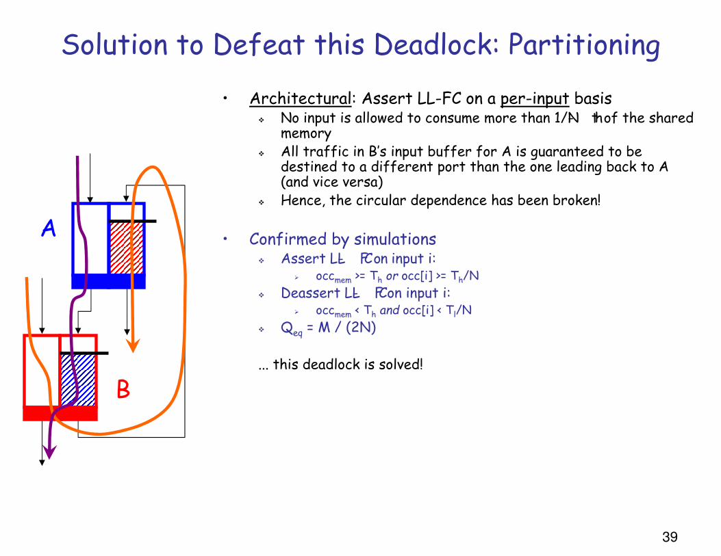
Solution to Defeat this Deadlock: Partitioning
• Architectural: Assert LL-FC on a per-input basis� No input is allowed to consume more than 1/N- th of the shared
memory� All traffic in B’s input buffer for A is guaranteed to be
destined to a different port than the one leading back to A (and vice versa)
� Hence, the circular dependence has been broken!
• Confirmed by simulations� Assert LL- FC on input i:
� occmem >= Th or occ[i] >= Th/N
� Deassert LL- FC on input i:� occmem < Th and occ[i] < Tl/N
� Qeq = M / (2N)
... this deadlock is solved!
A
B

40
LL-FC-caused Deadlocks in BCN Simulations 16-node 5-stage fabric Bernoulli traffic
SM, no BCN
SM, BCN
Partitioned, w/ BCN
Partitioned, no BCN

IBM Research 41
BKUP

42
Routing Deadlocks

43
Routing Deadlock Scenario
VoIP connection
FTP Up load
Video streaming
Def.: Cyclic dependency relationship between two or more resources that are waiting on each other to free resources, but without freeing their own. Resources: physical (hardware) or logical (software)

44
Deadlocked Buffers: Dependency Loop in the Routing Graph
All buffers in this network cycle are full
⇒All the packets are waiting for each other
⇒ Thus, no message can make forward progress.

45
Deadlock Recovery in Lossy Networks
TIMEOUT
Packet Drop
Packet drop=> frees deadlocked resources ⇒ eliminates cycles between their inter-dependencies.⇒ simplest solution, iff voluntary loss is allowed
46
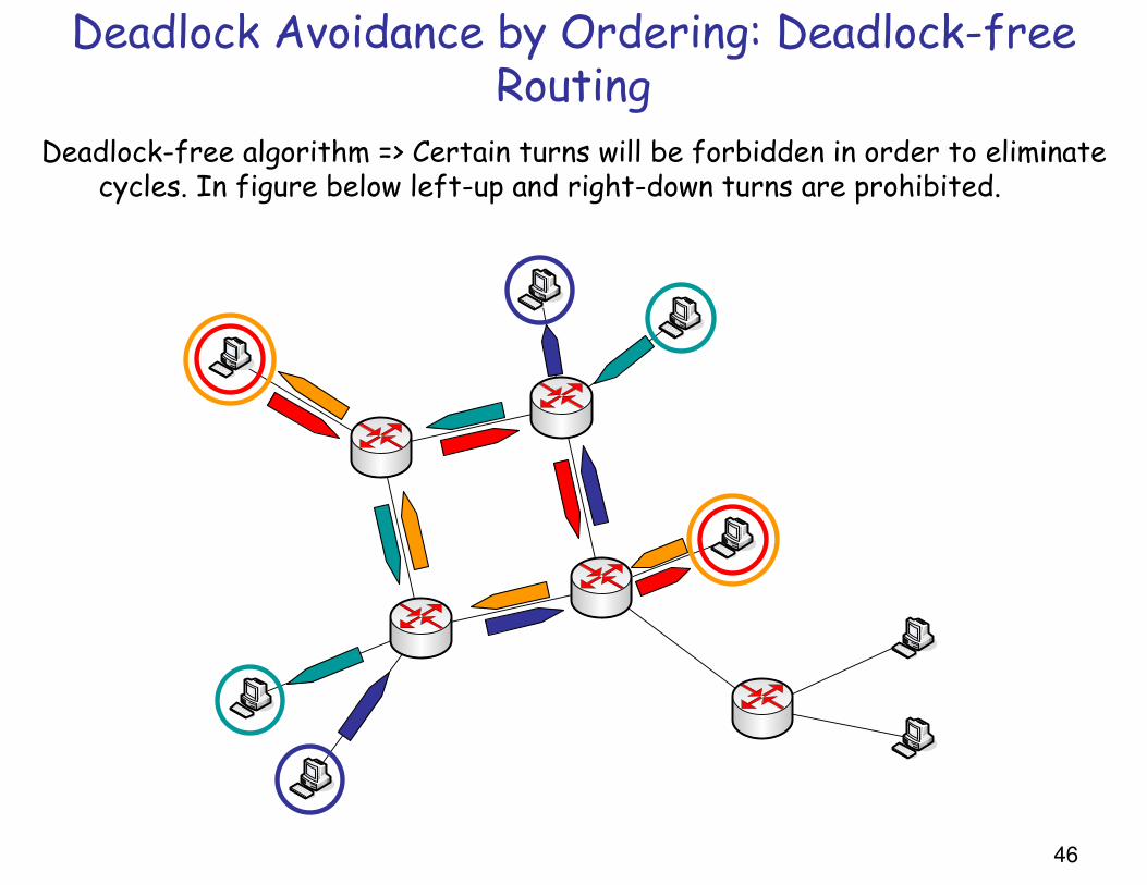
Deadlock Avoidance by Ordering: Deadlock-free Routing
Deadlock-free algorithm => Certain turns will be forbidden in order to eliminate cycles. In figure below left-up and right-down turns are prohibited.

47
1. Split physical links into several VCs 2. Define the restrictions / ordering rules in the use of VCs to avoid / recover
from deadlocks.=> Enables fully or partially adaptive routing.
Deadlock Avoidance or Recovery: Virtual Channels