floset gel injection guidelines - snf
TRANSCRIPT
FLOSET GEL
Injection Guidelines
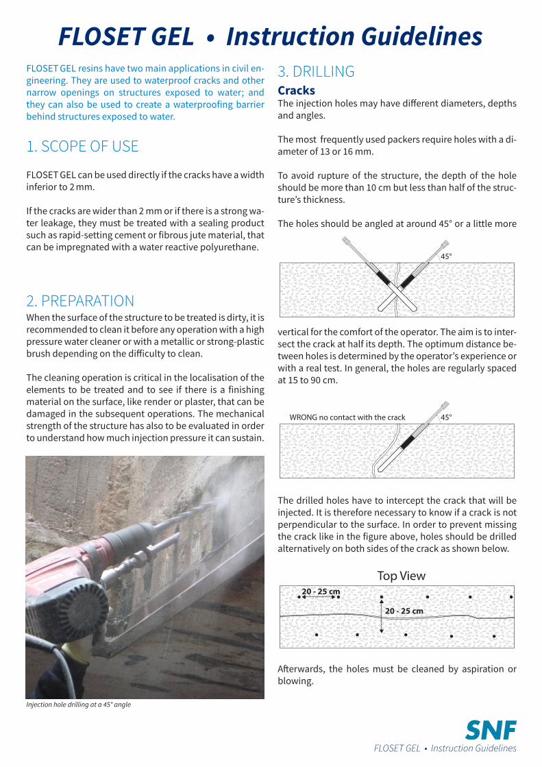
FLOSET GEL resins have two main applications in civil en-gineering. They are used to waterproof cracks and other narrow openings on structures exposed to water; and they can also be used to create a waterproofing barrier behind structures exposed to water.
1. SCOPE OF USE
FLOSET GEL can be used directly if the cracks have a width inferior to 2 mm.
If the cracks are wider than 2 mm or if there is a strong wa-ter leakage, they must be treated with a sealing product such as rapid-setting cement or fibrous jute material, that can be impregnated with a water reactive polyurethane.
2. PREPARATIONWhen the surface of the structure to be treated is dirty, it is recommended to clean it before any operation with a high pressure water cleaner or with a metallic or strong-plastic brush depending on the difficulty to clean.
The cleaning operation is critical in the localisation of the elements to be treated and to see if there is a finishing material on the surface, like render or plaster, that can be damaged in the subsequent operations. The mechanical strength of the structure has also to be evaluated in order to understand how much injection pressure it can sustain.
Injection hole drilling at a 45° angle
3. DRILLINGCracksThe injection holes may have different diameters, depths and angles.
The most frequently used packers require holes with a di-ameter of 13 or 16 mm.
To avoid rupture of the structure, the depth of the hole should be more than 10 cm but less than half of the struc-ture’s thickness.
The holes should be angled at around 45° or a little more
vertical for the comfort of the operator. The aim is to inter-sect the crack at half its depth. The optimum distance be-tween holes is determined by the operator’s experience or with a real test. In general, the holes are regularly spaced at 15 to 90 cm.
The drilled holes have to intercept the crack that will be injected. It is therefore necessary to know if a crack is not perpendicular to the surface. In order to prevent missing the crack like in the figure above, holes should be drilled alternatively on both sides of the crack as shown below.
Afterwards, the holes must be cleaned by aspiration or blowing.
45°WRONG no contact with the crack
Top View20 - 25 cm
20 - 25 cm
45°
FLOSET GEL • Instruction Guidelines
FLOSET GEL • Instruction Guidelines
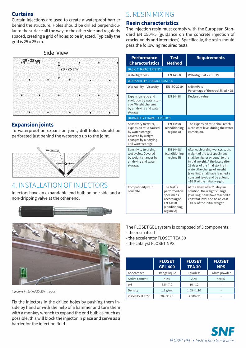
CurtainsCurtain injections are used to create a waterproof barrier behind the structure. Holes should be drilled perpendicu-lar to the surface all the way to the other side and regularly spaced, creating a grid of holes to be injected. Typically the grid is 25 x 25 cm.
Expansion jointsTo waterproof an expansion joint, drill holes should be perforated just behind the waterstop up to the joint.
4. INSTALLATION OF INJECTORSInjectors have an expandable end bulb on one side and a non-dripping valve at the other end.
Injectors installed 20-25 cm apart
Fix the injectors in the drilled holes by pushing them in-side by hand or with the help of a hammer and turn them with a monkey wrench to expand the end bulb as much as possible, this will block the injector in place and serve as a barrier for the injection fluid.
5. RESIN MIXINGResin characteristicsThe injection resin must comply with the European Stan-dard EN 1504-5 (guidance on the concrete injection of cracks, voids and interstices). Specifically, the resin should pass the following required tests.
Performance Characteristics
Test Method
Requirements
BASIC CHARACTERISTICS
Watertightness EN 14068 Watertight at 2 x 10⁵ Pa
WORKABILITY CHARACTERISTICS
Workability – Viscosity EN ISO 3219 ≤ 60 mPa•sPercentage of the crack filled > 95
Expansion ratio and evolution by water stor-age. Weight changes by air drying and water storage
EN 14498 Declared value
DURABILITY CHARACTERISTICS
Sensitivity to water, expansion ratio caused by water storage.Covered by weight changes by air drying and water storage
EN 14498 (conditioning
regime A)
The expansion ratio shall reach a constant level during the water immersion.
Sensitivity to drying wet cycles. Covered by weight changes by air drying and water storage.
EN 14498(conditioning
regime B)
After each drying-wet cycle, the weight of the test specimens shall be higher or equal to the initial weight. A the latest after 28 days of the final storing in water, the change of weight (swelling) shall have reached a constant level, and be at least +10 % of the initial weight.
Compatibility with concrete
The test is performed on specimens according to EN 14498, (conditioning regime A)
At the latest after 28 days in solution, the weight change (swelling) shall have reached a constant level and be at least +10 % of the initial weight.
The FLOSET GEL system is composed of 3 components:- the resin itself- the accelerator FLOSET TEA 30- the catalyst FLOSET NPS
FLOSET GEL 400
FLOSET TEA 30
FLOSET NPS
Appearance Orange liquid Colorless White powder
Active content 42% 29% > 99%
pH 6.5 - 7.0 10 - 12 -
Density 1.2 g/ml 1.05 - 1.10 -
Viscosity at 20°C 20 - 30 cP < 300 cP -
Side View20 - 25 cm
20 - 25 cm
Waterstop
FLOSET GEL • Instruction Guidelines
Mixing procedureJust prior to the injection operations, 2 solutions have to be prepared.
Solution A = resin + accelerator (TEA)Solution B = catalyst in water (NPS)
The indicative doses of accelerator and catalyst are listed in the table below. The gelling time will depend on tem-perature and dilution. It is always a good practice to con-trol the setting time before doing the injection and adjust the accelerator dosage if necessary.
The preparation should be injected within 2 hours.T °C FLOSET
GEL 400 (kg)FLOSET
TEA 30 (kg)FLOSET NPS (g*)
GellingTime
21 20 0.42 500 6 ‘
21 20 0.84 500 1 ‘
21 20 1.26 500 45 “
21 20 2.10 500 25 “
10 20 0.84 700 3,5 ‘
10 20 1.68 700 1,5 ‘
10 20 2.52 700 1 ‘
* g/20 L water
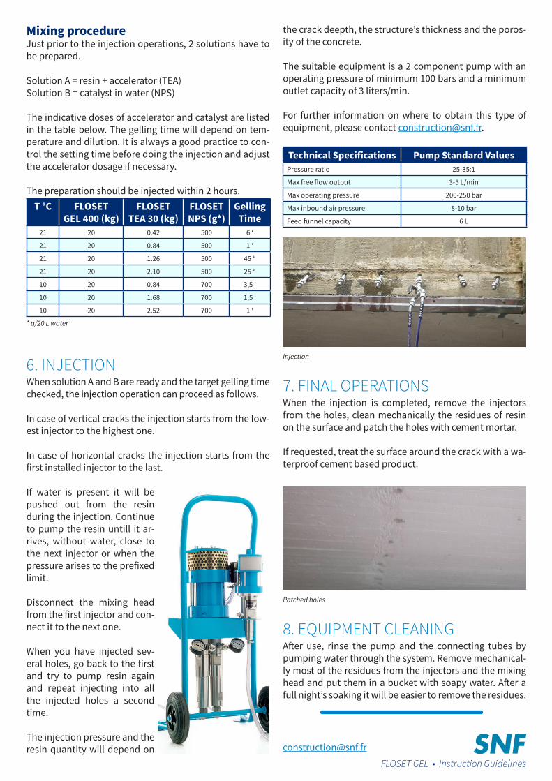
6. INJECTIONWhen solution A and B are ready and the target gelling time checked, the injection operation can proceed as follows.
In case of vertical cracks the injection starts from the low-est injector to the highest one.
In case of horizontal cracks the injection starts from the first installed injector to the last.
If water is present it will be pushed out from the resin during the injection. Continue to pump the resin untill it ar-rives, without water, close to the next injector or when the pressure arises to the prefixed limit.
Disconnect the mixing head from the first injector and con-nect it to the next one.
When you have injected sev-eral holes, go back to the first and try to pump resin again and repeat injecting into all the injected holes a second time.
The injection pressure and the resin quantity will depend on
the crack deepth, the structure’s thickness and the poros-ity of the concrete.
The suitable equipment is a 2 component pump with an operating pressure of minimum 100 bars and a minimum outlet capacity of 3 liters/min.
For further information on where to obtain this type of equipment, please contact [email protected].
Technical Specifications Pump Standard ValuesPressure ratio 25-35:1
Max free flow output 3-5 L/min
Max operating pressure 200-250 bar
Max inbound air pressure 8-10 bar
Feed funnel capacity 6 L
Injection
7. FINAL OPERATIONSWhen the injection is completed, remove the injectors from the holes, clean mechanically the residues of resin on the surface and patch the holes with cement mortar.
If requested, treat the surface around the crack with a wa-terproof cement based product.
Patched holes
8. EQUIPMENT CLEANINGAfter use, rinse the pump and the connecting tubes by pumping water through the system. Remove mechanical-ly most of the residues from the injectors and the mixing head and put them in a bucket with soapy water. After a full night’s soaking it will be easier to remove the residues.
[email protected] GEL • Instruction Guidelines
SNF sasZAC de Milieux
rue Adrienne Bolland42163 Andrézieux Cedex
FRANCE
+ 33 (0)4 77 36 86 [email protected]
SNF HOLDING Co.PO Box 250
1 Chemical Plant roadRiceboro, Georgia 31323
UNITED-STATES
+1 (912) 884 [email protected]
SNF (CHINA) FLOCCULANT Co. Ltd.Taixing economic development zone
West of Tongjiang roadTaixing City Jiangsu Province 225442
CHINA
+86 523 767 [email protected]
www.snfchina.com
All
right
s res
erve
d - P
ublis
hing
: SN
F sa
s - M
arch
201
6
While SNF makes reasonable efforts to ensure the information is accurate and up-to-date, SNF makes no warranties or representations, express or implied, as to the accuracy, completeness, or any other aspect of the information on this document and assumes no liability in connection with any use of this information. Nothing herein shall be construed as a recommendation or license to use any information found that conflicts with any patent, trademark or copyright of SNF or others, and SNF makes no representations or warranties, express or implied that any use of this
information will not infringe any such patent, trademark or copyright
10-31-1247