floating production units - cloudapp.netkrsusa.cloudapp.net/files/krrules/krrules2016/data/... ·...
TRANSCRIPT
2015
Guidance for
Floating Production Units
GC-11-E KR
- i -
APPLICATION OF
"GUIDANCE FOR FLOATING PRODUCTION UNITS"
1. Unless expressly specified otherwise, the requirements in the Guidance apply to Floating
Production Units for which contracts for construction are signed on or after 7 July 2015.
2. The amendments to the Rules for 2014 edition and their effective date are as follows;
Effective Date 1 July 2015
CHAPTER 1 GENERAL
Section 1 General
- 103. has been amended.
CHAPTER 2 CLASSIFICATION AND SURVEYS
Section 2 Classification
- 204.6 has been amended.
- 204.7 has been newly added.
CHAPTER 8 FIRE PROTECTION, MEANS OF ESCAPE AND FIRE EXTINCTION
Section 1 General
- 101.2 has been amended.
Section 2 Prevention of Fire and Explosion
- 201. has been amended.
Section 3 Suppression of Fire
- 302.6 and 7 have been deleted. (moved to Ch 11, Sec 2.)
CHAPTER 10 ELECTRICAL EQUIPMENT AND CONTROL SYSTEMS
Section 2 Control Systems
- 207. has newly added. (moved from Ch 8, 302.)
- 208. has been amended.
- ii -
CHAPTER 11 PRODUCTION AND PROCESS SYSTEMS
Section 2 Design of Process Systems
- 202. has been deleted. (moved to Ch 8, 201.)
CHAPTER 12 IMPORT AND EXPORT SYSTEMS
Section 1 General
- 105.2 has newly added. (moved from Ch 2, 204.6)
- iii -
CONTENTS
CHAPTER 1 GENERAL ······································································································· 1
Section 1 General ··············································································································· 1
Section 2 Definition ············································································································ 2
CHAPTER 2 CLASSIFICATION AND SURVEYS ·························································· 3
Section 1 General ··············································································································· 3
Section 2 Classification ···································································································· 3
Section 3 Surveys ··············································································································· 8
CHAPTER 3 DESIGN CONDITIONS ·············································································· 29
Section 1 General ············································································································· 29
Section 2 Design Principles ··························································································· 29
Section 3 Corrosion Control Means and Corrosion Margins ········································ 31
Section 4 Design Loads ··································································································· 32
CHAPTER 4 MATERIALS AND WELDING ··································································· 37
Section 1 General ············································································································· 37
CHAPTER 5 HULL CONSTRUCTION AND EQUIPMENT ········································ 39
Section 1 General ············································································································· 39
Section 2 Stability ············································································································· 40
Section 3 Longitudinal Strength ······················································································· 40
Section 4 Structural Design and Analysis of the Hull ·················································· 42
Section 5 Design and Analysis of Other Major Hull Structural Features ················· 46
Section 6 Structural Strength for Column-stabilized and Other Type Units ················ 52
Section 7 Hull Equipment ································································································ 52
CHAPTER 6 POSITIONING SYSTEMS ········································································· 53
Section 1 General ············································································································· 53
Section 2 Mooring Analysis ····························································································· 54
Section 3 Design of Mooring Lines, etc. ······································································· 58
Section 4 Mooring Equipment ························································································· 60
Section 5 Single Point Mooring Systems ······································································· 61
Section 6 Anchor Holding Power ···················································································· 63
Section 7 Dynamic Positioning Systems ········································································· 65
CHAPTER 7 HAZARDOUS AREA ··················································································· 67
Section 1 General ············································································································· 67
Section 2 Extent of Hazardous Area ·············································································· 68
Section 3 Ventilation ········································································································ 69
- iv -
CHAPTER 8 FIRE PROTECTION, MEANS OF ESCAPE AND
FIRE EXTINCTION ····················································································· 71
Section 1 General ············································································································· 71
Section 2 Prevention of Fire and Explosion ·································································· 71
Section 3 Suppression of Fire ························································································· 74
Section 4 Means of Escape ····························································································· 82
CHAPTER 9 MACHINERY INSTALLATIONS ······························································· 83
Section 1 General ············································································································· 83
Section 2 Piping Systems for Crude Oil Tanks ····························································· 83
Section 3 Use of Produced Gas as Fuel ········································································ 83
Section 4 Boilers Using Crude Oil ················································································· 84
CHAPTER 10 ELECTRICAL EQUIPMENT AND CONTROL SYSTEMS ··············· 87
Section 1 Electrical Equipment ························································································ 87
Section 2 Control Systems ······························································································· 94
CHAPTER 11 PRODUCTION AND PROCESS SYSTEMS ···································· 101
Section 1 General ··········································································································· 101
Section 2 Design of Process Systems ··········································································· 107
Section 3 Process System Equipment ············································································ 110
Section 4 Process Support Systems ··············································································· 112
CHAPTER 12 IMPORT AND EXPORT SYSTEMS ··················································· 115
Section 1 General ··········································································································· 115
Section 2 Design ············································································································· 116
Ch 1 General Ch 1
Guidance for Floating Production Units 2015 1
CHAPTER 1 GENERAL
Section 1 General
101. Application
1. The requirements in the Guidance are to be applied to the surveys, hull construction, equipment and machinery of floating production units. Floating production units(hereinafter referred to as "units" in the Guidance) as used herein mean units or vessels, not intended for the transport of cargo, which are positioned at a specific site of the installation permanently or for long periods and fitted with systems for the processing, storage and offloading of produced crude oil and petro-leum gases.
2. Attention is to be paid to plied to the International Conventions and National Regulations of the coastal state in which the unit is located during operation, and statutory requirements of the International Conventions and the National Authority may be stricter than requirements of this Guidance.
102. Classification of units
Units to which this guidance apply are classified as followings;
1. Purpose of units
(1) FPSO (Floating Production, Storage and Offloading)
FPSO is a unit with systems for the processing, storage and offloading of produced crude oil and petroleum gases.
(2) FPO (Floating Production and Offloading)
FPO is a unit with systems for the processing and offloading of produced crude oil and petro-leum gases.
(3) FSO (Floating Production and Storage)
FSO is a unit with systems for the storage and offloading of produced crude oil and petroleum gases.
2. Type of units
(1) Ship type Ship type is the unit in the shape of an ordinary tanker or cargo ship having displacement hull.(2) Column-stabilized type Column-stabilized type is a unit consisting of deck with top-side installations, surface piercing
columns, submerged lower hulls, bracings, etc., which are semi-submerged to a predetermined draft during operation.
(3) Tension Leg Platform (TLP) TLP is a unit which fully buoyant and is restrained below its natural flotation line by mooring
elements which are attached in tension to gravity anchors or piles at the sea floor.(4) Spar Spar is a unit which is deep draft, vertical floating structures, usually of cylindrical shape, sup-
porting a topside deck and moored to the seafloor. The hull can be divided into upper hull, mid-section and lower hull.
(5) There may be other types of units, which are not specified in (1) to (4) above, such as cylin-drical type.
103. Equivalence and novel features
1. The Society may consider the acceptance of alternatives to the Guidance, provided that they are deemed to be equivalent to the Guidance to the satisfaction to the Society.
2. The Society may consider the classification of the construction and equipment based on or applying novel design principles or features, to which the Rules are not directly applicable, on the basis of experiments, calculations or other supporting information provided to the Society.
Ch 1 General Ch 1
2 Guidance for Floating Production Units 2015
3. The risk evaluation may be applicable for justification of equivalence or novel features.
Section 2 Definition
201. Application
The definitions of terms and symbols which appear in the Guidance are to be as specified in this Section, unless otherwise specified, and definitions of terms and symbols not specified in the Guidance are to be as specified in Rules for the Classification of Steel Ships and Rules for the Classification of Mobile Offshore Drilling Units.
202. Definition
1. Production systems are systems for processing (separation of contaminants such as water, sand, etc., and degassing) crude oils, etc. drawn up from the seabed, which generally consists of process-ing systems, safety/control systems and process support systems.
2. Process systems are systems for the separation of contaminants such as water, sand, etc., the separation of salt content, sulphur compounds, etc. of the crude oils, etc. drawn up from the sea-bed, and the removal of water from separated gases, which generally consist of crude oil process-ing systems, water processing systems and gas processing systems.
3. Process support systems are systems to support the drawing up and processing of crude oils, etc., which includes power generation and distribution systems, instrument and service air systems, potable water systems, fuel oil systems, instrument systems, communication systems, fire fighting systems, etc.
4. Positioning systems are such systems to keep the unit at a specific position of designated serv-ice area permanently or for long periods of time, which are specified in the followings(1) Spread mooring systems consist of mooring lines connected to piles, sinkers, etc., which are
firmly embedded into the seabed, the other end of which is individually connected to winches, or stoppers which are installed on a unit, the definitions of each category being as given in the followings.(A) Catenary Mooring(CM) is defined as mooring forces obtained mainly from the net weight
of spreaded catenary mooring lines.(B) Taut Mooring(TM) is defined as mooring lines arranged straight and adjusted by high ini-
tial mooring forces, and the mooring forces obtained from the elastic elongation of these lines.
(2) Single point mooring system (SPM) is a system that allows a unit to weathervane so that the unit changes its heading corresponding to wind and wave directions. Typical SPM systems are as shown below:(A) Catenary Anchor Leg Mooring (CALM) consists of a large buoy connected to mooring
points at the seabed by catenary mooring lines. The unit is moored to the buoy by mooring lines or a rigid yoke structure.
(B) Single Anchor Leg Mooring (SALM) consists of the mooring structure with buoyancy which is positioned at or near the water surface, and is connected to the seabed. The unit is moored to the buoy by mooring lines or a rigid yoke structure.
(C) Turret mooring allows only unit's angular movement relative to the turret so that it may be weathervane. The turret may be fitted internally within the unit, or externally at the stern/bow of the unit. The turret is generally connected to the seabed using a spread moor-ing system.
5. Crude Oil Spaces mean spaces used for the storage of crude oil (including crude oil tanks), and the trunks leading to such spaces.
6. Crude Oil Areas mean crude oil tanks, slop tanks, crude oil pump rooms, and adjacent pump rooms, cofferdams, ballast space or void spaces to crude oil tanks as well as the deck areas above these spaces covering all of the length and breadth of the unit.
7. Production Areas mean the areas where production systems are installed.
Ch 2 Classification and Surveys Ch 2
Guidance for Floating Production Units 2015 3
CHAPTER 2 CLASSIFICATION AND SURVEYS
Section 1 General
101. General
1. The classification and surveys of units intended to be classed with the Society or classed with the Society are to be in accordance with the requirements specified in this Chapter.
2. In the case of items not specified in this Chapter, the requirements specified in Pt 1 of Rules for the Classification of Steel Ships are to be applied.
Section 2 Classification
201. Classification
Units built and surveyed for the classification in accordance with this Guidance or in accordance with requirements deemed to be equivalent to this Guidance by the Society will be assigned a class and registered in the Register of Ships.
202. Class notations
1. The class will be distinguished by the class notations and the class notations assigned to the unit classed with the Society are to be in accordance with the requirements specified in Pt 1, Ch 1, 201. of Rules for the Classification of Steel Ships. However, the ship type notation and spe-cial feature notation shall be assigned as followings.(1) The following ship type notation shall be assigned according to the purpose of unit.
(A) Floating Production, Storage and Offloading Unit(B) Floating Production and Offloading Unit(C) Floating Storage and Offloading Unit
(2) The following special feature notations shall be assigned according to the type of unit.(A) Ship Type(B) Barge Type(C) Column-stabilized(D) Spar(E) TLP
2. When an existing vessel is converted to an unit, and is classed with the Society according to the requirements of this Guidance, the notation (C) shall be assigned as special feature notation. If the existing vessel being converted is currently classed with the Society with ✠ symbol, then the ✠ symbol would be maintained for the converted unit.
3. At the request of the Owner, the special feature notations may be assigned as followings.(1) For units fitted with the production systems, where the whole production systems are in com-
pliance with Ch 11, the notation Production may be assigned additionally. However, for units fitted with the production systems, even if the production systems are not intended to be classed, the devices related to the safety of the production systems are to be comply with the requirements of Ch 8 and Ch 11.
(2) Where the import and/or export systems are in compliance with the requirements of Ch 12, the notation Import and/or Export may be assigned additionally.
(3) For the unit that has a propulsion system and a means of disengaging the unit from its moor-ing and riser systems, the notation Disconnectable may be assigned additionally.
203. Maintenance of classification
1. Units classed with the Society are to be subjected to the surveys to maintain the classification and are to be maintained in good condition in accordance with the requirements specified in this Chapter.
2. Plans and particulars of any proposed alterations to the approved scantlings or arrangements of hull,
Ch 2 Classification and Surveys Ch 2
4 Guidance for Floating Production Units 2015
machinery or equipment are to be submitted for approval by the Society before the work is com-menced and such alterations are to be surveyed by the Surveyor of the Society.
204. Classification Survey during Construction
1. General
At the Classification Survey during Construction, the hull, machinery and equipment are to be ex-amined in detail in order to ascertain that they meet the relevant requirements of this Guidance.
2. Submission of plans and documents
(1) At the Classification Survey during Construction, the following plans and documents are to be submitted to the Society for approval before the work is commenced.(A) Hull and hull equipments
(a) Transverse section showing scantlings(b) Longitudinal section showing scantlings(c) Deck construction plan(including details of well and helicopter deck)(d) Framing(e) Shell expansion(f) Final stability data(g) Methods and locations for non-destructive testing(h) Construction plan of watertight bulkheads and deep tanks indicating the highest position
of tank and positions of tops of overflow pipes(i) Construction of superstructures and deckhouses(j) Details of arrangement and closing devices of watertight doors and hatchways, etc.(k) Seatings of boilers, main engines, thrust blocks, plummer blocks, dynamos and other im-
portant auxiliary machinery(l) Construction of machinery casings(m) Construction of cargo handling appliances and its foundation(n) Pumping arrangements(o) Steering gear(p) Construction of fire protection(q) Means of escape(r) Temporary mooring arrangements and towing arrangements(s) Welding details and procedures(t) Details of corrosion control arrangements(u) Documents in respect of maintenance, corrosion control and inspection(v) Other plans and/or documents considered necessary by the Society
(B) Machinery(a) Plans and data relevant to machinery installation specified in Pt 5, Ch 1, Sec 2 of Rules for the Classification of Steel Ships.
(b) Electrical installations specified in Pt 6, Ch 1 of Rules for the Classification of Steel Ships, and automatic and remote control system specified in Pt 6, Ch 2 of Rules for the Classification of Steel Ships.
(c) Fire extinguishing arrangements and inert gas system(d) Other plans and/or documents considered necessary by the Society
(C) Production systemsFor the unit with notation Production, submission of plans and documents for the pro-duction system is to in accordance with Ch 11.
(D) Import and Export systemsFor the unit with notation Import and/or Export, submission of plans and documents for the import and export system is to in accordance with Ch 12.
(2) At the Classification Survey during Construction, the following plans and documents are to be submitted to the Society for reference.(A) Specifications(B) General arrangement(C) Summary of distributions of fixed and variable weights(D) Plan indicating design loadings for all decks(E) Preliminary stability data
Ch 2 Classification and Surveys Ch 2
Guidance for Floating Production Units 2015 5
(F) Structural analysis and calculation for relevant loading conditions(G) Resultant forces and moments from wind, waves, current, mooring and other environmental
loadings taken into account in the structural analysis(H) Calculations for significant operational loads from derrick and other equipment(I) Lines or offsets(J) Capacity plans and sounding tables of tanks(K) Plans showing arrangement of watertight compartments, openings, their closing appliances,
etc., necessary for calculation of stability(L) Other plans and/or documents considered necessary by the Society
Submitted calculations are to be suitably referenced. Results from relevant model tests or dynamic response calculations may be submitted as alternatives or as substantiation for the required calculations.
3. Presence of Surveyor
(1) At the Classification Survey during Construction, the presence of the Surveyor is required at the following stages of the work in relation to hull and equipment.(A) When the tests of the materials specified in Pt 2, Ch 1 of Rules for the Classification of Steel Ships and the equipment specified in Pt 4 of Rules for the Classification of Steel Ships are carried out.
(B) When the tests of welding specified in Pt 2, Ch 2 of Rules for the Classification of Steel Ships are carried out.
(C) When designated by the Society during shop work or sub-assembly.(D) When each block is assembled and erected.(E) When each part of the hull is completed.(F) When structural tests, leak test, hose tests and non-destructive tests are carried out.(G) When performance tests are carried out on closing appliances of openings, anchoring and
mooring equipment, cargo handling appliances, fire detection systems, etc.(H) When each part of the fire protection construction is completed.(I) When measurement of principal dimensions, hull deflection, etc. are carried out.(J) When a loading instrument is installed on board.(K) When the load line mark is marked.(L) When the onboard tests and stability experiments are carried out.(M)When deemed necessary by the Society.
(2) At the Classification Survey during Construction, the presence of the Surveyor is required at the following stages of the work in relation to machinery.(A) When the tests of materials of main parts of machinery specified in Pt 2 of Rules for the Classification of Steel Ships are carried out.
(B) Main parts of machinery(a) When the tests specified in either Pt 5 or Pt 6 of Rules for the Classification of Steel Ships according to the kind of machinery are carried out.
(b) When the materials are assembled for construction of the parts and the parts are as-sembled for installation on board.
(c) When machining of the main parts is finished and, if necessary, at appropriate stages during machining.
(d) In case of welded construction, before welding is commenced and when it is completed.(e) When the shop trials are carried out.
(C) When main parts of machinery are installed on board.(D) When performance tests/onboard tests are carried out on measurement instruments, remote
control devices of closing appliances, remote control devices for machinery and gears, auto-matic control devices, steering gear, mooring equipment, fire extinguishing equipments, pip-ing, etc.
(E) When deemed necessary by the Society.
4. Tests
(1) At the Classification Survey during Construction, hydrostatic tests, leak tests, hose tests and per-formance tests, etc are to be carried out in accordance with the relevant requirements of this Guidance.
(2) In the case of machinery and electrical installations related to production systems and the pipes and hoses installed on units during off loading, hydrostatic tests, leak tests or airtight tests are to be carried out as specified in this Guidance corresponding to the kind of machinery and
Ch 2 Classification and Surveys Ch 2
6 Guidance for Floating Production Units 2015
electrical installations.(3) In case where production systems or positioning systems, etc. are installed on board units at
works different from the shipbuilding yards where hull structures are constructed (including the sea areas of the site of operation), surveys necessary in order to tow the hull structures of units to their site of operation are to be carried out. In this cases, the tests, examinations or in-spections for the support structures of installations are to be carried out at suitable places/occa-sions before the final inspection at the site of operation.
(4) Equipments which cannot be surveyed at the Classification Survey during Construction due to special reasons that are related to such equipment only being capable of functioning after start-up and commissioning are to be identified for verification at the next Annual Survey.
5. Survey for storage facilities
In case of the equipment found in storage facilities(piping systems for crude oil, crude oil pumps, venting systems, inert gas systems, etc.), tests and surveys are to be carried out in accordance with the requirements for the cargo oil systems of tankers specified in Pt 5 and Pt 7, Ch 1 of Rules for the Classification of Steel Ships as applicable.
6. Survey for production systems(if relevant notations are assigned)
Survey for production systems is to be in accordance with the requirements specified in Ch 11.
7. Survey for import and export systems(if relevant notations are assigned)
Survey for import and export systems is to be in accordance with the requirements specified in Ch 12.
8. Survey during the installation of units at their site of operation
(1) During the installation of positioning systems, the following items are to be verified and sur-veyed by the Surveyor.(A) The components of positioning systems are to be examined for abnormalities before
installation.(B) Certificates are to be confirmed for those components which are required to be tested at
manufacturer facilities.(C) The area around the seabed mooring points is to be examined and reported on by divers or
remotely operated vehicles(ROVs) before installation to ensure that there is no obstruction.(D) During the installation of units to their seabed mooring points, the following is to be
verified.(a) Proper locking of all connecting shackles from mooring lines to seabed mooring points,
and from mooring lines to mooring lines(b) Sealing of all kenter shackle locking pins(c) Correct size and length of all the components of mooring lines(d) Whether seabed mooring points are installed in their designed position and are orientated
within allowable design tolerance.(E) Mooring lines are to be confirmed to be paid out as designed and in accordance with pre-
determined procedures.(F) After mooring systems are deployed at their site of operation, the following tests are re-
quired for each mooring line.(a) During tests, each mooring line is to be pulled to its maximum design load determined
by dynamic analysis for the intact design condition and held at that load for 30 minutes. The integrity of the entire mooring line from the seabed mooring point to the connecting end at the hull structure of the unit as well as movement of the seabed mooring point is to be verified.
(b) Notwithstanding (a) above, the test load for soft clay may be modified as deemed ap-propriate by the Society. Even in such cased, however, test loads cannot be reduced less than 80% of the maximum intact design loads.
(c) Notwithstanding (a) and (b) above, the tensioning tests of mooring lines may be waived in cases where detailed investigation reports are submitted to the Society and deemed appropriate. In such cases, however, preloading each seabed mooring point in required. The load of this preloading is not to be less than the mean intact design tension, and such that the integrity and proper alignment of mooring lines can be verified.
(G) Mooring lines are to be verified for firm and adequate connections to chain stoppers.(H) It is to be verified that the relative position of the single point mooring center of single
Ch 2 Classification and Surveys Ch 2
Guidance for Floating Production Units 2015 7
point mooring systems to pipe line end manifolds(PLEMs) is in compliance with design specifications and tolerances.
(I) Catenary angles of mooring lines are to be measured and verified for compliance with de-sign specifications and tolerances.
(J) During installation, it is to be verified that the risers and other supporting facilities of units are not deformed or damaged, buoyancy tanks, etc. are in their correct position, and flow lines are firmly and adequately connected.
(K) Upon completion of installation, the connection of units to their periphery facilities is to be verified for compliance with design specifications. Divers or ROVs are to be arranged as necessary for the survey of any underwater parts deemed necessary by the Surveyors.
9. Onboard tests and stability experiments
(1) During the onboard tests of units, the following items are to be verified and surveyed by the Surveyor. The results of onboard tests are to be submitted to the Society.(A) Performance tests of positioning systems(performance tests of windlass, etc.)(B) Performance tests of such systems that are necessary for adjusting the draught, inclination,
etc. of units, like ballasting systems(C) Running tests of machinery and electrical installations, etc.(during their operation, no abnor-
malities in the condition of units are found)(D) The accumulation tests of boilers(E) Confirmation of safety systems(fire/gas detection systems, fire extinguishing system, emer-
gency shutdown systems)(F) Function test of communication systems(G) Emergency procedures against oil spill, fires, etc.(H) Confirmation of fire extinguishing system
(a) Fire pumps(b) Fixed fire-extinguishing systems(c) Portable fire extinguishers
(I) Function tests of detection and alarm systems(a) Fire detection systems(b) Gas detection systems(c) Control panels of fire/gas detection systems(d) Emergency shutdown systems
(J) Confirmation that all systems of the unit are functioning normally(K) Confirmation of production systems(controlling system, emergency shutdown, etc.)(L) Confirmation of purging capability(M) Confirmation of flare systemsHowever, if the items specified above are verified by simulating installed conditions at ship-building yards, such onboard tests may be dispensed with.
(2) Stability experiments are to be carried out at suitable occasions after the completion of the main structures of units and before proceeding to the site of operation. A stability information booklet prepared on the basis of the stability particulars determined by the results of stability experiments is to be approved by the Society and provided on board.
205. Classification Survey after Construction
1. General
At the Classification Survey after Construction, the examination of the hull, machinery and equip-ment are carried out as required for the Special Survey corresponding to the age, kind and purpose of the unit and the actual scantlings, etc. of the main parts of the unit are to be measured as necessary.
2. Submission of plans and documents
At the Classification Survey after Construction, plans and documents as may be required for the Classification Survey during Construction are to be submitted. If plans and documents cannot be obtained, facilities are to be given for the Surveyor to take the necessary information from the unit.
3. Onboard tests and stability experiments
At the Classification Survey after Construction, onboard tests and stability experiments are to be carried out in accordance with the requirements specified in 204. 9. However, onboard tests and
Ch 2 Classification and Surveys Ch 2
8 Guidance for Floating Production Units 2015
stability experiments may be dispensed with provided that sufficient information based on previous tests is available and neither alteration nor repair affecting onboard tests and stability experiments has been made after such previous tests.
Section 3 Surveys
301. General
1. Units classed with the Society are to be subjected to the following surveys to maintain the classification.(1) Special Surveys(2) Intermediate Surveys(3) Annual Surveys(4) Docking Surveys(5) Surveys of Propeller Shaft and Stern Tube Shaft, Etc.(6) Boiler Surveys(7) Continuous Surveys(8) Alteration Survey(9) Occasional Surveys
2. Damage, failure and repair
(1) ExaminationDamage, failure, deterioration or repair to the unit or its elements which affects or may affects classification is to be submitted by the Owners or their representatives for examination by the Surveyor.
(2) Repairs Where repairs to the unit or its elements which may affect classification are planned in ad-
vance, a complete repair procedure, including the extent of the proposed repair and the need for the Surveyor's attendance, is to be submitted to and agreed upon by the Surveyor reasonably in advance. Failure to notify the Society in advance of the repairs may result in suspension of the unit's classification until such time as the repair is redone or evidence is submitted to satisfy the Surveyor that the repair was properly carried out.
Note : The above applies also to repairs during voyage or on site.
The above is not intended to include maintenance and overhaul to hull, machinery and equip-ment in accordance with manufacturer's recommended procedures and established marine practice and which does not require the approval of the Society. However, any repairs as a result of such maintenance and overhauls which affects or may affect classification is to be noted in the unit's log and submitted to the Surveyors for use in determining further survey requirements as required by (1) above. All repairs found necessary by the Surveyor are to be completed to the Surveyor's satisfaction.
3. Continuous Surveys
(1) At the request of the Owner and upon the Society's approval of the proposed arrangements, a system of Continuous Surveys may be undertaken whereby the Special Survey requirements are carried out in regular rotation to complete all of the requirements of the particular Special Survey within a 5-year period. Each part(item) surveyed becomes due again for survey approx-imately five(5) years from the date of survey. The due parts(items) are generally to be com-pleted each year. Continuous items that are three(3) months or more overdue at the time of Annual Survey attendance will be basis for the Annual Survey not to be credited and for non-endorsement of the Certificate of Classification. Consideration may be given by the Society to an extension to complete survey items. If any defects are found during the survey, they are to be dealt with to the satisfaction of the Surveyor.
(2) Docking Survey or equivalent In-water Survey, as required by 304., may be performed at any time within the five-year Special Survey period, provided that all requirements of 305. are met and thickness measurements are taken when the unit is surveyed.
Ch 2 Classification and Surveys Ch 2
Guidance for Floating Production Units 2015 9
4. Lay-up and reactivation
(1) The Society is to be notified by the Owner that a unit has been laid-up. The surveys falling due during lay-up may then be held in abeyance until the unit reactivates. Lay-up procedures and arrangements for maintenance of conditions during lay-up may be submitted to the Society for review and verification by survey.
(2) The requirements for surveys on reactivation are to be specially considered in each case, with due regard given to the status of surveys at the time of the commencement of the lay-up peri-od, the length of the period and the conditions under which the unit has been maintained dur-ing that period.
(3) Units returning to active service, regardless of whether the Society has been informed previously that the unit has been in lay-up, will require a Reactivation Survey.
5. Survey Reports File
All survey reports and records of all abnormalities found are to be compiled into the Survey Report File that is to be kept onboard the unit at all times for reference during any survey. The records to be kept include, but are not limited to, the following:
(1) Survey and Inspection Plan(2) The updated status records of all class surveys(3) The records of all abnormalities found that are to include all videos and photographic records(4) The records of all repairs performed on any abnormalities found and any further repetitive ab-
normalities found subsequent to the repairs(5) Records of all corrosion prevention system maintenance, including records of all cathodic poten-
tial readings taken, records of depletion of all sacrificial anodes, impressed current maintenance records, such as voltage and current demands of the system, coating breaks and the monitoring records of the steel material wastage in way of the coating break areas
(6) All classification survey reports pertaining to the unit(7) All records of any findings of abnormalities by the crew personnel onboard, including all lea-
kages in bulkheads and piping(8) Reports of thickness measurements of the unit(9) Reports of all NDE performed
6. Surveys using risk-based techniques
A properly conducted Risk-Based Inspection Plan or Reliability Centered Maintenance Plan may be credited as satisfying requirements of surveys for maintenance of class for the corresponding unit. The application of this requirements does not cover any statutory survey requirements that may ap-ply to the unit being considered. Although the Society is authorized to perform statutory surveys on behalf of some authorities, the Society is not in a position to alter or waive them. The Owner is to ensure that in developing the inspection plan or maintenance plan, due consideration is given to applicable requirements external to the Society.
Ch 2 Classification and Surveys Ch 2
10 Guidance for Floating Production Units 2015
302. Annual Survey
1. Due range
Annual Survey is to be carried out within 3 months before or after each anniversary date.
2. Hull and equipment
(1) All units(ship type) For ship type units, at each Annual Survey, the weather decks, hull plating and their closing
appliances together with watertight penetrations are to be generally examined as far as practi-cable and placed in satisfactory condition. The following documents, as applicable, are to be available onboard during Annual Surveys:
(a) General Arrangement(b) Capacity Plan(c) Hazardous Area Classification Plans(d) List of Electrical Equipment(e) Operations Manual(f) Construction Portfolio(g) Survey Reports File, as required by 301. 5
The survey is to include the following, as applicable:(A) Protection of openings
(a) Hatchways, manholes and scuttles in freeboard and superstructure decks(b) Machinery casings, fiddley covers, funnel annular spaces, skylights, companionways and
deckhouses protecting openings in freeboard or enclosed superstructure decks(c) Portlights together with deadcovers, cargo ports, bow or stern access, chutes and similar
openings in unit's sides or ends below the freeboard deck or in way of enclosed super-structures
(d) Ventilators including closing devices where fitted, air pipes together with flame screens and weld connections to deck plating. All air pipe closure devices installed on the ex-posed decks are to be externally examined, randomly opened out and their condition verified. Scuppers, inlets and overboard discharges are to be externally examined as ac-cessible including their attachment to shell and valves.
(e) Watertight bulkheads, bulkhead penetrations, end bulkheads of enclosed superstructures and the operation of any doors in same
(f) Weathertight doors and closing appliances for all of the above including stiffening, dogs, hinges and gaskets. Proper operation of weathertight doors and closing appliances to be confirmed.
(B) Freeing portsFreeing ports, together with bars, shutters and hinges
(C) Protection of crewGuard rails, lifelines, gangways and deck houses accommodating crew
(D) Loading and stability informationConfirmation of loading manual, stability data and damage control plans, as applicable. Loading instruments installed to supplement the trim and stability booklet are to be con-firmed in working order by use of the approved check conditions, as applicable. The user's instruction manual for the loading instrument is to be confirmed onboard.
(E) Load lineConfirmation that no alterations have been made to the hull or superstructures which would affect the calculation determining the position of the load lines. Record of conditions of as-signment of load lines is to be available onboard for reference. The load line marks are to be sighted, found plainly visible, and remarked and/or painted, as required.
(F) Mooring systems(a) Spread mooring systems The spread mooring system is to be generally examined so far as can be seen and
placed in satisfactory condition as necessary. In addition, the following above water items are to be examined, placed in satisfactory condition and reported upon, where ap-plicable:(i) The anchor chain stopper structural arrangements are to be visually examined, in-
cluding the structural foundations of all of the stoppers or holders. Tensioning equip-ment is to be generally examined.
Ch 2 Classification and Surveys Ch 2
Guidance for Floating Production Units 2015 11
(ii) The anchor chain's catenary angles are to be measured to verify that the anchor chain tensions are within the design allowable tolerances. Where anchor cables are used, their tensions are to be verified to be within the allowable tensions.
(iii) The anchor chains or anchor cables above the water are to be visually examined for wear and tear.
(b) Single point mooring(SPM) systems The single point mooring system is to be generally examined so far as can be seen
above water and placed in satisfactory condition as necessary. In addition, the following above water items are to be examined, placed in satisfactory condition and reported upon, where applicable:(i) The anchor chain stopper structural arrangements are to be visually examined, in-
cluding the structural foundations of all of the stoppers.(ii) The anchor chain's catenary angles are to be measured to verify that the anchor
chain tensions are within the allowable design tolerances. Where anchor cables are used, their tensions are to be verified to be within the allowable tensions.
(iii) The anchor chains or anchor cables above the water are to be visually examined for wear and tear.
(iv) The condition of the bearings is to be verified for continued effectiveness of the lubrication system.
(v) The entire assembly of the single point mooring structure above water is to be gen-erally examined for damage, coating breaks and excessive signs of corrosion. This survey is to include all turret wall structures, accessible turret well structures, moor-ing arms, all structures supporting the disconnectable operations of the mooring sys-tem, etc., whichever are applicable.
(G) Structural fire protectionVerification that no significant changes have been made to the arrangement of structural fire protection, verification of the operation of manual and/or automatic fire doors, if fitted, and verification that the means for escape from the accommodations, machinery spaces and other spaces are satisfactory.
(H) Suspect areasSuspect areas of the hull are to be overall examined, including an Overall and Close-up Survey of those suspect areas which were identified at the previous surveys. Areas of sub-stantial corrosion identified at previous surveys are to have thickness measurements taken. Where extensive areas of corrosion are found or when considered necessary by the Surveyor, thickness measurements are to be carried out and renewals and/or repairs made when wastage exceeds the allowable margin. Where substantial corrosion is found, additional thickness measurements in accordance with Pt 1, Ch 2, Table 1.2.5 of Rules for the Classification of Steel Ships are to be taken to confirm the extent of substantial corrosion. These extended thickness measurements are to be carried out before the survey is credited as completed. Where reduced scantlings on the basis of effective corrosion pre-vention system have been adopted, the results of any measurements are to be evaluated based on the scantlings before reduction.
Ch 2 Classification and Surveys Ch 2
12 Guidance for Floating Production Units 2015
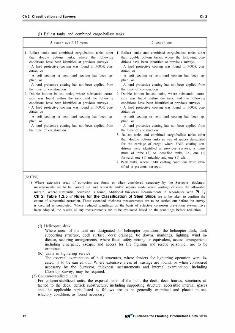
(I) Ballast tanks and combined cargo/ballast tanks
5 years < age ≤ 15 years 15 years < age
1. Ballast tanks and combined cargo/ballast tanks other than double bottom tanks, where the following conditions have been identified at previous surveys.
- A hard protective coating was found in POOR con-dition, or
- A soft coating or semi-hard coating has been ap-plied, or
- A hard protective coating has not been applied from the time of construction
2. Double bottom ballast tanks, where substantial corro-sion was found within the tank, and the following conditions have been identified at previous surveys
- A hard protective coating was found in POOR con-dition, or
- A soft coating or semi-hard coating has been ap-plied, or
- A hard protective coating has not been applied from the time of construction
1. Ballast tanks and combined cargo/ballast tanks other than double bottom tanks, where the following con-ditions have been identified at previous surveys.
- A hard protective coating was found in POOR con-dition, or
- A soft coating or semi-hard coating has been ap-plied, or
- A hard protective coating has not been applied from the time of construction
2. Double bottom ballast tanks, where substantial corro-sion was found within the tank, and the following conditions have been identified at previous surveys
- A hard protective coating was found in POOR con-dition, or
- A soft coating or semi-hard coating has been ap-plied, or
- A hard protective coating has not been applied from the time of construction
3. Ballast tanks and combined cargo/ballast tanks other than double bottom tanks in way of spaces designated for the carriage of cargo, where FAIR coating con-ditions were identified at previous surveys, a mini-mum of three (3) so identified tanks, i.e., one (1) forward, one (1) midship and one (1) aft.
4. Peak tanks, where FAIR coating conditions were iden-tified at previous surveys.
(NOTES)
1) Where extensive areas of corrosion are found or when considered necessary by the Surveyor, thickness measurements are to be carried out and renewals and/or repairs made when wastage exceeds the allowable margin. Where substantial corrosion is found, additional thickness measurements in accordance with Pt 1, Ch 2, Table 1.2.5 of Rules for the Classification of Steel Ships are to be taken to confirm the extent of substantial corrosion. These extended thickness measurements are to be carried out before the survey is credited as completed. Where reduced scantlings on the basis of effective corrosion prevention system have been adopted, the results of any measurements are to be evaluated based on the scantlings before reduction.
(J) Helicopter deckWhere areas of the unit are designated for helicopter operations, the helicopter deck, deck supporting structure, deck surface, deck drainage, tie downs, markings, lighting, wind in-dicator, securing arrangements, where fitted safety netting or equivalent, access arrangements including emergency escape, and access for fire fighting and rescue personnel, are to be examined.
(K) Units in lightering serviceThe external examination of hull structures, where fenders for lightering operation were lo-cated, is to be carried out. Where extensive areas of wastage are found, or when considered necessary by the Surveyor, thickness measurements and internal examination, including Close-up Survey, may be required.
(2) Column-stabilized units For column-stabilized units, the exposed parts of the hull, the deck, deck houses, structures at-
tached to the deck, derrick substructure, including supporting structure, accessible internal spaces and the applicable parts listed as follows are to be generally examined and placed in sat-isfactory condition, as found necessary:
Ch 2 Classification and Surveys Ch 2
Guidance for Floating Production Units 2015 13
(A) Hatchways, manholes, and other openings in freeboard deck(bulkhead deck) and enclosed su-perstructure decks
(B) Machinery casings and covers, companionways and deck houses protecting openings in free-board or enclosed superstructure decks
(C) Portlights together with deadcovers, cargo ports, bow or stern access, chutes and similar openings in hull sides or ends below the freeboard deck or in way of enclosed super-structures
(D) Ventilators, tank vent pipes together with flame screens and overboard discharges from en-closed spaces on or below the freeboard deck
(E) Watertight bulkheads and end bulkheads of enclosed superstructures(F) Closing appliances for all of the above, including hatch covers, doors, check valves(G) Protection of the crew, guard rails, lifelines, gangways and deckhouses accommodating crew(H) Columns, diagonals and other parts of the upper hull supporting structure as accessible
above the waterline(I) The Surveyors are to confirm that no alterations have been made to the hull, structural ar-
rangements, subdivision, superstructure, fittings and closing appliances upon which the load line assignment is based.
3. Fire protection and fire fighting systems
Following systems are to be verified to confirm no significant changes have been made to any of the systems and that they remain in satisfactory condition. (1) Fire protection systems, including the following items are to be generally examined and function
tested as necessary: (A) Examination of structural fire protection of accommodation spaces, service spaces and con-
trol stations, as accessible (B) Examination and function testing of fire doors (C) Examination and testing of ventilation fire-dampers (D) Examination and testing of ventilation system closures and stoppage of power ventilation (E) Examination and testing of shutters or water curtains
(2) Fixed fire extinguishing systems, including the following items are to be generally examined and function tested as necessary:(A) Examination of all items shown on the fire control plan, and confirmation that no alteration
has been made to the Society endorsed plan (B) Examination and testing of all fire pumps. Other pumps used for active fire protection are
also to be examined. This is to include confirmatory testing of the fire pump capacity, and where installed, testing of relief valves of the fixed fire main system.
(C) Examination and function testing of the fire main system (D) Examination of all hydrants, hoses, nozzles, and shore connections, and testing of these as
necessary (E) Examination and testing of the gas smothering system, including confirmatory examination of
the storage of the gas medium, gas alarms, and examination and testing of manual controls (F) Examination of the high or low expansion foam systems (G) Examination and function testing of fixed water spraying systems (H) Protection of helicopter decks with or without refueling capacity (I) Examination of paint and flammable liquid lockers
(3) All portable and semi-portable extinguishers are to be examined.(4) The firefighter’s outfit are to be tested and examined, as necessary.(5) Fire detection and alarm systems are to be examined and tested as necessary. (6) Gas detection and alarm systems are to be examined and tested as necessary. (7) Means of escape, including the following items, are to be examined and tested as necessary:
(A) All escape routes from accommodation spaces, service spaces and control stations, from Category ‘A’ machinery spaces, from other machinery spaces, deckhouses
(B) Lighting and gratings in way of all escape routes (C) Guards and rails along floor deck areas and openings(D) Contact makers for general alarm system, communication system installed in all emergency
control stations (8) Emergency shutdown systems
(A) Emergency shutdown arrangements provided to disconnect or shutdown, either selectively or simultaneously, of the electrical equipment as outlined in the floating production in-
Ch 2 Classification and Surveys Ch 2
14 Guidance for Floating Production Units 2015
stallation’s operating manual, are to be examined and tested. (B) Services such as the emergency lighting, general alarm system, public address system, dis-
tress and safety radio system, that are required to be operable after an emergency shutdown of the installation, are to be verified for their proper operation.
(C) All equipment in exterior locations which is capable of operation after an emergency shut-down is to be verified as being suitable for installation in Zone 2 locations.
4. Machinery and electrical equipment
(1) Annual Survey of machinery and electrical systems is mandatory for all types of units. (2) Survey items not specified in this Paragraph are to be in accordance with the followings.
(A) Surveys for ship type units are to comply with applicable requirements of Pt 1, Ch 2, 203. of Rules for the Classification of Steel Ships.
(B) Surveys for column-stabilized installations are to comply with applicable requirements of Ch 2, 302. of Rules for the Classification of Mobile Offshore Drilling Units.
(3) Non self propelled unit Machinery items installed consistent with the services of the installation are subject to a general
examination and are to be placed in satisfactory condition. (4) Self propelled unit
(A) Surveys of self propelled installations is to comply with applicable requirements of Pt 1, Ch 2, 203. of Rules for the Classification of Steel Ships.
(B) Thruster surveys, where installed, are to comply with the requirements of Pt 1, Annex 1-9 of Guidance relating to the Rules for the Classification of Steel Ships.
(5) Surveys of machinery that has been accepted for surveys based on preventative maintenance techniques are to comply with the requirements of Pt 1, Annex 1-8 of Guidance relating to the Rules for the Classification of Steel Ships.
(6) Enclosed hazardous areas, including ventilation, electric lighting, electric fixtures and in-strumentation is to be examined.
(7) The integrity of explosion-proof equipment is to be verified.(8) Corrosion protection systems are to be examined.(9) Remote shutdown arrangements for fuel and ventilation equipment are to be examined and
tested.(10) Emergency control stations are to be examined and tested.(11) Safety relief valves are to be externally examined and tested.(12) All machinery, pumps and pumping arrangements, including valves, cocks and pipes are to be
externally examined during operation.(13) Preventative maintenance records are to be examined.(14) Structure, piping, electrical systems and machinery foundations are to be generally examined
for damage or deterioration. (15) Cargo Tanks
Pressure/vacuum relief valves, flame arrestors and flame screens, tank vent protective devices are to be examined externally for proper assembly and installation, damage, deterioration or traces of carryover at the outlet. Where deemed suspect, the tank protective device is to be opened for examination.
(16) Cargo Pump Room (A) Examination of pump room bulkheads for signs of leakage or fractures and, in particular,
the sealing arrangement of all penetrations of bulkheads. (B) Confirmation that there are no potential sources of ignition in or near the cargo pump room
and cargo area and that pump room access ladders are in good condition. (C) Pump room ventilation system including ducting, dampers and screens.
5. Dynamic positioning systems (if relevant notations are assigned)
Surveys of dynamic positioning systems are to comply with the requirements of Pt 9, Ch 4 of Rules for the Classification of Steel Ships.
6. Production systems (if relevant notations are assigned)
(1) Maintenance records are to be kept and made available for review by the Surveyor. The main-tenance records will be reviewed to establish the scope and content of the required Annual and Special Periodical Surveys. During the service life of the facilities, maintenance records are to be updated on a continuing basis. The operator is to inform the Society of any changes to the maintenance procedures and frequencies, as may be caused, for example, by changes or addi-
Ch 2 Classification and Surveys Ch 2
Guidance for Floating Production Units 2015 15
tions to the original equipment. (2) Enclosed hazardous areas, including ventilation, electric lighting, electric fixtures and in-
strumentation is to be examined.(3) The integrity of explosion-proof equipment is to be verified.(4) Corrosion protection system is to be examined.(5) Remote shutdown arrangements for fuel and ventilation equipment is to be examined and tested.(6) Emergency control stations are to be examined and tested.(7) Safety relief valves are to be externally examined and tested.(8) All machinery, pumps and pumping arrangements, including valves, cocks and pipes are to be
externally examined during operation.(9) Structure, piping, electrical systems and machinery foundations are to be generally examined for
damage or deterioration.
7. Import and export systems (if relevant notations are assigned)
The import and export systems are to be examined as far as can be seen and placed in satisfactory condition. In addition, the following items are to be examined: (1) A general examination is to be performed on all electrical and fluid swivels, flexible risers,
floating hoses, cargo piping and valves associated with the import and export systems, expansion joints, seals, etc.
(2) The fluid swivels are to be examined for signs of leaks through their “tell-tale” apertures. (3) Records of maintenance are to be reviewed. (4) Navigational aids for all floating hoses are to be examined and functionally tested. (5) Riser tensioning arrangements are to be examined for proper functioning order.(6) All electrical equipment, fitted in hazardous location is to be examined for integrity and suit-
ability for the continued service.
Ch 2 Classification and Surveys Ch 2
16 Guidance for Floating Production Units 2015
303. Intermediate Surveys
1. Due range
Intermediate Surveys are to be carried out either at the second or third Annual Survey or between these surveys.
2. Hull and equipment
(1) Ship type units At the Intermediate Survey, in addition to all the requirements for Annual Survey, the follow-
ing items are to be surveyed.(A) Survey planning meeting
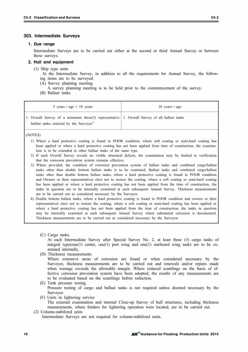
A survey planning meeting is to be held prior to the commencement of the survey.(B) Ballast tanks
5 years < age ≤ 10 years 10 years < age
1. Overall Survey of a minimum three(3) representative
ballast tanks selected by the Surveyor1)
1. Overall Survey of all ballast tanks
(NOTES)
1) Where a hard protective coating is found in POOR condition, where soft coating or semi-hard coating has been applied or where a hard protective coating has not been applied from time of construction, the examina-tion is to be extended to other ballast tanks of the same type.
2) If such Overall Survey reveals no visible structural defects, the examination may be limited to verification that the corrosion prevention system remains effective.
3) Where provided, the condition of corrosion prevention system of ballast tanks and combined cargo/ballast tanks other than double bottom ballast tanks is to be examined. Ballast tanks and combined cargo/ballast tanks other than double bottom ballast tanks, where a hard protective coating is found in POOR condition and Owners or their representatives elect not to restore the coating, where a soft coating or semi-hard coating has been applied or where a hard protective coating has not been applied from the time of construction, the tanks in question are to be internally examined at each subsequent Annual Survey. Thickness measurements are to be carried out as considered necessary by the Surveyor.
4) Double bottom ballast tanks, where a hard protective coating is found in POOR condition and owners or their representatives elect not to restore the coating, where a soft coating or semi-hard coating has been applied or where a hard protective coating has not been applied from the time of construction, the tanks in question may be internally examined at each subsequent Annual Survey where substantial corrosion is documented. Thickness measurements are to be carried out as considered necessary by the Surveyor.
(C) Cargo tanksAt each Intermediate Survey after Special Survey No. 2, at least three (3) cargo tanks of integral type(one(1) center, one(1) port wing and one(1) starboard wing tank) are to be ex-amined internally.
(D) Thickness measurementsWhere extensive areas of corrosion are found or when considered necessary by the Surveyor, thickness measurements are to be carried out and renewals and/or repairs made when wastage exceeds the allowable margin. Where reduced scantlings on the basis of ef-fective corrosion prevention system have been adopted, the results of any measurements are to be evaluated based on the scantlings before reduction.
(E) Tank pressure testingPressure testing of cargo and ballast tanks is not required unless deemed necessary by the Surveyor.
(F) Units in lightering serviceThe external examination and internal Close-up Survey of hull structures, including thickness measurements, where fenders for lightering operation were located, are to be carried out.
(2) Column-stabilized units Intermediate Surveys are not required for column-stabilized units.
Ch 2 Classification and Surveys Ch 2
Guidance for Floating Production Units 2015 17
3. Fire protection and fire fighting systems
At each Intermediate Survey, all the requirements of Annual Survey are to be complied with.
4. Machinery and electrical equipment
At each Intermediate Survey, all the requirements of Annual Survey are to be complied with.
5. Dynamic positioning systems (if relevant notations are assigned)
At each Intermediate Survey, all the requirements of Annual Survey are to be complied with.
6. Production systems (if relevant notations are assigned)
At each Intermediate Survey, all the requirements of Annual Survey are to be complied with.
7. Import and export systems (if relevant notations are assigned)
At each Intermediate Survey, all the requirements of Annual Survey are to be complied with.
304. Special Surveys
1. Due range
(1) A Special Survey is to be completed within five(5) years after the date of build or after the crediting date of the previous Special Survey. The fifth Annual Survey must be credited as a requirement of the Special Survey. The interval between Special Survey may be reduced by the Society if it considered necessary.
(2) Special Survey may be commenced at the fourth Annual Survey and be continued with com-pletion by the fifth anniversary date. Where the Special Survey is commenced prematurely, the entire survey is normally to be completed within 15 months if such work is to be credited to the Special Survey.
(3) Special consideration may be given to Special Survey requirements in the case of units of un-usual design, in lay-up or in unusual circumstances. Consideration may be given for extensions of rule-required Special Surveys under exceptional circumstances.
2. Hull and equipment
Special Survey is to include compliance with the Annual Survey and Docking Survey requirements and, in addition, the following requirements as listed below are to be performed, as applicable, the parts examined, placed in satisfactory condition and reported upon.(1) Ship type units In addition to the requirements of the Annual Survey, the Special Survey is to include suffi-
cient examination, tests and checks carried out by the Surveyors to satisfy themselves that the hull, equipment and related piping are in or are placed in satisfactory condition and are fit for the intended purpose for the new period of class of five(5) years to be assigned, subject to proper maintenance and operation and to periodical surveys being carried out at the due dates. Special Survey is to include the following:(A) Survey planning meeting
A survey planning meeting is to be held prior to the commencement of the survey.(B) Docking Survey
Docking surveys are to be carried out in accordance with 305.(C) Rudder
When the steering gear is maintained operational the rudder is to be examined and, when considered necessary by the Surveyor, lifted and the gudgeons rebushed. The condition of rudder carrier and steadiment/rudder stock bearings and the effectiveness of stuffing boxes are to be ascertained when the rudder is lifted.
(D) Mooring systemsSince it is impractical to cover all types of mooring systems, the following are provided as guidance to show the basic intent of the survey requirements. Operators and designers may submit alternative survey requirements based either on service experience or manufacturer' recommendations. If considered acceptable by the Society, these alternative survey proce-dures will form the basis for the Special Survey of the mooring system. The Special Survey is to include all items listed under the Annual Survey and, in addition, the following are to be performed, where applicable:
Ch 2 Classification and Surveys Ch 2
18 Guidance for Floating Production Units 2015
(a) A Docking Survey or equivalent In-water Survey of the SPM system is to be carried out. This survey is to include examination of the entire structure of the SPM, the pro-tective coating, cathodic protection system, the chain stoppers and their locking devices. Any suspect areas where substantial corrosion is evident are to be thickness gauged. Gaugings to the extent considered necessary by the Surveyor are to be taken on the structures of the SPM when it has undergone service for 15 years or more.
(b) An examination is to be made on all anchor chains for substantial corrosion and wastage. In particular, the areas to be specially examined are the areas having the most relative movement between the chain links. These areas are normally located in way of the seabed touchdown sections of the catenary part of the chains. The chains are to be inspected for looses studs and link elongations. Sufficient representative locations are to be gauged for wear and wastage. Areas susceptible to corrosion, such as the wind-and-water areas, are to be specially gauged, if considered necessary by the attend-ing Surveyor.
(c) A close examination is to be carried out on all mooring components and accessible structural members that carry the mooring loads. These structures include the chain stop-pers or cable holders, the structures in way of the chain stoppers or cable holders, structural bearing housing and turret/structural well annulus areas. These structures are to be thoroughly cleaned and examined and any suspect areas are to be nondestructively tested.
(d) A general inspection is also to be carried out on the degree of scour or exposure in way of the anchor or anchor piles to ascertain that these components are not overexposed.
(e) An examination is to be carried out on the main bearing of the SPM system. This ex-amination is to include visual inspection of bearing, if accessible, for water ingress into the structural housing, corrosion, pitting and substantial wear. If the bearing is in-accessible, at least the weardown is to be ascertained and the condition of the bearing seals verified. If disassembled, the bearing rollers and the racer housings are to be examined.
(f) For inaccessible structures, special alternative inspection procedures for inspection of these areas are to be submitted for approval.
(g) The chain tensions are to be checked and where found not in compliance with the spec-ifications are to be readjusted accordingly. Excessive loss of chain or tendon tensions are to be investigated.
(h) Representative areas of the chains are to be examined and checked for substantial wastage. In particular, areas in way of the chain stoppers and the seabed touchdown areas are to be specially examined and measured for substantial wear.
(i) For disconnectable type mooring systems, the disconnect and connect system for the mooring system is to be tested as considered necessary by the Surveyor. Alternatively, records of disconnect/connect operations between the credit date of the last Special Survey and the current due date of same may be reviewed, and if found satisfactory, it may be considered to have been in compliance with this requirement.
(E) Shell openings and their closuresAll openings in the shell including overboard discharges are to be examined.
(F) Decks, bulkheads and shell platingAll decks, watertight bulkheads, and internal and external surfaces of shell plating are to be examined. Plating in way of side shell or superstructure portlights is to be especially examined.
(G) Overall Survey requirement(a) Spaces
(i) An Overall Survey of all spaces including cargo holds and their tween decks, where fitted; double bottom, deep, ballast, peak and cargo tanks; pumprooms, pipe tunnels, duct keels, machinery spaces, dry spaces, cofferdams and voids, including the plating and framing, bilges and drain wells, sounding, venting, pumping and drainage arrangements.
(ii) Internal examination of fuel oil, lube oil and fresh water tanks is to be carried out in accordance with (d) below.
(iii) Where sounding pipes are fitted, the Surveyor is to confirm that a striking pad is securely fixed below the sounding pipe.
Ch 2 Classification and Surveys Ch 2
Guidance for Floating Production Units 2015 19
(iv) Electrical bonding arrangements, including bonding straps where fitted, for the pip-ing systems located within cargo tanks, pipe tunnels, cofferdams and void spaces bounding cargo tanks are also to be examined.
(v) This examination is to be supplemented by thickness measurement and testing as re-quired in this Guidance to ensure that the structural integrity remains effective. The aim of the examination is to discover substantial corrosion, significant deformation, fractures, damages or other structural deterioration, that may be present.
(b) Engine room spacesEngine room structure is to be examined. Particular attention is to be given to tank tops, shell plating in way of tank tops, brackets connecting side shell frames and tank tops, and engine room bulkheads in way of tank top and bilge wells. Particular atten-tion is to be given to the sea suction, seawater cooling pipes and overboard discharge valves and their connections to the side shell plating. Where wastage is evident or sus-pect, thickness measurements are to be carried out, and renewals and/or repairs made where wastage exceeds allowable limits.
(c) Ballast tanks and combined cargo/ballast tanks(i) Where provided, the condition of corrosion prevention system of ballast tanks and
combined cargo/ballast tanks is to be examined.(ii) Ballast tanks and combined cargo/ballast tanks other than double bottom ballast
tanks, where a hard protective coating is found in POOR condition and Owners or their representatives elect not to restore the coating, where soft coating or semi-hard coating has been applied or where a hard protective coating has not been applied from the time of construction, the tanks in question are to be internally examined at each subsequent Annual Survey. Thickness measurements are to be carried out as deemed necessary by the Surveyor.
(iii) When such breakdown of hard protective coating is found in double bottom ballast tanks and owners or their representatives elect not to restore the coating, where a soft coating or semi-hard coating has been applied, or where a hard protective coat-ing has not been applied from the time of construction, the tanks in question are to be internally examined at each subsequent Annual Survey where substantial corrosion is documented. Thickness measurements are to be carried out as considered neces-sary by the Surveyor.
(d) Fuel oil, lubrication oil, fresh water and permanent ballast tanks(i) Internal examination requirements will be specially considered for tanks used ex-
clusively for permanent ballast which are fitted with an effective means of corrosion control.
(ii) Where tanks of integral structural type, except for peak tanks, are used primarily for heavy fuel oil or exclusively for light oils or fresh water, the internal examina-tion may be specially considered, provided a general external examination and the following internal examinations are carried out if considered necessary by the Surveyor.
(iii) Independent oil tanks in machinery spaces are to be externally examined and, if considered necessary by the Surveyor, tested under a head of liquid to the highest point that liquid will rise under service conditions.
(iv) Minimum requirements for internal examination of fuel oil, lubrication oil and fresh water tanks at Special Surveys are as follows.
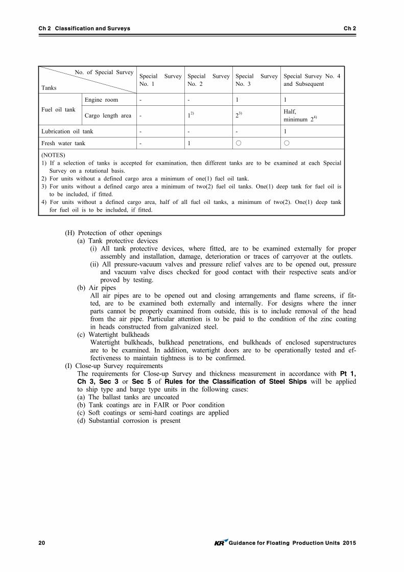
Ch 2 Classification and Surveys Ch 2
20 Guidance for Floating Production Units 2015
No. of Special Survey
Tanks
Special Survey No. 1
Special Survey No. 2
Special Survey No. 3
Special Survey No. 4 and Subsequent
Fuel oil tank
Engine room - - 1 1
Cargo length area - 12) 23) Half,minimum 24)
Lubrication oil tank - - - 1
Fresh water tank - 1 ○ ○
(NOTES)1) If a selection of tanks is accepted for examination, then different tanks are to be examined at each Special
Survey on a rotational basis.2) For units without a defined cargo area a minimum of one(1) fuel oil tank.3) For units without a defined cargo area a minimum of two(2) fuel oil tanks. One(1) deep tank for fuel oil is
to be included, if fitted.4) For units without a defined cargo area, half of all fuel oil tanks, a minimum of two(2). One(1) deep tank
for fuel oil is to be included, if fitted.
(H) Protection of other openings(a) Tank protective devices
(i) All tank protective devices, where fitted, are to be examined externally for proper assembly and installation, damage, deterioration or traces of carryover at the outlets.
(ii) All pressure-vacuum valves and pressure relief valves are to be opened out, pressure and vacuum valve discs checked for good contact with their respective seats and/or proved by testing.
(b) Air pipesAll air pipes are to be opened out and closing arrangements and flame screens, if fit-ted, are to be examined both externally and internally. For designs where the inner parts cannot be properly examined from outside, this is to include removal of the head from the air pipe. Particular attention is to be paid to the condition of the zinc coating in heads constructed from galvanized steel.
(c) Watertight bulkheadsWatertight bulkheads, bulkhead penetrations, end bulkheads of enclosed superstructures are to be examined. In addition, watertight doors are to be operationally tested and ef-fectiveness to maintain tightness is to be confirmed.
(I) Close-up Survey requirementsThe requirements for Close-up Survey and thickness measurement in accordance with Pt 1, Ch 3, Sec 3 or Sec 5 of Rules for the Classification of Steel Ships will be applied to ship type and barge type units in the following cases:(a) The ballast tanks are uncoated(b) Tank coatings are in FAIR or Poor condition(c) Soft coatings or semi-hard coatings are applied(d) Substantial corrosion is present
Ch 2 Classification and Surveys Ch 2
Guidance for Floating Production Units 2015 21
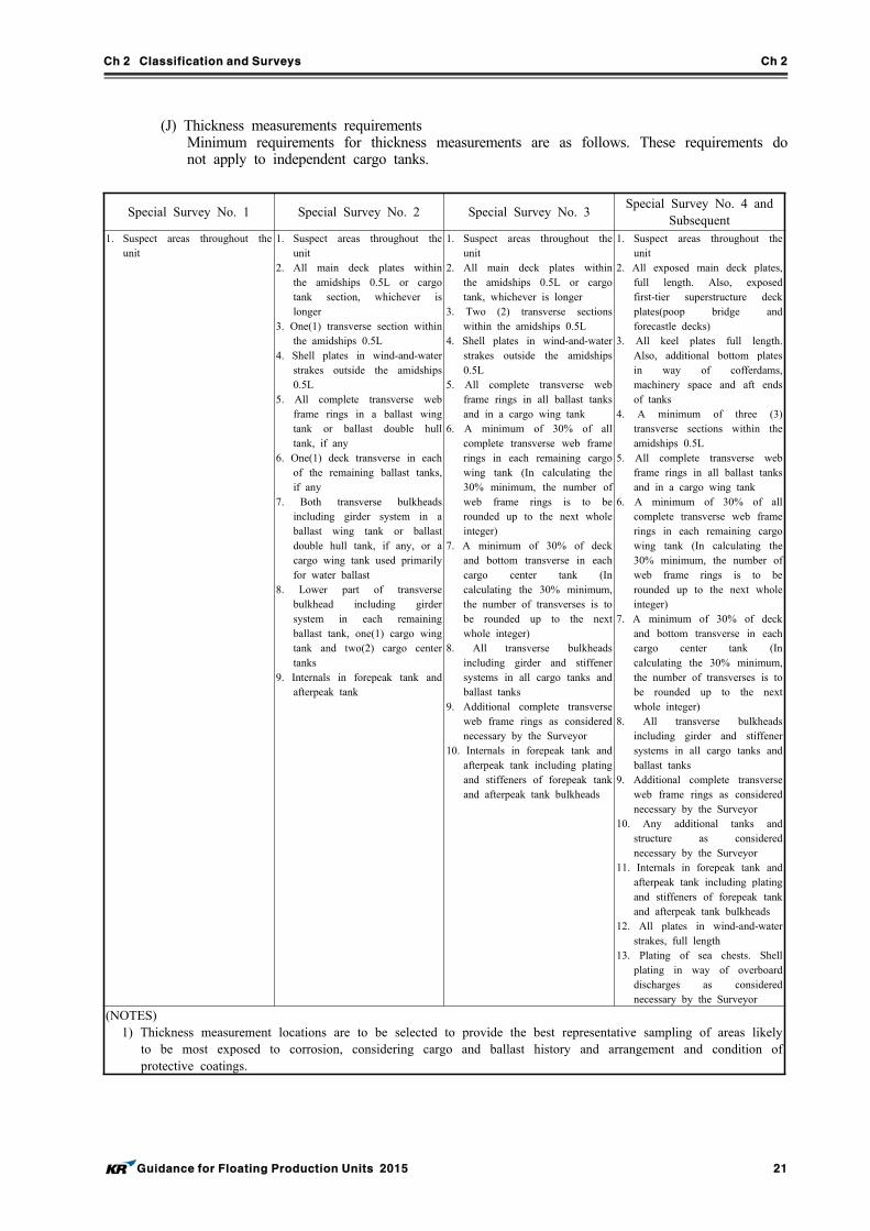
(J) Thickness measurements requirementsMinimum requirements for thickness measurements are as follows. These requirements do not apply to independent cargo tanks.
Special Survey No. 1 Special Survey No. 2 Special Survey No. 3Special Survey No. 4 and
Subsequent1. Suspect areas throughout the
unit1. Suspect areas throughout the
unit2. All main deck plates within
the amidships 0.5L or cargo tank section, whichever is longer
3. One(1) transverse section within the amidships 0.5L
4. Shell plates in wind-and-water strakes outside the amidships 0.5L
5. All complete transverse web frame rings in a ballast wing tank or ballast double hull tank, if any
6. One(1) deck transverse in each of the remaining ballast tanks, if any
7. Both transverse bulkheads including girder system in a ballast wing tank or ballast double hull tank, if any, or a cargo wing tank used primarily for water ballast
8. Lower part of transverse bulkhead including girder system in each remaining ballast tank, one(1) cargo wing tank and two(2) cargo center tanks
9. Internals in forepeak tank and afterpeak tank
1. Suspect areas throughout the unit
2. All main deck plates within the amidships 0.5L or cargo tank, whichever is longer
3. Two (2) transverse sections within the amidships 0.5L
4. Shell plates in wind-and-water strakes outside the amidships 0.5L
5. All complete transverse web frame rings in all ballast tanks and in a cargo wing tank
6. A minimum of 30% of all complete transverse web frame rings in each remaining cargo wing tank (In calculating the 30% minimum, the number of web frame rings is to be rounded up to the next whole integer)
7. A minimum of 30% of deck and bottom transverse in each cargo center tank (In calculating the 30% minimum, the number of transverses is to be rounded up to the next whole integer)
8. All transverse bulkheads including girder and stiffener systems in all cargo tanks and ballast tanks
9. Additional complete transverse web frame rings as considered necessary by the Surveyor
10. Internals in forepeak tank and afterpeak tank including plating and stiffeners of forepeak tank and afterpeak tank bulkheads
1. Suspect areas throughout the unit
2. All exposed main deck plates, full length. Also, exposed first-tier superstructure deck plates(poop bridge and forecastle decks)
3. All keel plates full length. Also, additional bottom plates in way of cofferdams, machinery space and aft ends of tanks
4. A minimum of three (3) transverse sections within the amidships 0.5L
5. All complete transverse web frame rings in all ballast tanks and in a cargo wing tank
6. A minimum of 30% of all complete transverse web frame rings in each remaining cargo wing tank (In calculating the 30% minimum, the number of web frame rings is to be rounded up to the next whole integer)
7. A minimum of 30% of deck and bottom transverse in each cargo center tank (In calculating the 30% minimum, the number of transverses is to be rounded up to the next whole integer)
8. All transverse bulkheads including girder and stiffener systems in all cargo tanks and ballast tanks
9. Additional complete transverse web frame rings as considered necessary by the Surveyor
10. Any additional tanks and structure as considered necessary by the Surveyor
11. Internals in forepeak tank and afterpeak tank including plating and stiffeners of forepeak tank and afterpeak tank bulkheads
12. All plates in wind-and-water strakes, full length
13. Plating of sea chests. Shell plating in way of overboard discharges as considered necessary by the Surveyor
(NOTES)1) Thickness measurement locations are to be selected to provide the best representative sampling of areas likely
to be most exposed to corrosion, considering cargo and ballast history and arrangement and condition of protective coatings.
Ch 2 Classification and Surveys Ch 2
22 Guidance for Floating Production Units 2015
(K) Tank testing(a) Boundaries of double bottom, deep, ballast, peak and other tanks, including holds adapt-
ed for the carriage of water ballast if fitted, are to be tested with a head of liquid to the top of air pipes or to near the top of hatches for ballast/cargo holds, except that cargo tanks on ship type units of both single and double hull construction may be test-ed to the highest point that liquid will rise under service condition. Boundaries of fuel oil, lube oil and fresh water tanks may be tested with a head of liquid to the highest point that liquid will rise under service condition. Tank testing of fuel oil, lube oil and fresh water tanks may be specially considered based on a satisfactory external examina-tion of the tank boundaries, and a confirmation from the Master stating that the pressure testing has been carried out according to the requirements with satisfactory results, pro-vided that representative tanks for fuel oil, lube oil and fresh water are tested.
(b) The testing of double bottoms and other spaces not designed for the carriage of liquid may be omitted, provided a satisfactory internal examination together with an examina-tion of the tanktop is carried out.
(c) Stagger testing of bulkheads is acceptable as alternative means of testing.(d) The Surveyor may require further tank testing, as deemed necessary.
(L) Units in lightering serviceThe external examination and internal Close-up Survey of hull structures, including thickness measurements, where fenders for lightering operation were located are to be carried out.
(2) Column-stabilized units For column-stabilized units, the following are to be performed, as applicable, the parts exam-
ined, placed in satisfactory condition and reported upon:(A) The hull or platform structure, including tanks, watertight bulkheads and decks, cofferdams,
void spaces, sponsons, chain locker, deck, keels, helicopter pad, machinery spaces, peak spaces, steering gear spaces and all other internal spaces are to be examined externally and internally for damage, fractures or excessive wastage.
(B) All tanks, compartments and free-flooding spaces throughout the unit are to be examined ex-ternally and internally. Internal examinations of lower hull are to be specially considered. Watertight integrity of tanks, bulkheads, hull, bulkhead deck and other compartments are to be verified by visual inspection. Suspect areas may be required to be tested for tightness, nondestructively tested or thickness gauged. Tanks and other normally closed compartments are to be ventilated, gas-freed and cleaned, as necessary, to expose damage and allow for a meaningful examination for substantial wastage. Internal examination and testing of void spaces, compartments filled with foam or corrosion inhibitors and tanks used only for lube oil, light fuel oil, diesel oil or other non-corrosive products may be waived, provided that, upon general examination, the Surveyor considers their condition to be satisfactory. External thickness gauging may be required to confirm corrosion control.
(C) Attachments of anchor racks and anchor cable fairleads are to be examined. Foundations in way of selective anchor line fairlead support structures are to be cleaned and nondestructive examinations performed. Internal support structures in way of these foundations are to be closely examined.
(D) Applicable structures, such as pipe racks, process support structures, deck houses, super-structures, helicopter landing areas and their respective attachments to the deck or hull.
(E) Foundations and supporting headers, brackets and stiffeners for process related apparatus, where attached to hull, deck, superstructure or deck house.
(F) Survey of parts of the unit that are underwater and inaccessible to the Surveyor may be ac-cepted on the basis of an examination by a qualified diver, conducted in the presence of the Surveyor. Video or photo records, nondestructive testing and thickness gauging may be required in addition to the diver's report.
(G) At each Special Survey, thickness gaugings are to be performed where wastage is evident or suspected. Special attention should be paid to the splash zones on hulls, columns and ballast tanks, free-flooded spaces and the bottom hulls.
(H) Where inspection of underwater parts is required, the in-water visibility and the cleanliness are to be clear enough to permit a meaningful examination which allows the Surveyor and diver to determine the condition of underwater parts.
(I) Connections of columns and diagonals to upper hull or platform and lower hull or pontoons. Joints of supporting structure, including diagonals, braces and horizontals, together with gus-sets and brackets. Internal continuation or back-up structure for the above. Nondestructive
Ch 2 Classification and Surveys Ch 2
Guidance for Floating Production Units 2015 23
examination may be required at suspect areas.
3. Fire protection and fire fighting systems
Special Survey is to include compliance with the Annual Survey requirements and, in addition, the following requirements as listed below are to be performed, as applicable, the parts examined, placed in satisfactory condition and reported upon. Following systems are to be verified to confirm no significant changes have been made to any of the systems and that they remain in satisfactory condition. (1) Fire protection systems, including the following items are to be tested:
(A) Function testing of all fire doors (B) Function testing of all ventilation fire-dampers (C) Function testing of all ventilation system closures and stoppage of power ventilation (D) Function testing of all shutters or water curtains
(2) Fixed fire extinguishing systems, including the following items are to be tested: (A) Function testing of all fire pumps. This is to include confirmatory testing of the fire pump
capacity and testing of relief valves of the fixed fire main system. (B) Hydrostatic testing of the fire main system (C) Hydrostatic testing of fire hoses, as necessary
(3) Fire detection and alarm systems are to be tested. (4) Gas detection and alarm systems are to be tested. (5) Means of escape, including the following items are to be tested:
(A) Lighting and grating in way of all escape routes (B) Contact makers for general alarm system, communication system installed in all emergency
control stations (6) Emergency shutdown systems
(A) Emergency shutdown arrangements provided to disconnect or shutdown, either selectively or simultaneously, of the electrical equipment as outlined in the unit’s operating manual, are to be tested.
(B) Services such as the emergency lighting, general alarm system, public address system, dis-tress and safety radio system, that are required to be operable after an emergency shutdown of the installation, are to be verified for their proper operation.
4. Machinery and electrical equipment
Special Survey is to include compliance with the Annual Survey requirements and, in addition, the following requirements as listed below are to be performed, as applicable, the parts examined, placed in satisfactory condition and reported upon. (1) Correlation with Special Survey of hull
(A) Main and auxiliary engines of all types of installations are to undergo Special Periodical Survey at intervals similar to those for Special Survey of hull in order that both may be re-corded at approximately the same time.
(B) In cases where damage has involved extensive repairs and examination, the survey thereon may be considered as equivalent to a Special Survey.
(2) Machinery Parts to be Examined (A) All openings to the sea, including sanitary and other overboard discharges together with the
cocks and valves connected therewith, are to be examined internally and externally while the installation is in drydock or at the time of underwater examination in lieu of drydocking, and the fastenings to the shell plating are to be renewed when considered necessary by the Surveyor.
(B) Pumps and pumping arrangements, including valves, cocks, pipes, and strainers, are to be examined.
(C) Nonmetallic flexible expansion pieces in the main salt-water circulating system are to be ex-amined internally and externally.
(D) The Surveyor is to be satisfied with the operation of the bilge and ballast systems. Other systems are to be tested as considered necessary.
(E) The foundations of machinery are to be examined. (F) Heat exchangers and other unfired pressure vessels with design pressures over 0.7 MPa are
to be examined, opened out or thickness gauged and pressure tested as considered necessary, and associated relief valves proven operable.
(3) Electrical Parts to be Examined (A) Fittings and connections on main switchboards and distribution panels are to be examined.
Ch 2 Classification and Surveys Ch 2
24 Guidance for Floating Production Units 2015
(B) Cables are to be examined as far as practicable without undue disturbance of fixtures. (C) All generators are to be run under load, either separately or in parallel; switches and circuit
breakers are to be tested. (D) All equipment and circuits are to be inspected for possible development of physical changes
or deterioration. The insulation resistance of the circuits is to be measured between con-ductors and between conductors and ground and these values compared with those pre-viously measured. Any large and abrupt decrease in insulation resistance is to be further in-vestigated and either restored to normal or renewed as indicated by the conditions found.
(F) The specified electrical auxiliaries for vital purposes, generators and motors are to be exam-ined and their prime movers opened for inspection. The insulation resistance of each gen-erator and motor is to be measured.
(G) The accumulator batteries are to be examined, including their maintenance schedule and the society reviewed procedure of maintenance.
(H) Bilge alarm system, if fitted, is to be tested and proven satisfactory. (I) Non-explosion proof electric motors are to be examined, including automatic power dis-
connect to motors that are arranged to shut down in case of loss of ventilation. (4) Surveys of machinery that has been accepted for surveys based on preventative maintenance
techniques are to comply with the requirements of Pt 1, Annex 1-8 of Guidance relating to the Rules for the Classification of Steel Ships.
(5) On self-propelled installations, in addition to the requirements for Annual Survey and the appli-cable requirements of above (2), the main and auxiliary machinery are to be surveyed in ac-cordance with the requirements of Pt of Guidance relating to the Rules for the Classification of Steel Ships as applicable to self-propelled vessels.
5. Inert Gas Systems
Surveys of dynamic positioning systems are to comply with the requirements of Pt 1, Ch 2, Sec 5-1, Par 1 of Rules for the Classification of Steel Ships.
6. Dynamic positioning systems (if relevant notations are assigned)
Surveys of dynamic positioning systems are to comply with the requirements of Pt 9, Ch 4 of Rules for the Classification of Steel Ships.
7. Production systems (if relevant notations are assigned)
(1) Maintenance records are to be kept and made available for review by the Surveyor. The main-tenance records will be reviewed to establish the scope and content of the required Annual and Special Periodical Surveys. During the service life of the facilities, maintenance records are to be updated on a continuing basis. The operator is to inform the Society of any changes to the maintenance procedures and frequencies, as may be caused, for example, by changes or addi-tions to the original equipment.
(2) Internal examination of pressure vessels, pumps, compressors, and safety relief valves(3) Random thickness gauging of process piping, as considered necessary(4) Hydrostatic testing of process related piping systems to 1.25 times the maximum allowable
working pressure as considered necessary. (5) Lube oil examination record review (6) Measurement of the insulation resistance of generators and motors ix) Running of generators of
under load, separately and in parallel(7) Examination of cable runs, bus ducts, insulators, etc. (8) Testing of circuit breakers, relays, etc. (9) Examination of electrical equipment and circuits for possible damage or deterioration (10) Vibration checks of rotating machinery (11) Internal examination of steam and gas turbines, as considered necessary (12) Testing of protective devices for engines, turbines, and gas compressors (13) Internal examination of diesel engines and gas engines rated 1000 hp output and above, as
considered necessary (14) Operational check of process control equipment.
8. Import and export systems (if relevant notations are assigned)
Special Survey is to include all items listed under the Annual Survey and, in addition, the follow-ing are to be performed. However, survey items may modified according to types of import and export systems. Operators and designers may submit alternative survey requirements based either on
Ch 2 Classification and Surveys Ch 2
Guidance for Floating Production Units 2015 25
service experience or manufacturer’s recommendations. Upon review, these alternative survey proce-dures may accepted by the Society. (1) Fluid and electrical swivels are to be disassembled, if considered necessary, and examined for
wear and tear. The seals are to be examined. Upon completion of the reconditioning, the fluid swivels are to be hydrostatically tested. Similarly, the electrical swivels are to be insulation test-ed upon reassembly.
(2) During underwater inspection of the SPM system, flexible risers are to be examined, including all arch support buoyancy tanks. Risers are to be inspected for damage in high stress areas, such as areas in way of the end flanges, areas in way of the arch support clamps and the bot-tom of all looped areas. Spreader bars, if fitted to separate one riser string from another, are to be inspected for wear and tear. Hydrostatic tests may be required to be conducted on the risers, as deemed necessary by the Surveyor.
(3) For deep sea applications, riser suspension or support systems are to be examined for deterio-ration and loss of tension. Support areas in way of the riser are to be closely examined for fretting corrosion, wear, kinks, creases, etc.
(4) Floating export hoses are to be examined for kinks, surface cracks, chafing damages, etc. Hydrostatic and vacuum tests may be required to be conducted on the floating hose string, as deemed necessary by the Surveyor.
(5) All piping systems are to be opened up for examination. Nondestructive and hydrostatic tests may be required, where considered necessary by the attending Surveyor.
(6) For disconnectable type mooring systems, the disconnect and connect arrangements for the im-port and export systems are to be tested, as considered necessary by the Surveyor. Alternatively, records of disconnect/connect operations between the credit date of the last SPS and the current due date of same may be reviewed, and if found satisfactory, it may be considered to have complied with this requirement.
(7) Hoses designed and manufactured based on OCIMF standards are to be tested in accordance with the "OCIMF Guide for the Handling, Storage, Inspection, and Testing of Hoses in the Field".
305. Docking Survey
The underwater parts of a unit are to be examined at certain intervals. This examination may be conducted by In-water Survey in lieu of drydocking or, if necessary, a survey on drydock. During this survey, the Surveyors are to survey the unit, its structural condition, corrosion protection sys-tem, mooring system and(if classed) the import and export systems.
1. Due range
(1) There is to be a minimum of two Docking Survey during each five-year Special Survey period. One such Docking Survey is to be carried out in conjunction with the Special Survey. In all cases the interval between any two such Docking Surveys is not to exceed 36 months.
(2) Consideration may be given for extensions of rule-required Docking Survey under exceptional circumstances. An In-water Survey may be required for such extensions.
2. Requirements of survey
(1) For ship type and barge type units, the following items are to be examined, as applicable:The keel, stem, stern frame, rudder, propeller, and outside of side and bottom plating are to be cleaned as necessary and examined, together with bilge keels, thrusters, exposed parts of the stern bearing and seal assembly, sea chest, rudder pintles and gudgeons, together with their re-spective securing arrangements. All sea connections and overboard discharge valves and cocks, including their attachments to the hull or sea chests, are to be externally examined. All non-metallic expansion pieces in the sea-water cooling and circulating systems are to be examined both externally and internally. The stern bearing clearance or weardown and rudder bearing clearances are to be ascertained and reported on.
(2) For column-stabilized units, the following are to be examined:(A) External surfaces of the upper hull or platform, footings, pontoons or lower hulls, under-
water areas of columns, bracing and their connections, as applicable, are to be selectively cleaned and examined. These areas include joints of critical structural members, areas sus-ceptible to damage from offshore support vessels, anchor chains, dropped equipment, corro-sion and erosion from loss of coating, or sand scouring and areas of progressed and accu-mulated wear-and-tear.
Ch 2 Classification and Surveys Ch 2
26 Guidance for Floating Production Units 2015
(B) Nondestructive testing may be required of areas found to be suspect. Joints of different con-figurations of major structural members are to be selected, cleaned and magnetic particle inspected. The selection of these joints are to be such that all joints underwater are to be inspected every five years.
(C) Sea chests and strainers are to be cleaned and examined.(D) External portions of propulsion units are to be examined, if applicable.(E) The type, location and extent of corrosion control(coatings, cathodic protection systems, etc.),
as well as effectiveness, and repairs or renewals to same should be reported in each survey. Particular attention is to be given to corrosion control systems in ballast tanks, free-flooding areas and other locations subjected to sea water from both sides.
(F) All tanks and voids that are to be internally examined are to be thoroughly ventilated and gas freed prior to being entered and are to be carefully monitored for pocketing or emis-sions of hazardous gases during examination.
(G) In conjunction with Docking Surveys(or equivalent In-water Surveys), the following ballast tanks are to be internally examined, and the effectiveness of coatings or corrosion control arrangements are to be verified either visual inspection or by thickness gauging(as consid-ered necessary), placed in satisfactory condition, as found necessary, and reported upon:(a) Representative ballast tanks in footings, lower hulls or free-flooding compartments, as ac-
cessible(b) At least two ballast tanks in columns or upper hull, if applicable
(3) Corrosion prevention system - underwater bodyIn addition to the above (1) and (2) requirements, the following are to be to be performed dur-ing all of the Docking Surveys(or equivalent In-water Surveys):(A) Cathodic potential readings are to be taken from representative positions on the entire under-
water body and evaluated to confirm that the cathodic protection system is operating within design limits.
(B) Sacrificial anodes are to be examined for depletion and placed in satisfactory condition, as considered necessary.
(C) Impressed current system anodes and cathodes are to be checked for damage, fouling by marine growth and carbonate deposits. The current and voltage demands of the system are to also be checked to ensure the system is functioning properly.
(D) Additional examinations are to be performed on the wind and water areas of the structures where coating breaks are evident. Thickness measurements in these areas may be required if found necessary by the attending Surveyor.
(4) Mooring systemFor mooring systems, the following are to be cleaned and examined, where applicable:(A) The mooring anchor chain or cable tensions are to be measured and the end connections of
these components are to be examined. All mooring chains are to be generally examined for their entire lengths.
(B) Anchors, cables and their respective handling means are to be examined.(C) The buoyancy tanks are to be cleaned and examined, if applicable.(D) Chain and stopper assemblies are to be cleaned, examined and NDE performed, as consid-
ered necessary by the Surveyor.(E) Areas of high stress or low fatigue life are to be preselected, cleaned and NDE performed,
if considered necessary.(F) Scour in way of anchors or anchor piles is to be examined.(G) Cathodic potential readings are to be taken from representative positions on the entire un-
derwater structure of the mooring system to confirm that the cathodic protection system is operating within design limits.
(H) Highly stressed, high wear and tear areas of the mooring chain are to be closely examined and nondestructively tested, if considered necessary by the Surveyor. These include areas in way of the stoppers and sea bed touchdown areas.
(5) Import and export systems (if relevant notations are assigned)(A) For import systems, the following are to be cleaned and examined, where applicable:
(a) The entire riser system. (b) The arch support buoyancy tanks, their structures and the clamping devices.(c) The flexible riser, including all end flanges and bolting arrangements and spreader bars. (d) Hoses designed and manufactured based on OCIMF standards are to be tested in accord-
ance with the "OCIMF Guide for the Handling, Storage, Inspection, and Testing of
Ch 2 Classification and Surveys Ch 2
Guidance for Floating Production Units 2015 27
Hoses in the Field". (B) For export systems, the following are to be cleaned and examined, where applicable:
(a) The entire export flexible system is to be examined for damage due to chafing and fa-tigue fractures.
(b) Hoses designed and manufactured based on OCIMF standards are to be tested in accord-ance with the "OCIMF Guide for the Handling, Storage, Inspection, and Testing of Hoses in the Field".
(c) All navigation aids are to be examined and functionally tested.
3. In-water Survey
(1) For units with IWS notation in accordance with relevant requirements specified in Pt 1, Ch 2, 604. of Rule for the Classification of Steel Ships, an approved In-water Survey by a diver may be considered equivalent to a Docking Survey, up to and including Special Survey No. 4. The In-water Survey Procedures in accordance with Ch 2, Sec 3, 309. of Rules for the Classification of Mobile Offshore Drilling Units are to be submitted for review and approval in advance of the survey.
This approved procedure is to be made available onboard. In addition, the inspection procedures are to also consist of the following:(A) Scope of inspection(B) Procedure for divers to identify the exact location at which they are conducting their in-
spection(C) Procedure for cleaning the marine growth for inspection purposes that is to include the ex-
tent and location of the underwater cleaning(D) Procedure and extent for measuring the cathodic potential readings in way of the structures(E) Procedure and extent for taking thickness measurements of the structures and NDE of crit-
ical joints(F) Qualifications of all divers conducting the inspection, NDE and thickness measurements(G) The type of underwater video and photography, including means of communication, monitor-
ing and recording(H) For In-water Surveys in lieu of Docking Surveys associated with Special Survey, means are
to be provided to permit the opening up of all sea valves and overboard discharges for in-ternal examination. In addition, all Special Survey items related to the underwater portion of the hull or structure, including the thickness measurement requirements are to be dealt with during the In-water Survey.
(2) For each In-water Survey in lieu of Docking Survey after Special Survey No. 4, requests to conduct an In-water Survey are to be submitted for consideration well in advance of the pro-posed survey. Approvals to conduct the In-water Survey in lieu of Docking Survey after Special Survey No. 4 are to be made available onboard for the Surveyor's reference.
306. Tail Shaft and Tube Shaft Surveys
For Tail Shaft Surveys of self-propelled units, applicable requirements of Pt 1, Ch 2, Sec 7 of Rule for the Classification of Steel Ships are to be complied with. However, due to low run-ning hours on tail shafts of units, the interval between tail shaft surveys may be extended based on the following being performed to the satisfaction of the Surveyor: (1) Diver’s external examination of stern bearing and outboard seal area, including weardown check
as far as is possible. (2) Examination of the shaft area (inboard seals) in propulsion rooms. (3) Confirmation of lubricating oil records (satisfactory oil loss rate, no evidence of unacceptable
contamination). (4) Shaft seal elements are to be examined/replaced in accordance with seal manufacturer’s
recommendations.
307. Boiler Surveys
Boiler Surveys are to comply with the requirements of Pt 1, Ch 2, Sec 8 of Rule for the Classification of Steel Ships.
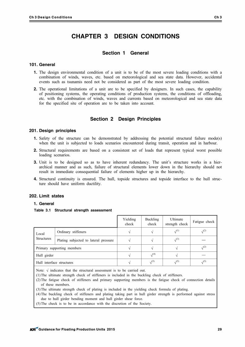
Ch 3 Design Conditions Ch 3
Guidance for Floating Production Units 2015 29
CHAPTER 3 DESIGN CONDITIONS
Section 1 General
101. General
1. The design environmental condition of a unit is to be of the most severe loading conditions with a combination of winds, waves, etc. based on meteorological and sea state data. However, accidental events such as tsunamis need not be considered as part of the most severe loading condition.
2. The operational limitations of a unit are to be specified by designers. In such cases, the capability of positioning systems, the operating conditions of production systems, the conditions of offloading, etc. with the combination of winds, waves and currents based on meteorological and sea state data for the specified site of operation are to be taken into account.
Section 2 Design Principles
201. Design principles
1. Safety of the structure can be demonstrated by addressing the potential structural failure mode(s) when the unit is subjected to loads scenarios encountered during transit, operation and in harbour.
2. Structural requirements are based on a consistent set of loads that represent typical worst possible loading scenarios.
3. Unit is to be designed so as to have inherent redundancy. The unit’s structure works in a hier-archical manner and as such, failure of structural elements lower down in the hierarchy should not result in immediate consequential failure of elements higher up in the hierarchy.
4. Structural continuity is ensured. The hull, topside structures and topside interface to the hull struc-ture should have uniform ductility.
202. Limit states
1. General
Yielding
checkBuckling
checkUltimate
strength checkFatigue check
Local Structures
Ordinary stiffeners √ √ √(1) √(2)
Plating subjected to lateral pressure √ √ √(3) ─
Primary supporting members √ √ √ √(2)
Hull girder √ √(4) √ ─
Hull interface structures √ √(5) √(5) √(5)
Note: √ indicates that the structural assessment is to be carried out.(1) The ultimate strength check of stiffeners is included in the buckling check of stiffeners.(2) The fatigue check of stiffeners and primary supporting members is the fatigue check of connection details
of these members.(3) The ultimate strength check of plating is included in the yielding check formula of plating.(4) The buckling check of stiffeners and plating taking part in hull girder strength is performed against stress
due to hull girder bending moment and hull girder shear force.(5) The check is to be in accordance with the discretion of the Society.
Table 3.1 Structural strength assessment
Ch 3 Design Conditions Ch 3
30 Guidance for Floating Production Units 2015
2. Limit states
(1) Serviceability limit stateServiceability limit state, which concerns the normal use, includes:(A) local damage which may reduce the working life of the structure or affect the efficiency or
appearance of structural members(B) unacceptable deformations which affect the efficient use and appearance of structural mem-
bers or the functioning of equipment.(C) Motions or accelerations that can exceed the range of effective functionality of topside
equipment(2) Ultimate limit state
Ultimate limit state, which corresponds to the maximum load-carrying capacity, or in some cas-es, the maximum applicable strain or deformation, includes:(A) attainment of the maximum resistance capacity of sections, members or connections by rup-
ture or excessive deformations(B) instability of the whole structure or part of it.
(3) Fatigue limit stateFatigue limit state relate to the possibility of failure due to cyclic loads.
(4) Accidental limit stateAccidental limit state considers the flooding of any one cargo hold without progression of the flooding to the other compartments
3. Strength criteria
(1) Serviceability limit states(A) For the yielding check of the hull girder, the stress corresponds to a load at proba-
bility level.(B) For the yielding check and buckling check of platings constituting a primary supporting
member, the stress corresponds to a load at probability level.(C) For the yielding check of an ordinary stiffener, the stress corresponds to a load at
probability level. (2) Ultimate limit states
(A) The ultimate strength of the hull girder is to withstand the maximum vertical longitudinal bending moment obtained by multiplying the partial safety factor and the vertical longi-tudinal bending moment at probability level.
(B) The ultimate strength of the plating between ordinary stiffeners and primary supporting members is to withstand the load at probability level.
(C) The ultimate strength of the ordinary stiffener is to withstand the load at probability level.
(3) Fatigue limit stateThe fatigue life of representative structural details such as connections of ordinary stiffeners and primary supporting members is obtained from reference pressures at .
(4) Accidental limit stateThe accidental load condition, where a cargo tank is flooded, is to be assessed for longitudinal strength of the hull girder consistent with load cases used in damage stability calculations.
4. Strength check against impact loads
Structural strength shall be assessed against impact loads such as forward bottom slamming, bow impact, green water on deck and sloshing loads in cargo or ballast tanks.
5. Strength check against accidental damage
Consideration is to be given to accidental damage (e.g. collision, dropped objects, fire and ex-plosions, etc.) and examination sheets for reference is to be submitted to the Society.
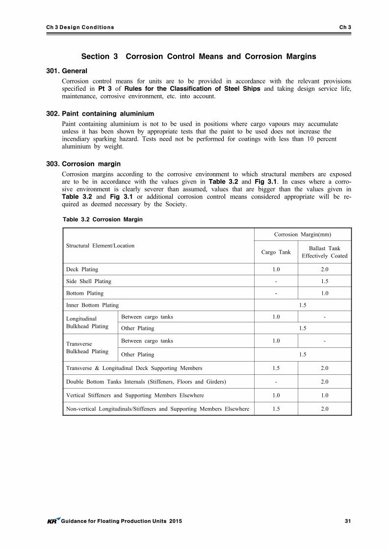
Ch 3 Design Conditions Ch 3
Guidance for Floating Production Units 2015 31
Section 3 Corrosion Control Means and Corrosion Margins
301. General
Corrosion control means for units are to be provided in accordance with the relevant provisions specified in Pt 3 of Rules for the Classification of Steel Ships and taking design service life, maintenance, corrosive environment, etc. into account.
302. Paint containing aluminium
Paint containing aluminium is not to be used in positions where cargo vapours may accumulateunless it has been shown by appropriate tests that the paint to be used does not increase theincendiary sparking hazard. Tests need not be performed for coatings with less than 10 percentaluminium by weight.
303. Corrosion margin
Corrosion margins according to the corrosive environment to which structural members are exposed are to be in accordance with the values given in Table 3.2 and Fig 3.1. In cases where a corro-sive environment is clearly severer than assumed, values that are bigger than the values given in Table 3.2 and Fig 3.1 or additional corrosion control means considered appropriate will be re-quired as deemed necessary by the Society.
Structural Element/Location
Corrosion Margin(mm)
Cargo TankBallast Tank
Effectively Coated
Deck Plating 1.0 2.0
Side Shell Plating - 1.5
Bottom Plating - 1.0
Inner Bottom Plating 1.5
LongitudinalBulkhead Plating
Between cargo tanks 1.0 -
Other Plating 1.5
TransverseBulkhead Plating
Between cargo tanks 1.0 -
Other Plating 1.5
Transverse & Longitudinal Deck Supporting Members 1.5 2.0
Double Bottom Tanks Internals (Stiffeners, Floors and Girders) - 2.0
Vertical Stiffeners and Supporting Members Elsewhere 1.0 1.0
Non-vertical Longitudinals/Stiffeners and Supporting Members Elsewhere 1.5 2.0
Table 3.2 Corrosion Margin
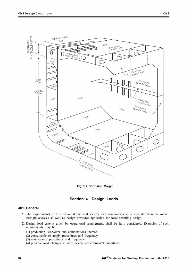
Ch 3 Design Conditions Ch 3
32 Guidance for Floating Production Units 2015
Fig 3.1 Corrosion Margin
Section 4 Design Loads
401. General
1. The requirements in this section define and specify load components to be considered in the overall strength analysis as well as design pressures applicable for local scantling design.
2. Design load criteria given by operational requirements shall be fully considered. Examples of such requirements may be:(1) production, workover and combinations thereof(2) consumable re-supply procedures and frequency(3) maintenance procedures and frequency(4) possible load changes in most severe environmental conditions.
Ch 3 Design Conditions Ch 3
Guidance for Floating Production Units 2015 33
402. Static loads
1. General
(1) The still water loads consist of the permanent and variable functional loads.(2) Permanent functional loads relevant for offshore units are:
(A) mass of the steel of the unit including permanently installed modules and equipment, such as accommodation, helicopter deck, cranes, drilling equipment, flare and production equipment.
(B) mass of mooring lines and risers.(3) Variable functional loads are loads that may vary in magnitude, position and direction during
the period under consideration. (4) Typical variable functional loads are:
(A) hydrostatic pressures resulting from buoyancy(B) crude oil(C) ballast water(D) fuel oil(E) consumables(F) personnel(G) general cargo(H) riser tension(I) mooring forces(J) mud and brine
(5) The variable functional loads utilised in structural design shall normally be taken as either the lower or upper design value, whichever gives the more unfavourable effect.
(6) Variations in operational mass distributions (including variations in tank filling conditions) shall be adequately accounted for in the structural design.
2. Still water hull girder loads
(1) All relevant still water load conditions shall be defined and permissible limit curves for hull girder bending moments and shear forces shall be established for transit and operating condition separately.
(2) The permissible limits for hull girder still water bending moments and hull girder still water shear forces shall be given at least at each transverse bulkhead position and be included in the loading manual.
403. Environmental loads
1. General
Environmental loads are loads caused by environmental phenomena. Environmental loads which may contribute to structural damages shall be considered. Consideration should be given to responses re-sulting from the following listed environmental loads:(1) current loads(2) wind loads(3) wave induced loads(4) Snow and ice loads, when relevant(5) green sea on deck(6) sloshing in tanks(7) slamming (e.g. on bow and bottom in fore and aft ship)(8) vortex induced vibrations (e.g. resulting from wind loads on structural elements in a flare tower).
2. current loads
The current forces on submerged hulls, mooring lines, risers or any other submerged objects asso-ciated with the system are to be in accordance with Rules for the Classification of Mobile Offshore Drilling Units.
3. Wind loads
(1) The wind velocity for the design environmental condition is to be based on the statistical meas-urement wind data for the specific operation site or the analysis and interpretation of wind
Ch 3 Design Conditions Ch 3
34 Guidance for Floating Production Units 2015
measurement data for the specific operation site by weather consultants. It is to be in accord-ance with Rules for the Classification of Mobile Offshore Drilling Units.
(2) The wind velocity for transit, operating and survival condition should normally be not less than the following, unless otherwise documented:(A) Transit and operation conditions: 36 m/s (1 hour period at 10 m above sea level).(B) Survival condition: Site specific.
4. Wave induced loads
(1) The wave loads shall be determined for the site specific environment in which the unit is in-tended to operate.
(2) The following wave induced responses shall be calculated:(A) motions in six degrees of freedom(B) vertical wave induced bending moment at a sufficient number of positions along the hull.
The positions shall include the areas where the maximum vertical bending moment and shear force occur and at the turret position. The vertical wave induced bending moment shall be calculated with respect to the section’s neutral axis
(C) horizontal bending moment(D) accelerations(E) axial forces(F) external sea pressure distribution.
(3) The wave induced bending moments and shear forces may be calculated considering the weather vaning characteristics of the unit.
5. Green sea
(1) The forward part of the deck and areas aft of midship will be particularly exposed to green sea. Short wave periods are normally the most critical.
(2) Appropriate measures should be considered to avoid or minimize the green sea effects on the hull structure, accommodation, deckhouses, topside modules and equipment. These measures in-clude bow shape design, bow flare, bulwarks and other protective structure. Adequate drainage arrangements shall be provided.
(3) Structural members exposed to green sea shall be designed to withstand the induced loads. Green sea loads are considered as local loads.
6. Sloshing loads in tanks
(1) In partly filled tanks sloshing occurs when the natural periods of the tank fluid is close to the periods of the motions of the unit. Factors governing the occurrence of sloshing are:(A) tank dimensions(B) tank filling level(C) structural arrangements inside the tank (wash bulkheads, web frames etc.)(D) transverse and longitudinal metacentric height (GM)(E) draught(F) natural periods of unit and cargo in roll (transverse) and pitch (longitudinal) modes.
(2) The pressures generated by sloshing of the cargo or ballast liquid and the acceptance criteria shall comply with the requirements given in the Pt 12 of Rules for the Classification of Steel Ships.
7. Bottom slamming
Bottom slamming shall comply with the requirements given in the Pt 12 of Rules for the Classification of Steel Ships.
8. Bow impact
The bow region is normally to be taken as the region forward of a position 0.1 L aft of F.P. and above the summer load waterline. The design of the bow structure exposed to impact loads shall be carried out according to the requirements given in the Pt 12 of Rules for the Classification of Steel Ships.
9. Design density of tanks
(1) The following minimum design density of tanks shall be used for the strength and fatigue anal-ysis, unless otherwise agreed by the project:(A) Ballast tanks: 1.025 (seawater)(B) Cargo tanks: 0.9 (C) Fuel oil tanks: 0.9
Ch 3 Design Conditions Ch 3
Guidance for Floating Production Units 2015 35
(D) Mud tanks: 2.5
(E) Brine tanks: 2.2
(F) Fresh water tanks: 1.0 * : For tank testing condition density of seawater 1.025 t/m3 shall be used both for local
strength check and in the cargo hold FE analysis for the harbour condition.(2) The actual tank densities shall be stated on the tank plan.(3) Higher design densities than given in (1) shall be used if specified by the project.
Ch 4 Materials and welding Ch 4
Guidance for Floating Production Units 2015 37
CHAPTER 4 MATERIALS AND WELDING
Section 1 General
101. Application
1. The materials used for important structural members are to be in accordance with Pt 2, Ch 1 of Rules for the Classification of Steel Ships. The steel used for parts supporting heavy loads such as plant facilities, etc. and those parts under tensile loads in the direction across the plate thickness are to be in accordance with Pt 2, Ch 1, 310. of Rules for the Classification of Steel Ships.
2. The welding work of important structural members is to be in accordance with Pt 2, Ch 2 of Rules for the Classification of Steel Ships.
3. Underdeck and hull interface plating or bracket structures attached to the deck or hull should have the same or compatible material grade as the deck or hull structure, respectively.
4. Weld joint design is to be in accordance with Pt 12 of Rules for the Classification of Steel Ships.
5. Mooring system chains, chain parts, wire ropes, fiber ropes, and anchors as well as the windows provided for accommodation spaces are to be in accordance with Pt 4 of Rules for the Classification of Steel Ships, or standards deemed appropriate by the Society.
Ch 5 Hull Construction and Equipment Ch 5
Guidance for Floating Production Units 2015 39
CHAPTER 5 HULL CONSTRUCTION AND EQUIPMENT
Section 1 General
101. General
1. The design and construction of the hull, superstructure and deckhouses for units that are new builds or conversions are to be based on the applicable requirements of design considerations of this guide and not specified in this guide are to be in accordance with the Rules.
2. Design Considerations of this Guide reflects the different structural performance and demands ex-pected for an installation transiting and being positioned at a particular site on a long-term basis compared to that of a vessel engaged in unrestricted seagoing service.
102. Load line
1. A mark designating the maximum allowable draught for loading is to be located in easily visible positions on units as deemed appropriate by the Society or in positions easily distinguishable by the person in charge of liquid transfer operations.
2. The designation of load lines is to comply with the requirements given in the “International Convention on Load Lines, 1996 and Protocol of 1988 relating to the International Convention on Load Lines, 1966”, unless specified otherwise by the relevant flag states or coastal states.
103. Loading manual, stability information and instruction for operation
1. In order to avoid the occurrence of unacceptable stress in unit structures corresponding to all oil and ballast loading conditions and topside modules arrangement and mass and to enable the master or the person-in-charge of loading operations to adjust the loading of cargo and ballast, units are to be provided with loading manuals approved by the Society. Such loading manuals are to at least include the following (1) to (4) items as well as relevant provisions given in Pt 3, Ch 3 of Rules for the Classification of Steel Ships.(1) The loading conditions on which the design of a unit has been based, including the permissible
limits of longitudinal still water bending moments and still water shearing forces.(2) The calculation results of longitudinal still water bending moments and still water shearing
forces corresponding to the loading conditions.(3) The allowable limits of local loads applied to decks, double bottom construction, etc., in cases
where deemed necessary by the Society.(4) The limit values of the loads of mooring lines and riser loads.
2. In addition to Par 1 above, a loading computer that is capable of readily computing longitudinal still water bending moments and still water shearing forces working on units corresponding to all oil and ballast loading conditions and the operation manual for such a computer is to be provided on board.
3. The capability of the loading computer specified in Par 2 above to function as specified in the lo-cation where it is installed is to be confirmed.
4. A stability information booklet approved by the Society is to be provided on board in accordance with Pt 1, Annex 1-2 of Rules for the Classification of Steel Ships. This booklet is to in-clude the results of stability evaluations in representative operating conditions and assumed damage conditions as well as the damage condition of any mooring system equipment as necessary.
5. Instructions for the loading and unloading, and transfer and offloading operations of oil and ballast are to be provided on board. In cases where mooring systems can be isolated, the procedures for isolating and re-mooring are also to be included.
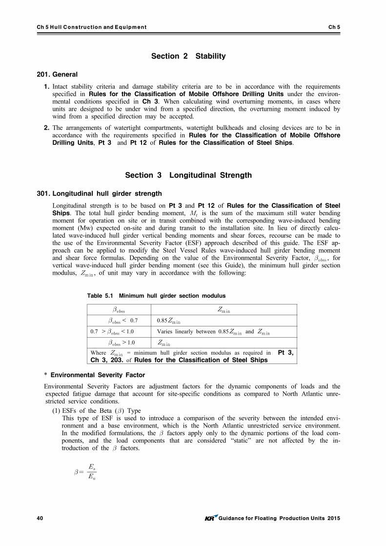
Ch 5 Hull Construction and Equipment Ch 5
40 Guidance for Floating Production Units 2015
Section 2 Stability
201. General
1. Intact stability criteria and damage stability criteria are to be in accordance with the requirements specified in Rules for the Classification of Mobile Offshore Drilling Units under the environ-mental conditions specified in Ch 3. When calculating wind overturning moments, in cases where units are designed to be under wind from a specified direction, the overturning moment induced by wind from a specified direction may be accepted.
2. The arrangements of watertight compartments, watertight bulkheads and closing devices are to be in accordance with the requirements specified in Rules for the Classification of Mobile Offshore Drilling Units, Pt 3 and Pt 12 of Rules for the Classification of Steel Ships.
Section 3 Longitudinal Strength
301. Longitudinal hull girder strength
Longitudinal strength is to be based on Pt 3 and Pt 12 of Rules for the Classification of Steel Ships. The total hull girder bending moment, is the sum of the maximum still water bending moment for operation on site or in transit combined with the corresponding wave-induced bending moment (Mw) expected on-site and during transit to the installation site. In lieu of directly calcu-lated wave-induced hull girder vertical bending moments and shear forces, recourse can be made to the use of the Environmental Severity Factor (ESF) approach described of this guide. The ESF ap-proach can be applied to modify the Steel Vessel Rules wave-induced hull girder bending moment and shear force formulas. Depending on the value of the Environmental Severity Factor, , for vertical wave-induced hull girder bending moment (see this Guide), the minimum hull girder section modulus, min , of unit may vary in accordance with the following:
min < 0.7 0.85min0.7 ><1.0 Varies linearly between 0.85min and min >1.0 minWhere min = minimum hull girder section modulus as required in Pt 3, Ch 3, 203. of Rules for the Classification of Steel Ships
Table 5.1 Minimum hull girder section modulus
* Environmental Severity Factor
Environmental Severity Factors are adjustment factors for the dynamic components of loads and the expected fatigue damage that account for site-specific conditions as compared to North Atlantic unre-stricted service conditions.
(1) ESFs of the Beta () TypeThis type of ESF is used to introduce a comparison of the severity between the intended envi-ronment and a base environment, which is the North Atlantic unrestricted service environment. In the modified formulations, the factors apply only to the dynamic portions of the load com-ponents, and the load components that are considered “static” are not affected by the in-troduction of the factors.
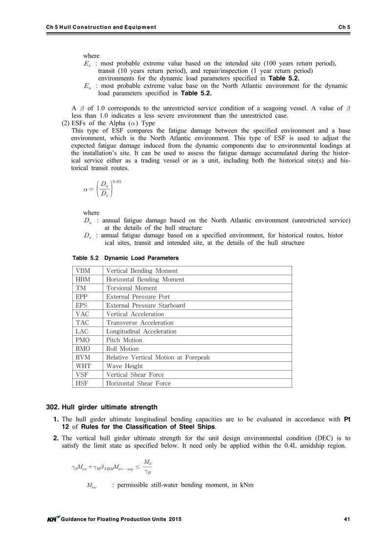
Ch 5 Hull Construction and Equipment Ch 5
Guidance for Floating Production Units 2015 41
where : most probable extreme value based on the intended site (100 years return period),
transit (10 years return period), and repair/inspection (1 year return period)environments for the dynamic load parameters specified in Table 5.2.
: most probable extreme value base on the North Atlantic environment for the dynamicload parameters specified in Table 5.2.
A of 1.0 corresponds to the unrestricted service condition of a seagoing vessel. A value of less than 1.0 indicates a less severe environment than the unrestricted case.
(2) ESFs of the Alpha () Type This type of ESF compares the fatigue damage between the specified environment and a base environment, which is the North Atlantic environment. This type of ESF is used to adjust the expected fatigue damage induced from the dynamic components due to environmental loadings at the installation’s site. It can be used to assess the fatigue damage accumulated during the histor-ical service either as a trading vessel or as a unit, including both the historical site(s) and his-torical transit routes.
where : annual fatigue damage based on the North Atlantic environment (unrestricted service)
at the details of the hull structure : annual fatigue damage based on a specified environment, for historical routes, histor
ical sites, transit and intended site, at the details of the hull structure
VBM Vertical Bending Moment
HBM Horizontal Bending Moment
TM Torsional Moment
EPP External Pressure Port
EPS External Pressure Starboard
VAC Vertical Acceleration
TAC Transverse Acceleration
LAC Longitudinal Acceleration
PMO Pitch Motion
RMO Roll Motion
RVM Relative Vertical Motion at Forepeak
WHT Wave Height
VSF Vertical Shear Force
HSF Horizontal Shear Force
Table 5.2 Dynamic Load Parameters
302. Hull girder ultimate strength
1. The hull girder ultimate longitudinal bending capacities are to be evaluated in accordance with Pt 12 of Rules for the Classification of Steel Ships.
2. The vertical hull girder ultimate strength for the unit design environmental condition (DEC) is to satisfy the limit state as specified below. It need only be applied within the 0.4L amidship region.
≤
: permissible still-water bending moment, in kNm
Ch 5 Hull Construction and Equipment Ch 5
42 Guidance for Floating Production Units 2015
: sagging vertical wave bending moment, in kNm, to be taken as the midship sag-
ging value defined in Pt 12, Sec 7/3.4.1.1 of Rules for the Classification of
Steel Ships.
: sagging vertical hull girder ultimate bending capacity, in kNm, as defined in Pt
12, Appendix A/1.1.1 of Rules for the Classification of Steel Ships.
: ESF for vertical wave-induced bending moment for DEC
: load factor for the maximum permissible still-water bending moment, but not to
be taken as less than 1.0
: load factor for the wave-induced bending moment, but not to be taken as less than
below for the given limits
= 1.3 ( 는 )
= 1.2 ( ≤ ≤ )
: total bending moment, in kNm
= : safety factor for the vertical hull girder bending capacity, but not to be taken as
less than 1.15
Section 4 Structural Design and Analysis of the Hull
401. Structural design of the hull
Design of the hull is to be based on this guide, general hull structures are to be in accordance with the requirements of Pt 12 of Rules for the Classification of Steel Ships.
Where the conditions at the installation site are less demanding than those for unrestricted service that are the basis in hull structure of Rules for the Classification of Steel Ships, the design criteria for various components of the hull structure may be reduced, subject to the limitations indicated below to reflect these differences. However, when the site conditions produce demands that are more severe, it is mandatory that the design criteria are to be increased appropriately. In the application of the modi-fied criteria, no minimum required value of any net scantling is to be less than 85 percent of the value obtained had all the ESF Beta values been set equal to 1.0 (which is the unrestricted service condition). In view of this, for a unit converted from a vessel, where the total bending moment for unrestricted service conditions is used for determination of the minimum required value of any net scantling, the total bending moment should consist of the maximum still water bending moment of the existing vessel and the wave-induced bending moment with all the beta values set equal to 1.0. The loads arising from the static tank testing condition are also to be directly considered in the design. In some instances, such conditions might control the design, especially when the overflow heights are greater than normally encountered in oil transport service, or the severity of environ-mentally-induced load components and cargo specific gravity are less than usual.
1. Hull design for additional loads and load effects
The loads addressed in this Subsection are those required in the design of an installation depending on the length of the installation. Specifically, these loads are those arising from liquid sloshing in hydrocarbon storage or ballast tanks, green water on deck, bow impact due to wave group action above the waterline, bow flare slamming during vertical entry of the bow structure into the water, bottom slamming and deck loads due to on-deck production facilities. All of these can be treated directly by reference to unit. However, when it is permitted to design for these loads and load ef-fects on a site-specific basis, reflect the introduction of the Environmental Severity Factors (ESFs-Beta-type) into the Rule criteria.
2. Superstructures and deckhouses
The designs of superstructures and deckhouses are to comply with the requirements of Pt 12 of Rules for the Classification of Steel Ships. The structural arrangements of Pt 12 of Rules for
Ch 5 Hull Construction and Equipment Ch 5
Guidance for Floating Production Units 2015 43
the Classification of Steel Ships for forecastle decks are to be satisfied.3. Helicopter decks
The design of the helicopter deck structure is to comply with the requirements of Rules for the Classification of Mobile Offshore Drilling Units. In addition to the required loadings defined in Rules for the Classification of Mobile Offshore Drilling Units, the structural strength of the helicopter deck and its supporting structures are to be evaluated considering the DOC and DEC en-vironments, if applicable.
4. Protection of deck openings
The machinery casings, all deck openings, hatch covers and companionway sills are to comply with the requirements of Pt 12 of Rules for the Classification of Steel Ships.
5. Bulwarks, rails, freeing ports, ventilators and portlights
Bulwarks, rails, freeing ports, portlights and ventilators are to comply with the requirements of Pt 12 of Rules for the Classification of Steel Ships.
6. Machinery and equipment foundations
Foundations for equipment subjected to high cyclic loading, such as mooring winches, chain stop-pers and foundations for rotating process equipment, are to be analyzed to verify they provide sat-isfactory strength and fatigue resistance. Calculations and drawings showing weld details are to be submitted to the Bureau for review.
7. Bilge keels
The requirements of bilge keels are to comply with the requirements of Pt 12 of Rules for the Classification of Steel Ships.
8. Sea chests
The requirements of Sea Chests are to comply with the requirements of Pt 12 of Rules for the Classification of Steel Ships.
402. Engineering analyses of the hull structure
1. General
The criteria in this Subsection relate to the analyses required to verify the scantlings selected in the hull design in 401.. Depending on the specific features of the offshore installation, additional analy-ses to verify and help design other portions of the hull structure will be required. Such additional analyses include those for the deck structural components supporting deck-mounted equipment and the hull structure interface with the position mooring system. Analysis criteria for these two sit-uations are given in Section 5.
2. Strength analysis of the hull structure
For installations of 150 m in length and above, two approaches in performing the required strength assessment of the hull structure are acceptable. One approach is based on a three cargo tank length finite element model amidships where the strength assessment is focused on the results obtained from structures in the middle tank. As an alternative, a complete hull length or full cargo block length finite element model can be used in lieu of the three cargo tank length model. Details of the required Finite Element Method (FEM) strength analysis are in accordance with Pt 12 of Rules for the Classification of Steel Ships. When mooring and riser structures are located within the extent of the FE model, the static mass of the mooring lines and risers may be represented by a mass for which gravity and dynamic ac-celerations can be calculated and added to the FEM model. The resulting dynamic loads shall be compared to the mooring and riser analysis results to ensure that the dynamic effects are con-servatively assessed in the hull FE analysis.Generally, the strength analysis is performed to determine the stress distribution in the structure. To determine the local stress distribution in major supporting structures, particularly at intersections of two or more members, fine mesh FEM models are to be analyzed using the boundary displace-ments and load from the 3D FEM model. To examine stress concentrations, such as at intersections of longitudinal stiffeners with transverses and at cutouts, fine mesh 3D FEM models are to be analyzed. The accidental load condition, where a cargo tank is flooded, is to be assessed for longi-tudinal strength of the hull girder consistent with load cases used in damage stability calculations.
Ch 5 Hull Construction and Equipment Ch 5
44 Guidance for Floating Production Units 2015
3. Three cargo tank length model
(1) Structural FE modelThe three cargo tank length FE model is considered representative of cargo and ballast tanks within the 0.4L amidships. Details of the modeling are in accordance with Pt 12 of Rules for the Classification of Steel Ships.
(2) Load ConditionsThe structure analysis for three Cargo Tank Length Model is applied by below load conditions. (A) General Loading Patterns(B) Inspection and repair conditions - Inspection and repair conditions are to be analyzed using
a minimum 1-year return period design operating condition load and a minimum specific gravity of cargo fluid of 0.9.
(C) Transit condition - The transit condition is to be analyzed using the actual tank loading pat-terns in association with the anticipated environmental conditions based on a minimum 10-year return period to be encountered during the voyage.
(3) Load CasesThe structural responses for the still water conditions are to be calculated separately to establish reference points for assessing the wave-induced responses. Additional loading patterns may be required for special or unusual operational conditions or conditions that are not covered by the loading patterns specified in this Guidance. Topside loads are also to be included in the load cases.
4. Alternative approach – cargo block or full ship length model
(1) Structural FE ModelAs an alternative to the three cargo tank length model, the finite element strength assessment can be based on a full length or cargo block length of the hull structure, including all cargo and ballast tanks. All main longitudinal and transverse structural elements are to be modeled. These include outer shell, floors and girders, transverse and vertical web frames, stringers and transverse and longitudinal bulkhead structures. All plates and stiffeners on the structure, includ-ing web stiffeners, are to be modeled. Topside stools should also be incorporated in the model. The modeling mesh and element types used should follow the principles that are described in Pt 12 of Rules for the Classification of Steel Ships. Boundary conditions should be applied at the ends of the cargo block model for dynamic equili-brium of the structure. Detailed local stress assessment using fine mesh models to evaluate highly stressed critical areas are to be in accordance with Pt 12 of Rules for the Classification of Steel Ships.
(2) Loading ConditionsIn the strength analyses of the cargo block or full ship length model, the static on site unit op-erating load cases are to be established to provide the most severe loading of the hull girder and the internal tank structures. The operating load cases found in the Loading Manual and Trim & Stability Booklet provide the most representative loading conditions to be considered for analysis. The static load cases should include as a minimum tank loading patterns resulting in the following conditions.(A) Ballast or minimum draft condition after offloading(B) Partial load condition (33% full)(C) Partial load condition (50% full)(D) Partial load condition (67% full)(E) Full load condition before offloading(F) Transit load condition(G) Inspection and repair conditions(H) Tank testing condition – during conversion and after construction (periodic survey)The tank testing condition is to be considered as a still water condition. The static load cases (A) to (G) will be combined with environmental loading conditions to develop static plus dy-namic load cases that realistically reflect the maximum loads for each component of the structure.
(3) Dynamic LoadingIn quantifying the dynamic loads, it is necessary to consider a range of wave environments and headings at the installation site, which produce the considered critical responses. The static and dynamics of the position mooring and topside module loads contribution shall also be included. Wave loads are to be determined based on an equivalent design wave. The equivalent design
Ch 5 Hull Construction and Equipment Ch 5
Guidance for Floating Production Units 2015 45
wave is defined as a regular wave that gives the same response level as the maximum design response for a specific response parameter. This maximum design response parameter or Dominant Load Parameter is to be determined for the site-specific environment with a 100-year return period, transit environment with a 10-year return period, and inspection and repair con-dition with a 1-year return period. In selecting a specific response parameter to be maximized, all of the simultaneously occurring dynamic loads induced by the wave are also derived. These simultaneous acting dynamic load components and static loads, in addition to the quasi-static equivalent wave loads, are applied to the cargo block model. The Dominant Load Parameters es-sentially refer to the load effects, arising from vessel motions and wave loads, that yield the maximum structural response for critical structural members. Each set of Dominant Load Parameters with equivalent wave and wave-induced loads represents a load case for structural FE analysis. The wave amplitude of the equivalent design wave is to be determined from the maximum de-sign response of a Dominant Load Parameter under consideration divided by the maximum RAO amplitude of that Dominant Load Parameter. RAOs will be calculated using a range of wave headings and periods. The maximum RAO occurs at a specific wave frequency and wave head-ing where the RAO has its own maximum value. The equivalent wave amplitude for a Dominant Load Parameter may be expressed by the following equation:
maxmax
where,
= equivalent wave amplitude of the Dominant Load Parameter
max = maximum response of the Dominant Load Parameter
max = maximum RAO amplitude of the Dominant Load Parameter
Dominant Load Parameter:
Vertical bending moment
Vertical shear force
Horizontal bending moment
Horizontal shear force
External sea pressures
Internal tank pressures
Inertial accelerations
(4) Load CasesLoad cases are derived based on the above static and dynamic loading conditions, Dominant Load Parameters. For each load case, the applied loads to be developed for structural FE analy-sis are to include both the static and dynamic parts of each load component. The dynamic loads represent the combined effects of a dominant load and other accompanying loads acting simultaneously on the hull structure, including external wave pressures, internal tank pressures, deck loads and inertial loads on the structural components and equipment. For each load case, the developed loads are then used in the FE analysis to determine the resulting stresses and other load effects.
5. Fatigue analysis
For all installations of 150 m and above, the extent of fatigue analysis required is indicated in Pt 3 and 12 of Rules for the Classification of Steel Ships. For the three cargo tank length model, the fatigue assessment is to be performed applying Spectral Fatigue Assessment. For the cargo block model, the fatigue assessment is to be performed based on spectral fatigue analysis.The fatigue strength of welded joints and details at terminations located in highly stressed areas and in fatigue prone locations are to be assessed, especially where higher strength steel is used.
Ch 5 Hull Construction and Equipment Ch 5
46 Guidance for Floating Production Units 2015
These fatigue and/or fracture mechanics analyses, based on the combined effect of loading, material properties, and flaw characteristics are performed to predict the service life of the structure and de-termine the most effective inspection plan. Special attention is to be given to structural notches, cutouts, bracket toes, and abrupt changes of structural sections. (1) The cumulated fatigue damage during the transit voyage from the fabrication or previous site for
an existing structure to the operation site is to be included in the overall fatigue damage assessment.
(2) The stress range due to loading and unloading cycles is to be accounted for in the overall fa-tigue damage assessment.
6. Acceptance criteria
The total assessment of the structure is to be performed against the failure modes of material yield-ing, buckling, ultimate strength and fatigue. The reference acceptance criteria of each mode are giv-en in Pt 3 and 12 of Rules for the Classification of Steel Ships.
Section 5 Design and Analysis of Other Major Hull Structural Features
501. General
The design and analysis criteria to be applied to the other pertinent features of the hull structural de-sign are to conform to this Guidance or Rules for the Classification of Steel Ships. For ship-type unit, the hull design will need to consider the interface between the position mooring system and the hull structure or the effects of structural support reactions from deck-mounted (or above-deck) equipment modules, or both. The interface structure is defined as the attachment zone of load transmission be-tween the main hull structure and hull mounted equipment, such as topside module stools, crane pedes-tals and foundations, riser porches, flare boom foundation, gantry foundation, mooring and offloading, etc. The zone includes components of the hull underdeck structures in way of module support stools and foundations, such as deck transverse web frames, deck longitudinals and upper parts of longitudinal and transverse bulkhead structures, as well as foundations of the hull-mounted equipment. These com-ponents of the interface structure should comply with the criteria indicated in 504.. The criteria to be applied for the interface structures are presented below. When it is permitted to base the design for FPSO on site-specific environmental conditions, reference is to be made to 301., 401. and 503. of this Guide regarding how load components can be adjusted.
502. Hull interface structure
The basic scantlings in way of the hull interface structure is to be designed based on the first princi-ple approach and meet the requirements of strength criteria in Rules for the Classification of Mobile Offshore Drilling Units or equivalent national industry standards recognized and accepted, such as API Standards. Welding design of hull interface structure connections is to be developed based on Pt 12, Ch 6, Sec 5 of Rules for the Classification of Steel Ships or a direct calculation approach. Material grades for the above deck interface structure are to be selected as per Rules for the Classification of Mobile Offshore Drilling Units. The material grades for the hull structure components, such as deck and frame structures, are to be selected as per Pt 3 of Rules for the Classification of Steel Ships. The verification of the hull interface structure as defined above is to be performed using direct calculation of local 3-D hull interface finite element models, developed using gross scantlings and analyzed with load conditions and load cases described in the following sections.
1. Position mooring/hull interface modeling
A FEM analysis is to be performed and submitted for review.(1) Turret or SPM Type Mooring System, External to the Installation’s Hull
If the mooring system is of the turret or SPM type, external to the installation’s hull, the fol-lowing applies:(A) Fore end mooring - The minimum extent of the model is from the fore end of the in-
stallation, including the turret structure and its attachment to the hull, to a transverse plane after the aft end of the foremost cargo oil tank in the installation. The model can be con-sidered fixed at the aft end of the model. The loads modeled are to correspond to the worst-case tank loads, seakeeping loads as determined for both the transit condition and the
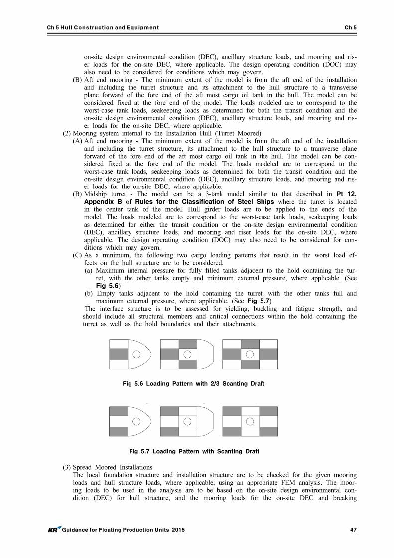
Ch 5 Hull Construction and Equipment Ch 5
Guidance for Floating Production Units 2015 47
Fig 5.7 Loading Pattern with Scanting Draft
Fig 5.6 Loading Pattern with 2/3 Scanting Draft
on-site design environmental condition (DEC), ancillary structure loads, and mooring and ris-er loads for the on-site DEC, where applicable. The design operating condition (DOC) may also need to be considered for conditions which may govern.
(B) Aft end mooring - The minimum extent of the model is from the aft end of the installation and including the turret structure and its attachment to the hull structure to a transverse plane forward of the fore end of the aft most cargo oil tank in the hull. The model can be considered fixed at the fore end of the model. The loads modeled are to correspond to the worst-case tank loads, seakeeping loads as determined for both the transit condition and the on-site design environmental condition (DEC), ancillary structure loads, and mooring and ris-er loads for the on-site DEC, where applicable.
(2) Mooring system internal to the Installation Hull (Turret Moored)(A) Aft end mooring - The minimum extent of the model is from the aft end of the installation
and including the turret structure, its attachment to the hull structure to a transverse plane forward of the fore end of the aft most cargo oil tank in the hull. The model can be con-sidered fixed at the fore end of the model. The loads modeled are to correspond to the worst-case tank loads, seakeeping loads as determined for both the transit condition and the on-site design environmental condition (DEC), ancillary structure loads, and mooring and ris-er loads for the on-site DEC, where applicable.
(B) Midship turret - The model can be a 3-tank model similar to that described in Pt 12, Appendix B of Rules for the Classification of Steel Ships where the turret is located in the center tank of the model. Hull girder loads are to be applied to the ends of the model. The loads modeled are to correspond to the worst-case tank loads, seakeeping loads as determined for either the transit condition or the on-site design environmental condition (DEC), ancillary structure loads, and mooring and riser loads for the on-site DEC, where applicable. The design operating condition (DOC) may also need to be considered for con-ditions which may govern.
(C) As a minimum, the following two cargo loading patterns that result in the worst load ef-fects on the hull structure are to be considered.(a) Maximum internal pressure for fully filled tanks adjacent to the hold containing the tur-
ret, with the other tanks empty and minimum external pressure, where applicable. (See Fig 5.6)
(b) Empty tanks adjacent to the hold containing the turret, with the other tanks full and maximum external pressure, where applicable. (See Fig 5.7)
The interface structure is to be assessed for yielding, buckling and fatigue strength, and should include all structural members and critical connections within the hold containing the turret as well as the hold boundaries and their attachments.
(3) Spread Moored InstallationsThe local foundation structure and installation structure are to be checked for the given mooring loads and hull structure loads, where applicable, using an appropriate FEM analysis. The moor-ing loads to be used in the analysis are to be based on the on-site design environmental con-dition (DEC) for hull structure, and the mooring loads for the on-site DEC and breaking
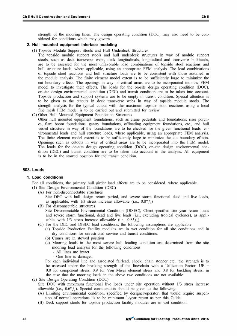
Ch 5 Hull Construction and Equipment Ch 5
48 Guidance for Floating Production Units 2015
strength of the mooring lines. The design operating condition (DOC) may also need to be con-sidered for conditions which may govern.
2. Hull mounted equipment interface modeling
(1) Topside Module Support Stools and Hull Underdeck StructuresThe topside module support stools and hull underdeck structures in way of module support stools, such as deck transverse webs, deck longitudinals, longitudinal and transverse bulkheads, are to be assessed for the most unfavorable load combinations of topside stool reactions and hull structure loads, where applicable, using an appropriate FEM analysis. The load combinations of topside stool reactions and hull structure loads are to be consistent with those assumed in the module analysis. The finite element model extent is to be sufficiently large to minimize the cut boundary effects. The openings in way of critical areas are to be incorporated into the FEM model to investigate their effects. The loads for the on-site design operating condition (DOC), on-site design environmental condition (DEC) and transit condition are to be taken into account. Topside production and support systems are to be empty in transit condition. Special attention is to be given to the cutouts in deck transverse webs in way of topside module stools. The strength analysis for the typical cutout with the maximum topside stool reactions using a local fine mesh FEM model is to be carried out and submitted for review.
(2) Other Hull Mounted Equipment Foundation StructuresOther hull mounted equipment foundations, such as crane pedestals and foundations, riser porch-es, flare boom foundations, gantry foundations, offloading equipment foundations, etc., and hull vessel structure in way of the foundations are to be checked for the given functional loads, en-vironmental loads and hull structure loads, where applicable, using an appropriate FEM analysis. The finite element model extent is to be sufficiently large to minimize the cut boundary effects. Openings such as cutouts in way of critical areas are to be incorporated into the FEM model. The loads for the on-site design operating condition (DOC), on-site design environmental con-dition (DEC) and transit condition are to be taken into account in the analysis. All equipment is to be in the stowed position for the transit condition.
503. Loads
1. Load conditions
For all conditions, the primary hull girder load effects are to be considered, where applicable.(1) Site Design Environmental Condition (DEC)
(A) For non-disconnectable structuresSite DEC with hull design return period, and severe storm functional dead and live loads, as applicable, with 1/3 stress increase allowable (i.e., 0.8*)
(B) For disconnectable structuresSite Disconnectable Environmental Condition (DISEC), Client-specified site year return loads and severe storm functional, dead and live loads (i.e., excluding tropical cyclones), as appli-cable, with 1/3 stress increase allowable (i.e., 0.8*)
(C) For the DEC and DISEC load conditions, the following assumptions are applicable(a) Topside Production Facility modules are in wet condition for all site conditions and in
dry conditions for unrestricted service and transit conditions.(b) Cranes are in stowed position(c) Mooring loads in the most severe hull loading condition are determined from the site
mooring load analysis for the following conditions- All lines are intact- One line is damaged
For each individual line and associated fairlead, chock, chain stopper etc., the strength is to be assessed under the breaking strength of the line/chain with a Utilization Factor, UF = 0.8 for component stress, 0.9 for Von Mises element stress and 0.8 for buckling stress, in the case that the mooring loads in the above two conditions are not available.
(2) Site Design Operating Condition (DOC)Site DOC with maximum functional live loads under site operation without 1/3 stress increase allowable (i.e., 0.6*). Special consideration should be given to the following.(A) Limiting environmental condition, specified by designer/operator, that would require suspen-
sion of normal operations, is to be minimum 1-year return as per this Guide.(B) Deck support stools for topside production facility modules are in wet condition.
Ch 5 Hull Construction and Equipment Ch 5
Guidance for Floating Production Units 2015 49
(C) Crane functional loads are as per API RP 2A and API Spec 2C Practices.(D) Position mooring hull interface
(3) Transit ConditionFor transit (topside production facility in dry condition), it is the shipyard’s and/or designer‘s re-sponsibility to specify the design parameters for the transit condition. There are generally four approaches available.(A) Specified maximum seasonal weather routing condition.(B) Maximum 10-year return response based on the worst environmental conditions and asso-
ciated wave scatter diagram along the transit route.(C) Maximum 10-year return response based on a composite wave scatter diagram(D) North Atlantic service condition, with a minimum 10-year return period, using the IACS
standard wave data where the transit route is not yet defined or finalized.(4) Damage Condition
Damaged Conditions (as applicable) with static deadweight and functional loads only, for a min-imum 1-year return period DOC caused by accidental flooding.
2. Inertial load cases
The DLP values are to be selected for the most unfavorable structural response. Maximum accel-erations are to be calculated at the center of gravity of the most forward and aft and midship top-side production facility modules. The load cases are to be selected to maximize each of the follow-ing DLPs together with other associated DLP values.(1) Max. Vertical Bending Moment(2) Max. Shear Force(3) Max. Vertical Acceleration(4) Max. Lateral Acceleration(5) Max RollAlternatively, the number of load cases can be reduced by assuming that all maximum DLP values occur simultaneously, which is a conservative assumption.
3. Hull girder load cases
As a minimum, the following two hull girder load cases are to be analyzed:(1) Maximum hull girder sagging moment (i.e., generally full load condition)(2) Maximum hull girder hogging moment (i.e., generally ballast, tank inspection or partial loading
condition)
504. Acceptance criteria
1. Yielding checks
(1) For DEC 100-Years Return Periods, Transit 10-Year Return Period and/or North Atlantic Loads(A) For one-stiffener spacing element size FE analysis
(Von Mises) < : plate membrane stresses at element centroids(axial stress) < : bar and beam elements(shear) <
(B) The effects of notches, stress risers and local stress concentrations are to be taken into ac-count when considering load carrying elements. When stress concentrations are considered to be of high intensity in certain elements, the acceptable stress levels will be subject to spe-cial consideration. The following guidance may be used in such circumstances.(a) For mild steel
small area < 1.25 element stress < 1.25
(b) For high-tensile steel small area < 1.0 element stress < 1.0
(2) For DOC (Deadweight + Maximum Functional Loads), with 1-Year Minimum Return Period Loads(A) For one-stiffener spacing element size FE analysis:
< 0.7 : plate membrane stresses at element centroids < 0.6 : bar and beam elements < 0.4
Ch 5 Hull Construction and Equipment Ch 5
50 Guidance for Floating Production Units 2015
ImportanceInspectable and Repairable
Yes No
Non-Critical 3 5
Critical 5 10
Table 5.3 The safety factors
(B) For local detail FE model analyses (localized highly stressed area, 50 × 50 mm approx-imate element size)(a) For mild steel
small area < element stress <
(b) For high-tensile steel small area < element stress <
(3) For Damaged ConditionSame as above for a minimum 1-year return period, except for the following, as applicable(A) For one-stiffener spacing element size FE analysis
< 0.9 : plate membrane stresses at element centroids < 0.8 : bar and beam elements < 0.53
(B) For local detail FE model analyses (localized highly stressed area, 50 × 50 mm approx-imate element size)(a) For mild steel
small area < element stress <
(b) For high-tensile steel small area < element stress <
2. Buckling checks
(1) Bucking criteria in Pt 12 of Rules for the Classification of Steel Ships are to be consid-ered with followings.
(1) Buckling strength to be calculated using gross scantlings(2) Utilization Factor, UF
UF = 0.8 or SF =1.25 for onsite DEC, transit condition and/or North Atlantic conditionUF = 0.6 or SF =1.67 for onsite DOCUF = 0.6 or SF =1.67 for damage conditionUF determined on a case-by-case basis for other special conditions
3. Fatigue calculations
(1) The fatigue calculations are to be carried out for the intended design operating life of the installation. Where the external interface connections are subjected to water immersion, the S-N curves in seawater with (CP) Cathodic Protection or (FC) Free Corrosion are to be used, as applicable. If the simplified fatigue calculation approach is to be used and the long-term Weibull distribution parameter is not available for the hull interface, then a Weibull parameter is to be developed for the specific location under consideration. The safety factors for fatigue life for hull interface connections are to be in accordance with Table 5.3 shown below.
(2) Position Mooring Hull InterfaceStructural members in way of the turret structure or other mooring structure are to be effec-tively connected to the adjacent structure in such a manner as to avoid hard spots, notches and other harmful stress concentrations. Special attention is to be given to cutouts, bracket toes and abrupt changes of structural sections. These areas are considered to be critical to the vessel and are to be free of cracks. The effects of stress risers in these areas are to be determined and minimized. The FE model used to perform the turret/hull integration strength analysis may also be used for the fatigue screening evaluation of the turret/hull interface structure to identify the critical fatigue details using the F or F2 Class S-N curves and appropriate safety factors. The
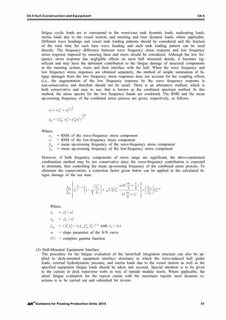
Ch 5 Hull Construction and Equipment Ch 5
Guidance for Floating Production Units 2015 51
fatigue cyclic loads are to correspond to the worst-case tank dynamic loads, seakeeping loads, inertia loads due to the vessel motion, and mooring and riser dynamic loads, where applicable. Different wave headings and vessel tank loading patterns should be considered and the fraction of the total time for each base wave heading and each tank loading pattern can be used directly. The frequency difference between wave frequency stress response and low frequency stress response imposed by mooring lines and risers should be considered. Although the low fre-quency stress response has negligible effects on most hull structural details, it becomes sig-nificant and may have the dominant contribution to the fatigue damage of structural components in the mooring system, risers and their interface with the hull. When the wave frequency and low frequency stress responses are obtained separately, the method of simple summation of fa-tigue damages from the two frequency stress responses does not account for the coupling effects (i.e., the augmentation of the low frequency response by the wave frequency response is non-conservative and therefore should not be used). There is an alternative method, which is both conservative and easy to use, that is known as the combined spectrum method. In this method, the stress spectra for the two frequency bands are combined. The RMS and the mean up-crossing frequency of the combined stress process are given, respectively, as follows.
Where, = RMS of the wave-frequency stress component = RMS of the low-frequency stress component = mean up-crossing frequency of the wave-frequency stress component = mean up-crossing frequency of the low-frequency stress component
However, if both frequency components of stress range are significant, the above-mentioned combination method may be too conservative since the wave-frequency contribution is expected to dominate, thus controlling the mean up-crossing frequency of the combined stress process. To eliminate the conservatism, a correction factor given below can be applied to the calculated fa-tigue damage of the sea state.
Where,
=
=
=
with
= slope parameter of the S-N curve
= complete gamma function
(3) Hull-Mounted Equipment InterfaceThe procedure for the fatigue evaluation of the turret/hull integration structure can also be ap-plied to deck-mounted equipment interface structures in which the wave-induced hull girder loads, external hydrodynamic pressure, and inertia loads due to the vessel motion as well as the specified equipment fatigue loads should be taken into account. Special attention is to be given to the cutouts in deck transverse webs in way of topside module stools. Where applicable, the detail fatigue evaluation for the typical cutout with the maximum topside stool dynamic re-actions is to be carried out and submitted for review.
Ch 5 Hull Construction and Equipment Ch 5
52 Guidance for Floating Production Units 2015
Section 6 Structural Strength for Column-stabilized and Other Type Units
601. General
1. Overall Strength is to be in accordance with the requirements specified in Rules for the Classification of Mobile Offshore Drilling Units.
2. Local Strength is to be in accordance with relevant requirements specified in Rules for the Classification of Mobile Offshore Drilling Units, Pt 3 of Rules for the Classification of Steel Ships, or Pt 12 of Rules for the Classification of Steel Ships. In such cases, applied corrosion margins are to be in accordance with Ch 3.
Section 7 Hull Equipment
701. Mooring systems for temporary mooring
1. The mooring systems for temporary mooring specified in Rules for the Classification of Mobile Offshore Drilling Units need not be fitted. In cases where the Society deems such necessary in consideration of the form of unit operations, the mooring systems for temporary mooring specified in Rules for the Classification of Mobile Offshore Drilling Units are required.
2. In the case of single-point mooring systems to moor shuttle tankers, the chafing chain used ends for mooring lines are to be fitted and are to comply with the following:(1) The chafing chain is to be the offshore chain specified in Pt 4 of Rules for the Classification of Steel Ships, and the chain standard is short lengths (approximately 8 m ) of 76 mm diameter.
(2) The arrangement of the end connections of chafing chains is to comply with any standards deemed appropriate by the Society.
(3) Documented evidence of satisfactory tests of similar diameter mooring chains in the prior six month period may be used in lieu of breaking tests subject to agreement with the Society.
3. Equipment used in mooring systems to moor at jetty etc. in order to install plant or mooring equipment for the mooring support ships and shuttle tankers, except for the equipment specified in Par 2 above, is to be as deemed appropriate by the Society.
702. Guardrails, fenders
1. The guardrails or bulwarks specified in Pt 4 of Rules for the Classification of Steel Ships are to be provided on weather decks. In cases where guardrails will become hindrances to the tak-ing-off and landing of helicopters, means to prevent falling such as wire nets, etc. are to be provided.
2. Suitable fenders fore contact with the gunwales of other ships such as support ships, tug boats, shuttle tankers, etc. are to be provided.
3. Freeing arrangements, cargo ports and other similar openings, side scuttles, rectangular windows, ventilators and gangways are to be in accordance with the requirements for tankers specified in Pt 4 of Rules for the Classification of Steel Ships.
4. Ladders, steps, etc. are to be provided inside compartments for safety examinations as deemed ap-propriate by the Society.
Ch 6 Positioning Systems Ch 6
Guidance for Floating Production Units 2015 53
CHAPTER 6 POSITIONING SYSTEMS
Section 1 General
101. General
1. Units are to be provided with positioning systems complying with the requirements given in this Chapter.
102. Mooring systems
1. Mooring systems are to be sufficiently capable of positioning Units at a specific location against all of the design conditions for positioning as well as all of the safety conditions for systems em-bedded on the seabed and the ships laden with offloaded crude oil from such Units.
2. In the case of mooring systems of Units operated in sea areas where low temperature, freezing, ice formation, etc. are predicted, the effects of such things are to be taken into consideration or appro-priate countermeasures are to be provided.
103. Conditions to be considered for mooring system analysis
1. The various conditions of a Floating Installation which are important for the designer to consider are as follows. (1) Intact Design A condition with all components of the system intact and exposed to an environment as de-
scribed by the design environmental condition (DEC). (2) Damaged Case with One Broken Mooring Line A condition with any one mooring line broken at the design environmental condition (DEC) that
would cause maximum mooring line load for the system. The mooring line subjected to the maximum load in intact extreme conditions when broken might not lead to the worst broken mooring line case. The designer should determine the worst case by analyzing several cases of broken mooring line, including lead line broken and adjacent line broken cases. For a dis-connectable mooring system with quick release system, the mooring analysis for a broken line case may not be required. For unusual (non-symmetric) mooring pattern, mooring analysis for the broken line case for the disconnectable environmental condition may be required. For a sys-tem utilizing the SALM concept, the case with one broken mooring line is not relevant. A case considering loss of buoyancy due to damage of a compartment of the SALM structure should be analyzed for position mooring capability. The loss of thruster power or mechanical failure on thruster-assisted position mooring systems will be considered on a case-by-case basis.
(3) Transient Condition with One Broken Mooring Line A condition with one mooring line broken (usually the lead line) in which the moored in-
stallation exhibits transient motions (overshooting) before it settles at a new equilibrium position. The transient condition can be an important consideration when proper clearance is to be main-tained between the moored installation and nearby structures. An analysis for this condition un-der the design environmental condition (DEC) is required. The effect of increased line tensions due to overshoot upon failure of one mooring line (or thruster or propeller if mooring is pow-er-assisted) should also be considered.
2. The proper clearances between Units and any near-by structures and ships are to also be verified.
3. In the case of SALM, cases considering a loss of buoyancy due to damage of a compartment of the SALM structure should be analyzed for position mooring capability instead of cases with one broken mooring line.
4. Mooring system analysis in combination with the assistance of propulsion systems, thrusters, etc. is to be as deemed appropriate by the Society.
Ch 6 Positioning Systems Ch 6
54 Guidance for Floating Production Units 2015
Section 2 Mooring Analysis
201. General
1. Mooring analysis is to be conducted based on the environmental conditions as specified in Ch 3, Sec 3. Such analysis is to include the evaluations of the mean environmental forces, the extreme response of the Units, and the corresponding mooring line tension.
2. Mooring system analysis as deemed appropriate by the Society is to be carried out for the all pro-spective mooring conditions. The effects due to the draught changes of the Units are to be taken into consideration. In the case of Units mooring to individual periphery facilities, such as CALM, separate from the Units, mooring analysis for the total system, including any periphery facilities, is to be carried out.
3. In case of mooring systems using mooring lines, analysis is to be carried out under the awareness that there is no harmful excessive bend of any lines in way of the contact points between mooring lines and mooring equipment (fairleaders, etc.) fitted on board Units.
4. The mooring systems of Units and the seabed mooring points (anchors, sinkers, piles, etc.) of any periphery facilities for positioning are not to be slid, uplifted, overturned, etc. against any envi-sioned force from the mooring lines. In cases where scouring effects are not considered to be neg-ligible, appropriate consideration is to be taken such as the modification of burial depth, protection against the flow around seabed mooring points, etc.
5. Mooring analysis is to be made under the awareness that the equipment for mooring systems is subjected to steady forces of wind, current and mean wave drift force as well as wind and wave induced dynamic forces. Maximum line tension is to be calculated considering that wind, wave, and current come from unrestricted directions. However, in cases where the data for the specific positioning area of a Units prove a restricted direction of wind, wave and current in that area, cal-culations under such specific directions may be accepted in cases where deemed appropriate by the Society.
6. The maximum offset of a Units and maximum tension of a mooring line is to be calculated. Depending on the analysis objectives, a quasi-static analytical method, or dynamic analytical method as deemed appropriate by the Society may be used for calculations.
7. In the case of deep water operations with large numbers of production risers, mooring system anal-ysis is to take into account riser loads, stiffness, damping, etc. in case where the interaction be-tween Units/mooring systems and riser systems are significant.
202. Mean environmental forces, etc.
1. The calculation of steady forces due to wind and current are to be in accordance with Ch 3, Sec 3.
2. Mean and oscillatory low frequency drift forces may be determined by model tests or using hydro-dynamic computer programs verified against model test results or other data. Mean drift forces to be as deemed appropriate by the Society.
3. Load information is to be prepared based on appropriate analysis, model tests, etc., and such in-formation is to be provided on board.
203. Maximum offset and yaw angle of the installation
1. Maximum offset may be calculated as the sum of the offset due to steady components such as wind, current, and wave (steady drift), and dynamic motion offset due to the dynamic components of forces induced by waves (high and low frequency).
2. The following formula is to be adopted as the standard for calculating maximum offset. In the fol-lowing formula, mean offset and significant single amplitude or maximum amplitude of the max-imum offset obtained from model tests or analysis methods deemed appropriate by the Society are used.
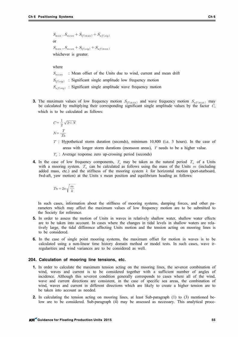
Ch 6 Positioning Systems Ch 6
Guidance for Floating Production Units 2015 55
max max or
max max whichever is greater.
where
: Mean offset of the Units due to wind, current and mean drift
: Significant single amplitude low frequency motion
: Significant single amplitude wave frequency motion
3. The maximum values of low frequency motion max and wave frequency motion max may be calculated by multiplying their corresponding significant single amplitude values by the factor ,which is to be calculated as follows:
∈
: Hypothetical storm duration (seconds), minimum 10,800 (i.e. 3 hours). In the case of
areas with longer storm durations (monsoon areas), needs to be a higher value.
: Average response zero up-crossing period (seconds)
4. In the case of low frequency components, may be taken as the natural period of a Units with a mooring system. can be calculated as follows using the mass of the Units (including added mass, etc.) and the stiffness of the mooring system for horizontal motion (port-starboard, fwd-aft, yaw motion) at the Units s mean position and equilibrium heading as follows:
In such cases, information about the stiffness of mooring systems, damping forces, and other pa-rameters which may affect the maximum values of low frequency motion are to be submitted to the Society for reference.
5. In order to assess the motion of Units in waves in relatively shallow water, shallow water effects are to be taken into account. In cases where the changes in tidal levels in shallow waters are rela-tively large, the tidal difference affecting Units motion and the tension acting on mooring lines is to be considered.
6. In the case of single point mooring systems, the maximum offset for motion in waves is to be calculated using a non-linear time history domain method or model tests. In such cases, wave ir-regularities and wind variances are to be considered as well.
204. Calculation of mooring line tensions, etc.
1. In order to calculate the maximum tension acting on the mooring lines, the severest combination of wind, waves and current is to be considered together with a sufficient number of angles of incidence. Although this severest condition generally corresponds to cases where all of the wind, wave and current directions are consistent, in the case of specific sea areas, the combination of wind, waves and current in different directions which are likely to create a higher tension are to be taken into account as needed.
2. In calculating the tension acting on mooring lines, at least Sub-paragraph (1) to (3) mentioned be-low are to be considered. Sub-paragraph (4) may be assessed as necessary. This analytical proce-
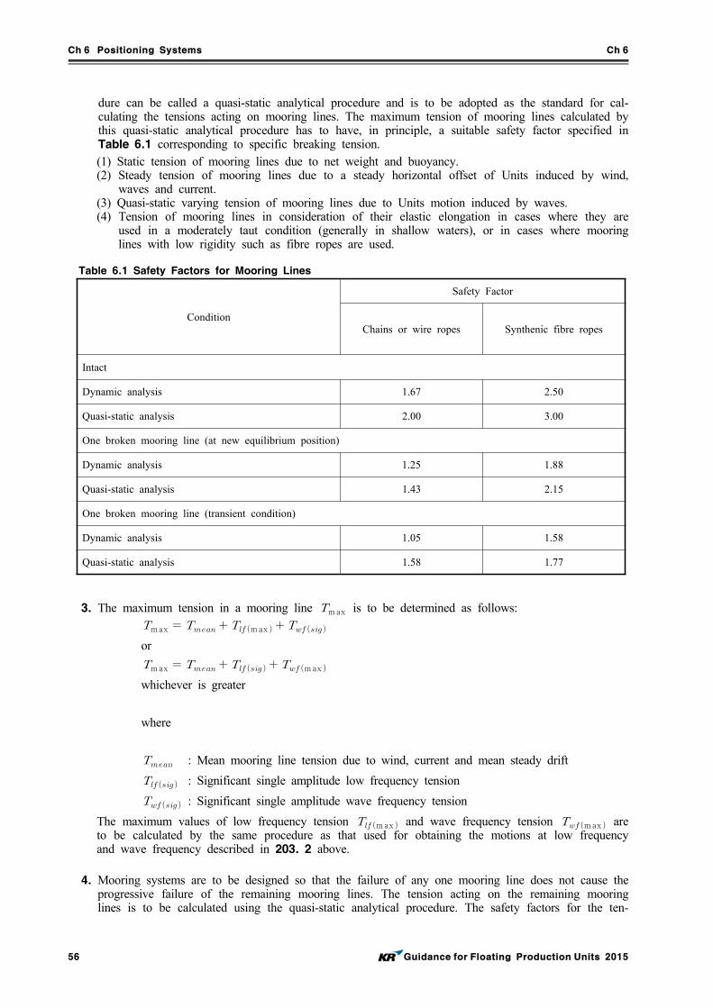
Ch 6 Positioning Systems Ch 6
56 Guidance for Floating Production Units 2015
dure can be called a quasi-static analytical procedure and is to be adopted as the standard for cal-culating the tensions acting on mooring lines. The maximum tension of mooring lines calculated by this quasi-static analytical procedure has to have, in principle, a suitable safety factor specified in Table 6.1 corresponding to specific breaking tension.(1) Static tension of mooring lines due to net weight and buoyancy.(2) Steady tension of mooring lines due to a steady horizontal offset of Units induced by wind,
waves and current.(3) Quasi-static varying tension of mooring lines due to Units motion induced by waves.(4) Tension of mooring lines in consideration of their elastic elongation in cases where they are
used in a moderately taut condition (generally in shallow waters), or in cases where mooring lines with low rigidity such as fibre ropes are used.
Table 6.1 Safety Factors for Mooring Lines
Condition
Safety Factor
Chains or wire ropes Synthenic fibre ropes
Intact
Dynamic analysis 1.67 2.50
Quasi-static analysis 2.00 3.00
One broken mooring line (at new equilibrium position)
Dynamic analysis 1.25 1.88
Quasi-static analysis 1.43 2.15
One broken mooring line (transient condition)
Dynamic analysis 1.05 1.58
Quasi-static analysis 1.58 1.77
3. The maximum tension in a mooring line max is to be determined as follows:max max or
max max whichever is greater
where
: Mean mooring line tension due to wind, current and mean steady drift
: Significant single amplitude low frequency tension
: Significant single amplitude wave frequency tension
The maximum values of low frequency tension max and wave frequency tension max are to be calculated by the same procedure as that used for obtaining the motions at low frequency and wave frequency described in 203. 2 above.
4. Mooring systems are to be designed so that the failure of any one mooring line does not cause the progressive failure of the remaining mooring lines. The tension acting on the remaining mooring lines is to be calculated using the quasi-static analytical procedure. The safety factors for the ten-
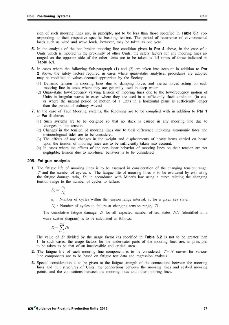
Ch 6 Positioning Systems Ch 6
Guidance for Floating Production Units 2015 57
sion of such mooring lines are, in principle, not to be less than those specified in Table 6.1 cor-responding to their respective specific breaking tension. The period of recurrence of environmental loads such as wind and wave loads, however, may be taken as one year.
5. In the analysis of the one broken mooring line condition given in Par 4 above, in the case of a Units which is moored in the proximity of other Units, the safety factors for any mooring lines ar-ranged on the opposite side of the other Units are to be taken as 1.5 times of those indicated in Table 6.1.
6. In cases where the following Sub-paragraph (1) and (2) are taken into account in addition to Par 2 above, the safety factors required in cases where quasi-static analytical procedures are adopted may be modified to values deemed appropriate by the Society.(1) Dynamic tension in mooring lines due to damping forces and inertia forces acting on each
mooring line in cases where they are generally used in deep water.(2) Quasi-static low-frequency varying tension of mooring lines due to the low-frequency motion of
Units in irregular waves in cases where they are used in a sufficiently slack condition. (in cas-es where the natural period of motion of a Units in a horizontal plane is sufficiently longer than the period of ordinary waves)
7. In the case of Taut Mooring systems, the following are to be complied with in addition to Par 1 to Par 5 above:(1) Such systems are to be designed so that no slack is caused in any mooring line due to
changes in line tension.(2) Changes in the tension of mooring lines due to tidal difference including astronomic tides and
meteorological tides are to be considered.(3) The effects of any changes in the weight and displacements of heavy items carried on board
upon the tension of mooring lines are to be sufficiently taken into account.(4) In cases where the effects of the non-linear behavior of mooring lines on their tension are not
negligible, tension due to non-linear behavior is to be considered.
205. Fatigue analysis
1. The fatigue life of mooring lines is to be assessed in consideration of the changing tension range, and the number of cycles, . The fatigue life of mooring lines is to be evaluated by estimating the fatigue damage ratio, in accordance with Miner's law using a curve relating the changing tension range to the number of cycles to failure.
: Number of cycles within the tension range interval, , for a given sea state.
: Number of cycles to failure at changing tension range, .
The cumulative fatigue damage, for all expected number of sea states (identified in a
wave scatter diagram) is to be calculated as follows:
The value of divided by the usage factor (ɳ) specified in Table 6.2 is not to be greater than 1. In such cases, the usage factors for the underwater parts of the mooring lines are, in principle, to be taken to be that of an inaccessible and critical area.
2. The fatigue life of each mooring line component is to be considered. curves for various line components are to be based on fatigue test data and regression analysis.
3. Special consideration is to be given to the fatigue strength of the connections between the mooring lines and hull structures of Units, the connections between the mooring lines and seabed mooring points, and the connections between the mooring lines and other mooring lines.
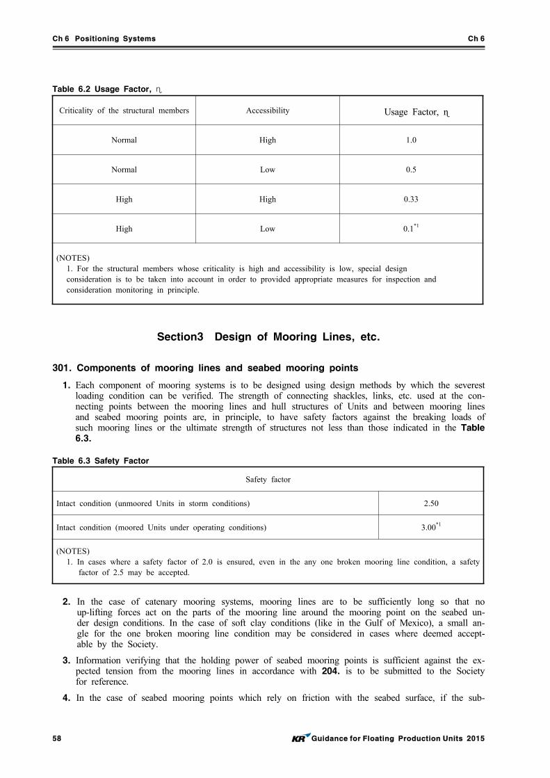
Ch 6 Positioning Systems Ch 6
58 Guidance for Floating Production Units 2015
Table 6.2 Usage Factor, ɳCriticality of the structural members Accessibility Usage Factor, ɳ
Normal High 1.0
Normal Low 0.5
High High 0.33
High Low 0.1*1
(NOTES)1. For the structural members whose criticality is high and accessibility is low, special designconsideration is to be taken into account in order to provided appropriate measures for inspection andconsideration monitoring in principle.
Section3 Design of Mooring Lines, etc.
301. Components of mooring lines and seabed mooring points
1. Each component of mooring systems is to be designed using design methods by which the severest loading condition can be verified. The strength of connecting shackles, links, etc. used at the con-necting points between the mooring lines and hull structures of Units and between mooring lines and seabed mooring points are, in principle, to have safety factors against the breaking loads of such mooring lines or the ultimate strength of structures not less than those indicated in the Table 6.3.
Table 6.3 Safety Factor
Safety factor
Intact condition (unmoored Units in storm conditions) 2.50
Intact condition (moored Units under operating conditions) 3.00*1
(NOTES)1. In cases where a safety factor of 2.0 is ensured, even in the any one broken mooring line condition, a safety
factor of 2.5 may be accepted.
2. In the case of catenary mooring systems, mooring lines are to be sufficiently long so that no up-lifting forces act on the parts of the mooring line around the mooring point on the seabed un-der design conditions. In the case of soft clay conditions (like in the Gulf of Mexico), a small an-gle for the one broken mooring line condition may be considered in cases where deemed accept-able by the Society.
3. Information verifying that the holding power of seabed mooring points is sufficient against the ex-pected tension from the mooring lines in accordance with 204. is to be submitted to the Society for reference.
4. In the case of seabed mooring points which rely on friction with the seabed surface, if the sub-
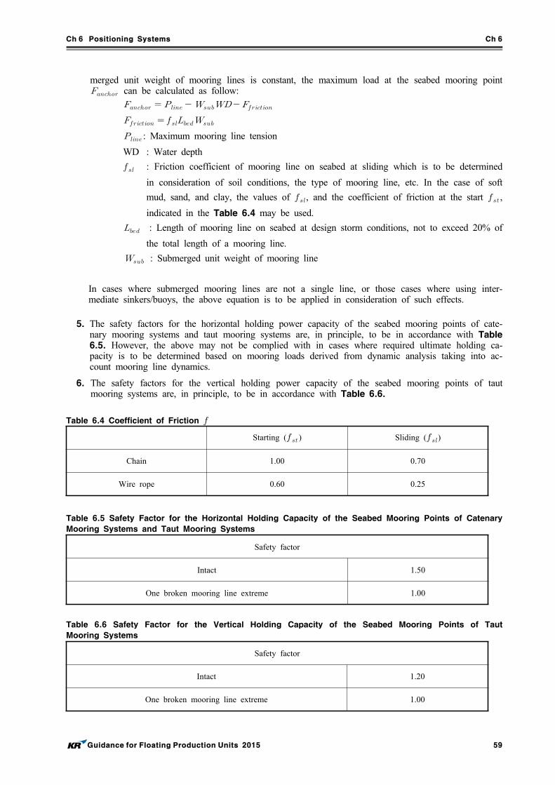
Ch 6 Positioning Systems Ch 6
Guidance for Floating Production Units 2015 59
merged unit weight of mooring lines is constant, the maximum load at the seabed mooring point can be calculated as follow:
: Maximum mooring line tension
WD : Water depth
: Friction coefficient of mooring line on seabed at sliding which is to be determined
in consideration of soil conditions, the type of mooring line, etc. In the case of soft
mud, sand, and clay, the values of , and the coefficient of friction at the start ,
indicated in the Table 6.4 may be used.
: Length of mooring line on seabed at design storm conditions, not to exceed 20% of
the total length of a mooring line.
: Submerged unit weight of mooring line
In cases where submerged mooring lines are not a single line, or those cases where using inter-mediate sinkers/buoys, the above equation is to be applied in consideration of such effects.
5. The safety factors for the horizontal holding power capacity of the seabed mooring points of cate-nary mooring systems and taut mooring systems are, in principle, to be in accordance with Table 6.5. However, the above may not be complied with in cases where required ultimate holding ca-pacity is to be determined based on mooring loads derived from dynamic analysis taking into ac-count mooring line dynamics.
6. The safety factors for the vertical holding power capacity of the seabed mooring points of taut mooring systems are, in principle, to be in accordance with Table 6.6.
Table 6.4 Coefficient of Friction
Starting ( ) Sliding ()
Chain 1.00 0.70
Wire rope 0.60 0.25
Table 6.5 Safety Factor for the Horizontal Holding Capacity of the Seabed Mooring Points of Catenary
Mooring Systems and Taut Mooring Systems
Safety factor
Intact 1.50
One broken mooring line extreme 1.00
Table 6.6 Safety Factor for the Vertical Holding Capacity of the Seabed Mooring Points of Taut
Mooring Systems
Safety factor
Intact 1.20
One broken mooring line extreme 1.00
Ch 6 Positioning Systems Ch 6
60 Guidance for Floating Production Units 2015
Section 4 Mooring Equipment
401. General
1. The equipment of positioning systems is to have sufficient redundancy. In cases where any single unit of equipment of positioning systems is fitted on board Units, special consideration is to be given to the reliability of such equipment and its components. In cases where the failure of any single unit of equipment may lead to loss of positioning capability, an additional set of such equipment will be required as deemed necessary by the Society.
2. Means are to be provided whereby the normal operations of positioning systems can be sustained or restored even though one unit of equipment becomes inoperative. In the case of driving units, special consideration is to be given for preventing loss of function.
3. The prime movers used for positioning systems are to be designed to operate under the static con-ditions given in Ch 9, Sec 1, 102. as well as under the dynamic conditions given below. Deviation from given values may be permitted, taking into consideration the type, size and service conditions, etc. of the Units in cases where deemed appropriate by the Society.(1) In the case of ship type and barge-type Units: Rolling up to 22.5° and simultaneously pitching up to 7.5°(2) In the case of column-stabilized Units: Dynamic inclination up to 22.5° in any direction
402. Chains, wire ropes, etc.
1. Chains, wire ropes or fibre ropes used for mooring systems are to comply with the requirements given in Pt 4, Ch 8, Sec 4 and Sec 5 of Rules for the Classification of Steel Ships or any standards deemed appropriate by the Society. In cases where the Grade R4 chains specified in Pt 4, Ch 8 of Rules for the Classification of Steel Ships or stronger chains are used, special care is to be taken because repairs by welding for any defects, loose studs and corrosion by weld-ing is, in principle, prohibited for such chains.
2. Intermediate sinkers, intermediate buoys and anchors, sinkers, piles, etc. for seabed mooring points are to be as deemed appropriate by the Society.
403. Chain stoppers or windlasses, winches, etc.
1. Individual equipment of mooring systems is, in principle, to be approved by the Society.
2. Chain stoppers used for mooring systems are to have sufficient strength against the breaking strength of the mooring line as deemed appropriate by the Society. The prototypes of chain stop-pers are to be verified to have sufficient strength against the breaking strength of the mooring line. It is to be verified that the stress calculated by structural analysis under the awareness that the mooring line is subjected to design maximum loads does not exceed the specified proof stress of the chain stoppers.
3. Windlasses used for the catenary mooring systems of Units are to comply with the requirements specified in following Sub-paragraph (1) to (3):(1) Each windlass is to be provided with two independent power-operated brakes. Each brake is to
be capable of holding against a static load of at least 50% of braking strength of mooring lines. In cases where deemed appropriate by the Society, one of the brakes may be replaced by a manually operated brake.
(2) Windlasses are to have sufficient dynamic braking capacity to control the normal combination of loads from anchors, mooring lines and anchor handling vessels during the deployment of an-chors at the maximum design pay-out speed of the windlass.
(3) In cases where a power source for a windlass is lost, power-operated braking systems are to be automatically applied and be capable of holding against 50% of the total static braking capacity of the windlass.
4. The means specified in Sub-paragraph (1) to (4) below are to be provided for controlling catenary mooring systems:(1) Each windlass is to be capable of being controlled from a position which provides a good view
Ch 6 Positioning Systems Ch 6
Guidance for Floating Production Units 2015 61
of the operation.(2) Means are to be provided at the windlass control position to monitor mooring line tension and
windlass power load as well as to indicate the amount of mooring line paid out.(3) Indicators for mooring line tension, wind velocity and wind direction at the control station of
each windlass are to be provided at the manned control position.(4) Means of communication are to be provided between essential places for mooring operations
(for example, operating position, wheel house, control room, etc.)5. Means are to be so provided that mooring lines can be released from the Units after any loss of
the main power supply.
6. In the case of laying taut mooring lines, the initial tension in all mooring lines is to be coordi-nated to achieve approximate uniformity. Power equipment capable of adjusting the tension of mooring lines is to be provided as necessary.
7. A tension monitoring system is to be provided for each taut mooring line.
404. Fairleaders
1. In cases where chains are used for mooring lines, the standard length of the part where the chain and fairleader make contact is to be not less than 7 times the chain diameter.
2. In cases where wire ropes or fibre ropes are used for mooring lines, the standard length of the part where the wire rope and fairleader make contact is to be not less than 14 times the wire rope nominal diameter.
3. In the case of arrangements that do not comply with the standards given in Par 1 or Par 2 above, detailed analysis in which the effects of bending loads acting on mooring lines is taken into account is to be carried out. Otherwise, mooring analysis is to be carried out modifying the values of the safety factors given in Table 6.1 upto those values deemed appropriate by the Society.
Section 5 Single Point Mooring Systems
501. Design loads for structures
1. The design of the structure and equipment of single point mooring systems is to consider the se-verest combination of various loads including at least the following. A detailed report about such designs is to be submitted to the Society for reference.(1) Dead loads(2) Dynamic loads due to motion (including rotating motion around turn tables)(3) Mooring loads(4) Fatigue loads
2. In order to consider the design loads acting on turret systems, the loads from mooring lines or ris-ers due to gravity, buoyancy, inertia, and hydraulic forces, etc. are to be taken into account.
502. Structural components
1. Structural components are, in principle, to be in compliance with the codes or standards deemed appropriate by the Society and structural strength is to be evaluated by suitable methods such as FEM, etc.
2. When performing the analysis mentioned in Par 1 above, the allowable stress for von Mises stress is to be 60% of the specified yield strength (not to exceed 72% of the specified tensile strength) of the material used for the part in concern. In the case of transient conditions in the one broken mooring line condition, however, the value of allowable stress may be increased up to but not ex-ceeding 80% of specified yield strength.
3. Structural components are to have sufficient strength against buckling in consideration of their shape, size, surrounding conditions, etc.
4. A fatigue life evaluation is to be carried out for those parts among essential components designated by the Society, such as turret systems, yokes, etc. In such cases, a usage factor of 0.33(0.1 for in-
Ch 6 Positioning Systems Ch 6
62 Guidance for Floating Production Units 2015
accessible areas) is to be used for such evaluations.
5. The structures of the periphery facilities for positioning, the connections between such periphery fa-cilities for positioning and mooring systems and the connections between such periphery facilities for positioning and seabed mooring points are to be as deemed appropriate by the Society.
6. The parts of the hull structures of Units which transmit and dissipate the loads from turrets and yokes (turret bearing parts, etc.) are to be capable of withstanding such loads and are to be suit-ably reinforced.
503. Mechanical components
1. The mechanical components of single point mooring systems(turret bearings, driving mechanisms, various connecting attachments, etc.) are to be in accordance with standards/codes deemed appro-priate by the Society in addition to relevant requirements given in Guidance for single point mooring.
2. The bearings which carry the loads from rotation structures and mooring lines(turret bearings, etc.) are to be designed with a safety factor of not less than 2.0 against the destructive yielding of the bearing surface.
3. Notwithstanding Par 2 above, bearings which do not carry loads are to be as deemed appropriate by the Society.
504. Turret mooring
1. A turret mooring system is one type of station keeping system for a floating installation and can either be installed internally or externally.
2. Both internal and external turret mooring systems will allow the installation to weathervane around the turret.
3. The mooring lines are fixed to the sea bottom by anchors or piles.
4. For an internal turret system, the turret is supported in the installation by a system of bearings.
5. The loads acting on the turret will pass through the bearing system into the installation.
6. Typically, a roller bearing is located near the installation deck level, and radial sliding bearing is located near the keel of the installation. For an external turret mooring system, the installation is extended to attach the turret mooring system at the end of the installation.
7. The loads acting on an internal turret system include those basic loads induced by the mooring lines, risers, gravity, buoyancy, inertia and hydrostatic pressure.
8. Other loads, such as wave slamming and loads resulting from misalignment and tolerance, that may have effect on the turret should also be considered in the design. In establishing the controlling turret design loads, various combinations of installation loading conditions ranging from the full to minimum storage load conditions, wave directions, and both collinear and non-collinear environ-ments are to be considered. The mooring loads and loads applied to the external turret structure are transferred through its bearing system into the installation. The load range and combinations to be considered and analysis methods are similar to those stated for an internal turret mooring system, with additional consideration of environmentally-induced loads on the turret structure.
9. A structural analysis using finite element method is required to verify the sufficient strength of the turret structure.
10. The allowable von Mises stress of the turret structure is to be 0.7 of the yield strength for the operational intact mooring design conditions.
11. The von Mises stress allowed for the design storm intact mooring design conditions and for the design storm one-line broken mooring condition are 90% and 100% of the yield strength, re-spectively, to verify the turret structure mooring attachment locations and supporting structure.
12. A fatigue evaluation of the turret system using a spectral method or other proven approaches is needed to determine the fatigue lives for the turret components.
Ch 6 Positioning Systems Ch 6
Guidance for Floating Production Units 2015 63
Section 6 Anchor Holding Power
601. Generals
Different types of foundation systems used for floating installations are drag anchors, pile anchors, vertically loaded anchors (VLAs) and suction piles. Gravity boxes, grouted piles, templates, etc., may also be used and are considered to be within the scope of classification.
602. Drag anchor
1. For a mooring system with drag anchors, the mooring line length should be sufficiently long such that there is no angle between the mooring line and the seabed at any design condition.
2. For soft clay (in Gulf of Mexico) condition, a small angle for the damaged case with one broken line are to be as deemed appropriate by the Society.
3. Drag anchor holding power depends on the anchor type, as well as the condition of the anchor de-ployed in regard to penetration of the flukes, opening of the flukes, depth of burial, stability of the anchor during dragging, soil behavior of the flukes, etc.
4. The designer should submit to the Society the performance data for the specific anchor type and the site-specific soil conditions for the estimation of the ultimate holding capacity (UHC) of an an-chor design. Because of uncertainties and the wide variation of anchor characteristics, exact holding power is to be determined after the anchor is deployed and test loaded.
5. The maximum load at anchor, is to be calculated, in consistent units, as follows 301. 4
603. Conventional pile
1. Conventional pile anchors are capable of withstanding uplift and lateral forces at the same time.
2. Analysis of the pile as a beam column on an elastic foundation is to be submitted to the Society for review.
3. The analyses for different kinds of soil using representative soil resistance and deflection (p-y) curves are described in the API RP 2A and API RP 2T, as applicable. The fatigue analysis of the pile should be submitted for review.
604. Vertically loaded drag anchors (VLA)
1. VLAs can be used in a taut leg mooring system with approximately a 35° to 45° angle between the seabed and the mooring lines.
2. These anchors are designed to withstand both the vertical and horizontal loads imposed by the mooring line.
3. The structural and geotechnical holding capacity design of the VLA are to be submitted for review. This is to include the ultimate holding capacity and the anchor's burial depth beneath the seabed. Additionally, the fatigue analysis of the anchor and the connectors joining the VLA to the mooring line should be submitted for review.
4. The safety factors of VLA anchors' holding capacity are specified in Table 6-7.
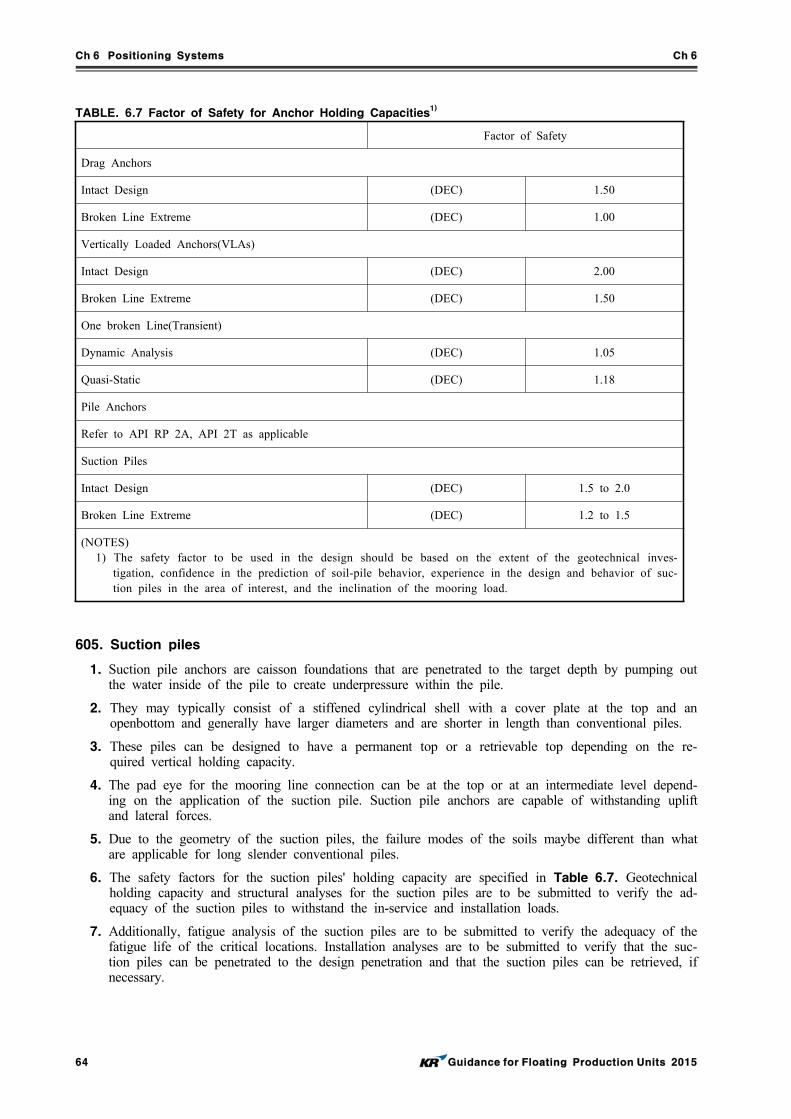
Ch 6 Positioning Systems Ch 6
64 Guidance for Floating Production Units 2015
TABLE. 6.7 Factor of Safety for Anchor Holding Capacities1)
Factor of Safety
Drag Anchors
Intact Design (DEC) 1.50
Broken Line Extreme (DEC) 1.00
Vertically Loaded Anchors(VLAs)
Intact Design (DEC) 2.00
Broken Line Extreme (DEC) 1.50
One broken Line(Transient)
Dynamic Analysis (DEC) 1.05
Quasi-Static (DEC) 1.18
Pile Anchors
Refer to API RP 2A, API 2T as applicable
Suction Piles
Intact Design (DEC) 1.5 to 2.0
Broken Line Extreme (DEC) 1.2 to 1.5
(NOTES)1) The safety factor to be used in the design should be based on the extent of the geotechnical inves-
tigation, confidence in the prediction of soil-pile behavior, experience in the design and behavior of suc-tion piles in the area of interest, and the inclination of the mooring load.
605. Suction piles
1. Suction pile anchors are caisson foundations that are penetrated to the target depth by pumping out the water inside of the pile to create underpressure within the pile.
2. They may typically consist of a stiffened cylindrical shell with a cover plate at the top and an openbottom and generally have larger diameters and are shorter in length than conventional piles.
3. These piles can be designed to have a permanent top or a retrievable top depending on the re-quired vertical holding capacity.
4. The pad eye for the mooring line connection can be at the top or at an intermediate level depend-ing on the application of the suction pile. Suction pile anchors are capable of withstanding uplift and lateral forces.
5. Due to the geometry of the suction piles, the failure modes of the soils maybe different than what are applicable for long slender conventional piles.
6. The safety factors for the suction piles' holding capacity are specified in Table 6.7. Geotechnical holding capacity and structural analyses for the suction piles are to be submitted to verify the ad-equacy of the suction piles to withstand the in-service and installation loads.
7. Additionally, fatigue analysis of the suction piles are to be submitted to verify the adequacy of the fatigue life of the critical locations. Installation analyses are to be submitted to verify that the suc-tion piles can be penetrated to the design penetration and that the suction piles can be retrieved, if necessary.
Ch 6 Positioning Systems Ch 6
Guidance for Floating Production Units 2015 65
8. It is suggested that a ratio of at least 1.5 between the force that would cause uplift of the soil-plug inside of the pile and the effective pile installation force be considered in the penetration analysis.
Section 7 Dynamic Positioning Systems
Dynamic positioning systems used as a means of position keeping are to comply to the require-ments in Pt 9, Ch 4 of Rules for the Classification of Steel Ships.
Ch 7 Hazardous Area Ch 7
Guidance for Floating Production Units 2015 67
CHAPTER 7 HAZARDOUS AREA
Section 1 General
101. Application
1. The requirements given in this Chapter apply to the categorization of hazardous areas, correspond-ing ventilation systems and so on. The hazardous areas as specified may be extended or reduced depending on the actual arrangements in each case, by use of windshields, special ventilation ar-rangements, structural arrangements, etc.
2. The requirements given in this Chapter apply to hazardous areas that handle substances having flash-points not exceeding 60 ℃. Hazardous areas that exclusively handle substances having flash-points exceeding 60 ℃ are to be deemed appropriate by the Society.
3. The requirements not specified in this Guidance are to be in accordance with Pt 7, Ch 1, Sec 11 of Rules for the Classification of Steel Ships and API RP 505.
4. For the purpose of this Chapter :(1) An enclosed space is considered to be a space bounded by bulkheads and decks which may
have doors, windows, of other similar openings.(2) A semi-enclosed location is considered to be a location where natural conditions of ventilation
are notably different from those on open decks due to the presence of structure such as roofs, windbreaks and bulkheads and which are so arranged that the dispersion of gas may not occur.
102. Definition of hazardous area
1. Hazardous areas are all those areas where, due to the possible presence of a flammable atmosphere arising from the drilling operations, the use without proper consideration of machinery or electrical equipment may lead to fire hazard or explosion.
2. Hazardous areas are divided into zones as follows;
Zone 0 : an area in which an explosive gas-air mixture is continuously present or present for long periods.
Zone 1 : an area in which an explosive gas-air mixture is likely to occur in normal operating conditions.
Zone 2 : an area in which an explosive gas-air mixture is not likely to occur, and if it occurs, it will only exist for a short time.
103. Sources of release
A sources of release is point or location from which gases, vapors, or liquid may be released into the atmosphere such that an explosive atmosphere could be formed. Its grade is determined by fre-quency and period as the followings(1) Continuous grade of release A release which is continuous or is expected to occur for long periods.(2) Primary grades of release A release which can be expected to occur periodically or occasionaly during normal operation.(3) Secondary grades of release A release which is not expected to occur in normal operation and it it does occur, is likely to
do so only infrequently and for short periods.
Ch 7 Hazardous Area Ch 7
68 Guidance for Floating Production Units 2015
Section 2 Extent of Hazardous Area
201. Hazardous areas Zone 0
1. The internal spaces of closed tanks for crude oil and gas products
2. The internal spaces of closed pipes for crude oil and gas products including escape gas outlet pipes
3. Outdoor locations within a radius of 0.5 m around crude oil vents
202. Hazardous areas Zone 1
1. Adequately ventilated enclosed or semi-enclosed spaces containing primary grades of release
2. Tanks and cofferdams adjacent to crude oil tanks.
3. Semi-enclosed or enclosed spaces immediately adjacent to crude oil storage tanks
4. Outdoor locations within 1.5 m from the boundaries of the primary grades of release.
5. Inadequately ventilated areas in Zone 2 which are arranged so that gas dispersion may not occur.
6. Outdoor locations within the area with 2.5 m beyond the Zone 0 areas specified in 201. 3.
7. A continuously ventilated (20 air changes per hour) crude oil pump room, provided the failure of ventilation is alarmed in a manned location.
8. Areas on open deck over all crude oil tanks(including all ballast tanks within the crude oil tank block) where structures are restricting the natural ventilation and to the full breadth of the ship plus 3m fore and aft on open deck, up to a height of 2.4m above the deck
203. Hazardous areas Zone 2
1. Adequately ventilated enclosed or semi-enclosed spaces containing secondary grades of release.
2. Outdoor locations within the area with 1.5 m beyond the Zone 1 areas specified in 202. 4.
3. Outdoor locations within the area with 1.5 m beyond the Zone 1 areas specified in 202. 6.
4. Outdoor locations within 3m from the boundaries of ventilation outlets and secondary grades of release.
5. Areas on open deck over all crude oil tanks where unrestricted natural ventilation is guaranteed and to the full breadth of the ship plus 3m fore and aft on open deck, up to a height of 2.4 m above the deck surrounding open or semi-enclosed spaces of Zone 1.
204. Openings, access and ventilation conditions affecting the extent of hazardous zones
1. Except for operational reasons access doors or other openings are not to be provided between the following spaces.(1) A non-hazardous space and a hazardous zone(2) A Zone 2 space and a Zone 1 space
2. Where such access doors or other openings are provided, any enclosed space not referred to under 202. or 203. and having a direct access to any Zone 1 location or Zone 2 location becomes the same zone as the location except that ;(1) An enclosed space with direct access to any Zone 1 location can be considered as Zone 2 :
(A) The access is fitted with a gas-tight door opening into the Zone 2 space, and (B) Ventilation is such that the air flow with the door open is from the Zone 2 space into the
Zone 1 location, and(C) Loss of ventilation is alarmed at a manned station.
(2) An enclosed space with direct access to any Zone 1 location is not considered hazardous if ;(A) The access is fitted with a self-closing gas-tight door forming an air lock. However, in cas-
es where, the Society recognizes that the ventilation system for the space is sufficient to
Ch 7 Hazardous Area Ch 7
Guidance for Floating Production Units 2015 69
prevent the inflow of gases from the Zone 1 space, single self-close gas tight type access doors may be provided. Such doors are to be opened into the space only and no holding devices to keep doors open are to be provided;
(B) The space has ventilation overpressure in relation to the hazardous space, and(C) Loss of ventilation overpressure is alarmed at a manned station.
(3) An enclosed space with direct access to any Zone 2 location is not considered hazardous if ;(A) The access is fitted with a self-closing gas-tight door that opens into the non-hazardous lo-
cation, and(B) Ventilation is such that the air flow with the door open is from the non-hazardous space in-
to the Zone 2 locations, and(C) Loss of ventilation is alarmed at a manned station.
3. Piping systems should be designed to preclude direct communication between hazardous areas of different classifications and between hazardous and non-hazardous areas.
4. Hold-back devices should not be used on self-closing gastight doors forming hazardous area boundaries.
Section 3 Ventilation
301. General
1. Attention is to be given to ventilation inlet and outlet location and airflow in order to minimize the possibility of cross contamination.
2. Inlets are to be located in non-hazardous areas as high and as far away from any hazardous area as practicable.
3. Each air outlet is to be located in an outdoor area which, in the absence of the considered outlet, is of the same or lesser hazard than the ventilated space.
4. Ventilation for hazardous areas is to be completely separate from that used for non-hazardous areas.
302. Ventilation of hazardous areas
1. Where the ventilation duct passes through a hazardous area of a higher level, the ventilation duct should have overpressure in relation to this area and where the ventilation duct passes through a hazardous area of a lower level, the ventilation duct should have under-pressure in relation to this area.
2. The arrangement of ventilation inlet and outlet openings in the space is to be such that the entire space is efficiently ventilated, giving special consideration to location of equipment which may re-lease gas, and to spaces where gas may accumulate.
3. The outlet air from Zone 1 and Zone 2 spaces is to be led in separate ducts to outdoor locations. The internal spaces of such ducts belong to the same Zone as the inlet space.
4. Air inlet ducts designed for constant relative under-pressures are to be rigidly constructed to avoid air leaks.
5. Fans are to be designed so as to reduce the risk that sparks may occur.
6. All areas are to be adequately ventilated. Hazardous enclosed spaces are to be ventilated with un-der-pressure in relation to adjacent non-hazardous locations and non-hazardous enclosed spaces are maintained in overpressure in relation to adjacent hazardous locations. To ensure that a negative pressure condition exists in any enclosed Zone 1 and Zone 2, supply and exhaust fans are to be interlocked so that supply fans cannot be activated without first engaging exhaust fans.
7. Crude oil pump rooms are to be ventilated in accordance with Pt 8, Ch 2, 104. 4 of Rules for the Classification of Steel Ships.
8. Means are to be provided for shutdown of ventilation fans and closing external openings from out-side the spaces served, in the event of fire or detection of combustible or hydrogen or hydrogen sulfide gas.
Ch 8 Fire Protection, Means of Escape and Fire Extinction Ch 8
Guidance for Floating Production Units 2015 71
Ignition source Fuel source
Fired vessels, Electrical equipment, Combustion engines, gas turbines, Waste heat recovery
equipment, Living quarters, Mobile phones, Flares, Lighting, Welding machines, Spark producing hand
tools, Grinding machines, Portable computer, Cutting machinery or torches, Static electricity,
Cameras, Non-Intrinsically Safe Flashlights
Wellheads and manifolds, Process piping, Separators and scubbers, Risers and pipelines, Vents, Gas compressors, Liquid hydrocarbon pumps, Drains, Heat exchangers, Fuel tanks,
Hydrocarbon storage tanks
CHAPTER 8 FIRE PROTECTION, MEANS OF ESCAPEAND FIRE EXTINCTION
Section 1 General
101. Application
1. The requirements not specified in this Guidance are to be in accordance with the requirements for tanker in Pt 8.
2. For fire protection, means of escape and fire detection and extinction of the units, attention is to be paid to the requirements of the national regulations of the country in which the unit is registered.
102. Definition
"H" class divisions are those divisions formed by bulkheads and decks which comply with the following criteria:(1) they are constructed of steel or other equivalent material;(2) they are suitably stiffened;(3) they are insulated with approved non-combustible materials such that the average temperature of
unexposed sides will not rise more than 140 ℃ above the original temperature, nor will the temperature, at any one point, including any joint, rise more than 180 ℃ above the original temperature, within the time listed below during 120-minute hydrocarbon fire tests:
class "H-120" 120 minclass "H-60" 60 minclass "H-0" 0 min
(4) they are constructed as to be capable of withstanding and preventing the passage of smoke and flame to the end of the one-hour standard fire test; and
(5) they are ensured by through tests of prototype bulkheads or decks that the specimen is sub-jected to the temperature corresponding to the curve of hydrocarbon fire time versus temperature described in Interim Hydrocarbon Fire Resistance Test for Elements of Construction for Offshore Installations given by U.K. Department of Energy or Norwegian Petroleum Directorate to ensure that it meets the above requirements for integrity and temperature rise, and to be approved by the Society or organizations deemed appropriate by the Society.
Section 2 Prevention of Fire and Explosion
201. Location and separation of spaces
1. General
(1) Machinery and equipment are to be arranged in accordance with API RP 14J. (2) Equipment items that could become fuel sources in the event of a fire are to be separated from
potential ignition sources by space separation, firewalls or protective walls. The following may be referred for fuel sources and ignition sources.
Ch 8 Fire Protection, Means of Escape and Fire Extinction Ch 8
72 Guidance for Floating Production Units 2015
(3) For the overall safety of personnel and unit, the followings are to be considered in design: (A) Separation of non-hazardous areas from those classified as hazardous areas (B) Minimizing the likelihood of uncontrollable releases of hydrocarbon to the environment (C) Minimizing the spread of flammable liquids and gases which may result in a hazardous
event and facilitating rapid removal of any accumulations(D) Minimizing the probability of ignition (E) Minimizing the consequences of fire and explosions(F) Preventing fire escalation and equipment damage (G) Providing for adequate arrangements for escape and evacuation (H) Effective emergency response (I) Protection of safety systems, critical systems from damage(J) Equipment arrangements are to provide access for inspection and servicing and safe means
of egress from all machinery spaces. (4) In case of a fire onboard the unit, the means of escape is to permit the safe evacuation of all
occupants to a safe area, even when the structure they occupy can be considered lost in a conflagration.
2. Location and separation of production areas
(1) Entrances, air inlets and openings to accommodation spaces are normally not to face production areas.
(2) Control stations are to be located in non-hazardous areas.(3) Areas which contain production systems, gas flare, cold vent, crude oil storage and crude oil
offloading systems are to be arranged in order to provide:(A) Easy access for operation and maintenance(B) Easy access for fire fighting(C) Adequate ventilation(D) Minimized explosion overpressure in the case of ignited gas release
(4) The outlets of gas disposal systems, e.g. flares, cold vents or pressure relief valves or from large engine exhausts are to be led to areas where radiation, heat or gases will not be a hazard to the unit, personnel or equipment.
(5) Flare and vent systems are to be in accordance with the standards deemed appropriate by the Society. The radiant heat intensities or emissions from flares and vents are not to exceed the following limits:(A) In areas where emergency action lasting up to 1 minute may be required by personnel with-
out shielding, but with appropriate clothing: 6.3 kWm(B) In areas where emergency action lasting several minutes may be required by personnel with-
out shielding, but with appropriate closing: 4.7 kWm(C) At any location where personnel are continuously exposed: 1.6 kWm(D) Temperature rating of electrical and mechanical equipment(E) At any point on the unit where the gas plumes from vents could be ignited or personnel
could come into contact with such gas: 60% LEL
3. Location and separation of crude oil areas
(1) Separation of crude oil tanks is to taken as follows;(A) Crude oil tanks are to be isolated from non-hazardous areas by cofferdams, pump rooms, oil
bunker tanks or ballast tanks.(B) Crude oil tanks are to be isolated from machinery spaces by cofferdams, pump-rooms, oil
bunker tanks or ballast tanks. The lower portion of the pump-room may be recessed into machinery spaces of category A to accommodate pumps, provided that the deck head of the recess is in general not more than one third of the moulded depth of the unit above the keel.
(2) Entrances, air inlets and openings to accommodation, service and machinery spaces and control stations are not to face crude oil areas. They are to be located on end bulkheads not facing crude oil areas and/or on the outboard sides of superstructures or deckhouses at a distance of at least 4% of the Length (L) of the unit as specified in Ch 1, 202. of Rules for the Classification of the Mobile Offshore Drilling Units. but not less than 3m from the end of superstructures or deckhouses facing crude oil areas. This distance, however, need not exceed 5m. Furthermore, the following necessary conditions apply to boundaries facing crude oil areas:(A) Bolted plates for removal of machinery may be fitted in such boundaries. Signboards giving
instruction that such plates are to be kept closed unless the unit is gas-free are to be posted
Ch 8 Fire Protection, Means of Escape and Fire Extinction Ch 8
Guidance for Floating Production Units 2015 73
on board.(B) Windows in navigation bridges may be accepted on the condition that such windows are
non-opening types and constructed to "H-60" class standard.(3) Mooring systems with combustion machinery are to be located outside of hazardous areas unless
special precautions to avoid any risks of ignition during normal operations and emergency re-leases are provided.
(4) Chain lockers and chain pipes are to be arranged in non-hazardous areas.4. Crude oil tank venting is to comply with the following requirements;
(1) Tanks are to have means for inert gas, gas-freeing and venting in accordance with the appli-cable parts of Pt 8 of Rules for the Classification of Steel Ships.
(2) Hatches, openings for ventilation, ullage plugs or other deck openings for crude oil tanks are not to be arranged in enclosed compartments.
5. Location and Separation of Pump rooms, cofferdams and pipe tunnels(1) Cofferdams are to be of sufficient size for easy access to parts, and they are to cover the en-
tire adjacent tank bulkhead. Minimum distance between bulkheads is to be 600 mm .(2) In cases where non-hazardous spaces and crude oil tank meet in corner to corner configurations,
diagonal plates may be accepted as cofferdams. Such cofferdams are to be:(A) Ventilated if accessible(A) Filled with a suitable compound if not accessible
(3) Pipe tunnels are to have ample space for pipe inspections.(4) There are to be no connections between pipe tunnels and engine rooms. Access to pipe tunnels
is normally to be made through pump rooms, similar hazardous areas or from open decks. Access openings from crude oil pump rooms are to be provided with watertight closures.(A) in addition to the bridge operation, the watertight door shall be capable of being manually
closed from outside the pump-room entrance; and (B) the watertight door shall be kept closed during normal operations of the unit except when
access to the pipe tunnel is required.
6. Wellhead areas
(1) Wellhead areas are to be separated or protected from sources of ignition and mechanical damage.
(2) "A-0" firewalls around wellheads are to be used to provide protection from potential uncon-trolled flow from wellheads with shut-in pressures exceeding 42 kgcm.
7. Fired vessels
(1) Fired vessels(glycol reboilers, etc.) are to be installed away from wellheads and other hydro-carbon processing and storage equipment. If it is not be possible to comply to the above re-quirement, particularly when the space of the process area is limited, causing fired vessels to be located in the unfired process areas, then the fired vessel is to be surrounded on all sides by a minimum of "A-0" class firewall.
(2) For direct fired vessels such as produced fluid heater treater that is considered both as fuel and ignition source, a minimum of "A-0" rated firewall is to be provided as described in (1), re-gardless of where the unit is installed within the production or process areas.
Ch 8 Fire Protection, Means of Escape and Fire Extinction Ch 8
74 Guidance for Floating Production Units 2015
Section 3 Suppression of Fire
301. Containment of fire
1. General
(1) Exterior boundaries of superstructures and deckhouses enclosing accommodation and including any overhanging decks which support such accommodation, are to be constructed of steel and insulated to "H-60" class for the whole of the portions which face the crude oil area and the production area and on the outward sides for a distance of 3 m from the end boundary facing the crude oil area and production area. In cases where there is a minimum of 30 separation from the crude oil areas and the production areas, however, "A-0" class deemed appropriate by the Society may be applied.
(2) Bulkheads between crude oil pump rooms and machinery spaces are to be Class A, and are to have no penetrations which are less than Class A-0. However, bulkheads and decks between crude oil pump-rooms and machinery spaces of category A may be penetrated by crude oil pump shaft glands and similar glanded penetrations, provided that gas tight seals with efficient lubrication or other means of ensuring the permanence of the gas seal are fitted in way of the bulkheads or deck.
(3) Windows are not to be installed in bulkheads and decks between machinery spaces and crude oil pump rooms.
(4) Skylights to crude pump rooms are to be made of steel, but are not to be fitted with glass. Such skylights are to be capable of being closed from outside pump rooms.
2. Methods of protection in accommodation and service spaces and control stations are to adopt only method IC as defined in Pt 8, Ch 3, 301. 3 (1) (A) of Rules for the Classification of Steel Ships.
3. Fire integrity of bulkheads and decks
(1) The minimum fire integrity of bulkheads and decks shall be as prescribed in Tables 8.1 and 8.2.
(2) For determining the appropriate fire integrity standards to be applied to divisions between ad-jacent spaces, such spaces are classified according to their fire risk as shown in categories ① to ⑫ below. The title of each category is intended to be typical rather than restrictive.
① Control stations spaces as defined in Ch 1, 211. of Rules for the Classification of Mobile Offshore Drilling Unit (A station where the emergency power source is located is not considered.)
② Corridors corridors and lobbies.
③ Accommodation spaces Spaces used for public spaces, cabins, offices, hospitals, cinemas, games and hobby rooms and similar spaces, excluding corridors, lavatories and pantries containing no cooking appliances.
④ Stairways Iinterior stairways, lifts and escalators (other than those wholly contained within the
machinery spaces) and enclosures thereto. In this connection a stairway which is en-closed only at one level is to be regarded as part of the space from which it is not separated by a fire door.
⑤ Service spaces (low risk) Lockers, store-rooms and working spaces in which flammable materials are not stor-ed, drying rooms and laundries.
⑥ Machinery spaces of category A Spaces as defined in Pt 8, Ch 1, 103. 31 of Rules for the Classification of Steel Ships.
⑦ Other machinery spaces All other machinery spaces than machinery spaces of Category A, containing propel-ling machinery, boilers, oil fuel units, steam and internal combustion engines, gen-erators and major electrical machinery, oil filling stations, refrigerating, stabilizing, ventilating and air-conditioning machinery and similar spaces, including trunks to such spaces.
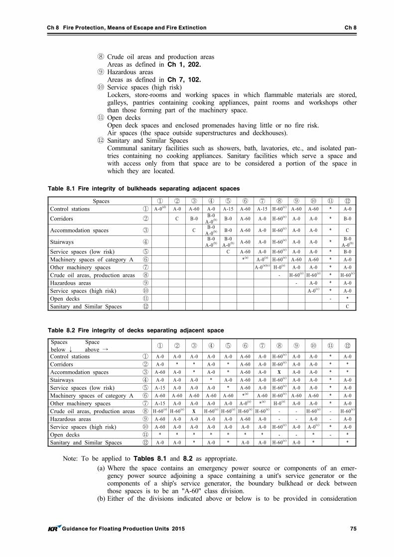
Ch 8 Fire Protection, Means of Escape and Fire Extinction Ch 8
Guidance for Floating Production Units 2015 75
⑧ Crude oil areas and production areasAreas as defined in Ch 1, 202.
⑨ Hazardous areasAreas as defined in Ch 7, 102.
⑩ Service spaces (high risk) Lockers, store-rooms and working spaces in which flammable materials are stored, galleys, pantries containing cooking appliances, paint rooms and workshops other than those forming part of the machinery space.
⑪ Open decks Open deck spaces and enclosed promenades having little or no fire risk. Air spaces (the space outside superstructures and deckhouses).
⑫ Sanitary and Similar SpacesCommunal sanitary facilities such as showers, bath, lavatories, etc., and isolated pan-tries containing no cooking appliances. Sanitary facilities which serve a space and with access only from that space are to be considered a portion of the space in which they are located.
Spaces ① ② ③ ④ ⑤ ⑥ ⑦ ⑧ ⑨ ⑩ ⑪ ⑫Control stations ① A-0(d) A-0 A-60 A-0 A-15 A-60 A-15 H-60(e) A-60 A-60 * A-0
Corridors ② C B-0B-0
A-0(b) B-0 A-60 A-0 H-60(e) A-0 A-0 * B-0
Accommodation spaces ③ C B-0
A-0(b) B-0 A-60 A-0 H-60(e) A-0 A-0 * C
Stairways ④B-0
A-0(b)B-0
A-0(b) A-60 A-0 H-60(e) A-0 A-0 *B-0
A-0(b)
Service spaces (low risk) ⑤ C A-60 A-0 H-60(e) A-0 A-0 * B-0
Machinery spaces of category A ⑥ *(a) A-0(a) H-60(e) A-60 A-60 * A-0
Other machinery spaces ⑦ A-0(a)(c) H-0(e) A-0 A-0 * A-0
Crude oil areas, production areas ⑧ - H-60(e) H-60(e) * H-60(e)
Hazardous areas ⑨ - A-0 * A-0
Service spaces (high risk) ⑩ A-0(c) * A-0
Open decks ⑪ - *
Sanitary and Similar Spaces ⑫ C
Table 8.1 Fire integrity of bulkheads separating adjacent spaces
Spaces Space below ↓ above →
① ② ③ ④ ⑤ ⑥ ⑦ ⑧ ⑨ ⑩ ⑪ ⑫
Control stations ① A-0 A-0 A-0 A-0 A-0 A-60 A-0 H-60(e) A-0 A-0 * A-0
Corridors ② A-0 * * A-0 * A-60 A-0 H-60(e) A-0 A-0 * *
Accommodation spaces ③ A-60 A-0 * A-0 * A-60 A-0 X A-0 A-0 * *
Stairways ④ A-0 A-0 A-0 * A-0 A-60 A-0 H-60(e) A-0 A-0 * A-0
Service spaces (low risk) ⑤ A-15 A-0 A-0 A-0 * A-60 A-0 H-60(e) A-0 A-0 * A-0
Machinery spaces of category A ⑥ A-60 A-60 A-60 A-60 A-60 *(a) A-60 H-60(e) A-60 A-60 * A-0
Other machinery spaces ⑦ A-15 A-0 A-0 A-0 A-0 A-0(a) *(a) H-0(e) A-0 A-0 * A-0
Crude oil areas, production areas ⑧ H-60(e) H-60(e) X H-60(e) H-60(e) H-60(e) H-60(e) - - H-60(e) - H-60(e)
Hazardous areas ⑨ A-60 A-0 A-0 A-0 A-0 A-60 A-0 - - A-0 - A-0
Service spaces (high risk) ⑩ A-60 A-0 A-0 A-0 A-0 A-0 A-0 H-60(e) A-0 A-0(c) * A-0
Open decks ⑪ * * * * * * * - - * - *
Sanitary and Similar Spaces ⑫ A-0 A-0 * A-0 * A-0 A-0 H-60(e) A-0 * *
Table 8.2 Fire integrity of decks separating adjacent space
Note: To be applied to Tables 8.1 and 8.2 as appropriate. (a) Where the space contains an emergency power source or components of an emer-
gency power source adjoining a space containing a unit's service generator or the components of a ship's service generator, the boundary bulkhead or deck between those spaces is to be an "A-60" class division.
(b) Either of the divisions indicated above or below is to be provided in consideration
Ch 8 Fire Protection, Means of Escape and Fire Extinction Ch 8
76 Guidance for Floating Production Units 2015
of Ch 10, 201. 9 (3) and (5) of Rules for the Classification of the Mobile Offshore Drilling Units.
(c) Where spaces are of the same numerical category and superscript (c) appears, a bulkhead or deck of rating shown in the table is only required when the adjacent spaces are for a different purpose, e.g. in category ⑩. A galley next to a galley does not require a bulkhead but a galley next to a paint room requires an "A-0" bulkhead.
(d) Bulkheads separating the navigating bridge, chartroom and radio room from each other may be an "B-0" rating.
(e) If the results of a Risk Analysis or Fire Load Analysis (reviewed and accepted by the Society) justify such, an "A-60" fire division may be used in lieu of an "H-60" bulkhead. An "A-0" wall used in conjunction with a water curtain system designed to provide a density of at least 6.1 m min of exposed surface area may be used as an equivalent means of meeting the "A-60" class division.
* Where an asterisk appears in the tables, the division is required to be of steel or other equivalent material but is not required to be of "A" class standard. However, where a deck, except an open deck, is penetrated for the passage of electric cables, pipes and vent ducts, such penetrations should be made tight to prevent the passage of flame and smoke.
- Where "-" appears in the table, the division need not be of "A", "B" nor "C" class divisions.
X Where an "X" appears in the table, the configuration is not allowed.
302. Fire fighting systems
1. Water supply systems
(1) Piping(A) Water fire fighting systems are to be capable of maintaining a continuous supply in the
event of damage to water piping. Piping is to be arranged so that the supply of water could be from two different sources. Isolation valves are to be provided such that damage to any part of the system would result in the loss in use of the least possible number of hydrants, water spray branches, or foam water supplies.
(B) Materials readily rendered ineffective by heat shall not be used for fire mains and hydrants unless adequately protected.
(2) Fire pumps(A) There are to be at least two independently driven and self-priming fire pumps. The fire
pumps are to be located such that a fire in any one location will not render both fire pumps inoperable. One of the two pumps is to be designated as the primary fire pump, and the other as the standby fire pump. At least one of the pumps is to be diesel engine driv-en, unless the emergency power supply can supply the load for an electric motor driven pump.
(B) The primary and standby fire pumps are each to be capable of supplying the maximum probable water demand for the protected space. The maximum probable water demand is the total water requirement for protection of the largest single fire area plus two jets of fire wa-ter at a pressure of at least 0.35 MPa. Multiple pump installations will be considered in lieu of a single primary and/or standby pump installation, provided they are arranged in such a manner that a fire in one area would not reduce the available supply of fire water required to handle that fire, or such that if the largest pump is out of service for maintenance, the available supply of water would not be reduced below the maximum probable water demand. A means is to be provided for periodic testing of each fire pump.
(C) The maximum probable water demand includes the water supply to the water spray system for a single fire on the production deck, the water supply to the deck foam system and plus two jets of fire water.
(D) To determine the maximum probable water demand, the fire risk areas on the production deck may be divided into fire zones. If a fire is being considered in a single zone, the wa-ter supply for the water spray system is to be sufficient for that zone and adjacent zones. The water spray system requirement may be ignored for adjacent zones if these zones are separated by a firewall (no less than A-60). The system emergency shutdown and the equip-ment blowdown may be considered a safe alternative to the water spray for low hydro-
Ch 8 Fire Protection, Means of Escape and Fire Extinction Ch 8
Guidance for Floating Production Units 2015 77
carbon liquid inventory equipment such as the gas compressor units. (E) Pumps for process water spray systems are to be provided with automatic starting. In addi-
tion to the pump automatic starting requirement, pump driver starters are to be provided with means for local and remote operation from a permanently manned station or a fire control station. Pump discharge control valves, used to separate the section of the firewater service system and the fire pumps, are to be fitted in an easily accessible location outside of the pump space. Diesel-driven fire pumps may be provided with electrical or pneumatic starting and control systems.
(F) Pump drivers may include diesel engines, natural gas engines, or electric motors. The pump drivers are to be in general accordance with 5.2 (4) (a), (b) and (c) of API RP 14G, with respect to their types and installation requirements. Where diesel and natural gas engine fire pumps are considered, the arrangements are to comply with requirements of Ch 11, 403. 4. For electrical motor-driven fire pumps, the arrangements are to comply with requirements of Ch 10, 103.
(G) Fuel systems are to comply with the requirements of Ch 11, 402. 5. Fuel supply for diesel engines is to be sufficient for 18 hours operation.
(3) Fire water station(A) Fire-water stations are to be located so that each station will be readily accessible in the
event of a fire. All materials that comprise the fire water station and the access to fire wa-ter stations are to be of steel or equivalent material. Firewater stations are to be located on the perimeter of process areas. The stations and their arrangements are to provide at least two jets of water not emanating from the same fire station to reach any part of the pro-duction facility that may be exposed to fire.
(B) Fire monitors are to be sized for a minimum flow of 1,892 min at 0.72 MPa . Nozzles are to be of at least 12 mm. fire monitors and nozzles are to be of corrosion-resistant materials or be protected with a suitable coating to protect the equipment from the offshore environment. All nozzles are to incorporate means for a shut-off and be of dual-purpose type(i.e., spray/jet).
(C) Fire hoses located on the production deck are to be of a non-collapsible type mounted on reels, and are to be certified by a recognized testing laboratory as being constructed of non-perishable material to recognized standards. The hoses are to be of material resistant to oil and chemical deterioration, mildew and rot, and exposure to the offshore environment. Hoses are to be sufficient in length to project a jet of water to any location in the areas where they may be required to be used. Each hose is to be provided with a nozzle and the necessary couplings. The maximum length of hose reels used on the production deck may be as long as 30 m . All indoor fire stations are to be provided with collapsible hoses and the maximum length of collapsible hoses is not to exceed 23 m .
(4) Water deluge system for process equipment (A) A fixed water spray system is to be installed for the process equipment to keep the process
equipment cool and reduce the risk of escalation of a fire. Water spray systems are to be capable of being actuated both automatically by a fire detection system and manually. Installations are generally to be in accordance with NFPA Standard 15, or other equivalent standard such as API RP 2030. Deluge isolation valves are to be located in a safe area and outside the fire zone they protect. Consideration will be given to the use of manual actua-tion alone, provided that the combined volume of process and storage vessels is less than 15 m, and the unit is manned on a 24-hour basis and the manual actuation station is read-ily accessible.
(B) Process equipment, including hydrocarbon vessels, heat exchangers, fired heaters and other hydrocarbon handling systems, are to be protected with a water spray system. The system is to be designed to provide a water density of 10.2 m min of exposed surface area for un-insulated vessels, or 6.1 m min of exposed surface area for insulated vessels. Process equipment support structure, but not secondary deck structure members, is to be protected with a water spray system designed to provide a water density of 4.1 m min . Alternatively, the use of intumescent coatings may be acceptable in protecting the support structure subject to approval of the Society. The condition of the coatings will be the sub-ject of surveyor inspection at normal survey intervals. For gas-handling equipment, such as gas compressor skids, where the hydrocarbon liquid inventory is kept minimal, a water spray system is not required if the equipment is provided with an automatic blowdown upon the process shutdown.
Ch 8 Fire Protection, Means of Escape and Fire Extinction Ch 8
78 Guidance for Floating Production Units 2015
(C) Wellheads with maximum shut-in tubing pressures exceeding 4.1 MPa are to be protected with a water spray system. The water spray system is to be designed to provide a minimum water density of 20.4 m min based on the protection of wellheads, ESD valves, and crit-ical structural components including the firewall.
(D) Internal turrets with swivel pressure ratings exceeding 4.1 MPa are to be protected with a water spray system. Turret areas, including the swivel and its associated equipment, are to be protected by a water spray system designed to provide a minimum water density of 20.4 m min .
2. Foam systems for crude storage tanks
(1) Deck foam systems are to be provided for all facilities storing crude oil in integral storage tanks, in accordance with Pt 8, Ch 3, 407. of Rules for the Classification of Steel Ships.
(2) Where process equipment is located or supported above crude storage areas such that deck foam system application might be obstructed by steel supporting members, fixed foam systems may be considered as an alternative.
3. Fixed fire extinguishing systems
(1) A fixed fire fighting system is to be provided in each enclosed space containing the following equipment: (A) Internal combustion machinery, including diesel and gas engines, having a total power output
of not less than 750 kW(B) Oil fule units, oil or gas-fired boilers and other processes such as incinerators and inert gas
generators (C) Settling tanks for boilers (D) Gas compressors (E) Transfer pumps for crude oil or flammable liquid having flash point of less than 60°C. If a
fixed foam system is to be used for the methanol pump room and methanol tank space, the type of foam selected is to be suitable for use with methane.
(2) A fixed fire extinguishing system required by (1) may be any of the following systems: (A) a fixed gas fire-extinguishing system complying with Pt 8, Ch 3, 403. of Rules for the Classification of Steel Ships;
(B) a fixed high-expansion foam fire-extinguishing system complying with Pt 8, Ch 3, 403. of Rules for the Classification of Steel Ships; and
(C) a fixed pressure water-spraying fire-extinguishing system complying with Pt 8, Ch 3, 403. of Rules for the Classification of Steel Ships.
4. Flammable material storerooms are to satisfy the following requirements.(1) Flammable material storerooms located on the unit but not on the production deck are to com-
ply with Pt 8, Ch 3, 405. 3 of Rules for the Classification of Steel Ships.(2) Flammable material storerooms located on the production decks with deck area in excess of 4
m are to be protected by one of the following fixed fire extinguishing system: (A) CO2 system designed for 40% of the gross volume of the space (B) Dry powder system designed for at least 0.5 kgm(C) Water spray system designed for 5 m min . The water spraying systems may be connected
to the unit’s fire main system. (D) A system providing equivalent protection
5. Fire fighting systems of helicopter facilities are to comply with Ch 10, Sec 4 of Rules for the Classification of the Mobile Offshore Drilling Units.
6. Portable and movable extinguishers
(1) Locations, types and quantities of fire extinguishers provided for the production deck area are to be in accordance with Table 8.3 and Table 8.4.
(2) For fire extinguishers not specified in Table 8.3 and Table 8.4, are to be in accordance with recognized national or international standards.
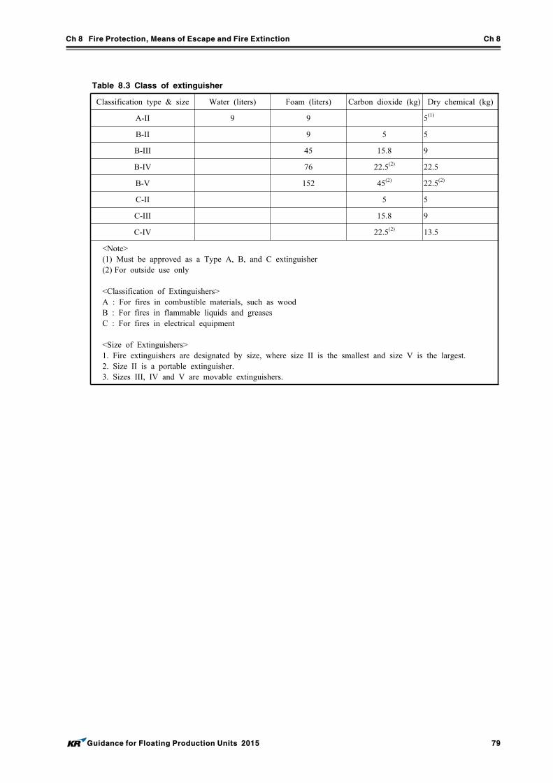
Ch 8 Fire Protection, Means of Escape and Fire Extinction Ch 8
Guidance for Floating Production Units 2015 79
Table 8.3 Class of extinguisher
Classification type & size Water (liters) Foam (liters) Carbon dioxide (kg) Dry chemical (kg)
A-II 9 9 5(1)
B-II 9 5 5
B-III 45 15.8 9
B-IV 76 22.5(2) 22.5
B-V 152 45(2) 22.5(2)
C-II 5 5
C-III 15.8 9
C-IV 22.5(2) 13.5
<Note>(1) Must be approved as a Type A, B, and C extinguisher (2) For outside use only
<Classification of Extinguishers>A : For fires in combustible materials, such as wood B : For fires in flammable liquids and greases C : For fires in electrical equipment
<Size of Extinguishers>1. Fire extinguishers are designated by size, where size II is the smallest and size V is the largest. 2. Size II is a portable extinguisher. 3. Sizes III, IV and V are movable extinguishers.
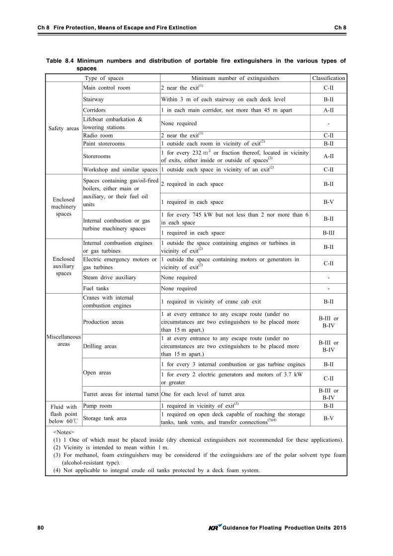
Ch 8 Fire Protection, Means of Escape and Fire Extinction Ch 8
80 Guidance for Floating Production Units 2015
Table 8.4 Minimum numbers and distribution of portable fire extinguishers in the various types of
spaces
Type of spaces Minimum number of extinguishers Classification
Safety areas
Main control room 2 near the exit(1) C-II
Stairway Within 3 m of each stairway on each deck level B-II
Corridors 1 in each main corridor, not more than 45 m apart A-II
Lifeboat embarkation & lowering stations
None required -
Radio room 2 near the exit(1) C-IIPaint storerooms 1 outside each room in vicinity of exit(2) B-II
Storerooms1 for every 232 m or fraction thereof, located in vicinity of exits, either inside or outside of spaces(2) A-II
Workshop and similar spaces 1 outside each space in vicinity of an exit(2) C-II
Enclosed machinery
spaces
Spaces containing gas/oil-fired boilers, either main or auxiliary, or their fuel oil units
2 required in each space B-II
1 required in each space B-V
Internal combustion or gas turbine machinery spaces
1 for every 745 kW but not less than 2 nor more than 6 in each space
B-II
1 required in each space B-III
Enclosed auxiliary spaces
Internal combustion engines or gas turbines
1 outside the space containing engines or turbines in vicinity of exit(2) B-II
Electric emergency motors or gas turbines
1 outside the space containing motors or generators in vicinity of exit(2) C-II
Steam drive auxiliary None required -
Fuel tanks None required -
Miscellaneous areas
Cranes with internal combustion engines
1 required in vicinity of crane cab exit B-II
Production areas1 at every entrance to any escape route (under no circumstances are two extinguishers to be placed more than 15 m apart.)
B-III or B-IV
Drilling areas1 at every entrance to any escape route (under no circumstances are two extinguishers to be placed more than 15 m apart.)
B-III or B-IV
Open areas
1 for every 3 internal combustion or gas turbine engines B-II
1 for every 2 electric generators and motors of 3.7 kW or greater
C-II
Turret areas for internal turret One for each level of turret area B-III or
B-IV
Fluid with flash point below 60℃
Pump room 1 required in vicinity of exit(3) B-II
Storage tank area1 required on open deck capable of reaching the storage tanks, tank vents, and transfer connections(3)(4) B-V
<Notes>(1) 1 One of which must be placed inside (dry chemical extinguishers not recommended for these applications).(2) Vicinity is intended to mean within 1 m. (3) For methanol, foam extinguishers may be considered if the extinguishers are of the polar solvent type foam
(alcohol-resistant type). (4) Not applicable to integral crude oil tanks protected by a deck foam system.
Ch 8 Fire Protection, Means of Escape and Fire Extinction Ch 8
Guidance for Floating Production Units 2015 81
303. Fire detection and alarm systems
1. Open or enclosed areas are to be provided with automatic fire detection such that all potential fire outbreak points are monitored. The automatic fire detection system will sound an alarm and initiate necessary shutdown functions for the facility. Guidelines for the selection and use of fire detectors are contained in API RP 14C, API RP 14FZ and API RP 14G.
2. A smoke detection and alarm system is to be provided for control rooms, switchgear rooms, and other areas where slow-developing fires might be expected.
3. A master fire and gas panel is to be located in the central control room or other normally manned non-classified area.
4. Means are to be provided for manually activating a general alarm system capable of producing a distinctive audible sound in all areas of the unit. Alarm-actuating devices are to be located at points of egress from accommodation areas, production areas, and machinery spaces. Power for the general alarm system is to comply with Ch 10.
304. Gas detection and alarm systems
1. In all enclosed and semi-enclosed areas that might accumulate combustible gases, gas sensors of an explosion proof type are to be installed and operated in accordance with API RP 14C and API RP 14FZ. Consideration is to be given to providing combustible gas sensors near points of a possible leak at process equipment and piping systems located in open areas. Sensors are also to be pro-vided at fresh air inlets to non-classified areas.
2. Where hydrogen sulfide gas may be present in the well fluid in excess of 20 ppm, hydrogen sul-fide gas detection systems are to be installed in accordance with API RP 55.
3. The low and high gas alarm set points are to be at 20% L.E.L. and 60% L.E.L. for combustible gases, and 10 ppm and 50 ppm for hydrogen sulfide. Process safety shutdown functions are to be initiated upon high gas detection.
305. Fireman’s Outfits
1. Fire-fighter's outfits are to comply with the Fire Safety Systems Code.
2. A minimum of two sets of fire-fighting outfits and equipment is to be provided and stowed in a suitable container.
3. The fireman’s outfits or sets of personal equipment are to be stored as to be easily accessible and ready for use, and where more than one fireman’s outfit or more than one set of personal equip-ment is carried, they are to be stored in widely separated positions.
4. One of the outfits should be readily accessible from the helicopter deck.
Ch 8 Fire Protection, Means of Escape and Fire Extinction Ch 8
82 Guidance for Floating Production Units 2015
Section 4 Means of Escape
401. Muster Stations
1. General
All units are to have a designated muster stations where personnel can gather prior to entering the lifeboats.
2. Materials
All materials that comprise the muster stations routes are to be of steel or equivalent material.
3. Muster stations
(1) The muster station is to be of sufficient area to accommodate the number of personnel to be gathered.
(2) The muster station is to be located in a safe location with respect to the processing equipment.(3) The muster station may be a meeting room inside the accommodations or may be part of the
lifeboat embarkation station.
402. Escape route
1. Materials
All materials that comprise the escape routes are to be of steel or equivalent material.
2. Escape route
(1) At least two means of escape are to be provided for all continuously manned areas, and areas that are used on a regular working basis.
(2) The two means of escape are to be through routes that minimize the possibility of having both routes blocked in an emergency situation.
(3) Escape routes are to have a minimum width of 700 mm. (4) Dead-end corridors exceeding 7 m in length are not permitted. (5) Dead-end corridors are defined as a pathway which (when used during an escape) has no exit.
3. Marking and lighting of escape routes
Escape route paths are to be properly identified and provided with adequate lighting.
4. Escape route plan
(1) An escape route plan is to be prominently displayed at various points in the unit. (2) Alternatively, this information may be included in the fire control plan.
403. Breathing Apparatus
1. A self-contained breathing apparatus of an approved type for escape purposes is to be provided for each person in working areas where hydrogen sulphide may be encountered.
2. The breathing apparatus for maintenance personnel is to have a minimum of 30 minutes air supply.
3. A designated safe area with proper supply of air is also to be provided and shown on the fire control plan.
404. Means of Embarkation
1. A unit is to have means of embarkation to allow personnel to leave the unit in an emergency.
2. The means of embarkation are to consist of at least two fixed ladders or stairways, widely sepa-rated, and extending from the main decks to the water line.
3. The ladders or stairways will preferably be located near lifeboat-launching stations.
4. Ladder construction is to be in accordance with the appropriate governmental authority, or other recognized standard.
Ch 9 Machinery Installations Ch 9
Guidance for Floating Production Units 2015 83
CHAPTER 9 MACHINERY INSTALLATIONS
Section 1 General
101. Application
1. The requirements of this Chapter do not apply to the machinery installations used solely for pro-duction and process operation.
2. In the case of items not specified in this Chapter, the requirements specified in Ch 5, Ch 7, Ch 8 and Ch 9 of Rules for the Classification of the Mobile Offshore Drilling Units and Pt 7, Ch 1 of Rules for the Classification of Steel Ships are to be applied.
102. General
1. Machinery installations are to be of a design and construction adequate for the service for which they are intended and are to be installed and protected so as to reduce to a minimum any danger to persons on board with due regard being paid to moving parts, hot surfaces and other hazards. Designs is to have regard to the purpose for which the equipment is intended, the working con-ditions to which it will be subjected and the environmental conditions on board. The temperature of piping systems and machinery which may be exposed to gas and crude oil is not to exceed 200 ℃.
2. Conditions of inclinations
All machinery, components and systems essential to the safe operation of a unit are to be designed to operate under the following static conditions of inclination :(1) when column-stabilized units are upright and inclined to an angle up to 15° in any direction :(2) when ship type units are upright and level trim and when inclined to an angle of list up to 15°
either way and simultaneously trimmed to an angle up to 5° by the bow or stern. The Society may permit or require deviations from these angles, in consideration of the type, size and service conditions of the unit.
Section 2 Piping Systems for Crude Oil Tanks
201. Inert gas systems for crude oil tank
1. On units equipped for storage of liquid hydrocarbons, a permanently installed inert gas system is to be provided for tank purging and inerting.
2. Inert gas systems are to be comply with Pt 8, Annex 8-5 of Rules for the Classification of Steel Ships.
202. Crude oil tanks venting system
1. Where pressure/vacuum relief valves are fitted on crude oil tanks, pressure relief lines are to be connected to the low-pressure flare header, or vented to a safe location.
2. The crude oil tanks venting system is to be designed and constructed in accordance with Pt 8, Ch 2, 104. 3 of Rules for the Classification of Steel Ships.
Section 3 Use of Produced Gas as Fuel
301. General
Boilers, gas turbines and internal combustion engine using produce gas as fuel are to comply with the requirements given in Pt 7, Ch 6, Sec 16 of Rules for the Classification of Steel Ships
Ch 9 Machinery Installations Ch 9
84 Guidance for Floating Production Units 2015
in addition to requirements given in this Chapter.
302. Ventilation systems
1. The ventilation of boiler and engine rooms is to be carried out at pressures which exceed atmos-pheric pressure. Main ventilation systems are to be independent of all other ventilation systems. The number of pressure fans for boiler and engine rooms are to be such that capacity is not reduced by more than 50%, if one fan is out of operation.
2. Ventilation systems are to ensure good air circulation in all spaces, and in particular, ensure that there is no possibility of the formation of gas pockets in any space.
303. Gas fuel supply systems
Gas processing systems including storage vessels, compressors, separators, filters, pressure control valves, etc., are to be located in hazardous areas and separated from boiler and engine rooms by gas-tight bulkheads.
304. Enclosed spaces above decks having boilers and engines
1. Enclosed spaces above decks having boilers and engines using produced gas as fuel, are to have ventilation systems providing at least 30 air changes per hour.
2. These spaces are to be fitted with gas detection systems to alarm at 20% L.E.L., and to activate automatic shutdown of the gas supply at 60% L.E.L.
3. The automatic shutdown valve is to be located outside the space. This valve is also to be activated upon loss of the required ventilation in the enclosed space, and upon detection of abnormal pres-sure in the gas supply line.
305. Produced gas containing hydrogen sulfide(H2S)
1. For produced gas containing hydrogen sulfide(H2S), provisions are to be made for gas sweetening, unless the equipment manufacturer has certified the suitability of the equipment for sour gas appli-cation, and the equipment is located in a freely ventilated open space.
2. To bring fuel gas containing H2S to the equipment located in an enclosed machinery space, the sour gas is to be sweetened. Additionally, the machinery space is to be equipped with H2S gas detectors. The detectors are to be set to alarm at 10 ppm and to activate the shutdown valve at 50 ppm.
Section 4 Boilers Using Crude Oil
401. General
Requirements given in this Chapter are to apply to boilers using crude oil with flash points not ex-ceeding 43℃ as fuel (hereinafter referred to as fuel oil).
402. Boilers
1. The whole surface of boilers is to be gas-tight and separated from engine rooms.
2. Means are to be provided for boilers to be automatically purged before firing.
3. Warning notices describing measures to be taken in cases where the gas detectors specified in 405. are activated is to be fitted in easily visible locations near boiler controls.
4. One pilot burner in addition to the one used for normal burning control is required.
Ch 9 Machinery Installations Ch 9
Guidance for Floating Production Units 2015 85
403. Fuel supply systems
1. Fuel oil is to be directly sucked into fuel injection pumps from crude oil tanks or exclusive fuel oil tanks. However, such fuel oil is to be subjected to suitable treatment. The exclusive fuel oil tanks are to be separated from non-hazardous areas by means of cofferdams with gas-tight bulkheads.
2. The auxiliary systems, including pumps, strainers, heaters and etc., is to be fitted in hazardous areas and separated from engine and boiler rooms by gas-tight bulkheads.
3. In cases where fuel oil is heated by steam or hot water, heating coil outlets are to lead to separate observation tanks. The observation tanks are to be closed tanks and installed in hazardous areas. The observation tank is to be fitted with a air pipes and opening end of the air pipe is led to the position specified in Pt 8, Ch 2, 104. 3 (4) (A) (c) of Rules for the Classification of Steel Ships and to be fitted with the flame screen specified in Pt 7, Ch 7, 1003. 2 (3) of Rules for the Classification of Steel Ships equivalent thereto.
4. The electric prime movers of pumps are to be fitted in machinery space or areas other than the hazardous areas specified in Ch 7. In cases where drive shafts pass through pump room bulkheads or deck plating, means of ensuring the permanence of the gastight seal specified in Pt 7, Ch 1, 1002. 1 (1) (B) of Rules for the Classification of Steel Ships are to be fitted.
5. Pumps are to be fitted with pressure relief bypasses from the delivery to suction sides.
6. Pumps are to be capable of being remotely stopped from the following positions:(1) Near boilers or machinery control rooms(2) Outside engine rooms
7. In cases where it is necessary to preheat fuel oil, automatic temperature control devices and high temperature alarm devices are to be fitted.
8. The crude oil piping is, as far as practicable, to be fitted with a slope rising towards the boiler so that the oil naturally returns towards the pump room in the case of leakage or failure in delivery pressure.
9. Fuel oil pipes in engine rooms and boiler rooms are to be fitted within metal ducts. Such ducts are to be gas-tight and tightly connected to the fore bulkheads separating pump rooms. These ducts are to be at an incline rising towards boilers so that oil naturally returns towards pump room in the case of leakage, etc.
10. Duct are to be fitted with gas-tight inspection doors in way of the pipe connections within such ducts, with automatic closing drain traps placed on the pump room side which are set in such a way as to discharge any fuel oil leakage into pump rooms.
11. Ducts are to be fitted with air pipes and opening end of the air pipe is led to the position speci-fied in Pt 8, Ch 2, 104. 3 (4) (A) (c) of Rules for the Classification of Steel Ships and to be fitted with the flame screen specified in Pt 7, Ch 7, 1003. 2 (3) of Rules for the Classification of Steel Ships equivalent thereto.
12. Ducts are to be permanently connected to inert gas systems or steam pipes in order to make pos-sible:(1) The injection of inert gas or steam in the duct in case of fire or leakage(2) The purging of the duct before carrying out work on the piping in case of leakage
13. Shutoff valves remotely controlled from positions near boiler fronts or machinery control rooms are to be provided on the on pump room side of fuel pipes passing through pump room bulkheads. Remote control valves are to be interlocked with hood exhaust fans to ensure that whenever fuel oil is circulating the fans are running.
14. Emergency shutdown valves are to be fitted on the fuel oil supply to each boiler manifold.
15. Boilers are to be fitted with suitable drip trays placed in such a way as to collect any possible oil leakage from burners, valves and connections. Such drip trays are to be fitted with removable flame arresting wire gauze and drain pipes discharging into drain tanks in pump rooms.
16. Drain tanks are to be fitted with air pipes and opening end of the air pipe is led to the position specified in Pt 8, Ch 2, 104. 3 (4) (A) (c) of Rules for the Classification of Steel Ships and
Ch 9 Machinery Installations Ch 9
86 Guidance for Floating Production Units 2015
to be fitted with the flame screen specified in Pt 7, Ch 7, 1003. 2 (3) of Rules for the Classification of Steel Ships equivalent thereto. Additionally, liquid level indicators and alarm systems are to be provided in order to detect leaks.
17. Drain pipes are to be fitted with arrangements to prevent the return of gas into boiler or engine rooms.
18. Burning systems are to be equipped with suitable mechanical interlocking devices so that running on normal fuel oil automatically excludes running on other fuel oils and vice versa.
404. Ventilation systems
1. Boilers are to be fitted with suitable hoods placed in such a way as to enclose as much of the burners, valves and fuel oil pipes as possible without blocking combustion air inlets.
2. Hoods are to be fitted with suitable doors placed in such a way as to enable the inspection of and access to fuel oil pipes and valves.
3. Hoods are to be fitted with ducts. Such ducts are led to the position specified in Pt 8, Ch 2, 104. 3 (4) (A) (c) of Rules for the Classification of Steel Ships and to be fitted with the flame screen specified in Pt 7, Ch 7, 1003. 2 (3) of Rules for the Classification of Steel Ships equivalent thereto.
4. At least two non-sparking mechanical ventilation systems are to be fitted so that the pressure inside hoods is less than that in boiler rooms. Ventilation systems are to be capable of automatic change-overs in the case of stoppages or failures.
5. The prime movers of the ventilation systems specified in Par 4 above are to be placed outside ducts and gastight bulkhead penetrations are to be arranged for shafts.
6. Boiler compartments are to be fitted with mechanical ventilation systems and are to be designed in such a way as to avoid the formation of gas pockets. Ventilation systems are to be separated from those intended for other spaces.
405. Gas detectors
1. The gas detectors specified in Pt 7, Ch 5, Sec 13 of Rules for the Classification of Steel Ships are to be fitted with intakes in the ducts specified in 403., in the ventilation hoods speci-fied in 404. and in all spaces where gas dispersion may not occur.
2. Gas concentration visual alarm devices are to be provided near boiler fronts and in machinery con-trol rooms. And gas concentration audible alarm devices are to be provided in machinery spaces and control rooms.
Ch 10 Electrical Equipment and Control Systems Ch 10
Guidance for Floating Production Units 2015 87
CHAPTER 10 ELECTRICAL EQUIPMENT AND CONTROL SYSTEMS
Section 1 Electrical Equipment
101. General
1. Application
(1) The requirements of this Section apply to the electrical equipment installed in the unit.(2) The electrical equipment other than that used solely for production operation is to comply with
relevant requirements in Pt 6, Ch 1 of Rules for the Classification of Steel Ships in addi-tion to the requirements of this Section.
(3) The electrical equipment used solely for production operation is applied only for the unit with Production notation specified in Ch 2.
2. Codes and standards
In the case of items not specified in this Chapter, API RP 14FZ or equivalent recognised standards such IEC.
3. Condition of inclinations
The emergency generator and its prime mover and any emergency accumulator battery are to be designed to function at full rated power when upright and when inclined up to the maximum angle of heel in the intact and damaged condition, as determined in accordance with Ch 4 of Rules for the Classification of Mobile Offshore Drilling Units. However, in no case need the equipment be designed to operate when inclined more than:(1) 25° in any direction on a column-stabilized; (3) 22.5° about the longitudinal axis and/or when inclined 10° about the transverse axis on a ship
type unit.
102. Design
1. Installation and protective inclosure
Electrical equipment and enclosures are to be provided with a degree of protection suitable to the environment or hazard in which they are located, in accordance with Pt 6, Ch 1 of Rules for the Classification of Steel Ships or API RP 14FZ.
2. Selection of materials
Materials of construction are to be selected that are suitable for their intended service and location.
3. Earthing of electrical equipment
(1) Fixed electrical equipment(A) All electrical equipment with metallic enclosures, whose arrangement and method of in-
stallation does not assure positive grounding to the metal hull or equivalent conducting body, is to be permanently grounded through a separate conductor, and protected against damage.
(B) Where separate grounding conductors are required, they are to be in accordance with API RP 14FZ.
(C) Systems designed to other recognized standards are to comply with such standards, but in no case are the separate grounding conductors to be of a cross-sectional area of less than indicated in Table 10.1.
(2) Lightning protection Equipment and structure are to be protected against lightning damage in accordance with NFPA
780 or other recognized standard.
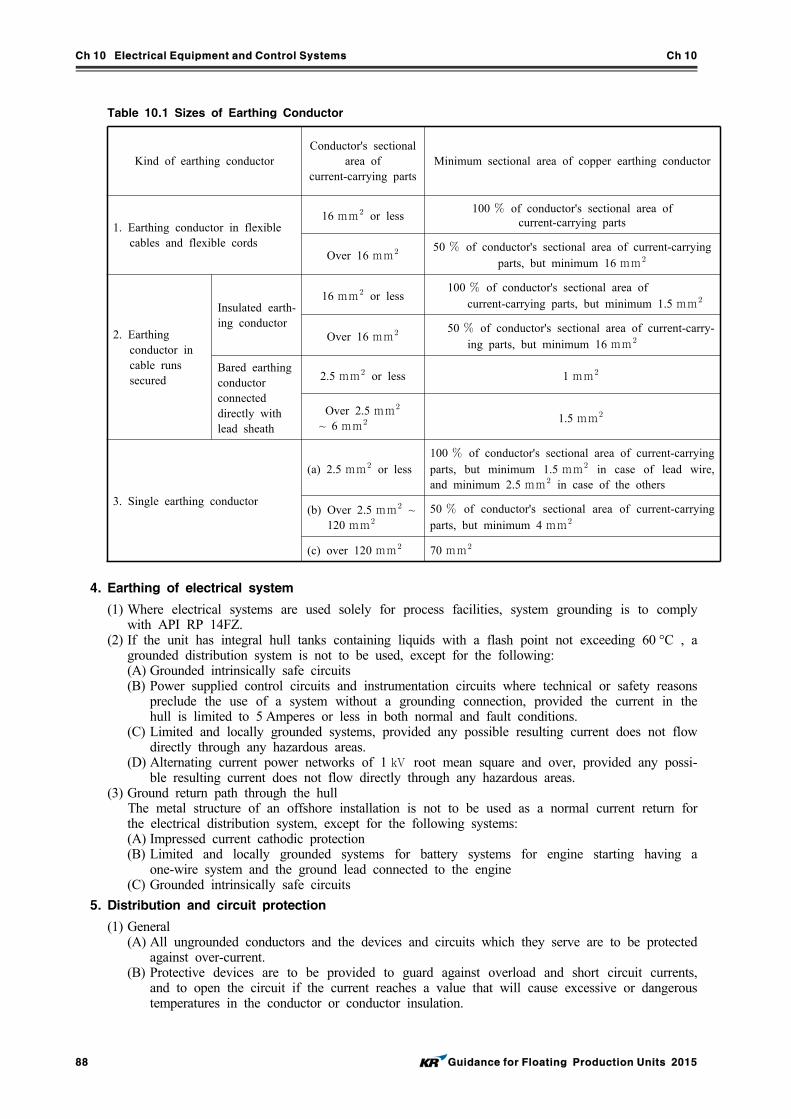
Ch 10 Electrical Equipment and Control Systems Ch 10
88 Guidance for Floating Production Units 2015
Table 10.1 Sizes of Earthing Conductor
Kind of earthing conductorConductor's sectional
area of current-carrying parts
Minimum sectional area of copper earthing conductor
1. Earthing conductor in flexible cables and flexible cords
16 mm or less100 of conductor's sectional area of
current-carrying parts
Over 16 mm 50 of conductor's sectional area of current-carrying parts, but minimum 16 mm
2. Earthing conductor in cable runs secured
Insulated earth-ing conductor
16 mm or less100 of conductor's sectional area of
current-carrying parts, but minimum 1.5 mm
Over 16 mm 50 of conductor's sectional area of current-carry-ing parts, but minimum 16 mm
Bared earthing conductor connected directly with lead sheath
2.5 mm or less 1 mm
Over 2.5 mm
~ 6 mm 1.5 mm
3. Single earthing conductor
(a) 2.5 mm or less100 of conductor's sectional area of current-carrying parts, but minimum 1.5 mm in case of lead wire, and minimum 2.5 mm in case of the others
(b) Over 2.5 mm ~ 120 mm
50 of conductor's sectional area of current-carrying parts, but minimum 4 mm
(c) over 120 mm 70 mm
4. Earthing of electrical system
(1) Where electrical systems are used solely for process facilities, system grounding is to comply with API RP 14FZ.
(2) If the unit has integral hull tanks containing liquids with a flash point not exceeding 60 °C , a grounded distribution system is not to be used, except for the following: (A) Grounded intrinsically safe circuits (B) Power supplied control circuits and instrumentation circuits where technical or safety reasons
preclude the use of a system without a grounding connection, provided the current in the hull is limited to 5 Amperes or less in both normal and fault conditions.
(C) Limited and locally grounded systems, provided any possible resulting current does not flow directly through any hazardous areas.
(D) Alternating current power networks of 1 kV root mean square and over, provided any possi-ble resulting current does not flow directly through any hazardous areas.
(3) Ground return path through the hull The metal structure of an offshore installation is not to be used as a normal current return for
the electrical distribution system, except for the following systems:(A) Impressed current cathodic protection(B) Limited and locally grounded systems for battery systems for engine starting having a
one-wire system and the ground lead connected to the engine(C) Grounded intrinsically safe circuits
5. Distribution and circuit protection
(1) General (A) All ungrounded conductors and the devices and circuits which they serve are to be protected
against over-current.(B) Protective devices are to be provided to guard against overload and short circuit currents,
and to open the circuit if the current reaches a value that will cause excessive or dangerous temperatures in the conductor or conductor insulation.
Ch 10 Electrical Equipment and Control Systems Ch 10
Guidance for Floating Production Units 2015 89
(2) Motor controllers Motor starting and control installations, including overload protection and short circuit protection,
are to be in accordance with API RP 14FZ.
103. Rotating machinery
1. General
Motors and generators are to be designed, manufactured and tested to NEMA Standard MG-1 or KS C IEC 60034 for performance, manufacture, protection, and construction.
2. Temperature rating
(1) Equipment is to be selected for the rated temperature higher than the specified ambient temperature. If equipment is intended to be used in a space where the equipment’s rated tem-perature is below the specified ambient temperature of the space, it is to be used at a derated load.
(2) The assumed ambient temperature of the space plus the machine’s actual temperature rise at its derated load is not to exceed the machine’s total rated temperature (rated temperature of the machine plus rated temperature rise).
3. Moisture condensation protection
(1) Generators and motors are to be provided with means, such as space heater, etc., to prevent ac-cumulation of moisture and condensation when they are idle for appreciable periods.
(2) The space heaters are to be capable of being electrically isolated.
4. Temperature detection
Generators larger than 500 kVA are to be provided with at least one embedded temperature detector per phase, at the hot end of the stationary winding, with temperature indication at a manned location.
104. Transformers
1. General
(1) Each power transformer is to be provided with a corrosion resistant nameplate indicating the name of the manufacturer and all pertinent electrical characteristics.
(2) They are to be constructed and tested to ANSI C57 or equivalent.(3) Transformers are to be protected in accordance with API RP 14FZ, Section 8.
2. Transformer supplying services other than production operation
In addition to the above, transformers supplying services other than oil or gas production are to be selected, installed, and protected in accordance with their environmental conditions and Pt 6, Ch 1, Sec 6 of Rules for the Classification of Steel Ships.
105. Switchgear
1. Application
Main and emergency switchboards, power and lighting distribution boards, motor control centers and motor controllers, and battery charging panels, are to be designed, constructed, and tested in accord-ance with the provisions of this Article.
2. Construction, assembly and components
(1) Enclosures (A) Enclosures and assemblies are to be constructed of steel or other suitable incombustible,
moisture-resistant materials, and reinforced as necessary to withstand the mechanical, elec-tro-magnetic and thermal stresses which may be encountered under both normal and short circuit fault conditions.
(B) Enclosures are to be of the closed type. (C) The degree of the protection is to be appropriate for the intended location according to 102. 1.
(D) All wearing parts are to be accessible for inspection and be readily renewable.
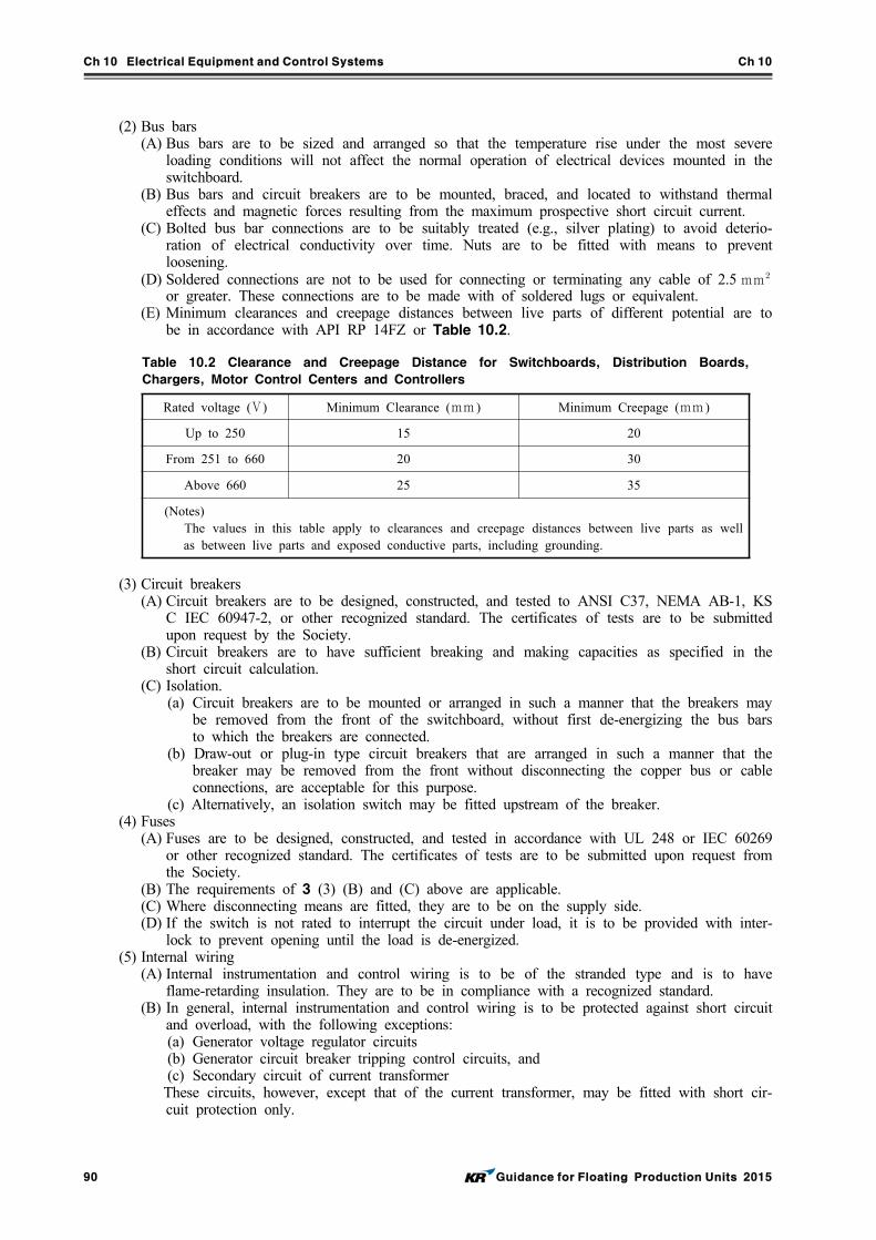
Ch 10 Electrical Equipment and Control Systems Ch 10
90 Guidance for Floating Production Units 2015
(2) Bus bars (A) Bus bars are to be sized and arranged so that the temperature rise under the most severe
loading conditions will not affect the normal operation of electrical devices mounted in the switchboard.
(B) Bus bars and circuit breakers are to be mounted, braced, and located to withstand thermal effects and magnetic forces resulting from the maximum prospective short circuit current.
(C) Bolted bus bar connections are to be suitably treated (e.g., silver plating) to avoid deterio-ration of electrical conductivity over time. Nuts are to be fitted with means to prevent loosening.
(D) Soldered connections are not to be used for connecting or terminating any cable of 2.5 mm or greater. These connections are to be made with of soldered lugs or equivalent.
(E) Minimum clearances and creepage distances between live parts of different potential are to be in accordance with API RP 14FZ or Table 10.2.
Table 10.2 Clearance and Creepage Distance for Switchboards, Distribution Boards,
Chargers, Motor Control Centers and Controllers
Rated voltage (V ) Minimum Clearance (mm ) Minimum Creepage (mm )
Up to 250 15 20
From 251 to 660 20 30
Above 660 25 35
(Notes) The values in this table apply to clearances and creepage distances between live parts as well
as between live parts and exposed conductive parts, including grounding.
(3) Circuit breakers (A) Circuit breakers are to be designed, constructed, and tested to ANSI C37, NEMA AB-1, KS
C IEC 60947-2, or other recognized standard. The certificates of tests are to be submitted upon request by the Society.
(B) Circuit breakers are to have sufficient breaking and making capacities as specified in the short circuit calculation.
(C) Isolation. (a) Circuit breakers are to be mounted or arranged in such a manner that the breakers may
be removed from the front of the switchboard, without first de-energizing the bus bars to which the breakers are connected.
(b) Draw-out or plug-in type circuit breakers that are arranged in such a manner that the breaker may be removed from the front without disconnecting the copper bus or cable connections, are acceptable for this purpose.
(c) Alternatively, an isolation switch may be fitted upstream of the breaker. (4) Fuses
(A) Fuses are to be designed, constructed, and tested in accordance with UL 248 or IEC 60269 or other recognized standard. The certificates of tests are to be submitted upon request from the Society.
(B) The requirements of 3 (3) (B) and (C) above are applicable. (C) Where disconnecting means are fitted, they are to be on the supply side. (D) If the switch is not rated to interrupt the circuit under load, it is to be provided with inter-
lock to prevent opening until the load is de-energized. (5) Internal wiring
(A) Internal instrumentation and control wiring is to be of the stranded type and is to have flame-retarding insulation. They are to be in compliance with a recognized standard.
(B) In general, internal instrumentation and control wiring is to be protected against short circuit and overload, with the following exceptions: (a) Generator voltage regulator circuits (b) Generator circuit breaker tripping control circuits, and (c) Secondary circuit of current transformer
These circuits, however, except that of the current transformer, may be fitted with short cir-cuit protection only.
Ch 10 Electrical Equipment and Control Systems Ch 10
Guidance for Floating Production Units 2015 91
(C) Terminals(a) Terminals or terminal rows for systems of different voltages are to be clearly separated
from each other, and the rated voltage is to be clearly marked. (b) Each terminal is to have a nameplate indicating the circuit designation.
(6) Circuit identification Identification plates for feeders and branch circuits are to be provided, and are to indicate the
circuit designation and the rating or settings of the fuse or circuit breaker of the circuit.
3. Switchboards
(1) In addition to the 105. 2, main and emergency switchboards are to comply with this Paragraph. (2) Bus bars Bus bars for switchboards supplied by generators are to comply with API RP 14FZ. (3) Power generation switchboards At minimum, the following equipment and instrumentation are to be provided for switchboards
associated with power generation: (A) Voltage regulators (B) Synchronizing controls (C) Synchronizing relay (D) Ground fault detection (E) Prime mover speed control (F) Ammeter with selector switch arranged to measure each phase (G) Voltmeter with a selector switch (H) Frequency meter (I) Watt meter(J) Space heater pilot lamp – where required (K) Stator winding temperature indicator (500 kVA and larger generators)
4. Motor controllers
(1) In addition to the 105. 2, motor controllers are to comply with this Paragraph. (2) Overload and under-voltage Protection Overload protection and low-voltage protection, if provided in the motor controllers, are to be in
accordance with API RP 14FZ, or other recognized standard. (3) Disconnecting Means
(A) A circuit-disconnecting device is to be provided for each motor branch circuit so that the motor and the controller may be isolated from the power supply for maintenance purposes.
(B) The circuit-disconnecting device is to be operable externally.
5. Battery charging panels
(1) In addition to 105. 2, battery chargers are to comply with this Paragraph. (2) Battery charger Except when a different charging rate is necessary and is specified for a particular application,
the charging facilities are to be such that the completely discharged battery can be recharged to 80% capacity in not more than 10 hours.
(3) Reversal of charging current An acceptable means is to be installed, such as reverse current protection, to prevent the battery
charger component failure from discharging the battery. (4) The following Instrumentations are to be provided
(A) Disconnect switch for power supply to the charge (B) Indicator light connected to the downstream side of the disconnect switch in (A) (C) Means for adjusting the voltage for charging (D) Voltmeter to indicate the charging voltage(E) Ammeter to indicate the charging current
6. Switchgear supplying services other than production system
Main and emergency switchboards, power and lighting distribution boards, motor control centers and motor controllers, and battery charging panels that are used to supply services other than production systems, are to comply with Pt 6, Ch 1 of Rules for the Classification of Steel Ships. in ad-dition to this Article.
Ch 10 Electrical Equipment and Control Systems Ch 10
92 Guidance for Floating Production Units 2015
106. Wire and cable construction
1. General
All wires, cables, conduit fittings and wiring devices are to be constructed in accordance with IEEE, ICEA, IEC, or other recognized standards.
2. Conductor type
Conductors are to be of copper, and stranded in all sizes, and are to be in accordance with API RP 14FZ or other recognized standards, but in no case are they to be less than the following in cross sectional size:
(1) 1.5 mm for motor feeder and branch circuit cables(2) 1.0 mm for power lighting and control cables (3) 0.5 mm for essential or emergency signaling and communications cables, except for those as-
sembled by the equipment manufacturer, and (4) 0.375 mm for telephone cables for non-essential communications services, except for those as-
sembled by the equipment manufacturer.
3. Insulation (1) Conductor insulation is to be rated suitable for a minimum operating temperature of 75°C in
wet environments.(2) In addition, insulation rating is to be at least 10°C higher than the maximum ambient temper-
ature that the conductor can encounter at its service location.
4. Cable flame retardancy
(1) All electric cables are to be at least of a flame-retardant type complying with the following: (A) Cables constructed in accordance with IEEE, ICEA, IEC, or other recognized standards, are
to comply with the flammability criteria of IEEE Std. 45 or KS C IEC 60332-3-22.(B) Cables constructed to IEEE Std. 45 are to comply with the flammability criteria of that
standard. (C) Cables constructed to KS C IEC 60092 series are to comply with the flammability criteria
of IEC Publication 60332-3-22. (2) Consideration will be given to special types of cables, such as radio frequency cables, which do
not comply with the above requirements.
5. Fire resistant property
When electric cables are required to be fire-resistant, they are to comply with the requirements of KS C IEC 60331 series.
107. Cable support and installation
1. Mechanical protection
For cables which are not equipped with metal armor or metal sheathing, installation in rigid con-duit or similar structural protection is to be utilized if such cable is employed near walkways, at deck level, near hoist or crane laydown or work areas, or where equipment maintenance work must be accomplished in a constrained area.
2. Splicing
(1) General (A) Electrical cables are to be installed in continuous lengths between terminations. However,
approved splices will be permitted for cables of exceptional length, to facilitate their installation.
(B) The location and particulars of the splices are to be submitted to the Society for review. (2) Construction
(A) Cable splice is to be made of fire-resistant replacement insulation equivalent in electrical and thermal properties to the original insulation.
(B) The replacement jacket is to be at least equivalent to the original impervious sheath, and is to assure a watertight splice.
(C) Splices are to be made using the splice kit, which is to contain the following:
Ch 10 Electrical Equipment and Control Systems Ch 10
Guidance for Floating Production Units 2015 93
(a) Connector of correct size and number (b) Replacement insulation (c) Replacement jacket (d) Instructions for use
(D) All cable splices are to be type approved before use.
108. Power source requirements
1. General
(1) The governmental regulations may require reserve main power or an emergency power source in excess of these requirements.
(2) Where the main power source is used to supply services other than production systems, the main power source is to comply with Pt 6, Ch 1 of Rules for the Classification of Steel Ships.
(3) Where the Flag Administration permits, the minimum number of required main power sources may be reduced to one source.
2. Unmanned facilities
(1) The main power source is to be sufficient to maintain the maximum intended operational loads of the unit, without need to use the emergency source of power.
(2) An emergency power source, independent of the unit’s main power, is to be sufficient to supply services for navigational aids as required by the cognizant Coastal Authority, but not for less than four days.
3. Manned facilities
(1) The main power source is to be sufficient to maintain the maximum intended operational load of the unit.
(2) Emergency power (A) An emergency source of power for systems vital to safety, fire fighting, and protection of
personnel, is to be provided.(B) Where an emergency power supply has been provided for classification/flag state purposes,
this source may also be used to provide emergency loads in production areas, provided the emergency source of power is adequately sized to supply all of the connected loads.
(C) Fire pump (a) If both fire pumps required by Ch 8, 302. 1 of these Rules are electric motor driven,
one of these pumps is to be powered by the emergency source of power.(b) The emergency source of power is to have sufficient fuel for at least 18 hours of fire
pump operation. (D) Other loads The emergency source of electrical power is to be capable of supplying simultaneously at
least the following services for the periods specified hereinafter: (a) Fire detection : 18 hours(b) Gas detection : 18 hours(c) Communication : 18 hours(d) ESD system (if electric) : 18 hours(e) Paging and alarm system : 18 hours (f) Emergency lighting from all spaces to all alternative egress points : 18 hours(g) Electric blowout preventer control system (h) Navigational aids: As required by the applicable Coastal Authority, but not less than 4
days
109. Emergency source of power
1. An emergency source of power as required by 108. may be supplied by an emergency generator or batteries, in accordance with API RP 14FZ.
2. Installations supplying services other than production systems are to be in accordance with Pt 6, Ch 1 of Rules for the Classification of Steel Ships.
Ch 10 Electrical Equipment and Control Systems Ch 10
94 Guidance for Floating Production Units 2015
110. Battery systems
1. Battery installations are to comply with API RP 14FZ.
2. Ventilation of battery rooms is to be separate from all other ventilation. Arrangements of equivalent safety will be given special consideration.
111. Short circuit current calculations and coordination study
1. The protection and coordination of power systems are to be in accordance with Pt 6, Ch 1 of Rules for the Classification of Steel Ships, Ch 6 of Rules for the Classification of the Mobile Offshore Drilling Units, IEC, IEEE 242, or other recognized standards.
2. The maximum calculated short circuit current available at the main bus bars and at each point in the distribution system, is to be used to determine the adequacy of the short circuit capacities of the protective devices and bus bar bracing.
3. The power system coordination study is to show that the protective devices and their settings are properly selected to minimize damage to switchgear, transformers, generators, motors, conductors, conductor shielding and other equipment, as well as undesirable shutdowns.
112. Protection from Ignition by Static Charges
1. Any ignition hazard due to a difference in electrical potential to ground is to be effectively controlled. This may require the use of conductive belts, grounding of combustible fluid loading or discharge equipment and hose, and the grounding of helicopters prior to refueling.
2. All precautions against ignition due to static electric discharge are to be in accordance with NFPA 77, or other recognized standards.
Section 2 Control Systems
201. General
1. Application
(1) Requirements in this Section apply to the instrumentation and control systems for offshore facilities.
(2) The design of these systems is to comply with API RP I4C or other recognized standards in addition to requirements in this Section.
2. General
(1) The control and instrumentation systems are to provide an effective means for monitoring and controlling pressures, temperatures, flow rates, liquid levels and other process variables for the safe and continuous operation of the facilities.
(2) Where control over the electrical power generation and distribution is required for the operation of the facilities then the control system should also be arranged to cover this.
(3) Control and instrumentation systems for process, process support, utility and electrical systems are to be suitable for the intended application.
(4) All control and safety shutdown, systems are to be designed for safe operation of the equipment during start-up, shutdown and normal operational conditions.
202. Components
1. All control system components are to be designed for use in a marine environment, resistant to corrosion, and capable of operating under all anticipated environmental conditions.
2. Each component is to be designed and tested for the extremes of pressure and temperature that it can encounter in service.
Ch 10 Electrical Equipment and Control Systems Ch 10
Guidance for Floating Production Units 2015 95
3. Where safety related functions are performed by computer based equipment then the equipment is to be in accordance with the requirements of Pt 6, Ch 2, 201. 7 of Rules for the Classification of Steel Ships.
4. Loss of control power to any device is not to cause the system to go into an unsafe condition. Cause and effect matrices are to demonstrate loss of control power effects.
203. Instruments
1. Temperature gauge
All temperature-sensing elements or devices are to be installed in separable socket type thermo-wells, so that they can be removed without danger of pressure or fluid release.
2. Pressure gauge
(1) Pressure switches supplied as safety devices are to be equipped with test connections to enable application of an external pressure source without disturbing the switch installation.
(2) Pressure gauges and sensors are to be provided with an isolation valve to permit the safe re-moval of the gauge without the need to reduce the pressure in the system.
(3) The open or closed position of the valve is to be readily identifiable from the position of the handle or stem.
3. Level gauge
(1) Liquid or interface level gauges are to be installed to cover the operating range and set points of level controllers or level switches.
(2) Direct viewing level gauges in processing or combustible fluid service are to be of the heavy-duty flat glass type and are to be equipped with self-closing valves at their ends.
204. Alarm systems
1. General
(1) Alarm systems are to be of the self-monitoring type and designed so that a fault in the alarm system is self-revealing or will cause it to fail to the alarmed condition.
(2) Alarms are not to react to normal transient conditions or false signals. (3) Alarm systems are to be independent of control and safety systems, except that common sensors
will be acceptable for non-shutdown related systems.
2. Visual and audible alarms
(1) Alarms are to be both audible and visual, and are to be provided at the control stations.(2) Alarms are to be such that each abnormal condition of the machinery and equipment is readily
distinguishable and so arranged that acknowledgement is clearly noticeable.(3) Visual alarms are to be displayed in a distinguishable manner such that alarms for similar proc-
ess components or systems are grouped together, and the colors representing a particular func-tion or condition remain uniform.
(4) Visual alarms are to flash when first activated. (5) Audible alarms associated with the process systems are to be of distinctive tone from other
alarms such as fire alarm, general alarm, gas detection, etc., and they are to be of sufficient loudness to attract the attention of personnel on duty.
(6) For spaces of unusual high noise levels, a beacon light or similar device, installed in a con-spicuous place is to supplement any of the audible alarms in such spaces; however, red light beacons are only to be used for fire alarms.
(7) A fault in the visual alarm circuits is not to affect the operation of the audible alarm circuits.
3. Acknowledgement of alarms
(1) Alarms are to be acknowledged by manually changing the flashing display of the incoming alarm to a steady display and by silencing the audible signal; the steady state light display is to remain activated until the fault condition is rectified.
(2) Alarming of other faults that may occur during the acknowledgement process is not to be sup-pressed by such action of above (1).
(3) Where a centralized control and monitoring station is provided, the silencing of the audible
Ch 10 Electrical Equipment and Control Systems Ch 10
96 Guidance for Floating Production Units 2015
alarm from an associated remote control station is not to lead automatically to the silencing of the original alarm at the centralized control and monitoring station.
4. Disconnection and resumption of alarm functions
Alarm circuits may be temporarily disabled for maintenance purposes or during initial plant start-up, provided such action is clearly indicated at the associated station in control and, where such station is provided, at the centralized control and monitoring station. However, such alarm is to be auto-matically re-activated after a preset time period.
5. Summary alarms
When individual alarms are displayed and alarmed at a centralized control and monitoring station, the visual alarms may be displayed and alarmed at other associated remote control stations as sum-mary alarms.
6. Built-in testing
Alarm systems are to be provided with effective means for testing all audible and visual alarms and indicating lamps without disrupting the normal machinery or system operation. Such means are to be fitted in the associated remote stations.
7. Adjustable set-points
Where means are provided to field adjustable set-points, either locally or remotely, positive in-dication of the value of the set-point is to be clearly identified at the control location.
205. Control and monitoring
1. Loss of control signal from a field sensing device is to initiate an alarm or cause a shutdown.
2. Display of parameters
(1) Operating parameter displays are to be clear, concise, consistent and grouped logically. (2) Operating parameter displays are to be included in control stations.
3. Logic circuit features
(1) When logic circuits are used for sequential start-up or for operating individual process compo-nents, indicators are to be provided at the control console to show the successful completion of the sequence of operations by the logic-circuit and start-up and operation of the process component.
(2) If some particular step is not carried out during the sequence, the sequence is to stop at this point, and such condition is to be alarmed at the control console or, where provided, at the centralized control and monitoring station.
(3) Feedback devices are to be employed in order to sense steps carried out during the start-up sequence. Sequence operation is to stop upon lack of feedback signal.
(4) Where valves are employed in any start-up sequence, valve condition is to be sensed as valve stem position and not as a function of control or power signal to the valve.
4. Overrides
(1) No condition of operation within normal ranges is to require the override of a required pro-tective device or function.
(2) Where shutdown functions are bypassed during special operational modes described below, sens-ing devices are to be arranged to continue to indicate the condition of each process variable.
(3) In addition, an indicator for each function is to alert the operator that the shutdown function is being “by-passed”.
(4) Provisions to override shutdown functions are to include the following: (A) To periodically test or calibrate field sensing device. (B) To take the vessel or other process component out of service. (C) To allow process conditions to stabilize, automatic bypass of shutdown functions on start-up
may be installed, provided the process variable condition is indicated, and an automated de-vice is fitted which will return the shutdown function to operation once the normal process condition has been attained. The use of timers in association with this required automatic function will be considered.
Ch 10 Electrical Equipment and Control Systems Ch 10
Guidance for Floating Production Units 2015 97
206. Safety systems
1. General
(1) Safety systems are to be of the fail-safe type and are to respond automatically to fault con-ditions that may endanger the plant or safety of the crew.
(2) Unless otherwise required in this Section or specially approved, this automatic action is to cause the plant to take the least drastic action first, as appropriate, by reducing its normal operating output or switching to a stand-by process component, and last, by stopping it.
(3) Actuation is to result in audible and visual alarm.
2. Constitution of systems
Safety systems are to be completely independent of the control and alarm systems so that a failure in one of these systems will not prevent the safety system from operating.
3. Function of safety systems
(1) Each safety action is to be alarmed at the associated remote station. (2) Where a centralized control and monitoring station is fitted, individual alarms are to be provided
at that station; in which case, a summary alarm for the specific safety system will be accept-able at other associated remote stations.
(3) When both an alarm and a safety action are required for a specific failure condition, the operat-ing points are to be arranged such that alarm is activated earlier.
(4) Process components that are stopped as a result of a safety action are to be manually reset be-fore their operation is resumed.
4. Override of safety provisions
(1) Any overrides of safety provisions are to be so arranged that they cannot go unnoticed, and their activation and condition are to be alarmed and indicated at the associated remote station.
(2) The override is to be arranged to preclude inadvertent operation and is not to deactivate alarms associated with safety provisions.
(3) The override mechanism to disconnect safety provisions is to be fitted at the associated remote station, except that where a centralized control and monitoring station is fitted, the override mechanism may be fitted at the centralized station instead.
207. Emergency control station
At least two emergency control stations are to be provided. One of the stations is to be located in a normally manned space such as the process control room, or near the drilling console if the unit is fitted with drilling systems. The other is to be at a suitable location outside of the hazardous area. The emergency control stations are to be provided with the following: (1) Manually operated switches for actuating the general alarm system (2) An efficient means of communication with locations vital to the safety of the installation (3) Manual activation of a emergency shutdown system (4) Means for shutdown, either selectively or simultaneously, of the following equipment, except for
electrical equipment listed in 207.11 (A) ventilating systems, except for prime movers(B) main generator prime movers(C) emergency generator prime movers
208. Emergency shutdown
1. An emergency shutdown (ESD) system with manual stations is to be provided to shut down the flow of hydrocarbon from all wells and pipelines, and to terminate all production and injection ac-tivities of the facility.
2. Shutdown is to take place within 45 seconds or less as may be considered necessary for the safety of the plant after activation of the ESD system at a manual ESD station, or after detection of a trouble condition by an automatic shutdown device.
3. The emergency shutdown system is to be automatically activated by: (1) The detection of an abnormal operating condition by flowline pressure sensors and sensors on
any downstream component through which the pipeline fluids flow;
Ch 10 Electrical Equipment and Control Systems Ch 10
98 Guidance for Floating Production Units 2015
(2) The detection of fire in the wellhead and process areas;(3) The detection of combustible gas at a 60% level of the lower explosive limit (LEL) (4) The detection of hydrogen sulfide (H2S) gas at a level of 50 ppm.
4. Station for activation of the ESD system for complete platform shutdown should be located as fol-lows:(1) Helicopter decks(2) Exit stairway landings at each deck level(3) Boat landings(4) At the center or each end of a bridge connecting two units(5) Emergency evacuation stations(6) Near the main exits of living quarters(7) Emergency control station(8) Process control station(9) Main exit of production area
5. Emergency shutdown stations are to be identified by shutdown function, and shutdown position is to be clearly indicated.
6. Emergency stopping devices are to function independently and be able to operate after the loss of main power.
7. Electric circuits essential to ESD that rely on the continued operation of the cable for correct oper-ation of the system are to be of the fire resisting type.
8. All electrical circuits used in the manual ESD system are to be dedicated to this purpose and hard wired.
9. In cases where emergency stopping devices are put into action and the operation of production sys-tem components are stopped, such components are not to automatically restart before manual reset is made.
10.Emergency shutdown valves for flowlines and pipelines are to be located as far away from the unit as practical.
11.The following services are to be operable after total shutdown of a unit:(1) Emergency lighting required for evacuation from service/accommodation spaces and machinery
spaces to embarkation stations. This includes lighting at all control stations, stowage positions for firemen’s outfits, helicopter landing deck, alleyways, stairways and exits, embarkation station deck, launching appliances, and the area of water where they are to be launched, etc. The light-ing is to be provided for thirty minutes.
(2) General alarm (3) Blowout preventer control system if fitted on the installations (4) Public address system (5) Distress and safety radio communications All equipment in exterior locations that is capable of operation after activation of the prime mov-er/ventilation shutdown system, is to be suitable for installation in Zone 2 locations.
209. Computer-based systems
1. General
(1) Computer-based systems are to be designed so that failure of any of the system’s process com-ponents will not cause unsafe operation of the system.
(2) Hardware and software serving vital and non-vital systems are to be arranged to give priority to vital systems.
2. Independence
(1) Control, alarm and safety shutdown system functions are to be arranged such that a single fail-ure or malfunction of the electronic computer equipment will not affect more than one of these system functions.
(2) This is to be achieved by dedicated equipment for each of these functions within a single sys-tem, or by the provision of back-up equipment, or by other suitable means considered equal or more effective.
Ch 10 Electrical Equipment and Control Systems Ch 10
Guidance for Floating Production Units 2015 99
3. Failure Mode and Effect Analysis (FMEA)/Failure Mode, Effect and Criticality Analysis (FMECA)
Where computer-based systems include safety functions (i.e., safety functions are not backed-up by hard-wired safety systems) an FMEA or FMECA is to be performed and submitted to the Society for review.
4. Visual display of alarms
(1) Incoming Signals (A) In addition to the requirements contained in 204., alarms are to be presented in an identifi-
able manner when displayed by way of a computer monitor (video display unit), and are to appear in the sequence the incoming signals are received.
(B) Alarming of incoming fault signals are to automatically appear on the screen to alert the on-duty personnel, regardless of whether the computer and monitor are in a mode other than the monitoring mode.
(2) Unrectified Alarms Alarms associated with faults which have not been rectified may be displayed in a summarized
fashion until all the faults have been dealt with. (3) Computer Monitor
(A) Displays on the computer monitor are to be clearly visible under ambient lighting conditions.
(B) Data displayed on computer monitors are to be readable by the operator from normal oper-ating position.
5. Memory capacity and response time
(1) Computer system’s memory is to be of sufficient capacity to handle the operation of all com-puter programs as configured in the computer system.
(2) The time response for processing and transmitting data is to be such that an undesirable chain of events may not arise as a result of unacceptable data delay or response time during the computer system's worst data overload operating condition.
6. Data loss and corruption
To preclude the possible loss or corruption of data as a result of power disruption, programs and data considered to be essential to the operation of a specific system are to be stored in non-volatile memory, or in volatile memory with a secure un-interruptible power supply (UPS).
7. Local Area Network (LAN)
For safety systems where an automatic or remote control and monitoring system for specific proc-ess components is arranged to operate in a local area network (LAN), the following is to be com-plied with:(1) The network topology is to be configured so that in the case of a failure between nodes, or at
a node, the system on the network remains operational. (2) In case of failure of the network controller, the network is to be arranged to automatically
switch to a standby controller. A network controller failure is to be alarmed at the associated remote control station.
(3) Safeguards are to be provided to prevent unacceptable data transmission delays (overloading of network). An alarm is to be activated at the associated remote control stations prior to a critical network data overload condition.
(4) The communication data highway is to be provided in duplicate and is to be arranged so that upon failure of the on-line highway, the standby data highway is automatically connected to the system. The standby data highway is not to be used to reduce traffic in the on-line highway.
8. Start-up after power failure
The system's software and hardware is to be designed so that upon restoration of power supply af-ter power failure, automatic or remote control and monitoring capabilities can immediately be avail-able after the pre-established computer control access procedure has been completed.
9. Parameters and program changes
Alteration of parameters that may affect the system's performance is to be limited to authorized personnel by means of keyswitch, keycard, password, or other approved methods.
Ch 10 Electrical Equipment and Control Systems Ch 10
100 Guidance for Floating Production Units 2015
10. Multiple points of control
Systems with multiple control stations are to be provided with clear indication at each location to identify the station in control, and are to be provided with procedures to ensure proper transfer of control.
Ch 11 Production and Process Systems Ch 11
Guidance for Floating Production Units 2015 101
CHAPTER 11 PRODUCTION AND PROCESS SYSTEMS
Section 1 General
101. Application
1. The requirements in this Chapter apply to production and process system installed in the unit with Production notation specified in Ch 2. For the production and process system installed in the unit without Production notation, safety related requirements of this Chapter including facility layout, safety system, process shutdown systems apply.
2. The requirements in this Chapter apply to equipment and systems for handling and processing pro-duced fluids from completed wells. However, systems supporting process system other than being directly engaged in processing produced fluids apply to Sec 4.
3. The requirements in this Chapter apply to facilities which are only installed on the unit and the boundary between production systems and other onboard systems are as the following:(1) from the first inlet flange of the well fluid flow line above the water level inboard for import
systems(2) to the flange connected with the inlet flange of the storage tank.
4. The requirements in this Chapter do not apply to production equipment which is installed in subsea such as a well head, a christmas tree and etc.
5. The requirements not specified in this Guidance are to be in accordance with relevant requirements in Ch 8, Ch 9, Ch 10.
6. They are also to be complied with National Regulations of the coastal state in which the unit is located during operation. Where statutory requirements of the National Authority are stricter than re-quirements of this Chapter, they are to be in accordance with statutory requirements of the National Authority.
7. The overboard discharge from the production treatment plan onboard is not subject to MARPOL Annex I but subject to the national and/or regional regulations.
102. General
1. Hydrocarbon processing systems and associated equipment are to be designed to minimize the risk of hazards to personnel and property caused by potential threats to safety, with considering the fol-lowings:(1) Prevent an abnormal condition from causing an upset condition(2) Prevent an upset condition from causing a release of hydrocarbons(3) Safely collect and dispose of hydrocarbon gasses and vapors released (4) Prevent formation of explosive mixtures (5) Prevent ignition of flammable liquids or gases and vapors released (6) Limit exposure of personnel to fire hazards
2. Structure that supports production facilities or forms an integral part of the equipment is to be de-signed to a recognized standard. Plans and calculations are to be submitted for the Society review. Process liquid weights and dynamic loads due to installation motions and other loads, such as wind imposed loads, are to be considered.
103. Codes and standards
1. The requirements not specified in this Chapter are to be in accordance with recognized national or international standards.
2. The following standards may be adequately referred as recognized national or international standards.
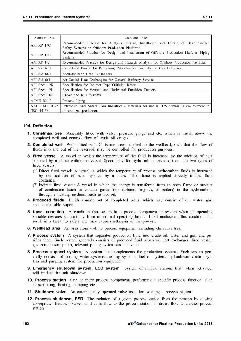
Ch 11 Production and Process Systems Ch 11
102 Guidance for Floating Production Units 2015
Standard No. Standard Title
API RP 14CRecommended Practice for Analysis, Design, Installation and Testing of Basic Surface Safety Systems on Offshore Production Platforms
API RP 14ERecommended Practice for Design and Installation of Offshore Production Platform Piping Systems
API RP 14J Recommended Practice for Design and Hazards Analysis for Offshore Production Facilities
API Std 610 Centrifugal Pumps for Petroleum, Petrochemical and Natural Gas Industries
API Std 660 Shell-and-tube Heat Exchangers
API Std 661 Air-Cooled Heat Exchangers for General Refinery Service
API Spec 12K Specification for Indirect Type Oilfield HeatersAPI Spec 12L Specification for Vertical and Horizontal Emulsion Treaters
API Spec 16C Choke and Kill Systems
ASME B31.3 Process Piping
NACE MR 0175 /ISO 15156
Petroleum And Natural Gas Industries - Materials for use in H2S containing environment in oil and gas production
104. Definition
1. Christmas tree Assembly fitted with valve, pressure gauge and etc. which is install above the completed well and controls flow of crude oil or gas.
2. Completed well Wells fitted with Christmas trees attached to the wellhead, such that the flow of fluids into and out of the reservoir may be controlled for production purposes.
3. Fired vessel A vessel in which the temperature of the fluid is increased by the addition of heat supplied by a flame within the vessel. Specifically for hydrocarbon services, there are two types of fired vessels: (1) Direct fired vessel: A vessel in which the temperature of process hydrocarbon fluids is increased
by the addition of heat supplied by a flame. The flame is applied directly to the fluid container.
(2) Indirect fired vessel: A vessel in which the energy is transferred from an open flame or product of combustion (such as exhaust gases from turbines, engines, or boilers) to the hydrocarbon, through a heating medium, such as hot oil.
4. Produced fluids Fluids coming out of completed wells, which may consist of oil, water, gas, and condensable vapor.
5. Upset condition A condition that occurs in a process component or system when an operating variable deviates substantially from its normal operating limits. If left unchecked, this condition can result in a threat to safety and may cause shutting-in of the process.
6. Wellhead area An area from well to process equipment including christmas tree.
7. Process system A system that separates production fluid into crude oil, water and gas, and pu-rifies them. Such system generally consists of produced fluid separator, heat exchanger, fired vessel, gas compressor, pump, relevant piping system and relevant.
8. Process support system A system that complements the production systems. Such system gen-erally consists of cooling water systems, heating systems, fuel oil system, hydraulic/air control sys-tem and purging system for production equipment.
9. Emergency shutdown system, ESD system System of manual stations that, when activated, will initiate the unit shutdown.
10. Process station One or more process components performing a specific process function, such as separating, heating, pumping etc.
11. Shutdown valve An automatically operated valve used for isolating a process station
12. Process shutdown, PSD The isolation of a given process station from the process by closing appropriate shutdown valves to shut in flow to the process station or divert flow to another process station.
Ch 11 Production and Process Systems Ch 11
Guidance for Floating Production Units 2015 103
13. Shut-in condition A condition resulting from the shutting-in of the facility which is caused by the occurrence of one or more undesirable events.
14. Upsteam process Process that draws up and transfer produced fluid to process equipment on the unit. Such process are generally from wellhead to inlet of the first process equipment on the unit.
15. Downstream process Process that purifies produced fluid by separating them into crude oil, water and gas on the unit.
16. Pipeline Piping that directs fluids between platforms or between a platform and a shore facility.
17. Flowline Piping that directs well stream from the well head to the frist downstream process component.
18. Production deck A deck that production facilities are installed on.
105. Design conditions
The production and process systems are to be designed to account for all applicable environmental, operational, and test loads, or combination thereof. These include the following:
1. Environmental Conditions(1) Earthquake (2) Wind Ice (3) Ice (4) Temperature (5) Current, waves (6) 1, 10, 50, 100 year storm event, as applicable
2. Operational (1) Static pressure (2) Vibration (3) Transient pressure excursion (4) Acceleration loads due to movement of installation (5) Temperature excursion (6) Fluid static head and properties (7) Tension (8) Bending
3. Transportation
4. Installation
5. Commissioning
6. Test loads
106. Classification survey during construction
1. Plans and documents to be submitted
(1) The following plans and documents are to be submitted for the approval of the Society at clas-sification survey during construction before the work is commenced.(A) General arrangement of production and process systems(B) Hazardous area classification plans and ventilation arrangement(C) Piping & instruments diagrams(D) Pressure relief and depressurization vent systems arrangement(E) Flare/gas release systems arrangements(F) Spill containment, closed and open drain systems arrangements
(2) The following plans and documents are to be submitted for the reference of the Society at classification survey during construction before the work is commenced.(A) Process flow sheets showing major process equipment components, process piping, material
balance, normal pressures and temperatures at the inlet and outlet of each major component.(B) Safety Analysis Function Evaluation Chart.
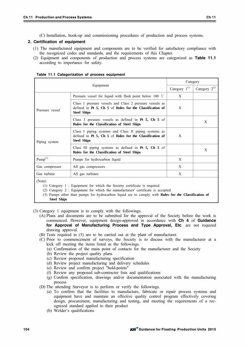
Ch 11 Production and Process Systems Ch 11
104 Guidance for Floating Production Units 2015
Table 11.1 Categorization of process equipment
EquipmentCategory
Category 1(1) Category 2(2)
Pressure vessel
Pressure vessel for liquid with flash point below 100 ℃ X
Class 1 pressure vessels and Class 2 pressure vessels as defined in Pt 5, Ch 5 of Rules for the Classification of Steel Ships
X
Class 3 pressure vessels as defined in Pt 5, Ch 5 of Rules for the Classification of Steel Ships
X
Piping system
Class I piping systems and Class II piping systems as defined in Pt 5, Ch 5 of Rules for the Classification of Steel Ships
X
Class III piping systems as defined in Pt 5, Ch 5 of Rules for the Classification of Steel Ships
X
Pump(3) Pumps for hydrocarbon liquid X
Gas compressor All gas compressors X
Gas turbine All gas turbines X
(Note)(1) Category 1 : Equipment for which the Society certificate is required.(2) Category 2 : Equipment for which the manufacturers' certificate is accepted.(3) Pumps other than pumps for hydrocarbon liquid are to comply with Rules for the Classification of
Steel Ships
(C) Installation, hook-up and commissioning procedures of production and process systems.
2. Certification of equipment
(1) The manufactured equipment and components are to be verified for satisfactory compliance with the recognized codes and standards, and the requirements of this Chapter.
(2) Equipment and components of production and process systems are categorized as Table 11.1 according to importance for safety.
(3) Category 1 equipment is to comply with the followings.(A) Plans and documents are to be submitted for the approval of the Society before the work is
commenced. However, equipment design-approved in accordance with Ch 4 of Guidance for Approval of Manufacturing Process and Type Approval, Etc. are not required drawing approval.
(B) Tests required in (5) are to be carried out at the plant of manufacturer.(C) Prior to commencement of surveys, the Society is to discuss with the manufacturer at a
kick off meeting the items listed as the followings.(a) Confirmation of the main point of contacts for the manufacturer and the Society (b) Review the project quality plans(c) Review proposed manufacturing specification(d) Review project manufacturing and delivery schedules(e) Review and confirm project "hold-points"(f) Review any proposed sub-contractor lists and qualifications(g) Confirm specification, drawings and/or documentation associated with the manufacturing
process(D) The attending Surveyor is to perform or verify the followings.
(a) To confirm that the facilities to manufacture, fabricate or repair process systems and equipment have and maintain an effective quality control program effectively covering design, procurement, manufacturing and testing, and meeting the requirements of a rec-ognized standard applied to their product
(b) Welder’s qualifications
Ch 11 Production and Process Systems Ch 11
Guidance for Floating Production Units 2015 105
(c) Welding procedure specifications and corresponding weld procedure qualification records (d) To verify material certificates(e) To survey fit-up prior to major weldments(f) To survey final weldments(g) To witness, as far as deemed necessary, nondestructive examination tests of welds and
to review records of nondestructive examinations.(h) To review records of post-weld heat treatment, in particular for piping subjected to pres-
surized sour service and subject to NACE MR0175/ISO 15156 requirements(i) To verify dimensions are as shown on approved drawings(j) To check dimensional tolerances and alignment of mating surfaces(k) To witness pressure and proof-load testing of equipment and unit as specified in the
fabrication procedures. (l) To witness final testing and functional testing of subassemblies and completed units, as
specified in the fabrication procedures.(m) To verify all purged and pressurized systems, motor controllers, SCR banks, consoles
and instrumentation and control panels are in compliance with approved drawings.(n) To carry out other inspections as agreed upon during prefabrication meeting(o) To review and approval final manufacturing Data Book and issue final survey report or
certificate and confirm compliance with approved drawings.(4) For category 2 equipment, manufacturers' certificate containing the following data is to be
submitted.(A) Equipment specification(B) statement to confirm that their products are designed, manufactured and tested in accordance
with the recognized codes and standards, and the requirements of this Chapter(C) Operating limitation of the equipment(D) Test record
(5) Equipment of production and process systems are to be tested in accordance with the following.(A) Pressure vessel
(a) Each vessel is to be subjected to a hydrostatic test which at every point in the vessel is at least equal to 1.3 times the maximum allowable working pressure.
(b) For pressure vessels that cannot be hydraulically tested, a pneumatic test equal to 1.1 times the maximum allowable working pressure is to be performed.
(B) Pump(a) A hydrostatic test is to be performed at a minimum of 1.5 times the design pressure.(b) An performance test of the pump is to be performed.
(C) Compressor(a) A hydrostatic test is to be performed at a minimum of 1.5 times the design pressure.(b) An performance test of the pump is to be performed.(c) A leakage test is to be performed. Each compressor intended for toxic or flammable gas
service is to be pressurized with an inert gas.(D) Gas turbine
(a) A hydrostatic test is to be performed at a minimum of 1.5 times the design pressure.(b) An performance test of the pump is to be performed.
(E) Piping systems(a) A hydrostatic test is to be performed at 1.5 times the design pressure or 3.5 kg/cm2 (50
psig), whichever is greater. (b) For all joints including welds, a leakage test is to be performed with uninsulated and
exposed(c) Where it is necessary to perform a pneumatic leak test, the test pressure is to be 1.1
times the design pressure.(F) Generators and motors
(a) Check windings for dryness. It is recommended that space heating be operated for a sufficient time prior to start-up to assure dryness.
(b) Measurement of stator insulation resistance to the motor or generator frame is to be made with an instrument applying a minimum of 600 V across the insulation. The sug-gested minimum insulation resistance is 2 M and new or rebuilt machines are to pro-vide at least 10 M in insulation resistance readings.
(c) If generators are to be operated in parallel, check their phase rotation and the synchro-nizing circuits for proper operation.
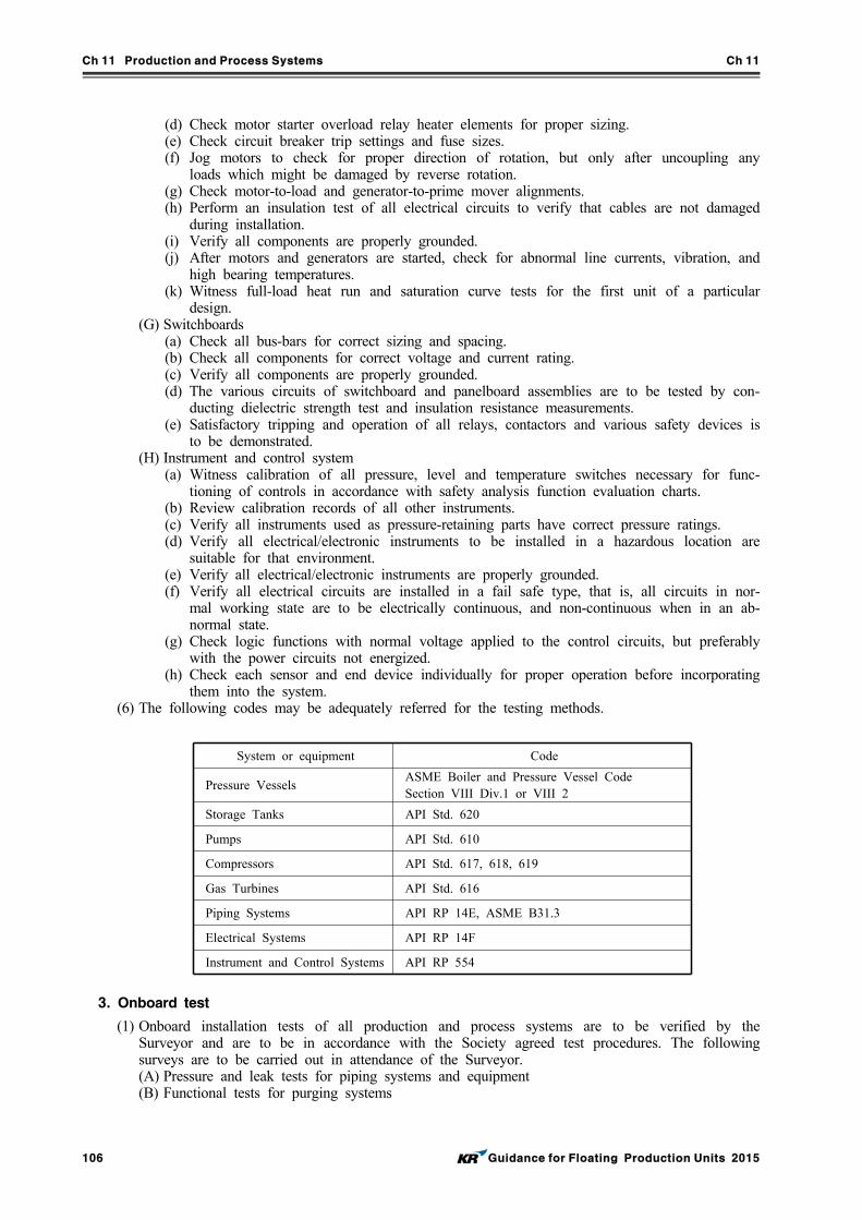
Ch 11 Production and Process Systems Ch 11
106 Guidance for Floating Production Units 2015
System or equipment Code
Pressure VesselsASME Boiler and Pressure Vessel Code Section VIII Div.1 or VIII 2
Storage Tanks API Std. 620
Pumps API Std. 610
Compressors API Std. 617, 618, 619
Gas Turbines API Std. 616
Piping Systems API RP 14E, ASME B31.3
Electrical Systems API RP 14F
Instrument and Control Systems API RP 554
(d) Check motor starter overload relay heater elements for proper sizing.(e) Check circuit breaker trip settings and fuse sizes.(f) Jog motors to check for proper direction of rotation, but only after uncoupling any
loads which might be damaged by reverse rotation.(g) Check motor-to-load and generator-to-prime mover alignments.(h) Perform an insulation test of all electrical circuits to verify that cables are not damaged
during installation. (i) Verify all components are properly grounded.(j) After motors and generators are started, check for abnormal line currents, vibration, and
high bearing temperatures.(k) Witness full-load heat run and saturation curve tests for the first unit of a particular
design.(G) Switchboards
(a) Check all bus-bars for correct sizing and spacing. (b) Check all components for correct voltage and current rating.(c) Verify all components are properly grounded.(d) The various circuits of switchboard and panelboard assemblies are to be tested by con-
ducting dielectric strength test and insulation resistance measurements.(e) Satisfactory tripping and operation of all relays, contactors and various safety devices is
to be demonstrated.(H) Instrument and control system
(a) Witness calibration of all pressure, level and temperature switches necessary for func-tioning of controls in accordance with safety analysis function evaluation charts.
(b) Review calibration records of all other instruments. (c) Verify all instruments used as pressure-retaining parts have correct pressure ratings.(d) Verify all electrical/electronic instruments to be installed in a hazardous location are
suitable for that environment.(e) Verify all electrical/electronic instruments are properly grounded.(f) Verify all electrical circuits are installed in a fail safe type, that is, all circuits in nor-
mal working state are to be electrically continuous, and non-continuous when in an ab-normal state.
(g) Check logic functions with normal voltage applied to the control circuits, but preferably with the power circuits not energized.
(h) Check each sensor and end device individually for proper operation before incorporating them into the system.
(6) The following codes may be adequately referred for the testing methods.
3. Onboard test
(1) Onboard installation tests of all production and process systems are to be verified by the Surveyor and are to be in accordance with the Society agreed test procedures. The following surveys are to be carried out in attendance of the Surveyor.(A) Pressure and leak tests for piping systems and equipment(B) Functional tests for purging systems
Ch 11 Production and Process Systems Ch 11
Guidance for Floating Production Units 2015 107
(C) Functional tests for utility systems such as power generators, process support facilities, in-strument air systems, cooling water systems, etc.
(D) Functional tests for fire fighting and safety systems such as fire pumps, fixed fire fighting systems, portable fire extinguishers, lifesaving equipment, etc.
(E) Functional tests for detection and alarm such as fire detection systems, gas detection sys-tems, fire and gas panel, ESD systems, etc.
(F) Functional tests for process systems such as flare systems, instrumentation and control sys-tems, safety shutdown valves, process components, etc.
4. Start-up procedure
Air or other fluid is to be displaced from the process systems prior to start-up. The Surveyor is to be permitted access to suitable vantage points to verify that the startup procedures are satisfactorily accomplished. The Surveyor is to observe the facilities operating at the initial production capacity for at least a 12 hour period. As applicable, the Surveyor is also to observe the facilities operating at various capacities under various conditions.
Section 2 Design of Process Systems
201. General
1. Process systems are to be arranged so that one single maloperation or malfunction will not lead to critical situations for personnel or the unit.
2. Due consideration is to be given to the well fluid properties, such as presence of hydrogen sulfide, carbon dioxide, etc., for selection of materials.
3. Equipment and piping of process system are to be designed with considering maximum pressure and temperature that may occur during operation, and corrosion property. In addition, the effects of operational conditions such hydrate formation, water hammers and slug are to be taken into account.
202. Separator system
1. The separators are to have sufficient capacity to separate the components of the well stream, and effective means for removal of sand and water.
2. Design of separator and separator control system shall include consideration for list and rolling of the unit, where relevant.
3. The separators are to comply with relevant requirements in 302. and 304.
203. Gas treatment and compression system
1. Liquid scrubbers with mist pad are to be installed immediately upstream of gas compressors. The compressor is to be tripped or otherwise protected if liquid levels reach an unacceptable level with-in an upstream scrubber.
2. Scrubbers are to comply with requirements in 302.
3. Gas coolers in systems with significant pressure differential between the gas and cooling medium side are to be fitted with quick acting relief devices in accordance with API RP 521.
4. Compressor seal systems are to be monitored for leakage. The compressor is to be automatically tripped and depressurised if unacceptable leaks or other malfunctions are detected.
5. Location of vent points from the glycol regeneration re-boiler is to include consideration of emis-sions of harmful substances and their effect on personnel.
204. Piping systems
1. Process piping design, selection of valves, fittings and flanges, are to be in accordance with API RP 14E, ASME B31.3 and other recognized standards.
Ch 11 Production and Process Systems Ch 11
108 Guidance for Floating Production Units 2015
2. Sections of piping systems that can be isolated with block valves are to be provided with thermal relief valves with set point at 120% of design pressure to protect the piping from overpressure caused by solar heating or exposure to fire.
3. Flexible hoses
(1) Hose assemblies may be installed between two points where flexibility is required and is to be type approved by the Society.
(2) Hoses carrying flammable fluids are to incorporate a single, double or more closely woven in-tegral wire braid or other suitable material reinforcement.
(3) Hoses carrying flammable fluids are to be of fire-resistant type. Fire resistance is to be demon-strated by testing to Ch 3, Sec 17, Table 3.17.1 of Guidance for Approval of Manufacturing Process and Type Approval, Etc.
4. Plastic pipe
(1) Plastic pipe is to comply with Pt 5, Annex 5-6 of Rules for the Classification of Steel Ships.
(2) Plastic pipe used in the piping systems for conveying hydrocarbon fluid is to be Level 1 of fire endurance.
205. Electrical systems
Electrical systems are to comply with Ch 10, Sec 1.
206. Control systems
1. Control systems are to comply with Ch 10, Sec 2 in addition to requirements in this Article.
2. The process control system used to maintain process variables within normal operating ranges is to be capable of accommodating a reasonable range of abnormal or transient conditions without creat-ing an upset condition.
3. Essential process parameters such as flow rate, pressure, temperature and liquid level are to be au-tomatically monitored and controlled, and the abnormal conditions are to be alarmed with visual and audible devices.
4. For computer-based Systems, the computer system for monitoring alarms and control is to include redundancy arrangements in order to maintain continued operation of the hydrocarbon process system.
207. Safety systems
1. The safety system is to be provided with two levels of protection to prevent or minimize the ef-fects of an equipment failure within the process. The two levels of protection are to be independent of the control devices used in normal process operation. The two levels are to be provided by functionally different types of safety devices wider spectrum of coverage. The two levels are to be categorized by primary and secondary and to comply with API RP 14C, paragraph 3.4.
2. The emergency shutdown system for process systems is to be provided in accordance with 209. and API RP 14C, Appendix C.
3. Safety Analysis Tables (SAT) and Safety Analysis Checklists (SAC) for each process component, in accordance with API RP I4C, are to be submitted to the Society.
4. Safety Analysis Function Evaluation (SAFE) Charts, in accordance with API RP I4C, are to be submitted to the Society.
208. Pressure relieving and hydrocarbon disposal systems
1. Pressure relief valves are to be installed to protect all pressure vessels and equipment from over-pressurization. Pressure relief valves are to be sized and installed in accordance with API RP 520 and ASME Section VIII, Division 1 Appendix M.
Ch 11 Production and Process Systems Ch 11
Guidance for Floating Production Units 2015 109
2. Pressure relief valves in hydrocarbon gas service are to discharge to one or more closed relief headers for atmospheric discharge at either a flare or vent. Such flare or vent discharges are to meet the requirements of Par 6.
3. Pressure relief valves in liquid hydrocarbon service are to discharge to a tank, pump suction or closed drain system.
4. The use of rupture discs is limited to the following: (1) In gas or gas/liquid service, rupture discs may be utilized only as backup to pressure relief
valves and they are sized for the maximum relieving conditions. (2) In liquid service, rupture discs may be utilized only as backup to pressure relief valves that are
sized for the maximum relieving condition. They may be installed as primary relief devices for non-flammable, non-hazardous liquids at relieving pressures no greater than 1.0 MPa.
5. Vapor Depressurizing systems are to comply with the following:(1) An emergency vapor depressurizing system is to be provided for all equipment processing light
hydrocarbon with operating pressures of 1.75 MPa and above (2) To gain rapid control of a situation in which the source of a fire is the leakage of flammable
fluids from the equipment to be depressurized, the equipment is to be depressurized to 0.7 MPa. In cases where the equipment is handling high pressure and large inventories of hydrocarbon, and depressurizing to 0.7 MPa is impractical, it is acceptable to depressurize to 50% of the equipment design pressure if such depressurization is achieved within 15 minutes. Equipment is to designed with ample margin of safety to prevent the vessel from failing due to overheating.
6. Flares and Vents are to comply with the following:(1) Flares and vents for hydrocarbon gas disposal are to be located with respect to prevailing
winds. This is to limit exposure of personnel, equipment to vented gas, flare exhaust, or flame radiation.
(2) Worst-case atmospheric conditions are to be used for radiation and gas dispersion calculations. Flame radiation calculations are normally to assume a strong wind as a worst-case condition. Dispersion calculations are normally to assume still air and low vent velocity as a worst-case condition.
(3) When a venting system is selected for disposal of hydrocarbon vapors, a vent snuffing system is to be provided to extinguish vented gases, should they ignite.
(4) The flare system is to be provided with means for purging sufficiently (below 5% of oxygen content) before ignition to prevent explosion inside the flare system.
209. Spill containment, open and closed drain systems
1. Spill containment
(1) Spill containment is to be provided in areas subject to hydrocarbon liquid or chemical spills, such as areas around process vessels and storage tanks with drain or sample connections, pumps, compressors, engines, glycol systems, oil metering units, and chemical storageareas.
(2) Where equipment is protected by a fixed foam fire extinguishing system, a minimum of 150mm coaming is to be provided.
2. Open drain piping
(1) Each containment area, as well as any other plated deck or skid area subject to rainwater or other liquid accumulation, is to be equipped with drains connected to an open drain system, and installed and located so as to prevent the accumulation of standing liquid.
(2) Open drain piping is to be self-draining with a slope of not less than 1:100. Lines are to be sized for gravity drainage without backup or overflow.
(3) Cleanouts or flushing connections are to be provided for removal of sediment or solids from open drains subject to potential blockage.
(4) Open drains are to be piped to convey the fluids, by gravity or pumping, to oily water treat-ment or final disposal location.
(5) Drains from classified and unclassified areas are to be separate.
3. Closed drain systems
(1) The drain vessel is to be provided with pressure relief valves, which are to be sized to handle the maximum flow of gas or liquid that could occur under blocked outlet condition.
Ch 11 Production and Process Systems Ch 11
110 Guidance for Floating Production Units 2015
(2) Drains or liquid relief from vessels containing non-toxic, non-flammable liquids, may be con-nected to an unclassified open drain piping system if the open drain system is sized to accom-modate these additional drains.
210. Packaged process units
1. Skid structures
(1) The skid structure is to be sufficiently rigid to support the mounted equipment and piping and, as required, to permit lifting during shipment without damage to the equipment or piping.
(2) Structural design calculations for skid units with a center of gravity height of more than 1.5 m , or a maximum operating weight in excess of 10 tons, calculated in dry conditions, are to be submitted to the Society for review.
2. Drip pans
(1) Drip pans are to be provided to contain liquid spills and leaks from skid mounted equipment and piping, and to drain the liquid with adequate slope into open drain systems.
(2) A minimum 150 mm coaming around the entire perimeter of a skid is to be provided.(3) A spill containment with less than 150 mm coaming arrangement is subject to special
consideration. (4) Calculations showing sufficient spillage containment for the skid are to be submitted to the
Society for verification. (5) Skid beams that extend above the drip pan may be considered as a part of the coaming, pro-
vided that the drip pan is seal-welded to the skid beams.
Section 3 Process System Equipment
301. General
This Section provides requirements for process equipment that are typically utilized in the unit.
302. Pressure vessels
1. Pressure vessels are to be designed, constructed, and tested in accordance with the ASME Boiler and Pressure Vessel Code Section VIII Division 1 or Division 2 or other recognized standards.
2. Low melting point or brittle materials such as cast iron, aluminum, brass, copper, or fiberglass, are not to be utilized in pressure retaining parts of vessels containing flammable or toxic fluids.
3. Supports and insulation of vessels subject to change in temperature are to be designed to accom-modate the resulting thermal movement.
303. Heat exchangers
1. Process heat exchangers with a design pressure in excess of 0.1 MPa and handling flammable fluids are subject to the requirements of 302. and the following applicable requirements:
2. Tubular heat exchangers are to comply with applicable sections of ASME Boiler and Pressure Vessel Code Section VIII, Division 1 or Division 2, TEMA Standards or API Std. 660.
3. Plate and frame exchangers may be employed for handling flammable liquid, with the following re-strictions: (1) Safety or protective devices are to be provided as required in accordance with of API RP 14C,
Appendix A, A10.(2) Each exchanger is to be provided with an exchanger enclosure, protective wall, shield or similar
barrier, capable of containing spray in case of gasket leakage during operation. (3) Each exchanger is to be provided with spill containment and drain capable of handling a liquid
release of at least 10% of the maximum flammable stream flowrates. 4. Air-cooled heat exchangers are to comply with API Std. 661.
Ch 11 Production and Process Systems Ch 11
Guidance for Floating Production Units 2015 111
304. Fired vessels
1. All fire-tube type fired vessels, with a shell operating pressure greater than 0.1 MPa, are to be de-signed in accordance with Section I of ASME Boiler and Pressure Vessel Code. Fired vessel shells, coils or other equipment designed in accordance with ASME Boiler and Pressure Vessel Code are to conform to all applicable requirements of 302.
2. Indirect fired water bath heaters with working pressures lower than 0.1 MPa are to be designed and fabricated in accordance with API Spec. 12K.
3. Direct fired vertical or horizontal emulsion treaters are to be designed and constructed in accord-ance with API Spec. 12L.
4. Where burner ignition or light-off is part of an automatic sequence, the following control functions are to be provided: (1) Automatic timed purge interval prior to admitting pilot fuel. Purge may be by fan if equipped,
or by time delay to allow natural draft purge.(2) Firing limit on a trial for ignition (15 seconds maximum) on each attempted pilot light-off.(3) Confirmation of pilot lighting prior to admitting main burner fuel.
5. Each burner designed for manual light-off of the pilot is to be designed to allow an operator to light the pilot from a location which limits his exposure to flame flashback, should it occur. Burners are to be equipped with a sight-glass suitable for verifying pilot light-off and for viewing of main flame.
6. Combustion air intakes for fired vessels are to be located in a safe area.
7. Any fired vessel installed within a firewall is to be arranged with means of shutdown from outside the firewall enclosure.
305. Compressors
1. Gas compressors are to comply with applicable API standards according to their types. Compressors rated for less than 0.7 MPa and 28.3 mmin can be accepted on the basis of manufacturer’s decla-ration of conformity and test reports.
2. A fusible plug fire detection system, directly activating the emergency shutdown system, is to be installed in the compressor package. The emergency shutdown system is to be interlocked to shut-down the compressor.
306. Pumps
1. Centrifugal pumps intended for hydrocarbon service are to comply with API Std 610. Centrifugal pumps having stuffing box pressures in excess of 1.4 MPa are to be provided with either mechan-ical seals with alarm or mechanical seals with means to collect and contain seal leakage.
2. Pumps rated for 0.7 MPa and 757 min or less may be accepted for hydrocarbon service, on the basis of a manufacturer’s declaration of conformity with the requirement of API Std. 610.
3. Pumps rated above 0.7 MPa and 757 min are to meet the following requirements: (1) The manufacturer is to supply a manufacturer’s declaration of conformity to API Std. 610 to
the Society and is to include documentation on the seal arrangement of the pump. (2) The manufacturer is to submit a statement indicating any system or components not in com-
pliance with the requirements, detailing and clarifying all deviations to API Std. 610, paragraph 6.1.5 to the Society.
Ch 11 Production and Process Systems Ch 11
112 Guidance for Floating Production Units 2015
Section 4 Process Support Systems
401. General
1. Requirements in this Section apply to systems that do not handle production fluid, but complement the process systems operations, such as fuel systems, compressed air systems, cooling water systems and etc. A typical list of process support systems includes the following: (1) Purging system(2) Heating & cooling systems(3) Fuel oil system(4) Compressed air system(5) Inert gas systems(6) Hydraulic System
2. Plans and data to be submitted
(1) Piping and Instrument Diagrams including piping specification.(2) Process equipment documentation (3) Specifications for internal combustion engines and turbines
3. Process support piping design and selection of valves and fittings are to be in accordance with API RP 14E, ASME 31.3 or other recognized standards.
4. Machinery and equipment are to be arranged in accordance with safety requirements in API RP 14J.
402. Design of process support system
1. Control and utility air system
(1) Control and utility air may be supplied by a single air compressor or by a separate compressor for each service. When using a single compressor for both services, controls are to be provided to give priority to control air requirements.
(2) Control air is to be oil-free and dried.(3) Air compressor suctions are to be at least 3 m from hazardous areas.
2. Control gas system
(1) Gas used for control systems is to be passed through a gas scrubber to remove entrained liquid. (2) Gas containing hydrogen sulfide is not to be used as instrument gas.(3) Where gas is used for instrument systems, the area classification in way of these instruments is
to be in accordance with API RP 505.
3. Use of produced gas as fuel
Use of produced gas as fuel is to comply with Ch 9, Sec 3, 304. and 305.
4. Purging system for process equipment
(1) Process equipment and systems are to be purged prior to initial startup. (2) They are also to be purged when being put back into service after shutdown, if there is a pos-
sibility of oxygen entering the system during shutdown. (3) Units not equipped for storage of liquid hydrocarbon may only require temporary inert gas stor-
age containers. (4) The oxygen content of the inert gas used is not to exceed 5% by volume. (5) Oxygen monitoring equipment is to be provided to monitor oxygen levels in the inert gas
supply.
5. Fuel oil system
(1) Fuel oil pumping arrangements are to be completely separate from other pumping systems, and are not to be connected to other piping systems.
(2) Fuel oil transfer pumps are to be fitted with local and remote controls so they may be stopped in case of an emergency. Remote controls are to be located in a space not affected by fire at the pump locations.
(3) A containment at least 150 mm high is to be provided at pump areas and arranged to the open drain system.
Ch 11 Production and Process Systems Ch 11
Guidance for Floating Production Units 2015 113
(4) Oil fuel pipes, which, if damaged, would allow oil to escape from a fuel oil tank having a ca-pacity of 500 and above situated above the double bottom, shall be fitted with a cock or valve directly on the tank capable of being closed from a safe position outside the space con-cerned in the event of a fire occurring in the space in which such tanks are situated. Gray cast iron valves are not to be used as shutoff valves for fuel oil tanks.
(5) Non-metallic expansion joints and hoses for use in fuel oil systems are only allowed at machi-nery connections, provided they are in an easily accessible position, and pass the API Spec 16C fire test.
6. Hydraulic system
(1) High flash point hydraulic fluids are to be used, unless a specific system design requires the use of low flash point fluids.
(2) When low flash point fluids are used, precautions are to be taken to minimize fire hazard, by insulating nearby hot surfaces.
(3) Non-metallic hoses used for oil based hydraulic fluid in all hydraulic control systems must pass API Spec 16C fire test.
7. Lubricating oil system
(1) The lubricating oil piping is to be entirely separated from other piping systems. (2) Normally opened valves on lubricating oil storage tanks are to comply with the requirements of 5 (4).
(3) Turbines (A) Turbines are to be provided with a means of automatically shutting off the steam or gas
turbine fuel supply upon failure of the lubricating oil system.(B) Indicators
(a) Indicators are to be fitted to allow monitoring of the pressure and temperature of the water inlet and oil outlet of the oil coolers.
(b) Pressure systems are to be fitted with low-pressure alarm. (c) Sump and gravity tanks are to be provided with suitable gauges for determining the lev-
el of oil within the tank.(C) Strainers and filters
(a) For auxiliary turbines, a magnetic strainer and fine mesh filter (strainer) are to be pro-vided in the lubricating oil piping to the turbine.
(b) Strainers are to be so arranged as to prevent, in the event of leakage, spraying oil onto heated surfaces.
(4) Internal combustion engines (A) The lubricating oil pump is to be of sufficient capacity for the maximum output of the
engine. (B) Lubrication oil filter is to be provided and so arranged as to prevent, in case of leakage,
spraying oil onto heated surfaces. (C) An alarm device with audible and visual signals for failure of the lubricating oil system is
to be fitted.
8. Chemical injection system
(1) Non-return valves shall be installed at injection points to production systems.(2) The design pressure of a chemical injection pump is, as a minimum, to be the same as the
system into which it injects.(3) Flame arrester is to be provided to flammable or combustible tank vent.
9. Heating and cooling systems
(1) The medium used for heating or cooling any hydrocarbon system is to be contained solely within the hazardous area.
(2) The return line of the heating or cooling system is to be provided with means to detect any hydrocarbon contamination.
10. Water Injection, gas injection and gas lift systems
(1) A non-return valve and an automatic shutdown valve are to be fitted at the injection point to the well.
(2) Water injection systems on units which are intended to operate in areas with ambient design temperatures below -5°C are to be fitted with winterisation to prevent freezing during periods of shutdown.
Ch 11 Production and Process Systems Ch 11
114 Guidance for Floating Production Units 2015
(3) If produced water is to be re-injected into the reservoir, areas in which overboard dump lines and drain lines from water injection pump seals are installed are to be considered as hazardous area in accordance with Ch 7.
403. Process support system equipment
1. Pressure vessels
Pressure vessels are to be designed, constructed, and tested in accordance with the ASME Boiler and Pressure Vessel Code Section VIII Division 1 or Division 2 or other recognized standards.
2. Heat exchangers
(1) Heat exchangers are to comply with applicable sections of ASME Boiler and Pressure Vessel Code Section VIII, Division 1 or Division 2, TEMA Standards or API Std. 660.
(2) Air-cooled heat exchangers are to comply with API Std. 661.
3. Pumps
Pumps are to comply with requirements in Pt 5 of Rules for the Classification of Steel Ships.
4. Internal combustion engines and turbines
(1) The requirements not specified in this Paragraph are to be in accordance with Pt 5, Ch2 of Rules for the Classification of Steel Ships.
(2) Gas turbines are to comply with API Std. 616.(3) Internal combustion engines may not be installed in hazardous area. The installation of Internal
combustion engines may be permitted in Zone 1 and Zone 2, provided that the Society is sat-isfied that sufficient precaution has been taken against the risk of dangerous ignition.
(4) Exhaust outlets of internal combustion engines are to be fitted with suitable spark arresting de-vices and to discharge outside the hazardous areas.
(5) Air intakes for internal combustion engines are to be not less than 3 m from the hazardous areas.
(6) Protection of crankcase are to comply with the following:(A) Ventilation and monitoring
(a) Medium and high speed diesel engines(trunk piston type): (i) Ventilation is to be provided for the crankcase to prevent accumulation of gas. (ii) The crankcase vent is to be led to a safe location in the atmosphere through a
flame arrester. (iii) The crankcase is to be provided with oil mist detection arrangements(or engine
bearing temperature monitors or equivalent devices) obtained type approval.(iv) The crankcase is also to be provided with gas detecting or equivalent equipment.
(b) Low speed diesel engines(crosshead type): (i) The crankcase is to be protected by an oil mist detector or bearing temperature
detector. (ii) Gas detection or equivalent equipment is to be provided for the piston underside
space. (B) Explosion relief valves
(a) The crankcase is to be provided with relief valves of an approved type, for the purpose of relieving the excess pressure in the event of an internal explosion.
(b) The number and the free area of the relief valves are in accordance with Pt 5, Ch2, 203. 4 of Rules for the Classification of Steel Ships.
Ch 12 Import and Export Systems Ch 12
Guidance for Floating Production Units 2015 115
CHAPTER 12 IMPORT AND EXPORT SYSTEMS
Section 1 General
101. Application
1. The requirements in this Chapter apply to production and process system installed in the unit with Import, Export or Import/Export notation specified in Ch 2. For the unit with only Import nota-tion(or Export notation), import system(or export system) requirements apply.
2. The boundary of import and export systems is as the following:(1) The Import System apply to import riser from the import pipe line end manifold(PLEM) to the
input flange of the unit.(2) The Export System apply to export riser from the discharge flanges of the unit to the export
pipe line end manifold.
102. Codes and standards
1. The requirements not specified in this Guidance are to be in accordance with recognized national or international standards.
2. The following standards may be adequately referred as recognized national or international standards.
Standard No. Standard Title
API Spec 17J Specification for Unbonded Flexible Pipe
API RP 17B Recommended Practice for Flexible Pipe
API RP 2RD Design of Risers for Floating Production Systems (FPSs) and Tension-Leg Platforms (TLPs)
API RP 2T Planning, Designing and Constructing Tension Leg Platforms
OCIMF standard Guidelines for the Handling, Storage, Inspection, and Testing of Hoses in the Field.
103. Definition
1. Riser is a subsea rigid or flexible pipe that connects the surface facilities with the sea floor and conveys production fluid.
2. Import pipe line end manifold is the assemblage of pipe, valves and component connecting to the Import Riser and the subsea pipeline or wellhead.
3. Export pipe line end manifold is the assemblage of pipe, valves and component connection be-tween the Export Riser and the product discharge line.
4. Floating hose is a floating conduit used to export hydrocarbons from a point of storage or pro-duction, either an SPM or installation’s manifold to a receiving installation’s manifold for transport.
104. Design considerations
1. The import/export system is to be designed to maintain its integrity under the most unfavorable combination of external loads and internal loads.
2. The dynamic response of the import/export system is to be investigated to the level of detail neces-sary to ensure that interference between the floating production installation and the associated moor-ing system does not affect the integrity of the installation or the import/export system.
3. The riser is to survive the maximum installation offset, as defined in Ch 6, 203.
Ch 12 Import and Export Systems Ch 12
116 Guidance for Floating Production Units 2015
105. Classification survey during construction
1. The following Plans and data are to be submitted to the Society for review:(1) Site plan indicating bathymetric features, the location of obstructions to be removed, the location
of permanent manmade structures and other important features related to the characteristics of the sea floor
(2) Material specifications for the import/export system(3) Pipe manufacture, testing and quality control procedures(4) Flow diagrams indicating temperature and pressure profiles(5) Specifications and plans for instrumentationf, control systems and safety devices(6) Specifications and plans for installation, field testing, inspection, anticipated component replace-
ment and continued maintenance of the riser system(7) Environmental and geotechnical report
2. The following surveys are to be carried out during the fitting out of import and export systems.(1) The installation of the riser clamps on the buoyancy tank and arch support are to be monitored
to ensure that the riser is adequately secured and not damaged due to excessive tightening of the clamps.
(2) Upon completion of installation, the entire underwater complement of components is to be gen-erally examined by divers or ROVs.
(3) Hydrostatic test of the import and export system is to be performed in accordance with the pro-cedure specified in API RP 2RD and RP 17B.
(4) It is to be verified that the offloading systems(export systems) for units which are permanently and exclusively equipped for such units are fitted out as designed. In such cases, the hose string bend radii, hose flange gaskets, the positioning of navigational aids, the correct locations of break-away coupling, the tightening of the flange bolts are also verified for compliance with the installation procedures.
(5) All navigational aids are to be functionally tested and proven in working order.
Section 2 Design
201. General
The design of the import and export system is to consider all modes of operating, testing, survival and accidental events. The import and export system is to be analyzed to determine its response to the design events. Each individual component is to be examined for its strength and suitability for the service conditions.
202. Rigid risers
1. The analysis of a rigid riser is to follow the appropriate sections of API RP 2RD and API RP 2T for all relevant design load cases.
2. The following items are to be appropriately accommodated in the analysis: (1) Environmental conditions (2) Boundary conditions (3) Riser configuration (4) Riser joint properties (5) Buoyancy devices (6) Installation motion (RAOs) (7) Applicable site conditions (8) Effects of internal contents (9) Pressure testing and accidental conditions
2. Rigid risers are to be designed against the following limits based on the design load cases being investigated. (1) Maximum Stress, Stability and Buckling: Allowable stresses in plain pipe are to be limited, per
API RP 2RD. Overall stability of the riser and local pipe buckling is to be evaluated. (2) Maximum Deflection: Acceptable limits of maximum deflection are to be determined considering
the inherent limitations of riser components, equipment used in the riser and the need to avoid
Ch 12 Import and Export Systems Ch 12
Guidance for Floating Production Units 2015 117
interference with the Floating Installation. (3) Fatigue and Fracture: The riser system is to be designed to ensure that an adequate margin of
safety is available for critical components to counteract the effects of fatigue caused by cyclic fluctuations (due to both internal and external loads) over the anticipated life of the system.
(4) The cumulative damage calculated by the use of Miner’s Rule is to be 0.1 or less for a critical component which cannot be easily inspected or repaired. For non-critical components which can be easily inspected, the cumulative damage should be 0.3 or less.
203. Flexible risers
1. The in-place analysis is to address all design load cases using motions consistent with the mooring analysis.
2. The scope of the in-place analysis, as a minimum, is to include the following:
(1) On-bottom stability for flexible flow lines (2) Static and dynamic analysis for flexible riser (3) A system dynamic analysis to ensure:
(A) Maximum tension and minimum radius of curvature are within the manufacturer’s recom-mendations
(B) Suspended portions of the flexible pipe are not allowed to bounce on the sea floor or expe-rience compression that might cause kinks
(C) Suspended flexible pipes are not allowed to chafe against each other, the installation body or mooring lines
(4) Flow-induced motion analysis(5) Flexible pipe layer stress analysis(6) The stresses in the flexible pipe layers are to comply with the requirements of API Spec 17J
for the applicable design load cases(7) Mechanical gripping devices should not cause damage to the weaker exterior layer(8) Service life analysis(9) Corrosion protection system design
3. Design limits established for the riser system are to be determined in accordance with API RP 17B and confirmed by performance testing during the manufacture of the flexible riser and the asso-ciated components. Where sufficient test data and service history exist to confirm a component’s capability, the Society may consider the acceptance of this documentation in lieu of performance testing.
204. Floating hose
In cases where floating hoses are used to transfer the crude oil from the production unit to carrier or another units, such floating hoses are to comply with the following requirements.(1) Breakaway couplings are to be provided with shut off valves in each floating hose string in or-
der to minimize the hazard of oil pollution in emergency situations.(2) Floating hoses are to comply with recognized standard (OCIMF, API, MARPOL, etc.), and to
hold appropriate certificates for necessary tests and inspections.(3) The construction of connections between hoses and the unit (bolting, gaskets, etc.) are to be
suitable for their intended service.
GUIDANCE FOR FLOATING
PRODUCTION UNITS
Published by
KR
36, Myeongji ocean city 9-ro, Gangseo-gu,BUSAN, KOREA
TEL : +82 70 8799 7114
FAX : +82 70 8799 8999
Website : http://www.krs.co.kr
CopyrightⒸ 2015, KR
Reproduction of this Guidance in whole or in parts is pro-hibited without permission of the publisher.