flight training instructionthe academic theory, the easier it is for you to learn maneuvers in the...
TRANSCRIPT

NAVAL AIR TRAINING COMMAND
NAS CORPUS CHRISTI, TEXAS CNATRA P-457 Rev (01-15)
FLIGHT TRAINING
INSTRUCTION
CONTACT
HELICOPTER ADVANCED PHASE
TH-57C
2015


iii
FLIGHT TRAINING INSTRUCTION
FOR
CONTACT, HELICOPTER ADVANCED PHASE
TH-57C
P-457

iv
LIST OF EFFECTIVE PAGES
Dates of issue for original and changed pages are:
Original...0...15 Aug 02 (this will be the date issued)
Revision…1…12 Feb 04
Revision…2…15 Dec 06
Change Transmittal…1…08 Sep 08
Revision…3…01 Aug 11
Change Transmittal…1…06 Feb 13
Change Transmittal…2…19 Jun 14
Revision…4…25 Feb 15
TOTAL NUMBER OF PAGES IN THIS PUBLICATION IS 146 CONSISTING OF THE FOLLOWING:
Page No. Change No. Page No. Change No.
COVER 0 6-1 – 6-24 0
LETTER 0 7-1 – 7-7 0
iii -- ix 0 7-8 (blank) 0
x (blank) 0 8-1 – 8-15 0
1-1 – 1-8 0 8-16 (blank) 0
2-1 – 2-5 0 A-1 0
2-6 (blank) 0 A-2 (blank) 0
3-1 – 3-7 0 B-1 – B-5 0
3-8 (blank) 0 B-6 (blank) 0
4-1 – 4-41 0
4-42 (blank) 0
5-1 – 5-16 0

v
INTERIM CHANGE SUMMARY
The following Changes have been previously incorporated in this manual:
CHANGE
NUMBER REMARKS/PURPOSE
1 Changes made per transmittal letter (02-06-13)
2 Changes made per transmittal letter (06-19-14)
The following interim Changes have been incorporated in this Change/Revision:
INTERIM
CHANGE
NUMBER
REMARKS/PURPOSE
ENTERED BY
DATE

vi
TABLE OF CONTENTS
LIST OF EFFECTIVE PAGES .................................................................................................. iv
INTERIM CHANGE SUMMARY ...............................................................................................v TABLE OF CONTENTS ............................................................................................................ vi TABLE OF FIGURES ................................................................................................................. ix
CHAPTER ONE – CONTACT ................................................................................................ 1-1
100. INTRODUCTION .................................................................................................. 1-1
101. THE FLIGHT INSTRUCTOR ............................................................................... 1-2 102. THE AIRCRAFT .................................................................................................... 1-2 103. COCKPIT FAMILIARIZATION ........................................................................... 1-2 104. C0301 ...................................................................................................................... 1-2
105. PHYSICAL CONDITION ...................................................................................... 1-2 106. CREW RESOURCE MANAGEMENT (CRM) ..................................................... 1-3
107. CREW RESOURCE MANAGEMENT APPLIED TO THE FLIGHT
SEQUENCE ............................................................................................................ 1-6
CHAPTER TWO – FUNDAMENTALS OF HELICOPTER CONTROL .......................... 2-1 200. INTRODUCTION .................................................................................................. 2-1
201. CYCLIC CONTROL .............................................................................................. 2-1 202. COLLECTIVE CONTROL .................................................................................... 2-2
203. ANTI-TORQUE PEDALS ..................................................................................... 2-3 204. TWIST GRIP (THROTTLE) .................................................................................. 2-4
CHAPTER THREE – BASIC MANEUVERS ........................................................................ 3-1 300. INTRODUCTION .................................................................................................. 3-1 301. ATTITUDE FLYING ............................................................................................. 3-1 302. ATTITUDE CONTROL AND AIRSPEED ........................................................... 3-2
303. ATTITUDE CONTROL AND COORDINATED TURNS ................................... 3-2 304. POWER CONTROL AND RESULTING ALTITUDE, CLIMB, OR DESCENT 3-4
305. TURBULENCE AND WINDS .............................................................................. 3-5 306. CROSSWIND CORRECTIONS ............................................................................ 3-5
307. SCAN ...................................................................................................................... 3-6
CHAPTER FOUR – FLIGHT TRAINING MANEUVERS - LOW WORK ....................... 4-1 400. INTRODUCTION .................................................................................................. 4-1 401. VERTICAL TAKEOFF .......................................................................................... 4-1
402. HOVER ................................................................................................................... 4-3 403. VERTICAL LANDING.......................................................................................... 4-5
404. TURN ON THE SPOT/CLEARING TURN .......................................................... 4-6 405. HOVER TAXI/AIR TAXI .................................................................................... 4-10 406. SQUARE PATTERNS ......................................................................................... 4-12 407. TRANSITION TO FORWARD FLIGHT ............................................................ 4-14 408. MAXIMUM LOAD TAKEOFF (SIMULATED) ................................................ 4-17 409. NO HOVER TAKEOFF ....................................................................................... 4-18

vii
410. NORMAL CRUISE .............................................................................................. 4-19
411. CLIMBS ................................................................................................................ 4-20 412. NORMAL DESCENTS ........................................................................................ 4-21 413. LEVEL SPEED CHANGE/CONTACT STAGE ................................................. 4-22
414. TURN PATTERN/CONTACT STAGE ............................................................... 4-24 415. NORMAL APPROACH ....................................................................................... 4-25 416. MODIFIED NORMAL APPROACH .................................................................. 4-28 417. STEEP APPROACH ............................................................................................ 4-29 418. WAVEOFF – POWER ON .................................................................................. 4-31
419. WAVEOFF – POWER OFF ................................................................................. 4-32 420. QUICK STOP FROM A HOVER ........................................................................ 4-34 421. SLIDING LANDING ........................................................................................... 4-36 422. NO HOVER LANDING ....................................................................................... 4-37
423. HYDRAULIC BOOST-OFF APPROACH .......................................................... 4-39 424. STAB OFF APPROACH ...................................................................................... 4-40
CHAPTER FIVE – AUTOROTATION MANEUVERS ....................................................... 5-1 500. INTRODUCTION .................................................................................................. 5-1 501. SIMULATED ENGINE FAILURE IN A HOVER AND HOVER TAXI (CUT
GUN)....................................................................................................................... 5-1
502. AUTOROTATIONS ............................................................................................... 5-4 503. SIMULATED ENGINE FAILURE AT ALTITUDE........................................... 5-12
504. CHECKING POWER AVAILABLE AT ALTITUDE ........................................ 5-15
CHAPTER SIX – DEMONSTRATION AND IUT MANEUVERS...................................... 6-1 600. INTRODUCTION .................................................................................................. 6-1
601. LOW RPM RECOVERY (IUT ONLY) ................................................................. 6-1 602. SIMULATED ENGINE FAILURE ON TAKEOFF (DEMO ONLY) .................. 6-2 603. MAXIMUM GLIDE AUTOROTATION .............................................................. 6-2
604. HIGH SPEED LOW-LEVEL AUTOROTATION (DEMO ONLY) ..................... 6-3 605. SIMULATED FIXED PITCH PEDAL POSITION IN A HOVER – NO YAW ... 6-5
(DEMO ONLY) ...................................................................................................... 6-5 606. SIMULATED COMPLETE LOSS OF T/R THRUST IN A HOVER (DEMO
ONLY) .................................................................................................................... 6-7 607. SIMULATED FIXED PITCH PEDAL POSITION IN A HOVER – LEFT YAW (DEMO ONLY) ...................................................................................................... 6-8 608. SIMULATED FIXED PITCH PEDAL POSITION IN A HOVER – RIGHT YAW (DEMO ONLY) .................................................................................................... 6-11
609. SIMULATED FIXED PITCH PEDAL POSITION AT ALTITUDE– LOW
POWER (DEMO ONLY) ..................................................................................... 6-14
610. SIMULATED FIXED PITCH PEDAL POSITION AT ALTITUDE –HIGH
POWER (DEMO ONLY) ..................................................................................... 6-19
CHAPTER SEVEN – EMERGENCY PROCEDURES ......................................................... 7-1 700. INTRODUCTION .................................................................................................. 7-1 701. LEARNING EMERGENCY PROCEDURES ....................................................... 7-1

viii
702. SINGLE INSTRUMENT INDICATIONS ............................................................. 7-2
703. SIMULATED EMERGENCIES AT ALTITUDE/SITE ........................................ 7-3
CHAPTER EIGHT – NIGHT OPERATIONS ....................................................................... 8-1 800. INTRODUCTION .................................................................................................. 8-1 801. LIMITATIONS ....................................................................................................... 8-1 802. PHYSIOLOGY ....................................................................................................... 8-2 803. PREFLIGHT INSPECTION ................................................................................... 8-3 804. USE OF LIGHTS .................................................................................................... 8-6
805. NIGHT TAKEOFF ................................................................................................. 8-7 806. NIGHT LANDINGS ............................................................................................... 8-8 807. NIGHT HOVERING TECHNIQUES .................................................................... 8-8 808. NIGHT HOVER TAXI ........................................................................................... 8-9
809. NIGHT EMERGENCY PROCEDURES ............................................................... 8-9 810. FORCED LANDINGS ......................................................................................... 8-10
811. NIGHT PRACTICE AUTOROTATIONS ........................................................... 8-10 812. NIGHT PILOTAGE.............................................................................................. 8-10
813. NIGHT LOW ALTITUDE NAVIGATION ......................................................... 8-11
APPENDIX A – GLOSSARY .................................................................................................. A-1 A100. NOT APPLICABLE .............................................................................................. A-1
APPENDIX B – SOLO GUIDELINES ....................................................................................B-1

ix
TABLE OF FIGURES
Figure 3-1 Axes About Which Aircraft Attitude is Controlled ........................................ 3-1
Figure 3-2 Loss of Vertical Lift During Turns................................................................... 3-3 Figure 3-3 Load Factors In Various Angles of Bank During Level Turns ..................... 3-4
Figure 4-1 Effect of Wind on The Lift Vectors .................................................................. 4-7 Figure 4-2 Effect of Wind on The Lift Vectors .................................................................. 4-8
Figure 4-3 Effect of Wind on The Lift Vectors .................................................................. 4-8 Figure 4-4 Effect of Wind on Rate of Turn ........................................................................ 4-9 Figure 4-5 Taxi Signals....................................................................................................... 4-11 Figure 4-6 Normal Approach ............................................................................................ 4-27
Figure 8-1 PAC/PNAC Duties ............................................................................................. 8-6

x
THIS PAGE INTENTIONALLY LEFT BLANK

CONTACT 1-1
CHAPTER ONE
CONTACT
100. INTRODUCTION
In the course of helicopter flight training, you will be required to learn the precision skills that
are characteristic of all naval helicopter pilots. This will require a tremendous amount of
determination, initiative, and perseverance on your part. In return, everyone at this command
will do everything possible to help you accomplish this goal.
Learning to fly helicopters will be one of the most challenging and rewarding endeavors you will
ever undertake. First, you will learn how to hover. That is to hold the aircraft in nearly
motionless flight over a reference point at a constant altitude. Next, you will progress to taxiing
the aircraft from one point to another. You will also practice vertical takeoffs and landings,
normal approaches, and turns about a spot. Later, as you progress and gain further experience in
flying a helicopter, you will be introduced to autorotations and engine failures at altitude.
Following satisfactory completion of the C4390 check ride you will be off for your first solo
flight as an unrestricted aviator.
In order for you to learn what you need about flying helicopters, it is necessary for you to
become intimately familiar with this flight training instruction (FTI). Helicopter training
involves close coordination between academics and flight instruction. The better you understand
the academic theory, the easier it is for you to learn maneuvers in the helicopter. In addition to
the FTI you should consult the following publications:
1. TH-57 NATOPS Flight Manual
2. Engineering, Helicopter, publications
3. Aerodynamics, Helicopter, publications
4. Rotary -Wing Operations Procedures Manual
5. COMTRAWINGFIVEINST 3710.8
6. Master Curriculum Guide, TH-57
7. Squadron SOP
Learning to fly can be defined as developing the proper reaction to an experience in the aircraft.
No one can understand the proper reaction to each step without preparation. A thorough working
knowledge of procedures is essential for your safe and successful completion of flight training.
You must, however, go beyond rote memorization of procedures and strive for a clear
understanding of each maneuver before you get into the cockpit and fly the maneuver.
Remember, the knowledge gained in this stage of your training will be utilized time and time
again throughout your career in naval aviation.

CHAPTER ONE TH-57 CONTACT
1-2 CONTACT
101. THE FLIGHT INSTRUCTOR
The helicopter flight instructors at Whiting Field are among the most highly qualified pilots in
naval aviation today. Their objective is to train professional pilots and they expect you to put
forth your best effort at all times. If your instructor seems to place a great amount of importance
on exactness, it is because he/she is attempting to train you to be as close to perfection as
possible. Sloppy flying and minimal standards are not goals of any instructor pilot. The word
you will hear most from your instructor is “PROCEDURES!” In order for your time in the
aircraft to be devoted to improving your performance, it is imperative you learn, memorize, and
understand the procedural steps required to perform each of the various maneuvers. The
instructor’s job is not to teach you procedures, but to fly. The instructor is well trained and
qualified to teach his/her student, but his/her success requires the student’s complete cooperation.
102. THE AIRCRAFT
The TH-57 “Sea Ranger” will be the helicopter you fly throughout rotary training. The TH-57 is
a single-engine, land-based, utility-type helicopter designed for takeoff and landing on any
reasonably level and firm terrain. The standard seating configuration provides for pilot, co-pilot,
and three passengers. The pilot’s station is on the right side but a full set of flight controls is also
installed on the left side. A Rolls Royce 250-C20J engine powers the helicopter. The engine
weighs 157 pounds and is capable of developing 420 shaft horsepower on a standard day. It is
restricted to 317 shaft horsepower due to transmission limitations.
103. COCKPIT FAMILIARIZATION
Before you climb into the TH-57 for the first flight you will have practiced the use of checklists
and emergency procedures several times. While you are awaiting your opportunity to fly, you
may find yourself without a specific assignment. You can use this time to become familiar with
the cockpit of the aircraft by sitting in it and learning the locations of the various instruments and
switches. Numerous aircraft are available in the squadron hangar for your use. You should
coordinate with Aircraft Issue prior to practicing cockpit procedures or the preflight.
104. C0301
Prior to your first flight, there are several fundamental topics that you, as a student aviator, must
understand if you are to obtain maximum benefit from your helicopter training. C0301 provides
you the opportunity to learn the preflight, meet a Contact flight instructor, and discuss any
questions you might have prior to your first brief. Make your initial appearance, and each
succeeding appearance before an instructor a good one. Bear in mind military courtesy and
discipline are important factors in your training and will continue to be as long as you are a
member of the military service.
105. PHYSICAL CONDITION
Absorbing flying lessons quickly and completely takes physical stamina. Even if you are in top
physical condition, the first few days of training will be fatiguing. Your first flights will not be

TH-57 CONTACT CHAPTER ONE
CONTACT 1-3
long, but they will seem like it. As you become more accustomed to your flight training, you
will find you are more relaxed in the cockpit, and you will not be as tired after your flights.
Mental fatigue is also a condition to consider. Develop a sound and systematic schedule that will
provide maximum utilization of your study, recreation, and rest time. This course is not
programmed to physically and mentally exhaust you; however, you must carefully regulate your
spare time in order to successfully meet the demands of flight training.
106. CREW RESOURCE MANAGEMENT (CRM)
Although there has been a dramatic decrease in the number of military aircraft mishaps due to
better aircraft, improved maintenance procedures, and the NATOPS program there is still a
significant amount of costly assets being lost. Some external factors beyond the control of the
aircrew often adversely impact the mission and cause mishaps. There is nothing an aviator can
do in those situations; however, 50 to 80 percent of all mishaps in the Navy/Marine Corps
involve pilot error. The Navy has instituted the CRM program to educate and train its pilots to
prevent such mishaps. CRM has been implemented in various platforms in the Fleet and is also
being taught in most Fleet Replacement Squadrons. Utilizing and implementing the proper use
of CRM will be the foundation of Naval Aviation in the future.
CRM describes the process of coordinated action among crewmembers which enables them to
interact effectively while performing mission tasks. Good CRM can increase mission
effectiveness by minimizing crew preventable errors, maximizing crew resources, and
optimizing risk management. The Naval Training Systems Center has identified several skills
and behaviors, which influence CRM. These behaviors have been classified into seven basic
areas.
1. Decision Making: the ability to use logical and sound judgment based on the information
available. Factors that promote good decision-making are:
a. Teamwork.
b. Extra time to make a decision.
c. Alert crewmembers.
d. Decision strategies and experience.
2. Assertiveness: the willingness to actively participate and ability to state and maintain your
position. Aircrew members can assert themselves by:
a. Providing relevant information without being asked.
b. Making suggestions.
c. Asking questions as necessary.

CHAPTER ONE TH-57 CONTACT
1-4 CONTACT
d. Confronting ambiguities.
e. Maintaining their position when challenged.
f. Stating opinions on decisions/procedures.
g. Refusing an unreasonable request.
3. Mission Analysis: the ability to coordinate, allocate, and monitor crew and aircraft
resources. Mission analysis occurs before, during, and after a mission and consists of a (n):
a. Pre-mission organizing and planning.
b. In-flight monitoring and updating.
c. Post-mission review.
4. Communication: the ability to clearly and accurately send and acknowledge information,
instructions, or commands and provide useful feedback. It is important to make sure everybody
fully understands what is being communicated in order to:
a. Conduct effective missions.
b. Avoid mishaps.
c. Pass information from one person to another.
d. Maintain group situational awareness.
Sender’s Responsibilities:
a. Communicating information clearly.
b. Conveying information accurately, concisely, and timely.
c. Requesting verification or feedback.
d. Verbalizing plans.
Receiver’s Responsibilities:
a. Acknowledge communication.
b. Repeat information.
c. Paraphrase information.

TH-57 CONTACT CHAPTER ONE
CONTACT 1-5
d. Clarify information.
e. Provide useful feedback.
5. Leadership: the ability to direct and coordinate the activities of other crewmembers and to
stimulate the crew to work together as a team. The leader is in control of the situation and has
certain responsibilities. Aircrew leaders must be able to:
a. Direct and coordinate the crew’s activities.
b. Delegate tasks.
c. Make sure the crew understands what is expected of them.
d. Focus attention on the crucial aspects of the situation.
e. Keep crewmembers informed of the mission information.
f. Ask crew members for mission relevant information.
g. Provide feedback to the crew on their performance.
h. Create and maintain a professional atmosphere.
6. Adaptability/Flexibility: the ability to alter a course of action to meet situational
demands. Adaptable/Flexible aircrew members should be able to:
a. Adjust to meet situational demands.
b. Be open and receptive to other ideas.
c. Maintain constructive behavior under pressure.
d. Adapt to internal and external environmental changes.
7. Situational Awareness: how accurately your interpretation of reality matches actuality.
Mission success depends on your ability to maintain or recover situational awareness. The
following techniques are used to maintain situational awareness:
a. Detect and comment on deviations from what you observe compared to what you
expected.
b. Provide information in advance.
c. Identify potential problems.

CHAPTER ONE TH-57 CONTACT
1-6 CONTACT
d. Demonstrate an awareness of task performance & mission status.
As members of a multi-crew platform, helicopter pilots are expected to optimize CRM to
produce maximum mission effectiveness. The Flight Crew Coordination chapter of the TH-57
NATOPS Manual lists specific responsibilities for the crewmembers in various mission
scenarios.
107. CREW RESOURCE MANAGEMENT APPLIED TO THE FLIGHT SEQUENCE
1. Mission Planning
a. Pilot In Command (PIC) ensures NOTAMs are checked. (Mission Analysis)
b. PIC ensures weather briefing has been received. (Mission Analysis)
c. PIC ensures fuel requirements are met. (Mission Analysis)
d. PIC ensures weight and balance requirements are met. (Mission Analysis)
2. Aircrew Brief
a. Instructor Pilot, Instructor Under Training, or Student Naval Aviator conducts
thorough flight brief IAW NATOPS/ORM Briefing Guide. (Mission Analysis)
b. Student Naval Aviator or Instructor Under Training clarifies procedures for safety of
flight parameters/procedures. (Mission Analysis)
c. Instructor Pilot, Instructor Under Training, or Student Naval Aviator briefs passing
flight controls (three way) per NATOPS. (Communication)
d. Student Naval Aviator or Instructor Under Training questions instructor about any
unclear aspects of brief. (Assertiveness)
3. Preflight Inspection
a. Crew reviews Aircraft Discrepancy Book (ADB). (Situational Awareness)
b. Student Naval Aviator notifies Instructor Pilot of any discrepancies found during pre-
flight. (Assertiveness)
4. Start
a. Pilot at Controls (PAC) ensures aircraft is clear each side. (Situational Awareness)
b. PAC notifies Plane Captain of pending engine start using standard NATOPS
hand/light signals. (Situational Awareness)

TH-57 CONTACT CHAPTER ONE
CONTACT 1-7
5. Flight Control Checks
PAC directs Pilot Not at Controls (PNAC) to check the aircraft clear. (Communication)
6. Pretakeoff Communications
a. PAC calls outbound on base frequency. (Communication)
b. PAC obtains ATIS information. (Situational Awareness)
c. PAC calls Clearance Delivery (as required). (Communication)
d. PAC directs PNAC to perform takeoff checklist. (Communication)
e. PAC calls Ground for taxi. (Communication)
7. Takeoff
a. PAC requests takeoff from Tower prior to Hold Short. (Communication)
b. PAC directs PNAC to check fuel, note time, and turn transponder to ALT.
(Situational Awareness)
c. PAC notes HIGE torque and reports “Caution panel clear, gauges green” on ICS prior
to forward flight. (Situational Awareness)
8. In Flight Procedures
a. PNAC verbally notifies PAC of deviations from established parameters.
(Assertiveness)
b. PNAC verbally notifies PAC of any unsafe or imminently dangerous situations.
(Assertiveness)
c. PAC /PNAC monitor engine/flight instruments, gauges, lights, and fuel status.
(Situational Awareness)
d. PNAC takes controls and simultaneously announces, “I have the controls,” if safety
parameters are exceeded. (Assertiveness)
e. PAC /PNAC obtain dual concurrence prior to manipulating system switches.
(Communication)
f. All crewmembers clear respective sides, up and down when turning, sliding left/right,
climbing, descending, before takeoff or transitioning to forward flight. (Situational
Awareness)

CHAPTER ONE TH-57 CONTACT
1-8 CONTACT
g. All crewmembers properly monitor radio calls. (Situational Awareness)
h. PAC directs PNAC to tune radios, NAVAIDS, etc. as required to assist the Pilot at
Controls. (Communication)
9. Prelanding
a. PAC notifies aircrew of type of approach, type of landing, and intended point of
landing. (Communication)
b. PAC requests landing clearance in a timely manner, as required. (Situational
Awareness)
c. PAC ensures Landing Checklist is completed prior to pattern entry. (Situational
Awareness)
10. OT Refueling
PAC ensures Hot Refueling Checklist complete prior to hot refueling. (Situational
Awareness)
11. Shutdown
a. PNAC properly signals Plane Captain for shutdown using standard hand/light signals.
(Communication)
b. PAC waits for shutdown signal from Plane Captain before rolling twist grip off.
(Situational Awareness)
12. Post Flight Debrief
All crewmembers ensure a proper debrief is conducted by PIC. (Mission Analysis)

FUNDAMENTALS OF HELICOPTER CONTROL 2-1
CHAPTER TWO
FUNDAMENTALS OF HELICOPTER CONTROL
200. INTRODUCTION
Despite their appearance, the controls for a helicopter are very similar to those in a fixed-wing
aircraft. To adequately master either type aircraft, the pilot must be thoroughly familiar with
how the aircraft reacts to control inputs. Smooth control inputs conserve power, promote
passenger confidence, and increase mission effectiveness.
The transition to helicopter flying requires no radical change in thought processes, but it does
require the acquisition of new skills and knowledge. The pilot will find he has more control over
the helicopter than over fixed-wing aircraft. Therein lies the first problem, helicopters will not
respond to inputs like fixed-wing aircraft. The old adage, “power plus attitude equals
performance” is not always true for rotary-winged aircraft.
This section is devoted to a basic explanation of the four separate controls that make up the
helicopter control system. The basic helicopter controls consist of the following:
1. The Cyclic controls the pitch attitude and roll angle of the helicopter.
2. The collective acts much like the throttle in a fixed-wing aircraft. The collective controls
the amount of thrust produced by the main rotor.
3. Anti-torque pedals counteract the rotational torque effect of the main rotor to maintain
heading control in a hover, and maintain balanced flight while in forward motion.
4. The twist grip (throttle) has no equivalent in fixed-wing aircraft. The twist grip controls
fuel flow to the engine and is used for start-up, shutdown, and to set the flight idle and full open
positions. The twist grip shall be left in the full open position during flight except when
executing power-off maneuvers.
The following is a discussion of each of these controls and the manner in which they are
coordinated to control the helicopter.
201. CYCLIC CONTROL
The cyclic is located directly in front of the pilot and looks like a control stick in a conventional
aircraft. The cyclic control is so named because it changes the pitch of the main rotor blades
cyclically so as to control the attitude of the rotor disc about the longitudinal and lateral axis.
Cyclic response is extremely sensitive and rapid in all flight regimes, from zero airspeed to Vne.
Movement of the cyclic tilts the rotor disc, directing the lift force, giving the pilot complete
attitude control. Precise rotor disc attitude control must be developed by the pilot to maintain a
position over the ground in a hover or to maintain a desired airspeed in forward flight. The
cyclic gives pitch and roll control in forward flight much like an airplane control stick; however,
it controls the rotor disc directly, not through elevators and ailerons. Angle of bank (AOB) turns

CHAPTER TWO TH-57 CONTACT
2-2 FUNDAMENTALS OF HELICOPTER CONTROL
a helicopter in forward flight just like AOB turns an airplane except there is no adverse aileron
yaw.
With airspeed, some control over altitude can be exercised through the cyclic by trading airspeed
for altitude and vice versa; however, this is a secondary function of the cyclic control. Proper
handling calls for smooth, precise, minute corrections more in the nature of pressures than
movements.
Force Trim. The TH-57 incorporates a cyclic force trim system, which incorporates a magnetic
brake and a force gradient spring to provide stick position trim and artificial feel. A trim button is
located on the cyclic. Every pilot will have a slightly different technique for using the force trim.
Generally, in a hover or any flight profile in which the cyclic is trimmed and steady, small
corrections should be made around the trimmed cyclic position using it as a reference. If a new
attitude is desired, or a large correction required, the cyclic position should be changed by
depressing the force trim button. The proper way to use the force trim is to depress the force
trim, displace the cyclic as necessary, release the force trim and make small corrections around
the new trim point. Do not move the cyclic and then depress the button or a kick will be felt as
the pressure is released. A simple mnemonic device to help reinforce a good trim technique is
“press, hold, release.”
The importance of developing a sound trim technique cannot be over emphasized. The
procedures above are equally applicable to the “Charlie” model.
The following trim techniques should be avoided:
1. Not trimming.
2. Holding the trim button in continuously (the equivalent of turning off the trim).
3. “Machine gunning” (rapidly depressing the force trim button even in positions where it is
not desired.)
WARNING
Do not let go of the cyclic while the rotors are turning.
How to Use the Cyclic. Rest the right forearm on your leg and grasp the cyclic grip lightly. It is
important that your right forearm be supported. Your arm and hand need to be relaxed so that
you can apply light, smooth pressure to the cyclic. It is the light, smooth pressure you apply that
causes the aircraft to respond about the roll and pitch axis.
202. COLLECTIVE CONTROL
The collective pitch control is a stick located to the pilot’s left, and worked by the left hand. It is
so named because it controls the pitch of the main rotor blades collectively. It is rigged so that
lifting the collective causes an increase in the main rotor blades' pitch angle in relation to the
TH-57 CONTACT CHAPTER TWO
FUNDAMENTALS OF HELICOPTER CONTROL 2-3
main rotor hub. This gives the pilot nearly instantaneous reaction to his/her demands for
increased or decreased lift. The primary function of the collective is altitude control; therefore, it
becomes the engine power demand control. It is linked to the engine fuel control unit through a
correlating cam and Nf governor (which indirectly maintains rotor RPM (Nr) within operating
limits). Lifting the collective increases the rotor's lift and through the correlating cam and Nf
governor increases engine power. Therefore, the collective is the primary torque pressure
control.
An extension of this reasoning will show how various combinations of control inputs are
coordinated to achieve any desired power setting. Sudden and gross movements of the collective
should be avoided. Corrections are on the order of smooth pressures. Little movement of
collective is necessary or desirable in normal powered flight.
How to Use the Collective Pitch Control. Grasp the collective pitch control at the throttle grip
with a loose yet positive grip. Every movement you make on the collective should be slow and
smooth so the pedals may be coordinated with it. The collective has a friction adjustment knob
to adjust the breakaway friction required to move the collective. This should be set just firm
enough to hold the collective at its desired position, but not so firm as to make it difficult to
move the collective.
The helicopter can be held at a constant altitude in flight by adjusting the collective pitch to a
position where the aircraft is neither climbing nor descending. This position will be determined
by the weight of the aircraft, the outside temperature, and many other factors, thus it will vary
from day to day and from aircraft to aircraft. Raising the collective will cause the aircraft to
CLIMB, and lowering the collective will cause the aircraft to DESCEND.
WARNING
Your hand shall never be removed from the collective in a hover.
203. ANTI-TORQUE PEDALS
The pedals are located on the floor of the helicopter and are similar in appearance to the rudder
pedals in a conventional aircraft. However, in a helicopter, the anti-torque pedals control the
pitch in the tail rotor blades. With the pedals in neutral, the tail rotor is set to have positive pitch
to offset torque in stabilized forward flight. Because the main rotor turns counter-clockwise, an
equal and opposite reaction from the torque turning the main rotor tends to turn the fuselage
clockwise (nose to the right). Varying power and changing airspeed requires control over the
anti-torque rotor to maintain a desired heading. The heading and balanced flight of the
helicopter is controlled through the use of the pedals, like rudders are used in airplanes:
directionally the same, though feel and response rates differ considerably.
Since any change of power setting results in a change in the torque force applied to the fuselage,
the pedals must be coordinated with collective pitch application. Application of the pedals has a
tendency to affect RPM, an increase in left pedal pressure results in an increased power
requirement (greater lift and drag on the tail rotor), and decreased power requirements result
from right pedal application. On the Bell Sea Ranger, the governor will compensate for the

CHAPTER TWO TH-57 CONTACT
2-4 FUNDAMENTALS OF HELICOPTER CONTROL
power requirement and maintain a constant RPM. This will be represented in the cockpit by an
increase in torque with left pedal input.
Remember, there is no adverse yaw in a turn in forward flight; therefore, little pedal is required
to make coordinated turns. In fact, excessive use of pedals in turns will cause a noticeable skid.
Pedal position required also varies with airspeed, as the tail rotor and vertical stabilizer gains
efficiency through translational lift. Pedal pressures are light, and little feedback force is felt,
thus proper use of the pedals calls for light movements from the ankles to maintain the desired
heading.
In forward flight, proper use of the pedals trims the Sea Ranger for level, balanced flight. If the
helicopter is flying in a skid or slip at an airspeed sufficient to create noticeable drag, the upwind
side of the aircraft will be low, and slow continuous roll oscillations will be noticed. A little
pressure on the upwind pedal (low side) will right and streamline the aircraft, making for a more
efficient and comfortable ride. In an autorotation the trim of the aircraft is important, because a
longer glide may be realized through streamlining; while skidding or slipping makes airspeed
control difficult, and the rate of descent increases considerably. As engine torque is removed
from the rotor in autorotation, the tail rotor's pitch must be decreased by applying right pedal.
The proper trim of the aircraft is accomplished by feel initially, then verifying the pedal setting
by consistently scanning the ball. Remember, bank turns the helicopter; the pedals are used to
trim the aircraft for balanced flight. In terminating the autorotation to a touchdown, the pedals
are used to align the aircraft with the direction of travel so that any ground run will be
accomplished with the skids sliding in line. Good heading control is essential in all flight
regimes.
How to Use the Anti-torque Pedals. To use the pedals, apply pressure smoothly and evenly by
pressing with the ball of one foot. When one pedal is pushed forward, the other will come back
an equal distance. Let your heels rest on the floor of the helicopter and allow them to slide along
the floor if it is necessary to make large pedal movements.
When power is applied, you must use LEFT pedal to keep the helicopter from turning to the
right. When power is REDUCED, you must use RIGHT pedal to compensate for the loss of
torque. This is how the pedals counteract the effects of torque.
204. TWIST GRIP (THROTTLE)
The twist grip is located at the forward end of the collective pitch stick. Twist grip operation on
the TH-57 is similar to earlier Bell helicopters, in that direction of travel is the same; (i.e., rolling
the grip away from the pilot opens the throttle, and rolling the grip toward the pilot closes the
throttle). The full range of rotation of this twist grip is 90º from full-closed to full-open
positions. Starting at the full-closed stop, the first 30º of travel (rolling open) puts the twist grip
on top of the flight idle mechanical stop. As this stop is passed, a slight "hump" and clicking
noise will be felt as the stop plunger on the top of the pilot's twist grip springs out. This stop will
prevent the pilot from closing the twist grip all the way to the full-closed position, inducing
engine flameout, unless the stop plunger is physically depressed and the twist grip rolled closed
to the stop. This feature allows power off practice autorotations without the fear of shutting off
the engine inadvertently on a throttle-chop.

TH-57 CONTACT CHAPTER TWO
FUNDAMENTALS OF HELICOPTER CONTROL 2-5
In normal powered flight operations, the collective and twist grip (at full-open position) maintain
a constant Nr through the use of a governor on the Nf system; which permits any collective
application to add or reduce fuel flow and maintain a near-constant RPM (Nf and Nr) with blade
angle changes. Thus, where it was necessary to manually increase or decrease throttle on a
reciprocating engine with collective pitch changes in order to maintain a given RPM, it is now
automatic in the Sea Ranger and requires no twist grip movement with collective displacements.
This now brings us to three new terms:
Lag is the characteristic of the turbine engine occurring briefly when a rapid collective change is
made. It is the momentary loss or gain of Nr (depending on the direction of collective
movement) that occurs until the governor responds and readjusts the fuel flow to stabilize the Nr
back to its original setting. Lag is a transient Nr change only.
Droop is the stabilized Nr that results from a collective pitch change in powered flight, after
“lag” dissipates. Droop can be positive or negative and can be normally corrected by adjusting
the correlating cam, or by governor replacement in more severe cases.
For example: If the stabilized RPM is 100% before a collective change, and is stabilized at
98% after a collective change and lag dissipation, this is termed negative droop. Had the RPM
increased to a stabilized value above the original setting, it would be positive droop. Normal
allowable droop is generally considered + 1% at full power.
Decay occurs when the engine can no longer deliver enough power to compensate for a large
collective increase. The pilot is literally dragging down Nr, and could lose lift very rapidly due
to Nr “decay” or loss. Decay is not as readily recognizable in a turbine engine by audible means,
as it is in a piston driven engine, so the pilot must visually monitor his/her dual tachometer and
power instruments to detect this condition. Should a decay condition occur in the TH-57, it is
imperative to lower the collective to maintain Nr.
Normal powered flight, as mentioned previously, is accomplished with the twist grip in the full
open position. The automatic feature of the governor/fuel control selects the proper fuel flow to
maintain a given RPM with any collective change, up to maximum available power. Movement
of the twist grip between flight idle and full open requires smooth, slow applications to prevent
excessive torque and TOT, due to added amounts of fuel being introduced into the engine
combustion section at low airflow ratios.
Friction is built into the twist grip system so it should hold position anywhere within its
functional range. This friction is adjusted by maintenance.

CHAPTER TWO TH-57 CONTACT
2-6 FUNDAMENTALS OF HELICOPTER CONTROL
THIS PAGE INTENTIONALLY LEFT BLANK
BASIC MANEUVERS 3-1
CHAPTER THREE
BASIC MANEUVERS
300. INTRODUCTION
Basic flying techniques described in this section are generally applicable to all aircraft. The
attitude-flying concept introduced and expanded upon during primary flight training, promotes
learning and establishes sound learning habits. It provides for easy transition into larger, more
complex aircraft and promotes smooth progression through instrument flight training in
advanced helicopter training, and into operational status in an aviation unit. The mechanics and
techniques of flight, correctly learned in early training, produces aviators who are highly
standardized. You are encouraged to study and use the basic concepts of attitude contact flying
and later attitude instrument flying. You are further encouraged to develop a working
knowledge of how the aircraft components and vital systems function. With this knowledge and
skill, aviators can adjust their flight performance to the requirements of future flight assignments.
The helicopter in forward flight derives its lift from the engine-driven rotor system and its
control from the proper coordination of cyclic, collective, and rudders. There are no maneuvers
in this manual that require abrupt or large movements of the controls. Caution should be used to
avoid over controlling. The proper technique to employ is to make small, slow and smooth
corrections to maintain the desired flight attitude.
301. ATTITUDE FLYING
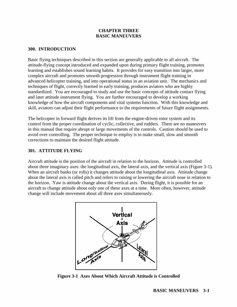
Aircraft attitude is the position of the aircraft in relation to the horizon. Attitude is controlled
about three imaginary axes: the longitudinal axis, the lateral axis, and the vertical axis (Figure 3-1).
When an aircraft banks (or rolls) it changes attitude about the longitudinal axis. Attitude change
about the lateral axis is called pitch and refers to raising or lowering the aircraft nose in relation to
the horizon. Yaw is attitude change about the vertical axis. During flight, it is possible for an
aircraft to change attitude about only one of these axes at a time. More often, however, attitude
change will include movement about all three axes simultaneously.
Figure 3-1 Axes About Which Aircraft Attitude is Controlled
CHAPTER THREE TH-57 CONTACT
3-2 BASIC MANEUVERS
The attitude of the aircraft in relation to the horizon and the power applied are the only two
elements of control in all aircraft. Proper use of these two elements of control will produce any
desired maneuver within the capability of the aircraft. Therefore, all maneuvers must be based
solidly upon attitude and power control references: attitude + power = performance!
Aircraft attitude and power are modified by the pilot in two ways: one, the time of application of
an attitude or power change; and two, the rate of change of an attitude or power adjustment.
Keeping the basic control elements and modifiers in mind, the aviator crosschecks for a running
awareness of what the aircraft is doing at the moment. Using knowledge gained from
experience, the aviator can project what the aircraft is going to do based on the power setting and
attitude being maintained. Attitude and power changes are smoothly applied to cause the aircraft
to perform the desired maneuver. The result is attitude flying.
302. ATTITUDE CONTROL AND AIRSPEED
Adjusting pitch attitude about the lateral axis of the aircraft controls airspeed. To hold a desired
airspeed, or make properly controlled changes of airspeed, the aviator must learn the aircraft
pitch attitudes resulting in acceleration, deceleration, hover, and the desired cruising airspeed.
Your flight instructor will demonstrate these various attitudes.
For a given power setting, there is a pitch attitude and airspeed that will maintain altitude. If
power is constant, an increase in airspeed (resulting from a change of pitch attitude) will cause
loss of altitude. Conversely, a reduction of airspeed with power constant will usually cause a
gain of altitude.
If power is increased while pitch attitude is held constant, airspeed will remain constant and a
climb will result. If the power setting is decreased while pitch attitude is held constant, airspeed
will remain constant and a descent will result.
303. ATTITUDE CONTROL AND COORDINATED TURNS
During coordinated flight, turns are a result of bank attitude control about the longitudinal axis of
the aircraft. To hold a desired heading, the aviator must keep the rotor disc laterally level in
relation to the horizon.
Turns are accomplished by banking (rolling) the aircraft about the longitudinal axis until the
rotor disc is tilted laterally. Rate of turn is controlled by the degree the rotor disc is tilted.
Aviators must learn to smoothly bank the aircraft to a degree of lateral tilt producing the desired
rate of turn.
Stopping a turn is accomplished by smoothly rolling the aircraft level. Roll out is started before
the desired heading is reached so the turn is stopped on the desired heading.
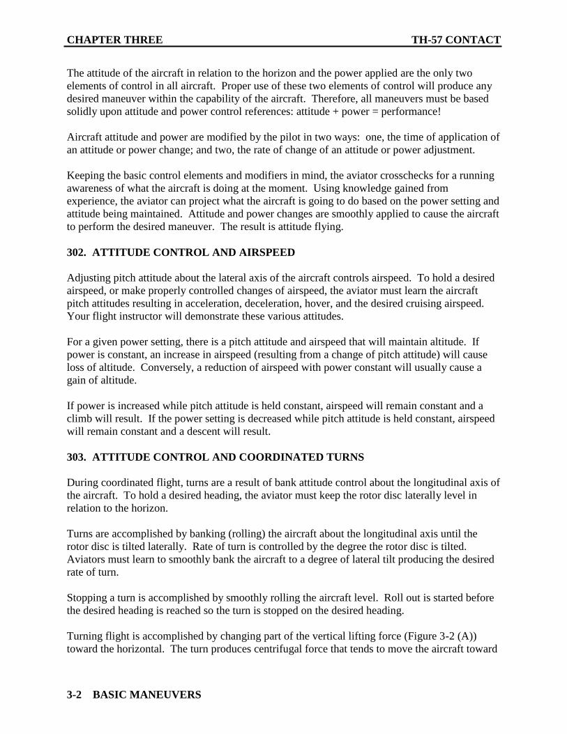
Turning flight is accomplished by changing part of the vertical lifting force (Figure 3-2 (A))
toward the horizontal. The turn produces centrifugal force that tends to move the aircraft toward
TH-57 CONTACT CHAPTER THREE
BASIC MANEUVERS 3-3
the outside of the turn (Figure 3-2 (B)). The resultant of weight and centrifugal force is outward
and downward and is greater than the weight of the aircraft in (Figure 3-2 (A)). The resultant of
weight and centrifugal force must be overcome by an addition of total lift or the aircraft will lose
altitude during a turn. (Figure 3-2 (C)), shows an increase of total lift as a result of increased
collective pitch and power. Total lift now equals the total of centrifugal force and weight, so the
aircraft will turn without losing altitude.
Figure 3-2 Loss of Vertical Lift During Turns
The resultant of weight and centrifugal force during turns produces an increased load factor on
the aircraft. Load factor is the total load imposed on an aircraft divided by the weight of the
aircraft and is expressed in G units. Load factor during a turn varies with the AOB (Figure 3-3).
Airspeed during a turn does not affect load factor. For a given bank angle, the rate of turn
decreases with an increase in airspeed resulting in no change of centrifugal force. Note for a 60º
bank, the load factor for any aircraft is 2 Gs regardless of airspeed (Figure 3-3). This means a
10,000 lbs aircraft in a 60º bank will, in effect, exert 20,000 lbs of force on the aircraft structure.
Bank angles up to 30º produce only moderate increases in load factor, which are acceptable
under most flight conditions. The load factor rises at an increasing rate for banks over 30º
(Figure 3-3), and may produce unacceptable disk loading depending upon the aircraft gross
weight and flight conditions.

CHAPTER THREE TH-57 CONTACT
3-4 BASIC MANEUVERS
Figure 3-3 Load Factors In Various Angles of Bank During Level Turns
304. POWER CONTROL AND RESULTING ALTITUDE, CLIMB, OR DESCENT
Altitude is a result of power control. To hold a desired altitude or make changes of altitude, the
aviator must apply the power settings producing the desired climb or descent when combined
with the possible combinations of attitude and airspeed. Normal power settings for hover, climb,
cruise, slow cruise, and descent must be used if precise control of altitude is desired. The pilot
must also be able to adjust power to compensate for variation in atmospheric conditions and
aircraft gross weight.
For a given attitude and airspeed, there is a power setting that will maintain altitude. If a climb is
desired with a constant attitude and airspeed, power must be increased above that required to
maintain altitude. If a descent is desired with constant attitude and airspeed, power must be
reduced below the power required for maintaining altitude.
A constant altitude is maintained by minor pitch attitude adjustments and by power adjustments
as necessary. After the altitude is stabilized and the desired airspeed is established, any deviation
from altitude will result in an airspeed change while the altitude is changing. When the altitude
is again stabilized, the airspeed will return to its previous indication provided the power is
maintained at the previous setting. If airspeed is high due to loss of altitude, the excess airspeed
may be used to return the aircraft to the desired altitude and airspeed by an upward pitch attitude
adjustment. Conversely, with a gain in altitude and an accompanying loss of airspeed, the excess
altitude may be utilized by a downward pitch attitude adjustment to return the aircraft to the
desired airspeed and altitude.

TH-57 CONTACT CHAPTER THREE
BASIC MANEUVERS 3-5
305. TURBULENCE AND WINDS
The air mass around you is, in fact, an ocean. It is in constant movement, both horizontally and
vertically. It contains currents, waves, ripples, and calm areas. When you leave the surface of
the earth, even so much as one inch, your aircraft moves with the air mass - both horizontally and
vertically. Let us assume you are in forward flight at an airspeed of 50 KIAS, and you have a
direct crosswind from your right blowing at 15 KTS. At the end of one hour, you will have
covered a distance over the ground of 50 NM, but you will have also drifted 15 NM to the left of
your course. In other words, you have been moving slightly sideways during your entire flight.
This movement is known as drifting.
You can use drifting to your advantage, however; to ensure you fly a straight ground track to
where you want to go, simply turn the nose of the aircraft slightly into the wind, as the aircraft
drifts, it moves along a ground track taking you directly to your destination (rather than 15 miles
to the left of it). This procedure is known as crabbing.
The other direction of movement the helicopter will be subject to is vertical movement. Like
waves in the ocean, the air mass moves in a vertical direction. This is caused by a number of
factors and is commonly known as turbulence. Turbulence can range from a slight rocking of
the aircraft to a jolting so severe it can cause damage to the helicopter. Because of the light
weight of a training helicopter, you will feel the effects of light turbulence nearly every time you
fly. This is quite natural, and it is absolutely no cause for concern.
The turbulence you feel will also cause slight attitude and altitude changes of the helicopter as it
moves through the air. You must take the necessary control movement to maintain altitude and
airspeed, but you should never try to “fight” turbulence, as it leads to over controlling the
aircraft.
306. CROSSWIND CORRECTIONS
Crab Correction. A crab correction is used to counteract the effect of a crosswind at altitude. It
is a condition of flight in which the nose of the helicopter is turned into the wind as necessary to
maintain a desired ground track. Anti-torque pedals are used to keep the ball in the center.
Because of the comparatively low velocities of helicopters, large drift corrections are often
necessary to compensate for crosswinds. Crab angles in excess of 20º are common. Do not try
to point the nose in the direction of travel in a crosswind. In crabbing, the aircraft is laterally
level and is in a balanced flight condition.
Wing Down, Top Rudder Crosswind Correction. After entering an approach maneuver from
pattern altitude and airspeed or cruise flight, the wing down, top rudder correction will be used to
counter crosswind conditions. When aligned into the course line on final approach, lower the
wing (rotor disk) into the wind and use the opposite (top) rudder (pedal) to maintain the nose of
the helicopter in alignment with the course line. In this condition, the aircraft is not laterally
level and is not in balanced flight condition. Point the nose directly toward intended point of
landing with pedals, and wing down as necessary to prevent drift.

CHAPTER THREE TH-57 CONTACT
3-6 BASIC MANEUVERS
307. SCAN
The Integrated Technique of Flight Instruction. Integrated flight instruction during the
Contact (B) phase teaches the student to perform flight maneuvers primarily by outside visual
references with secondary reference to flight instruments. From the first time the maneuver is
introduced, no distinction in the pilot's operation of the flight controls is made, regardless of
whether outside references or instrument indications are used for the performance of the
maneuver. Thus, the control of a helicopter by outside visual references is integrated with
instruction in the use of flight instrument indications for the same maneuver to be performed.
Control changes required to produce a given attitude by reference to the horizon in VFR flight
are identical to those used in instrument flight, and the pilot's thought processes are the same.
The basic method for presenting attitude instrument flying groups the instruments as they relate
to control function as well as aircraft performance. All maneuvers involve some degree of
motion about the lateral (pitch), longitudinal (bank/roll), and vertical (yaw) axes. Attitude
control is stressed in terms of pitch, bank, power, and trim control. Instruments are grouped as
they relate to control function and aircraft performance as follows:
1. Power Instruments
a. Torque Gauge
b. Airspeed Indicator
2. Pitch Instruments
a. Attitude Indicator
b. Altimeter
c. Airspeed Indicator
d. Vertical Speed Indicator
e. Radar Altimeter
3. Bank Instruments
a. Attitude Indicator
b. RMI
c. Turn Needle and Ball
During VFR flight, the majority of the pilot’s attention is directed outside the cockpit, as the pilot
scans for attitude in relation to the horizon in addition to traffic lookout and avoidance. Student
pilots who have been required to perform all normal flight maneuvers by outside reference as

TH-57 CONTACT CHAPTER THREE
BASIC MANEUVERS 3-7
well as reference to instruments will develop, from the start, the habit of continuously monitoring
their own and the helicopter’s performance. Consider the following example: While flying
downwind in the pattern, the horizon is maintained at a given level across the windscreen with
constant power, airspeed, altitude, and a zero climb/descent rate on the VSI. Due to a slight
increase in tension in the pilot’s arm, the cyclic control is inadvertently pulled aft. The pitch
attitude starts to deviate high and the windscreen fills with sky, the altimeter shows an increase
in altitude, airspeed bleeds off, and the VSI shows a positive rate of climb. With the integrated
scan, the pilot recognizes these changes and eases the cyclic forward to return the nose attitude to
its proper relationship to the horizon and all instrument indications back to desired parameters.

CHAPTER THREE TH-57 CONTACT
3-8 BASIC MANEUVERS
THIS PAGE INTENTIONALLY LEFT BLANK

FLIGHT TRAINING MANEUVERS – LOW WORK 4-1
CHAPTER FOUR
FLIGHT TRAINING MANEUVERS - LOW WORK
400. INTRODUCTION
This section focuses on the basic maneuvers of powered flight. These maneuvers form the
foundation of the skills required of a helicopter pilot. Follow-on stages of the syllabus will build
on these skills and require greater precision. It is imperative you develop a keen knowledge of
the procedures and an almost effortless ability to execute the maneuvers contained in this
section.
The first maneuvers discussed will become second nature to you as a helicopter pilot. After your
first SOLO flight these maneuvers will be observed and graded as “LOW WORK.” It will be
expected that the Student Military Aviator (SMA) will have a degree of skill that will provide for
safe maneuvering of the helicopter in close proximity to the ground. Remain ever vigilant when
you are at the controls at or near the ground.
401. VERTICAL TAKEOFF
Maneuver Description. A vertical takeoff enables the pilot to transition from the ground to a
hover.
Application. A vertical takeoff can be accomplished whenever the helicopter is capable of
hovering with the skids three to ten feet above the ground. The vertical takeoff is the most
common type of takeoff and should be used whenever possible. The helicopter is lifted from the
ground vertically to a height of approximately five feet measured from the skids to the ground.
Procedures
1. Trim the controls in the neutral position. Establish the hover scan and smoothly raise the
collective until light on the skids. Stabilize momentarily, trim out control pressures.
2. Smoothly raise the collective. As the helicopter leaves the ground, eliminate drift with
cyclic, and maintain a constant heading with the pedals.
3. Continue to raise the collective until reaching hover altitude. Trim out control pressures.
NOTE
In a no-wind condition, it will be necessary to displace the cyclic
to the left to overcome the anti-torque thrust from the tail rotor and
prevent the aircraft from drifting right. Because of this, the helo
will take off right skid first and land left skid first.

CHAPTER FOUR TH-57 CONTACT
4-2 FLIGHT TRAINING MANEUVERS – LOW WORK
Recommended Verbal Procedures
Takeoff check between maneuvers before lifting:
“TWIST GRIP IS FULL OPEN” = ensure the twist grip is in the full open position
“Nf and Nr are 100%” = check Nf and Nr are 100%.
“GAUGES ARE GREEN” = take the time to ensure all gauges are in the normal operation
range.
“FUEL IS _____ GALLONS” = check fuel load.
“CAUTION PANEL IS CLEAN” = check for caution lights.
“CLEAR, LEFT, RIGHT AND ABOVE” = clear the aircraft before lifting.
After clearing turn, PAC should have PNAC re-verify checks before transitioning to forward
flight.
Amplification
1. Before takeoff to a hover, check carefully for any nearby obstructions forward, rearward,
and to the sides. It is important to maintain a constant heading when departing the ground. Line
up with an object near the helicopter and one farther away and direct your attention to the front
of the aircraft.
2. Neutralize the controls, collective full down, ensure the twist grip is full open, RPM 100%,
and establish the hover scan.
3. Apply smooth, slow, upward pressure on the collective pitch until light on the skids. At
this point, trim out control pressures.
4. Once the helicopter is light on the skids, it may tend to drift and turn to the right. Hold the
collective constant at this point and stop any tendency to drift with cyclic. A slight adjustment
on the antitorque pedals will be necessary to maintain heading.
NOTE
You are in a transition to flight at this point and very susceptible to
wind gusts.
5. With your hover scan still established, smoothly apply upward pressure to the collective
until the aircraft leaves the ground. Maintain your position over the ground with cyclic and
maintain aircraft heading with antitorque pedals.
6. Upon reaching an altitude of five feet, stabilize and trim out control pressures. Use the
hover scan to obtain the level attitude and maintain it. Depress the force trim to trim the cyclic to
the level attitude. Use slight pressures against the trimmed position to maintain a stable hover.

TH-57 CONTACT CHAPTER FOUR
FLIGHT TRAINING MANEUVERS – LOW WORK 4-3
7. You are airborne, though still close to the ground. As in any type of flying, your attitude is
of primary importance, and especially since, you are so near the ground. Stop the aircraft at five
feet, clear of the ground with the collective and control your attitude with light cyclic pressures
using the horizon as your reference. Think of the whole windshield as a large attitude indicator.
If you look too close in, you will not have fine control of your attitude. Your peripheral vision
gives you depth perception and detects small movements of the aircraft. Heading control is
natural if you are looking toward the horizon, because any small heading drift is immediately
apparent.
8. Use pressures and small (very small) movements of the controls to maintain attitude,
heading, and altitude. The key with helicopters is small, precise application of pressures and
movements as necessary. Position over the ground is accomplished by making fine attitude
changes, not by gross control movements put in and then taken out. This large inputs usually
only rocks the helicopter and upsets the passengers (and your instructor!).
9. Altitude control follows the same rule - take it easy! Smooth collective pressures will get
you what you want. Use your peripheral vision for attitude reference. Close to the ground, and
with little or no groundspeed, your attitude is very important; so look away toward the horizon.
10. Do not taxi, take off, or land when an aircraft in an adjacent spot is starting or is at a very
low Nr during shutdown.
11. The pilot shall check the caution panel and instruments prior to every vertical takeoff.
Common Errors and Safety Notes
1. Failure to maintain heading.
2. Erratic ascent due to improper collective control applications.
3. Allowing helicopter to drift.
4. Allowing excessive roll during liftoff. Lateral cyclic inputs creating drift can lead to
dynamic rollover.
402. HOVER
Maneuver Description. Hovering is a maneuver in which the helicopter is maintained in nearly
motionless flight over a reference point with constant heading and altitude.
Application. Hovering is the unique flight characteristic giving the helicopter its versatility and
capability, and the maneuver used to perform the majority of helicopter missions.
CHAPTER FOUR TH-57 CONTACT
4-4 FLIGHT TRAINING MANEUVERS – LOW WORK
Procedures
1. Use pedals to maintain heading, collective to maintain altitude (five feet), and cyclic to
maintain a position over a reference point.
2. Scan “out” for heading and attitude, “down” for altitude and drift, and “in” for Nr, and
engine instruments.
Amplification and Technique
1. This maneuver requires a high degree of concentration and coordination. When hovering,
keep the helicopter over a spot by using the cyclic control stick, and maintain altitude by the use
of collective. A constant heading is kept by use of antitorque pedals. Only by the proper
coordination of all controls can you achieve successful hovering flight.
2. All control corrections should be small pressure changes rather than abrupt movements.
This is necessary to prevent over controlling which is the most common fault of the new
helicopter pilot when learning to hover. Abrupt and erratic cyclic movements will make a stable
hover impossible. A relatively constant collective (power) setting will enable smoother yaw and
cyclic corrections. A hover altitude of five feet (skid height above the ground) is utilized to
provide approximately six feet of tail stinger to ground clearance and ample tail rotor clearance
for maneuvering at hovering and taxiing altitude.
3. To maintain a hover over a point, you should look for small changes in the helicopter's
attitude and altitude. When you note these changes, make the necessary control inputs before the
helicopter starts to move from the point. To detect small variations in altitude or position, your
main area of visual attention needs to be some distance from the aircraft, using various points on
the helicopter or the tip-path plane as a reference. Looking too close or looking down leads to
over controlling. Obviously, in order to remain over a certain point, you should know where the
point is, but your attention should not be focused there.
Common Errors and Safety Notes
1. Allowing excessive nose high attitudes at low altitude.
2. Over controlling, (i.e., larger inputs, than necessary).
3. Looking through the chin bubble or “staring” rather than the “out, down, and in” scan.
4. Failure to maintain altitude.
5. Failure to maintain position over a reference point.
6. Failure to maintain heading.
7. Inadvertently rolling twist grip partially off.

TH-57 CONTACT CHAPTER FOUR
FLIGHT TRAINING MANEUVERS – LOW WORK 4-5
8. Too tense on controls.
9. Do not allow excessive nose high attitudes at low altitudes because the tail rotor may
impact the ground.
10. When first learning to hover, stress the out and down scan, vice out, down, and in.
403. VERTICAL LANDING
Maneuver Description. A vertical landing enables the pilot to land from a hover.
Application. Land the helicopter by maintaining the hover attitude and smoothly lowering the
collective until the skids come into contact with the ground and the weight is smoothly
transferred from the rotor to the skids.
Procedures
1. Smoothly lower the collective to begin a slow rate of descent.
2. Use pedals to maintain heading and cyclic to eliminate drift.
3. The rate of descent may slow or stop as the helicopter nears the ground. Continue the
descent with slight collective pressure.
4. When on the ground, smoothly lower the collective to the full down position.
NOTE
In a no-wind condition, it will be necessary to displace the cyclic
to the left to overcome the anti-torque thrust from the tail rotor and
prevent the aircraft from drifting right. Because of this, the helo
will take off right skid first and land left skid first.
Amplification and Technique
1. The pilot should stay as relaxed as possible. Make smooth and timely corrections.
2. With the helicopter stabilized in a five-foot hover and heading into the wind, begin a slow
rate of descent by applying slight downward pressure on the collective. As the aircraft descends,
adjust antitorque pedals as necessary to maintain heading and adjust the cyclic to eliminate any
drift. If you have the correct attitude, the helicopter will not drift, so constantly correct to the
proper level attitude.
a. The rate of descent will tend to slow or stop as the helicopter approaches the ground.
This tendency is due to the increased influence of ground effect with the decrease in
distance between the rotor system and the ground.
CHAPTER FOUR TH-57 CONTACT
4-6 FLIGHT TRAINING MANEUVERS – LOW WORK
b. Do not over control the cyclic at this point; maintain the “out” portion of your scan.
Continue the descent with slight downward collective pressure, and the helicopter
will move through this ground effect until ground contact is made.
c. When the skids touch the ground, lower the collective smoothly to the full down
position, and adjust cyclic as necessary to prevent any tendency to drift as the skid
gear conforms to the ground plane. Apply antitorque pedal as necessary to maintain
heading.
3. Constantly cross check all visual reference points. Hover the helicopter by maintaining a
constant attitude. Fly by PRESSURES on the controls and not a movement of the controls. A
series of small corrections are better than one large correction. Do not attempt to lower the
collective rapidly after the skids are on the ground. The landing is not complete until the
collective is fully down.
Common Errors and Safety Notes
1. Over controlling collective pitch control.
2. Improper use of cyclic control, allowing aircraft to slide over the ground after contact.
3. Improper use of antitorque pedals, allowing the nose of the aircraft to yaw.
4. Avoid landing the helicopter with any drift. Lateral drift on touchdown can lead to
dynamic rollover. Rearward drift can result in tail rotor strike. Forward drift is not desired.
5. Failure to maintain the hover scan (i.e., allowing scan to come in too close to the aircraft
and staring through the chin bubble).
6. “Feeling” for the ground with collective. Remember, every landing should be a surprise.
7. Anticipating ground contact and lowering collective too quickly, resulting in a firm
landing. Remember, if you have done it right, you will barely feel it.
404. TURN ON THE SPOT/CLEARING TURN
Maneuver Description. A turn on the spot is a maneuver in which the helicopter is rotated
about its vertical axis while maintaining a position over a reference point.
Application. Turns on the spot and clearing turns enable the pilot to clear the area prior to each
takeoff, to change the direction of taxi, and to improve his/her control coordination.
Procedures
1. From a hover, begin a slow turn by displacing the appropriate pedal.

TH-57 CONTACT CHAPTER FOUR
FLIGHT TRAINING MANEUVERS – LOW WORK 4-7
2. As the helicopter turns, adjust the cyclic as necessary to remain over the reference point
and pedals as necessary to control the rate of turn.
3. Stop the turn on the desired new heading.
Crew Resource Management
PAC initiates aircraft clearing procedure (Situational Awareness)
Amplification and Technique
In a hover, you are fully airborne, five feet above ground; therefore, completely under the
influence of the wind, gusts, and turbulence associated with flight. For instance, if the wind
velocity is 15 KTS on your nose and you wish to remain over a selected spot, you must tilt the
rotor disc into the wind enough to equalize the drag on the helicopter; you are flying forward at
15 KTS relative to the wind. If you turn the helicopter's tail into the wind, you must fly
backwards at 15 KTS relative to the wind to remain over your selected spot. The turn is
accomplished with pedals; however, the cyclic needs some explanation first. Simply stated, the
problem is to keep the cyclic into the wind enough to balance the thrust of the rotor against the
force of the wind. (Figures 4-1 through 4-3) show the cyclic roughly parallels the lift vector of
the rotor; therefore, a rule-of-thumb is that the resultant lift of your main rotor could be
considered an extension of the cyclic grip which you constantly hold in your right hand, so it is
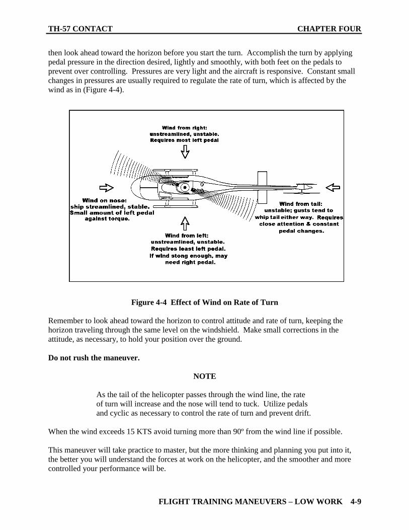
good constant reference. Now, as the aircraft turns through an through an arc, you can see the
tilt of the cyclic must turn through an arc also, at the same rate the aircraft turns, but opposite
direction. From above, it would look something like (Figure 4-4).
Figure 4-1 Effect of Wind on The Lift Vectors

CHAPTER FOUR TH-57 CONTACT
4-8 FLIGHT TRAINING MANEUVERS – LOW WORK
Figure 4-2 Effect of Wind on The Lift Vectors
Figure 4-3 Effect of Wind on The Lift Vectors
It will take some practice to master this maneuver. The important thing to remember is the
helicopter’s attitude must be kept constant and level. You will notice, to remain stationary over a
point, the attitude of the helicopter is nearly the same regardless of the wind’s direction. The
rotor disc is tilted into the wind but the fuselage is hanging nearly level. From your point of
view, the horizon should cut through the windshield at approximately the same level all the way
around in a hovering turn.
Pedal control in a hovering turn is relatively simple. Direction of turn and rate of turn are
controlled directly by the pedals. A good technique is to clear the area visually for your turn,
TH-57 CONTACT CHAPTER FOUR
FLIGHT TRAINING MANEUVERS – LOW WORK 4-9
then look ahead toward the horizon before you start the turn. Accomplish the turn by applying
pedal pressure in the direction desired, lightly and smoothly, with both feet on the pedals to
prevent over controlling. Pressures are very light and the aircraft is responsive. Constant small
changes in pressures are usually required to regulate the rate of turn, which is affected by the
wind as in (Figure 4-4).
Figure 4-4 Effect of Wind on Rate of Turn
Remember to look ahead toward the horizon to control attitude and rate of turn, keeping the
horizon traveling through the same level on the windshield. Make small corrections in the
attitude, as necessary, to hold your position over the ground.
Do not rush the maneuver.
NOTE
As the tail of the helicopter passes through the wind line, the rate
of turn will increase and the nose will tend to tuck. Utilize pedals
and cyclic as necessary to control the rate of turn and prevent drift.
When the wind exceeds 15 KTS avoid turning more than 90º from the wind line if possible.
This maneuver will take practice to master, but the more thinking and planning you put into it,
the better you will understand the forces at work on the helicopter, and the smoother and more
controlled your performance will be.

CHAPTER FOUR TH-57 CONTACT
4-10 FLIGHT TRAINING MANEUVERS – LOW WORK
To make a 45º clearing turn, stabilize the helicopter completely after finishing either a 45º turn
on the spot left and right of course line. Clear yourself of other traffic. A full 360º clearing turn
is performed in the same manner as the 45º turn, with additional emphasis placed on maintaining
a constant five-foot hover and consistent rate of turn. Utilize the normal hover scan.
Common Errors and Safety Notes
1. Allowing altitude to change.
2. Drifting.
3. Excessive rate of turn.
4. Maximum winds for 360º turns on the spot are 15 KTS from any quadrant. However, high
density altitude significantly influences demand on the tail rotor as a result of increased demand
on the main rotor. Consult the NATOPS Manual for current wind limitations.
5. A common error is to rotate about the pilot’s seat instead of rotating about the aircraft's
vertical axis.
405. HOVER TAXI/AIR TAXI
Maneuver Description. Hover taxi is used to describe helicopter movement conducted above the
surface and in ground effect at airspeeds less than approximately 20 KTS. The actual height may
vary, and some helicopters may require hover taxi above 25 feet AGL to reduce ground effect
turbulence or provide clearance for cargo sling loads. Air taxi is used to describe helicopter
movement conducted above the surface but normally not above 100 feet AGL. The aircraft may
proceed either via hover taxi or flight at speeds more than 20 KTS. The pilot is solely responsible
for selecting a safe airspeed/altitude for the operation being conducted.
Application. Hover taxiing is utilized extensively to maneuver the aircraft from one position to
another.
Procedures
1. From a hover, displace the cyclic in the desired direction of movement.
2. Utilize pedals to maintain heading, collective to maintain altitude, and the cyclic to
maintain the desired rate of movement.
3. Hover taxiing shall be conducted at a reasonable rate of speed such that a safe landing can
be accomplished in the event of a loss of power.
Crew Resource Management
1. PAC initiates aircraft clearing procedure. (Situational Awareness)

TH-57 CONTACT CHAPTER FOUR
FLIGHT TRAINING MANEUVERS – LOW WORK 4-11
2. PAC notifies crewmembers of the direction of travel. (Communication)
Figure 4-5 Taxi Signals
Amplification and Technique
1. From a hover, apply sufficient cyclic to establish a slow rate of movement over the ground
in the desired direction of movement. Use antitorque pedals to maintain heading, collective to
maintain altitude, and cyclic to maintain the desired direction of movement.
2. If you have a crosswind, apply lateral cyclic into the wind to maintain ground track.
3. A combination of collective pitch and cyclic governs starting, stopping, and rate of speed
while taxiing.
4. Standard taxi signals are depicted in (Figure 4-5).

CHAPTER FOUR TH-57 CONTACT
4-12 FLIGHT TRAINING MANEUVERS – LOW WORK
5. Taxi signals are advisory only, except for “HOLD” which is mandatory. The pilot is
responsible for the safe operation of the helicopter.
6. Hover taxi speeds within the line environment should be no faster than a man can walk.
Common Errors and Safety Notes
1. If the wind across the deck exceeds 15 KTS, turns more than 90º from the wind line should
be avoided if possible. Maximum sideward airspeed is 25 KTS and 15 KTS is the maximum
airspeed for rearward flight. However, the airspeed indicator is inaccurate in sideward and
rearward flight and airspeed must, therefore, be estimated based on the combined effect of
groundspeed and winds.
2. The minimum distance between helicopters while air taxiing is 100 feet, unless under the
direction of a taxi director or engaged in formation taxi on a pre-briefed formation hop.
406. SQUARE PATTERNS
Maneuver Description. Squares are precision maneuvers performed at hover altitude utilizing
references outside the cockpit.
Application. These maneuvers improve flight control coordination and the pilot's ability to
perform low work operations.
Procedures
1. Constant-Heading Square
a. From the starting position, move laterally in either direction along the side of the
square.
b. When reaching the corner, stop, stabilize the hover, and continue in the new direction.
maintain a constant heading with pedals.
c. When moving forward or rearward, the side of the square should be under the aircraft
to provide the pilot with a visual reference.
d. When moving laterally, the heading should be perpendicular to the side of the square.
2. Parallel-Heading Square
a. From the starting position, move forward and place the side of the square under the
helicopter. Turn 90º to the right to place the square beneath the longitudinal axis and
begin a forward air taxi.
b. Anticipate a hover at the corner. Stop with the next side abeam the pilot's shoulder.

TH-57 CONTACT CHAPTER FOUR
FLIGHT TRAINING MANEUVERS – LOW WORK 4-13
c. Execute a 90º left turn on the spot to place the new side beneath the helicopter.
Stabilize the hover, and continue the air taxi. Continue until reaching the middle of
the downwind side. Turn 90 º and taxi rearward to the starting position.
3. Perpendicular-Heading Square
a. From the starting position, begin slow lateral movement in either direction along the
side of the square, maintaining the heading perpendicular to the square with pedals.
b. As the helicopter reaches the corner, coordinate cyclic and rudder to turn to a heading
perpendicular to the next side. Do not stop the lateral motion.
c. Continue until reaching the starting position.
Amplification and Technique
There are three types of square patterns: the constant-heading square, the parallel-heading
square, and the perpendicular-heading square. All square patterns will be performed at hover
altitude. All square patterns will be started in the middle of the downwind side with the heading
of the helicopter perpendicular to the side of the square. The distance from the square should be
sufficient to scan the side of the square over the instrument panel.
1. Constant-Heading Square - From the starting point, commence a slow controlled slide
(left or right) by displacing the cyclic in the desired direction. Maintain a constant distance from
the square. Hover momentarily at the corner of the square, and commence a slow forward taxi
with the side of the square under the helicopter to provide a visual reference. Stop the helicopter
with sufficient distance to scan the next side of the square over the instrument panel. Hover
momentarily, and then commence a slide as before while maintaining constant-heading and
altitude until the next vertical side of the square is under the helicopter. Hover momentarily and
then commence a rearward taxi with the side of the square under the helicopter. Stop the
helicopter with sufficient distance to scan the starting side of the square over the instrument
panel. Hover momentarily, and then commence a lateral taxi back to the starting point.
2. Parallel-Heading Square - The helicopter is taxied forward from the starting position until
the downwind side of the square is passing through the pilot’s shoulders. Hover momentarily,
and then execute a right turn on the spot to place the side of the square under the centerline of the
helicopter. Taxi forward to the corner and turn left to parallel the next side while placing the
side of the square under the centerline of the helicopter. Follow this procedure all the way
around the square. When back to the original starting position, make a 90º turn and air taxi
backwards to the starting point.
3. Perpendicular-Heading Square - From the starting point start a slow slide to the right or
left while maintaining a constant distance from the square and heading perpendicular to the side
of the square. As the aircraft approaches the corner of the square, coordinate pedals and cyclic to
commence a turnabout the nose to arrive at the next side with a heading perpendicular to the side
of the square. Do not stop the lateral movement. The pilot shall keep the same distance from the

CHAPTER FOUR TH-57 CONTACT
4-14 FLIGHT TRAINING MANEUVERS – LOW WORK
side of the square. Maintain a constant rate of lateral movement. Follow this procedure all the
way around the square back to the starting point.
4. Be aware of the common tendency to get low at the corners during the turn.
5. As the tail of the helicopter passes through the wind line, the nose will tend to tuck and the
rate of turn will tend to increase. BE ALERT!
6. DO NOT RUSH! Square patterns are precision maneuvers. Make small, smooth, and
deliberate corrections. SCAN!
7. Parallel and perpendicular heading squares shall not be performed in winds exceeding 15
KTS.
8. Use peripheral vision to maintain position on the square and continue to scan.
Common Errors and Safety Notes
1. Taxiing too fast, rushing maneuver.
2. Failure to maintain a constant position relative to square pattern.
3. Failure to maintain position over corners during turns to parallel the next side while
performing parallel heading squares.
4. Failure to maintain altitude.
5. Failure to maintain hover scan (i.e., scanning in close, staring through the chin bubble, or
fixating on the box).
407. TRANSITION TO FORWARD FLIGHT
Maneuver description. The transition to forward flight enables the pilot to gain airspeed and
altitude from a hover.
Application. This maneuver enables the pilot to perform a safe transition from a hover to
forward flight while minimizing time spent in the caution area of the height velocity diagram.
Refer to the TH-57 NATOPS Part I, Chapter 4, Height Velocity Diagram.
Procedures
1. From a stable hover, begin forward motion.
2. Add collective if necessary to prevent settling as the helicopter leaves its ground cushion.
Maintain helicopter heading aligned with the direction of travel.

TH-57 CONTACT CHAPTER FOUR
FLIGHT TRAINING MANEUVERS – LOW WORK 4-15
3. Continue to accelerate while maintaining the wing down, top rudder crosswind correction.
Arrive at 20 feet AGL with 40 KIAS.
4. Passing through 50 feet and 65 KTS adjust the nose to the 70 KTS climbing attitude,
transition to balanced flight, and climb at 500 to 700 feet per minute. Maintain the 70 KTS
climbing attitude in balanced flight.
5. Fifty feet below the desired altitude, adjust the nose to the cruise attitude. Maintain climb
power. Approaching the desired airspeed, adjust the collective to level-off at the desired altitude.
Maintain balanced flight.
Crew Resource Management
1. PAC requests takeoff from Tower prior to Hold Short. (Communication)
2. PAC directs PNAC to check fuel, power, note time, and turn transponder to ALT.
(Situational Awareness)
3. PAC reports “Caution panel clear, gauges green” on ICS prior to forward flight.
(Situational Awareness)
Amplification and Techniques
1. In order to accomplish the maneuver, sufficient power to hover must be available, and no
obstacles can be in the flight path to restrict a normal climb out.
2. A normal takeoff is executed from a five-foot hover. If at an OLF, make a clearing turn to
ensure that there are no aircraft near enough to prevent a safe takeoff. Check and report the
gauges green and caution lights out. Select two or more points along the intended takeoff path.
These guide points will be used in maintaining the desired ground track. When taking off,
proceed straight down the courseline. Do not angle or allow the helicopter to drift laterally. Be
alert for other aircraft!
3. To start moving forward, apply forward pressure on the cyclic. Do not apply too much
cyclic, as this will result in a nose-low attitude. With the nose too low, the helicopter will gain
airspeed rapidly and tend to descend due to loss of vertical lift. When you move forward out of
ground effect with calm or light wind conditions, you may have to increase collective pitch to
maintain five feet until you reach effective translational lift. A slight settling of the helicopter
occurs as you begin to move forward because a portion of the power that has been producing lift
is now being used for thrust. To compensate, small up-pressure on the collective is necessary to
hold your altitude.
4. As the helicopter passes through translational lift (10 to15 KTS), you will feel a
considerable increase in lift and the helicopter will tend to yaw left as the main and tail rotors
move into translational lift. The nose will tend to pitch up slightly due to dissymmetry of lift.
Just before reaching this condition, you will be alerted to it by a moderate vibration or shudder

CHAPTER FOUR TH-57 CONTACT
4-16 FLIGHT TRAINING MANEUVERS – LOW WORK
throughout the helicopter caused by transverse flow effect. (These terms are explained in your
aero text.)
5. At this point, apply additional forward cyclic to overcome the tendency of the nose to pitch
up (blowback).
6. Establish a climb with the first transition checkpoint at 20 feet AGL and 40 KIAS. Do not
become excessively nose low as this will reduce the chances for a successful autorotation should
engine failure occur on takeoff.
7. For wind corrections, the “wing down, top rudder” correction still applies to keep the
helicopter moving straight down the courseline and to prevent drift.
8. Passing through 65 KTS and 50 feet AGL adjust the nose to the 70 KTS climbing attitude
and adjust collective to establish and maintain a 500 to 700 feet per minute climb. Transition
from the wing down, top rudder crosswind correction to balanced flight. If necessary, utilize a
crab angle to maintain a ground track straight down the courseline. Downwind turns shall
normally be executed no earlier than 70 KIAS and 200 feet AGL.
9. Fifty feet prior to level-off altitude, adjust the nose to either the 70 or 100 KTS cruise
attitude. If 100 KTS is desired, maintain climb power. Approaching 100 KTS, readjust collective
to stabilize at altitude. If 70 KTS is desired, then only a slight readjustment of collective is
required.
Common Errors and Safety Notes
1. The pilot shall ensure there is sufficient distance to accomplish a safe, normal takeoff.
2. Rushing the initial takeoff.
3. Unnecessary increase of collective to start takeoff.
4. Poor heading control.
5. Excessive nose-low attitude on takeoff.
6. Forgetting to check the caution panel and gauges prior to transition to forward flight.
7. Starting the maneuver by increasing collective vice forward cyclic.
NOTE
For instrument takeoff climb out parameters, refer to the TH-57
Instrument Flight Training Instruction.

TH-57 CONTACT CHAPTER FOUR
FLIGHT TRAINING MANEUVERS – LOW WORK 4-17
408. MAXIMUM LOAD TAKEOFF (SIMULATED)
Maneuver Description. The maximum load takeoff utilizes ground cushion and translational
lift to become airborne when high gross weight or high-density altitude conditions make a
vertical takeoff impossible.
Application. The maximum load takeoff is designed to practice the low-hover transition into
forward flight when it is necessary to become airborne when operating at maximum gross weight
or a high density altitude where a vertical takeoff would not be possible.
Procedures
1. Hover into the courseline at five feet, check and state the power (ng) required to maintain a
hover.
2. Make a clearing turn and land.
3. Raise the collective until the aircraft is just clear of the ground and stabilize momentarily.
4. Begin slow forward movement, remaining in ground effect.
5. Add power as necessary to prevent settling. Maintain heading with pedals.
6. When passing through translational lift, adjust the cyclic to prevent excessive climb.
7. This maneuver is complete when 40 KIAS is attained at an altitude no higher than 20 feet
AGL then announce “maneuver complete.”
Amplification and Technique
1. Hover into the wind at five feet and check the power (Ng) required to maintain a hover.
The maximum power permitted for this maneuver simulating maximum power available for
takeoff will be the power required to hover.
2. Make a clearing turn and land.
3. Check gauges and caution lights, establish hover scan.
4. Raise the collective until the aircraft is just clear of the ground and stabilize momentarily.
Power required should not yet be equal to maximum power “available.”
5. Begin slow forward movement with very slight forward cyclic inputs utilizing ground
effect to stay airborne. Use remaining power “available” as necessary to avoid settling back to
the ground. Settling will normally occur and should be anticipated.
6. Do not exceed maximum power “available.” Increase power smoothly to maximum power
“available” and coordinate forward cyclic to remain airborne in ground effect while accelerating.

CHAPTER FOUR TH-57 CONTACT
4-18 FLIGHT TRAINING MANEUVERS – LOW WORK
DO NOT RUSH INTO FORWARD FLIGHT. Maintain heading with the pedals.
7. When passing through translational lift, adjust the cyclic to prevent an undesired climb and
continue with the transition to forward flight remaining lower than normal and in ground effect.
8. The maneuver is considered complete when 40 KIAS is attained at an altitude no higher
than 20 feet AGL.
Common Errors and Safety Notes
1. The rate of cyclic application must be slow. Too fast an application will cause the
helicopter to settle to the ground.
2. Do not allow the helicopter to settle back to the ground after forward movement has begun.
3. The pilot shall maintain a constant heading during the takeoff. Maintaining directional
control prevents sideslipping, which can lead to dynamic rollover while in ground contact.
4. Not accelerating through translational lift will result in marginal climb/acceleration
performance.
409. NO HOVER TAKEOFF
Maneuver Description. The no hover takeoff enables the pilot to safely transition from the
ground to forward flight while avoiding the dangers of white out/brown out conditions caused by
loose snow or soil/sand.
Application. The no hover takeoff is an alternative to the vertical takeoff and normal transition
to forward flight. It is employed during operations when takeoff visibility would be reduced due
to blowing snow, soil/sand, or other particulate matter stirred up by the rotor wash generated by
hover flight.
Procedures
1. In a hover, make a clearing turn and land.
2. Trim the controls in the neutral position. Establish a hover scan and smoothly raise the
collective in a continuous pull not to exceed 85% torque.
3. As the helicopter leaves the ground, apply forward cyclic to begin forward motion.
Maintain heading with pedals.
4. Maintain an outside visual scan and continue to accelerate, gaining airspeed to reach
translational lift as soon as possible while maintaining a safe ground clearance.
5. At 40 KIAS, adjust power and intercept normal forward flight parameters.

TH-57 CONTACT CHAPTER FOUR
FLIGHT TRAINING MANEUVERS – LOW WORK 4-19
Amplification and Technique
1. Check for any nearby obstructions prior to starting the maneuver.
2. Neutralize the controls and check collective full down. Ensure twist grip is full open, Nr at
100%, and then establish a hover scan.
3. Apply smooth, upward pressure on the collective. Do not hesitate or stop once collective
pull has started until reaching maximum power “available” as rotor wash will quickly begin
lifting debris into the air.
4. As the helicopter leaves the ground, apply simultaneous forward cyclic and left pedal to
transition into translational lift. This ensures whiteout/brownout conditions remain behind the
aircraft. Maintain heading with pedals. The rate of forward cyclic application must be slow to
prevent an excessive nose low attitude and aircraft settling when in close proximity to the
ground.
5. Maintain power required until reaching 40 KIAS, then reduce power and proceed with
normal transition to forward flight parameters.
6. The maneuver is complete when reaching 40 KIAS.
Common Errors and Safety Notes
1. Failure to maintain heading.
2. Failure to maintain a positive and constant collective pull until reaching torque required,
not to exceed 85%.
3. Failure to apply sufficient forward cyclic to stay ahead of the rotor wash.
410. NORMAL CRUISE
Maneuver Description. Normal cruise is commonly used to fly the aircraft from one point to
another Normal cruise airspeed is 100 KTS.
Application. Normal cruise shall be conducted at a safe altitude and as dictated by weather,
aircraft configuration and weight, terrain and obstacles, and mission requirements. Power and
attitude should be adjusted to attain desired cruise airspeed. Normal cruise is determined from
information in Part XI of the NATOPS Manual. Slow cruise airspeed is 70 KTS.
Procedures
1. Set the proper cruise attitude with cyclic and adjust collective as necessary to maintain
altitude and airspeed.

CHAPTER FOUR TH-57 CONTACT
4-20 FLIGHT TRAINING MANEUVERS – LOW WORK
2. Maintain balanced flight with pedals.
Amplification and Technique
1. To establish normal cruise, adjust the nose to the cruise attitude with cyclic to maintain
airspeed, and adjust the collective to maintain altitude. Torque for normal cruise (100 KIAS) is
typically 70-75% indicated.
2. The attitude and VSI are the primary scan items you will utilize to maintain 100 KTS
normal cruise and desired altitude.
3. Maintain balanced flight with pedals and trim.
Common Errors
1. Failure to maintain the cruise attitude.
2. Failure to maintain altitude.
3. Weak scan resulting in large changes in altitude.
4. Failure to maintain balanced flight.
411. CLIMBS
Maneuver description. Climbs are coordinated maneuvers designed to increase altitude.
Application. Climbs are normally accomplished when it is desired to climb from an established
altitude to a selected higher altitude. There are two types of climbs: normal climb and cruise
climb.
Procedures
1. Normal Climb
a. Transition to the 70 KTS climb attitude.
b. At 70 KTS, adjust collective as necessary to establish a 500 to 700 feet per minute
climb, maintaining balanced flight.
c. Fifty feet prior to the desired altitude, lower the nose to the cruise attitude. Maintain
climb power.
d. Upon reaching cruise airspeed, adjust collective to level-off at the desired altitude and
maintain balanced flight.

TH-57 CONTACT CHAPTER FOUR
FLIGHT TRAINING MANEUVERS – LOW WORK 4-21
2. Cruise Climb
a. Add power to establish a 500 to 700 feet per minute climb while maintaining cruise
airspeed.
b. Fifty feet prior to the desired altitude, reduce power to maintain altitude. Maintain
balanced flight.
Amplification and Technique
1. Normal climb. To establish a normal climb from cruise flight, clear the area for other
aircraft, then raise the nose slightly and assume the 70 KTS climbing attitude. Upon reaching 70
KTS, increase collective to establish a 500 to 700 feet t per minute climb. Simultaneously apply
left pedal to counteract torque. Fifty feet prior to the desired altitude, lower the nose to the cruise
attitude. Maintain climb power. Upon reaching the desired cruise airspeed, reduce the collective
and simultaneously apply right pedal to compensate for reduced torque.
2. Cruise climb. To establish a cruise climb from cruise flight, clear the area for other aircraft,
increase collective, simultaneously adding left rudder to counteract increased torque. Ensure
torque limitations are not exceeded. Maintain the cruise attitude while climbing at 100 KTS.
Fifty feet prior to the desired altitude, lower the collective, simultaneously adding right pedal to
counteract reduced torque. Adjust the nose attitude to maintain straight and level flight.
Common Errors
1. Failure to maintain airspeed (attitude).
2. Failure to maintain climb power.
3. Failure to make proper level-off.
4. Improper antitorque pedal coordination.
5. Climbing above desired level-off altitude.
6. Failure to scan torque.
412. NORMAL DESCENTS
Maneuver Description. Descents are coordinated maneuvers designed to decrease altitude
during flight.
Application. Descents are normally accomplished when it is desired to descend from an
established altitude to a selected lower altitude. A descent is performed at normal cruise
airspeed, and collective pitch control is adjusted as required for a desired rate of descent.

CHAPTER FOUR TH-57 CONTACT
4-22 FLIGHT TRAINING MANEUVERS – LOW WORK
Procedures
1. Lower the collective to establish a 700 to 1000 feet per minute rate of descent while
maintaining the cruise attitude. Maintain balanced flight.
2. Fifty feet above the desired altitude, increase the collective sufficiently to level-off at the
desired altitude while maintaining cruise airspeed and balanced flight.
Amplification and Technique
1. To initiate a descent from cruise flight, maintain the cruise attitude and lower the collective
to establish a 700 to 1000 feet per minute rate of descent.
2. Maintain balanced flight with antitorque pedals by simultaneously adding right rudder to
compensate for reduced torque.
3. Approximately 50 feet prior to reaching the desired cruising altitude, increase collective
while simultaneously applying left pedal to compensate for increased torque.
Common Errors
1. Failure to maintain airspeed.
2. Descending below level-off altitude.
3. Improper antitorque pedal coordination.
413. LEVEL SPEED CHANGE/CONTACT STAGE
Maneuver Description. A level speed change enables the pilot to transition from one airspeed
to another while maintaining a constant altitude and heading.
Application. Level speed changes are frequently utilized to set up for an approach or to
transition to another airspeed.
Procedures
1. Establish a 100 KTS cruise flight at a given altitude at or above 500 feet.
2. Coordinate a reduction in power with aft cyclic to slow the aircraft to 70 KTS, maintaining
altitude, heading and balanced flight. Stabilize momentarily at 70 KTS.
3. Coordinate an increase in power with forward cyclic to accelerate back to 100 KTS,
maintaining altitude, heading, and balanced flight.
TH-57 CONTACT CHAPTER FOUR
FLIGHT TRAINING MANEUVERS – LOW WORK 4-23
Amplification
1. This maneuver can be executed from any airspeed, but it typically is done from 100 KTS
cruise flight.
2. To slow to 70 KTS, coordinate a reduction in collective power with aft cyclic to slow the
aircraft. Simultaneously, add right pedal to counteract reduced torque and scan the VSI to
maintain altitude.
3. Approaching 70 KTS indicated airspeed; readjust the nose to the 70 KTS level attitude. At
the same time increase collective slightly to maintain altitude and add left pedal to compensate
for increased torque and scan the VSI to maintain altitude.
4. To accelerate back to cruise flight, coordinate an increase in collective power with forward
cyclic. Simultaneously add left pedal to counteract increased torque. Maintain altitude, heading,
and balanced flight.
5. To expedite this maneuver understand and utilize expected torque values. You will begin
the maneuver at 100 KIAS (70-75% Q). Remember this value. Slowing to 70 KIAS will require
a reduction in torque to a value below the torque required to maintain 70 KIAS (50-55% Q). The
rate of reduction is technique: the faster and greater the torque reduction, the faster you will
decelerate; you will also need greater coordination with yaw control. To stabilize at 70 KIAS
bring the torque to 50-55%. Remember this value, you will use it in the pattern at the OLF. To
accelerate to 100 KIAS; you will need to bring the torque to a value slightly higher than your
initial cruise torque setting. Again, the rate and magnitude of torque change will be technique.
When you have reached 100 KIAS, reduce the torque to your cruise torque value. This
maneuver is to be executed smoothly with deliberate changes in power and airspeed.
Common Errors
1. Improper antitorque pedal coordination.
2. Failure to maintain altitude.
3. Rushing the maneuver.
4. Failure to maintain balanced flight.
5. Failure to anticipate 70 KTS and to adjust the nose to the 70 KT level attitude.
6. Slow scan; failure to scan necessary instruments.
7. Using large attitude changes instead of small corrections.

CHAPTER FOUR TH-57 CONTACT
4-24 FLIGHT TRAINING MANEUVERS – LOW WORK
414. TURN PATTERN/CONTACT STAGE
Maneuver Description. The Contact Stage turn pattern develops the pilot’s skill to visually
acquire a desired angle of bank and turn while simultaneously maintaining airspeed and altitude.
Application. The turn pattern is a skills development maneuver that develops the pilot’s
awareness of visual cues that indicate the angle of bank, the pitch attitude required to maintain
airspeed, and the subtle power changes required to maintain altitude at different angles of bank.
Procedures
1. Establish 100 KTS or 70 KIAS flight at a given altitude, at or above 500 feet.
2. Initiate a turn in either direction utilizing 15° AOB for 90° of heading change.
Approaching 90° of turn, reverse the turn at 15° AOB to the original heading.
3. After the second 15° AOB turn, reverse the turn and roll into a 30° AOB turn for 180° of
heading change. Approaching 180° of turn, reverse the turn at 30° AOB to the original heading.
4. After the second 30° AOB turn, reverse the turn and roll into a 45° AOB turn for 360° of
heading change. Approaching 360° of turn, reverse the turn at 45° AOB to the original heading.
5. After the second 45° AOB turn, roll wings level on heading, altitude, and airspeed.
Amplification and Technique
1. The reversals will begin at a point prior to the reversal heading.
2. Little or no power change is required for the 15º AOB turn, but some additional power may
be required for the 30º AOB turn, and usually a definite power increase will be required to
maintain altitude for the 45º AOB turn.
Common Errors and Safety Notes
1. Failure to maintain the proper AOB due to a breakdown in scan and trim techniques.
2. Failure to maintain altitude and airspeed because of a need for additional power in the
steeper AOB turns.
3. Ballooning during reversal due to poor power management/scan breakdown.
4. Failure to scan VSI for climb/descent trends. Watch tendency to pull the nose up or allow
it to fall during reversals.
5. Failure to keep ball centered.

TH-57 CONTACT CHAPTER FOUR
FLIGHT TRAINING MANEUVERS – LOW WORK 4-25
415. NORMAL APPROACH
Maneuver Description. The normal approach enables the pilot to transition from cruise flight
to a hover over a specific point.
Application. The normal approach is a transition maneuver which allows the helicopter to
arrive simultaneously at zero groundspeed and hover altitude over a preselected spot with a
maximum margin of safety. It is designed to minimize the amount of time spent in a flight
envelope where the probability of a safe autorotation is questionable.
Procedures
1. Maintain 500 feet AGL, 70 KTS on Downwind.
2. At the 180º position, lower the collective and begin a descending, decelerating turn towards
the courseline. Maintain balanced flight.
3. Arrive at The 90º position with 300 feet AGL and 60 KTS.
4. Intercept the courseline by 150 feet AGL, with 50 KTS, and sufficient straightaway (600 to
800 feet) to intercept the glideslope. Establish crosswind corrections as necessary.
5. At 150 feet AGL, set the appropriate decel attitude and adjust the collective to maintain a
constant glideslope between 10 and 20 degrees.
6. Arrive over the spot at hover altitude, hover power, and zero groundspeed simultaneously.
Recommended Verbal Procedures
Normal Approach (at the abeam position):
“POWER” = reduce power to begin a 500-700 fpm descent.
“PEDAL” = apply right pedal to keep the aircraft in trim.
“PAUSE” = pause momentarily to check the aircraft in a 500-700 fpm descent.
“TRIM” = use pedals to center the ball and cyclic and trim to ensure aircraft is in balanced
flight.
“TURN” = clear the aircraft left and right, and then begin the descending, decelerating turn.
Crew Resource Management
1. PAC notifies aircrew of approach and landing intentions. (Communication)
2. PAC requests landing clearance in a timely manner, as required. (Situational Awareness)

CHAPTER FOUR TH-57 CONTACT
4-26 FLIGHT TRAINING MANEUVERS – LOW WORK
3. PAC ensures Landing Checklist is completed prior to pattern entry. (Situational
Awareness)
Amplification and Technique
1. It is important the helicopter be properly established at the 180º position directly abeam the
intended point of landing at 70 KTS and 500 feet AGL. Begin a descending decelerating turn
with collective and maintain balanced flight (i.e., power, pedal, pause). 25 to 30% torque makes
for nearly a 500 fpm rate of descent. Adjust the angle of bank and rate of descent to arrive at the
90º position with 300 feet AGL and 60 KTS. At the 90º position, the glideslope and rate of
closure visual cues should be acquired.
2. A normal approach intercepts the courseline/glideslope between 150 and 200 feet AGL,
50 KTS, and 600 to 800 feet of straightaway. On final, set the appropriate deceleration attitude
and adjust the collective to maintain constant glideslope between 10 and 20 degrees. Upon
intercepting the courseline, establish a “wing down, top rudder” crosswind correction as required.
3. During the last portion of the approach, the aircraft may tend to descend below the desired
glide slope. If this occurs, an increase in collective is required to prevent landing short. As
power is increased, you will need to begin applying left pedal against the increased torque.
4. As the helicopter transitions to a hover, slight forward cyclic may be necessary to
counteract pendulum effect (un-commanded nose-up tendency). Terminate the approach in a
level attitude with no forward motion, five feet above the intended point of landing.
5. The amount of deceleration required to establish the helicopter on the glideslope will vary
from day to day depending upon wind, temperature, and gross weight of the aircraft. The
airspeed required to maintain the proper rate of closure will vary with wind velocity. However,
for a given set of conditions, the deceleration attitude remains essentially constant. Do not over
control the cyclic. The object is to always fly the “same” approach profile by compensating for
changing conditions. Your instructor will demonstrate the sight picture. Take note of relative
position of the horizon and the instrument panel. The best way to visualize the proper sight
picture is to compare outside reference points to fixed points on the windscreen and/or the
instrument panel. The actual sight picture will depend on your sitting height but you will quickly
learn what the correct sight picture is for you. The sight picture will not be accurate if the
helicopter is not in the proper attitude, and the result will be an improper approach profile.

TH-57 CONTACT CHAPTER FOUR
FLIGHT TRAINING MANEUVERS – LOW WORK 4-27
Figure 4-6 Normal Approach
6. The pilot must anticipate the glideslope and simultaneously reduce the collective, add right
rudder, and raise the nose smoothly. An excessively slow collective reduction will result in the
helicopter getting steep on the glideslope. Once the helicopter is established on the glideslope,
use power to control the glideslope.
7. On final, a crosswind correction may be necessary. The proper scan to maintain the
glideslope on final should be out for attitude and line-up and down for closure rate and descent
rate. The pilot must control the rate of descent and rate of closure in relation to the intended
point of landing. Use limited cyclic inputs to control the rate of closure and collective to
establish a rate of descent such that the HELO will arrive at hover altitude over the intended
point of landing. Abrupt, incorrect or uncoordinated cyclic and collective inputs may cause
ballooning, sinking, or stair stepping on the approach glideslope. As the helicopter decelerates
out of translational lift the nose has a tendency to pitch up. This is commonly referred to as
“pendulum effect.” The uncommanded nose up tendency is caused by the combination of
increased collective blade pitch (as the helicopter transitions to a hover from a decelerating
glideslope as in the normal approach) and dissymmetry of lift between the advancing blade
(which is still in effective translational lift) and the retreating blade (which is no longer in
translational lift). The dissymmetry of lift is generated at the 90/270º position, but due to phase
lag this uneven production of lift is felt as a nose pitchup. The advancing blade produces more
lift, which causes it to flap up relative to the retreating which is blade flapping down. The exact
same effect takes place as the helicopter transitions to forward flight and enters translational lift.
This is commonly referred to as rotor “blowback,” and can be handled nicely with slight forward
cyclic inputs to counter the pitchup tendency.
CHAPTER FOUR TH-57 CONTACT
4-28 FLIGHT TRAINING MANEUVERS – LOW WORK
8. Termination of a normal approach is also an important aspect of the approach. The normal
approach is not completed until the helicopter is established either in a hover or no-hover landing
with the spot directly under the CENTER of the helicopter. DO NOT neglect the directional
control pedals. Anticipate LEFT rudder correction as power is applied, or the helicopter will
terminate with the nose rotating right of the courseline as torque is increased.
Common Errors and Safety Notes
1. Avoid any prolonged delays after reaching the 180° (abeam) position prior to initiating the
descending decelerating turn to final.
2. Maintain a constant track from the interception of the courseline through termination of the
approach, and do not angle to the spot or drift off centerline.
3. Avoid the common error of withholding collective application until the helicopter is too
close to the intended point of landing. When power is applied abruptly, torque increases rapidly,
and yaw control is more difficult. AVOID ABRUPT POWER CHANGES!
4. Do not allow the helicopter to become excessively nose high at low altitude as the tail rotor
may strike the ground.
5. Should the angle of descent become uncomfortable, initiate a waveoff.
416. MODIFIED NORMAL APPROACH
Maneuver Description. The modified normal approach enables the pilot to transition from the
instrument approach (Minimum Decision Altitude (MDA) or Decision Height (DH)) to a hover
over a specific point.
Application. The modified normal approach is a transition maneuver which allows the
helicopter to intercept the normal approach profile from the instrument approach at 90 KIAS and
arrive simultaneously at zero groundspeed and hover altitude over a preselected spot with a
maximum margin of safety. It is designed to minimize the amount of time spent in a flight
envelope where the probability of a safe autorotation is questionable.
Procedures
1. Determine landing point and decelerate as necessary.
2. Intercept normal approach profile and execute normal approach procedures.
Crew Resource Management
1. PAC notifies aircrew of approach and landing intentions. (Communication)
2. PAC requests landing clearance in a timely manner, as required. (Situational Awareness)

TH-57 CONTACT CHAPTER FOUR
FLIGHT TRAINING MANEUVERS – LOW WORK 4-29
3. PAC ensures Landing Checklist is completed prior to pattern entry. (Situational
Awareness)
Amplification and Technique
1. The helicopter is transitioning from IMC at 90 KIAS when the airport environment is
reported “in sight.” The modified normal approach could be a straight-in or circling approach to
the runway or helicopter landing areas. Therefore, the transition altitude can vary from 200 feet
AGL to greater than 500 feet AGL. The initial decision is critical to position the helicopter for
the normal approach profile for landing.
2. Determine where the helicopter will intersect the normal approach profile and adjust
airspeed and altitude to continue the normal approach parameters for landing.
Common Errors and Safety Notes
1. Not making timely landing decision.
2. Not making appropriate control inputs to intercept the normal approach profile.
417. STEEP APPROACH
Maneuver Description. The steep approach is accomplished at a higher glideslope angle
enabling a pilot to land in a confined area or to clear obstacles along the approach path.
Application. The steep approach is a power-controlled approach used when obstacles surround
the intended point of landing preventing a normal approach glideslope or when a less dynamic,
more closely controlled approach is required. The techniques of utilizing power and cyclic
coordination to effect a precision descent will be used again in the confined area landing.
Procedures
1. Maintain 500 feet, 70 KTS in the downwind.
2. Slightly beyond the 180º position lower the collective and begin a descending, decelerating
turn towards the 90° position.
3. Arrive at the 90º position at 300 feet AGL and 60 KTS.
4. Stop the descent at 300 feet AGL and intercept the courseline prior to the glide slope with
300 feet AGL and 45 KTS. Establish crosswind corrections as necessary.
5. Upon intercepting a 25 to 45 degree glide slope, lower the collective to initiate a positive
rate of descent. Maintain the glideslope.
6. Terminate the approach in a hover or no-hover landing.

CHAPTER FOUR TH-57 CONTACT
4-30 FLIGHT TRAINING MANEUVERS – LOW WORK
Recommended Verbal Procedures
Steep Approach (at the abeam position):
“THOUSAND ONE, THOUSAND TWO,…” = utilize a five count at abeam to allow longer
final.
“POWER” = reduce power to begin a 500 – 700 fpm descent.
“PEDAL” = apply right pedal to keep the aircraft in trim.
“PAUSE” = pause momentarily to check the aircraft in a 500 - 700 fpm descent.
“TRIM” = use pedals to center the ball and cyclic and trim to ensure aircraft is in balanced
flight.
“TURN” = clear the aircraft left and right, and then begin the descending, decelerating turn.
Amplification and Technique
1. As in the normal approach, the pilot must anticipate the glideslope. After intercepting the
final courseline with approximately 800 to 1000 feet of straightaway, the minimum acceptable
glideslope of 25º will be reached at approximately 550 feet from the intended point of landing.
Similarly, the maximum acceptable glideslope of 45º will be reached approximately 300 feet
from the intended point of landing.
2. The amount of deceleration required to establish the helicopter on the glideslope will vary
from day to day depending primarily on prevailing winds. The base altitude of 300 feet AGL
will be maintained until intercepting the 25 to 45 degree precision approach path.
3. Coordination between the cyclic and the collective will keep the helicopter on the
glideslope. Generally speaking, for any glideslope, the faster you approach the spot (rate of
closure) the faster you must descend (rate of descent). The groundspeed is controlled with nose
attitude and the rate of descent is controlled with the collective pitch control. Maintain a rate of
closure such that excessive control inputs to stay on the glideslope can be avoided. Large control
inputs close to the ground are undesirable, unnecessary, and can be dangerous.
Common Errors and Safety Notes
1. Avoid the common error of withholding collective reduction until the helicopter is too
close to the intended point of landing. AVOID ABRUPT POWER CHANGES.
2. Do not let the helicopter hover on the glide slope prior to the intended point of landing, as
the risk of entering the vortex ring state will be greatly increased.
3. Do not allow the helicopter to become excessively nose high at low altitudes as the tail
rotor may strike the ground.
4. If the glideslope angle becomes excessive and/or the rate of descent exceeds 800 fpm

TH-57 CONTACT CHAPTER FOUR
FLIGHT TRAINING MANEUVERS – LOW WORK 4-31
(airspeed less than 40 KTS), a waveoff shall be initiated to avoid the possibility of entering the
vortex ring state. See Vortex Ring State, TH-57 NATOPS, Part IV or Chapter 11.
5. The “pendulum effect” as described under Normal Approach is applicable to steep
approaches as well and should be anticipated.
6. Do not stare through the chin bubble at the landing spot! Scan!
418. WAVEOFF – POWER ON
Maneuver Description. The waveoff enables the pilot to terminate an approach or descent and
transition to a normal climb.
Application. The waveoff is a transition from a low power, descending flight condition to a
power-on climb.
Procedures
Power On
1. Ensure the twist grip is full open.
2. Increase the collective to arrest the rate of descent. Maintain balanced flight.
3. Adjust the nose to the appropriate climbing attitude and use collective to establish a 70
KTS, 500 to 700 fpm climb, and maintain balanced flight.
Crew Resource Management
1. PAC or PNAC initiates waveoff using appropriate procedures, if uncomfortable with the
maneuver. (Decision Making)
2. PAC initiates or PNAC calls for a waveoff, if glideslope becomes excessive and/or rate of
descent exceeds 800 fpm at airspeed less than 40 KTS. (Assertiveness)
3. PAC performs waveoff when a crewmember calls “Waveoff.” (Adaptability/ Flexibility)
4. PAC and PNAC ensure twist grip is positioned to Full Open. (Situational Awareness)
5. PAC/PNAC monitors rotor rpm, TOT, and Torque. (Situational Awareness)
6. PAC makes appropriate radio call, as required, upon establishing positive rate of climb and
balanced flight. (Communication)

CHAPTER FOUR TH-57 CONTACT
4-32 FLIGHT TRAINING MANEUVERS – LOW WORK
Amplification and Techniques
1. Waveoff by ensuring the twist grip is full open; then, increase the collective to arrest the
rate of descent (in most cases, initially setting 50% torque will significantly slow or stop the rate
of descent). Maintain balanced flight. Adjust the nose to the appropriate attitude and adjust
collective to at least 70% torque in order to establish a 70 KTS, 500 to 700 fpm climb (i.e., “70,
70, ball, call”). Maintain balanced flight.
2. Monitor closely rotor rpm, TOT and torque when executing a waveoff. For example,
increasing collective with the twist grip partially open will result in dangerously low rpm and a
high TOT condition not conducive to safe flight. Until normal waveoff engine power is assured,
maintain the aircraft within safe autorotational parameters.
3. Execute the maneuver smoothly, yet positively.
4. When in the channel and executing a waveoff from an engine failure, always turn away
from the channel. Re-enter the channel perpendicular to the channel on altitude and airspeed.
Common Errors and Safety Notes
1. Ensure twist grip is full open.
2. Failure to transition to the 70 KTS climbing attitude.
3. Failure to maintain balanced flight.
4. Failure to maintain climb at 500 to700 fpm.
5. Failure to keep torque within limits.
6. Failure to turn away from channel.
7. Failure to reenter channel on altitude and airspeed.
8. Do not roll the twist grip to flight idle on the power-on waveoff.
419. WAVEOFF – POWER OFF
Maneuver Description. The power off waveoff enables the pilot to terminate a simulated
emergency procedure or autorotative descent and transition to a normal climb/forward flight.
Application. The power off waveoff is a transition from any situation where the twist grip is not
in the full open position to a power on climb/forward flight.

TH-57 CONTACT CHAPTER FOUR
FLIGHT TRAINING MANEUVERS – LOW WORK 4-33
Procedures
1. Time and altitude permitting:
a. Smoothly lower the collective to the full down position.
b. With collective full down, smoothly rotate the twist grip to the full open position and
check for normal acceleration. PAC shall verbalize, “TWIST GRIP FULL OPEN.”
PNAC shall confirm and verbalize, “ROGER, TWIST GRIP FULL OPEN.”
c. Increase collective as necessary to arrest rate of descent.
d. Adjust the nose to the appropriate attitude and use collective to establish a 70 KIAS,
500-700 FPM climb, and maintain balanced flight.
e. Both pilots shall continuously clear the aircraft during climbout.
2. Time and altitude not permitting:
a. It is recommended that the IP consider using the Low RPM Recovery procedures as
necessary.
WARNING
Lowering the collective to avoid an overtorque may create or
exacerbate an unsafe flight profile. An overtorque is preferable to
damage or destruction of the aircraft.
CAUTION
In flight, avoid a pausing or creeping movement while increasing
or decreasing the twist grip between the FLIGHT IDLE and FULL
OPEN positions. If the movement is not made at a firm and
continuous rate, Ng underspeed and/or oscillation may occur. This
may cause a momentary and false ENG OUT warning indication.
Crew Resource Management
1. PAC or PNAC initiates waveoff using appropriate procedures, if uncomfortable with the
maneuver. (Decision Making)
2. PAC performs waveoff when a crewmember calls “Waveoff.” (Adaptability/Flexibility)
3. PAC and PNAC ensure twist grip is positioned to Full Open. (Situational Awareness)
4. PAC/PNAC monitors rotor RPM, TOT, and Torque. (Situational Awareness)

CHAPTER FOUR TH-57 CONTACT
4-34 FLIGHT TRAINING MANEUVERS – LOW WORK
5. PAC makes appropriate radio call, as required, upon establishing positive rate of climb and
balanced flight. (Communication)
Amplification and Techniques
1. After increasing the collective to stop the rate of descent (in most cases, initially setting
50% torque will significantly slow or stop the rate of descent), adjust the nose to the 70 KIAS
climbing attitude and adjust collective to at least 70% torque in order to establish a 500 to 700
FPM climb (i.e., “70, 70, ball, call”). Maintain balanced flight.
2. Monitor closely rotor RPM, TOT and torque when executing a waveoff. For example,
increasing collective with the twist grip partially open will result in dangerously low RPM and a
high TOT condition not conductive to safe flight. Until normal waveoff engine power is assured,
maintain the aircraft within safe autorotational parameters.
3. Execute the maneuver smoothly, yet positively.
Common Error and Safety Notes
1. Ensure twist grip is full open.
2. Failure to transition to the 70 KIAS climbing attitude.
3. Failure to maintain balanced flight.
4. Failure to maintain climb at 500 to 700 FPM.
5. Failure to keep torque within limits.
420. QUICK STOP FROM A HOVER
Maneuver Description. The quick stop is a coordinated deceleration of the helicopter while
maintaining constant heading and altitude.
Application. This maneuver enables the pilot to develop control coordination needed to slow
the helicopter rapidly in order to successfully abort a takeoff.
Procedures
1. Begin a transition to forward flight.
2. At 35 feet and 50 KTS, level-off to stabilize airspeed and altitude while maintaining
heading and ground track with the courseline.
3. Coordinate down collective with aft cyclic to slow the helicopter while maintaining
constant heading and altitude.

TH-57 CONTACT CHAPTER FOUR
FLIGHT TRAINING MANEUVERS – LOW WORK 4-35
4. Slow to approximately 25 KTS groundspeed.
5. Recover by coordinating up collective and forward cyclic to accelerate to 50 KTS while
maintaining constant heading and altitude. Resume the transition to forward flight profile.
Amplification and Techniques
1. Begin the maneuver from a stable hover, transitioning to forward flight.
2. Continue to climb as in a normal transition to forward flight.
3. At 35 feet of altitude and 50 KTS of airspeed, level-off to stabilize altitude and airspeed
while maintaining heading and ground track aligned with the courseline. Your instructor will
show you the proper technique to level-off at 35 feet and 50 KTS. Use the airspeed indicator to
judge 50 KTS. Do not use the altimeter to measure 35 feet.
4. Maintain the wing down, top rudder crosswind correction throughout the maneuver.
5. Begin the quick stop by lowering collective and applying aft cyclic to reduce forward
speed. Balance these pressures so that your altitude remains constant. With downward pressure
on the collective, you must coordinate right pedal to compensate for reduction in torque or the
nose will yaw left. Make your control changes with pressures-smooth, positive, and gentle.
6. Slow to approximately 25 KTS groundspeed. Do not use the airspeed indicator to judge
groundspeed. (Airspeed indicator is unreliable below 40 KIAS).
7. Recover by smoothly coordinating up collective and forward cyclic to accelerate to 50 KTS
airspeed while maintaining a constant altitude, then resume the transition to forward flight
profile.
8. The quality of the maneuver is determined by its relative smoothness and control
coordination. Do not rush the maneuver. It is neither quick, nor a stop.
Common Errors and Safety Notes
1. Failure to level off at 35 feet and stabilize airspeed at 50 KTS.
2. Rushing the maneuver (i.e., climbing during deceleration/acceleration).
3. Failure to maintain altitude.
4. Failure to decelerate properly.
5. Failure to maintain heading.
6. Failure to resume the transition to forward flight profile after returning to 50 KTS airspeed.

CHAPTER FOUR TH-57 CONTACT
4-36 FLIGHT TRAINING MANEUVERS – LOW WORK
421. SLIDING LANDING
Maneuver Description. The sliding landing utilizes ground cushion and translational lift to
reduce the power required for landing under high gross weight, high density altitude conditions
or reduced power available conditions.
Application. The sliding landing is practiced to simulate conditions when hovering in ground
effect is not possible or when maximum gross weight or density altitude prohibit a hover.
Additionally, a sliding touchdown gives the pilot the advantage of greater helicopter
controllability during touchdown under high gross weight conditions. It may be the safest type
of landing to utilize in certain emergency situations when power is limited.
Procedures
1. Utilize normal approach procedures.
2. Intercept the final course line, adjust the nose attitude to decelerate, but maintain
translational lift (13 to 15 KTS).
3. At 5 to 10 feet AGL, level the skids for touchdown with 3 to 15 KTS groundspeed.
Maintain heading with the pedals.
4. After touchdown, smoothly lower the collective as necessary to bring the aircraft to a
gradual stop. Once stopped, smoothly lower the collective to the full down position.
Recommended Verbal Procedures
“LEVEL SKIDS, FORWARD AND DOWN”
“LEVEL SKIDS, FORWARD AND DOWN”
“LEVEL SKIDS, FORWARD AND DOWN” – ensure skids are level, and the aircraft is
aligned straight and NOT yawed prior to touchdown.
Amplification and Techniques
1. The helicopter is flown as in a normal approach utilizing the same procedures and
checkpoints.
2. Maintain translational lift (13-15 KTS) until you get into ground effect. At 5 to 10 feet
AGL, level the skids to touchdown with 3 to 15 KTS groundspeed. The desired speed at
touchdown depends on the condition of the landing surface.
WARNING
Failure to align the aircraft with direction of travel may result in
dynamic rollover.

TH-57 CONTACT CHAPTER FOUR
FLIGHT TRAINING MANEUVERS – LOW WORK 4-37
CAUTION
Excessive groundspeed combined with uneven terrain may result
in excessive rocking of the aircraft and potential driveshaft-to-
isolation mount contact.
3. For a sliding landing to be effective, the helicopter must remain in effective translational
lift until transitioning to the touchdown attitude. As the helicopter approaches the ground, adjust
cyclic, as necessary, to establish the skids-level touchdown attitude. Coordinate collective to
affect a smooth touchdown.
4. After touchdown, reduce collective slightly to keep the aircraft on the ground and to control
the length of the ground slide, adjust the pedals as necessary to maintain aircraft heading aligned
with direction of travel.
CAUTION
Reduction of the collective at an excessive rate and/or magnitude
upon touchdown may result in the skids digging in and the aircraft
rocking forward precipitously.
5. Once stopped, smoothly lower the collective to the full down position.
Common Errors and Safety Notes
1. Do not land the helicopter with lateral drift. Compensate for any crosswind with "wing
down, top rudder." Ensure skids are aligned with ground track.
2. Avoid the common tendency to fixate on the ground during touchdown.
3. After touchdown, utilize the antitorque pedals to maintain heading.
4. Do not allow the helicopter to become excessively nose high or low at low altitude. The
tail rotor may strike the ground as a direct or indirect result of either.
5. After touchdown, excessive reduction of the collective may cause the skids to dig in.
422. NO HOVER LANDING
Maneuver Description. The no hover landing enables the pilot to safely terminate an approach
to a landing without transitioning to a hover.
Application. The no hover landing is an alternate termination procedure used in conjunction
with the normal and precision approaches. A no hover landing is called during operations when
the landing visibility will be reduced by the rotor wash, where HIGE or HOGE is not possible, or
when termination to a hover is not desirable.

CHAPTER FOUR TH-57 CONTACT
4-38 FLIGHT TRAINING MANEUVERS – LOW WORK
Procedures
1. Utilize normal or steep approach procedures.
2. As the helicopter approaches ground effect, adjust collective to continue the descent to a
landing with little to no groundspeed.
Recommended Verbal Procedures
No Hover Landing (on short final):
“LEVEL SKIDS, FORWARD AND DOWN”
“LEVEL SKIDS, FORWARD AND DOWN”
“LEVEL SKIDS, FORWARD AND DOWN” – ensure skids are level, and the aircraft is
coming forward and down all the way until touchdown, NOT to a low hover.
Amplification and Technique
1. The normal or steep approach procedures will be the same as those previously discussed.
As the helicopter approaches the landing spot, adjust closure rate and rate of descent to continue
down the glideslope.
2. With the descent and closure rates under control, continue the descent through the hover
altitude. As the helicopter nears the ground it will enter ground effect. DO NOT RUSH!!
Maintain a continuous controlled glideslope to a smooth touchdown with the landing spot under
the center of the aircraft. The helicopter should touchdown level with no drift.
3. Anticipate left rudder as power is applied, and adjust cyclic as necessary to eliminate any
lateral drift.
4. As the helicopter descends through five feet of altitude, reemphasize the “out” portion of
the hover scan. This will enable the pilot to easily correct heading and drift while eliminating the
tendency to over control the descent.
5. Do not rush the maneuver.
Common Errors and Safety Notes
1. Not anticipating ground effect and allowing the descent to stop, resulting in a hover.
2. Failure to eliminate drift.
3. Allowing the nose to yaw due to rapid application of collective and/or improper use of
pedals.
4. Allowing scan to move inward too close to the aircraft and fixating on the spot.
TH-57 CONTACT CHAPTER FOUR
FLIGHT TRAINING MANEUVERS – LOW WORK 4-39
5. Anticipating ground contact and lowering collective too quickly, resulting in a firm
landing.
6. Poor cyclic control, lowering the nose before touchdown allowing the aircraft to slide
forward after ground contact.
423. HYDRAULIC BOOST-OFF APPROACH
Maneuver description. The boost-off approach acquaints the pilot with the techniques used to
make a safe landing in the event of a hydraulic system failure in flight.
Application. This maneuver instills confidence and allows the pilot to practice-simulated boost-
off flight terminating in a five-foot air taxi with five KTS groundspeed.
Procedures
1. In the upwind, the instructor will turn the hydraulic switch off to simulate a hydraulic
system failure.
2. Fly a pattern at a comfortable airspeed following the procedures similar to the normal
approach; however, do not slow the aircraft to a hover, but terminate in a five-foot hover taxi
with five knots groundspeed.
3. When stabilized in a hover taxi the instructor will assume control of the aircraft and the
student will place the boost switch in the on position when requested.
Amplification and Techniques
1. In the upwind, the instructor will secure the boost switch.
2. Fly a pattern at a comfortable airspeed (IAW NATOPS) following procedures similar to the
normal approach; however, do not slow the aircraft to a hover, but terminate in a five-foot hover
taxi with five knots groundspeed.
3. When stabilized at five feet and five knots, the instructor will assume control of the aircraft
and the student will place the boost switch in the on position when requested.
4. Increased force will be required for control movements when the hydraulic boost system is
OFF, and considerable coupling will be noticed between cyclic and collective.
5. The collective rigging is such that additions are easier than reductions.
6. Increased force will be required for control movements when hydraulic system is secured.
Due to increased control coupling, control inputs should be as smooth as possible.
7. Even though the controls will be stiff, maintain a good basic airwork scan and make the
aircraft conform to the desired pattern.
CHAPTER FOUR TH-57 CONTACT
4-40 FLIGHT TRAINING MANEUVERS – LOW WORK
8. The force trim system is still operable with the boost OFF.
Common Errors and Safety Notes
1. Ensure a comfortable rate of descent is maintained from the 180º position to final.
2. A slight control shudder may be felt when turning the hydraulic system back on. Applying
minimum control pressure will reduce the severity of the shudder.
3. Avoid slowing below five knots groundspeed as lateral stability will decrease.
4. “Fighting” the controls.
5. High on final, insufficient down collective.
6. Failing to maintain good basic airwork.
7. Terminating in a hover vice hover taxi.
8. IUTs terminating in a touchdown shall go to a hard surface runway.
424. STAB OFF APPROACH
Maneuver Description
The stab off approach is a maneuver in which enables a pilot to safely land the aircraft in the
event of a MINISTAB flight control system failure.
Application.
The stab off approach is a confidence maneuver which shows the SMA a safe landing can be
accomplished should the TH–57C MINISTAB flight control system fail in flight.
Procedures
1. The instructor will initiate the maneuver by securing the MINISTAB on downwind.
2. Fly a normal pattern and terminate the maneuver in a hover followed by a vertical landing
or no hover landing.
Amplification and Technique
1. The helicopter is flown as in a normal approach utilizing the same procedures and
checkpoints to arrive in a five-foot hover or no hover landing.

TH-57 CONTACT CHAPTER FOUR
FLIGHT TRAINING MANEUVERS – LOW WORK 4-41
2. On downwind, the instructor will secure the MINISTAB system and the SMA will fly a
normal approach to a hover and then execute a vertical landing or no hover landing.
3. After completion of the landing, the MINISTAB system will be reactivated prior to takeoff.
4. DO NOT RUSH THE MANEUVER!
5. Use limited cyclic inputs to control the rate of closure and collective to establish a rate of
descent such that the helicopter will arrive at hover altitude over the intended point of landing.
Abrupt, incorrect, or uncoordinated cyclic and collective inputs may cause ballooning, sinking,
or stair–stepping on the approach glideslope.
6. Constant depression of the FORCE TRIM button during the hover transition may enable
the pilot to better control.
Common Errors and Safety Notes
1. If, during the maneuver, the aircraft cannot be controlled safely either the instructor or
SMA may reactivate the MINISTAB system.
2. Ensure a controlled descent during the approach to minimize excessive control inputs in the
hover transition.
3. The force trim system is still operable with the MINISTAB system secured. Ensure proper
trim technique to reduce pilot workload throughout the maneuver.

CHAPTER FOUR TH-57 CONTACT
4-42 FLIGHT TRAINING MANEUVERS – LOW WORK
THIS PAGE INTENTIONALLY LEFT BLANK

AUTOROTATION MANEUVERS 5-1
CHAPTER FIVE
AUTOROTATION MANEUVERS
500. INTRODUCTION
This section focuses on autorotational flight. Every helicopter pilot must develop the awareness
and skills necessary to fly the helicopter in the unlikely event of a complete power loss. This is
especially pertinent while flying the single-engine TH-57.
After you have demonstrated an aptitude for flying the helicopter, you will be introduced to
engine failures and powered off flight. With complete procedural knowledge and extensive
practice, autorational flight will become nearly second nature to the skilled helicopter pilot. It is
imperative that you have a thorough and working knowledge of the aerodynamic profile and the
factors that enhance the execution of a successful autorotation.
Autorotations will be introduced at altitude, in a hover, and finally in the pattern. Before your
first SOLO, you will be able to fly the aircraft through the transition from powered flight to
autorotational flight, maneuver for landing, and execute a safe landing. With sound
understanding of the procedures, these maneuvers can become some of the most fun maneuvers
you will fly. Your ability to successfully complete a practice autorotation will build confidence
in your ability to execute such a landing in the event you lose your engine. Enjoy these
maneuvers! Challenge yourself to be as smooth on the controls as your instructor. Sadly, only
in the training command will full autorotations be practiced.
501. SIMULATED ENGINE FAILURE IN A HOVER AND HOVER TAXI (CUT GUN)
Maneuver Description. A cut gun is an IP or IUT-initiated maneuver simulating loss of power
in a hover or forward hover taxi.
Application. There are quite a few good reasons for practicing this maneuver. Among them are
the following:
1. Hovering requires the use of high power output by the engine; therefore, if the engine is
susceptible to failure, it is quite probable the failure will occur while hovering. This is also true
of any component in the power train.
2. You learn a lot about the power-off performance of your helicopter by this maneuver, such
as available pedal control and response, and rotor inertia and response.
3. This is an excellent coordination and control-timing exercise.
Procedures
1. Establish the helicopter into the wind in a five-foot hover or five-foot/ five-knot forward
hover taxi.

CHAPTER FIVE TH-57 CONTACT
5-2 AUTOROTATION MANEUVERS
2. When the instructor rotates the twist grip to flight idle to simulate loss of power, hold the
collective pitch constant and maintain heading with pedals.
3. Allow the aircraft to descend, eliminate any drift, and cushion the touchdown with
collective.
4. When on the ground, smoothly lower the collective full down.
Recommended Verbal Procedures
Simulated Engine Failure in a hover:
“FREEZE THE COLLECTIVE” = let the aircraft begin to settle on its own.
“STOP YAW AND DRIFT” = use pedals to stop yaw, cyclic to eliminate aft/sideward drift and
level skids.
“CUSHION, CUSHION, CUSHION” = use up collective to touchdown smoothly with level
skids.
Simulated Engine Failure in a hover taxi:
“FREEZE THE COLLECTIVE” = let the aircraft begin to settle on its own.
“STOP YAW AND DRIFT” = use pedals to maintain heading, cyclic to eliminate sideward
drift.
“CUSHION, CUSHION, CUSHION” = use up collective to touchdown smoothly with level
skids.
Amplification and Technique
1. The instructor shall initiate the simulated engine failure by announcing “Simulated” and
rotating the twist grip to the flight idle position.
2. The instructor may elect to give the cut gun while the helicopter is in a hover or hover taxi
into the wind.
3. Now let us think about what we are going to do for a moment. We are perfectly set up for
a normal power-on landing in which all we have to do is hold the attitude we presently have as
we lower the aircraft into ground contact. This has not changed. The really important thing we
must do is keep a level attitude for this landing. That is primary. Next, when the instructor cuts
the throttle, we are no longer driving the rotor and all torque correction (left pedal) is then
unopposed. We must neutralize tail rotor pitch by coordinating a slight amount of right pedal
when the instructor reduces the twist grip to idle or the nose will yaw left. If we are late with
right pedal, it will require more right pedal to stop the turn once it is started. Right pedal has
removed one of the forces at work on the helicopter; the thrust produced by the tail rotor. It has
been moving a large volume of air to the left of the aircraft. If this has been unopposed, we
would have been drifting right, but unconsciously, we have countered this force with a little left

TH-57 CONTACT CHAPTER FIVE
AUTOROTATION MANEUVERS 5-3
cyclic. Now we must remove this correction or the aircraft will roll and drift left. A very slight
amount of right cyclic pressure is plenty.
4. As the throttle is reduced to flight idle, the nose of the helicopter may pitch up causing aft
drift and the helicopter will tend to drift slightly left. The pilot may have to displace the cyclic
slightly forward and right to ensure the helicopter descends vertically. DO NOT DRIFT AFT
OR LATERALLY. At fuel states lower than 45 gallons the helicopter may tend to drift forward,
vice aft, due to a forward center of gravity shift. In this case, utilize aft cyclic if required while
eliminating all drift.
5. As mentioned in the NATOPS manual, the helicopter will tend to maintain altitude
momentarily after the twist grip is rotated to idle. This allows a short amount of time to get the
heading under control. Then, the helicopter will begin to settle with a slow rate of descent. Let
it settle. If you pull pitch to hold your altitude, you will hold your altitude for about four seconds
and the result is commonly referred to as a hard landing. The only thing smiling afterwards is
the landing gear! Use collective as necessary to maintain the slow rate of descent to the ground.
6. Do not wait too long, however, to respond with collective. “Too little, too late” may result
in a hard landing as easily as “too much, too early.”
7. The most important aspect of this maneuver is attitude control. Drift must be eliminated
and the helicopter stabilized prior to touchdown. If the maneuver is given from a forward hover
taxi, five KTS or less of forward movement is acceptable on touchdown. Do not try to stop the
forward movement. High nose attitude (tail low) near the ground may result in striking the tail
skid on the ground.
8. When the maneuver is initiated in a hover and a yaw develops, use sufficient rudder input
to stop the rotation. Accept the new heading and descend vertically to a touchdown. However,
in a hover taxi if yaw develops the heading must be realigned with the ground track before
touchdown.
9. Once the collective is increased to control the rate of descent it should not be decreased
prior to touchdown. If too much collective has been applied, freeze the collective and allow the
aircraft to resume a comfortable rate of descent. Then, cushion the touchdown with remaining
collective.
10. After the helicopter has landed, stop increasing collective pitch. When it has come to a
complete stop and both skids are firmly on the ground, smoothly lower collective pitch to the full
down position and neutralize the controls.
11. Maintain a hover scan. Your peripheral vision tells you how high you are within a matter
of inches.

CHAPTER FIVE TH-57 CONTACT
5-4 AUTOROTATION MANEUVERS
NOTE
The collective pitch must be held stationary until the helicopter
starts to descend.
Common Errors and Safety Notes
1. Select a flat area to land.
2. Do not inadvertently raise or lower the collective on entry.
3. The pilot must utilize an “out and down” scan to safely perform the maneuver.
4. Pulling too much collective early may lead to a hard landing.
5. Stay relaxed. The natural human tendency is to tense up during periods of stress which
may inadvertently result in aft cyclic application.
502. AUTOROTATIONS
Maneuver Description. An autorotation is a condition of non-powered flight in which the rotor
speed and lift result from the reversed airflow through the rotor system. Autorotations enable the
pilot to land safely in the event of a loss of power at altitude.
Application. An autorotation occurs when the rotor system is driven by aerodynamic forces
rather than by the engine. Rotor speed and lift are sustained by energy that is derived from the
stream passing upward through the rotor system as the helicopter descends. Understanding the
dynamics peculiar to autorotative flight forms the core for executing many emergency
procedures (e.g., engine failure, fire in flight, etc.).
Procedures
1. Maintain 70 KTS, 600 feet AGL, and balanced flight in the traffic pattern.
2. Enter the autorotation by smoothly lowering the collective to the full down position and
simultaneously adding right pedal to maintain balanced flight. Reduce the twist grip to the flight
idle position and turn to the courseline.
WARNING
During entry, ensure the PAC’s thumb is not on the idle detent
button. With this button depressed, the PAC can inadvertently
close the twist grip and induce an engine flameout.
3. Transition to the 50 to 60 KTS descending attitude. Monitor Nr and control between 90
and 107% with collective (optimum 94 to 95%). Maintain balanced flight.

TH-57 CONTACT CHAPTER FIVE
AUTOROTATION MANEUVERS 5-5
4. Intercept the courseline and establish crosswind correction as necessary. Maintain the 50
to 60 KTS descending attitude.
5. Ensure the collective is full down by 150 feet AGL.
6. At 75 to 100 feet AGL, flare with cyclic in order to reduce rate of descent, reduce
groundspeed, and increase Nr.
POWER RECOVERY - PAC: SMOOTHLY ROTATE THE TWIST GRIP FULL
OPEN AND VERBALIZE “TWIST GRIP FULL
OPEN.”
PNAC: VERBALLY CONFIRM “TWIST GRIP FULL OPEN.”
FULL - PAC: LEAVE THE TWIST GRIP AT FLIGHT IDLE AND
STATE “TWIST GRIP AT FLIGHT IDLE.”
PNAC: VERBALIZE VERIFICATION, “ROGER, TWIST GRIP
FLIGHT IDLE.”
7. Adjust flare as required to achieve desired groundspeed and a minimal rate of descent.
(The goal is a minimal rate of descent at 10 to15 feet AGL.)
8. At 10 to 15 feet AGL, coordinate up collective and forward cyclic to slow the rate of
descent and lower the nose to level attitude. Maintain heading with the pedals.
a. Power recovery - recover at 5 feet, 0 to 10 KTS groundspeed. Stabilize prior to
transition to forward flight.
b. Full - level the aircraft prior to touchdown. Use collective as necessary to cushion the
landing and touchdown with 0 to 10 KTS groundspeed.
Recommended Verbal Procedures
Established on downwind (600 ft AGL and 70 KIAS):
“LANE” = check 90 or 180 auto lane and call out any traffic in the lane.
“LOCK” = ensure shoulder harnesses are locked.
“SOCK” = check windsock, ensure there is no tailwind component, and note any crosswind.
Prior to Entry (600 ft AGL 70 KIAS):
“ALTITUDE 600 FT, 70 KIAS” = confirm.
“VSI AT OR BELOW ZERO, AIRCRAFT IN TRIM” = confirm.

CHAPTER FIVE TH-57 CONTACT
5-6 AUTOROTATION MANEUVERS
On Entry:
“DOWN” = smoothly lower the collective to the full down position in no less than 2 seconds.
“RIGHT” = use right pedal as necessary to center the ball and maintain balanced flight.
“IDLE” = smoothly rotate the twist grip to the flight idle position.
“TURN” = maintain balanced flight, initiate a turn to intercept course line, and establish a
crosswind correction as necessary. For 180s, the phrase, “over 1, back 1(with cyclic)” and “up
1(with collective)” and then “feel the g, pull the g” may be used to help the student enter.
Descent (above 200 ft AGL):
“ATTITUDE” = use cyclic to control nose attitude in a 50-60 KIAS descending attitude.
“Nr” = use collective to control Nr between 90-107% (94-95% Nr is optimum).
“BALL” = use pedals to maintain balanced flight or crosswind correction as necessary.
Descent (below 200 ft AGL)
“200 FT ON COURSELINE” = at no lower than 200 ft AGL ensure wings are level (or proper
crosswind correction is established) and aircraft is on courseline.
“150 FT COLLECTIVE FULL DOWN” = ensure that collective is in the full down position.
“100 FT FLARE, TWIST GRIP FULL OPEN” or “TWIST GRIP FLIGHT IDLE” = flare
with aft cyclic, and with the collective in the full down position, smoothly rotate the twist grip to
the full open position for the power recovery or remain at flight idle for the full auto. Pilot not at
the controls confirm twist grip position and verbalizes “ROGER, TWIST GRIP FULL
OPEN” or “ROGER, TWIST GRIP FLIGHT IDLE.”
“10-15 FT PULL” = pull up collective to arrest rate of descent.
“PAUSE” = momentarily pause to slow groundspeed to 0 to 10 knots.
“LEVEL” = apply forward cyclic to achieve a 5 ft level skid attitude, nose aligned with
direction of travel.
“5 FT TAXI, TAXI, TAXI”* (for Power Recovery Auto) = five foot*, level skid attitude hover
taxi at 0 to 10 knots groundspeed, aligned with direction of travel (*10 foot for night).
-or-
“5 FT CUSHION, CUSHION, CUSHION” (for Full Auto) = five foot level skid attitude, at 0
to 10 knots groundspeed, cushioning touchdown with collective, aligned with direction of travel.
Crew Resource Management
1. PAC briefs crew prior to each practice autorotation, includes type of auto and type of
recovery. (Communication)
TH-57 CONTACT CHAPTER FIVE
AUTOROTATION MANEUVERS 5-7
2. PAC/PNAC ensures landing area is clear and states "Clear (left or right) and below" and
verifies wind direction. (Situational Awareness)
3. PAC/PNAC ensures flare is initiated 75 to 100 feet and follows with report of twist grip
position. (Situational Awareness)
Amplification and Techniques
1. General
a. Autorotation entries will be practiced from the 90 and 180 degree positions. At the
site, all practice autorotations shall be entered from 600 feet AGL, 70 KTS and
balanced flight in a “wings” level attitude.
b. When positioned in accordance with the course rules, visually clear the landing area
and check wind direction.
c. Initiate all autorotations by smoothly lowering the collective to the FULL DOWN
position. Simultaneously adjust anti-torque pedals to maintain balanced flight and
adjust the cyclic to the appropriate descending attitude (50 to 55 KTS for lower gross
weight autos (i.e., TH-57B) or 60 KTS for higher gross weight autos (i.e., TH-57C))
while turning toward the courseline. The entry procedure may be summarized as
“Down, right, idle, turn.” Your instructor will demonstrate the procedure to you,
emphasizing the proper entry attitudes. Ensure that the engine is still running by
checking for Ng, at or above flight idle.
d. Use sufficient AOB to turn the aircraft to arrive into the courseline with at least
200 feet. If the aircraft is not aligned with the courseline by 200 feet, a waveoff shall
be initiated.
e. Upon reaching the courseline, set the appropriate crosswind correction.
f. From all entry positions, but particularly true of the 180 entry, a primary concern is
getting the aircraft into the courseline with as much altitude as possible. Once the
collective has been lowered and the throttle retarded to flight idle, the helicopter will
begin to lose altitude. A delayed turn will mean a lower altitude when arriving into
the courseline. Additionally, out of balanced flight condition and improper
descending attitude will also result in an increased sink rate.
g. During the turn to the courseline, a scan pattern to see outside as well as inside the
cockpit should be used. Of primary importance outside is maintaining the
appropriate descending attitude and a proper rate of turn. Essential items to scan
inside are rotor RPM (Nr, the little needle) and the balance ball (summarized as
“attitude, Nr, ball”). Rotor RPM will build anytime “G” forces are applied to the
rotor system. Usually this occurs in the turn to the courseline and during the
deceleration flare.

CHAPTER FIVE TH-57 CONTACT
5-8 AUTOROTATION MANEUVERS
h. Nr should be maintained in the range from 90 to 107% throughout the maneuver. An
Nr range of 94 to 95% is considered optimum for autorotations in the TH-57 and
every effort should be made to maintain 94 to 95% throughout the maneuver due to
the resultant dramatic decrease in rate of descent. When the Nr exceeds the desired
percentage as a result of the increased “G” load in the turn, timely use of UP
collective will increase the pitch in the blades and slow the Nr to the desired RPM.
In an autorotation, Nr is the most critical element. It provides the lift we need to
stabilize an acceptable rate of descent and the inertia necessary to cushion the
landing. With the Nr too low, a helicopter glides like a beveled brick; in effect, you
have no wing. In autorotations, the collective must be smoothly lowered to maintain
Nr between 90 and 107%. You must get the collective down in the event of a power
loss to maintain your Nr. However, rapid or abrupt collective movement could lead
to mast bumping and therefore must be avoided.
i. Inertia is a very important property of all rotating components. We use the residual
inertia stored in the rotor system to cushion the landing. At the bottom of the
autorotation we produce more lift by raising the collective which increases the angle
of attack of the blades. This destroys the balance of forces on the rotor; drag
increases sharply and the Nr begins to decay. We must develop a feel for the amount
of residual inertia and use it like a miser so that we have enough left for a smooth
landing. Once the Nr drops below approximately 70% it will no longer generate any
useful lift. The Nr you have available to use for cushioning is like a bank account
governed by the most rigid of banking laws. If you use it all before you get to the
ground, you are at the mercy of gravity. It is a great feeling to find you have made a
good landing and there is something left in your account. But it is a miserable feeling
when the bottom falls out and you know there is nothing you can do.
j. Under most conditions, it is easy to make a smooth touchdown from an autorotation
in the TH-57. The trouble is there are still a few ways to foul it up; tension,
inexperience, and ignorance are generally at the root of most difficulties. Learn all
you can about this maneuver and develop a feel for the variables involved. With
knowledge and proficiency comes confidence and confidence relieves tension. This
can be the most enjoyable maneuver you will do!
k. Upon arriving into the courseline, prior to the flare, the scan should focus almost
entirely outside. The scan should include:
i. OUT - to the horizon for attitude, ground track, and nose alignment.
ii. DOWN - for altitude to set the flare and for closure (groundspeed).
iii. IN - to cross check airspeed in the descent.
2. Power Recovery. Power recovery autos are practiced so that you will become comfortable
with autorotative procedures prior to being introduced to full autos.

TH-57 CONTACT CHAPTER FIVE
AUTOROTATION MANEUVERS 5-9
a. At 75 to 100 feet above the ground, initiate a smooth cyclic flare in order to reduce
rate of descent, reduce groundspeed, and increase Nr.
b. Smoothly advance the twist grip to the full open position.
c. After initiating the flare do not delay opening the twist grip; do not wrap it on either.
There will be sufficient time for a positive, smooth rotation to full open. Each and
every autorotational flare will be different. The amount of flare required will be a
function of the existing wind conditions, airspeed, density altitude, and the aircraft
gross weight. Do not be mechanical! Scan groundspeed and rate of descent and
adjust the nose attitude to make appropriate corrections. Maintain an outside scan.
The Pilot at the Controls should scan the Radar Altimeter the last time crossing 100
feet AGL. Below 100 feet AGL, both aircrew are focused on an outside scan. The
goal is to have minimal rate of descent through use of the flare at approximately 10-
15 feet AGL. Groundspeed upon touchdown will vary between 0 to 10 KTS.
d. At 10 to 15 feet, suddenly and smoothly increase the collective to slow rate of
descent, pause, then add forward cyclic to level the aircraft. Left pedal will be
required to maintain heading due to the increase in torque (i.e., pull, pause, level).
e. Recover at 5 feet, 0 to 10 KTS. Stabilize momentarily in a hover taxi, check the
gauges, and transition to forward flight.
f. Procedures used in the power recovery autorotation are the same for both the “B” and
“C” model aircraft. However, interpretation of the procedures at 10 to 15 feet AGL
will depend upon the gross weight of the aircraft, density altitude, and wind.
g. Autorotations will be introduced to you in the contact (B) stage of the syllabus in the
TH-57B model aircraft. The “B”model is operated at lower gross weights than the
“C” model. Because of the reduced weight, step 8 of the procedure is interpreted as a
“pull, pause, level.” At 10 to 15 feet, increase the collective to slow the rate of
descent. Pause momentarily and then smoothly lower the nose toward the level
attitude by adding forward cyclic. This momentary pause will allow the increased
thrust to slow your groundspeed and rate of descent.
h. Later in the syllabus, you will be performing power recovery autos in the “C” model
aircraft. Because the “C” model operates at a higher gross weight, at 10 to 15 feet the
coordinated increase in collective and forward cyclic is performed almost
simultaneously with little or no pause. When operating under conditions of high
gross weight, high density altitude and little or no wind in either aircraft, you will find
it necessary to decrease the length of the “pause.” This will decrease the chance of a
vertical recovery and resultant possible over torque.
i. Once the aircraft is stabilized in an air taxi, check the gauges/caution lights and
a transition to forward flight may be initiated. With minimum delay in the air
taxi, no clearing turns are necessary.

CHAPTER FIVE TH-57 CONTACT
5-10 AUTOROTATION MANEUVERS
ii. Avoid the tendency to either scan too close to the aircraft or fixate on the
landing area. Failure to scan out may result in a nose-high touchdown attitude.
3. Full Autorotations
a. A full autorotation is performed in the same manner as the practice autorotation with
power recovery except that the twist grip remains at flight idle throughout the
maneuver.
b. Avoid the tendency to pull the collective early. Wait until 10 to 15 feet and then raise
the collective sufficiently to slow the rate of descent but do not stop it. Remember to
keep the scan moving; do not fixate on the landing area!
c. Full autorotations are performed in the “B” model aircraft only under controlled gross
weight conditions. Therefore, review the “pull, pause, level” technique under the
power recover amplification.
d. As you level the nose, the maneuver will look very similar to a cut gun in an air taxi.
Review those procedures.
e. Make every effort to control the rate of descent with collective when approaching the
ground for touchdown. Cushion the landing; do not just raise the collective. Keep
the level attitude and maintain heading with the pedals!
f. Touchdown with 0 to 10 KTS of groundspeed.
CAUTION
Landing with 0 KTS of ground speed may be required in some real
emergencies but performing a practice zero/zero autorotation
leaves no margin for error and could cause damage to the aircraft if
over controlled or done improperly. If the aircraft slows too much
it may encounter a vertical rate of descent and rapid Nr decay that
is likely to result in a hard landing. It is recommended SMAs
attempt a touchdown speed no slower than three KTS on practice
full autorotations.
g. Reduction of the collective at an excessive rate and/or magnitude upon touchdown
may result in the skids digging in and the aircraft rocking forward precipitously.
Reduction of the collective to the full down position should only be accomplished
when the aircraft has come to a complete stop.
h. Avoid moving the cyclic on touchdown or rollout. This may induce mast bumping or
pylon rock. Maintain aircraft heading with rudder pedals.

TH-57 CONTACT CHAPTER FIVE
AUTOROTATION MANEUVERS 5-11
Common Errors and Safety Notes
1. Entering the maneuver off altitude, airspeed, not “wings” level, or out of balanced flight.
2. Improper transition to descending attitude.
3. Improper use of anti-torque pedals on entry (i.e., adding left rudder in a left turn).
4. Failure to maintain balanced flight through the turn.
5. Failure to maintain Nr between 90 to 107% (94 to 95% optimum).
6. Improper flare (too much or not enough).
7. With power recovery autorotations - opening the twist grip too quickly or not at all.
8. Failure to maintain heading while opening twist grip.
9. Failure to establish the appropriate crosswind correction, allowing the aircraft to drift.
10. Flaring too low or too high.
11. Initial collective pull either too high or too low.
12. Excessive yaw when increasing collective to slow rate of descent with power recovery
autorotations.
13. Landing on heels - if hard, a severe pitch forward may result, causing skid toes to dig in
and flipping the helicopter over.
14. Excessive ground run.
15. Landing with aircraft not aligned with direction of travel.
16. Insufficient cushioning on full autorotations.
17. Collective pulled too high results in Nr too low for control of ground contact and tail rotor
control inadequate to hold heading.
18. Collective pull too late - results in a fast touchdown and a hard uncontrollable landing.
19. Leveling too soon or too fast, resulting in acceleration and excessive groundspeed.
20. Abrupt control inputs on touchdown.
21. Lowering the collective too fast and/or too soon once the skids have touched the deck.

CHAPTER FIVE TH-57 CONTACT
5-12 AUTOROTATION MANEUVERS
22. Not realizing where the winds are coming from and at what intensity when initiating
maneuver.
503. SIMULATED ENGINE FAILURE AT ALTITUDE
Maneuver Description. A simulated engine failure at altitude is an instructor initiated
maneuver simulating a loss of power at altitude.
Application. The simulated engine failure at altitude is an immediate response training
maneuver which helps develop proper and rapid pilot reactions to an engine failure. Learning to
respond quickly, confidently, and correctly is the key to a successful recovery from any type of
emergency.
Procedures
1. The instructor will initiate the maneuver by verbalizing, “Simulated” and rotating the twist
grip to flight idle to simulate a loss of power.
2. Lower the collective to enter an autorotation, maintain balanced flight and transition to
appropriate airspeed.
3. Initiate a turn toward the landing area, if necessary, and plan the final approach to be into
the wind whenever practical.
4. Maintain airspeed from 50 to 72 KTS and Nr from 90 to 107% throughout the maneuver,
depending upon the desired glide distance and aircraft gross weight.
5. PAC: Direct PNAC to lock shoulder harnesses, transmit a mayday call, and simulate
switching the transponder to emergency.
6. At the site: terminate the maneuver as a power recovery autorotation unless otherwise
directed.
7. Away from the site: the instructor will take the controls and initiate a waveoff at or above
400 feet AGL. The waveoff must be completed by 300 feet AGL and at an airspeed no slower
than 50 KIAS.
Recommended Verbal Procedures
“DOWN” = smoothly lower the collective to the full down position in no less than 2 seconds.
“RIGHT” = use right pedal as necessary to center the ball and maintain balanced flight.
“TRANSITION” = use cyclic to control nose attitude in a 50-72 KIAS descending attitude.
“TURN” = turn towards the landing zone, aligned into the wind.
“ATTITUDE” = use cyclic to control nose attitude in a 50-72 KIAS descending attitude.

TH-57 CONTACT CHAPTER FIVE
AUTOROTATION MANEUVERS 5-13
“Nr” = use collective to control Nr between 90-107% (94-95% Nr is optimum)
“BALL” = use pedals to maintain balanced flight.
“LOCK” = ensure shoulder harnesses are locked.
“TALK” = PNAC on ICS “Mayday, Mayday, Mayday, Eightball 123 going down tree field.”
“SQUAWK” = PNAC simulate putting Transponder in Emergency.
“RESTART” = simulate Engine Restart in Flight emergency procedures.
Amplification and Techniques
1. Initially as with any malfunction, the proper response is to determine the extent of that
malfunction, (i.e., a fire warning light does not necessarily verify the presence of an engine
compartment fire); a low RPM light or audio tone does not verify an engine failure or low Nr.
Electrical malfunctions alone may cause any of these indications and it is the pilot’s
responsibility to ascertain the validity of the indication and extent of the malfunction. For the
purposes of this maneuver, the SMA shall assume the IP has already performed this function.
The instructor will close the throttle to the flight idle detent. The instructor shall announce
“simulated” once the pilot at the controls recognizes the symptoms and initiates the appropriate
action. The PAC shall IMMEDIATELY, yet smoothly, lower the collective to the full down
position to prevent Nr decay and, if required, commence a turn to the intended landing area. This
transition step shall be verbalized as, “down, right, transition, turn.” Select an airspeed between
the minimum rate of descent (50 KIAS) and maximum glide (72 KIAS) airspeeds that will allow
the aircraft to safely transition to the landing area. Remember the range of airspeeds between
maximum glide and minimum rate of descent airspeeds. Accordingly, find an autorotational
airspeed that will get the helicopter safely to the landing area. Once the landing area is safely
made, transition to the 50 to 60 knot descending attitude. The helicopter must be wings level by
150 feet AGL, even if the aircraft is not aligned with the recovery courseline. This transition
step may be summarized, (i.e., “down, right, transition, turn”).
2. During the turn to the field, a scan pattern to see inside as well as outside the cockpit
should be used. Of primary importance outside is maintaining the proper nose attitude and a
proper rate of turn. Essential items to scan inside are Nr (the LITTLE needle), and the balance
ball (i.e., attitude, Nr, ball).
3. Nr should be maintained in the range from 90 to 107% throughout the maneuver. 94 to 95%
is considered an optimum Nr for practicing autorotations in the TH-57, and every effort should be
made to decrease in rate of descent. When the Nr exceeds the desired percentage as a result of the
increased “G” load in the turn, timely use of up collective will increase the pitch in the blades and
therefore, slow the Nr to the desired RPM.
4. During the autorotative descent, note the Ng at or above flight idle. Additionally, the pilot
will lock his/her shoulder harness, simulate a MAYDAY call over the ICS, and simulate
switching the transponder to emergency. (The instructor pilot may accomplish these items upon
request.)

CHAPTER FIVE TH-57 CONTACT
5-14 AUTOROTATION MANEUVERS
5. Simulated engine failures shall only be practiced within autorotative distance of a suitable
forced landing area, and shall not be initiated below 500 ft AGL and 60 KIAS.
6. When simulated engine failures are practiced away from the site the instructor shall initiate
a waveoff at or above 400 feet. The waveoff must be completed with a minimum of 300 feet
and at an airspeed no slower than 50 KTS.
7. Turn away from the channel as you initiate your waveoff, remaining within glide distance
of the selected field until you are certain the engine is back on line. Refer to the WAVEOFF
section of this instruction for additional waveoff procedures.
8. When at the site, use sufficient AOB to turn if the aircraft is not aligned with the courseline
by 200 feet, level the “wings,” and waveoff unless directed to continue.
9. When at the site, terminate the maneuver as a power recovery autorotation unless directed
otherwise by the instructor. If the instructor desires a full autorotation, it will have been
prebriefed or announced when the simulated engine failure is initiated.
10. The suggested priority of action for this maneuver is:
a. Enter autorotation.
b. Pick the landing area.
c. Consider the effect of the wind.
11. Fly the aircraft within safe parameters at all times. Utilize the proper scan pattern
developed in practice autorotations to monitor Nr, altitude, attitude, airspeed, etc.
12. In cases requiring emergency autorotative descent, airspeeds up to 100 KIAS are
permissible.
Common Errors and Safety Notes
1. Failure to lower collective fully after initial power loss.
2. Failure to adjust airspeed.
3. Failure to maintain Nr within limits.
4. Failure to maintain balanced flight.
5. Failure to make voice report.
6. Improper selection of landing area.

TH-57 CONTACT CHAPTER FIVE
AUTOROTATION MANEUVERS 5-15
7. Failure to make the selected landing area.
8. Failure to level wings at 150 feet when at site if not into courseline.
9. Failure to make power recovery at site (unless otherwise briefed).
504. CHECKING POWER AVAILABLE AT ALTITUDE
Maneuver Description. Checking power available is performed for two reasons in flight: (1) to
ascertain if continued flight is possible and (2) what kind of a landing can be made.
Application. When an emergency procedure calls for “check power available with Nr in limits,”
you must quickly determine if continued flight is possible. Otherwise, you will be forced to
autorotate. If you have sufficient power to maintain flight, you will be executing a land as soon
as possible PEL. This maneuver description details what must be accomplished.
Procedures
1. When the emergency procedure calls for “check power available with Nr in limits,” raise
the collective until the VSI centers on zero or Nr decays to 90%. If the VSI does not level out
with Nr above 90%, smoothly decelerate or accelerate towards 50 KIAS. If the aircraft cannot
maintain level flight at 50 KIAS and the Nr at or above 90%, then there is not sufficient power
available to continue level flight.
2. If VSI is at zero and Nr is greater than 90%, you have sufficient power to maintain flight.
Continue with the emergency procedure.
Amplification and Techniques
1. When required by the emergency procedure begin to raise the collective to arrest any rate
of descent. Stop raising the collective when either the VSI is at zero or the Nr has decayed to
90%. While maintaining Nr within limits, adjust the nose attitude to accelerate or decelerate to
50 KIAS while maintaining altitude and direction of travel.
2. If Nr is at 90%, airspeed is at 50 KIAS and you still have a rate of descent, you do not have
enough power to continue flying. You will be required to affect an autorotative landing. You
may use the power you have applied to better position yourself for such a landing. When in
position for the auto, lower the collective. DO NOT BRING THE TWIST GRIP TO FLIGHT
IDLE.
3. If Nr is at or above 90% and the VSI is at or above zero, you will be able to continue flight.
You also need to prepare for a land as soon as possible PEL. To determine what type of landing
you can make (i.e., vertical, no-hover, sliding) and the suitable landing site, you will have to
determine the power available.

CHAPTER FIVE TH-57 CONTACT
5-16 AUTOROTATION MANEUVERS
4. Following the last step of the EP, simply and slowly raise the collective until you reach an
operating limit (Ng, TOT, Torque). If Nr decays to 90% while attempting to reach a limit, this is
your limit. Note your torque. This is the torque you have available to land.
5. Compare your torque available to the torque required to hover prior to departure. If you
have that torque available you may execute an approach to a hover and then a vertical landing. If
you do not have available the amount required for a hover, you will need to execute a no-hover
or (more likely) a sliding landing. You may now look for a landing site suitable for landing
safely.
Common Errors and Safety Notes
1. Rushing through the initial power check and determining that power is not sufficient.
2. Entering the auto when not in position.
3. Selecting a landing site not suitable for the power available.

DEMONSTRATION AND IUT MANEUVERS 6-1
CHAPTER SIX
DEMONSTRATION AND IUT MANEUVERS
600. INTRODUCTION
This section discusses and describes maneuvers the Instructor Under Training shall be required
to perform and maneuvers the instructor will demonstrate to the SMA.
Although you, as the SMA, will not execute these maneuvers, a thorough understanding of the
procedures will enhance your learning and help make you a more competent helicopter pilot. If,
during the course of your studies you do not understand these maneuvers, simply ask your
instructor to further explain what the learning objective is for the demonstrated maneuver.
601. LOW RPM RECOVERY (IUT ONLY)
Maneuver Description. A low RPM recovery demonstrates a proper method of recovering
from a low RPM situation.
Procedures
1. Enter an autorotation.
2. At 75 to 100 feet, flare and simulate forgetting to rotate the twist grip open.
3. At 15 to 20 feet, crack open the throttle slightly, lower the nose toward a level attitude and
simultaneously increase the collective, bleeding rotor rpm no lower than 90%; smoothly rotate
the twist grip to the full open position.
4. Complete the recovery in a 5 to 10 KTS, five-foot hover taxi before transitioning to
forward flight.
Amplification and Technique
1. Coordinate twist grip application as necessary to maintain Nr above 90% while adjusting
cyclic to recover no faster than 10 KTS groundspeed. The twist grip need not be full open when
a five-foot, 5 to 10 KTS air taxi is established; however, 100% Nr must be restored prior to the
transition to forward flight.
2. If Nr falls below approximately 80%, loss of tail rotor effectiveness may occur. If possible,
rotate the twist grip to FLT IDLE and complete the cut gun in an air taxi.
3. When in a stable hover taxi, if the Nr is not yet restored to 100%, coordinate twist grip and
collective application to prevent a possible over torque.

CHAPTER SIX TH-57 CONTACT
6-2 DEMONSTRATION AND IUT MANEUVERS
Common Errors and Safety Note
1. Opening the twist grip before arriving at 15 to 20 feet AGL.
2. Opening the twist grip full open too fast.
602. SIMULATED ENGINE FAILURE ON TAKEOFF (DEMO ONLY)
Maneuver Description. The “cut gun” on takeoff is an instructor-demonstrated maneuver
simulating a loss of power at low altitude.
Procedures
1. Start a transition to forward flight and climb to an altitude at or above 50 feet and no slower
than 65 KTS. This is to ensure the maneuver entry is in the safe region of Height Velocity
Diagram per (Figure 4-6) of NATOPS manual, and follows a normal takeoff profile per Par. 407,
Transition to Forward Flight.
2. While maintaining the collective setting for climb power, rotate the twist grip to flight idle.
3. Commensurate with airspeed and altitude, lower the collective and adjust the nose attitude
to control groundspeed and rate of descent. Monitor Nr and control with the collective.
4. Complete (as briefed) as either a power-recovery or a full autorotation.
Amplification and Technique
The initial response required to successfully recover from an engine failure on takeoff will
depend upon your nose attitude. If the aircraft is at or below the flare altitude, apply aft cyclic as
necessary and lower the collective to maintain Nr; however, if the aircraft is above the flare
altitude, adjust the cyclic forward to maintain airspeed while lowering the collective to maintain
Nr. Upon reaching the flare altitude, complete the autorotation using normal procedures.
603. MAXIMUM GLIDE AUTOROTATION
Maneuver Description. The maximum glide autorotation demonstrates increased rate of
descent and increased glide distance with increased airspeed. This maneuver shall be conducted
as a straight-in autorotation entry.
Procedures
1. Execute an autorotation at 50 to 55 KTS. Note the glide distance.
2. Enter another autorotation at an increased airspeed of 72 KTS.
3. Maintain the entry airspeed and rotor rpm as in the 50 to 55 KTS autorotation.

TH-57 CONTACT CHAPTER SIX
DEMONSTRATION AND IUT MANEUVERS 6-3
4. At 100 feet slowly raise the nose, trading airspeed for distance over the ground.
5. At 50 to 55 KTS and 75 feet flare and complete the autorotation. Note the increased glide
distance.
Amplification and Technique
1. The point of the demonstration is to show increased glide distance. Optimum airspeed is
set forth in the appropriate NATOPS manual.
2. Make airspeed the only variable between the autorotations from entry to 100 feet.
3. This demonstration can terminate in a power recovery or full autorotation. However, they
should both be terminated in the same manner.
604. HIGH SPEED LOW-LEVEL AUTOROTATION (DEMO ONLY)
Maneuver Description. A high speed low-level autorotation is an instructor-demonstrated
maneuver simulating a loss of power at high airspeed and low altitude.
Procedures
1. Maintain 500 feet and accelerate to 100 KTS on the downwind.
2. At the field boundary, begin a descending turn to arrive on course with the intended
landing area at 100 feet and 100 KTS.
3. While maintaining the collective setting, smoothly rotate the twist grip to flight idle.
Adjust the collective to maintain Nr limits.
4. Smoothly apply aft cyclic, initiating a flare to dissipate airspeed and prevent the aircraft
from settling.
5. As the aircraft reaches the checkpoints of a standard autorotation, complete normal
autorotation procedures.
Amplification and Technique
1. The key to a successful high speed low-level autorotation is smooth control inputs as the
pilot dissipates excess airspeed while maintaining altitude and Nr and transitioning to normal
autorotative parameters.
2. In the event that the pilot desires to gain altitude immediately, a more forceful flare will not
only dissipate airspeed, but could result in the gain of 100 to 150 feet of additional altitude. Such
a flare will also help maintain Nr initially.
CHAPTER SIX TH-57 CONTACT
6-4 DEMONSTRATION AND IUT MANEUVERS
3. As the airspeed approaches 65 KTS, smoothly adjust the nose to the appropriate
descending attitude, and reduce the collective to control Nr (94 to 95% optimum). Take care to
avoid a low “G” envelope as the aircraft crosses the peak of its climb.
4. Recover as a power recovery or full autorotation.
CAUTION
If a cyclic flare is initiated to gain altitude and dissipate excess
airspeed, use extreme caution to avoid a less than one “G”
pushover to prevent possible mast bumping. Allowing the aircraft
to slow excessively at the apex will result in a reduction of mass
airflow through the rotors causing Nr to decay.
Maneuver Training Guidance for 605 - 610
When flying these maneuvers, it is essential to remember that the pedals work. The aircrew must
continually emphasize this point during training. It is incumbent on the pilots to remain vigilant
and ready to use all controls—including the pedals—at any time to maintain safe parameters.
Primary objectives for the pilot:
1. Foremost, maintain a safe profile at all times, using pedals as needed.
2. Effectively analyze the severity of the malfunction.
3. For hover work, become comfortable and proficient at maintaining a safe, level rotation in
a hover (left or right).
4. For altitude work, gain familiarity and comfort with the varying sight pictures on final.
5. Make a proper flare to safely achieve a no-groundspeed hover.
6. Understand the effect of reducing the twist grip to flight idle on a right rotation.
7. Become proficient in timing the twist grip reduction.
8. Control yaw at touchdown and prevent any rolling tendencies from developing.
Because this is a training maneuver, making a landing without using pedals in the hover is a
secondary objective. Never accept an unsafe condition for the sake of the simulation. Even if
the pilot needs to manipulate pedals to keep training conditions manageable, the primary
objectives above can be achieved.

TH-57 CONTACT CHAPTER SIX
DEMONSTRATION AND IUT MANEUVERS 6-5
A “building block” approach must be taken when first learning these maneuvers. The pilot can
think of the Maneuvers at Altitude as three parts: 1) the approach, 2) the hover, and 3) the hover
recovery. Since the maneuvers at altitude incorporate the hover recovery procedures, initial
training must begin in the hover. Only after the pilot becomes proficient with the hover work
should the altitude maneuvers be attempted.
Many variables directly affect the degree of difficulty of the maneuvers. These variables include
the amount the pedals are displaced, wind direction and velocity, density altitude, and aircraft
gross weight. It is critical for the IP to understand the effect of each of these variables. The first
two—wind and pedal displacement—carry the most impact and can significantly impact the
difficulty of the maneuver. The pilot must optimize the variables within his/her control. This
includes selecting (if able) the runway with a left crosswind and keeping fuel loads to a
minimum. However, the variable that the pilot has the most control over is pedal displacement.
The procedures for each maneuver provide the pilot a large range of power settings to maintain
control over the severity of the simulation. For all flights, the IP should always take a gradual
approach, keeping the degree of severity mild for the initial approaches of the flight until the
conditions and pilot proficiency can be evaluated first-hand. For initial training flights, it is
essential that the IP takes this gradual approach.
605. SIMULATED FIXED PITCH PEDAL POSITION IN A HOVER –NO YAW
(DEMO ONLY)
Maneuver Description. This maneuver begins as the pilot fixes the pedals in a relatively stable
hover. In this situation, very little or no yaw exists initially as pedals are set to maintain heading
for the given conditions. However, as power changes are made with the collective or as the wind
shifts or gusts, the aircraft will develop yaw (i.e., right yaw with a power increase and left yaw
with a power decrease). By using controlled, mild to moderate collective inputs, the pilot can
control the aircraft heading to make a safe landing.
Application. There are two primary purposes for this maneuver. First, the pilot will develop an
understanding of how the aircraft reacts to collective inputs and wind conditions with the pedals
fixed in this position. Second, the maneuver gives the pilot a safe method to practice landing the
aircraft in this condition while maintaining the twist grip in the full open position.
Procedures
1. Establish a stable hover at a 5-foot skid height into the wind line over a smooth, paved
surface. Announce, “Pedals frozen.”
2. Without manipulating the pedals, make a smooth, gradual increase in collective to initiate
a mild, controlled right yaw.
3. After a right yaw is established, smoothly lower the collective to stop the right yaw and
initiate a mild, controlled left yaw.

CHAPTER SIX TH-57 CONTACT
6-6 DEMONSTRATION AND IUT MANEUVERS
4. Alternate controlled collective increases and decreases as necessary for an effective
demonstration. Maintain constant pedal position throughout the maneuver.
5. Making a controlled landing involves timing and patience. Initiate landing by smoothly
lowering the collective. Depending on conditions, a mild left yaw will likely develop. If an
excessive yaw rate for landing develops, increase collective to stop/slow rotation. Repeat this
step until acceptable yaw conditions are established for landing.
6. As the aircraft touches down, eliminate any drift with cyclic and maintain a skids-level
attitude. Continue to smoothly and slowly lower the collective once on deck to keep yaw under
control and transfer the aircraft weight to the skids. Maintain positive control of yaw until
collective is full down.
Crew Resource Management
The IP discusses the importance of maintaining a mild, controlled yaw rate and for keeping a
level attitude during touchdown. (Mission Analysis)
Amplification and Technique
This maneuver is designed to be a controlled and comfortable maneuver. Control inputs should
be kept smooth and mild. There is no need to rush any inputs, especially for landing. If the
landing conditions are not comfortable, either increase collective to gain altitude and reattempt
the landing or use pedals to abort the maneuver. If a significant yaw rate develops, especially if it
will carry the aircraft heading beyond 90 degrees of the wind line, then the intended conditions
for this maneuver have been exceeded. Use pedals to abort the maneuver and regain control of
aircraft heading. Twist grip reduction shall not be utilized as a recovery technique for this
maneuver.
Do not rush the landing. While in a hover, if the yaw rate remains minimal and controlled, the
pilot should focus on making several alternating mild collective inputs to get a feel for the
interaction of the aircraft with the given wind conditions and power changes. This will aid in
timing the descent for touchdown.
During the landing, as the aircraft nears the deck for touchdown, the pilot must evaluate the rate
of yaw and anticipate any changes that may occur (as a result of wind effects or power changes)
as the aircraft touches down. The pilot must remember to include a scan out toward the horizon
to ensure the aircraft (and therefore the skids) are remaining level for touchdown and that no
lateral drift is developing.
Safety Notes
1. Always remember that the pedals work and shall be used if conditions warrant. The
flying pilot shall make pedal inputs as needed to maintain safe flight parameters at all times. In
addition, the instructor pilot at any time can call for control of pedals to make necessary inputs.
This control change shall be initiated positively without delay. Do not forego needed pedal

TH-57 CONTACT CHAPTER SIX
DEMONSTRATION AND IUT MANEUVERS 6-7
inputs for the sake of the simulation. Moreover, if the flying pilot feels uncomfortable with the
maneuver at any time, regardless of the severity of the maneuver, he or she is encouraged to use
the pedals and abort the maneuver.
2. While airborne, the aircraft needs to be kept in a level attitude as it rotates, especially near
the deck. Failure to do so will make recovery more difficult and can unnecessarily decrease
stinger ground clearance.
3. The aircraft may slide and/or yaw as the aircraft touches down. In this case, it is critical to
use all controls—including pedals if necessary—to prevent an unsafe roll condition from
developing.
4. The friction of the skids on the pavement will assist in controlling the yaw as the aircraft
settles. It should also be noted that the corresponding decrease in torque created by lowering the
collective for touchdown may decrease a right yaw and may increase a left yaw.
5. Heading changes during this maneuver should not exceed 90 degrees from the wind line.
A headwind component should be maintained. If these conditions cannot be maintained, use
pedals to stop the rotation and abort the maneuver. Attempt the maneuver again using smaller
power changes.
6. This maneuver shall be performed by IPs and IUTs only. This maneuver shall not be
performed by SMAs.
7. The wind line may be used to aid in controlling yaw rate; however, there is no requirement
to land the aircraft directly into the wind line as long as NATOPS limitations are not exceeded.
606. SIMULATED COMPLETE LOSS OF T/R THRUST IN A HOVER – (DEMO
ONLY)
Maneuver Description.
1. To develop the proper procedures required to enable the pilot to recover from a tail rotor
failure in a hover.
2. Refer to the NATOPS Manual Emergency Procedures chapter.
Procedures
1. Discuss the necessity for a skids-level attitude.
2. Stabilize the helicopter in a stable 5 foot hover heading 90º left of the windline.
3. Instructor will neutralize the pedals, PAC- “Initiating 3-2-1.” Then PAC (IP) neutralizes
pedals (simulating loss of tail rotor thrust) to commence a right rotation about a vertical axis.

CHAPTER SIX TH-57 CONTACT
6-8 DEMONSTRATION AND IUT MANEUVERS
4. As the aircraft comes into the windline, rotate the twist grip to flight idle, hold the pedals
and collective position constant. The rotation should slow to a stop shortly after reducing the
twist grip to flight idle. Additional aerodynamic stability is gained as the tailboom and vertical
stabilizer approach the windline at the nine o’clock position.
CAUTION
1. If rotation is excessive, use left pedal to slow or stop rate of
rotation and abort the maneuver. Attempt maneuver again with
less addition of right pedal to neutralize.
2. Rapid application of left pedal to arrest excessive rotation
could cause over torque. Ensure moderate neutralization of pedals
with winds above 15 KTS.
3. Advancing twist grip after reduction for the maneuver could
cause over torque and excessive acceleration of yaw.
5. Cushion with collective, follow rotation on the ground with right forward cyclic as
necessary or hold cyclic constant.
Crew Resource Management
Instructor Pilot discusses necessity for a level attitude at touchdown. (Mission Analysis)
Safety Notes and Common Student Errors
1. A skids-level attitude must be maintained to eliminate drift.
2. The maneuver will be completed on a hard surface.
3. The maneuver will only be demonstrated to SMAs.
4. IUTs will be required to do the maneuver when undergoing training with a standardization
instructor.
5. If IP/PAC feels uncomfortable with the maneuver, they are encouraged to use the pedals
and abort the maneuver.
607. SIMULATED FIXED PITCH PEDAL POSITION IN A HOVER – LEFT YAW -
(DEMO ONLY)
Maneuver Description. This maneuver begins as the pilot fixes the pedals with a mild, left
rotation established. Since the rotation is not excessive, the pilot should not rush a recovery.
Instead, the pilot should evaluate the wind and note how the wind effects the aircraft’s rotation.
If the rotation is mild enough, it may be possible to recover by simply lowering the collective to
make a controlled landing while keeping the twist grip full open (as in the “SIMULATED

TH-57 CONTACT CHAPTER SIX
DEMONSTRATION AND IUT MANEUVERS 6-9
FIXED PITCH PEDAL POSITION IN A HOVER –NO YAW” maneuver). Otherwise, the pilot
will recover by smartly increasing and decreasing collective as needed to gain control of aircraft
heading and effect a landing. This technique takes advantage of the delay in the change in yaw
that occurs following a change in power. Refer to the NATOPS Manual Emergency Procedures
chapter.
Application. There are two primary purposes for this maneuver. The first is to increase the
pilot’s proficiency to recover from a fixed-pedal, left-yaw condition in a hover. The second is to
give the pilot the ability to analyze the severity of the malfunction and apply the proper recovery
procedures at the appropriate time given a unique set of conditions (winds, DA, gross weight,
severity of yaw rate, etc.).
Procedures
1. Establish a stable hover at a 5-foot skid height into the wind line over a smooth, paved
surface. Initiate a controlled rotation to the left and then freeze pedal position once desired yaw
rate is obtained. Announce, “Pedals frozen.”
2. Determine if the rate of rotation is mild enough to allow for a safe landing using a
collective reduction only.
If rotation is excessive for landing:
3. Initiate recovery by smoothly and smartly increasing collective to counter the left yaw.
Expect the yaw to slow as the aircraft climbs.
4. With the left yaw stopped, smoothly and smartly decrease collective to set up for landing.
5. Do not rush the landing. If an excessive left yaw develops prior to landing, increase
collective to reduce the rotation and regain altitude. Repeat this step until acceptable yaw
conditions are established for landing. Be patient and expect to repeat this action multiple times.
The goal should be to arrive in a momentary 2-3 foot hover with little to no rotation before
initiating landing.
6. Eliminate any lateral drift with cyclic as the aircraft settles. Once both skids have touched
down, use cyclic to maintain level skids. Continue to smoothly lower the collective once on
deck to keep yaw under control and transfer the aircraft weight to the skids. Maintain positive
control of yaw until collective is full down.
If rotation is not excessive for landing:
7. Lower collective to effect a landing.

CHAPTER SIX TH-57 CONTACT
6-10 DEMONSTRATION AND IUT MANEUVERS
Crew Resource Management
The IP discusses the importance of maintaining a mild, controlled yaw rate and for keeping a
level attitude during touchdown. (Mission Analysis)
Amplification and Technique
This recovery takes advantage of the fact that the change in lift created by collective movement
occurs before a change in yaw, allowing the aircraft to descend to a position for landing before
an excessive left yaw develops.
NOTE
Because of this delay, the pilot must lead collective inputs to avoid
over-controlling the heading.
The recovery will typically require several smooth, delayed “pumps” of the collective,
alternating power increases and decreases, to work the aircraft into a position for landing. An
ideal position to initiate a landing is a 2-3 foot hover with the nose aligned slightly left of the
wind line. However, wind line should not be a primary consideration. The primary goal is to
achieve a low, stable hover that will allow a positive—but controlled—collective reduction to
get the skids on the deck before a significant left yaw develops.
Some mild yaw can be tolerated as the aircraft touches down. The friction of the skids on the
pavement will assist in controlling the yaw as the aircraft settles. If the rate of yaw is mild
enough, a power-on landing (twist grip full open) may be accomplished without having to make
the initial aggressive collective pull. Instead, simply lower the collective in a controlled manner
to effect a safe landing.
Safety Notes
1. Always remember that the pedals work and shall be used if conditions warrant. The flying
pilot shall make pedal inputs as needed to maintain safe flight parameters at all times. In
addition, the instructor pilot at any time can call for control of pedals to make necessary inputs.
This control change shall be initiated positively without delay. Do not forgo needed pedal inputs
for the sake of the simulation. Moreover, if the flying pilot feels uncomfortable with the
maneuver at any time, regardless of the severity of the maneuver, he or she is encouraged to use
the pedals and abort the maneuver.
2. In an actual emergency condition, the recovery may be initiated as soon as the condition is
positively identified and conditions permit. However, during this simulation, the crew should
consider making multiple full rotations to enhance the pilot’s ability to analyze the stuck pedal
condition and the effects of wind on the condition.
3. Do not rush the landing. It is likely, depending on gross weight, DA, and wind conditions,
that more than one iteration may be needed to accomplish the landing. For initial training,

TH-57 CONTACT CHAPTER SIX
DEMONSTRATION AND IUT MANEUVERS 6-11
several iterations are recommended to allow the pilot to get a feel for the lag in the change in
torque compared to the change in lift as power is increased/decreased. This will aid in timing the
descent for touchdown.
4. The aircraft may slide and/or yaw as the aircraft touches down. In this case, it is critical to
use all controls—including pedals if necessary—to prevent an unsafe roll condition from
developing.
5. The friction of the skids on the pavement will assist in controlling the yaw as the aircraft
settles. It should also be noted that the corresponding decrease in torque created by lowering the
collective for touchdown may decrease a right yaw and may increase a left yaw.
6. During initial recovery, collective application must be rapid but controlled. Too rapid or
too large of an application can result in an overtorque or the creation of excessive yaw in the
opposite direction.
7. During portions of the recovery, the aircraft may be in a high hover. Minimize the time
spent in this region.
8. Do not exceed NATOPS turn rate limitations. If rotation is nearing NATOPS limits, then
the yaw rate is excessive. The desired rate should be controlled and relatively comfortable. If
rotation becomes excessive or aircraft control becomes questionable, use pedals to stop the
rotation and abort the maneuver. Attempt the maneuver again with less addition of left pedal.
9. In moderate and/or gusty wind conditions, the pedals may require some minor
manipulation (even after the “pedals frozen” call) to keep a reasonable yaw rate and to avoid
exceeding NATOPS limits.
10. While still airborne, the aircraft needs to be kept in a level attitude as it rotates, especially
near the deck. Failure to do so will make recovery more difficult and can unnecessarily decrease
tail skid ground clearance.
11. The wind line may be used to aid in controlling yaw rate; however, there is no requirement
to land the aircraft into the wind line as long as NATOPS limitations are not exceeded.
608. SIMULATED FIXED PITCH PEDAL POSITION IN A HOVER – RIGHT YAW -
(DEMO ONLY)
Maneuver Description. This maneuver begins as the pilot fixes the pedals with a mild, right
rotation established. Since the rotation is not excessive, the pilot should not rush a recovery.
Instead, the pilot should evaluate the wind and note how the wind affects the aircraft’s rotation.
If the rotation is mild enough, it may be possible to recover by simply lowering the collective to
make a controlled landing while keeping the twist grip full open (as in the “SIMULATED
FIXED PITCH PEDAL POSITION IN A HOVER –NO YAW” maneuver.) Otherwise, at the
appropriate time, the pilot will recover by smoothly reducing the twist grip to flight idle to
counter the right yaw and use cyclic and collective to maintain a controlled landing profile.

CHAPTER SIX TH-57 CONTACT
6-12 DEMONSTRATION AND IUT MANEUVERS
Refer to the NATOPS Manual Emergency Procedures chapter.
Application. There are two primary purposes for this maneuver. The first is to increase the
pilot’s proficiency to recover from a fixed-pedal, right-yaw condition in a hover. The second is
to give the pilot the ability to analyze the severity of the malfunction and apply the proper
recovery procedures at the appropriate time given a unique set of conditions (winds, DA, gross
weight, severity of yaw rate, etc.).
Procedures
1. Establish a stable hover at a 3-foot skid height into the wind line over a smooth, paved
surface. Initiate a controlled rotation to the right and then freeze pedal position once desired yaw
rate is obtained. Announce, “Pedals frozen.”
2. Determine if the rate of rotation is mild enough to allow for a safe landing using a
collective reduction only.
If rotation is excessive for landing:
3. As the nose approaches the wind line, initiate recovery by smoothly rotating twist grip to
flight idle.
CAUTION
The twist grip motion must be smooth and without interruption
from full open to flight idle to prevent damaging aircraft vibrations
and operations in the restricted Nf ranges.
4. Use cyclic to eliminate drift. As the skids touch down, maintain a skid-level attitude until
maneuver is complete.
5. Use collective to cushion the landing.
If rotation is not excessive for landing:
6. Lower collective to effect a landing.
Crew Resource Management
The IP discusses the importance of maintaining a mild, controlled yaw rate, for rotating the twist
grip at the appropriate altitude (3 feet), and for maintaining a level attitude during touchdown.
(Mission Analysis)

TH-57 CONTACT CHAPTER SIX
DEMONSTRATION AND IUT MANEUVERS 6-13
Amplification and Technique
If the rate of yaw is mild enough, a power-on landing (twist grip full open) may be accomplished
by simply lowering the collective in a controlled manner to effect a safe landing. Experience
with other maneuvers (especially the SIMULATED FIXED PITCH PEDAL POSITION IN A
HOVER –NO YAW maneuver) will aid in determining if the rate of rotation will permit a
landing while keeping the twist grip full open. If yaw builds to an unacceptable level while a
power-on landing is attempted (with twist grip full open), the pilot can increase collective to gain
altitude and initiate the procedures again, beginning with step 2. As always, either pilot can
always use pedals at any point to abort the maneuver, reestablish a hover with pedals, and
reattempt the maneuver as needed.
The recovery using twist grip reduction takes advantage of the fact that right yaw can be reduced
or stopped by the loss of torque that occurs as the twist grip is reduced to flight idle. It is
important to keep the aircraft no higher than a 3-foot skid height as the recovery is initiated to
minimize the time the aircraft remains airborne after twist grip is rotated to idle. The sudden loss
of torque with twist grip reduction can be significant enough to stop the right rotation and
actually induce a left yaw (depending on pedal position, gross weight, wind conditions, rate of
twist grip reduction, etc.). The longer the aircraft is kept airborne unnecessarily after the twist
grip is reduced to idle, the more likely the left yaw will develop.
Some mild yaw can be tolerated as the aircraft touches down. The friction of the skids on the
pavement will assist in controlling the yaw as the aircraft settles. The corresponding decrease in
torque created by lowering the collective for touchdown may increase or decrease the yaw rate
depending on direction of rotation.
Safety Notes
1. Always remember that the pedals work and shall be used if conditions warrant. The
flying pilot shall make pedal inputs as needed to maintain safe flight parameters at all times. In
addition, the instructor pilot at any time can call for control of pedals to make necessary inputs.
This control change shall be initiated positively without delay. Do not forgo needed pedal inputs
for the sake of the simulation. Moreover, if the flying pilot feels uncomfortable with the
maneuver at any time, regardless of the severity of the maneuver, he or she is encouraged to use
the pedals and abort the maneuver.
2. In an actual emergency condition, the recovery may be initiated as soon as the condition is
positively identified and conditions permit. However, during this simulation, the crew should
consider making multiple rotations to enhance the pilot’s ability to analyze the stuck pedal
condition and the effects of wind on the condition. Multiple rotations will also increase the
pilot’s ability to maintain a stable, level right rotation.
3. While airborne, the aircraft needs to be kept in a level attitude as it rotates, especially near
the deck. Failure to do so will make recovery more difficult and can unnecessarily decrease
stinger ground clearance. A common tendency is to pull aft cyclic and allow the nose to rise
during the rotation. During initial training, it is recommended to simply practice making level

CHAPTER SIX TH-57 CONTACT
6-14 DEMONSTRATION AND IUT MANEUVERS
hovering rotations at 3 feet to become proficient in keeping a level aircraft during recovery.
4. The aircraft may slide and/or yaw as the aircraft touches down. In this case, it is critical to
use all controls—including pedals if necessary—to prevent an unsafe roll condition from
developing.
5. The friction of the skids on the pavement will assist in controlling the yaw as the aircraft
settles. It should also be noted that the corresponding decrease in torque created by lowering the
collective for touchdown may decrease a right yaw and may increase a left yaw.
6. To minimize the left yaw at touchdown, avoid rolling the twist grip to flight idle above
3 feet.
7. Do not exceed NATOPS turn rate limitations. If rotation is nearing NATOPS limits, then
the yaw rate is excessive. The desired rate should be controlled and relatively comfortable. If
rotation becomes excessive or aircraft control becomes questionable, use pedals to stop the
rotation and abort the maneuver. Attempt the maneuver again with less addition of right pedal.
8. In moderate and/or gusty wind conditions, the pedals may require some minor
manipulation (even after the “pedals frozen” call) to keep a reasonable yaw rate and to avoid
exceeding NATOPS limits.
9. The wind line may be used to aid in controlling yaw rate; however, there is no requirement
to land the aircraft into the wind line as long as NATOPS limitations are not exceeded.
10. Advancing the twist grip after reducing to flight idle can cause an overtorque.
11. It is common for the LOW NR horn and warning light to activate during recovery after
twist grip is reduced to idle.
12. The twist grip motion must be smooth and without interruption from full open to flight idle
to prevent the onset of damaging aircraft vibrations and operations in the restricted Nf ranges.
609. SIMULATED FIXED PITCH PEDAL POSITION AT ALTITUDE– LOW POWER
(DEMO ONLY)
Maneuver Description. The pilot sets up the maneuver to simulate fixed pedals in a low-
powered, forward flight condition. The approach and flare should create a left yaw on final as
power is reduced. On short final, the nose will rotate to the right due to the increase in torque
created by increasing the collective to arrest the rate of descent and groundspeed. Once in a
hover, the pilot will recover using the appropriate simulated fixed pitch pedal position in a
hover recovery procedures. Refer to the NATOPS Manual Emergency Procedures chapter.
Application. There are two primary purposes for this maneuver. The first is to increase the
pilot’s proficiency to recover from a fixed-pedal, low-power condition in forward flight. The
second is to give the pilot the ability to analyze the severity of the malfunction and apply the
TH-57 CONTACT CHAPTER SIX
DEMONSTRATION AND IUT MANEUVERS 6-15
proper recovery procedures at the appropriate time given a unique set of conditions (winds, DA,
gross weight, severity of yaw rate, etc.).
Procedures
1. This maneuver shall be flown to a runway. Prior to takeoff, establish a hover at 5-foot skid
height into the wind near intended point of landing and note torque.
2. Fly the pattern at 500 feet AGL. On downwind, slow to 50 KIAS, set torque at 10 to 40%
below hover torque (at IP’s discretion), and center the ball. Freeze pedals in this position and
announce “Pedals frozen.”
3. Set up for a straight-in steep approach (at 500 feet AGL) to the intended point of landing.
Maintain 500 feet AGL and 60 KIAS on final. Maintain no less than 60 KIAS until landing area
is assured.
4. When runway is made, lower collective to the full down position. Despite the low power
stuck pedal condition, the nose should yaw to the left as nearly all torque is removed.
NOTE
If the nose is not yawed left to some degree during the steady-state
descent, terminate the maneuver, and conduct a waveoff. Verify
correct setup procedures, ensure conditions (winds, gross weight,
etc.) are optimized as much as practical, and reattempt as desired,
adjusting torque settings at IP’s discretion. If still unable to
achieve a left yaw in the descent, do not attempt to complete the
maneuver.
Excluding the left yaw, the sight picture will resemble an
autorotative profile, except the twist grip will remain full open
during the descent. Expect a descent rate and glideslope similar to
an autorotation. Because of the unbalanced condition the descent rate
will be higher than a balanced autorotation.
5. During the descent, use the cyclic to achieve the desired glideslope and to maintain
groundspeed. Groundspeed should remain near constant (typically between 50-60 KIAS) from
the top of the glideslope until the flare. Do NOT decelerate below 50 KIAS until the flare.
6. Initiate a smooth flare to arrive at approximately 3 feet above the runway with little to no
groundspeed and minimum descent rate.

CHAPTER SIX TH-57 CONTACT
6-16 DEMONSTRATION AND IUT MANEUVERS
NOTE
The altitude at which the flare is initiated can vary depending on
conditions (wind, groundspeed, rate of descent, DA, etc.), but
typically should be no higher than 50 feet AGL.
CAUTION
To avoid excessive rate of descent and/or nose high attitude on
short final, avoid over-flaring or ballooning in the flare.
NOTE
Expect a nose high and nose left attitude toward the end of the
approach. Depending on conditions, the nose may yaw
significantly to the left as the aircraft decelerates. If yaw
approaches approximately 70 degrees left, use right pedal to
prevent further left yaw.
7. As the aircraft begins to settle near the end of the flare (usually 10-15’ AGL), increase
collective to eliminate the remaining descent rate and ground speed.
8. As the aircraft approaches zero groundspeed, use forward cyclic to level the aircraft and
terminate the approach in a hover.
CAUTION
Due to the nose high, nose left attitude on short final, tail skid
clearance will be lower than normal. If the pilot is late to level the
aircraft, a tail skid strike becomes increasingly possible.
NOTE
The tendency is to level too quickly (carried over from the
autorotation sight picture) resulting in undesirable groundspeed at
the bottom. Be patient. The key to a successful recovery is timing
the flare to avoid an excessive tail low attitude near the deck prior
to leveling the aircraft and any groundspeed after reaching a level
attitude.
9. As right yaw develops as collective is increased, initiate landing by rotating twist grip to
flight idle.

TH-57 CONTACT CHAPTER SIX
DEMONSTRATION AND IUT MANEUVERS 6-17
CAUTION
If groundspeed exists after completing the approach, the crew
should consider terminating the maneuver at five feet using pedals
as needed. A landing using twist grip reduction shall not be
attempted unless a zero or near-zero groundspeed is achieved.
To avoid a hard landing, twist grip reduction to flight idle—if
required—must be initiated between 3 and 5 feet. Twist grip
reduction shall not be initiated above 5 feet. The instructor must
be vigilant to prevent early twist grip rotation.
Advancing the twist grip after reducing to flight idle may cause an
overtorque.
If groundspeed develops after rotating the twist grip to flight idle
and the nose is not aligned with the direction of travel, the crew
shall utilize pedals as necessary to make a safe landing.
NOTE
For training purposes, the instructor may elect to terminate in a
hover or slow taxi—using pedals to recover—vice applying the
hover recovery procedures. This will give the aircrew the
opportunity to focus on the approach portion of the maneuver.
This intent should be briefed on downwind or before using the
phrase “Recovery with Pedals.” (For example, on downwind the
pilot or IP will state: “This approach will use a Recovery with
Pedals.”) With this call, twist grip reduction shall not be
considered and the pilot shall use pedals as needed to terminate in
a controlled hover.
A moderate and increasing right yaw is likely with this maneuver.
However, a mild right yaw is possible with favorable conditions
(strong left crosswind, mild fixed pedal condition, etc.). In this
case, a power on landing (without using twist grip) should be
considered.
10. Use cyclic to eliminate drift. If yaw exists, ensure skids are level prior to touchdown and
maintain the skid-level attitude until maneuver is complete.
11. Use collective to cushion the landing.

CHAPTER SIX TH-57 CONTACT
6-18 DEMONSTRATION AND IUT MANEUVERS
Crew Resource Management
1. The Instructor Pilot discusses the importance of sufficiently leveling the aircraft to prevent a
tail low attitude near the deck, achieving a zero-groundspeed hover, avoiding an early/high
rotation of twist grip to flight idle, and maintaining a level attitude during touchdown (Mission
Analysis).
2. During the descent, it is recommended that the non-flying pilot call out altitudes in AGL, if
desired by the flying pilot. (Situational Analysis)
Application and Technique
With this condition, the crew must expect and be prepared for a moderate to strong right yaw to
develop as the approach is completed. By finishing in a zero or near-zero groundspeed hover,
these procedures allow the crew to apply the “fixed pedal in a hover-right yaw” recovery
procedures, as needed, to safely recover from the fixed-pedal condition. For this reason, it is
important to terminate the approach no higher than 3 feet skid height to allow the safe reduction
of twist grip to flight idle as the nose begins to rotate to the right.
Some mild yaw can be tolerated as the aircraft touches down. The friction of the skids on the
pavement will assist in controlling the yaw as the aircraft settles. The corresponding decrease in
torque created by lowering the collective for touchdown will aid in decreasing any remaining
right yaw, and can potentially generate a left yaw, depending on conditions. In the less likely
case that the rate of right yaw is minimal after completing the approach, a power-on landing
(with twist grip full open) may be accomplished by simply lowering the collective in a controlled
manner to effect a safe landing.
Safety Notes and Common Student Errors
1. Always remember that the pedals work and shall be used if conditions warrant. The
flying pilot shall make pedal inputs as needed to maintain safe flight parameters at all times. In
addition, the instructor pilot at any time can call for control of pedals to make necessary inputs.
This control change shall be initiated positively without delay. Do not forgo needed pedal inputs
for the sake of the simulation. Moreover, if the flying pilot feels uncomfortable with the
maneuver at any time, regardless of the severity of the maneuver, he or she is encouraged to use
the pedals and abort the maneuver.
2. Set up for landing to a runway with a headwind (ideally left of centerline). If the nose is
not yawed left to some degree during the steady-state descent, terminate the maneuver and
execute a waveoff. Verify correct setup procedures, ensure conditions (winds, gross weight, etc.)
are optimized, and reattempt as desired, adjusting torque settings as needed. If still unable to
achieve a left yaw in the descent, do not attempt to complete the maneuver.
3. The range of torque provided in the maneuver setup (10-40% below hover torque) provides
the crew control over the severity of right yaw in the hover and to also practice different fixed

TH-57 CONTACT CHAPTER SIX
DEMONSTRATION AND IUT MANEUVERS 6-19
pedal positions. During initial training, a higher power setting should be utilized to minimize the
right rotation.
4. Expect a moderate to strong right rotation to begin to develop as power is added to attain a
hover. The crew shall always be prepared to arrest any right yaw with twist grip reduction at the
appropriate altitude and groundspeed.
5. Advancing the twist grip after reducing to flight idle may cause an overtorque.
6. The goal is to terminate the approach and enter the hover at a 3-foot skid height, over the
runway, with no groundspeed. There is no requirement to land the aircraft into the wind line or
aligned with runway heading, nor should it be a goal for the pilot. The aircraft may be landed
out of the wind line as long as NATOPS wind limitations are not exceeded.
7. The aircraft may slide and/or yaw as the aircraft touches down. In this case, it is critical to
use all controls—including pedals if necessary—to prevent an unsafe roll condition from
developing.
8. It is common for the LOW NR horn and warning light to activate during recovery after
twist grip is reduced to idle.
9. The twist grip motion must be smooth and without interruption from full open to flight idle
to prevent the onset of damaging aircraft vibrations and operations in the restricted Nf ranges.
10. A simulated fixed-pedal waveoff may be executed for training at the discretion of the IP.
Conduct a simulated waveoff early by lowering the nose towards the deck; enter ground effect as
necessary, and allowing airspeed to build to counter any right yaw. Initiate the climb with
collective. If right yaw becomes excessive during the waveoff, terminate the maneuver and
execute normal waveoff procedures.
11. When practicing multiple approaches simulating the same fixed pedal positions, the pedals
may be repositioned by visually resetting them to the same position on downwind and
announcing “Pedals frozen.”
12. The intent of the HIGE torque check in step 1 is to get a “real time” indication of HIGE
power while exposed to the current conditions (i.e., with current winds across the deck at the
OLF). It does not have to occur over the intended landing runway—just at a point on the field
that is exposed to the same winds as the landing runway.
610. SIMULATED FIXED PITCH PEDAL POSITION AT ALTITUDE –HIGH POWER
(DEMO ONLY)
Maneuver Description. The pilot sets up the maneuver to simulate fixed pedals in a high-
powered, forward flight condition. The approach and flare will create a left yaw on final as
power is reduced. On short final, the nose will typically rotate to the right due to the increase in
torque created by increasing the collective to arrest the rate of descent and groundspeed;
CHAPTER SIX TH-57 CONTACT
6-20 DEMONSTRATION AND IUT MANEUVERS
however, depending on the conditions (wind, pedal position, gross weight, etc.), a left rotation is
possible. Once in a hover, the pilot will recover using the appropriate simulated fixed pedal in a
hover recovery procedures. Refer to the NATOPS Manual Emergency Procedures chapter.
Application. There are two primary purposes for this maneuver. The first is to increase the
pilot’s proficiency to recover from a fixed-pedal, high-power condition in forward flight. The
second is to give the pilot the ability to analyze the severity of the malfunction and apply the
proper recovery procedures at the appropriate time given a unique set of conditions (winds, DA,
gross weight, severity of yaw rate, etc.).
Procedures
1. This maneuver shall be flown to a runway. Prior to takeoff, establish a hover at 5-foot skid
height into the wind near intended point of landing and note torque.
2. On initial climb out, stabilize at 50 KIAS, set torque at 5 to 15% above hover torque (at
IP’s discretion) not to exceed 80%, and center the ball. Freeze pedals in this position and
announce “Pedals frozen.” Fly the pattern at 500 feet AGL.
NOTE
The setup can be accomplished on downwind, but due to the
increased workload, the climb out method is recommended.
3. Fly a normal approach to the 90 position. Set up to the intended point of landing using a
20-30 degree glideslope on final. The nose should be yawed left. Do not decelerate below 50
KIAS until initiating the flare.
4. With the landing area made, initiate a gradual flare to arrive at approximately 3 feet above
the runway with little to no groundspeed and minimum descent rate.
NOTE
The altitude that the flare is initiated can vary depending on
conditions (wind, groundspeed, rate of descent, DA, etc.), but
typically should be no higher than 50 feet AGL.
5. As the flare is initiated, lower the collective as necessary to maintain glideslope. Typically,
this will force the nose further left, aiding in recovery.
CAUTION
To avoid excessive rate of descent on short final, coordinate cyclic
and collective to avoid over-flaring or ballooning in the flare.
TH-57 CONTACT CHAPTER SIX
DEMONSTRATION AND IUT MANEUVERS 6-21
NOTE
Expect a nose high and nose left attitude toward the end of the
approach. Depending on conditions, the nose may yaw
significantly to the left as the aircraft decelerates. If yaw
approaches approximately 70 degrees left, use right pedal to
prevent further left yaw.
6. As the aircraft begins to settle near the end of the flare (usually 10-15 feet AGL), increase
collective to eliminate the remaining descent rate and ground speed.
7. As the aircraft approaches zero groundspeed, use forward cyclic to level the aircraft and
terminate the approach in a 3-foot hover.
CAUTION
Due to the nose high, nose left attitude on short final, tail skid
clearance will be lower than normal. If the pilot is late to level the
aircraft, a tail skid strike becomes increasingly possible.
NOTE
The tendency is to level too quickly (carried over from the
autorotation sight picture) resulting in undesirable groundspeed
at the bottom. Be patient. The key to a successful recovery is
timing the flare to avoid an excessive tail low attitude near the
deck prior to leveling the aircraft and any groundspeed after
reaching a level attitude.
8. Entering the hover, yaw will likely develop, but depending on conditions, could be left or
right. In this case, initiate the appropriate simulated hover fixed pedal recovery techniques.
CAUTION
If groundspeed exists after completing the approach, the crew
should consider terminating the maneuver at five feet using pedals
as needed. A landing using twist grip reduction shall not be
attempted unless a zero or near-zero groundspeed is achieved.
Remember that twist grip reduction to flight idle is not required for
a left yaw or potentially even a mild right yaw. Do not be
conditioned to rotate the twist grip automatically.
To avoid a hard landing, twist grip reduction to flight idle—if
required—must be initiated between 3 and 5 feet. Twist grip
reduction shall not be initiated above 5 feet. The instructor must
be vigilant to prevent early twist grip rotation.
CHAPTER SIX TH-57 CONTACT
6-22 DEMONSTRATION AND IUT MANEUVERS
Advancing the twist grip after reducing it to flight idle may cause
an overtorque.
If groundspeed develops after rotating the twist grip to flight idle
and the nose is not aligned with the direction of travel, the crew
shall utilize pedals as necessary to make a safe landing.
NOTE
For training purposes, the instructor may elect to terminate in a
hover or slow taxi—using pedals to recover—vice applying the
hover recovery procedures. This will give the aircrew the
opportunity to focus on the approach portion of the maneuver.
This intent should be briefed on downwind or before using the
phrase “Recovery with Pedals.” (For example, on downwind the
pilot or IP will state: “This approach will use a Recovery with
Pedals.”) With this call, twist grip reduction shall not be
considered and the pilot shall use pedals as needed to terminate in
a controlled hover.
Crew Resource Management
The Instructor Pilot discusses the importance of sufficiently leveling the aircraft to prevent a tail
low attitude near the deck, for achieving a zero groundspeed hover, for avoiding an early/high
rotation of twist grip to flight idle, and for maintaining a level attitude during touchdown.
(Mission Analysis)
Application and Technique
Depending on gross weight, groundspeed, wind conditions, and torque application, at the end of
the approach the aircraft may stabilize in a hover or, more likely, begin a rotation in one
direction or the other. By finishing in a zero or near-zero groundspeed hover, these procedures
allow the crew to apply the appropriate “fixed pedal in a hover” recovery, as needed, to safely
recover from the fixed-pedal condition. For this reason, it is important to terminate the approach
no higher than 3 feet skid height to allow the safe reduction of twist grip to flight idle if the nose
begins to rotate to the right. Differing rates of collective and cyclic inputs can be applied in the
flare to achieve this end state, as long as the pilot avoids an excessive tail low attitude, an
excessive rate of descent (i.e., “getting vertical”) and any groundspeed as the approach is
terminated.
Some mild yaw can be tolerated as the aircraft touches down, as long as the skids are kept level.
The friction of the skids on the pavement will assist in controlling the yaw as the aircraft settles.
It should also be noted that the corresponding decrease in torque created by lowering the
collective for touchdown may decrease a left yaw and may increase a right yaw.
The pilot needs to keep in mind that if the rate of yaw (left or right) is mild enough as the
approach is terminated, a power-on landing (keeping the twist grip full open) may be
accomplished by simply lowering the collective in a controlled manner to effect a safe landing.

TH-57 CONTACT CHAPTER SIX
DEMONSTRATION AND IUT MANEUVERS 6-23
Safety Notes and Common Student Errors
1. Always remember that the pedals work and shall be used if conditions warrant. The
flying pilot shall make pedal inputs as needed to maintain safe flight parameters at all times. In
addition, the instructor pilot at any time can call for control of pedals to make necessary inputs.
This control change shall be initiated positively without delay. Do not forgo needed pedal inputs
for the sake of the simulation. Moreover, if the flying pilot feels uncomfortable with the
maneuver at any time, regardless of the severity of the maneuver, he or she is encouraged to use
the pedals and abort the maneuver.
2. Set up for landing to a runway with a headwind (ideally left of centerline). Do not allow
the nose to yaw more than 10 degrees right of centerline while on final. If it does, terminate the
maneuver and execute a waveoff. Make another attempt at the instructor’s discretion, adjusting
torque settings as needed.
3. A left yaw in a hover is the desired outcome of the maneuver, but not required. The range
of torque provided in the maneuver setup (5-15% above hover torque) provides the crew the
flexibility to encourage this condition and to also practice different fixed pedal positions. During
initial training, a higher power setting should be utilized to minimize any right rotation.
4. Avoid getting too steep on final. Doing so can create an excessive nose-left attitude on
final as flare is initiated.
5. Because of the possibility of a right yaw developing in the hover, the crew must always be
prepared to properly arrest any right yaw with twist grip reduction.
6. Advancing the twist grip after reducing to flight idle may cause an overtorque.
7. The goal is to terminate the approach and enter the hover at a 3-foot skid height, over the
runway, with no groundspeed before entering the hover. There is no requirement to land the
aircraft into the wind line or aligned with runway heading, nor should it be a goal for the pilot.
The aircraft may be landed out of the wind line as long as NATOPS wind limitations are not
exceeded.
8. The aircraft may slide and/or yaw as the aircraft touches down. In this case, it is critical to
use all controls—including pedals if necessary—to prevent an unsafe roll condition from
developing.
9. It is common for the LOW NR horn and warning light to activate during recovery after
twist grip is reduced to idle.
10. The twist grip motion must be smooth and without interruption from full open to flight idle
to prevent the onset of damaging aircraft vibrations and operations in the restricted Nf ranges.
11. A simulated fixed-pedal waveoff may be executed for training at the discretion of the IP.
Conduct a simulated waveoff early by lowering the nose towards the deck; enter ground effect as

CHAPTER SIX TH-57 CONTACT
6-24 DEMONSTRATION AND IUT MANEUVERS
necessary, and allowing airspeed to build to counter any right yaw. Initiate the climb with
collective. If right yaw becomes excessive during the waveoff, terminate the maneuver and
execute normal waveoff procedures.
12. When practicing multiple approaches simulating the same fixed pedal positions, the pedals
may be repositioned by visually resetting them to the same position and announcing “Pedals
frozen.”
13. The intent of the HIGE torque check in step 1 is to get a “real time” indication of HIGE
power while exposed to the current conditions (i.e., with current winds across the deck at the
OLF). It does not have to occur on the intended landing runway—just at a point on the field that
is exposed to the same winds as the landing runway.

EMERGENCY PROCEDURES 7-1
CHAPTER SEVEN
EMERGENCY PROCEDURES
700. INTRODUCTION
Learning emergency procedures is a necessary aspect of flying naval aircraft that is by no means
an insurmountable task. To enhance the safety of flying, all aviators should be thoroughly
knowledgeable of the procedures contained in the applicable NATOPS manual for coping with
the various emergencies that may be encountered during operation of the aircraft. Moreover, all
pilots should be thoroughly aware of the capabilities and limitations of their aircraft. Only then
will the pilot possess the foundation necessary to adequately and safely cope with any emergency
situation or condition encountered in flight. To attain this level of achievement and confidence,
students will be exposed to simulated emergency training, simulated engine failures, simulated
caution and warning lights, simulated system malfunctions and irregular single instrument
indications.
701. LEARNING EMERGENCY PROCEDURES
The emergency procedures required for this aircraft are discussed in the emergencies section of
the NATOPS Flight Manual. In all emergency procedures, regardless of the type aircraft, the
following axiom applies: * * AVIATE * * NAVIGATE * * COMMUNICATE * *. The Contact
Stage of Advanced Helicopter Training is primarily concerned with the first of these three steps.
When learning to “aviate” in emergency conditions, use the following approach to set priorities
and make decisions.
Emergencies fall in two categories, those requiring immediate pilot reaction in order to prevent
further difficulty and those that do not. Proper resolution of an abnormal condition is dependent
on immediate and accurate distinction between the two categories. In order to make this
immediate and accurate distinction, consider this fact: in order to fly, a pilot needs an airworthy
airframe, must be able to control the airframe, and needs power to keep it aloft. Therefore, any
loss of power, control, or structural integrity requires immediate action. In general, any other
abnormalities are of a non-critical nature. Take a moment to examine the table of contents for
the EP section of your NATOPS Manual, and think about how the procedural steps are geared
toward either: 1) maintaining or regaining power available, 2) maintaining or regaining Nr,
cyclic control, or tail rotor authority, or 3) minimizing further damage and getting the aircraft on
deck. Not all situations requiring immediate action are listed in the EP section. Examples of
these emergencies are vortex ring state, unusual attitudes, and bird strikes. Additionally, not all
emergency situations arise from aircraft malfunctions.
The critical emergencies discussed in the preceding paragraph require immediate identification
and reaction. The second category of emergencies, the non-critical group, consists of those
indications of an impending failure, which, if not analyzed and handled quickly, could develop
into a “critical” or “immediate response” situation. Examples of these situations are instrument
and caution panel indications, sounds, and vibrations.

CHAPTER SEVEN TH-57 CONTACT
7-2 EMERGENCY PROCEDURES
These situations afford the pilot a few moments to analyze the malfunction, minimize impact,
and fly to a controlled landing.
When, after a few moments of careful analysis, the pilot determines the abnormal indications
will not likely develop into one of the two categories of emergencies discussed above, the pilot
will initiate action for a “system failure.” The required action may range from altering or
aborting the planned mission to merely noting the problem for maintenance action, then
continuing as planned.
Throughout his/her training, a student will be quizzed on emergency procedures and practice
responding to simulated emergencies in flight. When discussing EPs, the student shall assume
that unless otherwise stated by the instructor, the student is at the controls in daytime VMC at the
time of malfunction.
In the Contact Stage of instruction, the student should consider the following factors when
responding:
1. Identify the malfunction, given a set of indications.
a. On deck, recite all memory items, call for the Pocket Checklist (PCL) and be familiar
with (do not memorize) all non-memory items from NATOPS checklists.
b. In flight, recite and perform (or simulate performing) all memory items and call for
the PCL.
2. The PNAC shall open the Pocket Checklist to the appropriate page using tabs.
3. PAC directs the PNAC to perform the landing checklist.
4. Communicate, as appropriate. The PAC directs the PNAC to simulate a radio call
informing external agencies of the location of the aircraft, the nature of the emergency, and
aircrew’s intentions.
In other stages of training, students will be expected to consider additional factors such as crew,
environment, other aircraft, and controlling agencies, as discussed in the corresponding FTIs.
702. SINGLE INSTRUMENT INDICATIONS
Beginning early in the Contact phase of your training, you will be exposed to numerous
simulated emergency situations that will require appropriate action on your part. You will be
required to cope with one or more simulated emergency conditions on every flight. Specifically,
simulated irregular single instrument indications will be presented to the Student Military
Aviator to challenge his/her knowledge of the system and evaluate headwork and procedures
involved in correctly responding to the situation presented.

TH-57 CONTACT CHAPTER SEVEN
EMERGENCY PROCEDURES 7-3
Single instrument indications involve the engine performance instruments and caution and
warning lights. For example, in one case the instructor may ask, “What would you do if the
torque meter suddenly fell to zero,” or perhaps, “assume the Nf needle on the dual tachometer
falls to zero.” Additionally, simulated over-temps, loss of pressure, and abnormal indications on
the various flight instruments will challenge the student to analyze the fault and indicate to the
instructor the proper procedure to adequately cope with the particular emergency. Basically, in
preparing for single instrument simulated emergencies, you should consider each flight
instrument and ask yourself the question, what would I do if this instrument fell to zero, or
exceeds maximum or normal operating limits? Then, and only then, will you be adequately
prepared to meet any contingency and fly the aircraft safely.
703. SIMULATED EMERGENCIES AT ALTITUDE/SITE
Maneuver Description. Simulated emergencies are instructor initiated maneuvers designed to
analyze the student's understanding of and proper response to various simulated emergency
conditions or situations.
Application. Simulated emergencies are practiced on every flight to challenge the student's
knowledge of systems malfunctions and evaluate the headwork, basic airwork and procedures
involved in correctly responding to various simulated emergency conditions or situations.
Procedures
1. The instructor will initiate the maneuver by inducing or informing the student of the
simulated emergency condition or situation.
2. The student shall correctly identify the emergency condition or situation, report the degree
of urgency in landing the aircraft, and determine the nearest landing site where a safe landing
can be made.
3. The student shall recite the memory procedural steps to comply with the simulated
emergency and ask the instructor to break out the pocket checklist at the completion of the
memory items even if there are no non-memory items associated with the emergency.
4. The PAC will call for the Landing Checklist and direct the PNAC to make an appropriate
emergency radio transmission.
5. When simulated emergencies are practiced away from the site, a waveoff shall be initiated
by 400 feet. The waveoff must be completed by 300 feet and no slower than 50 KTS.
6. At the site, practice approaches should be terminated in an appropriate landing for the
emergency. For example, simulated underspeeds may be completed to a sliding landing if
insufficient power exists to execute a vertical landing.
Background. Simulated emergencies shall encompass all the single instrument indications
(engine and flight performance instruments), caution and warning lights, and symptoms of
CHAPTER SEVEN TH-57 CONTACT
7-4 EMERGENCY PROCEDURES
various emergencies that have been previously discussed on preceding events. Your instructor
shall subject you to, and allow you to practice various simulated emergencies so that you may
understand the differences involved in landing “AS SOON AS POSSIBLE” and “AS SOON AS
PRACTICABLE.”
Amplification and Technique
1. When airborne, it is imperative a proposed landing site is in mind in the event of an actual
or simulated emergency. Should the unexpected happen, little or no time should be, wasted in
beginning an approach to a landing site. Your instructor will discuss with you the decision
making process involved in selecting potential landing sites during the preflight brief. PAY
ATTENTION! This information will also be useful when you learn simulated engine failures at
altitude.
2. The instructor will initiate the maneuver by inducing or informing the student of the
simulated emergency. For example:
“You have a simulated…
a. Tail rotor chip detector caution light, or
b. Transmission oil temperature gauge at zero, or
c. Fluctuating Ng, TOT, and Nf, or
d. Loss of Nf and Nr with a constant Ng Show and tell me what you are going to do.”
3. The student will correctly identify the emergency condition or situation, verbalize (and/or
perform/simulate the NATOPS memory items when able or directed) and report the degree of
urgency in landing the aircraft. For example:
a. “Sir, that is a land as soon as possible.”
b. “Sir, that is a land as soon as practicable.”
c. “Sir, that is a fuel control failure and a land as soon as possible.”
d. “Sir, that is an underspeed Nf governor and a land as soon as possible.”
4. The student will recite the proper procedural steps to comply with the simulated
emergency. For example:
a. “No memory items, break out the PCL, and read the GEN FAIL procedures.”
b. “Sir, adjust collective to maintain Nr, adjust twist grip to maintain Nf. Be prepared
for a complete power loss, and land as soon as possible.”

TH-57 CONTACT CHAPTER SEVEN
EMERGENCY PROCEDURES 7-5
5. For land as soon as practicable emergencies, the student is cautioned that extended flight is
not recommended. The landing site and duration of the flight is at the discretion of the Aircraft
Commander. For example, as in case (b), if the aircraft was at Pond Creek Bridge, inbound to
Spencer, “land as soon as practicable” may be interpreted as landing at the nearest aerodrome
(Spencer). Flying by one aerodrome to continue to another would therefore constitute "extended
flight." If on a cross-country and an aerodrome is not within a reasonable distance (further than
15-20 minutes flight time), consideration should be given to landing at a site (farmer's field) at
which the pilot is positively sure the landing will result in zero damage to the aircraft or private
property.
6. The student will remind the copilot of his/her responsibility to transmit a simulated PAN or
MAYDAY call (on ICS) and to complete the landing checklist by saying:
a. “Sir, PAN/CHECKLIST.”
b. Not required.
c. “Sir, PAN or MAYDAY/ CHECKLIST.”
d. “Sir, PAN or MAYDAY/ CHECKLIST.”
To help you decide which call is appropriate the definitions are listed below:
MAYDAY: Indicates imminent and grave danger and assistance is requested.
PAN: Indicates uncertainty or alert, followed by the nature of the urgency.
7. When “land as soon as possible” simulated emergencies are practiced away from the site,
the waveoff shall be initiated by 400 feet. The waveoff must be completed by 300 feet and no
slower than 50 KTS.
8. At the site, practice approaches are terminated in an appropriate landing for the emergency.
Discussion
1. In your training, you will learn and be required to master autorotations. From a syllabus
standpoint these maneuvers serve a two-fold purpose.
a. Requires the student to understand and apply all aspects of headwork/basic airwork
and CRM in order to successfully perform the maneuver.
b. Teaches the student that safe landings may be made in the event of a loss of power in
flight.

CHAPTER SEVEN TH-57 CONTACT
7-6 EMERGENCY PROCEDURES
2. The student should be cautioned that since the autorotation is emphasized in the syllabus, it
is not the instant response to all emergency situations. On the contrary, the autorotation is used
only in the following circumstances:
a. Engine failures
b. Fuel control failures (possibly)
c. Overspeeding Nf governor (possibly)
d. Underspeeding Nf governor (possibly)
e. Compressor stall (under certain circumstances)
f. Complete loss of tail rotor thrust
g. Confirmed fire (option)
3. Very few emergency situations require immediate pilot response. DO NOT ENTER AN
AUTOROTATION AS AN AUTOMATIC RESPONSE TO AN UNEXPECTED CAUTION
LIGHT STIMULUS. Combat anxiety and indecision by not only memorizing emergency
procedures, but understanding and applying those procedures. Your instructor will not send you
on to a checkride/solo until he/she is assured you understand the thrust of this discussion.
Common Errors and Safety Notes
1. Entering an autorotation when a powered approach was appropriate.
2. Failure to select a potential landing site prior to the simulated emergency.
3. Failure to remember emergency procedures in the air.
4. Overshooting/undershooting landing zone due to poor headwork/basic airwork.
5. Failure to initiate voice reports.
6. Failure to plan practice approach into the wind.
7. Failure to use copilot (Crew Resource Management).
Crew Resource Management
1. Ground Emergencies
a. Any crewmember recognizes and identifies emergency situation. (Situational
Awareness)

TH-57 CONTACT CHAPTER SEVEN
EMERGENCY PROCEDURES 7-7
b. Any crewmember announces emergency to all crewmembers. (Communication)
c. PAC initiates emergency response by verbalizing memory items/procedures per
NATOPS Checklist to the entire crew, while simultaneously completing appropriate
procedures. (Leadership)
d. PNAC backs up PAC on emergency procedures/checklists and completes assigned
procedures. (Adaptability/Flexibility)
e. PAC/PNAC notifies Ground/Tower when problems exist that could require
emergency response/assistance. (Communication)
2. Airborne Emergencies
a. Any crewmember recognizes and identifies emergency situation. (Situational
Awareness)
b. Any crewmember announces emergency to all crewmembers. (Communication)
c. PAC flies aircraft - aviates. (Situational Awareness)
d. PAC initiates emergency response by verbalizing memory items/procedures per
NATOPS Checklist to the entire crew while simultaneously completing appropriate
procedures. (Leadership)
e. PNAC backs up PAC on emergency procedures and checklists and completes
assigned procedures. (Adaptability/Flexibility)
f. PNAC breaks out NATOPS Pocket Checklist, verbalizing emergency procedures.
(Communication)
g. PNAC obtains dual concurrence from PAC on system switches. (Communication)
h. PAC navigates aircraft to safe landing site. (Adaptability/Flexibility)
i. PNAC transmits PAN/MAYDAY on guard (over ICS if simulated).
(Communication)
j. PNAC squawks emergency (if applicable). (Communication)

CHAPTER SEVEN TH-57 CONTACT
7-8 EMERGENCY PROCEDURES
THIS PAGE INTENTIONALLY LEFT BLANK

NIGHT OPERATIONS 8-1
CHAPTER EIGHT
NIGHT OPERATIONS
800. INTRODUCTION
Night flying is a very important phase of your pilot training. It is another important step in
making you an all-around naval aviator. To accomplish this objective, night flying is conducted
to familiarize the pilot with the techniques and procedures of helicopter night operations. You
will be introduced to VFR navigation, low work, and normal approaches in the night.
The maneuvers at night will follow the same procedural profile as in the daytime. Refer to the
procedures in section four of this publication for your maneuver description and parameters.
This section discusses additional requirements of operating at night.
The techniques learned in daylight can be applied to night flight. However, due to reduced
vision and depth perception, different cues must be used for determining relative position and
speed of the helicopter in relation to the ground. Also, when airborne, more reliance is placed on
flight instruments to maintain a safe flight attitude.
801. LIMITATIONS
General: To effectively operate at night, you must be aware of the additional limitations
imposed by darkness. Factors to consider when operating at night are:
1. As the ambient light decreases, outside visual reference will become indistinguishable from
the background. This lack of depth perception will make it difficult to maintain altitude and
position in a hover. The out portion of the scan will move in close to the aircraft where the
exterior lights provide sufficient illumination to identify terrain features. Altitude control,
though difficult, is possible by utilizing the shadows produced by the exterior lights. Your
instructor will demonstrate this technique. When visibility is good, lights can be identified at
great distances, giving a false impression of how far away the object is. Ground track is also
difficult to determine due to the lack of visual cues.
2. During daylight hours, equipment such as instruments, control switches, etc., within the
cockpit can be easily recognized. At night these same items are difficult to locate. You must be
capable of identifying every item within the cockpit in complete darkness. This degree of
proficiency is essential to ensure the proper control switch is activated when applying emergency
procedures. Also, navigational publications and flight equipment are hard to find in the cockpit
at night. Procedures should be developed which standardize the location of these items to ensure
positive identification when they are needed.
3. Visual references easily identified during the day are difficult to see at night. The best
visual aids for night navigation at altitude are ground objects that emit illumination (e.g., towers
with obstacle lights, airport beacons).

CHAPTER EIGHT TH-57 CONTACT
8-2 NIGHT OPERATIONS
4. Because visual references are limited at night, the common tendency is to over bank the
helicopter and raise or lower the nose in a turn when the maneuver is being performed by visual
reference or pilot senses. These control inputs may result in an unusual attitude or induce spatial
disorientation. Reference to primary flight instruments (e.g., airspeed and altitude) should be
included in your crosscheck when performing a night maneuver above terrain flight altitudes.
Visual flight becomes more demanding when conducted over sparsely inhabited areas where a
reduced number of ground lights are found. Also, as the altitude above the ground increases,
visual references become less effective and more reliance must be placed on instrument use.
5. At night, adverse meteorological conditions may be encountered unexpectedly. Ground
visibility restrictions and clouds may form below the flight altitude. When ground references
become obscured, you should anticipate a layer of clouds or fog is below your flight altitude.
Clouds at the same flight level are difficult to identify and are not usually detected until entering
instrument meteorological conditions (IMC). Procedures to follow upon entry into IMC must be
established prior to conducting night flight.
6. When fully night-adapted, the eyes become extremely sensitive to light. Exposure to a
light source will cause partial or complete loss of night vision. Caution must be taken to avoid
exposure to light sources, both outside and inside the aircraft.
802. PHYSIOLOGY
1. Spatial Disorientation: Spatial disorientation is defined as the inability to accurately orient
yourself with respect to the earth’s horizon. On the ground, the body uses the visual system,
vestibular system, somatosensory system, and the auditory system to maintain orientation and
balance. When these sensory systems are used inflight, they are not reliable orientation
indicators. This fact is especially evident when visual cues are lost or become confusing (e.g.,
the night environment or IMC).
There are three types of spatial disorientation you are susceptible to when flying:
a. Unrecognized Spatial Disorientation (Type I) – Sometimes referred to as a spatial
misorientation, this is the most dangerous type you can experience. Unrecognized
spatial disorientation occurs when you do not realized you are disoriented. For
example, you believe the aircraft is in a normal or desired attitude, when in reality the
aircraft is in a different or unusual attitude. Unrecognized spatial disorientation can
occur while flying without reference to the horizon and relying on the “seat of the
pants” feeling to fly the aircraft instead of the flight instruments. Unrecognized
spatial disorientation can and has led to mishaps involving controlled flight into
terrain, especially in low-altitude environments.
b. Recognized Spatial Disorientation (Type II) – This is the least dangerous type. Once
again you are spatially disoriented; however, this time an effective instrument scan
identifies the spatial disorientation allowing you to safely recover the aircraft.

TH-57 CONTACT CHAPTER EIGHT
NIGHT OPERATIONS 8-3
c. Incapacitating Spatial Disorientation (Type III) – This occurs when you are so
disoriented you are incapable of recovering even if it is recognized. This type of
spatial disorientation is rarely experienced; however, there are documented cases of
aircrew being unable to recover due to the overwhelming sensory stimulation. In
these cases the pilot needs to rely on fellow crewmembers (or autopilot functions
where available) to assist in recovering the aircraft.
There are a number of common illusions that can lead to spatial disorientation during night
flying. Both the AIM and NATOPS Instrument Flight Manual discuss common illusions that
can lead to spatial disorientation. Some specific examples applicable to night flying are:
a. Autokinesis: Reduction in visual references may cause you to focus your attention on
a single light or a group of lights in concentrated area. When you fixate like this for
just a few seconds, a static light will appear to move about. This illusion can cause
the pilot illusion; avoid staring at a single light. Landing areas should always be
lighted with two or more widely separated lights.
b. False Horizon Illusion: Sloping cloud formations, and obscured horizon, a dark scene
spread with ground lights and stars, and certain geometric patterns of ground light can
create illusions of not being aligned correctly with the actual horizon. This illusion
can cause spatial disorientation and cause the pilot to place the aircraft in a dangerous
attitude. To mitigate this illusion you should maintain an instrument scan when
flying in these conditions.
2. Illusions Leading to Landing Errors at Night: Flying at night also creates several illusions
that can result in misperceiving the landing environment. Both the AIM and NATOPS
Instrument Flight Manual discuss common illusions that can lead to landing errors. Some
specific examples applicable to night flying are:
a. Featureless Terrain Illusion: An absence of ground features, as when landing
overwater, darkened areas, and terrain made featureless by snow, can create the
illusion that the aircraft is at a higher altitude than it actually is. The pilot who does
not recognize this illusion will fly a lower approach.
b. Ground Lighting Illusions: Lights along a straight path, such as a road, and even
lights on moving trains can be mistaken for runway and approach lights. Bright
runway and approach lighting systems, especially where few lights illuminate the
surrounding terrain, may create the illusion of less distance to the runway. The pilot
who does not recognize this illusion will fly a higher approach. Conversely, the pilot
overflying terrain which has few lights to provide height cues may make a lower than
normal approach.
803. PREFLIGHT INSPECTION
General: Preflight inspection should be conducted during daylight hours when possible. If the
preflight inspection is conducted at night, a flashlight with a white lens should be used to

CHAPTER EIGHT TH-57 CONTACT
8-4 NIGHT OPERATIONS
supplement the available lighting. If a red lens is used, oil and hydraulic leaks are not detectable.
Adequate time should be allowed to dark-adapt after the preflight. The Night Preflight Checklist
is identical to daylight inspection; however, due to the limitations imposed on us by darkness,
more time is required to complete the preflight.
1. In addition to a normal preflight inspection, the pilot must ensure external and internal
lighting systems are working. At a minimum, check the following systems:
a. Ensure all position/tail and anti-collision lights are working. Check position lights
operate in STEADY and FLASHING positions.
b. Check the landing and searchlight. Ensure the searchlight can be positioned.
c. Check all gauge and overhead panel lights are working and show correct response to
rheostat positions. Check correct response to the BRIGHT/DIM switch.
d. Check cockpit lights for operation.
e. Check radar altimeter TEST feature for correct response.
f. Check the standby battery voltage and right seat attitude indicator in the event of
primary systems failure.
g. Place special emphasis on the cleanliness of all windows, especially the windscreen.
h. Check NAS South Whiting NOTAMS and destination NOTAMS for facility
limitations for night operations.
i. Perform the Instrument Checklist while taxiing for takeoff.
2. Personal preparation will contribute significantly to the success of night operations. You
must be physically and mentally prepared to participate in night flight. Pilot mental and physical
fatigue occurs sooner while conducting night operations. These conditions result in poor
coordination, slower reaction time, and a reduction in night vision interpretation. To ensure
personal readiness, the following guidelines should be followed:
a. Keep physically fit.
b. Eat a nutritionally balanced diet.
c. Obtain adequate rest.
d. Avoid self-medication.
e. Avoid the use of tobacco and alcohol.

TH-57 CONTACT CHAPTER EIGHT
NIGHT OPERATIONS 8-5
f. Learn and use the principles of night vision.
g. Avoid bright sunlight during the day.
h. Participate in frequent night flight training.
i. Be familiar with personal survival gear and location as well as operation.
j. ALWAYS carry a flashlight at night.
k. Know the cockpit and egress procedures. Knowledge of systems switch location and
systems circuit breaker location is a must. Numerous aircraft and flight crews have
been lost due to simply flipping the wrong switch or pulling the wrong circuit breaker
during emergency procedures applications.
l. Flight Briefings. Thorough preflight planning is essential for successful night
operations. The following are the minimum subjects that should be discussed during
a night preflight briefing.
i. In-depth weather briefing for the entire flight period, to include winds, sunset,
moonrise, percent moon available, and the ambient light level during time of
flight.
ii. Visibility restrictions (e.g., smoke, haze, fog) during the flight period.
iii. Discuss the traffic pattern to be flown, maneuvers to be performed, airfield
lighting, and aircraft lighting.
iv. Discuss the mission/training maneuvers to be performed.
v. Aircrews should be briefed to make a go-around anytime the approach feels
uncomfortable. The reason for the uncomfortable approach should be
discussed. If the crewmembers notice the effects of fatigue, the flight period
should be terminated.
vi. At the conclusion of the mission, a thorough debriefing should be conducted.
Included in the debriefing should be lessons learned, problems which arose
during flight, recommended solutions to these problems, and the individual’s
exact feelings about the mission or maneuvers being performed at night.
m. Crew Duties. Specific crew duties are designated to ensure the teamwork necessary
to conduct night flight. In a training environment, this sharing of duties should not
relieve the instructor of his/her overall responsibilities. The following examples do
not limit the duties which can be assigned to crewmembers, but ensure crew duties
are designated during the preflight briefing and understood by each member. (Figure
8-1)

CHAPTER EIGHT TH-57 CONTACT
8-6 NIGHT OPERATIONS
DUTY PAC PNAC
Takeoff Checks ---- X
Landing Checks ---- X
Aircraft Control X ----
Outside Orientation X X
Radio Calls X X
Performance Checks
(rate and engine instruments)
X X
Approach Angle, Closure, etc. X X
Tuning Radios ---- X
Figure 8-1 PAC/PNAC Duties
804. USE OF LIGHTS
General
1. Position Lights
a. During runup to flight idle, operate the position lights in the FLASH BRIGHT mode.
b. Turn position lights to STEADY BRIGHT immediately upon reaching flight idle.
c. During shutdown from flight idle, operate the position lights in the FLASH BRIGHT
Mode. Lights should remain on until the rotor blade is stopped and tied down.
2. Cockpit Lights
a. During prestart checks, cockpit lights should be adjusted to the lowest intensity level
allowing you to read the instruments.
b. For non-tactical flights above 500 feet, the instrument and panel lights may be
illuminated. As the ambient light level decreases from a twilight condition to
darkness, reduce the intensity of the cockpit lights. The intensity should be adjusted
to the lowest readable level. Reducing the level of intensity of the cockpit lights
minimizes reflection of interior lights off the windscreen.
c. When conducting night flight by reference to instruments, the cockpit lights will be
adjusted to a higher intensity. A loss of night vision will occur under these
conditions. Prior to landings, cockpit lights should be dimmed to enhance your night
vision capabilities for outside references during the landing.
d. The map light may be used to supplement the available light in the cockpit.
Normally, it is used by the navigator/copilot to view maps. During the preflight,
these lights should be checked to ensure that they are operable. Also, the variable

TH-57 CONTACT CHAPTER EIGHT
NIGHT OPERATIONS 8-7
rheostat should be checked to ensure that it is turned to the OFF position.
e. In addition to the aircraft interior lights, a flashlight may be used to provide
illumination within the cockpit.
3. Anti-collision Lights
a. The anti-collision light shall remain off in the line environment during turnup and
shutdown. The anti-collision light will be turned on upon crossing the hold short line
for takeoff and turned off upon clearing the duty runway on landing.
b. Upon entry into instrument meteorological conditions, the anti-collision light should
be turned off. Operation of the anti-collision light during these conditions tends to
induce distraction and disorientation.
4. Landing Light/Searchlight
a. The searchlight is normally turned on during all takeoffs and landings from
established airfields when conducting non-tactical training. The landing light or
searchlight may be used when hovering to and from the parking spot. Caution must
be taken to minimize the loss of night vision when flight is to be continued at low
altitude after the lights are turned off.
b. When conducting practice night autorotations, the searchlight is turned on by 200 feet
AGL and left on until termination of the maneuver or execution of a waveoff.
CAUTION
The searchlight may reduce visibility under certain atmospheric
conditions. When these conditions exist, the searchlight should not
be turned on until on final at approximately 200 feet.
c. The searchlight may be used to identify the helicopter position when entering the
traffic pattern. Also, it may be used as a signal to alert the tower controller of radio
failure.
5. Radar Altimeter. The radar altimeter shall be set to 300 feet at night on all enroute phases
of flight; it may be set to zero in the landing pattern.
805. NIGHT TAKEOFF
Maneuver Description and Technique
1. All night vertical takeoffs and landings shall be accomplished with the search or landing
light on. A vertical takeoff is accomplished using the same flight control inputs employed during
day operations. Because of reduced outside visual cues, pick reference points in front and to the

CHAPTER EIGHT TH-57 CONTACT
8-8 NIGHT OPERATIONS
side of the helicopter prior to lifting. Do not fixate on one point as spatial disorientation or drift
may develop. Keep your outside scan moving from front to side.
2. The vertical landing is executed with the same control inputs as employed during daylight
operations. Pick out reference points in front and to the side of the helicopter prior to
commencing landing. Do not fixate on any one reference point as spatial disorientation or drift
may develop. Keep your outside scan moving from front to side and correct for any drifting
motions prior to touchdown. An aft drift may result in a tail rotor strike. A sideward drift may
result in dynamic rollover or mast bumping on touchdown.
806. NIGHT LANDINGS
Maneuver Description and Technique
1. Night landings shall be executed to either an approved lighted landing site such as
homefield or an approved tactical landing site such as Santa Rosa OLF.
2. Prior to reaching an abeam position, or if on a straight-in approach, select an intended point
of landing (if landing to a lighted runway or taxiway) by identifying a specific grouping of lights.
The abeam for a lighted zone is self-explanatory.
3. From the abeam position commence a descending decelerating turn to arrive at the 90º
position with 300 feet AGL and 60 KIAS. From the 90º position continue a descending
decelerating turn to arrive on the course line with 600 to 800 feet of straightaway, 50 KIAS with
150 to 200 feet AGL of altitude. The search or landing light shall be turned on at a minimum of
200 feet AGL and remain on throughout the landing evolution.
4. If a hover landing is selected review the applicable paragraphs of this section. If possible,
all night tactical landings should be made to a hover and ensure landing zone suitability prior to
touchdown. If a no-hover landing is necessary, ensure rate of descent and airspeed are under
control. Crosscheck performance instruments while flying down the approach glideslope. If
visual reference points cannot be identified on low final, attempt to terminate in a hover. Do not
hesitate to waveoff if ground references are not acquired.
5. Pattern altitude and airspeed are 500 feet AGL and 70 KIAS when operating at Santa Rosa.
807. NIGHT HOVERING TECHNIQUES
Maneuver Description and Technique
1. Difficulty is experienced in maintaining directional control and hovering altitude at night.
When hovering with the searchlight, ground references are available to the front and to a limited
degree to each side of the helicopter. Hover technique during daylight conditions applies when
hovering with the landing light on.
2. When hovering without the aid of the searchlight/landing light, the anti-collision lights

TH-57 CONTACT CHAPTER EIGHT
NIGHT OPERATIONS 8-9
provide the only means of illumination. Although the lighting is not bright, it is sufficient if the
hover is kept at five feet. Under these conditions, a common error is to stare at a point which
tends to induce spatial disorientation. Reference points should be selected both to the front and
to the sides of the helicopter. These references should be selected at varying distances from the
helicopter. To avoid fixation, the eyes should be constantly shifted to scan and identify reference
points in all directions.
3. On some helicopters, the shadow formed by the skid from the illumination of the anti-
collision lights provides a good indicator for identifying the altitude of the hover. As the
helicopter ascends, the size of the shadow will become larger and as it descends the shadow will
become smaller. Upon establishing a five-foot hover, reference should be made to the size of the
shadow.
4. When operating with minimum lights at night, a normal tendency is to taxi too fast. This
situation is difficult to overcome when taxiing over sod. Continuous reference must be made to
the side of the helicopter to observe terrain features giving an indication of forward speed. If
taxiing on a runway, the white centerline and runway lights provide a good reference for
determining forward speed.
CAUTION
Avoid fixation on runway centerline or taxi line during takeoff.
This may cause spatial disorientation.
808. NIGHT HOVER TAXI
Maneuver Description and Technique
1. Hover altitude is five feet; however, your ability to remain stable over the spot will be
degraded due to a lack of visual outside cues. Review the night vision techniques discussed in
this section on hovering. All low work shall be conducted with the searchlight or landing light
on.
2. Air taxi at night is also difficult due to a lack of visual cues. The normal tendency is to taxi
faster at night as compared to day operations because normal ground references are not available.
Reference must be made to the side of the helicopter to pick up rate of taxi speed, but do not
fixate to the side. Keep your scan moving.
809. NIGHT EMERGENCY PROCEDURES
Maneuver Description and Technique
1. Emergency procedures for day and night flight are the same; however, the time required to
respond to an emergency condition will normally be longer at night. This is due to the increase
in psychological stresses and reduced vision within the cockpit at night. To minimize time
delays in executing the required emergency procedures at night, you must know the location of

CHAPTER EIGHT TH-57 CONTACT
8-10 NIGHT OPERATIONS
all the controls and switches within the cockpit and the emergency procedures.
2. Particular attention to detailed cockpit duties should be covered in the preflight briefing. If
there is any question in your mind as to who is going to do what after the brief - ASK
QUESTIONS. Lack of responsiveness in a critical situation may very well compound an
emergency.
810. FORCED LANDINGS
Every attempt should be made to become familiar with the terrain over which night flights are
made. If an emergency autorotative landing is necessary, normal daylight procedure is followed,
using the landing light to observe obstructions and select a landing area. To afford a choice of
landing points during night autorotation, prescribed airspeed is maintained until terrain detail
becomes discernible. If power is available, descend with power using the landing light to
identify a safe landing area.
811. NIGHT PRACTICE AUTOROTATIONS
Maneuver Description and Technique
1. Night practice autos shall only be practiced from the 90º or straight-in positions and are
performed in the same manner as procedures employed during day operations; however, greater
concentration is required due to lack of normal visual cues. The searchlight shall be turned on by
200 feet AGL and autorotations shall only be practiced on a lighted runway with a crash crew on
duty. Practice night autorotations shall be terminated in a power recovery no lower than 10 feet
AGL.
2. Review South Whiting night course rules prior to the brief for specific restrictions to the
night landing pattern.
812. NIGHT PILOTAGE
General
During hours of darkness, an unlighted landmark may be difficult or even impossible to see, and
lights can be very confusing because they appear to be closer than they really are. Stars near the
horizon may be confused with lighted landmarks. Objects can be seen more easily at night by
looking at them from the side of the eye. Staring directly at a light during night flight may
impair night vision and cause spatial disorientation.
Unlighted Landmarks
In moonlight and occasionally on moonless nights, some of the more prominent unlighted
landmarks such as coastlines, lakes, and rivers are visible from the air. Reflected moonlight
causes a stream or lake to stand out brightly for a moment; however, this view may be too brief
to permit recognition.

TH-57 CONTACT CHAPTER EIGHT
NIGHT OPERATIONS 8-11
Lighted Landmarks
Cities and large towns are usually well lighted and are more visible at night than in the daytime.
They can often be identified by their distinctive shapes and frequently can be seen at great
distances, often appearing closer than they actually are. Smaller towns darkened early in the
evening are hard to see and difficult to recognize. Busy highways are discernible because of
automobile headlights, especially in the early hours of darkness.
813. NIGHT LOW ALTITUDE NAVIGATION
Maneuver Description and Technique
1. Night low altitude navigation training shall normally take place within the local training
area. The SMA shall contact the instructor prior to the brief for the route of flight.
2. The SMA shall plan headings, time, and distance between each designated checkpoint.
The route shall be flown at 500 to 1000 feet AGL and between 80 to 100 KIAS. The route shall
terminate at either Santa Rosa OLF or one of the VFR entry points for South Whiting Field.
Alternate airfields may be used as termination points as needed.
Night Terrain Interpretation
1. Factors which can affect terrain recognition at night are:
a. Ambient light. Visual acuity improves as ambient light level increases. Light
sources may be natural (moon, stars) or artificial (flares, searchlights, cities). The use
of artificial light can be on-call, or planned for a designated hour and minute. Natural
light is a function of the moon phasing angle.
b. Object size. Because visual acuity decreases at night, the ability of the eye to
perceive small objects becomes difficult if not impossible. Large structures and
terrain features, such as churches, water towers, and rivers, are more easily
recognized during hours of darkness. A small object, such as a tank, is difficult to
identify because it becomes lost in its environment. To overcome these limitations, a
longer viewing time and a shorter viewing distance are required.
c. Object shape. A natural or manmade object can be identified at night by its shape or
silhouette. Familiarization with the architectural design of buildings assists in the
recognition of structures at night and shape assists in identifying objects difficult to
recognize because they are small in size. For example, a tank, which could not be
recognized because of its relatively small size in relation to its environment, may be
easily recognized when viewed from the side because of its distinctive silhouette.
Shape of terrain features also provides a means of identification at night. Open fields,
shown on the map as triangular in shape, may provide positive identification when
viewed from the helicopter. Landmarks such as a bend in the river or a prominent
hilltop provide a distinct shape which aids in terrain interpretation at night.

CHAPTER EIGHT TH-57 CONTACT
8-12 NIGHT OPERATIONS
d. Viewing distances. Because the viewing angle decreases as the distance from the
object increases, objects which are large in size and distinctive in shape may become
unrecognizable when viewed from a great distance at night. This, combined with
poor depth perception at night, can lead to faulty judgment of size. Objects also lose
form as the viewing distance increases. A church building viewed at a close distance
at night will appear as a large structure with a distinctively high roof; however, when
viewed at a great distance, it may resemble a family dwelling. This phenomenon also
occurs when viewing military targets or terrain features at a great distance. The
distance at which interpretation of an object becomes unreliable also depends on
ambient light level. An object identified by its shape and size at a distance of up to
1500 meters during a high light condition may be unrecognizable at 500 meters
during a low light condition.
e. Contrast. Identification of terrain features by contrast depends on available ambient
light, the color and texture of the object viewed, and its background. The color and
texture of an object or terrain feature affects its reflective quality. This characteristic
aids or detracts in identification by contrast. An open field with no vegetation which
is light in color is an example of an optimum reflective surface, while an area which
is covered with dense vegetation is an example of the worst condition of reflectivity.
Seldom is terrain encountered in which both extremes are found. Knowledge of the
reflective quality of objects and terrain features will aid in identification by contrast.
Objects and terrain features which are most affected by contrast are:
i. Roads. Dirt roads provide excellent contrast between the surrounding terrain
and its surface, especially where the road is cut through heavily forested areas.
A dirt road normally varies in soil texture and color from that of adjacent soil, a
condition that further improves the contrast of the dirt road and surrounding
terrain. Asphalt roads are difficult to identify because the dark surface reflects
very little light, a condition reducing the contrast between the road and
surrounding terrain. Concrete highways provide an excellent reflective surface
and are easily identified at night.
ii. Water. There is very little contrast between a body of water and a land mass
during low light conditions. When viewed from the air, lakes or rivers appear
as dark gray in color. As the light level increases, the water begins to change in
color, contrast increases, and reflected moonlight can be easily detected. When
a surface wind exists, the reflection off the water is intensified and more easily
recognized when viewed from an angle than when viewed from directly
overhead.
iii. Open fields. Contrast is very poor in cultivated fields, since most crops are dark
in color and tend to absorb light. During the harvest or dormant time of the
year, the color of vegetation changes to a lighter color and contrast improves. A
recently plowed field may be void of vegetation; however, because of the course
texture of the soil after plowing, light is absorbed and very little is reflected.

TH-57 CONTACT CHAPTER EIGHT
NIGHT OPERATIONS 8-13
iv. Forested areas. Heavily forested areas do not reflect light and appear as dark
areas at night. Excellent contrast exists between an open field and a forested
area that normally surrounds it. If flight is conducted over terrain where heavy
vegetation dominates, the difficulty will be in identifying objects and terrain
features because of the lack of contrast.
v. Desert. The light color of the soil and the sparse vegetation that are
characteristics of desert terrain provide the best conditions for detecting objects
and prominent terrain features by contrast. Military target are easily recognized
on the desert because of the contrast between dark and light objects.
Camouflage is often used to avoid detection. Mountain ranges, abruptly rising
from the desert floor, can be easily identified because the dark color of the
barren mountains contrast with the light color of the flat terrain.
f. Altitude. At night, discrimination of objects on the ground progressively decreases as
altitude increases above 100 feet for all levels of ambient light. Contrast between
objects becomes less distinguishable because objects blend as altitude increases.
Since terrain is less well defined at higher altitudes, the difficulty of detecting
changes in altitude increases. Distortion of the form of objects occurs because of the
change in viewing angle and the distance from which the object is viewed. All of
these conditions increase the difficulty of navigation.
Night Vision
At altitude, more reliance must be placed on flight instruments to maintain airspeed, altitude, and
heading. Because visual references are limited at night, the common tendency is to overbank in
a turn and raise or lower the nose in a turn when the maneuver is being performed by outside
visual reference or pilot senses. Crosscheck the flight instruments when performing night
maneuvers at flight altitudes.
At night, adverse meteorological conditions may be encountered unexpectedly. Ground
visibility restrictions and clouds may form below the flight altitude. When ground references
become obscured, you should anticipate a layer of clouds or fog is below your flight altitude.
Clouds at the same flight level are difficult to identify and are not usually detected until entering
instrument meteorological conditions (IMC). Procedures to be followed upon entry into IMC
must be established prior to conducting night flight (inadvertent entry IMC).
In a hover, difficulty is experienced because visual ground references are limited. Control inputs
may be made displacing the helicopter both vertically and horizontally without the pilot realizing
movement over the ground, especially when in a high hover. The position lights, if on steady
bright will aid the pilot visually for outside cues if a five-foot hover is maintained. Keep your
outside scan moving. Fixation on one object may induce spatial disorientation. Reference points
or visual cues should be selected to the front and side of the helicopter to aid the pilot in
remaining over the spot. With the search or landing light on, visual reference to the ground is
greatly enhanced. Do not blind yourself with the moveable searchlight or fixate on the beam of
light; again, spatial disorientation may develop.
CHAPTER EIGHT TH-57 CONTACT
8-14 NIGHT OPERATIONS
Night Operations Common Errors and Safety Notes
1. Night operations require a high level of concentration and attention. It is imperative the
crew is completely briefed, the flight is properly planned, and crew rest requirements be strictly
observed.
2. Inadvertent entry into IFR conditions can occur without warning. Be alert to this
possibility.
3. Poor scan techniques and fixating on the spot may result in disorientation and dangerous
sink rates at night.
4. Use the lights with discrimination in haze or fog as reflections can impair vision.
5. The landing light or searchlight should be utilized for night taxi operations, but the pilot
will ensure lights are utilized with courtesy and consideration. Do not limit another pilot's
vision.
6. Ensure a thorough brief is conducted prior to the flight on low level emergency procedures,
inadvertent entry into IMC and lost aircraft procedures.
7. Utilize as many checkpoints as possible in order to ensure your position on night
navigation flights.
8. A thorough understanding of the pilot/copilot relationship is essential to the successful
completion of the flight. The pilot who is not flying the aircraft must give the pilot who is flying
a constant, accurate, and thorough updating as to present position, checkpoints, courses, etc.
9. NAVAIDS should be warmed up for possible emergency use.
10. Maintain VFR conditions at all times.
11. Do not “FLATHAT” on night navigation flights.
12. Exercise special care to avoid flying directly over populated areas, civilian airports, turkey
and chicken farms, etc.
13. All towers near the route of flight should be identified and briefed for night navigation
flights.
14. Avoid the common tendency to position the helicopter excessively close to the intended
point of landing at the 180º position while practicing night landings or autorotations.

TH-57 CONTACT CHAPTER EIGHT
NIGHT OPERATIONS 8-15
15. If you become disoriented:
a. Maintain your current position. Do not continue movement across the ground.
Orient yourself to the aircraft's current position.
b. Proceed to your last known point.
c. Locate a piece of terrain or man-made object that is unique or you recognize. Locate
this point on your map and orient yourself in relation to this point.
d. Proceed to this feature and orient the aircraft.
e. Find a linear feature (river, railroad, power lines, or roads). Follow this linear feature
until a recognizable feature is located.
f. Turn on a NAVAID and locate your current position.

CHAPTER EIGHT TH-57 CONTACT
8-16 NIGHT OPERATIONS
THIS PAGE INTENTIONALLY LEFT BLANK

GLOSSARY A-1
APPENDIX A
GLOSSARY
A100. NOT APPLICABLE

APPENDIX A TH-57 CONTACT
A-2 GLOSSARY
THIS PAGE INTENTIONALLY LEFT BLANK

SOLO GUIDELINES B-1
APPENDIX B
SOLO GUIDELINES
Attention to detail and awareness of procedures are essential to safe flight, especially during the
execution of a solo flight.
SOLO OBSERVER RESPONSIBILITIES. After successfully completing C4390 you are
eligible to be assigned as an observer for another student on his/her C4401. On C4390 during
the preflight brief, you and your instructor will discuss solo observer responsibilities. Review
these procedures prior to the preflight brief and be prepared to discuss these responsibilities with
your instructor.
1. Preflight Brief
a. Student crew should brief prior to seeing Operations Duty Officer (ODO)/Flight Duty
Officer (FDO) per squadron SOP.
b. Following FDO/ODO brief, conduct a crew brief with the student pilot.
2. Aircraft Issue. Assist the student pilot in reviewing the Aircraft Discrepancy Book (ADB)
for your aircraft. Ensure you do not have any “down” pink sheets, chip history, or failed HIT
checks in the ADB and that the aircraft has been released "safe for flight." If unclear or confused
over any discrepancy or signoff to your satisfaction, ask another instructor or call the FDO/ODO
for clarification or guidance. For dual solo flights, sign two acceptance cards, one for each solo
and complete one EFLIR for the combined event.
3. Preflight Inspection. Assist the student pilot in the preflight inspection to the best of your
ability. If unclear or confused over any discrepancy, ask another instructor or call the
troubleshooter for clarification.
4. Prestart Checklist
a. Challenge the student pilot to checklist items and ensure the student pilot not only
responds correctly, but also performs the function correctly.
b. Ensure the doors are secure.
5. Start Checklist
a. Same as 4.a.
b. Secure the fuel valve in the event of a hot start.

APPENDIX B TH-57 CONTACT
B-2 SOLO GUIDELINES
NOTE
Be aware of battery voltage on initial actuation of the starter. If it
stabilizes below 18 volts, advise the student pilot to abort the start.
An APU start will be required. Ensure BATTERY OFF before
APU is plugged in.
6. Pre-Takeoff Checklist
a. Same as 4.a.
b. During the control check, caution the student pilot against rapid or large flight control
movements.
c. Caution the student pilot when he/she opens the twist grip not to exceed 40% torque.
7. Takeoff Checklist
a. Same as 4.a.
b. Tune radios as directed by student pilot.
c. Clear left prior to liftoff.
d. Ensure position lights are on STEADY BRIGHT.
8. On Initial Liftoff/Flight Line Taxiing
a. Check caution panel CLEAR, gauges GREEN.
b. Clear left as necessary.
c. If an RPM beep adjustment is required, advise the student pilot of this discrepancy
(the student pilot will adjust the RPM using the beep trim switch).
d. Do not allow the student pilot to taxi upwind of any aircraft starting up or shutting
down (low RPM, anti-collision lights ON) or taxi by any fuel truck closer than 50 ft.
e. Remember, the “HOLD” signal given by any line personnel is a mandatory STOP!
f. Be alert while taxiing, looking for pedestrians, other taxiing aircraft, ground support
vehicles, fuel trucks, FOD, open doors on other parked aircraft, etc.
g. Clear left at all intersecting/converging avenues of taxi.
h. Tune radios/transponder as directed.

TH-57 CONTACT APPENDIX B
SOLO GUIDELINES B-3
9. After Takeoff
a. Provide clearing voice reports as necessary.
b. Again, double check caution panel CLEAR, gauges GREEN. Check all overhead
circuit breakers IN.
c. Ensure your aircraft is clear of the maintenance pattern/traffic. Be alert for GCA
traffic when crossing the approach end of runway 32.
NOTE
The maintenance pattern is oriented about the duty runway, flown
in a racetrack pattern, within the confines of the upwind and
downwind ends of the duty runway.
d. Advise the student pilot if the five-minute torque/TOT limitations on takeoff are to be
exceeded.
10. Enroute
a. Keep alert for other aircraft entering the channel.
b. Clear left as necessary.
c. Tune radio as required.
d. Remind student pilot to perform landing checklist.
11. At the site
a. Do not let the student pilot put you in extremis. If the student pilot performs any
maneuver you deem unsafe or imminently dangerous, express your concern before it
is too late. Communicate! AT NO TIME WILL YOU ASSUME CONTROL OF
THE HELICOPTER.
b. If the student pilot chooses the left pattern, you are primarily responsible for clearing
the aircraft prior to turning crosswind. Choosing the right pattern does not relieve
you of primary responsibility for clearing the aircraft. After clearing yourself left,
double check the student pilot and ensure you are cleared right.

APPENDIX B TH-57 CONTACT
B-4 SOLO GUIDELINES
NOTE
Check above your position, at your altitude, and most importantly,
below and behind near your six o’clock position. Traffic in the
180º lane is difficult to see and converges on your crosswind turn
position at a rapid rate. Be alert!
12. Practicing Low Work
a. When OAT is above 21º C, periodically check the transmission oil temperature to
ensure it is not approaching 110º C. If it reaches 105º C, taxi to the downwind half of
the field and take off. Perform one or two high work maneuvers until the
transmission oil temperature decreases. Abbreviated low work may then be practiced
again.
b. If winds are above 10 KTS, remind the student pilot of the effects of the wind while
practicing square patterns and turns on the spot.
13. Emergencies
a. Pull the checklist and read the correct procedural steps to the student pilot. Ensure
the student pilot performs the proper steps in sequence.
b. Do not allow the student pilot to rotate the twist grip to flight idle or the secure
position unless both agree that an autorotation is the proper course of action!
WARNING
Do not enter an autorotation because a Land as Soon as Possible
caution light illuminates. As long as the engine is developing
power, maintain 100% Nr/Nf and make a power on approach to the
nearest safe landing site.
c. Perform Landing Checklist, squawk 7700, and broadcast a MAYDAY/PAN report.
d. When on the deck, report over UHF “SAFE ON DECK” and proceed with the
EMERGENCY SHUTDOWN CHECKLIST.
e. At the site, advise the weather pilot/solo watch of your position/difficulty as soon as
possible.
14. Hot Seat
a. Ensure the student pilot has retarded the twist grip to flight idle before allowing any
personnel to enter or leave the rotor arc.

TH-57 CONTACT APPENDIX B
SOLO GUIDELINES B-5
b. Hold the controls while the student pilot and maintenance/instructor pilot execute the
seat change.
15. Returning from Spencer/Pace
a. Leave Spencer with no less than 20 gallons.
b. Leave Pace with no less than 20 gallons.
c. Keep alert for other aircraft entering the channel.
d. Clear left as necessary.
e. Tune radios as required.
f. Remind student pilot to perform Landing Checklist.
g. Be alert for maintenance and GCA traffic when approaching home field.
h. If unsure of any tower transmission, do not hesitate to ask for clarification.
16. Closing Out NAVFLIRS. A NAVFLIRS accurately reflecting the solo flight time must
be completed. If two solo students share the same aircraft there will be one NAVFLIRS
generated with each student logging the appropriate amount of First Pilot Time.

APPENDIX B TH-57 CONTACT
B-6 SOLO GUIDELINES
THIS PAGE INTENTIONALLY LEFT BLANK