flight manual for the sailplane
TRANSCRIPT

FFLLIIGGHHTT MMAANNUUAALL
FFOORR TTHHEE SSAAIILLPPLLAANNEE
ČČáássllaavvsskkáá 112266 PP..OO..BBooxx 111122 228844 0011 KKuuttnnáá HHoorraa CCZZEECCHH RREEPPUUBBLLIICC tteell ..//ffaaxx:: ++442200 332277 551133444411
HPH Ltd.

Document No.: G304C/AFM
Date of Issue: 12/01
FFLLIIGGHHTT MMAANNUUAALL FFOORR TTHHEE SSAAIILLPPLLAANNEE
MMooddeell :: Glasflügel 304 C
SSeerr iiaall NNoo..:: ..............................
RReeggiisstt rraatt iioonn:: ..............................
Type Certificate No.: 98-03
Date of Issue: 12/01
Pages identified by “Appr” are approved by:
Signature: ..................................................
Authority: ..................................................
Stamp:
Original date of approval: ..................................................
Approved under Ref. No.: ..................................................
This English edition of the Glasflügel 304 C Flight Manual has been translated with care and is accurate to best of our knowledge. However, in all official matters the original Czech text is the authoritative and definite document.
This sailplane is to be operated in compliance with information and limitations contained herein. This Flight Manual must be located aboard the sailp lane at all times.
ČČáássllaavvsskkáá 112266 PP..OO..BBooxx 111122 228844 0011 KKuuttnnáá HHoorraa CCZZEECCHH RREEPPUUBBLLIICC tteell ..//ffaaxx:: ++442200 332277 551133444411
HPH Ltd.

FFll iigghhtt MMaannuuaall ffoorr tthhee ssaaii llppllaannee
Document No.: G304C/AFM
Date of Issue: 12/01
i
H P H Ltd.
0.1 Record of revisions Any revision of the present manual, except actual weighing data, must be recorded in the following table and in case of approved Sections endorsed by the responsible airworthiness authority. The new or amended text in the revised page will be indicated by a black vertical line in the left hand margin, and the Revision No. and the date will be shown on the bottom left hand of the page.
Rev. No.
Affected Section
Affected Pages
Date of
Issue
Approval Date of
approval
Date of
Insertion
Signature

FFll iigghhtt MMaannuuaall ffoorr tthhee ssaaii llppllaannee
Document No.: G304C/AFM
Date of Issue: 12/01
ii
H P H Ltd.
0.2 List of Effective Pages Section Page
Date of Issue
Section Page
Date of Issue
2-9 Appr. 12/01
i 12/01 2-10 Appr. 12/01
ii 12/01 2-11 Appr. 12/01
iii 12/01
iv 12/01
3 3-1 Appr. 12/01
1 1-0 12/01 3-2 Appr. 12/01
1-1 12/01
1-2 12/01
1-3 12/01 4 4-0 Appr. 12/01
1-4 12/01 4-1 Appr. 12/01
1-5 12/01 4-2 Appr. 12/01
1-6 12/01 4-3 Appr. 12/01
4-4 Appr. 12/01
4-5 Appr. 12/01
4-6 Appr. 12/01
2 2-0 Appr. 12/01 4-7 Appr. 12/01
2-1 Appr. 12/01 4-8 Appr. 12/01
2-2 Appr. 12/01 4-9 Appr. 12/01
2-3 Appr. 12/01 4-10 Appr. 12/01
2-4 Appr. 12/01 4-11 Appr. 12/01
2-5 Appr. 12/01 4-12 Appr. 12/01
2-6 Appr. 12/01 4-13 Appr. 12/01
2-7 Appr. 12/01
2-8 Appr. 12/01

FFll iigghhtt MMaannuuaall ffoorr tthhee ssaaii llppllaannee
Document No.: G304C/AFM
Date of Issue: 12/01
iii
H P H Ltd.
Section Page
Date of Issue
Section Page
Date of Issue
5 5-0 Appr. 12/01 8 8-0 12/01
5-1 Appr. 12/01 8-1 12/01
5-2 Appr. 12/01 8-2 12/01
5-3 12/01 8-3 12/01
9 9-0 12/01
9-1 12/01
9-2 12/01
6 6-0 12/01
6-1 12/01
6-2 12/01
7 7-0 12/01
7-1 12/01
7-2 12/01
7-3 12/01
7-4 12/01
7-5 12/01

FFll iigghhtt MMaannuuaall ffoorr tthhee ssaaii llppllaannee
Document No.: G304C/AFM
Date of Issue: 12/01
iv
H P H Ltd.
0.3 Table of Contents Section
General ....................................................................................1 (a non-approved section)
Limitations ..............................................................................2 (an approved section)
Emergency procedures .........................................................3 (an approved section)
Normal procedures ................................................................4 (an approved section)
Performance ...........................................................................5 (a partly approved section)
Weight and balance / equipment list ....................................6 (a non-approved section)
Sailplane and systems description ......................................7 (a non-approved section)
Sailplane handling, care and maintenance ........................8 (a non-approved section)
Supplements ...........................................................................9

FFll iigghhtt MMaannuuaall ffoorr tthhee ssaaii llppllaannee
Document No.: G304C/AFM
Date of Issue: 12/01
1-0
H P H Ltd.
SECTION 1
1. General 1.1 Introduction 1.2 Certification basis 1.3 Warnings, cautions and notes 1.4 Descriptive data 1.5 Three-view drawing

FFll iigghhtt MMaannuuaall ffoorr tthhee ssaaii llppllaannee
Document No.: G304C/AFM
Date of Issue: 12/01
1-1
H P H Ltd.

FFll iigghhtt MMaannuuaall ffoorr tthhee ssaaii llppllaannee
Document No.: G304C/AFM
Date of Issue: 12/01
1-2
H P H Ltd.
1.1 Introduction The sailplane flight manual has been prepared to provide pilots with information for the safe and efficient operation of the Glasflügel 304 C sailplane. This manual includes the material required to be furnished to the pilot by JAR-22. It also contains supplemental data supplied by the sailplane manufacturer.
1.2 Certification basis This type of sailplane has been approved by Civil Aviation Authority of the Czech Republic in accordance with LSFM regulation, issued by LBA on 23rd October, 1975 and with Section F and G of JAR-22, 28th October, 1995, Change 5 Type Certificate No.: 98-03 Issued on: 2nd April, 1998 Category of airworthiness: UTILITY

FFll iigghhtt MMaannuuaall ffoorr tthhee ssaaii llppllaannee
Document No.: G304C/AFM
Date of Issue: 12/01
1-3
H P H Ltd.
1.3 Warnings, cautions and notes The following definitions apply to warnings, cautions and notes in the flight manual.
WARNING
Means that the non-observation of the corresponding procedure leads to an immediate or important degradation of the flight safety.
CAUTION
Means that the non-observation of the corresponding procedure leads to a minor or to a more or less long term degradation of the flight safety.
NOTE
Draws the attention of any special item not directly related to safety but which is important or unusual.

FFll iigghhtt MMaannuuaall ffoorr tthhee ssaaii llppllaannee
Document No.: G304C/AFM
Date of Issue: 12/01
1-4
H P H Ltd.
1.4 Descriptive data Glasflügel 304 C is single-seat all-fiberglass construction (GRP) sailplane of FAI standard class.
Sailplane description
Fuselage The fuselage tapers behind the wing, the faired-in one piece canopy is hinged forward. The fuselage shell is of GRP single skin construction, therefore capable of large energy absorption. The fuselage shell is supported by GRP profile frames. The pilot is seated in a semi-reclining position. The landing gear is retractable. A C.G. release is fitted as standard, and an Aerotow nose release can be fitted on request. Wing The two-piece wing is cantilever and double trapezoidal. It is constructed as a GRP-Foam-Sandwich shell with spar caps of parallel glass fibers, extruded by a method developed by Hütter and Hänle, and shear webs of reinforced GRP-Foam-Sandwich. The air brakes are located only on the wing upper surface aprox. in one third of wing semi-span. The ailerons have an internal drive thus the wing skin is not disturbed. The two replaceable water ballast bags can carry up to 115 liters i.e. 25.3 Ukgal, 30.4 USgal. Horizontal Tail Unit The horizontal tail unit consists of a stabilizer and elevator. Trimming is by means of a leaf spring on the control column, adjustment is possible by a touch-button on the handgrip of the control column. The stabilizer is of GRP-Foam-Sandwich construction.

FFll iigghhtt MMaannuuaall ffoorr tthhee ssaaii llppllaannee
Document No.: G304C/AFM
Date of Issue: 12/01
1-5
H P H Ltd.
Vertical Tail Unit The fin and the rudder are similarly as the stabilizer of GRP-Foam-Sandwich Shell construction. The rudder has an internal drive thus the fuselage outline is not disturbed. Cockpit interior Headrest, backrest and rudder pedals are adjustable in flight. Seat cushions are as well the sailplane standard equipment. The instrument panel is tilted together with the cockpit canopy, which make possible easy boarding. The cockpit ventilation is provided by the slots through the instrument panel support. Fresh air is brought to the pilot by the butterfly outlets located on both sides of the instrument panel. If necessary the canopy sliding window (DV) may be also used for ventilation. A battery box, barograph tray, and a water ballast system are installed in the cockpit, as well.

FFll iigghhtt MMaannuuaall ffoorr tthhee ssaaii llppllaannee
Document No.: G304C/AFM
Date of Issue: 12/01
1-6
H P H Ltd.
Basic Technical Data Wing Span .................................15 m..................49.21 ft Wing area ......................9.88 m2 ..............106.35 ft2
Aspect ratio .................22.78
Fuselage Length ...........................6.45 m..................21.16 ft Width .............................0.62 m....................2.03 ft Height ............................1.36 m....................4.46 ft Cockpit height................0.83 m....................2.72 ft
Horizontal Tail Unit Span ................................2.1 m.................... 6.89 ft Area...............................0.99 m2 ................10.66 ft2 Aspect ratio ...................4.42
Vertical Tail Unit Height ............................1.15 m....................3.77 ft Area...............................0.89 m2 ..................9.58 ft2 Aspect ratio ...................1.49
Landing gear Main wheel ........................5,00x5 Tail wheel ........................ 210x65

FFll iigghhtt MMaannuuaall ffoorr tthhee ssaaii llppllaannee
Document No.: G304C/AFM
Date of Issue: 12/01
1-7
H P H Ltd.
1.5 Three-view drawing

FFll iigghhtt MMaannuuaall ffoorr tthhee ssaaii llppllaannee
Document No.:G304C/AFM
Date of Issue: 12/01
2-0 Approved
H P H Ltd.
SECTION 2
2. Limitations 2.1 Introduction 2.2 Airspeed 2.3 Airspeed indicator markings 2.4 Weight 2.5 Center of Gravity 2.6 Approved maneuvers 2.7 Maneuvering load factors 2.8 Flight crew 2.9 Kinds of operation 2.10 Minimum equipment 2.11 Aerotow and winch-launching 2.12 Other limitations Limitations placards
FFll iigghhtt MMaannuuaall ffoorr tthhee ssaaii llppllaannee
Document No.:G304C/AFM
Date of Issue: 12/01
2-1 Approved
H P H Ltd.
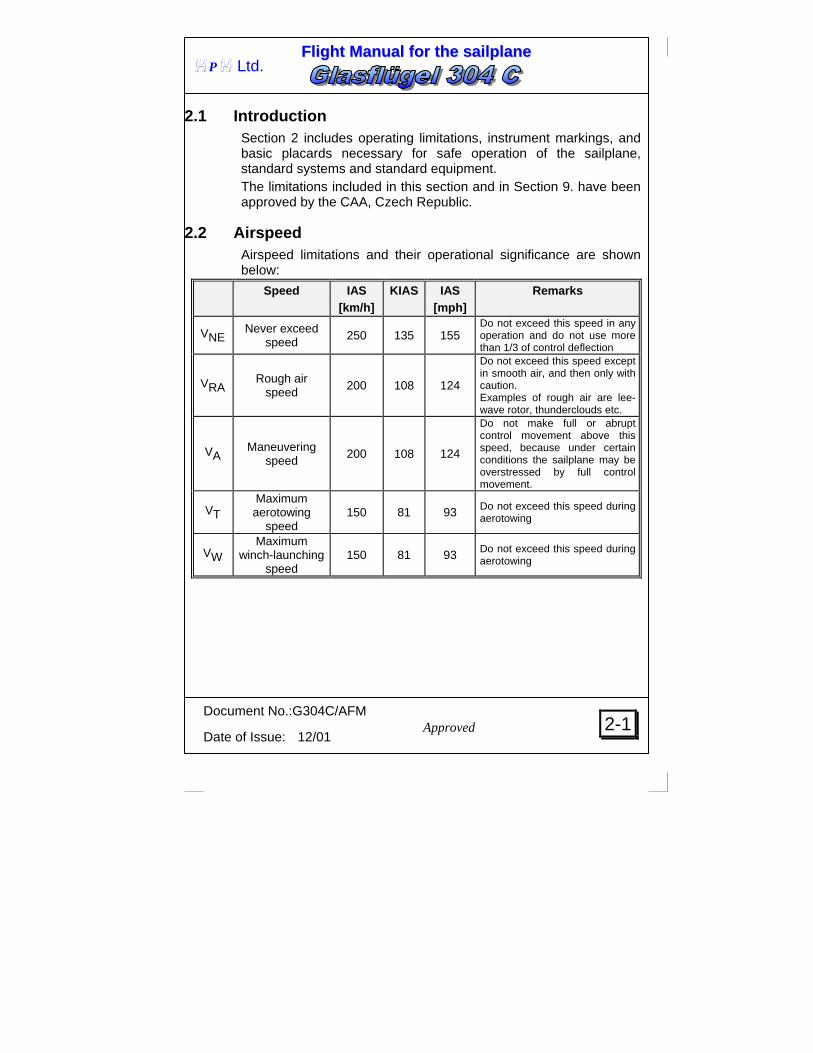
2.1 Introduction Section 2 includes operating limitations, instrument markings, and basic placards necessary for safe operation of the sailplane, standard systems and standard equipment. The limitations included in this section and in Section 9. have been approved by the CAA, Czech Republic.
2.2 Airspeed Airspeed limitations and their operational significance are shown below:
Speed IAS [km/h]
KIAS IAS [mph]
Remarks
VNE Never exceed speed 250 135 155
Do not exceed this speed in any operation and do not use more than 1/3 of control deflection
VRA Rough air speed 200 108 124
Do not exceed this speed except in smooth air, and then only with caution. Examples of rough air are lee-wave rotor, thunderclouds etc.
VA Maneuvering speed
200 108 124
Do not make full or abrupt control movement above this speed, because under certain conditions the sailplane may be overstressed by full control movement.
VT Maximum aerotowing
speed 150 81 93 Do not exceed this speed during
aerotowing
VW Maximum
winch-launching speed
150 81 93 Do not exceed this speed during aerotowing

FFll iigghhtt MMaannuuaall ffoorr tthhee ssaaii llppllaannee
Document No.:G304C/AFM
Date of Issue: 12/01
2-2 Approved
H P H Ltd.
CAUTION Keep in mind, that a difference between Indicated Air Speed (IAS) shown by your airspeed indicator and True Air Speed (TAS) is increasing with an altitude increase. This has no influence on the sailplane strength or load, however due to flutter safety the IAS limits shown in table below must not be exceeded in given altitudes.
Altitude Never exceed speed v NE IAS
[m ISA] [ft ISA] [km/h] KIAS [mph]
0 -
4 000
0 -
13 000 250 135 155
5 000 16 000 240 130 149 6 000 19 500 226 122 140 7 000 22 900 214 116 133 8 000 26 000 202 109 126 9 000 29 500 191 103 119
10 000 32 700 179 97 111 12 000 39 300 159 86 99

FFll iigghhtt MMaannuuaall ffoorr tthhee ssaaii llppllaannee
Document No.:G304C/AFM
Date of Issue: 12/01
2-3 Approved
H P H Ltd.
2.3 Airspeed indicator markings Airspeed indicator markings and their color-code significance are shown below:
Value or range IAS Marking [km/h] KIAS [mph]
Significance
Green arc 94-200 51-108 58-124 Normal operating range
Yellow arc 200-250 108-135 124-155
Maneuvers must be conducted with caution and only in smooth air
Red line 250 135 155 Maximum speed for all
operation. Yellow triangle
85 46 53
Approach speed at maximum weight without water ballast
2.4 Weight Max. take-off weight ...................................450 kg 992 lbs Max. landing weight ...................................450 kg 992 lbs Max. weight of all non-lifting parts..............240 kg 529 lbs (i.e. all parts incl. cockpit and baggage compartment load, with water ballast inside the wing) Maximum weight at basic aerobatic maneuvers..................................380 kg 838 lbs Maximum weight without water ballast ......380 kg 838 lbs Maximum weight in baggage compartment .10 kg 22 lbs (incl. all installed equipment)

FFll iigghhtt MMaannuuaall ffoorr tthhee ssaaii llppllaannee
Document No.:G304C/AFM
Date of Issue: 12/01
2-4 Approved
H P H Ltd.
Maximum water ballast weight is shown in table as follows:
Cockpit load 65 kg 70 kg 80 kg 90 kg 100 kg 110 kg
Empty weight
143 lbs 154 lbs 176 lbs 198 lbs 220 lbs 242 lbs 230 kg 507 lbs
115 kg 254 lbs
115 kg 254 lbs
115 kg 254 lbs
115 kg 254 lbs
115 kg 254 lbs
110 kg 242 lbs
240 kg 529 lbs
115 kg 254 lbs
115 kg 254 lbs
115 kg 254 lbs
115 kg 254 lbs
110 kg 242 lbs
100 kg 220 lbs
250 kg 551 lbs
115 kg 254 lbs
115 kg 254 lbs
115 kg 254 lbs
110 kg 242 lbs
100 kg 220 lbs
90 kg 198 lbs
260 kg 573 lbs
115 kg 254 lbs
115 kg 254 lbs
110 kg 242 lbs
100 kg 220 lbs
90 kg 198 lbs
80 kg 176 lbs
270 kg 595 lbs
115 kg 254 lbs
110 kg 242 lbs
100 kg 220 lbs
90 kg 198 lbs
80 kg 176 lbs
70 kg 154 lbs
280 kg 617 lbs
105 kg 231 lbs
100 kg 220 lbs
90 kg 198 lbs
80 kg 176 lbs
70 kg 154 lbs
60 kg 132 lbs
CAUTION The shaded cockpit load requires a check, whether the maximum weight of all non-lifting parts (240 kg, 529 lbs) will not be exceeded. The maximum baggage weight is 10 kg, 22 lbs including installed equipment and must be considered when establishing the maximum water ballast weight according to the table above.
2.5 Center of Gravity Permitted C.G. range in flight........................... 24.5-42.8 %MAC i.e........................................................................ 200-325 mm behind a reference point – point on the leading edge of the wing root section. Empty sailplane C.G. position for the cockpit load within 70-110 kg (154-242 lbs) must fit into the crosshatched area in the following diagram:

FFll iigghhtt MMaannuuaall ffoorr tthhee ssaaii llppllaannee
Document No.:G304C/AFM
Date of Issue: 12/01
2-5 Approved
H P H Ltd.
If the pilot with a parachute does not reach the placarded minimum cockpit load, the appropriate amount of lead ballast must be carried in the nose. One kg of lead ballast (2.2 lbs) in the ballast box will compensate for 2.4 kg (5.3 lbs) of the pilot‘s weight. Maximum lead ballast capacity of the ballast box is 6 kg (13.2 lbs). Suitable lead ballast plates are available from HPH Ltd. . The empty sailplane C.G. may fit in some cases above or below the crosshatched area of the diagram and the maximum cockpit load is less than 110 kg (242 lbs) or minimum cockpit load is higher than 70 kg (154 lbs). In such case the modification should be approved, at first, as well as recorded in the appropriate documents.

FFll iigghhtt MMaannuuaall ffoorr tthhee ssaaii llppllaannee
Document No.:G304C/AFM
Date of Issue: 12/01
2-6 Approved
H P H Ltd.
2.6 Approved maneuvers This sailplane is certified in the UTILITY category. Approved maneuvers and input air speeds are shown in the following table:
Maneuver Input IAS Spin 60 km/h 32 KIAS 37 mph
Lazy eight 180 km/h 97 KIAS 112 mph
Inside loop 200 km/h 108 KIAS 124 mph
Stall turn (Hammerhead)
200 km/h 108 KIAS 124 mph
2.7 Maneuvering load factors This sailplane is certified in the UTILITY category. The following load factors may not be exceeded during maneuvers: n = +5.3 at air speed VA = 200 km/h, 108 KIAS, 124 mph
-2.65 air brakes retracted n = +4.0 at air speed VNE = 250 km/h, 135 KIAS, 155 mph
-1.5 air brakes retracted n = +3.5 air brakes extended

FFll iigghhtt MMaannuuaall ffoorr tthhee ssaaii llppllaannee
Document No.:G304C/AFM
Date of Issue: 12/01
2-7 Approved
H P H Ltd.
2.8 Flight crew Number of seats ................................ 1 Minimum cockpit load................. 70 kg 154 lbs Maximum cockpit load.............. 110 kg 242 lbs
WARNING If the weight of pilot with parachute does not reach the minimum cockpit load placarded, than appropriate amount of lead ballast must be installed.
2.9 Kinds of operation There are permitted day VFR flights and cloud flying, only.
WARNING Intentional flights in icing conditions are PROHIBITED.
2.10 Minimum equipment The instruments as well as the appropriate parts of the minimum equipment must be of an approved type. Minimum equipment • 1 Airspeed indicator (color marked as in par.2.3.) • 1 Altimeter • 1 set of four-point safety harness • 1 automatic or manual parachute, otherwise back-cushion of
100 mm (4 in) thickness if compressed • 1 Sailplane Flight Manual • Limitation placards in the cockpit

FFll iigghhtt MMaannuuaall ffoorr tthhee ssaaii llppllaannee
Document No.:G304C/AFM
Date of Issue: 12/01
2-8 Approved
H P H Ltd.
Minimum equipment for cloud flights, additionally to the Minimum Equipment : • 1 Magnetic compass • 1 Vertical speed indicator • T/B indicator as well as other equipment as required by the national regulations Equipment for the basic aerobatic maneuvers (Refer to 2.6 for approved maneuvers) Next to the minimum equipment the following is recommended: • 1 g-meter marked with the red radials at +5.3 and –2.65 g.
WARNING Basic aerobatic maneuvers may be performed only without water ballast (max. weight 380kg, 838 lbs).
2.11 Aerotow and winch-launching The standard sailplane is fitted with the C.G. release for a towing rope. Maximum aerotowing speed VT ......... 150 km/h, 81 KIAS, 93 mph Maximum rope or weak-ling strength6400 N For aerotow takeoffs the approved synthetic or natural ropes of 30-60 m (98-296ft.) length may be used. If a nose hook is installed, we recommend to use this one. Nevertheless the C.G. hook is approved for aerotow, too. Winch-launching takeoff Maximum winch-launching speed Vw. 150 km/h, 81 KIAS, 93 mph
WARNING Never use the nose release (if installed) for winch-launching takeoff

FFll iigghhtt MMaannuuaall ffoorr tthhee ssaaii llppllaannee
Document No.:G304C/AFM
Date of Issue: 12/01
2-9 Approved
H P H Ltd.
2.12 Other limitations No smoking inside the sailplane ! Maximum weight of instrument panel .....10 kg.............. 22 lbs

FFll iigghhtt MMaannuuaall ffoorr tthhee ssaaii llppllaannee
Document No.:G304C/AFM
Date of Issue: 12/01
2-10 Approved
H P H Ltd.
2.13 Limitations placards

FFll iigghhtt MMaannuuaall ffoorr tthhee ssaaii llppllaannee
Document No.:G304C/AFM
Date of Issue: 12/01
2-11 Approved
H P H Ltd.
WEIGHT MAX.TAKEOFF WEIGHT 450 kg 992 lbs
MAX. WEIGHT FOR AEROBATIC 380 kg 838 lbs
MAX.WEIGHT OF NON-LIFTING PARTS 240 kg 529 lbs
PERMITTED COCKPIT LOAD 70÷110 kg 154-242 lbs
NOSE BALLAST BALLAST MIN.WEIGHT OF PILOT 1.5 kg 3.3 lbs 66.4 kg 146 lbs
3 kg 6.6 lbs 62.8 kg 138 lbs
4.5 kg 9.9 lbs 59.2 kg 131 lbs
6 kg 13.2 lbs 55.6 kg 123 lbs
PERMITTED AEROBATIC MANOEUVRES SPIN LAZY EIGHT STTALL TURN INSIDE LOOP
AEROBATIC MANOEUVRES ARE PERMITTED ONLY WITHOUT WATER BALLAST
MAX. WEIGHT 380 KG 838 LBS
AIRSPEED IAS VNE Never exceed speed
up to 4000 m / 13000 ft 250 km/h 135 KIAS 155 mph up to 7300 m / 24000 ft 210 km/h 113 KIAS 130 mph up to 10950 m / 36000 ft 170 km/h 92 KIAS 106 mph VA Maneuvering speed 200 km/h 108 KIAS 124 mph VRA Rough air speed 200 km/h108 KIAS 124 mph VT Max. aerotowing speed 150 km/h 81 KIAS 93 mph VW Max. winch-launching speed 150 km/h 81 KIAS 93 mph

FFll iigghhtt MMaannuuaall ffoorr tthhee ssaaii llppllaannee
Document No.:G304C/AFM
Date of Issue: 12/01
3-0 Approved
H P H Ltd.
SECTION 3
3. Emergency procedures 3.1 Introduction 3.2 Canopy jettison 3.3 Bailing out 3.4 Stall recovery 3.5 Spin recovery 3.6 Spiral dive recovery 3.7 Other emergencies 3.7.1 Wingtip catching in high grass during takeoff 3.7.2 Cable chute opening during winch-launching 3.7.3 Towing rope release at low height 3.7.4 Slight vibrations and spongy controls before the stall

FFll iigghhtt MMaannuuaall ffoorr tthhee ssaaii llppllaannee
Document No.:G304C/AFM
Date of Issue: 12/01
3-1 Approved
H P H Ltd.
3.1 Introduction Section 3 provides checklist and amplified procedures for coping with emergencies that may occur.
3.2 Canopy jettison 1. Grasp (from below) the red grips (right and left of the canopy
frame) 2. Pull them back 3. Push the canopy upward.
3.3 Bailing out 1. Direct the sailplane to an uninhabited place 2. Canopy jettison acc. to 3.2 3. Release safety harness and spread them aside 4. Bend you legs under the body 5. Roll over the cockpit frame
3.4 Stall recovery 1. Push the control stick forward 2. After stall recovery transit to gliding.
3.5 Spin recovery 1. Control stick - ailerons in neutral position 2. Rudder pedals - full deflection opposite to the direction of
the spin 3. Control stick - Release back pressure on the control
stick until the rotation stops 4. Neutralize rudder and recover the dive
FFll iigghhtt MMaannuuaall ffoorr tthhee ssaaii llppllaannee
Document No.:G304C/AFM
Date of Issue: 12/01
3-2 Approved
H P H Ltd.
3.6 Spiral dive recovery 1. Balance the bank by coordinate use of rudder and ailerons
controls 2. Recover the dive
3.7 Other emergencies
3.7.1 Wingtip catching in high grass during takeoff Take-Off's from not mowed grass runways should be avoided both for aerotow and winch-launching. Should a wingtip be caught in high grass, release immediately, delaying this may result in a ground loop.
3.7.2 Cable chute opening during winch-launching In the early phase of a winch-launching, the cable chute may open if it’s size is too large or if the climb is too flat. In such case release immediately and land straight ahead.
3.7.3 Towing rope release at low height A speed within 85-90 km/h (46-49kts, 53-56mph) should be maintained after release at low height in straight and level flight (the speed increases up to 15 % with water ballast!). In a turn the speed should be increased according to the angle of bank. In this manner the unintentional and unnoticed stalled flight will be avoided.
3.7.4 Slight vibrations and spongy controls before the stall Should you detect a slight vibration, with "spongy" controls and the air speed indicator varying between 65- 85 km/h (35-46 KIAS, 40-53 mph), the sailplane is in stalled flight. Move the control stick forward, at once.

FFll iigghhtt MMaannuuaall ffoorr tthhee ssaaii llppllaannee
Document No.:G304C/AFM
Date of Issue: 12/01
4-0 Approved
H P H Ltd.
SECTION 4
4. Normal procedures 4.1 Introduction 4.2 Rigging and de-rigging Daily inspection 4.4 Preflight inspection 4.5 Normal procedures and recommended speeds 4.5.1 Takeoff and climbing 4.5.2 Flight 4.5.3 Approach and landing 4.5.4 Flying with water ballast 4.5.5 High speed flight 4.5.6 Slow speed flight – stall characteristics 4.5.7 Cloud flying 4.5.8 Flights below zero 4.5.9 Flight in rain 4.5.10 Aerobatics

FFll iigghhtt MMaannuuaall ffoorr tthhee ssaaii llppllaannee
Document No.:G304C/AFM
Date of Issue: 12/01
4-1 Approved
H P H Ltd.
4.1 Introduction Section 4 provides checklist and amplified procedures for the conduct of normal operation. Normal procedures associated with optional systems can be found in section 9.
4.2 Rigging and de-rigging Rigging 1. Clean and grease pins and bearings. 2. In the cockpit, the airbrake lever is set in the central position,
and the water ballast lever set in the closed position. 3. First rig Port wing, temporarily lock with the main pin by
engaging it only into the front spar fork bush. Pay attention that the bellcranks on the root rib are in their neutral position and are actually engaging into the opposing socket fittings on the fuselage.
4. Rig Starboard wing with the same lever settings as Port wing, and pull together with rigging tool. Ensure correct engagement of control as with Port wing.
5. Momentarily remove main wing spar pin. When bushes line up push pin in and lock.
6. Check aileron and airbrake functions. 7. Push tailplane onto the rigging - drive pins and pull out front
connection pin with tool, push tailplane L.E. down and push front connection pin fully into position, remove tool. Check that the elevator rigging-drive pins are actually correctly engaged into their opposing elevator fittings (move elevator).
8. Tape off gaps. De-rigging 1. Pull front tailplane connection pin out, with the help of the tool,
and lift up tailplane. 2. Lift wingtips and remove main pin. 3. With the help of the rigging tool, or by pulling on the wingtips,
separate the wings from the fuselage.

FFll iigghhtt MMaannuuaall ffoorr tthhee ssaaii llppllaannee
Document No.:G304C/AFM
Date of Issue: 12/01
4-2 Approved
H P H Ltd.
4.3 Daily inspection
Daily inspection should be performed before each flight day opening, both after rigging the sailplane and parking in a hangar. When inspecting the sailplane check for cracks in surface finish, blisters or uneven surface, and if in doubt, check with authorized, specialized personnel.
1 a) Open the cockpit, check if the main pin is installed and locked. b) Visual cockpit control inspection. c) Remove foreign material from fuselage. d) Check tire pressure of main wheel
Tire size 5.00-5 Takeoff weight
[kg]
Main wheel pressure
[kPa] 350 250 400 300 450 350

FFll iigghhtt MMaannuuaall ffoorr tthhee ssaaii llppllaannee
Document No.:G304C/AFM
Date of Issue: 12/01
4-3 Approved
H P H Ltd.
e) Check function of tow release, condition and spacing of cable deflector plates.
2 a) Check ailerons for full and free movement.
3 a) Check air brakes for free movement and close fit. b) Check aileron trailing edges for damage.
Lightly shake ailerons on the trailing edge to detect unusually large play in the system.
c) Check hinges for any damage.
4 a) Check if the holes for static pressure on the fuselage shell are clear.
5 a) Check if the front stabilizer attachment bolt is engaged. b) Check for blocked Pitot, gently blow into the Pitot to check ASI
function. c) Fit compensatory tube and check line. When blowing against
tube, the connected vertical speed indicator registers "climb". d) Check tire pressure in tail wheel...150 kPa.
6 a) Check elevator and rudder for free and full movement. b) Check elevator and rudder for damage,
lightly shake by hand on trailing edge to check for unusually large play in system.
7 Refer to 3.

FFll iigghhtt MMaannuuaall ffoorr tthhee ssaaii llppllaannee
Document No.:G304C/AFM
Date of Issue: 12/01
4-4 Approved
H P H Ltd.
8 Refer to 2.
9
Check the function of the nose release mechanism (if installed). After a hard landing, or excessively high "G" loads, the bending frequency of the wings must be checked and the sailplane carefully examined for any indications of damage. Dismantle the sailplane and check surface finish for cracks. Look for white areas (that may indicate delamination) at the wing spar root ends, wing root rib fittings, landing gear attachments, tail fittings, and all areas of concentrated loads. Also inspect the central wing pin and tail attachments for distortion. If damage is found, the sailplane should be grounded until any repairs have been completed.
4.4 Preflight inspection • Parachute correctly fitted? • Safety harness correctly and firmly adjusted? • Backrest and pedals locked in comfortable position? • All controls and instruments within easy reach? • Airbrakes locked? • Control check? • Free, full and correct movements of controls? • Correct trim position? • Canopy locked? • Release check? • Towline on correct release - correct weak-link? • Set Altimeter!

FFll iigghhtt MMaannuuaall ffoorr tthhee ssaaii llppllaannee
Document No.:G304C/AFM
Date of Issue: 12/01
4-5 Approved
H P H Ltd.
4.5 Normal procedures and recommended speeds
4.5.1 Takeoff and climbing Aerotow Approved ropes made of synthetic and natural fibers with length from 30 to 60 m (98 - 196ft.) may be used for aerotowing. If a nose hook is installed, we recommend to use this one. Nevertheless the C.G. hook is approved for aerotow, too. When commencing the take-off run, use wheel brake slightly to prevent rolling over tow rope. Before takeoff adjust the trim depending on the cockpit load. The trim should be in neutral position if the sailplane C.G. ranges from forward to medium position. If the C.G. ranges from medium to rear position, then trim "nose heavy". After lift-off and when a speed of about 75-80 km/h (40-43KIAS, 47-50 mph) is reached (this speed is increasing up to 15 % with the water ballast), adjust the trim to decrease elevator control forces. Normal towing speed .. 100-120 km/h 54-65 KIAS 62-75 mph Max. aerotowing speed .......150 km/h 81 KIAS 93 mph The main landing gear can be retracted during tow. Should the sailplane be unintentionally displaced laterally, it should be cautiously but immediately steered back to normal aerotow position. Should the sailplane be displaced vertically too high, with a danger of over-flying the tow aircraft, the air brakes should be open. Rope release: Pull the release knob several times to be sure, that the rope was released.

FFll iigghhtt MMaannuuaall ffoorr tthhee ssaaii llppllaannee
Document No.:G304C/AFM
Date of Issue: 12/01
4-6 Approved
H P H Ltd.
Winch-launching
WARNING NEVER use the nose release mechanism (if installed) for winch-launching!
Before takeoff adjust the trim depending on the cockpit load. The trim should be in neutral position if the sailplane C.G. ranges from forward to medium position. If the C.G. ranges from medium to rear position, then trim "nose heavy". When commencing the take-off run, use wheel brake slightly to prevent rolling over tow rope. This sailplane shows normal behavior during winch-launching and even with rear C.G. positions has only a minor tendency to enter into a steep climb after take-off. Depending on the trim-setting, a correction with the elevator may be necessary to prevent a steep climb in the early take-off phase. After a safety height of approx. 50m (150ft) is reached, the sailplane can be brought into a steeper climb by more back pressure on the control column. If too much back pressure is applied and proposing occurs (elevator stall), release some of the back pressure. Avoid rapid lift-off maneuvers or low towing speeds. The high wing loading of this sailplane requires the pilot to abort the take-off and release, if the towing speed drops below 95 km/h, 51 KIAS.
WARNING The low performance winches with limited engine RPM and other limitations, as well as the takeoff at the tail wind conditions, calm air, filled water tanks etc., require special attention before take-off, to ensure that the winch is providing enough power in reserve to maintain the safe towing speeds.

FFll iigghhtt MMaannuuaall ffoorr tthhee ssaaii llppllaannee
Document No.:G304C/AFM
Date of Issue: 12/01
4-7 Approved
H P H Ltd.
If possible, use small cable chutes to prevent deploying at flat climb angles. Max. winch-launching speed VW 150 km/h 81 KIAS 93 mph Normal minimum towing speed.. 105 km/h 57 KIAS 65 mph with water ballast........................ 120 km/h 65 KIAS 75 mph At maximum towing height, the cable will back release automatically, however, you should not neglect to pull the release knob several times.
4.5.2 Flight At a safe altitude, experiment with the air brakes and note loss of height at various speeds. This sailplane has very well balanced flight characteristics and controls. The rate of roll from 45o bank at 1.4 times stalling speed is 3.5 sec. On the other hand, it is possible to fly with free controls in straight and level or circling flight without the sailplane changing its attitude or speed. All control movements require only very low operating forces.

FFll iigghhtt MMaannuuaall ffoorr tthhee ssaaii llppllaannee
Document No.:G304C/AFM
Date of Issue: 12/01
4-8 Approved
H P H Ltd.
4.5.3 Approach and landing The normal approach speed with air brakes fully extended and the extended landing gear is approx. 85-90 km/h (46-49 KIAS, 53-56 mph) at the landing weight of 380 kg (838 lbs). The corresponding gliding ratio is then approx. 1:5. The minimum approach speed is 80 km/h (43 KIAS, 50 mph). Immediately before touch-down, the air brakes should be always open fully. The approach speeds have to be increased of approx. 10 km/h (5.4 KIAS, 6.2 mph) at the landing weight of 450 kg (932 lbs). For steep approaches (e.g. in strong ground turbulence or when approaching over high obstacles) the air brakes are fully extended, and the glide angle is controlled with the elevator. Excessive height can thus be reduced without increasing approach speed noticeably.
WARNING The water ballast (if filled) should be emptied before landing. If a sideslip is used to reduce the approach height with air brakes and landing gear extended, than apply only 1/2 of rudder pedal deflection. If higher deflection is used than the rudder is affected by the wake behind the air brakes and the vibration of the sailplane may occurs. If the rudder full deflection is applied than the rudder suction will occur. If the vibration during a sideslip occur, reduce the air brakes extension to 1/2 of full deflection and recover level flight, than the air brakes may be fully extended again.

FFll iigghhtt MMaannuuaall ffoorr tthhee ssaaii llppllaannee
Document No.:G304C/AFM
Date of Issue: 12/01
4-9 Approved
H P H Ltd.
4.5.4 Flying with water ballast The use of water ballast is not of benefit when climbing at the average climbing speeds less than 1.5m/sec (300 ft/min). This is valid also for flights in tight thermals, which require steep angles of bank. Prior to adding water ballast, check the table in 2.4 for the maximum weight of water ballast. The total capacity of the bags in the wings is 115 liters (25.3 UKgal, 30.4 USgal). Fill through the valves in the lower surface of the wings. Let the actuating lever in "close" position, fill left bag, disconnect the filler tube from the valve (it will be closed automatically), fill right bag by the same steps as the left.
WARNING Bags must not be pressurized, e.g. fill directly from the water hose. Both bags must be filled equally. Do not add water ballast below O°C (32 oF), because of freezing danger. The water ballast should be emptied before landing. It takes about 4 minutes when the bags were full. Never store the sailplane with filled bags. Always drain off water and open the valves to vent the water bags.
4.5.5 High speed flight During high speed flight, pay attention to the never exceed speed. Refer to 2.2 and 2.3 for the Airspeed limits and Airspeed Indicator Marking. Aileron and rudder full deflections may be applied up to the Maneuvering speed Full control deflections of aileron and rudder are allowable up to VA=200 km/h IAS (108 KIAS, 124 mph).
Only 1/3 of the aileron and rudder full deflections may be used at Never exceed speed VA=250 km/h IAS (135 KIAS, 156 mph).
Elevator deflections must be limited, as well, to not exceed the load factors shown in 2.7.

FFll iigghhtt MMaannuuaall ffoorr tthhee ssaaii llppllaannee
Document No.:G304C/AFM
Date of Issue: 12/01
4-10 Approved
H P H Ltd.
During extreme turbulence, as it may occur for instance in wave rotors, thunderclouds, visible up-currents (stubble fire), or while crossing mountain ranges, the maximum speed in rough air VRA 200 km/h (108 KIAS, 124mph) should not be exceeded. The necessary control column travel is relatively small from the stalling speed to the maximum speed, in particular at rear C.G. positions, however any speed change will be noticed by a change of the control forces. The air brakes can be open up to VNE = 250 km/h (135 KIAS, 155 mph), however this should only be done in an emergency or when unintentionally exceeding the maximum permissible speeds shown in 2.2, which is indicated by a sudden deceleration. For this reason, ensure that your harness is tight, and that you do not unintentionally move or jolt the control column while operating the air brake lever. Loose objects in the cockpit should be avoided, as well.
4.5.6 Slow speed flight – stall characteristics For familiarization with Glasflügel 304 C sailplane, we recommend to perform stalling tests from a straight and level flight, and from a turn of 45° bank. The tests should be done of course at a safe altitude. Refer to Section 5. par. 5.2.2 for the sailplane stalling speeds. With closed air brakes, a stall warning occurs as a light buffeting and vibration and oscillation of the ASI needle towards the stalling speed. If the air brakes are extended, the airframe vibrates noticeably at approx. 5km/h (2 kts, 3mph) above the stalling speed. If the control column is slowly pulled back, a stall occurs, which is evidenced by a downward pitching motion or rolling motion. The back pressure on the control column should then be immediately released. If the air brakes are extended, the loss of altitude after wing drop is approx. 50m (150 ft). With medium and forward C.G. positions you can produce and correct roll and yaw during stall. This is shown itself by "spongy" controls, increasing of the sinking speed and oscillation of the ASI needle.

FFll iigghhtt MMaannuuaall ffoorr tthhee ssaaii llppllaannee
Document No.:G304C/AFM
Date of Issue: 12/01
4-11 Approved
H P H Ltd.
4.5.7 Cloud flying The spin should not be used as a safety escape outside a cloud, as the sailplane may change over into a spiral dive. It is rather recommended to open the air brakes fully at speed of 130 km/h IAS (70 KIAS, 81mph) and at load factor above 2 "G". At speeds above 150 km/h IAS (81 KIAS, 93 mph) the air brakes should not be closed, as this sailplane, owing to its very steep glide path, may exceed the never exceed speed. Minimum equipment for the cloud flying is listed in 2.10.
4.5.8 Flights below zero The control system friction may increase when the temperature is below zero degrees of Centigrade, as well as during winter flying. Ensure that all control elements are free of moisture to prevent freezing. This, in particular, applies to the AIR BRAKES. Continuously operate controls and air brakes at short intervals. During flights with water ballast, note the recommendation under 4.5.4.
4.5.9 Flight in rain Neither any special actions are required when flying in rain nor the flight characteristics are significantly affected.

FFll iigghhtt MMaannuuaall ffoorr tthhee ssaaii llppllaannee
Document No.:G304C/AFM
Date of Issue: 12/01
4-12 Approved
H P H Ltd.
4.5.10 Aerobatics Refer to 2.6 for Approved maneuvers Inside loop Slightly push the control stick forward to increase sailplane speed above 180 km/h IAS (97 KIAS, 112 mph) (recommended is 200 km/h, 108 KIAS, 124 mph). Then continuously pull the stick so that the sailplane nose will be lifted and g acting on the pilot will increase continuously. After reaching the position with nose up, the control stick force will be slightly reduced due to speed decrease. Continue to pull the stick and the speed will start to increase when exceeding the loop culmination point. To smoothly recover the loop release back pressure on the control stick, so that the loop remains smooth Spin Spins may be performed only at rear C.G. positions. With forward C.G. positions, this sailplane will enter a spiral dive. It should be terminated immediately by neutralizing all controls and recover. To enter the spin, a dynamic stall has to be produced, and before nose drop, full rudder has to be applied into the direction of spin. Entry speed: 60 km/h IAS, 32 KIAS, 37mph Recovery speed: 150-180km/h, 81-97 KIAS, 93-112mph The spin recovery is achieved by neutralizing the elevator and applying rudder against the rotation. Stall turn(Hammerhead) Slightly push the control stick forward to reach entry speed not less than 180 km/h IAS (97 KIAS, 112 mph) (recommended is 200 km/h, 108 KIAS, 124 mph). Lift the sailplane nose 60°-70° above horizon. When the speed drops at 130 km/h IAS (70 KIAS, 81 mph) start to gradually apply the rudder deflection into the required stall turn direction. As the rudder control force is decreasing, speed up the rudder deflection until its full deflection is reached.

FFll iigghhtt MMaannuuaall ffoorr tthhee ssaaii llppllaannee
Document No.:G304C/AFM
Date of Issue: 12/01
4-13 Approved
H P H Ltd.
Proportionally opposite ailerons may help to maintain the plane of turning. After the sailplane turns its nose downward into opposite direction, neutralize ailerons and rudder, so that the sailplane flies out accurately into opposite direction (180°). Recover gently without exceeding the load factors. Lazy eight Slightly push the control stick forward to reach entry speed not less than 180 km/h IAS (97 KIAS, 112 mph) (recommended is 200 km/h, 108 KIAS, 124 mph). Gradually pull the control stick while coordinately applying the ailerons and rudder to perform a climbing turn in required direction. At a speed of 120 km/h IAS (65 KIAS, 75 mph) change to gliding at 180 km/h IAS (97 KIAS, 112 mph) and gradually pull the stick while coordinately applying the ailerons and rudder to perform opposite climbing turn. The trajectory intersection is in the lowest point of the eight. In steep turns, the following speeds, depending on load factor, and degree of bank, should not be less than :
Load factor Angle of bank speed
+2,0 +2,5 +3,0 +3,5
60° 65° 70° 73°
110 km/h 59 KIAS 68 mph 125 km/h 67 KIAS 78 mph 135 km/h 73 KIAS 84 mph 150 km/h 81 KIAS 93 mph

FFll iigghhtt MMaannuuaall ffoorr tthhee ssaaii llppllaannee
Document No.: G304C/AFM
Date of Issue: 12/01
5-0
H P H Ltd.
SECTION 5
5. Performance 5.1 Introduction 5.2 Approved data 5.2.1 Airspeed indicator system calibration 5.2.2 Stall speeds 5.3 Non-approved further information 5.3.1 Demonstrated crosswind performance 5.3.2 Speed polar
Approved

FFll iigghhtt MMaannuuaall ffoorr tthhee ssaaii llppllaannee
Document No.: G304C/AFM
Date of Issue: 12/01
5-1
H P H Ltd.
5.1 Introduction Section 5 provides approved data for airspeed calibration, stall speeds and non-approved further information. The data in the charts has been computed from actual flight tests with the sailplane using average piloting techniques.
Approved

FFll iigghhtt MMaannuuaall ffoorr tthhee ssaaii llppllaannee
Document No.: G304C/AFM
Date of Issue: 12/01
5-2
H P H Ltd.
5.2 Approved data
5.2.1 Airspeed indicator system calibration
Approved

FFll iigghhtt MMaannuuaall ffoorr tthhee ssaaii llppllaannee
Document No.: G304C/AFM
Date of Issue: 12/01
5-3
H P H Ltd.
5.2.2 Stall speeds Air brakes Takeoff Weight
350 kg 175 lbs
400 kg 200 lbs
450 kg 225 lbs
60 km/h 75 km/h 81 km/h 32 KIAS 40 KIAS 44 KIAS Retracted
37 mph 47 mph 50 mph 67 km/h 80 km/h 85 km/h 36 KIAS 43 KIAS 46 KIAS Extended
42 mph 50 mph 53 mph With closed air brakes, a stall warning occurs as a light buffeting and vibration and oscillation of the ASI needle towards the stalling speed. If the air brakes are extended, the airframe vibrates noticeably at approx. 5km/h (2 kts, 3mph) above the stalling speed. If the air brakes are extended, the loss of altitude after wing drop is approx. 50m (150 ft).
Approved

FFll iigghhtt MMaannuuaall ffoorr tthhee ssaaii llppllaannee
Document No.: G304C/AFM
Date of Issue: 12/01
5-4
H P H Ltd.
5.3 Non-approved further information
5.3.1 Demonstrated crosswind performance Winch-launching takeoff........25 km/h 6.9 m/s 13.5 kts Aerotow takeoff .....................23 km/h 6.4 m/s 12.4 kts Landing..................................23 km/h 6.4 m/s 12.4 kts
5.3.2 Speed polar Not measured so far

FFll iigghhtt MMaannuuaall ffoorr tthhee ssaaii llppllaannee
Document No.: G304C/AFM
Date of Issue: 12/01
6-0
H P H Ltd.
SECTION 6
6. Weight and Balance 6.1 Introduction 6.2 Weight and Balance Record and permitted payload -range

FFll iigghhtt MMaannuuaall ffoorr tthhee ssaaii llppllaannee
Document No.: G304C/AFM
Date of Issue: 12/01
6-1
H P H Ltd.
6.1 Introduction This Section contains the payload range within the sailplane may be safely operated. Procedures for weighing the sailplane and the calculation method for establishing the permitted payload range and a comprehensive list of all equipment available for this sailplane and the installed equipment during the weighing of the sailplane are contained in the applicable Maintenance Manual, Document Number G304C/MM.

FFll iigghhtt MMaannuuaall ffoorr tthhee ssaaii llppllaannee
Document No.: G304C/AFM
Date of Issue: 12/01
6-2
H P H Ltd.
6.2 Weight and Balance Record and permitted payload -range
valid for Serial No.:
Permitted cockpit load [kg] or [lbs] with
water ballast without
water-ballast Approved
Date Empty weight
Max. Min. Max. Min. Date Signature
Refer to Operating, Maintenance and Repair Manual, Document Number G304C/MM for minimum and maximum pilot weight calculation.

FFll iigghhtt MMaannuuaall ffoorr tthhee ssaaii llppllaannee
Document No.: G304C/AFM
Date of Issue: 12/01
7-0
H P H Ltd.
SECTION 7
7. GENERAL SAILPLANE AND SYSTEMS DESCRIPTION
7.1 Introduction 7.2 Cockpit controls 7.3 Instrument panel 7.4 Landing gear system 7.5 Seats and safety harness 7.6 Pitot and static system 7.7 Airbrake system 7.8 Baggage compartment 7.9 Water-ballast system
FFll iigghhtt MMaannuuaall ffoorr tthhee ssaaii llppllaannee
Document No.: G304C/AFM
Date of Issue: 12/01
7-1
H P H Ltd.
7.1 Introduction This Section provides description and operation of the sailplane and its systems. Refer to Section 9, Supplements, for details of optional systems and equipment.
7.2 Cockpit controls The below listed controls marked by the appropriate placards (refer to 2.13) are installed in the cockpit. More detailed description of some of the systems may be found below. Control Column The elevator is moved by a parallelogram system which prevents unintentional movements induced by gusts. The following buttons are mounted on the control column: a) Radio button
press to transmit. b) Spring trim button
depress with the little finger and release in any selected control column position.
c) Trim lever can be adjusted manually when trim button is depressed. Lever forward: nose heavy Lever rearward: tail heavy
d) Wheel brake It is controlled by means of the rudder pedals.
e) Tow Release The yellow grip under the Port side of the instrument panel is activating both releases.
f) Air brakes Air brakes are operated by a blue lever located on the port side of the cockpit EXTEND: Unlock (inwards) blue lever on the Port cockpit side and pull towards the rear. RETRACT: Push lever forward and lock.

FFll iigghhtt MMaannuuaall ffoorr tthhee ssaaii llppllaannee
Document No.: G304C/AFM
Date of Issue: 12/01
7-2
H P H Ltd.
g) Canopy Lock The white grips on both sides of the cockpit frame serve for the canopy opening-closing. Closing: Handle the canopy frame, pull it downward and push white grips forward until they snap. Opening: Pull both white grips rearward and push canopy frame upward.
h) Cockpit Ventilation Cockpit ventilation is operated with a black knob located on the instrument panel. Pull the knob to open ventilation Push the knob to close ventilation Butterfly valve closed - air supply to the canopy only Butterfly valve open - air supply to the pilot as well as to the canopy
i) Water ballast Water ballast system is operated with a small lever located on the starboard cockpit side. Lever at rear position: Valves open Lever in forward position: Valves close
j) Backrest adjustment Backrest position may be adjusted with a black "D" lever on the starboard cockpit side.
k) Knee rests May be adjusted by means of the two air pumps
l) Rudder pedal adjustment By pulling the black "T" - grip under the instrument panel, the panel adjustment is unlocked. Forward adjustment: Pull black "T"-grip while pushing pedals forward with heels, release grip and let pedals lock into position. Rear adjustment: Pull pedals back with black grip.

FFll iigghhtt MMaannuuaall ffoorr tthhee ssaaii llppllaannee
Document No.: G304C/AFM
Date of Issue: 12/01
7-3
H P H Ltd.
7.3 Instrument panel

FFll iigghhtt MMaannuuaall ffoorr tthhee ssaaii llppllaannee
Document No.: G304C/AFM
Date of Issue: 12/01
7-4
H P H Ltd.
7.4 Landing gear system The sailplane is fitted with a retractable main wheel and auxiliary tail wheel. The main landing gear is operated with a black lever located on the cockpit starboard side. to retract: Unlock black handle, pull backwards, then lock. to extend: Unlock, push black handle forward and lock. To apply brake on the main wheel push by your heels on rudder pedals (if necessary the pedals position may be adjusted rearward of 1-2 notches prior to landing).
7.5 Seats and safety harness The sailplane is fitted with an adjustable backrest as well as headrest. The backrest position may be adjusted with a black "D" lever on the starboard cockpit side. To adjust the backrest position release the lever, release weight on the backrest and move your body forward; the backrest moves forward. To adjust the headrest: Lift notched bar and adjust headrest position. Both backrest and headrest may be adjusted in flight. There are four-points safety harness.
7.6 Pitot and static system The static pressure orifices are located on both sides of the fuselage. Total pressure is read in the fuselage nose. Keep the static pressure holes clean, refer to 0
Daily inspection.
7.7 Airbrake system The air brakes are controlled with the blue lever located on the port side of the cockpit. To extend the air brakes pull the lever rearward To retract the air brakes push the lever forward

FFll iigghhtt MMaannuuaall ffoorr tthhee ssaaii llppllaannee
Document No.: G304C/AFM
Date of Issue: 12/01
7-5
H P H Ltd.
7.8 Baggage compartment The baggage compartment may carry up to 10 kg (22 lbs) of baggage including all installed equipment, from that 5 kg (11 lbs) may be placed loose i.e. without fastening with the straps.
7.9 Water-ballast system The water-ballast system is operated with a small lever located on the starboard side of the cockpit. open valves – lever in rearward position closed valves – lever in forward position The two replaceable water ballast bags can carry up to 115 liters (25.3 UKgal, 30.4 USgal).

FFll iigghhtt MMaannuuaall ffoorr tthhee ssaaii llppllaannee
Document No.: G304C/AFM
Date of Issue: 12/01
8-0
H P H Ltd.
SECTION 8
8. Sailplane handling, care and maintenance 8.1 Introduction 8.2 Sailplane inspection periods 8.3 Sailplane alterations or repairs 8.4 Ground handling / road transport 8.5 Cleaning and care

FFll iigghhtt MMaannuuaall ffoorr tthhee ssaaii llppllaannee
Document No.: G304C/AFM
Date of Issue: 12/01
8-1
H P H Ltd.
8.1 Introduction This Section contains manufacturer's recommended procedures for proper ground handling and servicing of the powered sailplane. It also identifies certain inspection and maintenance requirements which must be followed if the sailplane is to retain that new-plane performance and dependability. It is wise to follow a planned schedule of lubrication and preventive maintenance based on climatic and flying conditions encountered.
8.2 Sailplane inspection periods Refer to the Operating, Maintenance and Repair Manual, Document Number G304C/MM for more information on the sailplane periodical inspections.
8.3 Sailplane alterations or repairs It is essential that the responsible airworthiness Authority be contacted prior to any alterations on the sailplane to ensure that the airworthiness of the sailplane is not compromised. Refer to the Operating, Maintenance and Repair Manual, Document Number G304C/MM for more information on the sailplane repairs.

FFll iigghhtt MMaannuuaall ffoorr tthhee ssaaii llppllaannee
Document No.: G304C/AFM
Date of Issue: 12/01
8-2
H P H Ltd.
8.4 Ground handling / road transport The sailplane should only be stored or parked in well ventilated areas. Closed trailers should be equipped with sufficiently large ventilation. Always store with empty water tanks. Take note to store the sailplane without stresses. This is particularly important at higher temperatures. Because of their slim shape, it is particularly important to store the wings correctly. They should be stored with the L.E. pointing downwards and supported under the wing root spar at approx. 2.4 m (7.9 ft) from the wingtip, in a profile true wing sling. Fuselage is correctly stored in a wide fuselage molding in front of the C.G. release, and supported by the tail wheel. The Tailplane is stored in two profile true slings, separated 1.5-2m (5 -6.6 ft.), and with the L.E. pointing downward. Under no circumstances attach the tailplane into the trailer by using the tailplane main attachment fittings. Sailplanes which stay rigged for the whole year or longer periods, should be attended to, so that rigging elements on the fuselage, wing and tailplane do not corrode. Dust covers should be used and are highly recommended. The sailplane should not be parked in the open with the canopy in the open position, as this may act as a concave mirror, and depending on direction of sun-radiation, constitutes a fire hazard. A tail dolly should always be used for ground-handling this sailplane, to prevent unnecessary vibration of the tailplane, and stresses and wear to its attachment fittings. When ground-handling, do not push at wingtips, but rather close to the fuselage.

FFll iigghhtt MMaannuuaall ffoorr tthhee ssaaii llppllaannee
Document No.: G304C/AFM
Date of Issue: 12/01
8-3
H P H Ltd.
8.5 Cleaning and care Wash the surface only with clean water, sponge and chamois. Never use petrol, alcohol or thinners. Soap additives in water should not be used too often. Polish as often as you wish, but take care not to heat up the surface when using a polishing machine, as otherwise the surface quality will suffer. Exposure to moisture should be avoided, as with all other sailplanes. Protect from intensive sun-radiation (heat), and unnecessary permanent load. Please note that the surface of all parts which are exposed to sun-radiation must be colored white. Colors other than white will increase the heat build-up in the GRP, so that insufficient strength will result.

FFll iigghhtt MMaannuuaall ffoorr tthhee ssaaii llppllaannee
Document No.: G304C/AFM
Date of Issue: 12/01
9-0
H P H Ltd.
SECTION 9
9. Supplements 9.1 Introduction 9.2 List of inserted supplements 9.3 Supplements inserted

FFll iigghhtt MMaannuuaall ffoorr tthhee ssaaii llppllaannee
Document No.: G304C/AFM
Date of Issue: 12/01
9-1
H P H Ltd.
9.1 Introduction
9.2 List of inserted supplements
Date of insertion
Doc.No. Title of inserted supplement

FFll iigghhtt MMaannuuaall ffoorr tthhee ssaaii llppllaannee
Document No.: G304C/AFM
Date of Issue: 12/01
9-2
H P H Ltd.
9.3 Supplements inserted