flight in icing conditions - accueil · flight in icing conditions summary prepared by: giuseppe...
TRANSCRIPT

Summary: page 1
FLIGHT IN ICING CONDITIONS
SUMMARY
Prepared by: Giuseppe Mingione (CIRA), Massimo Barocco (ANPAC) with the co-operation of: Eugenio Denti, Francesco Giuseppe Bindi (University of Pisa) On behalf of: French DGAC

Summary: page 2
1) METEOROLOGICAL FACTORS 4 2) ICE ACCRETION 7 3) AERODYNAMICS DEGRADATION 11 4) ICING SEVERITY INDEX 12 5) ICE DETECTION 13 6) ICE PROTECTION 16
6.1) Ground icing 16 6.1) In-flight icing 16
6) AIRCRAFT OPERATION: EFFECT OF ICE ON AIRCRAFT 20
7.1) Wing stall 20 7.1.1) Description 20 7.1.2) Avoidance 20 7.1.3) Recovery 21
7.2) Icing Contaminated Tail Stall (ICTS) 21 7.2.1) Description 21 7.2.2) Identification 22 7.2.3) Avoidance 23 7.2.4) Recovery 23
7.3) Icing contaminated roll upset 23 7.3.1) Description 23 7.3.2) Avoidance 24 7.3.3) Recovery 26
7.4) Ground icing 26 7.5) Engine and induction 31 7.6) Carburetor icing 31
7.6.1) Description 31 7.6.2) Identification 32 7.6.3) Avoidance 33 7.6.4) Recovery 33
7.7) Propeller icing 34 7.8) Instrument icing 34
7.8.1) Antenna 34 7.8.2) Pitot 34 7.8.3) EPR 35 7.8.4) Stall warning 35
7.9) Windshield 35
8) AIRCRAFT OPERATION 36 8.1) Weather analysis 37 8.2) Pre-flight 38 8.3) Taxing 39 8.4) Take-off 40 8.5) Climb-out 41 8.6) Cruise 42 8.7) Descent 43 8.8) Approach and landing 44
9) GLOSSARY 45

Summary: page 3
IMPORTANT NOTICES
SINCE THIS BOOK DOES NOT ADDRESS A SPECIFIC AIRCRAFT BUT ADDRESS ANY CATEGORIES, ALL CONSIDERATIONS REPORTED MUST ALWAYS CROSS-CHECKED WITH RECOMMENDED AIRCRAFT FLIGHT MANUAL (AFM). THEREFORE THIS BOOK DOES NOT REPLACE YOUR AIRCRAFT FLIGHT MANUAL. YOU MUST ALWAYS REFER TO THE AIRCRAFT FLIGHT MANUAL OF THE AIRCRAFT YOU ARE FLYING AND USE THIS BOOK ONLY FOR AN OVERVIEW OF THE ICING PROBLEM AND FOR A BETTER UNDERSTANDING ON AFM CONTENTS. REGULATIONS AND STANDARD PROCEDURES LIKE HOLD-OVER TABLES, PILOT REPORT CODINGS, ANY AIRCRAFT ICING SEVERITY DEFINITIONS, ARE SUBJECT TO CONTINUOUS CHANGES AND UPGRADES. ALL DATA AND TABLES REPORTED IN THIS DOCUMENT MUST BE CONSIDERED AS EXAMPLES FOR INSTRUCTION PURPOSES. YOU MUST ALWAYS REFER TO OFFICIAL CURRENT DOCUMENTATION IN ACTUAL AIRCRAFT OPERATION.

Summary: page 4
Aircraft icing
It is quite unusual for an aircraft to collect so much ice as in the cover picture.
Nevertheless remember that it is not necessary to have a lot of ice for an icing accident: even a small invisible layer of frost on a critical aircraft surface can be fatal.
1. Meteorological factors In flight aircraft icing is caused by water droplets that exists at ambient temperature air below freezing temperatures (supercooled droplets) and that impinge on the aircraft surface. Therefore, two main conditions are required for aircraft icing to occur:
1) Existence of water droplets 2) Ambient temperature near or lower than 0 degree Celsius
Water droplets can be found in clouds, but a cloud can consist of water droplets, ice crystals or both (mixed clouds). Only water droplet clouds or mixed clouds are an hazard for aircraft icing since ice crystals do not easily stick on aircraft surfaces.
Fig. 1) Cumulus congestus Fig. 2) Cumuloninbus calvus precipitation fig. 3) Cumuloninbus capillatus incus
Usually water droplet clouds are characterized by sharp-cut edges. In the figures above typical examples of ice crystal and liquid water clouds are reported: 1) A liquid water droplet cloud (a Cumulus congestus). This cloud is, of course, hazardous with respect to
aircraft icing. The presence of water droplets is indicated by the presence of sharp edged cloud. 2) A cloud containing both ice crystals and water droplets (a Cumulonimbus calvus precipitation) . 3) A huge ice crystal cloud (a Cumulonimbus capillatus incus).

Summary: page 5
If air temperature is very low (lower than -40 °C) clouds are essentially ice crystal clouds. As temperature increases, encounters with liquid droplets become more likely.
The formation of water droplets and clouds is related to the rain formation process. Two main processes can be highlighted:
1) The classic melting process 2) The warm rain process
The basis of both phenomena is up-draft air. Since air rises in a colder environment, it will tend to become saturated and vapor will tend to transform into water drops through condensation onto small cloud condensation nuclei (CCN). Water drops will tend either to fall immediately (warm rain process), or to freeze and to fall as ice crystals or graupel and then to melt (cold rain) (Fig. 5) . These mechanisms are important because they explain why in the zone near the zero freezing level, it is easier to find supercooled water droplets. Therefore aircraft icing hazard is larger.
Fig. 4) Frequency of ice crystal in clouds
1) A supercooled droplet must come into
contact with a small particle, named ice nucleus, to freeze
2) At temperature higher than -12, -15 °C few
active nuclei exist and clouds are likely to be primarily composed of liquid droplets.
3) When temperature approaches -40 °C, ice
nuclei are no longer needed and droplets tend to freeze spontaneously.
Two mechanisms can cause SLD formation:
1) Thermal inversion
2) Collision coalescence phenomenon

Summary: page 6
It is also important to remark that the droplets condensation phenomenon, characteristic of the warm rain process, can also lead to the formation of a particular dangerous class of supercooled droplets called Supercooled Large Droplets (SLD). SLD are water droplets having a diameter larger than usual. An other, more classic, mechanism for the formation of SLD is through the cold rain process in presence of a temperature inversion (Fig. 6). Water droplets formed from the melting at high altitude can fall through zone at temperature lower than zero and become supercooled.
Fig. 5) Cold rain and warm rain formation process
Fig. 6) Thermal inversion
Temperature+- 0 °C
Alti
tude
Ther
mal
inv e
rsio
n zo
n e
Classical precipitating water droplets
SLD
Classical temperaturevariation

Summary: Page 7
2 Ice accretion The environmental factors affecting icing are liquid water content, temperature and droplet size. Cloud liquid water content (LWC) is the density of liquid water in a cloud expressed in grams of water per cubic meter (g/m3). LWC is important in determining how much water is available for icing. Usually values of 1.7 g/m3 can be found in cumuliform clouds even if usually LWC values range from 0.3 g/m3 to 0.6 g/m3
. Temperature affects both the severity and the type of icing. Most icing tends to occur at temperatures between 0 °C to -20 °C and the only physical cold limit is -40 °C because at this temperature droplets freeze even without icing nuclei.
Droplet diameter is usually expressed in micron (μm) and the actual droplet diameter distribution is represented by an average value called median volumetric diameter (MVD). Usually cloud droplets have a diameter less than 50 microns. Nevertheless, sometimes, larger droplets from 50 to 500 microns (called freezing drizzle or freezing rain) can be found. These large droplets are usually defined as Supercooled Large Droplets (SLD) and represent a significant icing hazard because no aircraft has been proved to fly safely under these conditions. Droplets size affects the collection of water drops by the airframe: small droplets tend to impact the airfoil near the leading
edge while larger droplets tend to impact further back.
⇒ Water droplets diameter (MVD, usually expressed in micron [μm]), aircraft velocity and geometry define the extension of aircraft surface were droplets impact.
⇒ Air temperature, aircraft geometry,
air liquid water content (LWC expressed as g/m3) define the amount and shape of the ice.
Droplet20 microns
Droplet100 microns
streamlines
stagnationpoint
AIRFOILNACA23012
AIRFOILNACA23012stagnation
point
ice
ice
a)
b)
trajectories
Figure 7) Droplet trajectories
⇒ Larger droplets impinge on a
larger area ⇒ Smaller aircraft elements collects a
larger amount of water

Summary: Page 8
It is important to remark that smaller airfoils tend to collect a larger amount of ice than bigger airfoils, if non-dimensional ice shapes are compared (Fig. 8). This means that in the same conditions ice is more dangerous for small airfoil than for bigger airfoils.
Ice shapes can be classified as:
a) Rime Ice b) Glaze ice c) Mixed ice
d) Step/Ridge of ice e) Frost
Figure 8) Non-dimensional airfoil and ice shapes
a) Rime ice is caused by supercooled droplets freezing immediately after impinging the aircraft surfaces. The milky white color and the opaque appearance are given by the air entrapped by water droplets
b) Glaze is caused by supercooled water droplets flowing on aircraft surface (run-
back) and freezing at a location different from the impact area, It is transparent and the shape is irregular, characterized by one or two horns generated by the run-back freezing
c) Mixed ice is characterized by the presence of both glaze and rime ice
0.01 C 0.01 Ca) b)
Figure 9) ice accretion: a) rime, b) glaze
⇒ Smaller airfoils collect, relatively
to their size, a larger amount of ice

Summary: Page 9
Rime ice grows as droplets rapidly freeze when they strike the aircraft surface. The rapid freezing traps air and forms brittle, opaque, and milky-textured ice. Rime ice usually accumulates at low temperature (T < -15 °C), low liquid water content and low droplet diameter. Usually rime ice shapes are streamlined (Fig. 9). Glaze ice is caused by water droplets flowing on aircraft surface (run-back) and freezing at a location different from the impact area. It is transparent and the shape is irregular, characterized by one or two horns generated by the run-back freezing. Step ice is a ridge of ice along the wing span. This type of ice can accumulate on wing with low power thermal ice protection systems. If there is enough power to avoid water freezing on the leading edge, but not enough for water evaporation, water can run-back on the aircraft surface and freeze later on, beyond the protected area. An ice ridge can also form in SLD conditions. Since SLD are droplets with a
very large diameter, they can accumulate on a wide airfoil area, even beyond the ice protected area. In particular, in case of pneumatic boot ice protection system, the boot activation can create a ridge of residual ice beyond the protected area. This ridge can act as a trigger for additional ice accumulation. Frost may form on the aircraft on the ground or in flight when descent is made from below freezing conditions into a layer of warm, moist air. In this condition aerodynamic performances may be affected and vision may be restricted as frost forms on windshield and canopy. Icing threat parameters Liquid Water Content (LWC) from 0. to 3 g/m3 Temperature from +4 °C ÷ +5 °C to -40 °C Droplet diameter (MVD) Usually from 0 to 50 micron, but also up to 300-400 microns
Figure 10) Effect of de-icing boot activation in presence of ice formations beyond the commonly
protected airfoil zones.
ice shape
de-icing boot activation
residual ice shape after de-icing boot activation
boot
separationbubble

Summary: Page 10
Rime ice Glaze ice (single horn) Glaze ice (double horns)
Rime ice Glaze and mixed ice Run-back ice
Figure 11) Ice shapes

Summary: Page 11
3. Aerodynamics degradation The effects of ice on aircraft performances and flight characteristics depend largely on the aircraft design, and also on the shape, roughness and amount of ice itself. They generally result in decreased lift, increased drag, reduced stall angle, decreased thrust, altered stall characteristics and handling qualities.
1) Ice causes: a reduction of lift, a reduction of stall angle, an increase in drag, a
modification of longitudinal and lateral stability
2) Even a small amount of roughness on airfoil leading edge can deteriorate stall characteristics
3) Flow separation caused by ice can also cause a loss of effectiveness (or a
command inversion) of control surfaces (ailerons and elevators)
Figure 12) Aerodynamic performances degradation
-5 0 5 10 15 20 25
2.01.81.6
1.41.2
0.8
0.2
0.0
0.4
1.0
Rime
GlazeMixed
Clean
-5 0 5 10 15 20 25
0.5
0.4
0.3
0.2
0.1
0.0
GlazeMixedClean
CdCl
a) b) -5 0 5 10 15 20 25
c)
0.05
0.00
-0.05
-0.10
-0.15
Rime
GlazeMixed
Clean
Cm
lift c
oeffi
cent
,
drag
coe
ffice
nt,
mom
ent c
oeffi
cent
,
angle of attack (deg.)α
angle of attack (deg.)α
angle of attack (deg.)α
-4 -2 0 2 4 6 8 10 12 140.0
0.20.4
0.6
0.81.0
1.2
1.4
1.6
1.8
Cl
lift c
oeffi
cent
,
cleanh/c = 0.00007h/c = 0.00053
0.06c
0.075c

Summary: Page 12
4. Icing severity index
It is important here to remark that the icing severity index used by pilots is different from the one used by meteorologists. Pilots use a classification based on the effect on the aircraft:
PILOTS DEFINITION Icing Category Trace Ice becomes perceptible and it can barely be seen. The rate of ice
accumulation is slightly greater then the rate of sublimation. Trace ice is not hazardous even without use of deicing/anti-icing equipment, unless the conditions are encountered for an extended period of time (over 1 hour)
Light The rate of accumulation of light icing may create a problem if flight is prolonged in this environment (over 1 hour). Occasional use of deicing/anti-icing equipment removes or prevents its accumulation
Moderate The rate of accumulation of moderate icing is such that even short encounters become potentially harzadous and the use of deicing/anti-icing equipment or a flight diversion is necessary.
Severe The rate of accumulation is such that deicing/anti-icing equipment fails to reduce or control the accumulation. The only thing to do is conduct an immediate flight diversion.
It is clear that this classification is aircraft-dependent. In the same area, a B747 can flight without registering any ice accumulation (trace), while a small general aviation aircraft can register severe icing. Furthermore, this classification is different from the one used by meteorologists (reported in the table below):
METEOROLOGICAL DEFINITION
Icing Category LWC g/m3 Trace < 0.1 Light 0.11-0.6
Moderate 0.61-1.2 Severe >1.2

Summary: Page 13
5) Ice detection
Ice detector systems can be classified according to their use, the external shape, the working philosophy and the technology used.
Classification based on the use
Advisory Send advisory signal to pilot, but the flight crew is responsible for monitoring the presence of ice
Primary
Automatic Ice protection system is automatically activated
Manual Crew activate ice protection system after ice detector signal.
Classification based on external shape (Fig. 13, 14)
Intrusive The sensing element is located outside the boundary layer and can modify the local flow
Non-intrusive The sensing element is located inside the boundary layer and does not affect the aerodynamic flow
fig. 13) Non intrusive ice detector Fig. 14) Intrusive ice detector

Summary: Page 14
Classification based on working philosophy
Visual cues Visual detection of ice accretion on specific or non specific visual cues
Detection of icing conditions (Fig. 15) Detection of the presence of ice but not of the amount Detection of ice accretion Detection of the ice thickness and/or of ice accretion
rate Detection of aerodynamic disturbance Based on the identification of airflow degradation
induced by ice Visualization of surface Based on system to visualize aircraft surface (infrared,
...)
Classification based on used technology
Method Typical Technology Classification Status Differential Pressure Detection
Pressure Array Detectors Detection of icing conditions
Progressively abandoned
Obstruction Ice Detection
Light beam interruption; Beta beam interruption; Rotating disk
Detection of icing conditions
Progressively abandoned
Vibrating Probe Ice Detection
Piezoelectric; Magnetostrictive; Inductive
Detection of ice condition, ice
thickness and ice accretion rate
The most used technology
Latent Heat Ice Detection
Periodic current pulse; Power Measurement
Detection of icing conditions
Progressively abandoned
Microwave Ice Detection
Resonant surface waveguide (dielectric)
Detection of icing conditions
In development
Electromagnetic Ice Detection
EM source (visible light, infrared, laser, nuclear beam) Visualization of
surface In development
Pulse Echo Ice Detection
Piezoelectric transducers Detection of ice condition, ice
thickness and ice accretion rate
In development
Remote sensing
On board radar, ground radar, satellite
Detection of icing condition in front of the aircraft (to avoid
inadvertent icing encounter)
In development
Fig. 15) Tufts used for ground icing detection

Summary: Page 15
Icing is usually detected by visual cues like ice accretion on the windscreen, windscreen wipers, wing leading edges and propeller spinners. Ice detectors can act as a trigger device for automatic or manual anti-icing system activation, but they are not installed on all aircraft. Some aircraft sensitive to cold soaked wing ground icing are equipped with tufts (Fig. 15) on critical wing surface whose freedom of movement helps the crew in the icing detection. They are usually installed near the wing root because ice in this area can easily detach during take-offs and be ingested in rear-mounted engines.
It is difficult to judge the amount of ice accretion. Some aircraft are fitted with an ice evidence probe directly outside the cockpit, which is used to provide the pilot with a (visual) cue in order to asses how much ice is accreting. There has been significant recent research and development of electronic ice accretion detectors (i.e. detectors that indicate the amount and rate of ice accretion), but it may be some time before they are available on transport aircraft. If one of these cues is seen by the crew, they have to apply the evasive procedure as defined within the Aircraft Flight Manual.
No aircraft has been proved to safely fly in condition beyond Appendix C (i.e. SLD, a condition characterized by mean droplet diameter larger than 50 micron). It is fundamental for the pilots to identify these conditions, due to the lack of ice detector systems. Nevertheless a number of visual cues have been identified: 1) Unusually extensive ice accreted on the airframe in areas not normally observed to collect ice (i.e. side window) 2) Accumulation of ice on the upper surface of the wing aft of the protected area. 3) Accumulation of ice on the lower surface of the wing aft of the protected area. 4) Accumulation of ice on the propeller spinner farther aft than normally observed. Accumulation of ice on engine nacelle farther aft than normally observed. 5) Accumulation of ice on specific probes. 6) Water splashing on windscreen at negative outside temperature. 7) Visible rain at negative outside temperature.

Summary: Page 16
6) Ice protection Ice protection systems are used to protect aircraft components from ice accumulation both in flight and on the ground. Ice protection systems can be classified in de-icing systems and anti-icing systems:
1) De-icing systems remove ice from the contaminated surface. Therefore, de-icing systems are usually activated after icing conditions have been encountered.
2) Anti-icing systems provide a protection from icing, and therefore are usually used just before or
immediately after entering icing conditions. 6.1) Ground-icing
For general aviation aircraft, that usually take-off from not equipped airports, icing can be removed manually using a broom or a brush. (Use of a scraper is discouraged because it may damage aircraft skins). It must be underlined that this practice is not effective in case of freezing rain or freezing precipitation. In fact, in these meteorological conditions, even if the icing contamination is mechanically removed, new contamination will accumulate on the aircraft and therefore take-off must not be attempted unless an ‘anti-icing’ procedure is performed. For large aircraft ground icing can be dealt by using freezing point depressant fluids, usually diluted with water.
6.2) In-flight icing
Whilst all forward facing surfaces may potentially accrete ice in flight, it is only practical to protect the most critical surfaces in order to minimize system power requirements. The areas requiring protection include the leading edges of the wings, the tailplane, the fin, engine air intakes, propellers, pitot-static heads, water drain masts, stall warning vanes, control surface horns and pilot windscreens. A wide range of ice protection systems has been developed, but the most widely used are pneumatic boots, thermal bleed air and thermal electrical systems. Pneumatic Boot De-icing - Pneumatic boot de-icing systems (Fig. 17) remove ice accumulations by alternately inflating and deflating tubes built into rubber mats bonded to the protected surfaces.
Fig. 16) Example of ground de/anti-icing treatment

Summary: Page 17
Inflation of the tubes shatters the ice accretion and the particles are then removed by aerodynamic forces. The system requires a small flow of engine bleed air which is pressure-regulated to typically 18 - 20 psig for boot inflation. A vacuum source is used to suck the boot onto the airfoil surface when the system is not in use. This kind of system can be used only for de-icing. Thermal (Bleed Air) Ice Protection - This type of system (Fig. 18) uses engine bleed air to heat the water droplet impingement region of the airfoil surface to prevent the droplets freezing (anti-icing, running wet), or to evaporate the droplets (anti-icing, evaporative) or to debond accreted ice (de-icing). Usually a pressure and temperature controlled supply of engine bleed air is ducted to the areas requiring protection and is distributed along the leading edge of the protected surface via a perforated "piccolo" tube. The air is then ducted in a chordwise direction by nozzles and/or areas of double skin before being vented overboard. Electrothermal Ice Protection - Electrothermal systems (Fig. 19) use electrical heater elements embedded in the protected surface to either prevent impinging water droplets from freezing (anti-icing) or debond existing ice accretions (de-icing). The heaters may be constructed from wire conductors woven into an external mat, conductive composite material or a sprayed metallic coating applied directly to the protected surface. Other ice protection systems are not very used. Fluid ice protection systems (Fig. 20) can be used both as de-icing and anti-icing but they are usually installed only on small aircraft. All the other systems, (PIIP, EIDI [Fig. 21], EEDI [Fig. 22]), have not been installed on commercial aircraft in the west sofar. The following methods are currently used for protection of specific areas :
Turbo-jet Propeller-driven aircraft
Airfoil leading edges Engine bleed air, Pneumatic boots, Porous fluids panel
Pneumatic boots, Porous fluids panel
Engine air intakes Engine bleed air, Pneumatics boots, Electrical heater mats
Engine bleed air, Pneumatics boots, Electrical heater mats
Propellers Electrical heater mats, fluid systems
Windscreens Electrical heaters Electrical heaters Pitot-static systems Electrical heaters Electrical heaters Probes and drain masts Electrical heaters Electrical heaters Control surface horns Electrical heater mats Electrical heater mats

Summary: Page 18
Fig. 17) Pneumatic boot de-icing
Fig. 18) Thermal (Bleed Air) Ice Protection
Fig. 19) Electrothermal Ice Protection
Fig. 20) Fluid ice protection

Summary: Page 19
fig. 21) EIDI: Electro-Impulse De-icing
Fig. 22) EEDI : Electro-Expulsive De-icing

Summary: Page 20
7) Aircraft operation: effect of ice on aircraft Icing can affect aircraft performances and handling characteristics in different ways depending on the location, amount and kind of ice accretion. Therefore, it is difficult to classify all possible effects of ice on aircraft, although the following most common phenomena can be highlighted:
7.1) Wing stall 7.2) Icing contaminated tail stall (ICTS) 7.3) Icing contaminated roll upset 7.4) Ground icing 7.5) Engine and induction icing 7.6) Carburetor icing 7.7) Propeller icing 7.8) Instrument icing 7.9) Windshield
7.1) Wing stall
7.1.1) Description
Ice accretion on a wing has four main effects: decrease in lift, decrease in stall angle of attack, increase in drag, increase in weight,. Increase in weight can reduce the capabilities of escaping for small aircraft, but usually it is not a problem for commercial aircraft. Of course, the main critical effect is the decrease in lift. Even a small amount of ice on the wing leading edge can modify the wing lift-angle of attack curve. The main effect is a decrease in lift, a decrease in maximum lift coefficient and a decrease in stall angle. While ice can accrete on many airplane surfaces, discussion will focus on the wing. There is an infinite variety of shapes, thickness and textures of ice that can accrete at various locations on the airfoil. Each ice shape essentially produces a new airfoil with unique lift, drag, stall angle, and pitching moment characteristics that are different from the host airfoil, and from other ice shapes.
7.1.2) Avoidance
1. SPEED Monitor speed and maintain increased margin from stall speed
2. ANGLE OF ATTACK Some aircraft are equipped with an angle of attack button that is automatically selected on when ice protection is on or that can be manually selected by pilots and that decrease the angle of attack at which stall warning is activated.

Summary: Page 21
7.1.3) Recovery
1. SPEED AND ANGLE OF ATTACK
As for a classical wing stall angle of attack must be reduced and speed must be increased.
2. AILERON Ice accretion can be asymmetric or ice shedding can be asymmetric, usually wing stall can be asymmetric. In this condition the wing stall could be associated to severe aircraft roll.
7.2) Icing Contaminated Tail Stall (ICTS)
7.2.1) Description
For most conventional airplane, the aircraft center of gravity (C.G.) is located in front of the wing aerodynamic center. Therefore wing lift and aircraft weight, generate a pitching down moment that is counteracted by the tailplane force. The first point to take into account when talking about tail-plane stall is that the angle of attack of a tail surface is different from the airplane angle of attack and that can generally be expressed as
:
αh = αairplane - εh + ih where αh is the horizontal plane angle of attack, αairplane is the airplane angle of attack, εh is the tail-plan angle of attack variation caused by the main wing downwash, ih is the incidence angle of the horizontal plane. The downwash is a function of airplane angle of attack, of the wing flap deflection and, for propeller aircraft, of propeller downwash:
εh = f(αairplane+ ε0 + Δεflaps)
Where ε0 is the propeller contribution and Δεflaps is the flaps contribution. If flaps are lowered, the pitching down moment is increased because of the increased wing camber. The flaps downwash assists horizontal tail in developing the required down-load, and pilot will trim the aircraft by increasing or decreasing tail angle of attack depending on the aircraft model and on the particular airspeed. If tail-plane is contaminated by icing, the stall characteristics are degraded and this maneuver may increase the tail-plane angle of attack beyond tail-plane ice contaminated stall angle of attack.
Tail liftWeight
Wing lift
Pitching moment
C.G.
Tail local flow
Fig. 23) Conventional aircraft force balance
Flaps up
Wing down-wash
Tail angle of attack
Airplane angle ofattack
Wing down-wash
Tail angle of attack
Airplane angle ofattack
Flaps down
Fig. 24) Flaps downwash

Summary: Page 22
Once the tail-plane is stalled, the tail-plane downward force is reduced and the aircraft will pith nose down. Considering that this phenomenon may tipically happen during approach, the low altitude could annul the effects of any recovery action. In order to clarify the phenomenon, we can refer to the figure 25 where the tail plane lift coefficient versus the angle of attack for a clean and a contaminated tail plane is shown. When an aircraft is flying, flaps up the tailplane should be able, contaminated or not, to provide adequate download to balance the aircraft (Point A on the curve). However, when the flaps are lowered, the increased downwash (Δεflaps) will set the tail lift at point B if the tailplane is clear of ice, and at point C if the tailplane is contaminated. When flaps are lowered additional negative lift is required by the tail, so the aircraft can be easily trimmed if the tailplane is clean (point B), but it cannot be trimmed in case of contaminated tailplane because the tail is stalled and the tail lift (point C) is even lower than the lift generated in the raised flap configuration (point A). The result is the sudden nose-down aircraft attitude.
7.2.2) Identification
1) Yoke movement similar to pilot induced oscillation can also be registered 2) Control column buffet and not airframe buffet (caused by instationarity of separated
aerodynamic forces) 3)
a) Unpowered elevator: Yoke suddenly full forward b) Powered elevator: an aircraft pitchdown tendency that is increased as the yoke is pulled (i.e. elevator commands inversion)
7.2.3) Avoidance 1. FLAP Limit flap extension during flight in icing
conditions. 2. AUTOPILOT Don’t use autopilot in severe icing conditions
because it will automatically correct anomalies that otherwise could be used as signals of ICTS identification.
3. LANDING Land at reduced flap setting if allowed by the AFM
4. ICE PROTECTION Use ice protection systems as AFM suggests.
αtailplane
Δεflap
Lift coefficient tail
Clean airfoil
Iced airfoil
(A) Flaps- up(clean and iced airfoil)
(B) Flaps down (clean airfoil)
(C)Flaps- down (iced airfoil)
Fig. 25) Clean and iced tail plane lift coefficient

Summary: Page 23
7.2.4) Recovery 1. FLAP Immediately raise flap 2. YOKE Immediately pull the yoke as required to
recover the aircraft. 3. POWER Judicious use of power (additional power can
worse the conditions since for some aircraft high engine power settings could adversely affect ICTS)
4. LANDING Land at reduced flap setting if allowed by AFM.
It is extremely important not to confuse tail plane stall with wing stall since recovery actions are exactly opposite. In tail plane stall, the flaps must be decreased and the yoke must be pulled full aft, in wing stall and roll upset, yoke must be pushed forward. Cross wind in landing should be avoided because ice can accumulate not only on the horizontal tail but also on the vertical tail by causing a reduction of the directional control effectiveness. Remember that since in tail icing condition a reduced flap setting is required, an higher velocity and, as a consequence, a longer landing field could be required too. Nevertheless note that an excessive increase in speed could also be favorable to ICTS.
7.3) Icing contaminated roll upset
7.3.1) Description
Roll upset may be caused by airflow separation (aerodynamic stall) inducing self deflection of the ailerons, loss, or degradation of roll handling characteristics. It is a little known and infrequently occurring flight hazard potentially affecting airplanes of all sizes. Roll upset can result from severe icing conditions without the usual symptoms of ice or perceived aerodynamic stall. In some conditions ice accretion on the wing leading edge may form a separation bubble; with the increase of the angle of attack such bubble could extend backward up to the aileron. In this condition an aileron hinge moment reversal could cause the aileron to deflect towards the separation bubble (Aileron “snatch”) in aircraft with unpowered control. A loss of aileron effectiveness could be registered in aircraft with powered control. Aileron "snatch" is a descriptive term that results from an unbalance of aerodynamic forces, at an AOA that may be less than that of the wing stall, that tends to deflect the ailerons away from their neutral position. On unpowered controls, it is felt as a change in control wheel force. Instead of requiring the force to deflect the aileron, it requires the force to return the aileron to the neutral
Fig. 26) Pitch-down nose attitude after tail plane stall

Summary: Page 24
position. Aileron instability sensed as an oscillation, vibration or buffet in the control wheel is another tactile cue showing that the flow field over the ailerons is disturbed. When reduction or loss of aileron control due to ice is experienced, it may or may not be accompanied by abnormally light control forces. If the airplane is displaced in roll attitude, for instance, caused by partial stall due to ice, the pilot's efforts to correct the attitude by aileron deflection are defeated by the lack of their effectiveness.
7.3.2) Avoidance
Typically, roll upset is caused by a ridge of ice forming near the aircraft leading edge. This ridge can form in SLD conditions (large droplet diameter). These droplets, having a larger inertia, can impact after the area protected by ice protection systems. In particular, if the aircraft is flying with flap extended in SLD, an ice ridge can form on the aircraft upper surface.
1. SLD The first rule is to avoid exposure to SLD icing conditions
2. WEATHER FORECAST Get informed about the PIREPs and the forecast: where potential icing conditions are located in relation to the planned route. About 25% of the cases of SLD are found in stratiform clouds colder than 0 °C at all levels, with a layer of wind shear at the cloud top. There need not be a warm melting layer above.
3. AIR TEMPERATURE Maintain awareness of outside temperature. Know the freezing level (0 °C SAT). Be especially alert for severe ice formation at a TAT near 0 °C or warmer (when the SAT is 0 °C or colder). Many icing events have been reported at these temperatures
4. AUTOPILOT In severe icing conditions disengage the autopilot and hand fly the airplane. The autopilot may hide important handling cues, or may self disconnect and present unusual attitudes or control conditions.
5. HOLDING Avoid holding in icing condition with flaps down; the flight with low angle of attack could cause an ice ridge formation on the upper wing. If flaps have been lower during flight in icing condition don't retract them: the associated increase in angle of attack could cause flow separation on the contaminated wing.
All turbopropop with unpowered controls have been screened by FAA and cues to identify SLD have been provided.

Summary: Page 25
Visual cues for SLD identification 1) Unusual ice accretion on areas where ice is not normally observed (e.g. lateral window, fig. 27) 2) Accumulation of ice aft of the protected area 3) Accumulation of ice on propeller spinner or on engine nacelle farther aft than normally observed 4) Water splashing on windscreen at negative outside temperature 5) Visible rain at negative outside temperature
Figure 27 ) Ice accretion on lateral cockpit window (visual cue for SLD)

Summary: Page 26
7.3.3) Recovery
1. ANGLE OF ATTACK The angle of attack must be lowered. It can be
lowered either by lowering the aircraft nose and increasing airspeed either by extending flaps. Flaps extension is not recommended because the effect is not immediate and may cause further pitch excursions. Flap extension may also have a detrimental effect on tail stall. Lowering the nose is the preferred technique because it results in an instantaneous airspeed gain even if it will cause a loss of altitude.
2. ATTITUDE If in a turn, the wings should be rolled level 3. POWER Set the appropriate power and monitor the
airspeed and angle of attack 4. FLAPS If flaps are extended, do not retract them unless
it can be determined that the upper surface of the airfoil is clear of ice since retracting the flaps will increase the AOA at a given airspeed.
5. ICE PROTECTION SYSTEM Verify that the wing ice protection system is functioning normally and symmetrically trough visual observation of each wing. If there is a malfunction follow the manufacturer's instructions.
6. FLIGHT PLAN Change heading, altitude, or both to find an area warmer than freezing, or substantially colder than the current ambient temperature, or clear of clouds. In colder temperatures, ice adhering to the airfoil may not be completely shed. It may be hazardous to make a rapid descent close to the ground to avoid severe icing conditions.
7. ATC Advise ATC and promptly exit the condition using control inputs as smooth and as small as possible
8. PIREPS When severe icing conditions exist, reporting may assist other crews in maintaining vigilance. Submit a pilot report (PIREP) of the observed icing conditions. It is important not to understate the conditions or effects.
7.4) Ground icing
The generally accepted principle of operation in adverse weather conditions is the “clean wing concept”. JAR-OPS 1.345 states that take-offs shall not be commenced “unless the external surfaces are clear of any deposit which might adversely affect the performance and/or controllability of the airplane except as permitted in the AFM”. Manufacturers procedures in the AFM also state that aircraft must be clear of ice before take-off. In particular it is the responsibility of the pilot in command to verify that frost, ice or snow contamination is not adhering to any aircraft critical surface before take-off.

Summary: Page 27
Ground engine contamination can be caused by snow or freezing precipitation and is dependent on ambient and aircraft surface temperature, relative humidity, wind speed and direction. Where fuel tanks are coated by the wings of the aircraft, the temperature of the fuel greatly affects the temperature of the wing surface above and below these tanks. After a long flight, the temperature of an aircraft may be considerably lower than ambient temperature and therefore clear ice may form on wing areas above fuel tanks. This clear ice formation, that is very difficult to detect, could break loose at rotation or during flight causing engine damage essentially on rear mounted engine aircraft. To avoid the cold soaked phenomenon, skin temperature should be increased. Skin temperature can be increased by refueling with warm fuel or using hot freezing point depressant fluids or both. In any case, ice or frost formation on upper or lower wing surface must be removed prior to take-off. The exception is that take-off may take place with frost adhering to the wing underside, provided it is conducted in accordance with the aircraft manufacturer’s instructions. A general aviation aircraft may be de-iced with any suitable method. Parking the aircraft in a heated hangar for an appropriate amount of time to let all contamination melt is a common de-icing procedure for smaller aircraft. Using wing covers or other temporary shelters will often reduce the amount of contamination and the time required for deicing and anti-icing the aircraft, especially when the aircraft must be stored outside. Some types of contamination such as light, and dry snow can be removed with a sharp broom. Very light frost can be rubbed off using a rope sawed across the contaminated area. One of the most common procedures in commercial operations involves using solutions of water and freezing point depressant fluids. Heating these fluids increases their de-icing effectiveness. However, in the anti-icing process, unheated fluids are more effective because the thickness of the fluid is greater. High pressure spraying equipment is often used to add physical energy to the thermal energy of FPD fluids. Several types of ice protection fluids have been developed: Type I used mainly for de-icing, Type II and IV with longer hold-over times used mainly as anti-icing. However, as Type IV fluids do not flow as conventional Type II fluids, make sure that enough fluid is used to give uniform coverage. In addition to Type I, II and IV fluids, Type III fluids have been developed for aircraft with low rotation speeds. Type III fluids have shorter hold-over times and a better flow off characteristics than Type I fluids and longer hold-over time than Type I fluids. Type III fluids are not commercially available at the moment.
COLD FUEL
PRECIPITATION
HUMIDITY
FROST
ICE
Fig. 28) Cold soaked wing

Summary: Page 28
In the two step application, anti-icing fluid is applied before the first step deicing fluid freezes and becomes ineffective. The concentration of the anti-icing fluid mixture for the second step is based upon OAT and weather conditions, to provide the desired hold-over time. This two-step process provides the maximum possible anti-icing capability. Do follow icing fluids manufacturers indications because some anti-icing fluids are not compatible with all de-icing fluids in the two steps procedure. The hold-over time starts at the beginning of the last anti-icing treatment and in order to perform a safe take-off the aircraft must have reached rotation speed before the hold-over time expires. This means that the total time required to perform the last anti-icing treatment, the time to taxi from the deicing/anti-icing facility to the runway, the holding time at the runway and the time required for the actual take-off run should be less than the hold-over time. At congested airports, this can easily lead to exceeding the hold-over time before the take-off is accomplished and therefore forcing the crew to return to the deicing/anti-icing facility. This will cause a considerable delay, and often a new departure slot time will be required.
Two different strategiescan be used to protect the aircraft from ice on the ground: Deicing is a ground procedure in which frost, ice or snow is removed from the aircraft in order to provide clean surfaces. Anti-icing is a ground procedure that provides some protection against the formation or refreezing of frost or ice for a limited period of time, called “hold-over time”. Hold-over time is a function of variables such as ambient temperature, airframe temperature, wind conditions, fluid type and thickness and the kind and rate of precipitation, which adds moisture and dilutes the fluid. Hold-over time tables only give an estimated time of protection under average weather conditions.
Deicing and anti-icing using freezing point depressant fluids can be performed in one or two steps. One-step deicing/anti-icing: the fluid used to de-ice the aircraft remains on the aircraft surfaces to provide limited anti-icing capability. Two step deicing/anti-icing: the first step (deicing) is used to remove all frozen contaminants from all surfaces and components and is followed by a second step (anti-icing) as a separate fluid application.

Summary: Page 29
When the hold-over time has been exceeded FAR121 operators have the option to go back for a new anti-icing treatment or to carry out a pre-takeoff contamination check, to ensure that certain critical surfaces are clear of ice, snow or frost. The pre take-off check must be carried out by pilot or qualified ground personnel. It implies a visual inspection of the aircraft plus a hand-on tactile inspection of the most critical surfaces such as wing leading edge and upper wing surfaces. If it has been determined from this check that the anti-icing fluid is still providing protection, takeoff must be accomplished within 5 minutes. If this check determines that the anti-icing fluid has lost its effectiveness, takeoff should not take place and the deicing/anti-icing treatment should be repeated. The ultimate responsibility of commencing the take-off after a deicing/anti-icing treatment lies with the pilot-in-command. Pilots should also take into account that de/anti-icing fluids form a film on the wing surface and therefore have a detrimental effect on aircraft performances (the effect depend on the type and concentration of the fluids and on the aircraft model) even if the aircraft is free of ice.
Effects of de/anti-icing fluids on take-off performances: 1) Increased rotation speeds/increased field length. 2) Increased control (elevator) pressures on takeoff. 3) Increased stall speeds/reduced stall margins. 4) Lift loss at climbout/increased pitch attitude. 5) Increased drag during acceleration/increased field length. 6) Increased drag during climb.

Summary: Page 30
Ground ice procedures
One step procedure Two step procedure • Type I/hot water mixture Usually 50/50 since for Type I fluids provides the lowest freezing point (about 50 °C). (Only for de-icing) • Type II/hot water mixture Fluid concentration depends on external temperature (the lower the temperature, the higher the fluid concentration) and on desired holdover time (obtained from approved hold-over tables)
First step • Hot water • (Type I or II fluid)/hot water mixture Generally, concentration depends on external temperature (the lower the temperature, the higher fluid concentration)
Second step
• within 3 minutes cold fluid mixture application Fluid concentration depends on external temperature (the lower the temperature, the higher the fluid concentration) and on desired holdover time (obtained from approved hold-over tables)
Ground ice decision flow
1. Load and refuel the aircraft
2a. If aircraft is contaminated and ice conditions exist: de-ice and anti-ice; start time for holdover from the beginning of the anti-ice procedure
2b. if aircraft is contaminated and ice condition do not exists: de-ice
3a. Taxi for take off (If allowed by airport facility, anti-ice/de-ice should be performed at the beginning of the run-way)
TAKE-OFF
4a. If Holdover time is about to expire or whenever in doubt:Perform pre-takeoff contamination check
5a. If the aircraft is contaminated go to 2a, if holdover time has been depassed but aircraft is not contaminated take-off within 5 minutes otherwise go to 2a
TAKE-OFF

Summary: Page 31
7.5) Engine and induction icing
Usually aircraft have cooling air inlets, or carburetor components or other elements where air is accelerated with respect to the external air and consequently is cooled (Engine air intakes, ram air scoops, carburetor, cooling systems... ). This means that air can reach the freezing temperature even if the outside temperature is above zero, at the same time moisture can condense and therefore ice can accumulate on these components. In particular, carburetor icing is a very important phenomenon for piston engine aircraft. Usually an ice protection system is installed on carburetors using engine exhausts as heat source. Pilots are provided with carburetor charts to decide when to activate the carburetor ice protection system. These charts show diagrams where temperature is plotted versus dew-point spotting conditions favorable to carburetor icing (See next point for additional details). If ice accumulates on air intake lip, the air flow can be distorted causing a decrease in engine performances. In addition, ice can be shed from the lip and be ingested into the engine causing engine flame out. For this reason air intake lips are usually equipped with an ice protection system. Fuel icing is not very common; it can be caused by the freezing of the fuel itself, but usually this phenomenon is avoided since fuel is normally mixed with appropriate freezing point depressant fluids. Fuel freezing can also be the result of water, held in suspension in the fuel, precipitating and freezing in the induction piping, especially in the elbows formed by bends.
7.6) Carburetor icing
7.6.1) Description Carburetor icing is an important example of induction icing. It is caused by a sudden temperature drop due to fuel vaporization and pressure reduction at the carburetor venturi. The temperature can drop in the range of 20-30 °C. This results in the atmospheric moisture turning into ice which gradually blocks the venturi (Fig. 29). This upsets the fuel/air ratio causing a progressive smooth loss of power and can slowly ‘strangle’ the engine. Carburetor icing can occur even on warm days, particularly if they are humid. It can be so severe that unless proper actions is taken the engine may stop (especially at lower power setting). If there is a failure due to carburetor icing, the engine may be difficult to re-start and even if it does, the delay could be critical. Experience has shown that carburetor icing can occur during descent power at ambient temperature over 25 °C and humidity as low as 30%. During cruise carburetor icing can occur at ambient temperature of 20 °C and humidity of 60%.

Summary: Page 32
7.6.2) Identification
Carburetor icing is not restricted to cold days, and can occur in warm days if the humidity is high and especially at lower power settings. Carburetor icing can occur even in clear air. Usually to identify potential risks of carburetor icing ‘Carburetor icing chart’ may be used (Fig. 30). This chart provides carburetor icing risks as a function of temperature and dewpoint. If the dew point is not available, the following signals can be used: low visibility, wet ground, In cloud layers or just below cloud base, in precipitation, in clear air where clouds or fog have just been dispersed, in clouds or fog where 100% humidity can be assumed.
Fig. 29) Carburetor icing Fig. 30) Carburetor chart
1) With a fixed pitch propeller a slight reduction in rpm and airspeed can be sign of carburetor icing onset. Note that since reduction can be smooth, the usual reaction is to open throttle to compensate the loss, but this procedure may hide the problem. As ice accumulation increases, rough running, vibration, loss in speed and engine stoppage may follow. 2) With a constant speed propeller the loss of power will not be followed by an rpm reduction. In this case the main sign is a drop in manifold pressure.

Summary: Page 33
7.6.3) Avoidance
1. START-UP During start up and taxing, carburetor heat should be in the cold position
2. ENGINE RUN-UP During engine run-up the carburetor anti-ice must be checked. Hot air selection should be associated to a significative decrease in power (75-100 rpm or 3-5” of manifold pressure). Power must be regained when cold air is again selected. If power will be greater than before selecting hot air means that ice was present and has been melted.
3. TAKE-OFF It is suggested to put carburetor heat ON for 5 seconds immediately before take-off. The take-off can be performed only if the pilot is sure that there is no ice and carburetor heat is set to OFF.
4. CLIMB and CRUISE During climb and cruise, carburetor heat must be selected on if conditions are conductive to icing (visible moisture, chart, ...). Monitor appropriate instrument and make a carburetor check every 10 minutes.
5. DESCENT and APPROACH Descent and approach are critical situation because performed at low engine power. Maintain FULL heat for long periods and frequently increase power to cruise regime and warm the engine.
6. BASE LEG and FINAL APPROACH
On base leg and final approach, the HOT position should be selected. The carburetor heat should be returned to cold at about 200/300 ft from final. In any case during go-around or touch and go, carburetor must be set to COLD.
7.6.4) Recovery
Always use full heat (use partial heat only if the aircraft is equipped with an air intake internal air temperature gauge and in accordance with aircraft flight manual). Partial heat may cause melting of ice particles that could refreeze in other locations of the induction system. The reduced heat setting may be not enough to prevent freezing.
Hot air should be selected if: 1) A drop in rpm or manifold pressure is experienced 2) If icing conditions are suspected 3) When high probability of carburetor icing are inferred from the carburetor chart

Summary: Page 34
Hot air will reduce engine power. This means that if carburetor ice is present and hot air is selected, the situation may initially appear worse due to the increase in the engine rough running. This situation may last for about 15 seconds. It is important in this period to resist the temptation to return to cold air.
7.7) Propeller icing
Aircraft propellers are usually protected with anti-icing electro-thermal systems. Nevertheless a propeller may accrete ice if: 1) The ice-protection system is not working 2) There is a very severe icing encounter 3) At high altitude with very cold temperature. 1) Ice protection system is not working Ice accretion on the propeller causes higher engine power requirement for a given airspeed. However, it is very difficult to understand whether the propeller ice protection system is not working unless the aircraft is equipped with a specific instrumentation. A sign could be the shedding of ice from the propeller that may impact on the fuselage. 2) Severe icing encounter To economize electrical power, usually propellers are de-iced cyclically. If the icing encounter is very severe, ice can accumulate into the inter cycle time. The sign is again ice shedding and impacting on the fuselage. Short out of balance vibration could also be registered. 3) At high altitude with very cold temperature. Propellers are usually protected only up to 25-30% of the radius. The reason is that the high velocity of the tip could avoid ice formation and that centrifugal force could easily cause ice shedding. At high altitude, because of the very low temperatures, ice can accumulate also on the tip. Asymmetrical ice shedding is present causing considerable vibrations. This condition is usually not severe and is of short duration.
7.8) Instrument icing
7.8.1) Antenna icing
Antennas usually protrude outside the aircraft skin and are shaped like small wings with very little thickness. Since wings with low thickness are very good ice collectors, antennas tend to accumulate ice very easily. For this reasons antennas are usually equipped with a deicing or anti-icing protection system. If ice accumulates on an antenna, the first effect is the distortion of the radio signal. When ice accretion becomes important, since it modifies the aerodynamic shape of the antenna, it will begin to vibrate. Vibration can cause distraction to the pilots, but more important it may break the antenna. This would cause a break-up of communication in an already difficult situation. Then antenna wreckage can also impact and damage other parts of the aircraft.
7.8.2) Pitot icing
Pitots are very sensible to icing because even a very light icing condition can cause the obstruction of the pitot air entry hole. An obstruction of pitot entry can cause a bad airspeed indication and can cause a big confusion to pilots, especially if they are not aware of the malfunctioning. Pitots are usually equipped with an electrical ice protection system that must be always on.

Summary: Page 35
Often aircraft have also icing protection on the pitot static ports. Other aircraft have an alternative static port inside the aircraft, protected from ice, to be used during flight in icing conditions.
7.8.3) EPR icing
Usually jet engines are equipped with compressor inlet pressure probes. These inlets are used in conjunction with the exhaust pressure to determine engine thrust settings to display in the cockpit as an Engine Pressure Ratio (EPR). If EPR probes are iced, for a system failure or for aircrew neglecting ice protection system activation, EPR may indicate larger thrusts than that effectively produced by engine. This may push the pilots to decrease thrust causing a thrust deficit and eventually a fatal accident. If used in conjunction with N1, EPR can be used to detect the presence of icing: a double check of N1 and EPR is a very good method to spot the existence of icing conditions.
7.8.4) Stall warning vanes
Many aircraft are equipped with a vane shaped like an airfoil wich rotates freely around the horizontal axis to measure the aircraft angle of attack. This sensor can easily accumulate ice and so make the angle of attack indications false. For this reason, it is usually electrically heated.
9.1) Windshield
While icing on the windshield has a relatively small effect on aircraft performance and instrumentation, usually windshields are equipped with ice protection systems to allow visibility to pilots in case of icing encounters. On high performance aircraft, where windshields must also bear pressurization and bird strikes, the heating element is often a layer of conductive film through which electric current runs to heat the windshield. On smaller aircraft, other systems like the ones based on freezing point depressant fluids, or hot air jet may be used. Windshield ice protection system may be not operative or not sufficient to cope with severe icing conditions.

Summary: Page 36
8. Aircraft operation Flight phases: 8.1) Weather analysis; 8.2) Pre-flight; 8.3) Taxing; 8.4) Take-off; 8.5) Climb-out; 8.6) Cruise; 8.7) Descent; 8.8) Approach and landing.

Summary: Page 37
8.1) Weather analysis Get a weather briefing: 2. METAR/TREND, TAF Collect Metar/Trend and Taf of all the airports
of interest included the ones along the planned route: this information might be essential in deciding whether the flight should be re-planned via another route;
3. SIGMETs, AIRMETs Collect Sigmets and Airmets: This will alert the crew of areas of forecast or reported moderate and severe icing;
4. PIREPs Collect all the PIREPs available: this is surely the best source of information; however make appropriate considerations for the type of aircraft that filled the PIREP;
5. WEATHER CHART Collect the Significant weather chart: this is an invaluable means that might assist the crew in forecasting possible areas of icing conditions or precipitation;
6. SNOTAMs, RUNWAY STATE MESSAGEs, FREEZING LEVELS
Collect all the SNOTAMs, RUNWAY CONDITON STATE MESSAGEs and FREEZING LEVELS available: this information will complete the picture and will assist in developing any alternative or contingency plan.

Summary: Page 38
8.2) Pre-flight NOTE: THIS PHASE INCLUDES THE CONSIDERATIONS THAT USUALLY ARE MADE BEFORE ENGINE START 1. WALKAROUND Make an accurate walkaround: in particular, take
a close look at all the aerodynamic and control surfaces, ports, probes, airscoops, airintakes, powerplants, land gear assembly;
2. DE/ANTI-ICING Co-ordinate for a DE/ANTI-ICING treatment if required. If the treatment is performed, report on the technical documentation of the aircraft the relevant data: that is the type of fluid, the dilution percentage and when the treatment was initiated. Also compute the hold over time;
3. PITOT/STATIC, WINDSHIELD HEAT SYSTEM
Switch on, well in advance, all the pitot/static heater and the windshield heat systems;
4. TAKE-OFF DATA Compute the TAKE-OFF DATA in accordance with the type of operations the crew will perform;
5. FLIGHT CONTROL CHECK Make an accurate FLIGHT CONTROL CHECK; this includes: flight controls maximum deflection, trims maximum deflection, flaps/slats full travel;
6. ICE PROTECTION SYSTEM CHECK
Make an accurate ICE PROTECTION SYSTEM TEST if required by the manufacturers operations or adverse weather considerations.

Summary: Page 39
8.3) Taxing NOTE: THIS PHASE INCLUDES THE CONSIDERATIONS THAT USUALLY ARE MADE AFTER ENGINE START.
1. ENGINE PARAMETERS Allow ENGINE PARAMETERS TO
STABILIZE in normal range at idle before increasing engine thrust;
2. APU LEAVE THE APU ON, if your aircraft is equipped with one, UNTIL AFTER TAKE-OFF;
3. CHECK BRAKE EFFICIENCY CHECK BRAKE EFFICIENCY SEVERAL TIMES;
4. FLIGHT CONTROL CHECK MAKE A COMPLETE FLIGHT CONTROL CHECK. This should be completed after the de/anti-ice treatment; the check should at least include: flight controls maximum deflection, trims maximum deflection, flaps/slats full travel;
5. ANTI-ICE If required, TAXI WITH THE ENGINE and AIRFOIL ANTI-ICE ON; strictly follow manufacturer’s indications for the use and effectiveness of such systems;
6. FUEL TEMPERATURE MAKE SURE THAT FUEL TEMPERATURE IS ABOVE 0°C BEFORE TAKE-OFF; strictly follow manufacturer’s indications for the use of fuel heat systems;
7. CARBURETOR SYSTEM (if applicable)
VERIFY THE FUNCTION OF THE CARBURETOR HEAT SYSTEM and strictly follow the manufacturer’s indications for the use of such a system;
8. DE/ANTI ICE TREATMENT PERFORM THE DE/ANTI-ICE TREATMENT if required; follow the flight manual procedure in order to configure the aircraft properly and make sure to record in the technical log book the type of fluid used, its percentage, the time the last anti-icing treatment has initiated, and the applicable hold-over time;
9. TAKE-OFF DATA VERIFY THE CORRECTNESS OF THE CALCULATED TAKE-OFF DATA;
10. TAXI TAXI WITH CAUTION; consider the taxiway/runway state, its friction coefficient and the possible aircraft surfaces contamination due to ice/snow/slush spray caused by the landing gear;
11. VISUAL, TACTILE CHECK IN CASE OF DOUBT OR IN CASE OF EXPIRED HOLD-OVER TIMES. DO NOT HESITATE TO REQUEST OR PERFORM BY YOURSELF A VISUAL/TACTILE CHECK OR TO CARRY OUT A FURTHER DE/ANTI-ICING TREATMENT.

Summary: Page 40
8.4) Take-off NOTE: THIS PHASE INCLUDES THE CONSIDERATIONS THAT ARE USUALLY MADE BELOW 1500 FEET. FOR PISTON ENGINE SUCH PHASE WILL LAST UNTIL TAKE-OFF POWER IS APPLIED.
1. WEATHER RADAR SWITCH ON THE WEATHER RADAR AND
ASSESS THE SITUATION; 2. ICE PROTECTION SYSTEM ARM OR MAKE SURE THE AIRCRAFT ICE
PROTECTION SYSTEMS ARE ON; 3. TAKE-OFF SPEED IF APPLICABLE, CONSIDER INCREASED
TAKE-OFF SPEEDS; 4. ENGINE IGNITION PLACE THE ENGINE IGNITION ON; 5. STATIC TAKE-OFF PERFORM A STATIC TAKE-OFF; the aircraft
manual will provide specific indications; 6. ENGINE PERFORMANCES CHECK ENGINE PERFORMANCE and
MINIMUM ENGINE SPEED DURING THE TAKE-OFF ROLL;
7. CARBURETOR HEAT SYSTEM (if applicable)
TAKE OFF WITH THE CARBURETOR HEAT SYSTEM OFF;
8. LANDING GEAR CONSIDER RECYCLING THE LANDING GEAR.

Summary: Page 41
8.5) Climb-out
NOTE: THIS PHASE INCLUDES THE CONSIDERATIONS THAT ARE USUALLY MADE ABOVE 1500 FEET. FOR PISTON ENGINE SUCH PHASE WILL BEGIN WHEN CLIMB POWER IS APPLIED.
1. WEATHER RADAR IF NECESSARY SWITCH ON THE
WEATHER RADAR AND ASSESS THE SITUATION;
2. ICE PROTECTION SYSTEM MAKE SURE THE AIRCRAFT ICE PROTECTION SYSTEMS ARE ON OR SWITCH THEM ON;
3. PROPELLER SPEED (if applicable)
IF REQUIRED, INCREASE MINIMUM PROPELLER SPEED;
4. MANEUVERING SPEEDS IF APPLICABLE, CONSIDER INCREASED MANEUVERING SPEEDS;
5. CARBURETOR HEAT (if applicable)
USE THE CARBURETOR HEAT SYSTEM FOLLOWING MANUFACTURER’S INDICATIONS;
6. ICE ACCRETION MONITOR ICE ACCRETION: use a flashlight if necessary;
7. ENGINE IGNITION PLACE THE ENGINE IGNITION ACCORDING TO MANUFACTURER SUGGESTIONS;
8. VERTICAL PROFILE MONITOR VERTICAL PROFILE ACCORDING TO AIRCRAFT CLIMB CAPABILITY;
9. AIRCRAFT PERFORMANCE MONITOR AIRCRAFT PERFORMANCE AND ICE PROTECTION SYSTEMS EFFECTIVENESS;
10. FLIGHT PLAN IF NECESSARY, IMMEDIATELY LEAVE THE AREA;
11. AUTOPILOT AUTOPILOT SHOULD NOT BE USED IN SEVERE ICING CONDITIONS.

Summary: Page 42
8.6) Cruise
1. WEATHER RADAR IF NECESSARY, SWITCH ON THE WEATHER RADAR AND ASSESS THE SITUATION;
2. ICE PROTECTION SYSTEM IF REQUIRED, MAKE SURE THE AIRCRAFT ICE PROTECTION SYSTEMS ARE ON OR SWITCH THEM ON;
3. MINIMUM PROPELLER SPEED
(if applicable)
IF REQUIRED, INCREASE MINIMUM PROPELLER SPEED;
4. MINIMUM ICING SPEED IF APPLICABLE, CONSIDER MINIMUM ICING SPEED;
5. CARBURETOR HEAT SYSTEM
(if applicable)
USE THE CARBURETOR HEAT SYSTEM FOLLOWING MANUFACTURER INDICATIONS;
6. ICE ACCRETION MONITOR ICE ACCRETION: use a flashlight if necessary;
7. ENGINE IGNITION PLACE THE ENGINE IGNITION ACCORDING TO MANUFACTURER SUGGESTIONS;
8. ICE PROTECTION SYSTEM MONITOR AIRCRAFT PERFORMANCE AND ICE PROTECTION SYSTEMS EFFECTIVENESS;
9. AIRCRAFT PERFORMANCES
BE PERFORMANCE MINDED;
10. FLIGHT PLAN IF NECESSARY, IMMEDIATELY LEAVE THE AREA;
11. AUTOPILOT AUTOPILOT SHOULD NOT BE USED IN SEVERE ICING CONDITIONS.

Summary: Page 43
8.7) Descent
1. WEATHER RADAR IF NECESSARY SWITCH ON THE WEATHER RADAR AND ASSESS THE SITUATION;
2. ICE PROTECTION SYSTEM MAKE SURE THE AIRCRAFT ICE PROTECTION SYSTEMS ARE ON OR SWITCH THEM ON;
3. PROPELLER SPEED (if applicable)
IF REQUIRED INCREASE MINIMUM PROPELLER SPEED;
4. MINIMUM ICING SPEED IF APPLICABLE CONSIDER MINIMUM ICING SPEED;
5. CARBURETOR ICING (if applicable)
USE THE CARBURETOR HEAT SYSTEM FOLLOWING MANUFACTURER’S INDICATIONS;
6. ICE ACCRETION MONITOR ICE ACCRETION: use a flashlight if necessary;
7. ENGINE IGNITION PLACE THE ENGINE IGNITION ACCORDING TO MANUFACTURER SUGGESTIONS;
8. ICE PROTECTION SYSTEM MONITOR AIRCRAFT PERFORMANCE AND ICE PROTECTION SYSTEMS EFFECTIVENESS;
9. FLIGHT PLAN IF NECESSARY, IMMEDIATELY LEAVE THE AREA;
10. AUTOPILOT AUTOPILOT SHOULD NOT BE USED IN SEVERE ICING CONDITIONS;
11. HOLDING AVOID HOLDING FOR PROLONGED TIMES; AVOID HOLDING IN ICING CONDITIONS WITH FLAPS DOWN, BUT, IF FLAPS ARE EXTENDED, DO NOT RETRACT THEM UNLESS IT CAN BE DETERMINED THAT WINGS ARE CLEAR OF ICE;
12. WEATHER INFORMATION ASSESS THE LANDING AIRPORT WEATHER INFORMATION;
13. APU IF REQUIRED, SWITCH THE APU ON.

Summary: Page 44
8.8) Approach and landing
1. WEATHER RADAR IF NECESSARY, SWITCH ON THE WEATHER RADAR AND ASSESS THE GO AROUND TRACK;
2. ICE PROTECTION SYSTEM MONITOR ICE PROTECTION SYSTEMS EFFECTIVENESS ;
3. LANDING ASSESS AIRCRAFT LANDING PERFORMANCE;
4. ICE PROTECTION SYSTEM IF NECESSARY, MAKE SURE THE AIRCRAFT ICE PROTECTION SYSTEMS ARE ON;
5. APU IF REQUIRED LAND WITH THE APU ON; 6. MINIMUM PROPELLER
SPEED IF REQUIRED INCREASE MINIMUM
PROPELLER SPEED; 7. MINIMUM ICING SPEED IF APPLICABLE CONSIDER MINIMUM
ICING SPEED; 8. ENGINE IGNITION PLACE THE ENGINE IGNITION
ACCORDING TO MANUFACTURER SUGGESTIONS;
9. CARBURETOR HEAT SYSTEM
(if applicable)
LAND WITH THE CARBURETOR HEAT SYSTEM OFF.

Summary: Page 45
9) Glossary
AIRMET In-flight weather advisories issued only to amend the area forecast concerning weather phenomena of operational interest to all aircraft and potentially hazardous to aircraft having limited capabilities. AIRMET advisories cover moderate icing, moderate turbulence, sustained winds of 30 knot or more widespread areas of ceiling less than 1000 feet and/or visibility less than 3 miles and extensive mountain obscuration.
ANTIICING A precautionary procedure that provides protection against the formation of frost or ice and accumulation of snow on treated surfaces of the aircraft for a limited period of time.
AC Advisory Circular. ACJ Advisory Circular Joint aviation authorities. AD Airworthiness Directive. AEA Association of European Airlines. AFM Aircraft Flight Manual. AGL Above Ground Level. AOA Angle of Attack. AOM Aircraft Operating Manual. ANPAC Associazione Nazionale Piloti Aviazione Civile. APU Auxiliary Power Unit. ATC Air Traffic Control. ATR Avion de Transport regional. Bridging The formation of an arch of ice over a pneumatic boot on an airfoil surface. CCN Cloud Condensation Nuclei. CCR Certification Check Requirement. Cd Drag coefficient. C.G. Center of Gravity. Cl Lift coefficient. Clα Lift coefficient versus angle of attack slope. ClMAX Maximum lift coefficient. Ch Hinge moment coefficient. Cm Pitch moment coefficient. CHE Cloud Horizontal Extent. CIRA Centro Italiano Ricerche Aerospaziali. Clear (Glaze) ice A clear, translucent ice formed by relatively slow freezing of supercooled
large droplets. Convective SIGMET Weather warnings that is potentially hazardous for all aircraft, including
severe icing. Cp Pressure coefficient. CRT Cathode Ray Tube. CSIRO King Commonwealth Scientific and Industrial Research Organization: instrument
used for liquid water content measurement. CVR Cockpit Voice Recorder. DEICING A procedure through which frost, ice, or snow is removed from the aircraft
in order to provide clean surfaces. DEICING/ANTICING A combination of the two procedures. It can be performed in one or two
steps. DGAC Direction General de l’Aviation Civil. DTW Runway 3R Runway identification: Runway 03 right at Detroit airport. E Total impingement or collection efficiency for an airfoil or a body,
dimensionless. EEDI Electro-Expulsive De-icing.

Summary: Page 46
EGT (TGT) Exhaust Gas Temperature. EIDI Electro-Impulse De-icing. EPR Engine Pressure Ratio (PT7/PT2). EURICE EUropean Research on aircraft Ice CErtification. F Force. FAA Federal Aviation Administration. FAR Federal Aviation Requirement. FDR Flight Data Recorder. FPD Freezing point Depressant Fluids. FP Freezing point. Freezing level The lowest altitude in the atmosphere, over a given location, at which the air
temperature is 32 Fahrenheit (O Celsius). FSS They provide weather information, location of frontal systems, available
PIREPs, cloud cover, recorded temperature and wind. FSSP Forward Scattering Spectrometer Probe: instrument used for droplet diameter
measurement. h Projected height of a body. HOLDOVER TIME Time The estimated time deicing or anti-icing fluid will prevent the formation of
frost or ice and the accumulation of snow on the treated surfaces of an aircraft. Holdover time begins when the final application of deicing/anti-icing fluid commences, and it expires when the deicing/anti-icing fluid applied to the aircraft loses its effectiveness.
IAS Indicated Air Speed. ICAO International Civil Aviation Organization. ICN Ice condensation nuclei. ICTS Ice Contaminated Tailplane Stall. IFR Instrument Flight Rules. IGV Inlet Guide Vanes. ILS Instrument Landing System. IMC Instrument Meteorological Conditions. ISO International Organization for Standardization. JAA Joint Aviation Authorities. JAR Joint Aviation Requirements. J-W (Johnson-Williams) Johnson-Williams: instrument used for liquid water content measurement KIAS Knots Indicated Air Speed. LFD LeFt wing Down. LWC Liquid Water Content: the total mass of water contained in all the liquid
cloud droplets within a unit volume of cloud. MEA (MSEA) Minimum safe En route Altitude. Minimum altitude required during flight. MED Median Volumetric Diameter: the droplet diameter which divides the total
water volume present in the droplet distribution in half. The values are calculated on an assumed droplet distribution.
MEL Minimum Equipment List. METAR Routine meteorological observations about airports. Usually they are issued
every 30 or 60 minutes. Mixed cloud A subfreezing cloud composed of snow and/or ice particles as well as liquid
drop. Mh Hinge moment. MSL Mean sea level. MVD Median Volumetric Diameter: the droplet diameter which divides the total
water volume present in the droplet distribution in half. The values are obtained by actual drop size measurement.
NACA National Advisory Committee for Aeronautics. NASA National Aeronautics and Space Administration.

Summary: Page 47
NPA Notice of proposed amendment. NTSB National transportation Safety Board. N1 Low stage compressor rotation speed. OAP Optical Array Probe: instrument used for droplet diameter measurement OAT Outside Air Temperature. PDPA Phase Doppler Particle Analyzer: instrument used foe droplet diameter
measurement. PIIP Pneumatic Impulse De-icing. PIREP Given the location of icing forecast, the best means to determine icing
conditions are PIlot REPorts. Required elements for PIREPs are message type, location, time, flight level, type of aircraft and weather element encountered. This system is very effective, but it is mainly used in USA while it is not used in Europe.
PT2 Compressor inlet total pressure. PT7 Engine exhaust gas total pressure. RAT Ram Air Temperature. Rime ice A rough, milky, opaque ice formed by the instantaneous freezing of
supercooled droplets as they strike the aircraft. RWD Right wing down. rpm Revolution per minute. SAE Society of Automotive Engineers. SAT Standard Air Temperature. SID Standard Instrument Departure. SIGMET A weather advisory concerning weather relevant to the safety of aircraft.
SIGMET advisories cover severe and extreme turbulence, severe icing, and widespread dust or sandstorm that reduce visibility to less than 3 miles.
SLD Supercooled Large Droplet. SNOWTAM Indication on runway contamination. SPECI Special meteorological observation reports. SSW Snow/Slush, standing Water tables. Tables used to correct take-off data in
case of contaminated runway. Stagnation point The point on a surface where the local free stream velocity is zero TAF Meteorological forecastings over airports. TAT Total Air Temperature. TGT (EGT) Turbine Gas Temperature. T.O.T. Turbine Outlet Temperature. TREND A section included in a METAR or a SPECI providing information on the
evolution of meteorological conditions. VR Take-Off dotation speed. V1 Take -Off decision speed.
Clouds classification
Clouds can be classified in vertical, low, medium and high:
Cb Cumuloninbus is of great vertical extent; it can extend from 2000 m to
10000 m above the ground; it is common in the afternoon in spring and summer and it is associated with hail showers and thunder. (Vertical clouds).
Cu Cumulus is flat based with a rounded top (Low altitude clouds). St Stratus is layered, are usually very low and associated with weak drizzle,
rain or snow (Low altitude clouds). Sc Stratocumulus has a rounded top clouds forming a layer (Low altitude
clouds).

Summary: Page 48
As Altostratus is a semi-transparent or opaque layer (Medium altitude cloud). Ns Nimbostratus is an overall sheet of gray cloud producing continuous rain or
snow (The base tend to be at 2000 -25000m) (Medium altitude cloud). Ac Altocumulus is in tufts with rounded and slightly bulging upper parts
(Medium altitude cloud). Ci Cirrus is shaped as filament or hooks (High altitude cloud). Cs Cirrostratus is in a layer (High altitude cloud). CC Cirrocumulus is composed of very small elements (High altitude cloud).
Precipitation SN Snow at the surface occurs when no melting layers are encountered by
crystals falling to the ground. Cloud is mainly a crystal clod, therefore icing conditions, especially for moderate or severe ice are less likely.
SG Snow grain form when ice crystals aloft become rimed as they fall through SLW. In this case a mixed phase exists aloft and aircraft icing is likely.
GS Graupel or snow pellets Ice crystals become heavily rimed while falling trough SLW. In this condition it is likely that a significant amount of liquid water exists aloft.
FZDZ Freezing drizzle is associated with both the warm rain or the collision-coalescence process although it is more usually caused by a collision-coalescence process.
FZRA Freezing rain is associated with both the warm rain or the collision-coalescence process although it ts more usually caused by a warm rain process.
PL Icing pellets, usually associated with the warm layer process, are caused by re-freezing of precipitating and melted ice crystals.
RA Rain. DZ Drizzle.
Symbols
m. Rate of water.
α Incidence. δ Deflection of the moving surface of an airfoil. ε Downwash. ih Horizontal plane angle.
Units °C Celsius. cm Centimeter. °F Fahrenheit. ft Foot. g Gram. lb Pound. hP Hecto Pascal. hp Horse power. in Inch. Kg Kilogram. Kmh Kilometer per hour.

Summary: Page 49
Kt Knots. Kw KiloWatts. m Meter. mm Millimeter. Nm Nautical miles. psig Pound per square inch gauge (pressure). s Second. shp Shaft horse power. w Watt. μm Micron: one millionth of meter.

Page 1
FLIGHT IN ICING CONDITIONS Prepared by: Giuseppe Mingione (CIRA), Massimo Barocco (ANPAC) with the co-operation of: Eugenio Denti, Francesco Giuseppe Bindi (University of Pisa) On behalf of: French DGAC

Page 2
ACKNOWLEDGEMENTs
Many people have showed interest and have helped in the writing of this document by providing suggestions and comments. We would like to thank everybody, and in particular (hoping that no one has been forgotten): Jean Luc Angerand (DGAC), Francesco Barbato (ANPAC), Francesco Giuseppe Bindi (Un. of Pisa), Joseph Bracken (Air Line Pilot Association), Roderick Brown (Meteorological Office), Robin Buttle (KLM-Uk), Didier Cailhol (Aerospatiale), Jean-Marie Carriere (Meteo-France), Jean-Gabriel Charrier (DGAC/SFACT), Bruce D'Ancey (BALPA), Neil Davies (Vulcanair), Eugenio Denti (Un. Pisa), Jean Francois Detienne (DGAC-SFACT), Uliyana Fritsche (Crossair), Steve Green (ALPA), Koichi Fukagawa (Air Nippon Co. Ltd.), Dan Gurney (British Aerospace Regional Aircraft), Harold Hemming (Transport Canada-AAREE), Thomas Hauf (Universität Hannover), Philip Highley (British Aerospace Regional Aircraft SA), Eugene Hill (FAA), George Isaac (Meteorological service of Canada), Richad Jeck (FAA), Chris Knollmeyer (Mountain air cargo, inc), D. Lawrie (KLM Cityhopper), Claude Massiani (AIR FRANCE), Sjoer Postma (NLR), Peter Render (Un. of Loughborough), David Reynolds (ERA), Oscar Serrrano Vergas (INTA), Mark Simpson (Un. of Loughborough), Carmela Tripaldi (ENAC), Eric Vaslin (DGAC/SFACT), Giuseppe Verde (Vulcanair), Giovanni Zanivan (KLM alps)

Page 3
1) INTRODUCTION 7 2) METEOROLOGY 9
2.1) Clouds 9 2.2) Precipitation formation 11 2.3) Cloud scenario 12
2.3.1) Orographic lifting 12 2.3.2) Fronts 12 2.3.3) Cyclones 15
2.4) Weather analysis 16 2.4.1) TAR/METAR/SPECI/TRENDI interpretation 16 2.4.2) SIGMETS and AIRMETS 19 2.4.3) Pilots reports coding format and fields 19 2.4.4) Significant weather chart 21 2.4.5) SNOTAM 24 2.4.6)Weather Radar 24
2.5) Icing severity index 26
3) PHYSICS OF ICE ACCRETION 29 4) AERODYNAMICS 35
4.1) Ice effects on airfoil performances 36 4.2) Ice effects on handling characteristics 39
5) ICE DETECTION 44
5.1) Visual cues 45 5.2) Detection of icing condition 45 5.3) Detection of ice accretion 47 5.4) Detection of aerodynamic disturbance 48 5.5) Visualization of surfaces 48 5.6) Remote detection 49 5.7) Detection beyond Appendix C 49 5.8) Ground ice detection 49
5.8.1) Before de/anti-icing procedures 49 5.8.2) After de/anti-icing procedures 50
5.9) Other indicators 51 5.10) Cockpit indications 52 5.11) Ice detection summary 52
6) ICE PROTECTION 53
6.1) Thermal (Bleed Air) Ice Protection 53 6.1.1) Operation 53
6.2) Electrothermal Ice Protection 54 6.2.1) Operation 54

Page 4
6.3) Pneumatic Boot De-icing 55 6.3.1) Operation 56
6.4) Fluid Ice Protection 56 6.4.1) Operation 57
6.5) Pneumatic Impulse De-icing (PIIP) 57 6.5.1) Operation 57
6.6) Electro-Impulse De-icing (EIDI) 58 6.6.1) Operation 58
6.7) Electro-Expulsive De-icing (EEDI) 58 6.7.1) Operation 59
6.8) Ground de/anti-icing fluids 59 6.8.1) Operation 60
6.9) Ice protection summary 61
7) EXAMPLES OF SYSTEM INTEGRATION 62 7.1) AP68TP-600 VIATOR 62 7.2) ATR 72 64 7.3) MD80 66
7.3.1) Windshield and window anri-icing 68 7.3.2) Probe heaters 68 7.3.3) Engine anti-ice 68 7.3.4) Airfoil anti-ice and de-ice 68 7.3.5) Wing upper surface ice detection devices 68 7.3.6) Ice fod alert system 68 7.3.7) Annunciator light system 69
7.4) B767 70 7.4.1) Window anti-icing and anti-fog 70 7.4.2) Probe heaters 70 7.4.3) Engine anti-ice 70 7.4.4) Wing anti-ice 71 7.4.5) Wing anti-ice/Window/probe heat test switch 71 7.4.6) Annunciator light system 71
8) FLIGHT MANUAL SECTIONS CONCERNING ICE PROTECTION 72 9) EFFECT OF ICING ON AIRCRAFT 73
9.1) Wing stall 73 9.1.1) Description 73 9.1.2) Avoidance 73 9.1.3) Recovery 73
9.2) Icing Contaminated Tail Stall (ICTS) 74 9.2.1) Description 74 9.2.2) Identification 75 9.2.3) Avoidance 75 9.2.4) Recovery 75

Page 5
9.3) Icing contaminated roll upset 76 9.3.1) Description 76 9.3.2) Avoidance 77 9.3.3) Recovery 77
9.4) Ground icing 78 9.5) Engine and induction icing 81 9.6) Carburetor icing 81
9.6.1) Description 81 9.6.2) Identification 81 9.6.3) Avoidance 82 9.6.4) Recovery 83
9.7) Propeller icing 83 9.5.1) Ice protection system not working 83 9.5.2) Severe icing encounter 84 9.5.3) At high altitude with very cold temperature 84
9.8) Instrument icing 84 9.8.1) Antenna icing 84 9.8.2) Pitot icing 84 9.8.3) EPR icing 84 9.8.4) Angle of attack vanes 85
9.9) Windshield 85
10) AIRCRAFT OPERATION 86 10.1) General 86 10.2) Weather analysis 86
10.2.1) General considerations 86 10.2.2) Actions 87
10.3) Pre-flight 87 10.3.1) General considerations 87 10.3.2) De/anti-icing considerations 88 10.3.3) Actions 89
10.4) Taxing 89 10.4.1) General considerations 89 10.4.2) Actions 91
10.5) Take-off 92 10.5.1) General considerations 92 10.5.2) Actions 93
10.6) Climb-out 94 10.6.1) General considerations 94 10.6.2) Actions 96
10.7) Cruise 96 10.7.1) General considerations 96 10.7.2) Actions 97
10.8) Descent 98 10.8.1) General considerations 98 10.8.2) Actions 99

Page 6
10.9) Approach and landing 99 10.9.1) General considerations 99 10.9.2) Actions 100
11) SOME TYPICAL ICE ACCIDENTS 101 11.1) Fokker 28 in LA GUARDIA (USA). March 22nd , 1992: ground icing 102
11.1.1) Lesson learned 103 11.2) ATR 72 Roselawn (USA). October 31st , 1994: Roll upset in SLD 104
11.2.1) Lesson learned 104 11.3) Fairchild SA227 in Blountville (USA). January 4th , 1993: Engine icing 106
11.3.1) Lesson learned 107
11.4) B-727 in Thiells, New York (USA).
December 1st 1974 – instrument icing 108 11.4.1) Lesson learned 108
11.4) Saab 340A in Melbourne (Australia).
November 11th 1998 - wing stall in icing conditions 109 11.4.1) Lesson learned 109
11.5) Embraer -120RT (USA). January 9th, 1997: improper use of de-icing measures 110
11.5.1) Lesson learned 110 11.6) Vickers Viscount, Bromma. January 15th, 1977: tailplane stall 112
11.6.1) Lesson learned 112
12) REGULATION 113 12.1) Operation regulation 113 12.2) Certification regulation 113
11.2.1) Appendix C envelopes 115 11.2.2) Unusual icing encounter 117
13) GLOSSARY 118 14) BIBLIOGRAPHY 123
APPENDIX I: HOLD OVER TABLES 128 SUMMARY

Page 7
1) INTRODUCTION
Despite technology advances and improved weather forecasting, cold weather operations continue to represent a critical problem for pilots and for all people involved in aircraft safety. The problems with both ground operations and flight in a cold moisture-laden atmosphere have well been known since the beginning of the aeronautics: in the first trans-oceanic flight in 1927 Linderbergh had severe icing problems with his Spirit of Saint Louis. Not only have the aircraft icing problems not been solved yet, but over the last few years there has been an increasing interest in aircraft icing. World wide air travel is expected to more than double over the next 20 years. The resulting increase in the number of aircraft will increase exposure to the icing environment. Most of the interest is in regional aircraft (turbo-prop and turbo-jet). This category of aircraft is more likely to be involved in icing-related accidents: greater exposure to severe icing atmosphere (lower flight altitudes), less power available for icing protection systems. All parts involved in flight safety (regulators, manufacturers and operators) are playing their role to improve safety; nevertheless tragic accidents in recent years have shown that in some cases all these efforts are not enough. We believe that pilots must have a thorough understanding not only of flight manual and procedures, but also of the basic principles of icing and its effects on aircraft performances and handling. The latter is the main objective of this book, which tries not only to explain the correct procedures to be used for cold weather operations, but also to explain why these procedures must be followed. The main issues of this book are aircraft icing physics and meteorology, effects of icing on aircraft performances and handling capacities, aircraft operations in icing conditions and an overview of ice detectors, ice protection systems and procedures. The document contains also examples of the complete ice protection-detection system of aircraft representatives of typical aircraft classes: a general aviation aircraft, a commuter, a medium range and a long range jet. The factual summaries of some well known icing incidents/accidents are also reported as case studies and to stimulate pilots attention on the subject. This book is addressed to student pilots, pilot instructors as well as graduate pilots. However, since the whole document could be quite long a short leaflet providing a summary of the most relevant information has also been prepared.

Page 8
IMPORTANT NOTICES
SINCE THIS BOOK DOES NOT ADDRESS A SPECIFIC AIRCRAFT BUT ANY AIRCRAFT CATEGORY, ALL CONSIDERATIONS REPORTED MUST ALWAYS BE CROSS-CHECKED WITH RECOMMENDED AIRCRAFT FLIGHT MANUAL (AFM). THEREFORE THIS BOOK DOES NOT REPLACE YOUR AIRCRAFT FLIGHT MANUAL. YOU MUST ALWAYS REFER TO THE AIRCRAFT FLIGHT MANUAL OF THE AIRCRAFT YOU ARE FLYING AND USE THIS BOOK ONLY FOR AN OVERVIEW OF THE ICING PROBLEM AND FOR A BETTER UNDERSTANDING OF AFM CONTENTS. REGULATIONS AND STANDARD PROCEDURES LIKE HOLD-OVER TABLES, PILOT REPORT CODING, AIRCRAFT ICING SEVERITY DEFINITIONS, ARE SUBJECT TO CONTINUOUS CHANGES AND UPGRADES. ALL DATA AND TABLES REPORTED IN THIS DOCUMENT MUST BE CONSIDERED EXAMPLES FOR INSTRUCTION PURPOSE. YOU MUST ALWAYS REFER TO OFFICIAL CURRENT DOCUMENTATION IN ACTUAL AIRCRAFT OPERATION.

Page 9
2) METEOROLOGY 2.1) Clouds
Clouds or precipitation must be present for aircraft icing to occur. Aircraft icing is caused by supercooled water droplets that freeze after their impacts against the aircraft’s external surfaces. Supercooled water droplets occur at ambient temperatures which are lower than 0 °C. Clouds may also contain ice particles, but since they do not easily adhere to the aircraft surfaces, they do not represent a real hazard about aircraft icing. Clouds consist of water and/or ice crystals that are formed when the atmosphere is saturated. In order to understand this phenomenon it is important to understand that water droplets in a cloud do not necessarily freeze at 0 °C. Droplets may become supercooled persisting at temperatures well below 0 °C. A supercooled water droplet must come into contact with a small particle called an ice nucleus to freeze. The ability of these ice nuclei to cause droplet freezing is temperature dependent. At a temperature warmer than -12 °C to -15 °C few active nuclei exist and clouds are likely to be primarily composed of liquid droplets rather than ice crystals. If a cloud lacks a sufficient concentration of ice nuclei, widespread areas of supercooled water can exist and the risk of icing is high. When temperature approaches -40 °C, an ice nucleus is no longer needed and droplets freeze spontaneously. (Figure 2.1)
The maintenance of clouds requires a continuous supply of moisture. Moisture is mainly added by cooling and lifting air by convective and orographical effects. Most clouds are formed by rising air that cools and becomes saturated; this rising motion is controlled by the stability of the uplifted column of air. The stability is dictated by the relative Lapse Rate of the uplifted air and the surrounding ambient air (the environmental Laps Rate). The Lapse Rate is the rate at which temperature reduces within a column of air as altitude increases. As air rises, will become cooler, and eventually saturated. If the environmental Lapse Rate is greater than the Lapse Rate of the rising air, the air is unstable. Under these conditions the rising air will always be warmer and being less dense then the surrounding cooler air, it will continue to rise. An unstable environment is usually
Cloud layer
Cloud layer
Fig. 2.1) Frequency of ice crystal in clouds Fig. 2.2) Skew-T diagram

Page 10
characterized by clouds which have considerable vertical extent, and may be associated with turbulence and other intense phenomena (e.g. thunderstorm). Stable air (the environmental Lapse Rate is less than that of the rising air) is usually characterized by fair weather or by clouds whose horizontal extent is much greater than their vertical extent. Stable air may produce continuous and moderate precipitation if clouds are extended enough. Air lifting can be purely convective (typically summer thunderstorm) or in a large ascent associated with fronts and precipitation. In the first situation, icing is associated with convective instability and therefore with other more severe meteorological hazards (severe turbulence, wind shear, downdrafts). In the latter case, the associated convective clouds are less developed than in the purely convective situation, and they are often mixed with non-convective clouds (i.e. resulting in embedded thunderstorms) that are more difficult to identify. Isolated thunderstorm can be found in the cold air behind a cold front. Large-scale ascents can be the cause of cloud formation and that is why icing is often associated with clouds which are not purely convective. The purely convective air lifting can be also mixed with the large scale air ascent resulting in developed storms. One of the tools used by meteorologists to characterize cloud layers is the skew-T diagram (Fig. 2.2). A skew-T diagram reports radiosonde data representing temperature (red line in the figure) and dew-point (green line in the figure) as function of the pressure altitude. The intervals where temperature and dew point are close (i.e. the difference is between 2 °C and 4 °C) indicate cloud layers. On the basis of the previous considerations about the cloud phase, icing conditions are likely if a cloud layer is at a temperature between 0 °C and - 40 °C. If there is strong uplift in a Cumulonimbus, it is possible to find supercooled water up to -40°C; if the ascent is weaker, supercooled droplets are limited to -15°C/-20°C. In an unstable environment, as in a cumuliform cloud characterized by strong vertical motion, water droplets can be pushed upward and therefore they can be found at temperatures well below the freezing point. As a rough guideline, clouds at temperatures warmer than -15 °C are probably water clouds, clouds at temperatures between -15 °C and -40 °C could be mixed phase clouds, while clouds at temperatures lower than -40 °C are probably ice particles clouds which therefore do not represent a danger for aircraft icing. These are only guidelines because several factors can affect a cloud phase. Usually, after a certain time, a mixed phase cloud tends to become an icing phase cloud. This is because water vapor tends to be collected more easily by ice crystals than by water droplets and water droplets impacting on ice crystals tend to freeze. However, if the cloud-top temperature is warmer than -10 to -15 °C supercooled droplets may persist because of low concentration of ice nuclei at a warmer temperature.
Fig. 2.3) Cumulus congestus Fig. 2.4) Cumulonimbus calvus precipitation Fig. 2.5) Cumuloninbus capillatus incus

Page 11
Usually water droplets clouds are characterized by sharp-cut edges. Figures 2.3-2.5 show some typical examples of ice crystals and liquid water clouds: Fig. 2.3) A liquid water droplet cloud (Cumulus congestus). This cloud is of course hazardous with
respect to aircraft icing. The presence of water droplets is indicated by the presence of sharp cloud edges.
Fig. 2.4) A cloud containing both ice crystals and water droplets (Cumulonimbus calvus precipitation).
Fig. 2.5) A huge ice crystal cloud (Cumulonimbus capillatus incus). 2.2) Precipitation formation
There are two main processes in the precipitation formation (Fig. 2.6): warm rain and the typical melting process of ice. The basis of both phenomena is air updraft. Since warm air rises in a colder environment, it tends to become saturated and forms water droplets, through condensation, onto small cloud condensation nuclei (CCN). Once water drops have formed, they tend to increase in size by collision and coalescence and may fall causing ‘warm rain’, or rise above the freezing level. Therefore, the area just above the freezing level is the area where aircraft icing can occur most frequently. Once in the subfreezing area, water droplets and vapor can freeze on ice nuclei, forming graupel and ice crystals. Graupel and ice crystals can increase in size through collision with supercooled water droplets (riming) forming hail and snow-flakes.
Fig. 2.6) Cold rain and warm rain formation process

Page 12
Melting may occur when ice or snow fall through warmer air (‘classical rain’ process). Melting zones can be detected by using a weather radar. Usually melting means that air temperature is above zero, so implying a lower icing threat. However, the icing hazard can be enhanced if melted water falls in a lower colder zone (thermal inversion).
2.3) Cloud scenario
The most common situations for cloud formation are: the orographic lifting, frontal activity and cyclonic areas.
2.3.1) Orographic lifting
Wind blowing across rising terrain causes air uplift. As air cools, it becomes saturated resulting in the formation of clouds. A mountain barrier can also have a blocking effect: mountain top thermal inversion may prevent wind ascending the terrain leading to a flow deceleration and deflection. This phenomenon may cause air convergent regions with cloud and precipitation favorable to icing conditions.
2.3.2) Fronts
Fronts are generated by the interference between cold and warm air. Fronts are areas of enhanced icing conditions due to the presence of convection and ample moisture.
A cold front (Fig. 2.7), usually represented by a line with triangular symbols indicating the frontal direction of motion, is caused by cold air advancing against a warmer air mass. Due to the cold air movement, warmer air is lifted over the cold air causing cloud formation in the area of the front. Therefore, a flight path perpendicular to the front will have a reduced icing threat compared to a flight path along the front.
Fig. 2.7) Cold front

Page 13
In a warm front (Fig. 2.8), warm air is lifted over cold air across a widespread area. Under this condition both perpendicular and parallel to the front flight paths, can experience a significant icing threat. To avoid icing, the only possibility is to fly above or below the cloud layers or at temperatures above freezing. For this reason, it is fundamental to have a knowledge of the freezing level.
In the occlusion process, a cold front overtakes a warm front resulting in an occluded front that combines aspects of both warm and cold front. In a cold front occlusion (Fig. 2.9), the air ahead of the warm front is warmer than the air behind the cold front. In this case the cold front remains on the surface.
Fig. 2.8) Warm front
Fig. 2.9) Cold occluded front

Page 14
In a warm front occlusion (Fig. 2.10), the warm front remains on the surface due to cold air ahead of the warm front being colder than the air behind the cold front. The approaching cold front moves up the warm front.
Both warm and cold occluded fronts are associated with extended areas of cloudiness, showers and embedded thunderstorms. They therefore represent a significant icing hazard for flight paths both parallel and perpendicular to the occluded frontal boundary.
Fig. 2.10) Warm occluded front

Page 15
2.3.3) Cyclones
Cyclonic circulation (Fig. 2.11) generates convergence of air near the center of a low-pressure system, thus causing uplift and cloud formation. Cyclonic areas are characterized by both warm and cold fronts and usually are so extended both in time and in space that they represent an important hazard concerning aircraft icing.
Three areas can be identified in a cyclonic circulation:
I. the warm sector, II. the overrunning sector, III. the cold advection sector
I.) Warm sector
The warm sector is usually behind the warm front and ahead of the cold front. It is mainly characterized by moist unstable air with an elevated freezing level. This is the reason why icing tends to occur at high altitude. Usually potential icing conditions are concentrated in scattered and isolated thunderstorms and convective clouds, even if a warm sector can also contain stratiform clouds associated with sustained precipitations.
II.) Overrunning sector
This sector is usually ahead of the warm front. Since it is characterized by warm air over the lower cold air, there could be a thermal inversion and multiple freezing levels. Therefore, frozen precipitation can melt, and generate freezing rain if temperatures are below zero at or near the ground. The air is stable and icing can be found in stratiform clouds. The temperature inversion can also cause SLD formation.
III.) The cold advection sector is behind the cold front.
It is characterized by cold low level moist air under warmer dry air. The icing hazard is confined to the low altitude area.
Warm
sectorElevated freezing level
Icing conditions in isolated thunderstorm
and convective clouds
Overrunning sectorMultiple freezing level
Icing conditions in stratiform cloudsSLD possible
Cold
adve
ctio
n se
ctor
Icin
g ha
zard
conf
ined
to th
e low
altit
ude a
rea
Fig. 2.11) Cyclone

Page 16
2.4) Weather analysis Doubtless, weather analysis is one of the most important phases in flight preparation. Weather briefing is a routine operation that each pilot should carry out before each flight. It may become critical for particularly demanding weather conditions where potential icing conditions may be encountered. A weather analysis implies: 2.4.1) Taf, Metar, Speci and Trend collection. The crew should collect such information for all
airports of interest including the ones along the planned route. This information might be essential in deciding whether the flight has to be re-planned via another route.
2.4.2) Sigmets and Airmets collection. This will alert the crew of areas of forecast or reported moderate and severe icing;
2.4.3) Available PIREPs collection. This is surely the best source of information. It is fundamental to make appropriate considerations related to the type of aircraft that filed the PIREP;
2.4.4) Significant weather chart collection. This is an invaluable means for assisting the crew in forecasting possible areas of icing conditions or precipitation;
2.4.5) Snotams. This information will complete the picture and assist in developing any alternate or contingency plan.
2.4.6) Weather radar analysis.
2.4.1) TAF/METAR/SPECI/TREND Interpretation TAFs are meteorological forecasting at airports. METARs are routine meteorological observations at airports. Usually they are issued each 30 or 60 minutes. SPECIs are special meteorological observation reports. They are issued at a given airport if:
•Meteorological conditions are worse than the last METAR •Meteorological conditions have improved and improvement has lasted for at least 10 minutes
In table 2.1 examples of TAF and METAR are reported and in table 2.2 there are the main keys for TAF and METAR interpretation. These tables are given only as examples and it is strongly recommended to refer to the relevant official documents for a complete bulletin interpretation.
Tab 2.1) TAF and METAR example
TAF meteorological forecasting at airports (example) TAF KPIT 091730Z 091818 15005KT 5SM HZ FEW020 WS010/31022KT / FM1930 30015G25KT 3SM SHRA OVC015 TEMPO 2022 1/2SM +TSRA OVC008CB / FM0100 27008KT 5SM SHRA BKN020 0VC040 PROB40 0407 1SM -RA BR / FM1015 18005KT 6SM -SHRA OVC020 BECMG 1315 P6SM NSW SKC
METAR meteorological observation at airports (example) METAR KPIT 091955Z COR 22015G25KT 3/4SM R28L/2600FT TSRA OVC010CB 18/16 A2992 RMK SLP045 T01820159

Page 17
Tab 2.2) TAF and METAR interpretation Forecast Explanation Report
TAF Message type: TAF-routine or TAFAMD-amended forecast, METAR-hourly,SPECI-special or TESTM-non-commissioned ASOS report. For TAF FC short validity (9 hours), FT long validity (18-24 hours)
METAR
KPIT ICAO location indicator KPIT 091730z time of issue: ALL times in UTC “z”, 2-digit date, 4-digit time 091955z 091818 Valid period: 2-digit date, 2-digit beginning, 2-digit ending times
In U.S. METAR CORrected; or AUTOmated for automated report with no human intervention; AMD or AAA for amended and RTD or RRA for retarded
COR
15005KT Wind: 3 digit true-north direction, nearest 10 degrees (or VaRiaBle); next 2-3 digits for speed and unit, KT (KMH or MPS); as needed, gust and maximum speed; 00000 KT for calm; for METAR, if direction varies 60 degrees, or more and speed larger that 3 Kt Variability appended, e.g. 180V260
22015G25KT
5SM Prevailing visibility: in U.S., Statute Miles and fractions; above 6 miles in TAF Plus6SM. (or 4-digit minimum visibility in meters and as required, lowest value direction)
3/4SM
Runway Visual Range: R; 2-digit runway designator Left, Center, or Right as needed;” / ” Minus or Plus in U.S., 4-digit value FeeT in U.S. (usually meters elsewhere); 4-digit value Variability 4-digit value (and tendency Down, Up or No change)
R28L/2600FT
HZ Significant present, forecast and recent weather: see table 2.4 . TSRA FEW020 Cloud amount, height and type: SKy Clear 0/8, FEW > 0/8-2/8, SCaTtered 3/8-
4/8, BroKen 5/8-7/8, OVerCast 8/8; 3 digit height in hundreds of ft; Towering Cumulus or CumuloninBus in METAR; in TAF only CB. Vertical Visibility for obscured sky and height “VV004”. More that 1 layer may be reported or forecast. In automated METAR reports only, CLeaR for clear below 12000 feet.
OVC010CB
Temperature: degrees Celsius; first 2 digits, temperature “ / ” last 2 digits, dew-point temperature; Minus for below zero e.g., M07
18/16
Altimeter setting; indicator and 4 digits; in U.S.A. A-inches and hundredths; (Q-hectopascal, e.g. Q1013)
A2992
WS010/31022KT
In U.S. TAF non-convective low level (<= 2000 ft) Wind Shear; 3 digits height (hundreds of feet); ‘/’,3 digit wind direction and 2-3 digits wind speed above the indicated height, and unit KT
In METAR, ReMarK indicator. For example: Sea-Level Pressure in hectoPascal and tenths, as shown: 1004.5 hPa; Temp/dew-point in tenths C, as shown: temp: 18.2 C, dew-point 15.9 C
SLP045T01820159
FM1930 FroM and 2 digit hour and 2-digit minute beginning time: indicates significant change. Each FM starts on a new line, indented 5 spaces.
TEMP0 2022 TEMPOrary: used to indicate weather variation shorter than 1 hour. 2 digit for beginning and 2 digit hour ending time period
PROB40 0407 PROBability and 2 digit percent (30 or 40): probable condition during 2-digit hour beginning and 2-digit hour ending time period
BECMG 1315 BECoMinG: change expected during 2-digit hour beginning and 2-digit hour ending time period.
In TAF optionally aircraft icing information can be provided. 6Ich1h1h1t2 Ice type of icing h1h1h1 lower icing formation level in hundreds of feet t2 icing layer thickness in thousands of feet (or upper cloud level)
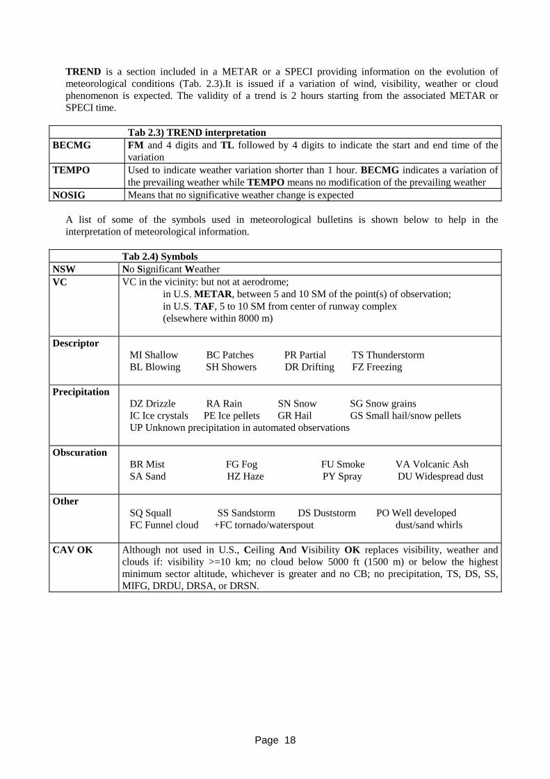
Page 18
TREND is a section included in a METAR or a SPECI providing information on the evolution of meteorological conditions (Tab. 2.3).It is issued if a variation of wind, visibility, weather or cloud phenomenon is expected. The validity of a trend is 2 hours starting from the associated METAR or SPECI time.
Tab 2.3) TREND interpretation BECMG FM and 4 digits and TL followed by 4 digits to indicate the start and end time of the
variation TEMPO Used to indicate weather variation shorter than 1 hour. BECMG indicates a variation of
the prevailing weather while TEMPO means no modification of the prevailing weather NOSIG Means that no significative weather change is expected
A list of some of the symbols used in meteorological bulletins is shown below to help in the interpretation of meteorological information.
Tab 2.4) Symbols NSW No Significant Weather VC VC in the vicinity: but not at aerodrome;
in U.S. METAR, between 5 and 10 SM of the point(s) of observation; in U.S. TAF, 5 to 10 SM from center of runway complex (elsewhere within 8000 m)
Descriptor MI Shallow BC Patches PR Partial TS Thunderstorm BL Blowing SH Showers DR Drifting FZ Freezing
Precipitation DZ Drizzle RA Rain SN Snow SG Snow grains IC Ice crystals PE Ice pellets GR Hail GS Small hail/snow pellets UP Unknown precipitation in automated observations
Obscuration
BR Mist FG Fog FU Smoke VA Volcanic Ash SA Sand HZ Haze PY Spray DU Widespread dust
Other
SQ Squall SS Sandstorm DS Duststorm PO Well developed FC Funnel cloud +FC tornado/waterspout dust/sand whirls
CAV OK Although not used in U.S., Ceiling And Visibility OK replaces visibility, weather and clouds if: visibility >=10 km; no cloud below 5000 ft (1500 m) or below the highest minimum sector altitude, whichever is greater and no CB; no precipitation, TS, DS, SS, MIFG, DRDU, DRSA, or DRSN.

Page 19
2.4.2) SIGMETS AND AIRMETS
AIRMET In-flight weather advisories concerning phenomena of operational interest to all aircraft and potentially hazardous to aircraft having limited capabilities. AIRMETs are issued every six hours with amendments as needed and cover moderate icing, moderate turbulence, sustained surface winds of 30 knots or more, extensive mountain obscuration, and widespread areas of ceilings less than 1000 feet and/or visibility less than 3 miles.
SIGMET
In-flight weather advisory concerning phenomena of an intensity and extent that concerns the safety of all aircraft. SIGMETs cover severe and extreme turbulence, severe icing, volcanic ash and widespread dust or sandstorms that reduce visibility to less than 3 miles. CONVECTIVE SIGMETs advise of thunderstorms that are potentially hazardous to all aircraft. Information contained in SIGMETs depend on the cruise level:
Tab 2.5) AIRMET/SIGMET
At subsonic cruising levels At transonic level and supersonic cruising levels Thunderstorm (OBCS. EMBD, SQL, FRQ) - TS Tropical cyclone - TC (+cyclone name) Thunderstorm with heavy hail - TS HVYGR Severe turbulence - SEV TURB Severe icing and sever icing due to freezing rain -SEV ICE, SEV ICE (FZRA) Severe mountain waves - SEV MTW Heavy sandstorm/duststorm - HVY SS/DS Volcanic ash – VA (+volcano name)
Moderate or severe turbulence - MOD SEV TURBCumulonimbus clouds - (ISOL, OCNL, FRQ) CB Hail - GR Volcanic ash - VA (+volcano name)
2.4.3) PIlot REPortS (PIREPS) CODING FORMATS AND FIELDS
Given the location of icing forecast, the best method to determine the intensity of icing conditions is the interpretation of PIlot REPorts. Required elements for PIREPs are: message type, location, time, flight level, type of aircraft and weather element encountered. This system is very effective, but it is mainly used in the USA while it is not very used in Europe. PIREPs appear as UA (upper-air) or UUA (urgent upper-air) reports. Typically, icing PIREPs contain the location, time, altimeter setting, aircraft type, icing type and/or severity, and additional remarks. They may also contain reports of sky conditions, weather, temperature, winds, and airspeed. PIREPs can be exchanged between aircraft in flight to provide awareness of meteorological conditions, but they can also be distributed to meteorological service and help improve both the operational products (SIGWX charts, etc) and research on icing detection. Note: At the moment of this writing, substantial changes to the content of icing PIREPS are being
proposed by committees in both Europe and the USA. These changes may eventually replace the current formats, but in the meantime the currently accepted formats are reviewed in tab. 2.6.
Note the following with regard to PIREP codes:
• Icing type and severity fields are usually combined under "/IC" • Miscoding is common. Icing type may be found in a turbulence report (/TB MOD MXD),
icing type of mixed may be "mxe" rather than "mxd" temperature may be ºF rather than ºC, etc.

Page 20
Tab 2.6) PIREPs decoding
Field Code(s) Units Examples Example Translations Report Type UA n/a UA Upper-Air
UUA UUA Urgent Upper-Air Location OV Nautical miles and degrees
magnetic north from a station /OV DEN 20 N 20 nm north of Denver
International Airport /OV DEN 360020 (Same)
Time TM UTC /TM 1315 1315 UTC Altimeter Setting FL 100s of feet MSL (This is a
'pressure altitude' value based on the ground altimeter setting and the altimeter equation.)
/FL070 7000 ft MSL
/FL100-120 10000 to 12000 ft MSL /FLUNKN Flight level unknown /FLDURC During climb /FLDURD During descent
Aircraft Type TP Coded /TP BE02 Beechcraft 1900 /TP B727 Boeing 727
Sky Conditions SK Usually, overcast cloud deck altitude
/SK OVC080
8000 ft MSL overcast
/SK BKN085 TOPS 220 Cloud base 8500 ft broken, tops at 22000 ft
Weather WX n/a /WX ZL- SFC-050 Freezing rain fromthe surface up to5000 ft
Outside Air Temperature
TA ºC /TA -20 -20 ºC
/TA 01 e 040 1 ºC @ 4000 ft Wind Speed and
Direction WV Radial direction and knots /WV 270022eFL050 22 kt from the west
at 5000 ft Indicated Airspeed
IAS Knots /IAS 200 200 kt
Icing Type IC Clear, mixed, or rime /IC CLR Clear /IC MXD Mixed /IC RIM Rime
Icing Severity IC Trace, light, moderate, severe /IC TRC Trace /IC LGT Light /IC MOD Moderate /IC SEV Severe /IC HVY Heavy (should be
interpreted as "severe") Remarks RM Free form with abbreviations /RM DURGC During climb /RM HYR LYR ABV Higher cloud layer above /RM IMC 030-090 Instrument meteorological
conditions (i.e., clouds or precip.) between 3000 and 6000 ft
/RM ¼" IN 10 MIN Accumulated ¼ inch of ice in 10 minutes
/RM LOST ICE 035 Exited icing conditions at 3500 ft
2.4.4) SIGNIFICANT WEATHER CHART
Significant weather charts can be high, medium or low level (SWH, SWM, SWL). Exclusively for Europe medium high significant weather charts can be found (SWM/H).

Page 21
Heights 1. On the SWH and SWM charts the heights are indicated in flight levels, top over base. When
the top or the bases are outside that part of the atmosphere to which the chart referes, xxx may be used.
2. On the SWL chart: i) the heights are given in feet or in meters above sea level; ii) the abbreviation SFC is used to indicate the phenomena at sea level. Model SWH and SWM – Charts for significant weather (high and medium level):
L = centre of a low system H = centre of a high system Scalloped line = demarcation of area of significant weather Heavy broken line = delineation of area of cat Thick solid line, bearing a wind arrow and a flight level number = jet axis with indication
of wind direction and speed in knots and height in flight levels Dashed line = height of the isotherm of 0 °C labeled in flight levels Flight level inside small rectangles
a) on SWH charts: tropopause height in determinal points b) on SWM charts: height on the 0 °C level in determinal points
Figures above arrows = speed of displacement of frontal system in knots Model SWL – Chart for significant weather (low level)
+ = position of the centers of pressure , value given in hectopascals L = centre of a low pressure H = centre of a high pressure Scalloped line = demarcation of significant weather Dashed line = height of the isotherm of 0 °C in feet or in meters Figures inside small circles = temperatures in degrees Celsius, reported only on the charts of
levels lower than flight level 185; proceeded by the plus or minus sign Figures inside small rectangles = altitude of the 0 °C level in feet or meters Figures above arrows = speed of displacement of frontal system in knots
Arrows and feathers
The arrows indicate direction; the number of feathers corresponds to the speed

Page 22
For a thorough understanding of meteo charts, it is important to have a knowledge of the basic symbols used in meteorological forecasting. These are reported below:
Tab 2.7) Weather chart main symbols Sky cover Wind Fronts Symbols
SKC: 0/8 5 knots clod front
rain
FEW: 1/8 – 2/8 10 knots warm front
Shower
SCT: 3/8 – 4/8 15 knots
thunderstorm
BKN: 5/8 – 7/8 20 knots stationary front
drizzle
OVC: 8/8 25 knots
snow
50 knots occluded front
hail
75 knots freezing rain
100 knots Turbolence fog
p.s. Shaft on direction wind is coming from
moderate turbolence haze
severe turbolence
moderate icing
CAT
clear air turbolence
severe icing
An example of medium high weather chart can be found in next page in in fig. 2.12.

Page 23
Clouds can be classified in vertical, low, medium and high. Vertical clouds:
Cumulonimbus (Cb) are of great vertical extent; they can extend from 2000 m to 10000 m above the ground, common in spring and summer afternoons and associated with showers, hail and thunder.
Low clouds:
Cumulus (Cu) are flat based clouds with a rounded top Stratus (St) are in layers, usually very low and associated with weak drizzle, rain or snow Stratocumulus (Sc) have a rounded top clouds and form a layer
Medium clouds:
Altostratus (As) are semi-transparent or opaque layers Nimbostratus (Ns). They form an overall sheet of gray clouds producing continuous rain or
snow (The base tends to be at 2000 -2500 m) Altocumulus (Ac) are in tufts with rounded and slightly bulging upper parts
High clouds (usually are ice crystal clouds in low temperature area):
Cirrus (Ci) are shaped as filaments or hooks Cirrostratus (Cs) are in a layer Cirrocumulus (Cc) are composed of very small elements Dense cirrus are very dense and occurring in patches
Fig. 2.12) Example of significant weather chart
Moderate icing From FL 120 to 430, moderate turbulence from 120 to infinity
Tropopause FL 450
High pressure centre
Low pressure centre

Page 24
Airframe icing occurs most frequently within convective clouds, cumulus or cumulonimbus (CU/CB) where ice build up can be very rapid. In these clouds the icing layer can be several thousand feet thick and a dramatic change of altitude will be required to avoid icing; it is better to avoid flying through these clouds, if possible, either by turning back or changing the route. Icing can also occur in thin layered clouds, especially during winter. During autumn, winter and spring an extensive sheet of stratocumulus (SC) may frequently form just below a temperature inversion, with temperature in the clouds between 0 and -10 °C. Such clouds may only be one to two thousand feet deep, but within the cloud layer, ice may build up very quickly. This icing can be avoided by descending below the cloud, provided there is sufficient height available above the ground, or by climbing above the cloud layer. In case of icing, it is very difficult to decide the best flight strategy. This depends on meteorological conditions and on the aircraft capabilities. If the pilot decides to climb over the clouds, he must verify if the aircraft weight increased by ice, the degraded aircraft performance and the height of cloud top can allow this manoeuvre. Pilot could decide for a descent, but in this case he has to verify that he is not in a classical freezing rain with thermal inversion (in this case an increase in altitude will result in an increase in temperature while a decrease in altitude could be associated with a decrease of temperature and a worsening of the icing conditions). Pilots should also verify if terrain allows a descent. If a pilot decides to fly just above the clouds he must remember that the cloud tops could quickly rise and that near the cloud tops water concentration is often very large.
2.4.5) SNOTAM
SNOTAM provides indication on runway contamination. Usually it is provided as a series of 8 figures:
AA B C DD EE ‘AA’: Runway number identification ‘B’: type of contamination ‘C’ extension of contamination ‘DD’ thickness of contamination ‘EE’ Braking action For decoding refer to specific documentation
2.4.6) WEATHER RADAR
The weather radar is generally used to detect thunderstorm and areas of strong precipitation and turbulence. Since a weather radar can detect precipitation, precipitation is usually associated to clouds, and clouds and moisture are the main factors for aircraft icing; a weather radar, if used in combination with other meteorological information (e.g. temperature), can provide valuable information for the identification of aircraft icing areas. A weather radar is based on the backscattering of radio-frequencies. The most used bands are:
Tab. 2.11) Radar wavelength
Band Frequency (Mhz) Wave length (cm) S 1550-3900 19.3 - 7.7 C 3900-6200 7.7 - 4.8 X 6200-10900 4.8 - 2.7

Page 25
The S band is used mainly for ground systems while X and C are used for on board systems (The lower the frequency, the greater the penetration capability but the lower the definition).
It is important to remark that a weather radar can detect mainly water particles or hail covered by water. Weather radar reflectivity from dry hail or snow is very low. Water molecules are dipoles that, when in a radar beam, are oriented in the direction of the beam and reflect the signal in the original direction. In the case of solid water (ice) the molecules cannot rotate and the radar signal is dispersed in all directions. Radar screens can be analog or digital. Analog indicators generate radar images slide by slide, in synchronization with the movement of the antenna (therefore of the radar beam). This is shown on screen by the movement of a subtle light trace. The digital weather radar screen shows the water concentration on a color scale; usually green represents low water concentration and red high water concentration. It is important to remember that a weather radar signal can be weakened by distance and by precipitation (a thunderstorm cell can hide clouds behind it). Another problem for a weather radar is that the signal can be confused with ground reflections. For this reason many radars are equipped with a ground clutter suppression system. Typically on board radars transmit a beam of about 3°. To detect clouds it is important to correctly select the radar beam inclination (TILT). During the descent, the tilt should be increased slowly upward to avoid ground interference. During takeoff the tilt should be initially set high and then slowly reduced to the value required during cruise.
RADAR PRECIPITATION
AREA
RED
AREA
VISIBLE PRECIPITATION AREA
NAUTICAL MILES
PR
ECIP
ITA
TIO
N
LEV
EL
Fig. 2.13) Weather radar principles

Page 26
A general rule is to lower the tilt until the first ground reflex appears and then to increase it a little. This is because the lower part of the clouds usually contains water and it can be more easily detected by radar. A radar should therefore be pointed as far down as possible. When correctly used and interpreted the radar can provide information on cloud location, intensity and an indication of the best route to follow.
2.5) Icing severity index
The environmental factors affecting icing are: liquid water content, temperature and droplet size. Cloud liquid water content (LWC) is the density of liquid water in a cloud expressed in grams of water per cubic meter (g/m3). LWC is important to determine how much water is available for icing. Even if LWC typically ranges between 0.3 and 0.6 g/m3, values as high as of 1.7 g/m3 can be found in cumuliform clouds. Temperature affects both the severity and the type of icing. Most icing tends to occur in the temperature range of 0 °C to -20 °C and the only physical cold limit is -40 °C because at this temperature droplets freeze even without icing nuclei.
Usually cloud droplets have diameters less than 50 microns. Nevertheless, sometimes, larger droplets from 50 to 500 microns (called freezing drizzle or freezing rain) can be found. These large droplets are usually defined as Supercooled Large Droplets (SLD) and represent a significant icing hazard since no aircraft has been demonstrated yet to fly safely in these conditions. Droplet size affects the collection of water drops by the airframe: small droplets tend to impact the airfoil near the leading edge while larger droplets tend to impact further back. SLD can be produced following two different processes. The warm-layer process and a collision-coalescence process. In the warm-layer process, ice falls through an above freezing layer of air where it melts forming drops. The drops then fall through a low-level freezing layer wherein they become supercooled and can reach the ground as freezing precipitation. In the collision-coalescence process, SLD form entirely in the low-level freezing layer and an initial ice phase is not needed. SLD tend to occur in areas where gradually lifting, shallow, saturated and relatively warm cloud tops (-12 °C) exist. Wind shear on the top of stratiform clouds is thought to be favorable to the formation of SLD. SLD aloft may be associated with freezing rain (FZRA), freezing drizzle (FZDZ) and ice pellets (IP) at the surface.
LEVEL 4
LEVEL 3
LEVEL 2
LEVEL 1
DISTANCE (NM)
PREC
IPIT
ATI
ON
INTE
NSI
TY (m
m/h
ours
)TH
UN
DER
STO
RM
INTE
NSI
TY L
EVEL
Fig. 2.14) Digital weather color scale

Page 27
Tab 2.12) Icing threat parameters Liquid Water Content (LWC) from 0. to 3 g/m3 Temperature from +4 ÷ +5 to -40 °C Droplet diameter (MVD) Usually from 0 to 50 micron, but also up to 300-400 microns
It is important here to note that the icing severity index used by pilots is different from the one used by meteorologists. Pilots use a classification based on the effect on the aircraft. Note: At the time of this writing, substantial changes to the content of icing severity index are being proposed. These changes may eventually replace the current formats, but in the meantime the currently accepted formats are reviewed here. Tab. 2.13) Pilots classification Icing Category Trace Ice becomes perceptible and barely can be seen. The rate of ice
accumulation is slightly greater than the rate of sublimation. Trace ice is not hazardous even without the use of de-icing/anti-icing equipment, unless the conditions are encountered for an extended period of time (over 1 hour)
Light The rate of accumulation of light icing may create a problem if flight is prolonged in this environment (over 1 hour). Occasional use of de-icing/anti-icing equipment removes or prevents its accumulation
Moderate The rate of accumulation of moderate icing is such that even short encounters become potentially hazadous and the use of de-icing/anti-icing equipment or a flight diversion is necessary.
Severe The rate of accumulation is such that de-icing/anti-icing equipment fails to reduce or control the accumulation. The only thing to do is conduct an immediate flight diversion.
It is clear that this classification is aircraft dependent. In the same area a B747 can fly without registering any ice accumulation (trace), while a small general aviation aircraft can register severe icing. The above classification is different from the one sometimes used by meteorologist which is reported in table 2.14 below.
Tab. 2.14) Meteorological classification
Icing Category LWC g/m3 Trace < 0.1 Light 0.11-0.6
Moderate 0.61-1.2 Severe >1.2

Page 28
Usually special symbols are used to define the severity of ice. Altitudes are usually reported on the right of the symbol in hundreds of feet. The upper number refers to the top of the icing conditions while the lower one refers to the base.
180 100
Light
180 100
Moderate
180 100
Severe
Fig. 2.15) Icing severity symbols

Page 29
3) PHYSICS OF ICE ACCRETION Ice accretion is usually caused by the freezing of supercooled water droplets on the aircraft surface. In real life clouds contain water droplets of various diameters and all the droplet diameters contribute to the ice accretion process; however, in order to be able to study and predict the physics of ice accretion the scientists agreed to define an average droplet diameter called Median Volumetric Diameter (MVD), expressed in micron (μm). A cloud, with all the water droplets having the same diameter MVD, will cause an ice accretion very similar to the one caused by an actual cloud with a range of droplets diameter having MVD as average diameter. The ice shape depends on the ambient temperature, the liquid water content, the droplet diameter, the flight conditions, the encounter duration and the aircraft geometry. The ice shapes are characterized by:
• Extension of the droplet impinging zone; • Shape and extension of ice • Texture of ice.
The extension of the droplet-impinging zone is bounded by the trajectories that droplets follow within the aerodynamic flow generated by the airfoil. In fact, droplet trajectories limit the impingement zone to SU on the upper surface and SL on the lower surface (Fig. 3.1).
The droplet trajectories and consequently, the extension of impinging zone are related to atmospheric conditions, aircraft velocity, airfoil shape, angle of attack and droplet diameter. In fact the trajectories of small dimension droplets are strongly influenced by aerodynamic flow generated by the airfoil and they tend to follow the streamlines, impinging only close to the airfoil stagnation point. Instead, the trajectories of larger droplets are less influenced by aerodynamic flow generated by the airfoil, and their trajectories tend to remain straight, impinging on a wider airfoil area.
The identification of the tangent trajectories allows the evaluation of the amount of water that impinges on the airfoil and that can change into ice. This quantity of liquid water is, in fact, defined by an important parameter called global collection efficiency (E). E can be calculated as ΔY0/ h , h being the height of the airfoil frontal section and ΔY0 being the distance between TU and TL measured far enough ahead of the airfoil for the flow to be considered undisturbed (TU is the droplet trajectory tangent to the upper airfoil surface, while TL represents the one that is tangent to the lower airfoil surface). From a physical point of view E represents the ratio between the rate of liquid water mass impinging the airfoil and the rate of water crossing an area as wide as the frontal airfoil section.
Fig. 3.1) Parameters characterizing droplet impinging on airfoil
Y
SU
SLh
U
TU
TL
ΔY0

Page 30
The collection efficiency depends on all atmospheric variables (except for the Liquid water Content, LWC, and the temperature), airfoil characteristics and velocity and angle of attack. It strongly increases when the droplets become larger and/or when the airfoil dimension becomes smaller. Furthermore, it increases weakly
when velocity and altitude increase. Therefore, by knowing E it is possible to know the liquid water rate, m.,
impinging on airfoil per span unity (U∞ is the asymptotic velocity [m⋅s-1]):
m. = LWC⋅E⋅U∞⋅h [g⋅m-1⋅s-1]
Increasing the aircraft exposure within the cloud, the total mass of liquid water captured by the airfoil increases.
Obviously, within a limited range of temperatures near the freezing value, the lower the air temperature, the bigger will be the liquid water mass which changes into ice; naturally, below this range only ice can be found, whilst above this range the water will not freeze at all. The water impinging on the aircraft surface can immediately freeze after impacting the aircraft surface or flow aft on the surfaces as run-back pushed by the aerodynamic forces as a thin film, rivulets or beads of water. A mass and energy balance causes the amount of water that freezes on the aircraft surface. To understand such as phenomenon we will consider a reference volume on the aircraft surface (Fig. 3.3).
Droplet20 microns
Droplet100 microns
streamlines
stagnationpoint
AIRFOILNACA23012
AIRFOILNACA23012stagnation
point
ice
ice
a)
b)
trajectories
Fig. 3.2-a) Droplets trajectories, diameter 20 microns, NACA 23012 airfoil; Fig.3.2-b) Droplets trajectories, diameter 100 microns, NACA 23012 airfoil.

Page 31
In figure 3.3 the rates of water mass which flow through a reference volume (control volume) are shown. The liquid water can enter the control volume by following two ways: coming from the supercooled droplets held in the air (m
.imp), or coming from an adjacent zone closer to the stagnation point (m
.rin). A water fraction
will freeze and increase the underneath ice layer, (m.
fre), another water fraction will remain at liquid state and will keep up flowing, (m
.rout). A third water fraction (m
.ev) will leave the control volume by evaporation
of water or by sublimation of the ice. The main energetic exchanges involved in the freezing process are convection, conduction, evaporation/sublimation/solidification latent heat. To describe the energetic balance a parameter called freezing fraction can be defined. The freezing fraction represents the amount of water that freezes and is equal to 1 if all the water is frozen (rime ice). The freezing fraction is between 0 and 1 if only part of the water freezes (glaze and mixed), and is zero if the water does not freeze at all. When the temperature is well below freezing, the freezing fraction is prevalent (freezing fraction close to 1) and ice formation remains bounded around the droplet-impinging zone on the airfoil. At higher temperatures, near freezing, the liquid water fraction is prevalent (freezing fraction close to 0) and water can flow along the surfaces even beyond the impinging area. This phenomenon, known as run-back, can cause ice formation in areas behind the impinging limits. The analysis of the shape and type of ice, which can develop on aircraft surfaces during the flight, shows as these characteristics also depend on the same parameters exerting an influence on the impinging zone, such as: atmospheric conditions, aircraft velocity, the airfoil shape and angle of attack. Changing these parameters, the mechanisms of ice accretion change and the following regimes can be individuated (Fig.s 3.4-3.7):
• rime ice, whitish and opaque ice formation • glaze ice, glassy, transparent or translucent and compact ice formation • mixed ice, characterized by both types of ice formation • step or run-back ice • frost
Fig. 3.3) Water mass involved in airfoil surface ice formation
mimp
mrin
mrout
mfre
liquid water film
mev
airfoil
supercooled droplets
U
zoom Control volume

Page 32
Rime ice Glaze ice (single horn) Glaze ice (double horns)
Figure 3.5) Rime and glaze ice shapes
Glaze and mixed ice Rime ice Run-back ice
Figure 3.6) Rime and glaze ice shapes
0.01 C 0.01 Ca) b)
Figure 3.4-a) Rime ice shape; Figure 3.4-b) Glaze ice shape.

Page 33
Supercooled droplets, freezing immediately after impinging the aircraft surfaces, cause rime ice and the ice formation remains within the impinging zone. The milky white color and the opaque appearance are given by the air that is entrapped between the frozen droplets. The rime ice formation process develops fast so that the ice accretion occurs over the impinging droplet points, creating rounded shapes on airfoil leading-edge.
Glaze ice results from droplets that do not freeze immediately but they join up by coalescence, creating bigger dimension droplets, rivulets or a thin liquid film on the aircraft surface. In these cases the air does not remain entrapped and the ice has a transparent appearance. Glaze ice accretion produces some irregular shapes, characterized by one or two horns generated by the run-back freezing. It is difficult to define correctly the relationship between atmospheric, meteorological conditions and ice shape because of the large and complex interaction between the involved parameters. For this reason rime and glaze typologies are considered as the two limiting situations whereas some intermediate situation can be expected. It is possible, in fact, to meet in nature atmospheric parameter combinations, which permit ice formations marked by rime ice characteristics in some zones, while, in others, by glaze ice characteristics. In this case the typology is called mixed or intermediate and it can be referred to both structural characteristics (density, color etc) and shape. Rime ice is typically accreted at low temperature, low values of LWC and droplets dimensions, while glaze ice is obtained at temperature closer to that of freezing (between 0° and -10°C) and for higher LWC values. The ice forming in intermediate layers of stratiform clouds is usually rime, while mixed formations can be present in the lower layers. Instead, ice formation is usually glaze in cumuliform clouds because of the higher LWC.
Fig. 3.7-a) Rime ice shape Fig. 3.7-b) Glaze ice shape.
Fig. 3.7-c) Frost

Page 34
We can refer to wind tunnel results on a NACA 0012 airfoil of 0,53 m chord, held for 8 minutes at 58 m/s, with LWC of 1,3 g/m3 and droplets diameter of 20 µm to provide an example of effects of temperature on ice shape. From T= - 2 C° to T= - 8 C° ice formation is completely glaze; at T= -18 C° half of the ice is glaze and half is rime; finally at T= -26 C° the whole ice formation is rime.
At the end of this paragraph it is important to describe the main features of SLD ice formation. As we have already observed, the SLD are large dimensions droplets at supercooled state and they involve an impinging zone larger than that obtained in the worst FAR/JAR 25 Appendix C conditions. Therefore, since ice protection systems are designed to be effective for environmental conditions defined within the Appendix C, in SLD conditions ice can accumulate after the area protected by the ice protection system. In this conditions, ice protection system activation (pneumatics boots) will eject the ice accumulated on the boot surface but will leave the ice behind the boot that can increase in size and form a ridge (step ice).
Another characteristic is represented by the usual presence of SLD at temperatures close to 0° C: such conditions will generally cause the run-back phenomenon. Therefore SLD are usually associated with run-back . Both these two characteristics involve ice formations that can extend beyond the zones commonly protected by de-icing and anti-icing systems and therefore they are able to reduce strongly the airfoil aerodynamic performances.
Ice accumulation behind the protected area is caused not only by SLD, but can occur also on aircraft equipped with a non-evaporative thermal ice protection system. In this case the power of the ice protection system is not enough to evaporate all the impinging water. The non-evaporated fraction will therefore run-back and freeze later on the aircraft surface.
Finally a type of ice that must not be ignored is frost. Hoarfrost will form on surfaces exposed to the open sky on cold clear nights due to radiation cooling. Frost may form either on the aircraft on the ground or in flight when descent is made from below freezing conditions into a layer of warm, moist air. In this condition aerodynamic performances may be affected and vision may be restricted as frost forms on windshields and canopies. Frost formation should not be underestimated since, as will be shown later, even a small amount, like in general any kind of roughness caused by ice accretion, on an airfoil leading edge can change dramatically airfoil performances.

Page 35
4) AERODYNAMICS
Ice formations on aircraft surfaces modify the aircraft performances and handling characteristics. Throughout the years the experiences accumulated in flight in icing conditions allow us to identify some of the problems faced by aircraft during the various phases of flight:
• In all flight phases ice on aircraft pitot tubes and probes can give wrong instrument indications
and wrong engine pressure ratios that lead to wrong inputs to the Flight Management System. • In all flight phases ice can cause handling problems, decreases stall safety margins and can be
ingested by engines causing engine flameouts. • During take-offs we can observe the decreasing of climb rates and the increasing of ground rolls. • During cruise we can observe the decreasing of aircraft velocity, efficiency and ceiling height
associated with an increasing of fuel consumption and an alteration of trim characteristics. • During the approach or landing phase the ice on the tail can cause the tail stall with the resulting
probable loss of the aircraft.
The problems, that we have briefly listed above, arise because an iced airfoil usually is characterized by a lift and stall angle decrease and a drag increase. These effects are more perceived in small transport aircraft than in large aircraft. In fact, small airfoils are characterized by higher values of global collection efficiency E, and consequently by a larger impinging zone and a larger amount of collected ice relative to the airfoil size. In figure 4.1 is reported a typical example of this phenomenon. Two airfoils, having the same shape but different chord (0.5 and 1.5 meters), have been exposed at the same icing conditions. It is clear how, comparing the non-dimensional airfoils (fig 4.1-b) the accreted ice shape is more severe for the smaller airfoil. The modification of the airfoil shape is the main effect produced by ice while the weight increase is a secondary phenomenon, at least for commercial aircraft.
Fig. 4.1-a) Dimensional ice shapes Fig. 4.1-b) non-dimensional ice shapes

Page 36
4.1) Ice effects on airfoil performances
Ice accumulation can be considered a stochastic phenomenon. Ice shapes are affected by aircraft geometry and flight conditions, by atmospheric conditions and exposure time. Therefore, not only are ice shapes difficult to predict, but also their effects on the aircraft are not easily predictable. It is therefore impossible to define general rules to classify the effects of ice on aircraft. Nevertheless, in figure 4.2 some icing wind tunnel test results are reported: these were obtained on a typical commercial airfoil and, far from providing general rules, can provide an indication of the kind of performance degradation that could be encountered while flying in icing conditions.
In particular, for this specific case have been remarked:
• An important decrease of CLmax; the maximum decrease of CLmax is about 40% for glaze ice, while it is about 20% for mixed ice.
• Rime ice formation causes CLmax decreasing of about 10%. • Rime ice formation causes a relevant drag increase as in the cases of glaze and mixed ice. • A relevant decrease of the stall angle which is reduced by 5° for glaze ice and about 2,5° for mixed
ice.
Fig. 4.2-a) Lift coefficient, Cl , versus angle of attack for clean airfoil and for glaze, rime, and mixed ice Fig. 4.2-b) Drag coefficient, Cd,, versus angle of attack for clean airfoil and for glaze, rime, and mixed ice
Fig. 4.2-c) Moment coefficient, Cm , various the angle of attack for clean airfoil and for glaze and rime ice
-5 0 5 10 15 20 25
2.01.81.6
1.41.2
0.8
0.2
0.0
0.4
1.0
Rime
GlazeMixed
Clean
-5 0 5 10 15 20 25
0.5
0.4
0.3
0.2
0.1
0.0
GlazeMixedClean
CdCl
a) b) -5 0 5 10 15 20 25
c)
0.05
0.00
-0.05
-0.10
-0.15
Rime
GlazeMixed
Clean
Cm
lift c
oeffi
cent
,
drag
coe
ffice
nt,
mom
ent c
oeffi
cent
,
angle of attack (deg.)α
angle of attack (deg.)α
angle of attack (deg.)α
Rime
Mixed
Glaze

Page 37
• A relevant increase of the drag coefficient, which, for both ice types is about four or five times greater than that of the clean airfoil.
• A relevant variation of the pitching moment coefficient gradient that causes a reduction of the airfoil stability.
It is extremely important to point out that the previous data are presented only to give the reader actual numerical values found on wind tunnel tests for a specific airfoil profile and for a specific type of contamination. By no means such values should be used to retain the idea that a type of ice is less dangerous than another type as, generally speaking, in real life the pilot will not have the chance to assess the type of ice, the accretion rate, the thickness, the shape of the ice accretion that is contaminating his aircraft and therefore should be treating all the types of ice formation with the same caution. Another ice formation which is really dangerous for airfoil performances is hoar frost: a crystalline thin ice layer with a very rough surface formed by moisture condensation upon surfaces which are generally colder (at temperature lower than 0 °C) than the surrounding air. The hoar frost formation upon airframe can occur, thus, both on the ground and in flight when the aircraft, coming from a zone with a mean temperature lower than 0 °C, meets an hotter and humid air mass. This kind of ice is dangerous because of its rough surfaces, which near the leading edge cause a relevant decrease of suction of the wing with consequent lift decrease. The results of some wind tunnel tests, simulating hoar frost on airfoil leading edge (Fig. 4.3), showed a relevant reduction of CLmax and stall angle, respectively of 20% and about 3°, with roughness which is typical of the initial ice buildup (ratio between roughness height and airfoil chord, h/c, equal to .00007). Instead CLmax and stall angle decrease respectively about 33% and 5° with bigger roughness which is typical of the residual ice remaining after the aircraft de-icing system activation cycle (h/c = .00053).
If, instead, we consider an airfoil with a high lift leading edge device (slat), performance degradations are less severe with a CLmax reduction of 5% for the smaller type of roughness and of 10% for the larger, while the stall angle reduction remains in the range of 3° to 5° for both roughness. This means that aircraft without leading edge devices are more sensitive to leading edge contamination such as that caused by ground icing.
What we have observed up to now allows the understanding of the behavior of an airfoil on which ice accretion is obtained by exposing the airfoil itself to a specific atmospheric condition for a given interval of time. It is evident, however, that, all the other icing parameters being constant, the iced zone is subject to relevant changes during the exposure time .
The rime and glaze ice shapes obtained with four different exposure times are shown in figures 4.4 . In both cases it is possible to note how the ice amount accumulated on the airfoil increases with time; in particular horns dimensions of glaze ice shapes increase. On the other hand, we can observe how the extension of airfoil iced zone remains nearly unchanged.
Fig. 4.3)Lift coefficient, Cl, variation with the angle of attack for clean and frost contaminated airfoil;
the rough surface has been put on the upper surface up to the 6% of chord and on the lower surface up to
the 7,5% of chord
-4 -2 0 2 4 6 8 10 12 140.0
0.20.4
0.6
0.81.0
1.2
1.4
1.6
1.8
Cl
lift c
oeffi
cent
,
cleanh/c = 0.00007h/c = 0.00053
0.06c
0.075c

Page 38
Some tests have been carried out in an icing wind tunnel in order to understand airfoil performance degradation with time in a given atmospheric condition. In these tests the performances of two airfoils have been analyzed; one was the tail airfoil of a typical modern commercial transport aircraft and the other one was a wing airfoil of a typical modern Business Jet aircraft (Fig.s 4.5 and 4.6).
0.01 C
a)
b)
6 min.12 min.18 min.
2 min.
6 min.12 min.18 min.
2 min.
0.01 C
Fig. 4.4) Growth of ice shape varying the time: a) Rime; b) Glaze
0 5 10 15 200.05
0.06
0.07
time (min.)
0.55
0.50 5 10 15 20 25
lift c
oeffi
cent
,
lift c
oeffi
cent
,
0.11
0.10
0.09
0.08
0.7
0.65
0.6
Cl
Cl
Commercial TransportAirfoil (tail)
Business JetAirfoil (wing)
time (min.)a) b)
Fig. 4.5-a) Variation of lift coefficient, Cl, with time, for a tail airfoil of a typical modern commercial
transport aircraft in icing conditions Fig. 4.5-b) Variation of lift coefficient, Cl, with time, for a wing airfoil of a typical modern Jet
Business aircraft in icing conditions

Page 39
It is interesting to remark how for both airfoils the Cl shows an important reduction mainly at the beginning, then stabilizes later on constant values while the Cd shows a continuos increase with time.
4.2) Ice effects on handling characteristics
Lift reduction, drag increase, stall angle reduction and pitching moment anomalies, observed in icing conditions, are the direct consequence of pressure distribution alteration caused by ice. The modified pressure distribution can also influence stick forces and the efficiency of aerodynamic controls, by causing some problems to the aircraft handling and endangering flight safety. The difference between upper and lower surface pressure coefficients is qualitatively shown in figures 4.7 and 4.8 for an airfoil at positive incidence.
Fig. 4.7) Qualitative trend of difference between upper and lower surface pressure coefficient, ΔCp, for two different angles of attack, α;
time (min.)
Commercial TransportAirfoil (tail)
Business JetAirfoil (wing)
0 5 10 15 20
0.12
0.10
0.08
0.06
0.04
0.02
Cd
drag
coe
ffice
nt,
time (min.)0 5 10 15 20 25
0.00
0.14
0.12
0.10
0.08
0.06
0.04
0.02
Cd
drag
coe
ffice
nt,
0.00
a) b)
Fig. 4.6-a) Variation of drag coefficient, Cd, with time, for a typical modern commercial transport aircraft tail airfoil in icing conditions
Fig. 4.6-b) Variation of drag coefficient, Cd, with time, for typical modern Jet Business aircraft wing airfoil in icing conditions

Page 40
We can observe (Fig. 4.7) how the movable surface presents a suction force which increases when the angle of attack, α, increases. This force generates a moment around the hinge axis, which tends to turn the moving surface trailing edge up. This hinge moment (Mh, or the corresponding hinge moment coefficient Ch) is generated by the forces (F1 or F2) acting on the moving surface and is conventionally considered positive when it tends to turn the moving surface down (Fig. 4.9). When the moving surface is turned down (positive δa) the suction force increases and the hinge moment tends to push the moving surface to its original position (Fig. 4.8). Instead, when the moving surface is turned up (negative δa), the suction force decreases until it becomes a compression force generating a positive hinge moment pushing the moving surface back to its original position.
Fig. 4.8) Qualitative trend of difference between upper and lower surface pressure coefficient, ΔCp, for two different deflections of the moving surface, δa.
Fig. 4.9) Conventional sign for angle rotations of aileron, δa, and for hinge moment, Mh
α+δa+M +h
Ca
ΔCp
ΔCpMh2 > Mh1
δ1 > δ2
Mh1Mh2
δ1 δ2

Page 41
The variation of hinge moment coefficient can be summarized with the plot of Ch versus δa at a given α(Fig. 4.10). For a conventional airfoil flying at positive angle of attack and turning down the moving surface (positive δa), the Ch value remains always negative and increases in magnitude when α and δa increase. Flying with positive angle of attack but now turning up the moving surface (negative δa), Ch value is initially negative but it decreases in magnitude as δa increases, until, at a certain value of δa , Ch becomes positive. Concluding, usually the effect of α and δa variation is to generate a force that pushes the movable surface back to its neutral position.
This is not always the case if the airfoil is iced. Usually a leading edge separation bubble characterizes the airflow over an iced airfoil. The extension of the bubble on the upper surface is increased as the angle of attack increases while on the lower surface is decreased as angle of attack increases. The effect is a modification of pressure distribution also on the trailing edge zone with consequences upon the moving surface behavior in addition to the changes on lift, drag and stall angle already mentioned.
From the results of some tests carried out in wind tunnel with a NACA23012 airfoil, it is possible to observe how ice changes the aircraft behavior.
Fig. 4.10) Qualitative trend of hinge moment coefficient, Ch,, versus ailerons deflection, δα, at given angles of attack, α.
Ch
δa
α = -2°α = 0°
α = 2°α = 4°
+-
+
-
Fig. 4.11) Separation bubbles on an iced airfoil, varying the angle of attack, α.

Page 42
For δa = 0°, on the clean airfoil (Fig. 4.12), initially the Ch value decreases gradually when the angle of attack increases up to near the stall where an abrupt Ch decrease can be registered. Ice changes this trend. In fact, the abrupt variation of Ch value is recorded at lower angles of attack. We can note how the Ch value increases in magnitude at 8° angle of attack up to three times the expected clean airfoil values when an ice step, 6,35 mm (0,25”) high, is put at 2% of chord. Ice, therefore, can cause a strong increase in the hinge moment pushing the moving surface up from its neutral position.
The position of ice formation plays an important role in the hinge moment modification. In fact, moving back the ice step along the airfoil upper surface it is possible to find a position such that the abrupt reduction of Ch value occurs for a minimum value of the angle of attack. It is possible to note that the critical angle of attack is about 1° for an ice step placed between 10% and 20% of chord. Besides, the variation of Ch slope also can cause inversions of hinge moment signs. In fact we can observe how, for the airfoil at the conditions given in fig. 4.12, the Ch positive value, expected for the clean airfoil at about 3° angle of attack, becomes negative and remarkably bigger (in magnitude) when ice occurs. Therefore, ice can cause an opposite hinge moment trend and this phenomenon is called “hinge moment inversion”.
Hinge moment variations, described above, result in remarkable changes of stick forces. Typically this phenomenon can be caused by SLD. We have already observed how in SLD conditions the icing formation involves a wider airfoil area, which often extends beyond that commonly, protected by de-icing systems. In fact, when the boots are operated ice is detached from the leading edge, while ice
Ch
α(°)
Fig. 4.12) Trend of hinge moment coefficient, Ch, varying the angle of attack, α,
for δa = 0°: ice step placed at 2%, 10% and 20% of chord

Page 43
accreted behind the protected surface remains creating a step quite difficult to see from the cockpit and quite dangerous for the adherence of the boundary layer in the trailing edge zone and for the effectiveness of flight controls.
The residual ice provokes a worsening of the airfoil performances. In particular the strong aerodynamic suction caused by the separated flow behind the ridge of ice in the aileron area can cause the aileron snatching. The effects of this phenomenon can be very dangerous as the accident happened to the ATR72, at Roselawn in 1994, can show. During this accident, in fact, a violent and uncontrolled deflection of ailerons, provoked by the ice presence behind the de-icing boots, caused the aircraft loss.
Fig. 4.13) Effect of de-icing boot activation in presence of ice formations beyond the commonly protected airfoil zones.
ice shape
de-icing boot activation
residual ice shape afterde-icing boot activation
boot
separationbubble

Page 44
5) ICE DETECTION Ice detectors are devices conceived to identify icing conditions. Ice detectors can be used to detect the beginning of ice accretion, to monitor ice accretion and to identify the end of icing events. An ice detector can be used as an advisory system or as a primary system. An advisory ice detector sends an advisory signal to the pilot for information only. The pilot has still the responsibility to detect icing conditions or the presence of ice (or other contaminants such as snow, slush,…) and to take the appropriate action as required by the Aircraft Flight Manual. A primary ice detector sends a signal reliable enough to be used as the only information necessary for the pilot to take a proper action. A primary ice detector can be used as part of a fully automated de/anti-icing automatic system. As a matter of fact the ice detector automatically activates or deactivates the ice protection systems according to the status of icing conditions. Furthermore, several advisory/warning lights (detection / no detection, protection system activated / not activated and failures) provide the crew with all the necessary information regarding system status.. Ice detectors can be classified as non-intrusive (Fig. 5.1) or intrusive (Fig. 5.2). An intrusive ice detector protrudes into the aerodynamic flow. The detector or its sensitive part is impinged by water droplets. These detectors generally sense ice formation on their sensitive parts and measure icing conditions characteristics.
A non-intrusive ice detector is flush mounted with the aerodynamic surface. However, ice detectors can also be classified in various categories according to their working philosophy.
Fig. 5.1) Non-intrusive ice detector Fig. 5.2) Intrusive ice detector

Page 45
According to the principle used to detect ice, ice detectors can be classified as follows:
5.1) Visual cues 5.2) Detection of icing condition 5.3) Detection of ice accretion 5.4) Aerodynamics performance monitoring 5.5) Visualization of surfaces 5.6) Remote detection of icing conditions 5.7) Detection beyond Appendix C 5.8) Ground icing detection 5.9) Other
5.1) Visual cues
The pilot is provided with visual cues (given by specific or not specific devices) to recognise ice conditions. Specific visual cues. They are installed on aircraft to accomplish a dedicated function :
• cylinders, flat plates or little airfoils outside the cockpit or at the leading edge of wings and air intakes. • tufts on upper wing surface, for ground icing. Their movement indicate they are not stuck by icing. • refractive plates or black painted surfaces on the upper wing surface for ground icing to detect ice, slush and snow deposits.
Non-specific cues: normally they consist of parts of the aircraft within the pilot's field of view:
• wiper arms or blades, • window frames, • engine intakes or propeller spinners, • any other parts which have been shown to accrete ice under specific conditions (side windows,
aft of protected surface, etc. …). The following kind of information can be extracted from these cues :
• beginning of ice accretion, • estimated ice thickness, • estimated ice accretion rate, • end of ice accretion if the cue is periodically de-iced.
Visual cues can be used to identify icing conditions severity and the action to be applied in conformity with the flight manual procedures (for activation of the various ice protection systems). Visual cues can be used to verify that ice is no longer accreting on the aircraft. Visual cues can also be used to identify particular icing conditions (supercooled large droplets, or ground icing). For example, ice accretion on the side windows of ATR is a visual cue that identifies flight in supercooled large droplets. The main disadvantages of visual cues are that they are subjective and, therefore, require a good pilot training.
5.2) Detection of icing condition
Such detectors are intended to detect icing conditions in flight and provide the crew with the related ice indication or automatically activate de/anti-icing systems whenever the aircraft is flying in icing conditions that accrete more than a specified thickness. These detectors are generally intrusive.

Page 46
Several types of intrusive detectors have been or are used :
• Vibrating probe (piezoelectric, magnetostrictive or inductive transducers) with measurement of the resonant frequency variation. This technology is now the most widely used on aircraft through Rosemount detectors.
Vibrating probe detector works on the principle of an axially vibrating rod probe whose natural frequency is known. As ice accretes on the probe, the natural resonant frequency decreases below a certain threshold. Once ice has been detected, the probe is heated to be de-iced; after cooling it is ready for a new measurement. Ice severity is determined by the cycle duration.
• Vibrating surface (through piezoelectric transducers) fitted on a probe end, with
measurement of the stiffness variation of a membrane. Such a system developed by Vibrometer is being certified on the Dash 8-400.
This sensor works on the principle of a diaphragm or a disc exposed to icing so that when ice accretes on the diaphragm its stiffness increases causing the natural frequency to increase. The diaphragm is forced to oscillate by a piezoelectric material. The sensing diaphragm can be mounted flush or as a conventional finger probe.
• Scraper rotating on a surface with measurement of the torque required to rotate. A
torque increase up to a given threshold produces a warning signal.
Rotating disk is a disk exposed perpendicular to airstream. Ice is removed by a scraper. The torque required to remove ice is used to activate the warning system. This system can be affected by false warning caused by bugs or contaminants other than ice.
• Hot wires to measure the latent heat.
Hot wire ice detectors work on the principle that the transformation of ice into water takes place at constant temperature and that the resistivity of a conductor changes with the temperature. Typically, the detector has a thermal sensitive wire that is exposed to the airstream. The wire is subjected to a periodic current pulse which causes the wire to heat-up. If there is no ice on the wire, the resistivity will change linearly with time since the wire temperature changes. If ice has accreted, the temperature will remain constant at the melting point of ice and therefore the resistivity does not change. When all ice is turned into water, the wire resistivity will change again. The resistance is electronically sensed and an ice signal is sent. Once ice has been detected, the probe is de-iced, allowed to cool down and ready for a new measurement. This system typically cannot measure ice thickness.
• Pitot tube to measure the differential pressure variation.
These devices sense a decrease in ram air pressure whenever ice accretes over a row of holes drilled into the leading edge of a small strut (usually a large one and a set of small ones). A differential pressure sensor monitors the ram pressure difference between the large hole and the set of small holes. In the absence of any ice accretion the ram pressure is balanced. Any ice accumulation on the strut will block the small holes first and will result in an unbalance of ram air pressure.
• Obstruction of a beam (visible light, laser, electromagnetic, infrared or nuclear beam)
between a transmitter and a receiver.

Page 47
Light beam interruption ice detectors operate on the principle that ice accreted on a probe occludes a light beam crossing the central area of the probe at an oblique angle with a light sensitive receiver placed on the opposite side. When the light occlusion reaches a certain level a heating cycle is initiated to remove ice. The cycle duration determines the amount of ice.
The first two technologies are recent applications; the others are being progressively abandoned. Using the above technologies ice conditions can be detected but not actually identified. Most of these detectors can provide a signal correlated with an accretion rate based upon their sensitivity but they cannot detect how much ice the aircraft critical surfaces are collecting. These systems can be used for detection of ice conditions, activation of ice protection systems, application of specific procedures for the flight in icing conditions, detection of the end of icing conditions and for systems deactivation. Some detectors may include a heating element to de-ice the strut and/or the sensing element after an ice detection is provided at a given threshold. This allows the detector to initiate a new detection cycle. For normal icing conditions, the time to de-ice the sensor is negligible when compared with the time to get an icing signal. Then the number of elementary detection is assumed to be proportional with the accretion rate or the icing severity. However for icing conditions characterized by high liquid water content, the time to de-ice is no more negligible when compared to the time ice accretion will take to reach the given threshold. Therefore in such a case any implication concerning icing severity would be inconsistent.
5.3) Detection of ice accretion
Such detectors are intended to detect any ice which forms on a specific surface, such as, the leading edges of wings, engine inlets, cool air intakes and wing upper surfaces. They are operative for flight and/or ground icing and provide indications and/or automatically activate de-icing systems whenever the aircraft is within icing conditions that accrete ice to more than a specified thickness. These detectors are generally non-intrusive (flush mounted). The detectors are integrated and detect ice formation over their sensing surfaces. Some of them are able to measure ice layer thickness or to distinguish ice from other contaminants (water, slush, de/anti icing fluids,...). The following methods of detection are used :
• Vibrating surface (piezoelectric transducers ) with measurement of the stiffness variation.
This sensor works on the principle of a diaphragm or a disc exposed to icing such that when ice accretes on the diaphragm its stiffness increases causing the natural frequency to increase. The diaphragm is forced to oscillate by a piezoelectric material. The sensing diaphragm can be mounted flush or as a conventional finger probe or in a contoured non-intrusive flush design.
• Pulse echo ice detectors.
Pulsed ultrasonic waves emitted by a piezometric element travel through ice in a direction parallel to the transducer emitting axis. When the pulse reaches the ice/air interface it is reflected back into the ice layer. The echo is returned to the trasductor and the elapsed time is used to calculate ice thickness.
• Microwave ice detectors.
The microwave transducer consists of a resonant surface waveguide embedded flush in the surface on which ice accretes. The waveguide is made out of material having the same dielectric properties of ice. When ice accretes, the resonant frequency shifts downward in

Page 48
proportion to the ice layer thickness, The frequency shift is electronically related to ice thickness and it is used to calculate both icing rate and accumulated ice thickness.
Most of these detectors provide a limited sensing surface which does necessarily reflect the status of the whole surface to be monitored. These systems can be used for detection of ice conditions, for ice protection system activation and/or for application of specific procedures to fly in icing conditions. These systems can also be used for detection of the end of icing conditions, for system deactivation or for the end of the specific procedures for flight in icing conditions. These systems can also be used to monitor the ice protection system performance. These kind of sensors monitor a limited surface area. For ground icing application, a limited number of sensors may not be sufficient to monitor the whole wing surface. Then, ground icing conditions do not necessarily lead to homogeneous ice coverage (ice spots, slush, snow, superposed layers, …) which make a reliable detection difficult. However when installed on a protected area (such as wing leading edge), the ice detector system should have the same ice collection efficiency as the protected area.
5.4) Detection of Aerodynamic disturbance
The aerodynamic characteristics of an airfoil are modified according to the nature, the extent, the position and the thickness of any contamination adhering to its surface. Therefore, the monitoring of the aerodynamic performance would provide information on the airfoil status. • Measurement of the dynamic pressure at the stagnation line and static pressures on upper
and lower surface of an airfoil. Use of pressure measurements to compute coefficients homogeneous with Cd and Cl coefficients. Assuming a good calibration of such a system for a clean airfoil at each operational configuration, a warning is produced as soon as an abnormal variation of Cl or Cd is detected.
• Measurement of the static pressure within the boundary layer of an airfoil and of its level of
turbulence. Any contamination at the leading edge or on the upper/lower wing surface leads to turbulence. Assuming a good calibration of such a system for a clean airfoil at each operational configuration, a warning is produced as soon as an abnormal level of perturbation is detected.
Such a system, once installed on a widely calibrated airfoil, will be able to detect any abnormal contamination and effect (effectiveness decrease or failure of ice protection system or contamination downstream of protected area under ground icing or freezing drizzle/rain conditions). The limitation of this system is that any patch on the leading edge other than ice will be detected.
5.5) Visualization of surfaces
Direct visualization of critical surfaces through dedicated cameras with or without picture analysis (infrared imaging). These systems can be used for monitoring any surface which is not visible from the cockpit (wing upper surface, horizontal stabilizer, APU or air conditioning intake)
5.6) Remote detection

Page 49
This is an autonomous airborne icing avoidance system that, scanning in all directions, is able to early detect potential icing conditions. If potential icing conditions are detected, the system taking into accout weather conditions, aircraft aerodynamics and ice previously accreted on the aircraft, advises the pilot on how to avoid icing. Advice may and regard route and/or altitude changes. This technique is still at a research level and it is not operative yet. Research is directed to various technologies to individuate the one that is the more suitable to problem solutions:
1) Microwave radars are the most capable in detecting cloud droplets 2) Lidars can detect both droplet size distribution and liquid water content, but they have maximum efficiency at wavelengths that are not eye-safe. In addition, lidars show a range reduction in dense clouds where moderate to severe icing conditions may occur. 3) Radiometers can be used to measure temperature profiles and liquid water content. 4) Attenuation signals of a 2 band airborne radar.
Probably the most efficient way to perform remote ice detection will be the use of an integrated system of airborne radar, ground radar and satellite data. At present remote detection is very expensive and technologies are not mature yet for a commercial application. A lot of research however is going on in this area.
5.7) Detection beyond Appendix C
No aircraft has been tested to fly safely in conditions beyond Appendix C (Mean droplet diameter larger than 50 microns). Therefore it is fundamental for the pilots to identify and avoid these conditions. To help the pilot in recognizing such extreme conditions a number of visual cues have been identified:
• Unusually extensive ice accreted on the airframe in areas which usually do not collect ice (i.e. side window on ATR). • Accumulation of ice on the upper surface of the wing aft of the protected area. • Accumulation of ice on the lower surface of the wing aft of the protected area. • Accumulation of ice on the propeller spinner farther aft than normally observed. • Accumulation of ice on engine nacelle farther aft than normally observed.
In addition to these cues, signs which could indicate the presence of SLD are the following:
• Water splashing on windscreen at negative outside temperature. • Visible rain at negative outside temperature.
If one of these cues is seen by the crew, the evasive procedure, as defined within the Aircraft Flight Manual, must be applied.
5.8) Ground ice detection
5.8.1) Before de/anti-icing procedures
The first concern for the crew is to determine whether the de/anti-icing procedures need to be applied for a safe take-off. In order to supplement all the available visual cues such as refractive plates and tufts (fig. 5.3), various ice accretion sensors have been developed. Pinpoint (spot) sensors may be adequate to monitor limited critical areas with homogeneous ice formation (i.e. to address over the wing icing after cold soak), but they cannot identify the conditions of the whole lifting surfaces whatever the number of sensors might be.

Page 50
Even if a sensor shows a good reliability to detect any contamination (frost, snow, ice, as single or combined layers) it will not ensure that the aircraft surface in its immediate vicinity has the same ice contamination level. Although a tactile inspection, when possible, is always the best way to clear up any doubt, research is under way and the following systems are showing some promising results.
• BFGoodrich : HALO system. The wing skin is used to guide ultrasonic waves which are generated and received by transducers mounted beneath the surface. The system is able to detect and discriminate several contaminants according to the skin response. Several sensors (transducer/receiver) installed in a grid could cover and monitor the whole critical surface. On the other hand, aThe high number of components may be detrimental to the system reliability, moreover it has to be checked if the sensor response is not affected by wing load variations.
• Aerodynamic performance monitor. Licensed to BFGoodrich, this very powerful
system is able to detect any over wing contamination, provided it has been carefully calibrated on a clean airfoil. One sensor installed at the wing trailing edge can monitor up to 1m spanwise at the leading edge.
The system requires a minimum airflow in order to satisfactorily operate and it can only be used during the initial take-off phase. If a detrimental degradation is found during the initial take-off run, a warning must be produced well before V1. A high number of sensors are still required to cover the full span of the lifting surfaces.
• ID-1 from RVSI. Ground based or aircraft mounted cameras associated with specific
software for imaging treatment, allow for the detection of ice formation or snow deposits over the aircraft surfaces. The information is provided to the crew or the ground personnel through a screen.
The reliability of the system still needs to be investigated for all skin materials.
Again several cameras need to be installed on aircraft to monitor the various lifting surfaces. 5.8.2) After de/anti-icing procedures
When the duration of protection (after a de or anti-icing fluid application),indicated by special tables called Holdover Time Tables (annex 2), has elapsed or when the crew are in doubt about the intensity of precipitation a visual inspection will be carried out by the crew or qualified ground personnel. If a fluid failure (appearance of ice formation or loss of gloss) is detected or if the crew have any doubt about it, the aircraft shall receive a new de/anti-icing treatment. An
Fig. 5.3) Tufts used for ground icing detection
Page 51
efficient and reliable ice detection may be useful:
• To help the crew take a decision and enhance safety. • Not to perform a supplementary de/anti-icing procedure when unnecessary and then not
to delay the take-off any further. • To decrease fluid waste and runway contamination (poor friction coefficient). • For the ecological impact.
In addition to the detection technologies described above, some equipment manufacturers have developed means to monitor the fluid de-icing capability. The sensors are punctual and flush mounted to the surface.
• Techniques based on a Peltier device. The freezing temperature of fluid/water mixture is dependant upon the water ratio (the greater the amount of water the higher the freezing temperature). The surface of the sensor (vibrating membrane) is cooled with a Peltier device (cooled when electrically supplied) to get an ice signal. The freezing temperature is then compared to the ambient temperature. When the freezing temperature of the mixture is too close or above the ambient temperature, a warning signal is produced.
• Techniques based on ultrasonic waves. The fluid/water mixture provides different
signature to an ultrasonic wave according to the water dilution. For a given fluid, according to the ambient temperature, it is possible to predict for which dilution it will freeze. A warning signal will be produced when, according to the external temperature, the mixture is too close to freezing.
All these technologies are still under development and are far from a certification status as a primary device. It is also important to remark that, because of different fluid flow-off characteristics, according to the type of fluid, the loss of effectiveness may occur at different location of the wing. This, in addition to the fact that fluid coverage is rarely homogeneous, implies that the actual location in which the detectors are installed greately affect the system effectiveness.
5.9) Other indicators
The detection principles listed above are not comprehensive. Any other means, provided they have been validated, can be used by the crew. The following are known to be used :
• Wing aerodynamic buffet. • Vibrations on control stick. • Ice accretions on wing leading edge. • Performances reduction. • Noise due to ice shedding. This is mainly valid for ice accumulating on propellers. Ice naturally
sheds from the rotating blades due to centrifugal forces. So, as soon as ice is shed from the blades, ice slabs may impact the fuselage so announcing the presence of icing conditions. It could also be a clear evidence of the icing conditions or an indicator of the propeller ice protection system. If the outside temperature is very low or if the propeller de-icing is inactive (switched off or failed), the ice slabs will be larger (increase of the ice adhesion force) and a louder noise will be produced.
• Propeller imbalancing due to ice.
5.10) Cockpit indications
There are several methods to inform pilots about icing conditions. The most used method in a non-Cathode Ray Tube (CRT) type of cockpit is a ‘Master Caution Light’ in conjunction with other

Page 52
warning lights. This method is often used where ice protection system controls must be manually actuated. Other systems which automatically energize ice protection systems, merely report the presence of ice via a panel light or in some cases not at all. In a CRT type of cockpit a phrase such as ENGINE ICING or AIRPLANE ICING is used to alert the crew of an icing encounter. A fail signal is available on some ice detector units.
5.11) Ice detection summary
Method Typical Technology Classification Status
Differential Pressure Detection
Pressure Array Detectors Detection of icing conditions
Progressively abandoned
Obstruction Ice Detection
Light beam interruption; Beta beam interruption;
Rotating disk Detection of icing
conditions
Progressively abandoned
Vibrating Probe/surface Ice
Detection
Piezoelectric; Magnetostrictive; Inductive
Detection of ice condition, ice
thickness and ice accretion rate
The most used technology
Latent Heat Ice Detection
Periodic current pulse; Power Measurement
Detection of icing conditions
Progressively abandoned
Microwave Ice Detection
Resonant surface waveguide (dielectric)
Detection of icing conditions
In development
Electromagnetic Ice Detection
EM source (visible light, infrared, laser, nuclear beam) Visualization of
surface In development
Pulse Echo Ice Detection
Piezoelectric transducers Detection of ice condition, ice
thickness and ice accretion rate
In development
Remote sensing
On board radar, ground radar, satellite
Detection of icing condition in front of the aircraft to avoid
inadvertent icing encounter
In development

Page 53
6) ICE PROTECTION Ice protection systems are used to protect aircraft surfaces (airframe, engine inlets, airdata systems and windshield) from ice accumulation in flight or on the ground. The main classification of ice protection systems is between de-icing systems and anti-icing systems. De-icing systems remove ice from the contaminated surface. Therefore, de-icing systems are usually activated after icing conditions have been encountered. Anti-icing systems provide a protection from icing, and therefore they are usually activated just before or immediately after entering icing conditions. Various concepts are available for airframe and engine air intake protection: 6.1) Thermal (Bleed Air) Ice Protection
This type of system (Fig. 6.1) uses engine bleed air to heat the water droplet impingement region of the airfoil surface to prevent the droplets from freezing (anti-icing running wet), evaporate the droplets (anti-icing evaporative) or debond accreted ice (de-icing). A pressure and temperature controlled supply of engine bleed air is ducted to the areas requiring protection and is distributed along the leading edge of the protected surface via a perforated "piccolo" tube. The air is then ducted in a chordwise direction by nozzles and/or areas of double skin before being vented overboard. The system is usually used as anti-icing either in fully-evaporative or in running-wet mode. This system is effective and reliable, although very large amounts of bleed air are required, particularly for fully evaporative systems. This results in a loss of engine performance and an increased fuel burn which may cause significant performance penalties on the aircraft. The use of hot bleed air prevents the use of composite materials for wing leading edges and may limit the introduction of such materials also for other parts of the wing structure. With the introduction of high bypass ratio jet engines, it is becoming increasingly difficult to provide supplies of bleed air in the quantities available to earlier generations of jet aircraft. It has therefore become necessary, on some recent designs, to operate the system in a de-icing rather than an anti-icing mode or to significantly increase the bleed air control temperature (from around 200oC to between 300 oC and 400 oC), necessitating the introduction of more exotic materials for air supply ducts and leading edge skins. 6.1.1) Operation
Operation on the ground for checkout or calibration purposes can be conducted using an ambient temperature high pressure air source. System operation is controlled from the cockpit, usually by a simple ON/OFF control. Operation of thermal ice protection systems on the ground, or at low flight speed, can cause serious overheating problems. Normal bleed air source can be at a temperature of 230 °C (450 °F). Without ambient airflow over the external surfaces, these high temperatures could damage the aircraft skin, especially for evaporative systems.
Fig. 6.1) Thermal (Bleed Air) Ice Protection

Page 54
Proper system operation may be checked on the flight line by means of the valve disagreement lights, temperature and pressure warning devices, changes in EPR or NI when the system is turned ON, and by a pneumatic system switch point check (if applicable). Due to the greater requirements of such an ice protection system, often, the engine pressure level normally used for air conditioning is not sufficient and therefore, when such a system is switched on, the available airflow is increased to a higher level using extra bleed air from an higher compressor stage. This may be checked by setting the engine at the minimum EPR (or NI) for operation on a mid-stage bleed with ice protection OFF: when the ice protection is ON, the pneumatic system pressure will generally increase because of the change in switch point.
6.2) Electrothermal Ice Protection
Electrothermal systems (Fig. 6.2) use electrical heater elements embedded in the protected surface to either prevent impinging water droplets from freezing (anti-icing) or debond existing ice accretions (de-icing). The heaters may be constructed with wire conductors woven into an external mat, etched foil bonded to a carrier, conductive composite material or a sprayed metallic coating applied directly to the protected surface. Due to the high power requirements of electrothermal systems (approximately 10 - 12 watts/in2) their use is generally limited to small components or areas where other methods of protection are impractical. These include windscreens, pitot probes, drain masts, small engine intakes, propellers, helicopter rotor blades and remote areas of the airframe such as control surface horns. In order
to minimize power requirements, larger airframe surfaces generally utilize the concept in a de-icing mode with continuously heated breaker strips on the stagnation point and cyclically heated panels in areas further aft. 6.2.1) Operation
The system can be used both as anti-icing and de-icing. Anti-icing should be turned on as soon as icing conditions are encountered, de-icing systems have to be turned on after ice has started to accumulate on the protected surface. The system needs to be tested before flight. In some cases an annunciator light, in other cases the aircraft’s ammeter or power meter must be observed for reading changes when the system is turned on or off. The systems must be turned off when not required, to save energy and to avoid elements burning out on the ground. Typically when aircraft flies into conditions where the outside air temperature is below a certain value (0 C° to 4 C°) the system becomes armed. Manual on-time control can also be set by a pilot switch, although this would increase the potential for surface overheating.
Fig. 6.2) Electrothermal Ice Protection

Page 55
6.3) Pneumatic Boot De-icing
Pneumatic boot de-icing systems (Fig. 6.3) remove ice accumulations by alternately inflating and deflating tubes built into rubber mats bonded to the protected surfaces. Inflation of the tubes shatters the ice accretion and the particles are then removed by aerodynamic forces. The system requires a small flow of engine bleed air which is pressure regulated to typically 18 - 20 psig for boot inflation. A vacuum source is used to suck the boot onto the airfoil surface when the system is not in use. This type of system, which was first developed in the 1930s, requires very little power and uses simple, well proven technology. However, the boots are unsuitable for high performance aircraft and are prone to external damage and internal leakage, making regular replacement necessary. At ambient temperatures below -15 oC to -20 oC (5 oF to -4 oF) their ice shedding performance also deteriorates as the rubber becomes less flexible.
Actuation of the boots with thin layers of ice is said to result in "bridging" of the tubes when ice flexes as the tubes inflate and deflate rather than in being expelled. No direct evidence of "bridging" was found in recent years. It may therefore be a legacy of the past which persists despite the fact that the problem has been solved with the introduction of better materials. In particular, the increased air pressure of modern boot systems is probably able to cope with ice bridging. It has been proved that the only negative effect, in a modern boot system, of a premature activation of the boots is an increase in residual icing after a boot cycle; the increased residual ice is shed from the boots after 2-3 cycles of boots activation. Nevertheless the delayed activation of deicing boots has been the cause of some catastrophic accidents (Embraer Accident). Anyway, it is required that pilots strictly adhere to the aircraft manual for boots operations. Turbo-prop and piston engine commuters and light aircraft largely use pneumatic boots for airframe protection and electrothermal or bleed air systems for engine intake protection. Although pneumatic boots have a number of drawbacks, they are currently the only practical method available for the
Fig. 6.3) Pneumatic boot de-icing

Page 56
protection of the aircraft aerodynamic surfaces which do not have adequate quantities of bleed air available. 6.3.1) Operation
In-service problems with pneumatic boot systems result largely from pin holes in the boot outer surface and freezing of the distribution valves due to the presence of water. Attempts to solve the latter problem with improved water extraction and local heating of the valves have resulted in some improvements. Pneumatic boot de-icing systems are only suitable for lower speed aircraft which have insufficient engine bleed air available for hot air anti-icing. Whilst they have been perceived by many people to be unreliable and of limited capability, pneumatic boots do not appear to give significant problems in service. However, there are some maintenance penalties associated with the need to replace boots and solve problems related to water ingestion. When flying in icing conditions, pneumatic boots, being a de-icing system, cannot avoid some aircraft performance penalties because of the accreted ice before the system can be 'ON' and because of the residual ice remaining after the boots have deflated. Difficulties are also encountered in estimating the thickness of the accreted ice before the system can be switched 'ON'. Preflight checkout of the pneumatic boot de-icing system pressure and boot inflatation is recommended. As icing encounters and severity are difficult to forecast, a pilot should never depend upon marginal reserves of power or a partial efficient system when ice protection systems are supposed to be required. Air ambient temperature below -40 °C (-40 °F) may lead to permanent damage to the de-icing boots. A light is typically provided to illuminate a wing leading edge surface as an aid in observing ice accumulation during night operations. Liquids that reduce ice adhesion can be applied to boots prior to flight when an icing encounter is likely. These sprays reduce the adhesion of ice to the boot surface resulting in improved ice protection capability. However, the liquid erodes away so it must be replenished after 50 to 150 flight hours.
6.4) Fluid Ice Protection
The system operates on the principle that the surface that has to be protected is coated with a glycol based fluid which acts as a freezing point depressant (FPD) to prevent the accretion of ice. (Fig. 6.4) The system may be used in an anti-icing or a de-icing mode. The fluid is distributed on the surface that has to be protected by pumping it through porous leading edge panels made of sintered stainless steel wire mesh or laser drilled titanium sheet. A typical system consists of a fluid reservoir, suction and pressure filters and a number of proportioning units deviding the total pump flow to meet the requirements of the various protected surfaces. This type of system is relatively simple and uses well established technology with a low technical risk. However, unlike other systems, it has a finite endurance dependent on the amount of the fluid carried. The main penalty is the weight of the stored fluid, which would be considerable for a large aircraft.

Page 57
The use of this type of system has been limited, particularly in recent years, to light aircraft. 6.4.1) Operation
If icing-conditions are anticipated in flight, the system should be activated during the pre-flight inspection to ensure that the fluid is being delivered to the surface of each panel and/or windshield. This also has the function to prime the system. In flight, the system should be activated immediately prior to or upon entering icing conditions. This may be accomplished with the use of a visual cue or an ice detector. A pilot could be required to increase manually the flow rate in case of severe icing conditions or to remove quickly any significant amount of ice that may have accumulated due to an unduly late system activation.
6.5) Pneumatic Impulse De-icing (PIIP)
The PIIP system has been developed by the B F Goodrich company in the USA from the original pneumatic boot system. The system is intended to reduce aerodynamic degradation due to boot inflation, provide improved protection with thin layers of ice and provide a more resistant surface to erosion and damage. The system uses an electrically or hydraulically driven compressor to generate a high pressure air supply for tube inflation. Solenoid controlled impulse valves are activated by a controller to provide a pulse of compressed air to a series of small diameter spanwise inflation tubes located along the protected surfaces. The tubes are covered by a metallic or thermoplastic outer skin to provide resistance to damage or erosion. When the pressure pulse occurs, this outer surface deflects by a small amount (about 1 mm) with a very high acceleration, causing the accreted ice to be shed. Whilst this system requires limited power, a number of impulse valves and compressors have to be provided (one valve for about each 3 meters of protected surface). Recently small elements of the overall system have been tested in icing tunnels and on a test aircraft. Also, some of the components are still in the design or early development stages and today the use of the system still represents a significant risk.
6.5.1) Operation
Pre-flight checkout of the de-icing system, by means of a self-test mode, is recommended. The system is capable of operating within the temperature range of -55 °C to 74 °C (-67 °F to 165 °F). The system should be activated by selecting the AUTO cycle mode when icing conditions are known or expected. In this mode, the system will cycle continuously on predetermined, fixed-time basis, typically one-minute cycles, until the system is switched OFF. A MANUAL command may also be used to operate the system for one cycle “on demand”. There is no minimum or maximum ice thickness required for system operation. There is no reduced ice adhesion coating recommended and the use of paint on active surface is not recommended. Coating resistant to rain erosion could be recommended.
Fig. 6.4) Fluid ice protection

Page 58
6.6) Electro-Impulse De-icing (EIDI)
The EIDI (Fig. 6.5) system consists of a series of ribbon-wire coils rigidly fixed inside the protected surface, the outer surface of the coil being separated from the aircraft skin by a small air gap. The coils may be mounted off a spar or on a beam between the leading edge ribs. A high voltage pulse, typically 800 to 1,500 volts, is discharged through the coils, causing a strong electromagnetic field to form and then collapse, inducing eddy currents in the aircraft skin. The eddy current and coil current fields are mutually repulsive causing the aircraft skin to move and the ice to be de-bonded and expelled from the surface. In addition to the coils, which are spaced over the protected surface, the system consists of a power supply, storage capacitors and a program/controller unit. The capacitors discharge power through the coils when a silicon-controlled rectifier is remotely triggered to close the circuit. The system has low power requirements (2 to 3 Kw for an A320 size aircraft). Electro-Impulse De-Icing (EIDI) has been used in a production form on a number of Soviet airliners, and has been evaluated by many of the major European and US airframe manufacturers but it has not been adopted in the west yet. 6.6.1) Operation
A simple test can be performed on the ground by placing one’s hand on the leading edge skin as each coil fires. Tactile differences are evident for coils whose mounting has failed or whose circuit contains an electrical fault. An oscilloscope view of the current from the capacitor box may reveal changes in EIDI system physical geometry or electrical circuit faults. Test circuitry could be installed for in-flight checkout.
6.7) Electro-Expulsive De-icing (EEDI)
In the drive to produce new low power ice protection systems, EEDI (Fig. 6.6) was originally conceived by NASA and a development version of the system has subsequently been produced in the USA.
Fig. 6.5) EIDI: Electro-Impulse De-icing

Page 59
The system consists of a polyurethane elastomer blanket incorporating two parallel copper ribbon conductors. Pulses of electrical current are passed through the conductors and the opposing magnetic fields produce a high acceleration movement of the upper surface blankets which shatters and de-bonds the ice. The blankets are produced in long narrow segments which are butted together to protect larger areas. An outer surface layer is then applied to provide erosion and damage resistance, a smooth aerodynamic surface and assist uniform ice shedding across the butted segment joints. 6.7.1) Operation
System checkout is recommended and can be performed in two ways. The first is through the controller self-test mode. The second is very simple: placing one’s hand on the blanket surface to ensure that each blanket segment is firing. Also audible differences are evident for faulty segments. No minimum or maximum ice accretion is required; the system should be operated on visible moisture and ambient temperature below 10 °C (50 °F). A simple system may have merely a on/off power switch; complex systems may have an off/auto/manual-on/self tester selector plus a display of system status. In ON and AUTO mode the system will cycle continuously, in MANUAL mode the system will operate for one cycle “on demand”.
6.8) Ground de/anti-icing fluids
When winter climatic conditions result in ice deposits on aircraft stationed on the ground, take-off aerodynamic performances are compromised. The use of a mixture of hot water and glycol-based freezing point depressant fluids to de-ice aircraft is economical and viable but it provides a limited icing protection. Fifteen years ago, ground winter operations, in all major North American airports dealt essentially with deicing (Type I fluids short ice protection duration) and no anti-icing. Deicing operations are governed by a strict application of the clean surface rule: civil aviation regulation requires commercial aircraft to be free of ice, snow, or frost prior to take-off.
Fig. 6.6) EEDI : Electro-Expulsive De-icing

Page 60
To give an aircraft a reasonable amount of time before take-off, new procedures and fluids have been developed. These procedures make use of anti-icing fluids, which are currently designed to prevent ice formation for moderate (Type II fluids) and long (Type IV fluids) periods. In general anti-icing fluids exhibit a non-Newtonian behavior. While for Newtonian fluids viscosity is a function of temperature, for non-Newtonian fluids viscosity is a function of temperature and of shear forces. This means that while the aircraft is at rest, fluids have good viscosity and tend to remain on the aircraft surface. As the aircraft speed increases during take-off, shear forces increase on the fluid surface, causing a decrease in fluid viscosity that helps the shedding of the fluid from the aircraft. Experience however has demonstrated that Type II fluids used on performance limited aircraft greatly reduce their capabilities to produce lift at take-off. This is due to the fact that the relatively low rotation speed, required by those types of aircraft to become airborne, is not sufficient to blow Type II fluids off the aircraft at take-off speeds. Consequently, a new anti-icing fluid category has been introduced: Type III fluids. These fluids should still provide a significantly higher degree of protection than Type I fluids, but less than Type II fluids in order to allow a lesser viscosity and gain a better elimination under reduced shear conditions such as encountered for commuter aircraft (aircraft with rotation speeds significantly lower than the large jet rotation speeds which are 100 knots or greater). 6.8.1) Operation
FAR 121.629 ‘Operation in icing conditions’ states: ”No person may take off an aircraft when frost, snow or ice is adhering on the wings, control surfaces or propellers of the aircraft”. Before take-off the pilot must make sure that aircraft is free of ice. This can be done by a visual check, or in case of doubt, by passing one’s hand over the aircraft surface. Once the pilot has decided to de/anti-ice his aircraft before take-off, he has to decide the type of fluid to be used for the treatment. The liquids are often a mixture of hot water and glycol, and they are chosen using the “Hold Over table” as a function of the expected waiting time and the type and severity of the precipitation. Deicing and anti-icing procedures using freezing point depressant fluids can be performed in one or two steps. In case of one-step de-icing/anti-icing, the fluid used to de-ice the aircraft remains on the aircraft surfaces to provide limited anti-icing capability. Two step deicing/anti-icing consists of two distinct steps. The first step (deicing) is used to remove all frozen contaminants from all surfaces and components and it is followed by a second step (anti-icing) as a separate fluid application. Anti-icing fluid must be applied before the first step deicing fluid freezes and becomes ineffective (normally within 3 minutes).
Fig. 6.7) Example of ground ice treatment

Page 61
Note that ice can accumulate on an aircraft even if the external temperature is above zero. For example, a “wet wing” (wing with the fuel at direct contact with the aircraft external skin) could easily accumulate ice because the fuel acts as a heat sink cooling the external surface. Aircraft with rear mounted engines are very sensitive to ground icing: ice can detach from the wings or the fuselage and go directly into the engines, causing a decrease in power or even, in the most severe cases, engine flame-outs.
6.9) Ice protection summary
Turbo-jet Propeller-driven aircraft
Airfoil leading edges Engine bleed air, Pneumatic boots, Porous fluids panel
Pneumatic boots, Porous fluids panel
Engine air intakes Engine bleed air, Pneumatics boots, Electrical heater mats
Engine bleed air, Pneumatics boots, Electrical heater mats
Propellers Electrical heater mats, fluid systems
Windscreens Electrical heaters Electrical heaters Pitot-static systems Electrical heaters Electrical heaters Probes and drain masts Electrical heaters Electrical heaters Control surface horns Electrical heater mats Electrical heater mats

Page 62
7) EXAMPLES OF SYSTEM INTEGRATION 7.1) AP68TP-600 VIATOR
Aircraft model Aircraft Manufacturer
Aircraft weight Engine manufacturer
Engine model Engine power Engine type
Number of engines
AP68TP-600 VIATOR Partenavia 3000 Kg
Allison Division General Motors 250B17C+
328 shp Turboprop
2
This example is interesting because it is a typical case of an aircraft equipped with an ice protection system but not certified for flight in known icing conditions. The ice protection system is not powerfull enough to cope with ice accretion and it is only sufficient to give a pilot time to divert in case of inadvertent icing encounter. The aircraft is equipped with de-icing pneumatic boots on the wings, stabilizer and fin leading edge. The boots are pneumatically operated by engine-driven pumps. An annunciator light monitors the system operation. The deicing system is manually operated each time a de-ice cycle is desired. The switch will instantly spring back to OFF. The sequencing system inflates at the same time the tail section boots and the wing boots for approximately 6 seconds. The annunciator light will lit up when the boots reach a proper pressure. The pneumatic deicers should be activated when ice accumulates between 1/4 and 1/2 inch, but they must not be operated more than once per minute. Accumulation of ice larger than 1/2 inch can cause an increase in stall and buffet speed, and an increase in power is required to maintain cruise airspeed. Prestall buffet and stall speeds are increased also when boots are activated. Therefore, an increase in approach speed in icing condition is required. A pitot is installed on the left side of the fuselage and an electrical heating element is installed within the pitot tube to prevent ice obstruction. In addition to static source valves mounted flush on each side of the aircraft nose, an alternative emergency valve is located on the left side of the control pedestal. The aircraft is equipped with a compressor bleed air system that is manually operated by the pilot by pulling a knob located on the left hand lower section of the instrument panel. The knob actuates the deicing system on both engines simultaneously discharging heated air into the compressor inlet vanes. Use of the compressor ice protection system will increase T.O.T. of approximately 50 °C. The air intake is electrically heated, two switches are provided, one for each intake, on the "DE-ICE" panel located on the pilot side instrument panel. A press-to-test button is installed above the relevant air intake switch to provide advance warning of the deterioration of the insulation resistance within the de-icing heaters and protection against escalating damage. To test the system it is necessary to switch ON the battery, the air intake heating ant to press the test button. A green light will light up in the annunciator panel if the system is fully operational. When the test button is pressed again, the green light will go off. This action will also disconnect power from the heater elements until the system is reset by turning the air intake switch OFF. During air intake de-icing operation, an increase of 30 amps will be indicated in the relevant Volt/Ammeter. The propeller de-ice system consists of electrically heated mats on the propeller blades. Each mat consists of a heating element which receives electrical power through a de-icer timer. The timer provides power to all heating elements on one propeller for approximately 90 seconds, then the power is provided to all heating elements of the other propeller. An ammeter, with a green arc from 14 to 18

Page 63
amps is provided in the center left instruments panel to monitor operation of the propeller ice protection system. In case of inadvertent encounter of icing conditions (visible moisture and temperature below 5 °C) the following procedure must be followed:
a) Engine air intake ice protection switch ON b) Engine compressor inlet anti-ice knob PULL OUT c) Pitot heat CHECK ON d) Ignition ON e) Surface deicing AS REQUIRED f) Propeller ice protection switch ON g) Oil temperature MONITOR
De-icing boots must be off for take-off, during final approach and landing. Pre-flight inspection requires a check for tears, abrasion and cleanliness of de-ice boots; in addition a visual check of the boots functionality and of the “ON” annunciator light is required before take-off.
Aircraft performances are decreased if ice has accumulated on unprotected areas. It is required to maintain extra airspeed on approach to compensate for the increased prestall buffet associated with ice on the unprotected areas and the increased weight.

Page 64
7.2) ATR 72
Aircraft model
Aircraft Manufacturer Aircraft weight
Engine manufacturer Engine model Engine power Engine type
Number of engines
72 ATR
21500 Kg Pratt & Whitney Canada
PW 124/127 2160 - 2480 shp
Turboprop 2

Page 65
For this aircraft pneumatics boots have been installed on: wing leading edges, horizontal tailplane leading edges, engine air intakes and gas path de-icer. Electrical anti-icing is applied on windshield, probes, propellers, wing and horizontal and vertical tail horns. An ice detector is installed on wing mid-span and an ice probe, to be used as visual cues, is installed near the left wing. Three levels of ice protection are defined:
LEVEL I: all times. Probes and windshield heating is on. LEVEL II: in icing conditions. Electrical heaters are on for side windows, propellers, elevators, rudder and control surfaces horns. A minimum propeller speed must be maintained: (86% 4 blades, 82% 6 blades). Minimum speed must be increased and monitored. LEVEL III: ice accretion (visual cues or advisory system detection). All de-icing boots are activated.
An ice detection advisory amber light is installed in the cockpit. The amber light comes up if ice accretion is detected (.5 mm thickness on ice detector). The light is steady if horns anti-icing is on and is flashing if horns anti-icing is off. If horns anti-icing is off and/or airframe de-icing is off a caution light and an oral signal are activated.
The light goes off if ice is not detected for 1 minute.
A blue de-icing light is on when airframe de-icing system is on and is flashing if airframe de-icing system is on five minutes after last ice accretion detection. The aircraft is equipped with an angle of attack green push button. This button must be pushed in icing conditions to increase threshold stall warning. It is automatically selected when horns anti-icing is selected. To come back to normal stall threshold values horns anti-icing must be deselected and the button must be de-pressed.

Page 66
7.3) MD80
Aircraft model
Aircraft Manufacturer Aircraft weight
Engine manufacturer Engine model Engine power Engine type
Number of engines
MD-80 McDonnel-douglas 63505-72575 Kg
Pratt&Whitney Canada JT8D
18500-21000 lb st Jet 2

Page 67
The ice protection system consists of :
7.3.1) Windshield and window anti-icing; 7.3.2) Probe heaters; 7.3.3) Engine anti-ice; 7.3.4) Airfoil anti-ice and de-ice; 7.3.5) Wing upper surface ice detection devices; 7.3.6) Ice fod alert system; 7.3.7) Annunciator panel light system.

Page 68
7.3.1) Windshield and window anti-icing
This is an electrical system: it provides electrical heat for anti-icing to all pilots’ windshields. The system must be put manually on at least 30 min. before take-off regardless of weather conditions: in extreme cold temperatures it is recommended to turn it on even for a longer extent of time before departure.
7.3.2) Probe heaters
This too is an electrical system: it provides electrical heat for anti-icing to all statics, pitot tubes and angle of attack probes. The system is always on during take-off and for the rest of the flight, regardless of weather conditions.
7.3.3) Engine anti-ice
This is a hot air pressurized system from the two engine compressors. The system is totally manual and specifically designed to prevent ice formation. There are no specific sensors devoted to warn the pilot about the possibility of ice accretion; therefore the system is usually used as follows:
• On the ground, it must be put on when the OAT is < 6°C with a dew point within 3°C or with visible moisture;
• In the air it must be put on when the RAT is < 6°C with visible moisture or when ice conditions are forecast.
7.3.4) Airfoil anti-ice and de-ice
This is a hot air pressurized system from the two engine compressors through two pneumatic cross-feed valves. The system is totally manual and it consists of two parts: an anti-ice sub-system designed to prevent ice formation for the wing leading edge slats, forward strakes and for the air conditioned ram air scoop plus a de-ice sub-system designed to remove the ice on the horizontal stabilizer leading edge. Also in this case there is no specific sensor devoted to warn the pilot about the possibility of ice accretion; therefore the system is usually used as follows:
• Once airborne the anti-ice system must be used when the RAT is < 6°C with visible moisture or when ice conditions are forecast;
• The de-ice system must be used:
- every 20 min. in continuous icing conditions; - before switching off the airfoil anti-ice system; - approximately 1 min. before selecting land flaps.
7.3.5) Wing upper surface ice detection devices
It consists of a series of 4 triangular decals and tufts installed on each wing root. They are particularly helpful during ground operations: checking their freedom of movement will help during clear ice inspection.
7.3.6) Ice fod alert system
It is a fully automatic system designed to operate only during ground operations. A vibrating over-wing sensor located near the inboard aft corner of the main wing tank - in case of ice accretion during ground operations - will send a signal of possible ICE FOD on the annunciator panel.

Page 69
7. 3.7) Annunciator light system
An annunciator panel is provided for all conceivable malfunctions of ice protection systems. It comprises annunciator lights for:
- pneumatic failures: underpressure, undertemperature, overtemperature, ect; - electrical failures: heat sensor or windshield heat malfunctions; - ice fod alert system malfunction.

Page 70
7.4) B767
Aircraft model Aircraft Manufacturer
Aircraft weight Engine manufacturer
Engine model Engine power Engine type
Number of engines
B767 Boeing
179170-204120 Kg Pratt&Whitney – General Electric
PW4000 – 80C2 62100 – 63300 lb st
Jet 2
The ice protection system consists of :
7.4.1) Window anti-icing and anti-fog; 7.4.2) Probe heaters; 7.4.3) Engine anti-ice; 7.4.4) Wing anti-ice; 7.4.5) Wing anti-ice/Window/probe heat test switch; 7.4.6) Annunciator light system.
7.4.1) Window anti-icing and anti-fog
Such capacity is mainly provided by the electrical system: electrical heat is used for anti-icing and anti-fogging to all pilots’ windshields. However also air conditioned flow over the transparencies is used for maximum anti-fog efficiency. Furthermore the side windows are electrically heated, but for anti-fogging only. The systems must be on for every flight regardless of weather conditions.
7.4.2) Probe heaters
This too is an electrical system: it provides electrical heat for anti-icing to all statics, pitot tubes and angle of attack probes. The operation of the probe heat system is fully automatic and electrical power is applied to the probes whenever one engine is running.
7.4.3) Engine anti-ice
This is a system that uses hot bleed air from the two engine compressors. The system is controlled and activated from the cockpit by individual Engine Anti-ice switches and it is specifically designed to prevent ice formation. In order to prevent also the chance of flame out due to ice ingestion, the system has the capacity to automatically turn on the engine ignition whenever the anti-ice system is activated. There are no specific sensors devoted to warn the pilot about the possibility of ice accretion and therefore the system is usually used as follows: • On the ground it must be put on when the OAT is 10°C or below with a dew point
within 3°C or with visible moisture or when operating on ramps or taxiways where water may impinge and freeze on the air
intake exterior surfaces. • In the air it must be put on only with SAT ≥ -40°C when the TAT is 10°C or below,
with visible moisture or when ice conditions are forecast.

Page 71
7.4.4) Wing anti-ice
This is a hot air pressurized system from the two engine compressors through the pneumatic manifold. The system is totally manual and is controlled from the cockpit through a single Wing Anti-ice switch. Pushing the switch ON, a valve (electrically controlled and pressure actuated) in each wing is signaled to open and permit engine bleed air to heat the three outboard leading edge slat segments. Furthermore, an air/ground logic prevents wing anti-ice use during ground operations. The system is designed to prevent ice formation over the wing leading edge slats and should be used in the same manner as the engine anti-ice. Also in this case there is no specific sensor devoted to warn the pilot about the possibility of ice accretion over the wings. No installation is provided for tail anti or de-ice.
7.4.5) Wing anti-ice/Window/probe heat test switch
For pre-flight operation a three-position test switch, spring loaded to neutral, is provided to test the operation of the wing anti-ice valves and to test the functionality of the electrical system used for windows and probe anti-icing.
7.4.6) Annunciator light system
Various lights are provided for all the conceivable malfunctions of ice protection systems such as:
- pneumatic valve failures: valve position disagrees with switch position; - electrical failures: probe heat or windshield heat malfunctions.

Page 72
8) FLIGHT MANUAL SECTIONS CONCERNING ICE PROTECTION The Aircraft Flight Manual (AFM) is the primary source of information for a pilot. A pilot should always refer to AFM because each aircraft is different from the other, and even if some procedures might seem similar, essential differences could exist. Usually an AFM is basically structured in 9 sections even if the actual number of sections depends on the aircraft complexity. Anyway, generally speaking all the AFMs should contain the following chapters: GENERAL
Presents the basic aircraft data and general information which will be of value to the user.
LIMITATIONS Presents the operating limitations, the significance of such limitations, instrument markings, color coding and basic placards necessary for the safe operation of the airplane, its powerplant, standard system and standard equipment limitations.
EMERGENCY AND ABNORMAL PROCEDURES The recommended procedures for various types of emergencies and critical situations are provided in this section.
NORMAL PROCEDURES This section describes the recommended procedures to conduct the aircraft during normal operations.
PERFORMANCE This section provides performance information required by certification regulation that are useful for flight planning.
WEIGHT AND BALANCE This section contains the necessary information and procedures for correct loading and center of gravity calculation of the aircraft. This section also contains the procedures to establish the weight and balance for each flight and describes the moments arms and weights of all equipment installed on the aircraft at the time of the delivery. Weight and balance limitations, obviously, must never be exceeded.
A/C AND SYSTEM DESCRIPTION This section provides a description of the aircraft and its systems.
A/C HANDLING AND SERVICING This section provides information on handling, servicing, inspection and maintenance of the airplane. For complete maintenance instruction however see the Maintenance Manual.
SUPPLEMENTS This section consists of a series of supplements, each covering a particular operation in which the aircraft may be used or optional systems which may be installed on the aircraft.
The sections where the pilot can obtain all the information relevant to the flight in icing conditions are: - GENERAL - LIMITATIONS - EMERGENCY AND ABNORMAL PROCEDURES - NORMAL PROCEDURES
- PERFORMANCE - A/C AND SYSTEM DESCRIPTION

Page 73
9) EFFECT OF ICING ON AIRCRAFT Icing can affect aircraft performances and handling characteristics in different ways depending on the location, amount and kind of ice accretion. Therefore it is difficult to classify all possible effects of ice on aircraft. The following most common phenomena however can be stressed:
9.1) Wing stall 9.2) Icing contaminated tail stall (ICTS) 9.3) Icing contaminated roll upset 9.4) Ground icing 9.5) Engine and induction icing 9.6) Carburetor icing 9.7) Propeller icing 9.8) Instrument icing 9.9) Windshield
9.1) Wing stall
9.1.1) Description
Ice accretion on a wing has four main effects: lift and stall angle of attack decrease, drag and weight increase. The weight increase is usually not a major problem for commercial airliners; however, it can still represent a threat for performance limited type of aircraft. Of course, the main critical effect is the lift decrease. Even a small amount of ice on the wing leading edge can modify the wing lift-angle of attack curve. The main effect is a decrease in maximum lift coefficient and a decrease in stall angle. While ice can accrete on many airplane surfaces, discussion will focus on wing airfoil icing. There is an infinite variety of shapes, thickness and textures of ice that can accrete at various locations on the airfoil. Each ice shape essentially produces a new airfoil with unique lift, drag, stall angle, and pitching moment characteristics that are different from the host airfoil, and from other ice shapes. Various effects result from these shapes. Some effects are relatively benign and are almost indistinguishable from the host airfoil. Others may alter the aerodynamic characteristics so drastically that all or part of the airfoil stalls suddenly and without warning.
9.1.2) Avoidance
When flying in icing condition, it is very important to monitor speed and to maintain an increased margin from stall speed. Some aircraft are equipped with a system that automatically decreases the angle of attack at which stall warning is activated (usually when ice protection system is turned on).
9.1.3) Recovery
As for a classical wing stall, angle of attack should be reduced and speed should be increased. Since power may have a detrimental effect on wing stall due to icing, it must be applied with caution. Note that since ice accretion and/or ice shedding can be asymmetric, usually wing stall can be asymmetric too. In this condition a wing stall could be associated with severe uncommanded aircraft roll. In this case angle of attack decrease should be associated with appropriate aileron deflection to counteract the roll. The main difference with ice induced roll upset is that in case of a classic icing induced wing stall there should not be an aileron hinge moment anomaly even if in both cases there will be a sudden change in roll angle. In the case of a wing stall the change in roll angle is caused by an asymmetric stall, in the case of an ice induced roll upset it is caused by a sudden aileron movement due to flow separation. For both wing stall and ice contaminated roll upset, the recovery action consists in lowering the angle of attack. It is also fundamental to distinguish the induced wing stall from icing contaminated tail stall since in the
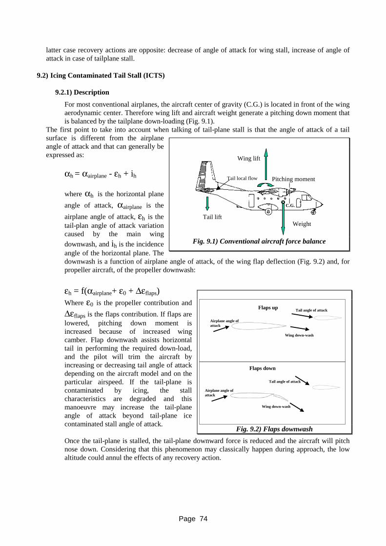
Page 74
latter case recovery actions are opposite: decrease of angle of attack for wing stall, increase of angle of attack in case of tailplane stall.
9.2) Icing Contaminated Tail Stall (ICTS)
9.2.1) Description
For most conventional airplanes, the aircraft center of gravity (C.G.) is located in front of the wing aerodynamic center. Therefore wing lift and aircraft weight generate a pitching down moment that is balanced by the tailplane down-loading (Fig. 9.1).
The first point to take into account when talking of tail-plane stall is that the angle of attack of a tail surface is different from the airplane angle of attack and that can generally be expressed as:
αh = αairplane - εh + ih where αh is the horizontal plane angle of attack, αairplane is the airplane angle of attack, εh is the tail-plan angle of attack variation caused by the main wing downwash, and ih is the incidence angle of the horizontal plane. The downwash is a function of airplane angle of attack, of the wing flap deflection (Fig. 9.2) and, for propeller aircraft, of the propeller downwash: εh = f(αairplane+ ε0 + Δεflaps)
Where ε0 is the propeller contribution and Δεflaps is the flaps contribution. If flaps are lowered, pitching down moment is increased because of increased wing camber. Flap downwash assists horizontal tail in performing the required down-load, and the pilot will trim the aircraft by increasing or decreasing tail angle of attack depending on the aircraft model and on the particular airspeed. If the tail-plane is contaminated by icing, the stall characteristics are degraded and this manoeuvre may increase the tail-plane angle of attack beyond tail-plane ice contaminated stall angle of attack. Once the tail-plane is stalled, the tail-plane downward force is reduced and the aircraft will pitch nose down. Considering that this phenomenon may classically happen during approach, the low altitude could annul the effects of any recovery action.
Tail liftWeight
Wing lift
Pitching moment
C.G.
Tail local flow
Fig. 9.1) Conventional aircraft force balance
Flaps up
Wing down-wash
Tail angle of attack
Airplane angle ofattack
Wing down-wash
Tail angle of attack
Airplane angle ofattack
Flaps down
Fig. 9.2) Flaps downwash

Page 75
In order to clarify the phenomenon we can refer to the figure where the tailplane lift coefficient versus the angle of attack for a clean and a contaminated tailplane (Fig. 9.3) is shown. When an aircraft is flying flaps up, the tailplane should be able, contaminated or not, to provide adequate download to balance the aircraft (Point A on the curve). However, when the flaps are lowered, the increased downwash (Δεflaps), will set the tail lift at point B if the tailplane is clear of ice, and at point C if the tailplane is contaminated. When flaps are lowered, additional negative lift is required by the tail, so the aircraft can be easily trimmed if the tailplane is clean (point B), but cannot be trimmed in case of contaminated tailplane because the tail is stalled and the tail lift (point C) is even lower than the lift generated in the raised flap configuration (point A). The result is a sudden nose-down aircraft attitude.
9.2.2) Identification
1) Stick movement similar to pilot induced oscillation can also be registered.
2) Control column buffet and not airframe buffet (caused by instationarity of separated aerodynamic forces).
3) a) Unpowered elevator: stick suddenly full forward. b) Powered elevator: an aircraft pitchdown tendency that is increased as the stick is pulled (i.e. elevator command
inversion).
9.2.3) Avoidance
1) Limit flap extension during flight in icing conditions. 2) Don’t use autopilot in severe icing conditions because it will automatically correct anomalies
that otherwise could be used as signals of ICTS identification. 3) Land at reduced flap setting and judiciously increase power. 4) Use ice protection systems as AFM suggests.
9.2.4) Recovery
1) Immediate raise flaps to the previos position and at the same time pull the yoke as required to recover the aircraft.
2) Use power sensibly (excessive power can aggravate the conditions since for some aircraft high power setting could adversely affect ICTS).
3) Land at reduced flap setting.
It is extremely important not to confuse tail plane stall with wing stall since recovery actions are exactly opposite. In tailplane stall, the flaps must be decreased and the yoke must be pulled full aft, in wing stall and roll upset yoke must be pushed forward. Such a difference is particularly vital for aircraft equipped with stick shaker and pusher. These devices can be very misleading: a shaker can appear to be the control column buffet characteristics of ICTS and the pusher can easily be mistaken for an elevator snatch associated with ICTS. Awareness of airspeed and flap deployment is extremely critical and must be used to interpret properly the various situations.
αtailplane
Δεflap
Lift coefficient tail
Clean airfoil
Iced airfoil
(A) Flaps- up(clean and iced airfoil)
(B) Flaps down (clean airfoil)
(C)Flaps- down (iced airfoil)
Fig. 9.3) Clean and iced tailplane lift coeffi
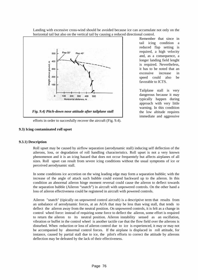
Page 76
Landing with excessive cross-wind should be avoided because ice can accumulate not only on the horizontal tail but also on the vertical tail by causing a reduced directional control.
Remember that since in tail icing condition a reduced flap setting is required, a high velocity and, as a consequence, a longer landing field lenght is required. Nevertheless, it has to be noted that an excessive increase in speed could also be favorable to ICTS. Tailplane stall is very dangerous because it may typically happen during approach with very little warning. In this condition the low altitude requires immediate and aggressive
efforts in order to succesfully recover the aircraft (Fig. 9.4).
9.3) Icing contaminated roll upset
9.3.1) Description
Roll upset may be caused by airflow separation (aerodynamic stall) inducing self deflection of the ailerons, loss, or degradation of roll handling characteristics. Roll upset is not a very known phenomenon and it is an icing hazard that does not occur frequentely but affects airplanes of all sizes. Roll upset can result from severe icing conditions without the usual symptoms of ice or perceived aerodynamic stall. In some conditions ice accretion on the wing leading edge may form a separation bubble; with the increase of the angle of attack such bubble could extend backward up to the aileron. In this condition an abnormal aileron hinge moment reversal could cause the aileron to deflect towards the separation bubble (Aileron “snatch”) in aircraft with unpowered controls. On the other hand a loss of aileron effectiveness could be registered in aircraft with powered controls. Aileron "snatch" (tipically on unpowered control aircraft) is a descriptive term that results from an unbalance of aerodynamic forces, at an AOA that may be less than wing stall, that tends to deflect the aileron away from the neutral position. On unpowered controls, it is felt as a change in control wheel force: instead of requiring some force to deflect the aileron, some effort is required to return the aileron to its neutral position. Aileron instability sensed as an oscillation, vibration or buffet in the control wheel is another tactile cue that the flow field over the ailerons is disturbed. When reduction or loss of aileron control due to ice is experienced, it may or may not be accompanied by abnormal control forces. If the airplane is displaced in roll attitude, for instance, caused by partial stall due to ice, the pilot's efforts to correct the attitude by ailerons deflection may be defeated by the lack of their effectiveness.
Fig. 9.4) Pitch-down nose attitude after tailplane stall
Page 77
9.3.2) Avoidance Typically (see ATR Accident) roll upset is caused by a ridge of ice forming near the aircraft leading edge. This ridge can form in SLD conditions (large droplet diameter). These droplets, having a larger inertia, can impact after the area protected by ice protection systems. In particular, if the aircraft is flying with flaps extended in SLD, an ice ridge can form on the aircraft upper surface. - The first rule is to avoid exposure to SLD icing conditions. - Be aware of the PIREPs and the forecast: know where potential icing conditions are located in
relation to the planned route and at which altitudes and directions you are likely to encounter warmer/colder air. About 25% of the cases of SLD are found in stratiform clouds colder than 0 °C at all levels, with a layer of wind shear at the cloud top. There need not be a warm melting layer above.
- Maintain awareness of outside temperature. Be sure of the freezing level (0 °C SAT). Be
especially alert for severe ice formation at a TAT near 0 °C or warmer (when the SAT is 0 °C or colder). Many icing events have been reported at these temperatures.
- In case of severe icing disengage the autopilot and hand fly the airplane. The autopilot may
hide important handling cues or may self disconnect causing the aircraft to take unusual attitudes.
Avoid holding in icing condition with flaps down: the flight with low angles of attack could cause an ice ridge formation on the upper wing. However, if the flaps have been deployed during flight in icing condition don't retract them: the associated increase in angle of attack could cause flow separation on the contaminated wing. (Follow airplane flight manual recommended procedures for holding). After the ATR accident, all turbopropops with unpowered controls have been screened by FAA to provide the pilots with some cues to help him identify SLD conditions. The major findings are reported below:: - Unusually ice accretion on areas where ice is not normally observed (e.g. side windows on ATR); - Accumulation of ice aft of the protected area; - Accumulation of ice on propeller spinner or on engine nacelle farther aft than normally observed; - Water splashing on windscreen at negative outside temperature; - Visible rain at negative outside temperature.
9.3.3) Recovery
Roll upset recovery can be performed by lowering the angle of attack. This is the only possible action. The decrease in angle of attack could provide a flow reattachment and a regain in control. - The angle of attack can be lowered either by lowering the aircraft nose, increasing airspeed or by
extending flaps. Lowering the nose is the preferred technique because it results in an instantaneous airspeed gain even if it causes a loss of altitude. Flaps extension is a secondary technique because the effect is not immediate, may cause further pitch excursions and may also have a detrimental effect on icing contaminated tail stall. However in the case of the EMB-120 in March 1998 flap deployment turned out to be the most successful way to recover the aircraft.
- If in a turn, the wings should be rolled level. - Set the appropriate power and monitor the airspeed and angle of attack.

Page 78
- If flaps are extended, do not retract them unless the upper surface of the airfoil is clear of ice,
since retracting the flaps will increase the AOA at a given airspeed. - Verify that the wing ice protection system is functioning normally and symmetrically through
visual observation of each wing. If there is a malfunction, follow the manufacturer's instructions.
- Change heading, altitude or both to find an area clear of clouds, or warmer than freezing, or
substantially colder than the current ambient temperature. - Advise ATC and promptly exit the condition using control inputs as smooth and as small as
possible. - When severe icing conditions exist, reporting them may assist other crews in maintaining
vigilance. Submit a pilot report (PIREP) of the observed icing conditions. It is important not to understate the conditions or effects.
9.4) Ground icing
The generally accepted principle of operation in adverse weather conditions is the “clean wing concept”. JAR-OPS 1.345 states that take-off shall not be commenced “unless the external surfaces are clear of any deposit which might adversely affect the performance and/or controllability of the airplane except as permitted in the AFM”. Manufacturers’ procedures in the AFM also state that aircraft must be clear of ice before take-off. In particular the pilot in command is responsable to verify that frost, ice or snow contamination is not adhering to any aircraft critical surface before take-off. Test data indicate that frost, ice and/or snow formation having a thickness and surface roughness similar to medium or coarse sandpaper, on the leading edge and upper surface of a wing, can reduce wing lift by as much as 30% and increase drag by 40%. Thicker or rougher contaminants reduce wing performances even more. Ice is dangerous in any quantity and in any place on an aircraft; for example ice on top of a fuselage could break-loose during rotation and be ingested by rear mounted engines. Ground engine contamination can be caused by snow or freezing precipitations and it depends on ambient and aircraft surface temperature, relative humidity, wind speed and direction; ice pellets are a particular insidious precipitation: they are transparent or translucent, 5 mm or less in diameter. They usually bounce when hitting the ground and make a sound on impact. Ice pellets are capable of penetrating the anti-icing fluid and contact the aircraft surface beneath the fluid; therefore, the fluid is susceptible to very rapid failure and extra caution is required. When the fuel tanks allow the fuel to contact the wings of the aircraft, the temperature of the fuel greatly affects the temperature of the wing surface above and below these tanks. After a flight, the temperature of an aircraft may be considerably lower than the ambient temperature and therefore clear ice may form on wing areas above fuel tanks. This clear ice formation, which is very difficult to detect, could break loose at rotation or during flight, causing engine damage essentially on rear mounted engine aircraft. To avoid the cold soaked phenomenon, wing external surface temperature should be increased. This is often possible by refueling with warm fuel or using hot freezing point depressant fluids applied over the wings or both. In any case, ice or frost formation on upper or lower wing surface must be removed prior to take-off. The exception is that take-off may be made with frost adhering to the wing underside provided it is conducted in accordance with the aircraft manufacturer’s instructions.

Page 79
An aircraft may be de-iced with any suitable method. Parking the aircraft in a heated hangar for an appropriate amount of time in order to melt all contamination is a common de-icing procedure for smaller aircraft. Using wing covers or other temporary shelters will often reduce the amount of contamination and the time required for deicing and anti-icing the aircraft, especially when the aircraft must be stored outside. Some types of contamination such as light, dry snow can be removed with a sharp broom, or very light frost can be rubbed off using a rope sawed across the contaminated area. One of the more common procedures in commercial operations involves the use of solutions of water and freezing point depressant fluids (FPD fluids). By heating these fluids, their de-icing effectiveness, is increased. In the anti-icing process however unheated fluids are more effective because the viscosity of the fluid is greater. High pressure spraying equipment is often used to add physical energy to the FPD fluids. Two different strategies can be used to protect the aircraft from ice:, de-icing and anti-icing. Deicing: this is a ground procedure in which frost, ice or snow are removed from the aircraft in order to provide clean surfaces. Anti-icing: this is a ground procedure that provides some protection against the formation or refreezing of frost or ice for a limited period of time, called “hold-over time”. Hold-over time is a function of variables such as ambient temperature, airframe temperature, wind conditions, fluid type and thickness and the rate of precipitation, which adds moisture and dilutes the fluid. Hold-over time tables only give an estimated time of protection under average weather conditions. Deicing is performed in one step while anti-icing can be performed in one or two steps. One-step deicing/anti-icing: the fluid used to de-ice the aircraft remains on the aircraft surfaces to provide limited anti-icing capability. Two step deicing/anti-icing: the first step (deicing) is used to remove all frozen contaminants from all surfaces and components and is followed by a second step (anti-icing) as a separate fluid application. In the two step application, anti-icing fluid is applied before the first step deicing fluid freezes and becomes ineffective (normally within 3 minutes). The concentration of the anti-icing fluid mixture for the second step is based upon OAT and weather conditions, to provide the desired hold-over time. This two step process provides the maximum possible anti-icing capability. Fluid manufacturers indications must be stricly followed because some anti-icing fluids are not compatible with all de-icing fluids in the two step procedure. The working principle of ice protection fluids is the decrease of the freezing point (Freezing Point Depressant, FPD). Anti-ice protection fluids (Type II, III and IV) exhibit a non-Newtonian behavior. For Newtonian, fluids viscosity is function of temperature while for non-Newtonian fluids, viscosity is function of temperature and shear stresses. This means that while aircraft is at rest, fluids have a good viscosity and tend to remain on aircraft surface, but as the aircraft speed increases during take-off, shear stress increases (on the fluid surface) and causes a decrease of fluid viscosity helping the shedding of the fluid from the aircraft. Therefore, three types of ice protection fluids have been developed: Type I used mainly for de-icing, Type II and IV with a longer hold-over time used mainly as anti-icing. However, as Type IV fluids do not flow as conventional Type II fluids, caution should be exercised to ensure that enough fluid is used to give uniform coverage. Experience has however demonstrated that with Type II fluids lift capability could be affected for low rotation speed aircraft. Consequently, a new anti-icing fluid category has been introduced: Type III fluids. These fluids should still provide a significantly higher degree of protection than Type I fluids, but less than Type II fluids. Due to their reduced viscosity, they can be better eliminated under reduced shear conditions such as those encountered by commuter aircraft (aircraft with rotation speeds significantly lower than the large jet rotation speeds, which are 100 knots or greater). At the moment, however,Type III fluids are not commercially available and therefore are not used.

Page 80
The hold-over time starts at the beginning of the last anti-icing treatment and the aircraft must have reached rotation speed during take-off before the hold-over time expires. This means that the total time required to perform the last anti-icing treatment, the time to taxi from the deicing/anti-icing facility to the runway, the holding time at the runway and the time required for the actual take-off run should be less than the hold-over time. At congested airports this can easily lead to exceeding the hold-overtime before take-off and the necessity to return to the deicing/anti-icing facility. This will cause a considerable delay, and often a new departure slot time will be required. When the hold-over time has been exceeded, operators may either return for a new anti-icing treatment or carry out a pre-takeoff contamination check, to ensure that certain critical surfaces are clear of ice, snow or frost. The critical surfaces may be inspected from the passenger cabin by the flight crew, but it may be difficult to detect ice formation during conditions of light freezing rain or freezing drizzle, especially at night or under limited visibility conditions. The pre-takeoff check may also be carried out externally by qualified ground personnel (some manufacturers of short-to-medium jet aircraft prescribe a tactile “hands-on” and visual inspection of the wing leading edge and upper wing surface for frozen contamination). This check must be carried out by a cockpit crew member or qualified ground personnel before each flight in ground icing conditions and after any deicing/anti-icing treatment, prior to take-off. If it has been determined from this check that the anti-icing fluid is still providing protection, takeoff must be accomplished within 5 minutes. If this check determines that the anti-icing fluid has lost its effectiveness, takeoff should not take place and the deicing/anti-icing treatment should be repeated. The ultimate responsibility to initiate the take-off after a deicing/anti-icing treatment lies with the pilot-in-command. Critical surfaces usually include wings, control surfaces, propellers, horizontal stabilizers, vertical stabilizers and, in case of aircraft with rear mounted engines, the fuselage upper surface (free movement of all control surface must be checked). Anti-icing fluids are designed to give protection on the ground and until a certain airspeed during the take-off roll. During flight, ice protection has to be accomplished by aircraft ice protection systems. When icing conditions are anticipated during the initial climb phase, engine and airframe anti-icing systems should be switched on (or armed) before take-off (pro-active). However, on some aircraft, the airframe anti-icing system is automatically inhibited or has to be kept off during the first part of the take-off for performance reasons. Should freezing drizzle/rain conditions exist at takeoff time, the possibility of severe in-flight icing must be taken into account since hold-over time does not apply after rotation. When conditions are such that engine ant-icing is switched on before take-off, flight crew should consider the effects of inherent reduced take-off thrust/power such as: increased take-off distance and reduced climb performance. Pilots should also take into account that de/anti-icing fluids form a film on the wing surface and therefore have a detrimental effect on aircraft performances (the effect depends on the type and concentration of the fluids and on the aircraft model) even if the aircraft is free of ice. These effects can be summarized as follows:
(1) Increased rotation speeds/increased field length. (2) Increased control (elevator) pressures on takeoff. (3) Increased stall speeds/reduced stall margins. (4) Lift loss at rotation/increased pitch attitude. (5) Increased drag during acceleration/increased field length. (6) Increased drag during the initial climb.
When the actual wing skin temperature is significantly lower than outside air temperature, for instance in case of cold soaked fuel in wing tanks, the hold-over time will be shortened. Some

Page 81
operators have the policy to load only the minimum required fuel to complete the trip (no fuel for return flight) if the OAT during the ground stop at the next destination is expected to be 10°C or less and the relative humidity is above certain criteria. Refueling is necessary at every destination and relatively warm fuel is mixed with the cold-soaked fuel in tanks to reduce the chance of frost to form on a cold wing skin. Fuel pumps may be switched on in an early stage, to mix the relatively warm fuel with the colder fuel that is left from the previous flight.
9.5) Engine and induction icing
Usually aircraft have cooling air inlets, carburetors or other elements (engine air intakes, ram air scoops and so on) where air is accelerated in comparison with the undisturbed air and consequently cooled. This means that air can reach freezing temperature even if outside temperature is above zero; at the same time water vapour can condense and therefore ice can accumulate on these components. In particular carburetor icing is a very important phenomenon for piston aircraft. Usually an ice protection system is installed on carburetor using engine exhausts as heat source. Pilots are provided with a carburetor chart to decide when to activate carburetor ice protection systems. This chart is a diagram where temperature is plotted versus due-point individuating condition favorable to carburetor icing (see paragraph 9.6 for additional detail). If ice accumulates on the air intake lip, the air flow can be distorted by causing a decrease in engine performance. In addition, ice can shed from the lip and be ingested into the engine causing engine flame out. For this reason air intake lips are usually equipped with an ice protection system. Fuel icing is not very common; it can be caused by fuel freezing, but usually this phenomenon is avoided since fuel is normally mixed with appropriate freezing point depressant fluids. Fuel freezing can also be the result of water, held in suspension in the fuel, precipitating and freezing in the fuel filters or induction piping, especially in the elbows formed by bends.
9.6) Carburetor icing
9.6.1) Description
Carburetor icing is an important example of induction icing. It is caused by a sudden temperature drop due to fuel vaporization and a pressure reduction at the carburetor venturi. The temperature drop of 20 °C - 30 °C results in atmospheric moisture turning into ice which gradually blocks the venturi (Fig. 9.5). This upsets the fuel/air ratio causing a progressive smooth loss of power and slowly ‘strangles’ the engine. Carburetor icing can occur even on warm days, particularly if they are humid. It can be so severe that, unless correct action is taken promptly, the engine may stop, (especially at lower power settings). If there is a failure due to carburetor icing, the engine may not re-start and even if it does, the delay could be critical. Experience has shown that carburetor icing can occur at descent power at ambient temperature over 25 °C and relative humidity as low as 30%. Carburetor icing can occcur in cruise at ambient temperature of 20 °C and relative humidity of 60%.
9.6.2) Identification
Carburetor icing is not restricted to cold days, but can occur on warm days if humidity is high and especially at lower power settings. Carburetor icing can occur even in clear air. ‘Carburetor icing chart’ are usually used to identify potential risk of carburetor icing (Fig. 9.6). This chart shows carburetor icing risk as a function of temperature and dewpoint. If dew point is not available, the following signals can be used: low visibility or wet ground. 100% humidity can be assumed in cloud layers or just below cloud base, in precipitation, in clear air where clouds or fog have just been dispersed, in clouds or fog.

Page 82
With a fixed pitch propeller, a slight reduction in rpm and airspeed can be a sign of carburetor icing onset. Note that since reduction can be smooth, the usual reaction is to open throttle to compensate for the loss, but this procedure may hide the problem. As ice accumulation increases, the crew may experience loss of airspeed, engine vibrations or engine rough running and eventually engine stoppage may follow. With a constant speed propeller, the loss of power will not be followed by an rpm reduction. In this case the main sign is a drop of manifold pressure.
9.6.3) Avoidance
During start up and taxing, carburetor heat should be in the cold position.
Fig. 9.5) Carburetor icing
Fig. 9.6) Carburetor icing chart

Page 83
During engine run-up, the carburetor anti-ice must be checked. Hot air selection should be accompained by a significative decrease in power (75-100 rpm or 3”- 5” of manifold pressure). Power must be regained when cold air is selected; if power is larger than before selecting hot air, it means that ice was present but has been melted. Put carburetor heat ON for 5 seconds immediately before take-off to make sure that there is not any trace of ice during such an important phase of flight. The actual take-off, however, must be carried out with the carburetor heat system jet to the COLD position. During climb and cruise, carburetor heat must be selected “ON” if icing conditions are likely (visible moisture, chart, and so on). Monitor the appropriate instrument to make sure no ice is accreting inside the carburetor. Descent and approach are critical situations because performed at low engine power. Maintain FULL heat for long periods and frequently increase power to cruise regime and warm the engine. On base leg and final approach, the HOT position should be selected. The carburetor heat should be returned to cold at about 200/300 ft from final. In any case during go-around or touch-and-go, the carburetor heat system must be set to COLD.
9.6.4) Recovery
Hot air should be selected if: - a drop in rpm or manifold pressure is experienced; - icing conditions are suspected; - when carburetor icing is likely according to the charts. Always use full heat (use partial heat only if the aircraft is equipped with a carburetor internal temperature gauge and in accordance with the Aircraft Flight Manual). Partial heat may cause ice particles to melt and then to freeze in other locations of the induction system since the reduced heat setting could be not enough to prevent their freezing. Hot air will reduce engine power. This means that if carburetor ice is present and hot air is selected, the situation may appear worse due to an increase in engine rough running. This situation may last for about 15 seconds. It is important in this period to resist the temptation to return to cold air.
9.7) Propeller icing
Aircraft propellers are usually protected with anti-icing electro-thermal systems. Nevertheless a propeller may accrete ice if:
1) The ice-protection system is not working. 2) There is a severe icing encounter. 3) At high altitude with very cold temperature.
Propeller icing can be identified by propeller unbalance and vibrations or by ice shedding. 9.7.1) Ice protection system not working.
Ice accretion on the propeller requires higher engine power for a given airspeed. However, it is very difficult to understand if propeller ice protection system is not working unless the aircraft is equipped with a specific instrumentation. A sign of a possible malfunction could be ice shedding from the propeller and impacting on the fuselage.

Page 84
9.7.2) Severe icing encounter. To economize electrical power, usually propellers are de-iced cyclically. If an icing encounter is very severe, ice can accumulate into the inter cycle time. The sign is again ice shedding and impacting on the fuselage. Short out of balance vibration could also be registered.
9.7.3) At high altitude with very cold temperature.
Propellers are usually protected only up to 25-30% of the radius. The reason is that the high velocity at the tip usually avoids ice formation and that centrifugal forces easily cause ice shedding. At high altitude, however, because of the very low temperature, ice can accumulate also on the tip. Asymmetrical ice shedding is present, resulting in considerable vibrations. This condition is usually not severe and is of short duration.
9.8) Instrument icing
9.8.1) Antenna icing
Antennas usually protrude outside the aircraft skin and are shaped like small wings with very little thickness. Since wings with low thickness are very good ice collectors, antennas tend to accumulate ice very easily. For this reason antennas are usually equipped with a deicing or anti-icing protection system. Ice accumulation on an antenna results firstly in radio signal distorsion. When ice accretion becomes so critical as to modify the aerodynamic shape of the antenna, this will begin to vibrate. Vibration can cause distraction to the pilots, but, more important, it can also cause a breakage of the antenna. This would cause a break-up in communications in an already difficult situation. Then antenna debris can also impact and damage other parts of the aircraft.
9.8.2) Pitot icing
Pitots are very sensitive to icing because even a very light icing condition can cause the obstruction of the pitot air entry hole. An obstruction of the pitot entry can cause a bad airspeed indication and can cause confusion to pilots, especially if they are not aware of the situation (see the B727 accident). Pitots are usually equipped with an electrical ice protection system that must be always on. Often aircraft have also icing protection on the pitot static port. Other aircraft may have an alternative static port inside the aircraft, protected from ice, to be used during flight in icing conditions.
9.8.3) EPR icing
Usually engines are equipped with compressor inlet pressure probes. These inlets are used in conjunction with exhaust pressure to determine engine thrust settings for display in the cockpit as an
Fig. 9.7) Engine gauges

Page 85
Engine Pressure Ratio (Fig. 9.7). If probes are iced, because of an ice protection system failure or because of aircrew neglecting ice protection system activation, EPR may indicate larger thrusts of what is effectively produced by engine. This may push pilots to decrease thrust causing a thrust deficit and eventually a fatal accident. If the aircraft is equipped with N1 gauges, EPR and N1 readings can be used to detect the presence of icing. The pilots may identify the presence of icing conditions if at fixed EPR values the N1 readings tend to decrease or if at given N1 values EPR readings increase.
9.8.4) Angle of attack vanes
Many aircraft are equipped with a vane shaped like an airfoil which is free to rotate about itshorizontal axis to measure the aircraft angle of attack. This sensor can easily accumulate ice so providing wrong angle of attack indications. For this reason it is usually electrically heated.
9.9) Windshield
Windshields are equipped with ice protection system to allow visibility to pilots in case of icing encounters. On high performance aircraft where the windshield must bear pressurization and bird strikes, the heating element is often a layer of conductive film through which electric current is run to heat the windshield. On smaller aircraft, systems based on freezing point depressant fluids or hot air jets can be used.

Page 86
10) AIRCRAFT OPERATION 10.1) General
In a typical flight scenario where the crew might encounter potential icing conditions on the ground and in flight, many considerations and actions must be carried out: some of them may be common to usual flights whilst some of them are peculiar to adverse weather operations; however it is essential to understand that a detailed list of actions to be carried out in potential icing conditions is strictly related to the type of aircraft operated: the considerations and actions carried out on a B747 may slightly differ from those carried out on a DC9/MD80; furthermore they are likely to be somewhat different from those carried out on an ATR 72 or a S-205. Having said that and always bearing in mind that word of caution, we will try to outline the considerations and actions most common to the majority of transport aircraft in operations into potential icing conditions. We will proceed with the following phases:
10.1) Weather analysis; 10.2) Pre-flight; 10.3) Taxing; 10.4) Take-off; 10.5) Climb-out; 10.6) Cruise; 10.7) Descent; 10.8) Approach and landing.
10.2) Weather analysis
10.2.1) General Considerations
Certainly it is one of the most important phase of each flight: getting a thorough weather briefing is a routine operation that each pilot should carry out before each flight. Such an action may become crucial for particularly demanding weather where potential icing conditions might be encountered. Accurate weather information will help the crew to plan the flight adequately. For example, in case of potential ground icing conditions, the crew will have to consider the peculiarities, performancewise, that such a take-off may imply. Furthermore, when loading the aircraft another consideration may be the amount of fuel to be carried: as a matter of fact, commercial considerations might push the crew in making an economical uplift to the maximum extent allowed by the maximum aircraft take-off weight. However, in case of potential icing conditions any appreciable amount of ice accumulated in the take-off phase may take the aircraft invariably over its limits, not to mention the various considerations that the crew of a two engine aircraft, with no fuel-jettison capability, scheduled to fly over a mountain chain, will have to make regarding the decision point especially if icing conditions are forecasted.
This is to stress that, no matter what the considerations and indications the pilots might find in the following paragraphs, the best way to cope with adverse weather operations is for the crew to know the type of certification held by their aircraft, to have a thorough knowledge of the airplane flight manual specific guidance for these kind of operations and to obtain a complete and adequate weather folder and/or briefing.

Page 87
For an aircraft that does not have an ice certification, a thorough weather briefing might help the crew plan a different route, a different flight level, or even postpone the flight in case of known icing conditions.
If icing conditions are reported at night, do not forget to carry a battery flashlight in order to spot ice accretion over the windshield wipers, which is where ice will usually start to build up first.
10.2.2) Actions
Get a thorough weather briefing. This implies several things, some of them might be: • COLLECT METAR/TREND AND TAF of all the airports of interests included the ones
along the planned route: this might be essential for a flight replanning via another route; • COLLECT SIGMETS AND AIRMETS: This will alert the crew of areas of forecasted or
reported moderate and severe icing; • COLLECT ALL THE PIREPS available: this is surely a good source of information;
however, make appropriate considerations for the type of aircraft that filled the PIREP; • COLLECT THE SIGNIFICANT WEATHER CHART: this is an invaluable means to help
the crew forecast possible icing or precipitation areas; • COLLECT ALL THE SNOTAMS, RUNWAY CONDITON STATE MESSAGES AND
FREEZING LEVELS available: this information will complete the picture and will assist in developing any alternate or contingency plans.
10.3) Pre-flight
NOTE: This phase includes considerations usually made before engine start 10.3.1) General considerations
In adverse weather operations the walkaround becomes a crucial part of the flight. The actual regulations convey to flight crews the idea that only the “clean aircraft concept “ is acceptable, nothing less!! This means that no trace of snow, ice and frost should be found adhering to the wings, stabilizers and any control surfaces. Furthermore, no trace of snow, ice or frost should be found adhering to any propeller, windshield, powerplant installation, intake, static or dynamic port. Only to complete the information about frost adhering to the wings, it should be noted that only a small amount, provided it is smoothed and within the manufacturer’s specifications, may be tolerated under the wings. Of course, only an accurate walkaround can answer all these questions. A close look, not only at the wings and stabilizers but also at all the ports, airscoops and angle of attack probes can tell the pilot if the airplane skin is uncontaminated so that a safe take-off can be accomplished. For some aircraft models however a visual check is not adequate: as matter of fact, only a tactile feel will guarantee the absence of clear ice over the wings. This check should be performed only after refueling. Most aircraft have red/yellow triangular decals and tufts on the inside of the wings to help the crew determine the presence of ice. During the walkaround it is essential to take also a close look at the landing gear assembly that is: main legs, nose gear, gear doors, brake pads and disks in order to take proper actions and re-establish the gear assembly perfect functionality. Switch on the windshield anti-ice system, pitot and static heater systems earlier than usual in order to heat the shields and all the probes properly before take-off. Do not forget to warn the ground crew about it: they will avoid getting burned!

Page 88
Make a complete flight control test, check the trims and cycle the flaps/slats completely: this should be done after the de/anti-icing treatment, if required. Moreover, depending on the manufacturer specifications, perform a complete ice protection system test. In case it is decided to postpone the de/anti-icing treatment until after engine start, make sure no snow or ice deposits are present on any engine sensitive areas during start as they might be ingested causing engine damage.
10.3.2) De/anti-icing considerations
After the walkaround the pilot should have the complete picture and decide whether the aircraft is safe to fly or whether a de/anti-icing treatment is necessary. Sometimes frost can simply be caused by humid air, drizzle or fog around cold-soaked wings. Certain types of aircraft are very vulnerable to this phenomenon when the temperature of the wing’s skin is at or below 0°C: this phenomenon happens when the aircraft has integral wing tanks. In such a case fuel will absorb heat more slowly than the surronding aluminum and therefore the wing can become cold soaked. If the aircraft is then exposed to conditions of high humid air, even at a temperature above zero, frost or even ice can form over the wing surface. If ice or frost must be removed from the airplane, provided the aircraft is not exposed also to a freezing precipitation, a de-icing treatment may be sufficient. When applying the de-icing treatment usually type I fluids should be used; they should be diluted with an equal percentage of water and applied heated for maximum efficiency. The 50/50 Type I/water mixture will ensure a lower freezing point (around –50°C) than that of the concentrated fluid only and furthermore the lower viscosity will help the mixture to easily flow off the wings during the take-off acceleration so alleviating the take-off performance degradations. The drawback of this solution is that the holdover times are very limited (usually not more than 10-15 minutes depending on the type of precipitation and outside air temperatures). On the other hand, in case of snow fall or freezing precipitation, the two step de/anti-icing treatment would give best results. If the anti-icing treatment must be used, it is essential to remember that this type of treatment must be applied over clean surfaces: therefore the airplane may need to be de-iced first. When applying the anti-icing treatment usually Type II or IV fluids are used and they may be applied warm or cold. These fluids, persistent, quite viscous and with extreme low freezing points, cover the whole airplane with a film and they act like a gel: they absorb ice or snow and, thanks to this film with extreme low freezing point, they melt the precipitation. This process leads to a gradual increase of the freezing point until, at the end of the holdover time, all the diluted layer becomes ineffective. Because of this Type II fluids are diluted with small percentage of water, and in extreme adverse conditions no water is added at all. The greater the viscosity (that is the lower the water content), the longer the hold over time, and also the greater the shear forces during the take-off roll, the greater the performance penalties the crew must think of. Indeed after a de/anti-icing treatment it is not unusual for the aircraft manufacturer to forbid a de-rated take-off for those aircraft that could afford one. When preparing the take-off data, strictly comply with the manufacturer indications: proper considerations should be made regarding the use of SSW tables if applicable and available, the use of normal take-off thrust and an optimum flap setting if applicable and available, and the use of any bleeds that might have a detrimental effect on engine thrust. Then, if it is decided to use the engine anti-ice and if the aircraft performances are based on EPR, it is essential to calculate the minimum engine fan speed that guarantees certified performance during take-off.

Page 89
10.3.3) Actions • MAKE AN ACCURATE WALKAROUND: in particular take a close look at all the
aerodynamic and control surfaces, ports, probes, airscoops, airintakes, powerplants, land gear assembly;
• CO-ORDINATE FOR A DE/ANTI-ICING TREATMENT IF REQUIRED : If the treatment is performed, record the relevant data on the technical documentation of the aircraft: that is the type of fluid, the dilution percentage and when the treatment was initiated. Also compute the hold over time.
• SWITCH ON WELL IN ADVANCE ALL THE PITOT/STATIC HEATER AND THE WINDSHIELD HEAT SYSTEMS ;
• COMPUTE THE TAKE-OFF DATA in accordance with the type of operations the crew will perform;
• MAKE AN ACCURATE FLIGHT CONTROL CHECK this includes: flight controls maximum deflection, trims maximum deflection, flaps/slats full travel;
• MAKE AN ACCURATE ICE PROTECTION SYSTEM TEST if required by the manufacturer recommendations or adverse weather considerations.
10.4) Taxing
NOTE: THIS PHASE INCLUDES CONSIDERATIONS USUALLY MADE AFTER ENGINE START. 10.4.1) General considerations
Before engine start, depending on the various conditions (i.e. type of aircraft, its size, taxiway state, parking position etc.) some considerations should be made on how and when engines should be started. If a push back of a wide-body aircraft is to be performed over a very slippery taxiway, engine start up should be delayed until push-back is completed or the track might skid over the contaminated taxiway. A small general aviation aircraft should not rely only on its park brake to make sure that unwanted movements do not take place during engine start. However, regardless of the type of aircraft, before engine start, make sure that the relevant area in front of the engines is clear in order to avoid any FOD. For all kind of aircraft strictly follow manufacturer’s procedures during and after engine start in adverse or extreme cold weather operations. After engine start up allow sufficient time for all parameters to stabilize before increasing thrust: this might take 4, 5 minutes or even more depending on the outside temperature and on the type of aircraft. Right after start not only might oil pressure exceed normal values, but also fuel higher density might trigger false warnings. After a proper warm-up and making sure that all engine parameters fall within the normal range, begin to taxi with caution: check the brakes and steering effectiveness; brake regularly several times in order to ensure that no slush deposit builds up on the brake pads or disks. In case of heavy rain, freezing precipitation or contaminated runway consider to leave the APU running until after the take-off phase is completed: in case of necessity during a critical phase such as that of take-off over a contaminated runway, the APU might provide an extra electric/pneumatic source that might help the crew to better cope with the severity of an emergency situation such as the one caused by an engine flame out or engine stall due to ice/snow/ slush ingestion. If necessary, taxi with the engine and/or airfoil anti-ice on or armed. The aircraft flight manual will specify how and when to use these systems; generally speaking these systems on large/medium transport aircraft use bleed air from the engine compressors and therefore cause some performance degradation the crew has to consider when determining the aircraft take-off data. Moreover, make an engine run-up periodically to ensure that no ice/snow/slush accretion or contamination has taken place on the power plant sensitive areas. When performing such a procedure, make sure the

Page 90
area behind is clear or, if in doubt, postpone this manoeuvre until the take-off position is reached. On smaller aircraft, electricity can be used to prevent ice accretion over the leading edge of the wings, propeller blades, air intake, etc.. In such a case it is not uncommon to find weight on wheel switches or manufacturer procedure that prevent the use of these systems on the ground where the ram air effect is practically absent: improper use of leading edge anti-ice system on the ground and also in the air might cause structure deformation or general damage. During the taxing, fuel temperature should be checked. It is essential to know the type of fuel the engine is burning and in particular its freezing point. The most common types of fuel already contain additives that would bring the fuel freezing points in the range of – 45°C /-47°C. When refueling always make sure that anti-ice fluids are present in the fuel and be aware of fuel freezing point and water content. In case there are not any anti-ice additives in the fuel, follow the manufacturer indication or add the prescribed anti-ice fluids in the stated percentages. However, even if the fuel contains anti-ice additives and has been hygroscopically tested, it is crucial to verify that fuel temperature is above 0°C before take off. As matter of fact, small residual water particles in the fuel tank might freeze and clog the fuel filter possibly causing some serious problems during the take-off phase. If the fuel temperature is below 0°C, use the fuel heater, if the aircraft is provided with one, to increase the fuel temperature above 0°C before beginning the take-off run. However, if the fuel heater installed on the aircraft is based on a bled compressor air, postpone the take-off until the fuel heat timer has completed its cycle; such a procedure does not only take into account the performance degradation due to extra air bled from the engine compressor, but also the possibility of a fuel heat timer failure. As a matter of fact, many engines use the fuel to cool the oil: if the fuel heat timer fails to shut off its cycle obviously the fuel temperature will continue to rise, neglecting its cooling effect in the fuel cooled oil cooler. In most cases these problems will cause the engine oil temperature to start rising which in turn will force the crew to eventually shut down the affected engine; as usual, the manufacturer procedures will provide the crew with the information needed to avoid all these problems. In case of a carburetor engine, it is crucial to verify, before take-off, the efficiency of the carburetor heat system. With such a system and with humid air (usually an 80% of relative humidity is a representative figure) it is important to underline some things: the air diffusion in the carburetor might cause a decrease of temperature even up to 25°C/30°C which might be sufficient to bring the air temperature inside the carburetor at or below 0°C thus causing the ice formation not only around the butterfly, but also around the fuel nozzle; this in turn, depending on the amount, might cause the engine to stop working. Unfortunately it is impossible to determine the precise temperature value inside the carburetor (unless the aircraft is equipped with an internal carburetor temperature gauge) because among other things the butterfly position represents one of the most important variable: a butterfly fully opened (i.e. engine at full thrust ) will induce a smaller temperature decrease than the one caused by a fully closed butterfly (i.e. idle thrust). To determine the correct use of the carburetor heat system, refer to the aircraft manual. Depending on the kind of aircraft instrumentation ( i.e. outside air temperature gauge or inside the carburetor temperature gauge or both, etc. ) the pilot will have to use the hot air control in a slight different way. It is is essential however to remember that such a system must be switched off for take off regardless of the weather conditions and/or outside air temperature as it will be discussed in the following paragraph. As far as the de/anti-icing treatment is concerned some considerations have already been made in the previous chapter. Here it is important to remember to properly configure the aircraft as in many airports the de/anti-icing treatment will be performed with the engine/APU running. In general seal the aircraft first, before initiating the treatment. This is best accomplished by switching off all the air conditioning/pressurization systems and closing completely the de-pressurization valve. The ground crew must be instructed to avoid the APU air inlet doors if the APU is running. The beginning of the last anti-ice treatment together with the type of fluid used and its water mixture must be recorded on the technical log book. These are essential data to calculate the available hold over time since the airplane must be already airborne before the hold-over time expires. At the end

Page 91
of the treatment, first reset the depressurizing valve in the open/auto position and then switch back on the air conditioning/pressurization systems. After the de/anti-icing treatment, make a complete flight control check: move all the control surfaces completely, check their normal range and freedom of movement, check the aircraft trims likewise and cycle the flaps/slats completely. Then set the calculated stabilizer and flap/slat take-off positions; make sure the computed take-off data consider the possible use of wing/airfoil anti-ice system, de/anti-ice treatment and runway condition state. At very congested airports, the long take-off sequence might easily lead to exceeding the hold-over time before take-off is accomplished. Bear in mind that hold-over times give an estimated time of protection under average weather conditions; however, no matter what the actual weather conditions are (or if in doubt or if the hold-over time is expired), do not hesitate to request another de/anti-ice treatment or a visual/tactile inspection by qualified personnel. Small aircraft can be checked more easily than big jets. Performing another de/anti-ice treatment might imply that a new slot time must be co-ordinated which will nowadays bring quite considerable delays. Despite the inconvenience, remember that only the “clean wing concept” will guarantee a safe take-off. One last thing: if the visual/tactile inspection determines that the anti-icing treatment is still giving good protection, take-off must be generally accomplished within 5 minutes, otherwise a new treatment is necessary.
10.4.2) Actions
• Allow ENGINE PARAMETERS TO STABILIZE in normal range at idle before increasing engine thrust;
• LEAVE THE APU ON UNTIL AFTER TAKE-OFF if your aircraft is equipped with one; • CHECK BRAKE EFFICIENCY SEVERAL TIMES; • MAKE A COMPLETE FLIGHT CONTROL CHECK. This should be completed after the
possible de/anti-ice treatment; the check should at least include: flight controls maximum deflection, trims maximum deflection, flaps/slats full travel.
• If required TAXI WITH THE ENGINE and AIRFOIL ANTI-ICE ON; strictly follow manufacturer’s indications for use and effectiveness of such systems;
• MAKE SURE THAT FUEL TEMPERATURE IS ABOVE 0°C BEFORE TAKE-OFF; strictly follow manufacturer’s indications for the use of fuel heat systems;
• VERIFY THE FUNCTION OF THE CARBURETOR HEAT SYSTEM and strictly follow the manufacturer’s indications for the use of such a system;
• PERFORM THE DE/ANTI-ICE TREATMENT if required: follow the flight manual procedure in order to configure the aircraft properly and make sure to record in the technical log book the type of fluid used, its percentage and when the treatement was initiated. Also compute the applicable hold-over time;
• VERIFY THE CORRECTNESS OF THE CALCULATED TAKE-OFF DATA; • TAXI WITH CAUTION; consider the taxiway/runway state, its friction coefficient and the
possible aircraft surfaces contamination due to ice/snow/slush spray caused by the landing gear;
• IN CASE OF DOUBT OR IN CASE OF EXPIRED HOLD-OVER TIMES DO NOT HESITATE TO REQUEST OR PERFORM BY YOURSELF A VISUAL/TACTILE CHECK AND/OR TO CARRY OUT A FURTHER DE/ANTI-ICING TREATMENT.

Page 92
10.5) Take-off NOTE: This phase includes considerations usually made below 1500 feet. For piston engine such phase will last until take-off power is
applied.
10.5.1) General considerations
When the line-up clearance is received, immediately switch on the weather radar and make an assessment concerning the type of precipitation, turbulence or conditions you might have to face just after getting airborne. This is a very important phase: no aircraft is certified to fly into severe icing conditions, thunderstorm or in general extreme adverse weather conditions (severe windshear, turbulence, etc.). Therefore, by interpreting the radar picture or more simply by observing the weather, the pilot might even decide to postpone the take-off . Similarly, the weather might suggest a different route in order to avoid the most severe weather conditions: in such a case, do not hesitate to request a different SID or to inform the ATC about your intentions. As already stated, follow your Company cold weather policy and the manufacturer’s indications concerning the procedure required to use or arm the aircraft ice protection systems for the take-off run. Typical parameters used to assess the icing possibility are: outside air temperature, the dew point, the presence of clouds or visible moisture. For example some manufacturers specify to switch on the anti-icing system if the outside temperature is +5°C or less with a dew point within 3°C or/and visible moisture such as haze and fog. The take-off and climb performance calculated on ground must be guaranteed at least until the crew set climb thrust: usually 1500 ft . Therefore when icing conditions are forecast within 1500 feet, the pilot not only has to arm or switch the ice protection systems on, but he also has to consider the possible performance penalties that those systems might cause on the take-off flight path. Depending on the temperature, dew point, precipitation, height of clouds and so on, the pilot might even decide to switch on only the engine anti-ice system to mitigate the possible performance degradation and choose to postpone the use of the airfoil anti-ice system only above 1500 feet. Most turboprops or propeller aircraft, certified for flight in known icing conditions, are equipped with a de-icing system for the wing and the tail leading edge (usually pneumatic boots) whilst they use anti-icing systems (usually electrical and/or pneumatic) for the engine air-intake. The inner part of the propeller blades can be either de-iced or anti-iced according to the type used. However the outer part is usually left unprotected because of natural mechanical effect of ice shedding caused by the remarkable centrifugal forces. With such aircraft and in case of a take-off in atmospheric icing condition, it is common practice to switch on only the anti-icing systems and postpone the use of the de-icing systems only after the first visual indication of ice accretion. Also in this case do not forget to consider the possible performance penalties that those systems might cause on the take-off distance and take-off flight path. In order to take into account the possible wing/aerodynamic surfaces degraded efficiency, some of these modern turboprop models have also an automatic feature that will decrease the AOA stall warning indication when a particular anti-ice system is selected on and force the crew to use take-off speeds which are faster than usual in order not to reduce the safe take-off airspeeds margins. In such a case, the crew must pay particular attention to discriminate between a take-off in ground icing conditions without atmospheric icing conditions and a take-off in simple icing conditions since the take-off profile will be quite different in the two cases. In the first case there is no need to increase the take-off speeds whilst in the second case it is mandatory. Again the airplane flight manual will provide comprehensive guidance. As for all de-icing systems, the boots are designed to remove ice after a certain amount has accumulated on the wing; therefore the flight crew must be able to detect ice accretion first, estimate the ice already accreted and then decide to operate the boots. This usually will happen after the end of the take-off segments. Before the beginning of the take off run, put the engine ignition ON. This is a common consolidated procedure even during normal take-offs; such a procedure tries to cope with the possibility of an ice/slush ingestion by the engine during take-offs over contaminated runways;

Page 93
such a practice is even more beneficial during adverse weather operations: moreover, if the aircraft has a special position that might guarantee even more the functionality of the engine ignition (i.e. a position that might provide greater energy to all the igniters in the engine combustion chambers), use it. During adverse weather conditions the manufacturer and your Company policy will suggest how and when a static take-off must be performed. In general it is suggested to perform such a take off whenever the runway is contaminated, whenever the engine anti-ice is required or during low visibility conditions. It is interesting to notice that after a de/anti-ice treatment, although a flex or reduced performance take-off is prohibited, nothing is said about static Vs rolling take-offs; usually de/anti-ice treatment will be accompanied by bad weather, runway contamination and/or reduced visibility so the pilots, in such circumstances, will mostly perform a static take-off. When in doubt this is always the safest choice. However in case a de-icing treatment for the first flight in a sunny beautiful morning is required only to clean the aircraft surfaces from frost or ice caused by a cold night, a rolling take-off may be planned with no conceivable drawbacks, provided the runway is not contaminated. The last check before commencing the take-off run is usually devoted to the engines. In adverse weather such a check is even more crucial. In case of possible icing conditions, contamination might be present on the engine intakes, IGVs or first stator compressor blades or it might simply cover the engine spinner where usually the PT2 is placed. Therefore, not only should the engine anti-ice be switched on, but also an accurate engine run up should be performed before brake release. Such a check should be carried out following the manufacturer’s suggested rpm and time values; during such a test, check normal engine parameters carefully and also the absence of any unusual condition (abnormal vibrations or other signs). After brake release and after having applied take-off thrust, verify that your compressor speed has reached at least the minimum value specified by the manufacturer for the applicable take-off conditions. Such a check is absolutely mandatory if your take-off thrust is based on EPR reading since this is the only way to make sure the engine is supplying the required take-off thrust. The minimum engine rpm value for take-off should have been previously calculated and recorded in the take-off data card. For carburetor engines, no matter what the outside temperature might be, the take off phase must be carried out with the carburetor heat system off. For piston engines however the take off phase is normally brief: it will usually end within 500 feet AGL when the flaps are fully retracted, climb out speed has been reached and power is reduced from take-off to climb power. It is vital to take-off with the carburetor heat system off: as matter of fact the working principle of such system is based on hot recirculated air induced in the carburetor. Therefore, even with the throttle fully opened, such a system will not only cause some performance penalties, unless the aircraft has some special device (mechanical compressor, turbine compress or other), but it could also be very dangerous as the carburetor heat system may cause detonation phenomenon and engine fire at take-off power settings.. After take-off, when clear of obstacles and in case of extreme runway contamination, consider that one recycle of the landing gear might help to get rid of snow, ice or slush accumulated during the take-off roll and might prevent the possibility of gear doors freeze-up during flight.
10.5.2) Actions
• SWITCH ON THE WEATHER RADAR AND ASSESS THE SITUATION; • ARM OR MAKE SURE THE AIRCRAFT ICE PROTECTION SYSTEMS ARE ON; • IF APPLICABLE CONSIDER INCREASED TAKE-OFF SPEEDS; • SET THE ENGINE IGNITION ON; • PERFORM A STATIC TAKE-OFF: the aircraft manual will provide specific indications;

Page 94
• CHECK ENGINE PERFORMANCE and MINIMUM ENGINE SPEED DURING THE TAKE-OFF ROLL;
• TAKE OFF WITH THE CARBURETOR HEAT SYSTEM OFF; • CONSIDER RECYCLING THE LANDING GEAR.
10.6) Climb-out
NOTE: This phase includes considerations usually made above 1500 feet. For piston engine such phase will begin when climb power is applied.
10.6.1) General considerations
As far as the weather radar is concerned the same considerations made in the take-off run paragraph apply also in the climb out; however it can be helpful to remind a couple of more thoughts. Whenever a SID requires a turn of approximately 60° or more and the weather conditions are variable, do not turn off the radar simply because of the encouraging picture presented by the radar just before the beginning of the turn. At the end of the turn the weather situation might be completely different; the weather radar is one of the best means to warn the pilot in advance if the new heading represents a threat or rather if the pilot can not complete the required turn and stop the aircraft on a different heading. Therefore, when in doubt, complete the turn with the weather radar on, assess the new situation and take proper actions. Then, as the aircraft climbs and according to the type of radar mounted adjust the weather antenna tilt at suitable angles to provide sensible radar pictures: as you climb the antenna tilt angle should gradually decrease. As already stated, follow your Company cold weather policy and the manufacturer indications concerning the use of the aircraft anti-ice systems during flight in icing conditions. Typical parameters used to assess the icing possibility are: outside air temperature, the presence of clouds or visible moisture. For example, some manufacturers specify to switch on the anti-icing system if the RAT is +5°C or less and visible moisture such as haze, fog or clouds is present. Generally speaking, whenever ice accretion is possible, engine and airfoil anti-ice systems should be switched on just before encountering such a condition. In order to reduce aircraft loss of performance some operators might decide to turn ON only the engine anti-ice first and postpone the use of the airfoil anti-ice system until the first trace of ice is noticed. The considerations made above apply also for turboprop or propeller aircraft; however it is important to remind that, no matter what kind of ice protection system is fitted for the blades, the propeller rpm is an important parameter to prevent ice accretion over the blades and therefore whenever ice conditions are anticipated, or just before entering such a condition, increase the propeller rpm to the minimum value required for icing conditions. Furthermore, since most modern aircraft also have the capability to prevent the possibility of the “run back” phenomenon (melted ice freezes again aft of the de-iced or anti-iced area) operate the propeller ice protection systems according to the outside air temperature and to the manufacturer’s recommended procedures. The decision to activate the de-icing boots is less clearly defined. Technology has improved a lot in this area, although not every type of aircraft has the latest pneumatic boots. With the older type of boots there is the theoretical risk of “ice bridging”. Then the life duration of such a system, whether old or new, is directly related to the number of inflation/deflation cycles. Due to the above considerations the use of such a system is strictly related to the manufacturer’s indication. In general with the older systems, the crew used to delay the use of the pneumatic boots until a minimum amount of ice had accumulated on the wing leading edges (usually 5 – 10 mm), while, with the newer systems, the crew can elect to switch the pneumatic boots on at the very first indication of ice accretion. Also, in this case if two or more modes of function are provided, operate the de-icing systems according to the outside air temperature and to the manufacturer’s indications.

Page 95
If your aircraft is fitted with an ice protection system that will automatically reduce the value of the stall warning angle of attack, remember that whenever such a system is switched on the crew will have to increase the minimum flight speed in order to maintain the same safe margin between the actual AOA and the new stall AOA (icing condition stall AOA). As already mentioned before, for carburetor engine type of aircraft, refer to the aircraft manual to determine the correct use of the carburetor heat system. Depending on the kind of aircraft instrumentation ( i.e. outside air temperature gauge, inside the carburetor temperature gauge or both) the pilot will have to use the hot air control in slightly different ways. In general, if visible moisture is present and your aircraft has only an outside temperature gage, you must consider a range of temperatures from –5°C to +25°C as critical. In such a case, since the aircraft is not provided with a temperature sensor inside the carburetor, you will have to stop pulling the hot air just before engine rumbling. This is the only way to be sure that ice is not accreting inside the carburetor. If your aircraft has a temperature gage inside the carburetor downstream the point where the fluid has already expanded and visible moisture is present, it will be sufficient to pull the hot air lever until the temperature inside the carburetor is at least +6°C. Be carefel not to pull the hot air lever too much as this may cause engine rumbling, excessive power reduction, pre-ignition phenomena and cylinders overheating.
In atmospheric icing conditions, it is essential for the crew to be able to monitor ice accretion. To this end it is helpful to remind that the best way to monitor ice accretion is to observe the natural stagnation points: windshields, wipers, side windows, propeller spinner and airframe leading edges; some aircraft have also artificial probes specifically placed to help the crew monitor ice accretion. They are designed so as to retain ice until the whole airframe is free of ice. However the crew have to include such probes or points in their normal instrument scan when flying through icing conditions. At night, due to lack of illumination, such a task might be quite difficult: many aircraft have specific lights that will illuminate the most significant stagnation points, but others do not. Therefore the crew must always have a battery flashlight at hand to compensate for such a lack; such a light might also turn out to be the only means to spot ice at night in case the specific aircraft light burns out. In adverse weather conditions and according to the engine manufacturer’s recommendations, also the engine ignition might be required to stay “ON”: sometimes not only ice can constitute a real threat, but also heavy rain. In case of prolonged operation in adverse weather follow the ignition duty cycle, if your engine has one, as reported on your technical manual: this will guarantee the best use of the ignition system and maximize its functionality. If your manual prescribes that the ignition system must always be on during adverse weather penetration and such conditions are anticipated, it is imperative to make sure that the ignition system installed on your engine does not have any duty cycle. On the other hand if your engine has more than one ignition system make sure, before take-off, that at least two systems are operable. Whenever ice protection systems are used, some consideration, according to the type of aircraft, should also be devoted to airplane reduced climb capability versus the minimum climb gradient required by the SID or by the MEA enroute. The relevance of this consideration will depend on the aircraft type, its weight and on the extent to which ice protection devices are used: for example, some anti-icing systems are electrical and will cause less performance penalties than those caused by an airfoil anti-ice system that uses engine hot bled air. Therefore, if deemed necessary, ask the air traffic control to perform a 360° turn in a safe position in order to meet your prescribed climb requirements; otherwise follow a different and less demanding route or SID. During adverse weather penetration, especially if accompanied by ice accretion, monitor aircraft parameters and performance. In case of ice ingestion, the engine parameters may be affected. Sometimes they may fluctuate, sometimes the engine may even flame out, some engines will stabilize at a sub-idle condition with the EGT that gradually keeps increasing; it is impossible to foresee any given behavior and therefore only close monitoring during such conditions will

Page 96
promptly dictate to the pilots the best course of actions required to solve the problem. Furthermore unusual aircraft performance, such as extremely low climb rates or abnormal airspeed values might suggest that either the crew might have overlooked something or that there is a failure in an anti-ice system or simply that the rate of ice accretion is beyond the ice-protection capability of the aircraft. It is important to remind again that no aircraft is certified to fly in severe icing conditions. In either case monitoring aircraft performance will cause early detection of the problem and guarantee an appropriate and prompt recovery action. Such an action might even imply the necessity of leaving the area immediately in order to recover the situation safely. In case of severe icing the crew must have some thoughts about the autopilot. In such conditions, when the autopilot is engaged important cues that might indicate stability and control changes due to icing may be hidden; in addition the autopilot may automatically disengage and cause unusual attitudes or control conditions. Moreover, if the autopilot is engaged in pitch or vertical speed, the crew may not detect a slow climb rate reduction or a gradual deceleration if flight instruments are not closely monitored. Therefore, the autopilot should be disengaged if the flight is conducted in severe icing conditions.
10.6.2) Actions
• IF NECESSARY SWITCH ON THE WEATHER RADAR AND ASSESS THE SITUATION;
• MAKE SURE THE AIRCRAFT ICE PROTECTION SYSTEMS ARE ON OR SWITCH THEM ON;
• IF REQUIRED INCREASE MINIMUM PROPELLER SPEED; • IF APPLICABLE CONSIDER INCREASED MANEUVERING SPEEDS; • USE THE CARBURETOR HEAT SYSTEM FOLLOWING MANUFACTURER’S
INDICATIONS; • MONITOR ICE ACCRETION: use a flashlight if necessary; • USE THE ENGINE IGNITION SYSTEM ACCORDING TO MANUFACTURER’S
SUGGESTIONS; • MONITOR VERTICAL PROFILE ACCORDING TO AIRCRAFT CLIMB
CAPABILITY; • MONITOR AIRCRAFT PERFORMANCE AND ICE PROTECTION SYSTEMS
EFFECTIVENESS; • IF NECESSARY IMMEDIATELY LEAVE THE AREA; • AUTOPILOT SHOULD NOT BE USED IN SEVERE ICING CONDITIONS.
10.7) Cruise
10.7.1) General considerations
In spite of the specific characteristics due to a different flight phase, the same considerations already made for the climb apply also to the cruise phase. However, some specific observations regarding this flight phase should be made. As already stated, ice will cause a general aircraft performance deterioration. Ice accretion will modify the wing profile and the aircraft shape: the Clα will be modified, the CLmax will decrease, the value of the new stall AOA will be smaller, the total drag will increase, the aircraft will be heavier by an unknown quantity and all the aircraft stability derivatives will change. In order to minimize the cost-effectiveness relationship, all aircraft designers and all airline operators always tend to push the performance to its limit and reduce much of the margin that was before available to the crew. Nowadays in order to maximize aircraft capabilities, it is not rare to fly at cruise level with an airspeed envelope of only 10 knots. Therefore in case of unforeseen icing the crew must always be aware of how close the aircraft is to its maximum performance, react quickly and, if necessary, request a new flight level and recalculate the fuel consumption. As

Page 97
already described at the beginning of this chapter, a good pre-flight analysis is essential to plan each flight. The crew should never take any chances and should always plan a flight so that the cruise level selected does not exceed the ceiling computed for both normal and icing conditions. As already said, when flying in clouds, some aircraft have a minimum speed for flight in icing conditions. First of all, use such a speed as soon as icing conditions are forecast and then, never accept or climb at a speed below the minimum icing speed. Furthermore, even when flying close to top of icing clouds, never try to exchange speed for height when already flying at such a speed. Potential icing conditions should pose concerns even if the aircraft is flying above the clouds in clear skies. As a matter of fact, if the crew is flying above a mountain chain or over a terrain with a significant MEA, especially when compared to the one engine out ceiling of a given aircraft type, the pilot must always consider the possibility of an engine flame-out or shut-down due to failure. If such a flight is conducted above the one-engine out altitude capability of the aircraft, the engine failure will necessarily cause an initial descent. Such a descent will vary according to the new flight conditions. If the aircraft encounters only clear skies during its descent, the altitude loss will not be excessive. If icing conditions are met during the descent, the crew will have to switch on the aircraft ice-protection systems penalizing the aircraft performance and be forced to level off at a lower altitude. The aircraft manuals will clearly state such performances in various ways. They will provide one engine out altitude capability with and without ice protection systems on, and single engine long range cruise tables with and without ice protection systems on. For two engine aircraft without fuel jettison capability they will also provide decision points and single engine certification capability with and without the ice protection systems on. No matter what performance support is provided by the manufacturer, only the pilots will be responsible of an accurate documentation, of making sensible considerations and of being prepared to take proper actions. In other words only the crew will have to be always weather-and-performance-minded in critical situations; for example at nights only the significant weather chart might help the pilots establish whether or not icing conditions are probable 5000 ft below their cruising flight level. The bottom line is: during adverse weather operations be performance-minded. No matter how thoughtful or how accurate the planning is, the pilot will have to be able to carry out an evasive manoeuvre in case severe icing conditions are encountered; as already said the best way to cope with such a situation is to immediately leave the area. To this end some general advice can be given to better prepare the pilot for such a manoeuvre. Immediately request or notify, depending on the severity of the situation, ATC about the altitude or route change; avoid abrupt manoeuvres, however carry out such a change immediately in order to minimize the aircraft exposure to such extreme flight conditions; if the autopilot is engaged, hold firmly the flight controls and disengage the autopilot; do not change the aircraft configuration; if any stability problems are encountered reduce the AOA, and when situation is under control do not forget to report these weather conditions to ATC.
10.7.2) Actions
• IF NECESSARY SWITCH ON THE WEATHER RADAR AND ASSESS THE SITUATION;
• IF REQUIRED MAKE SURE THE AIRCRAFT ICE PROTECTION SYSTEMS ARE ON OR SWITCH THEM ON;
• IF REQUIRED INCREASE MINIMUM PROPELLER SPEED; • IF APPLICABLE CONSIDER MINIMUM ICING SPEED; • USE THE CARBURETOR HEAT SYSTEM FOLLOWING MANUFACTURER’S
INDICATIONS; • MONITOR ICE ACCRETION: use a flashlight if necessary; • USE THE ENGINE IGNITION SYSTEM ACCORDING TO MANUFACTURER’S
SUGGESTIONS;

Page 98
• MONITOR AIRCRAFT PERFORMANCE AND ICE PROTECTION SYSTEMS EFFECTIVENESS;
• BE PERFORMANCE MINDED; • IF NECESSARY IMMEDIATELY LEAVE THE AREA; • AUTOPILOT SHOULD NOT BE USED IN SEVERE ICING CONDITIONS.
10.8) Descent
10.8.1) General considerations
In spite of the specific characteristics due to a different phase of flight, the same considerations already made for the the previous flight phases apply also for the descent. However, some specific observations regarding this flight phase should be made. A descent through adverse and icing weather is a very demanding task, so do not postpone anything that, later on in the descent, might unduly increase your workload. So make all the necessary communication with the company operational offices just before beginning the descent and get all the necessary weather information concerning your planned destination and alternates in advance. Such information will also help you prepare for the incoming phase; it will also help you choose a suitable alternate among the possible ones or it will help you decide on the use of the ice protection systems on final or the use of the APU (if your aircraft has one). If the ATIS reports precipitation on the runway, or a contaminated runway, the crew should give a thought about the use of the APU on the final part of the flight. Then, before descent, make all the observations, performance-wise, that might be relevant to the type of approach that will most probably be conducted. As already mentioned, during icing operations the pilot should be particularly cautious about aircraft performance. This is also true if snow, ice or slush will affect the runway state. In such a case the runway braking coefficient will be greatly reduced and therefore also the landing performance should be carefully addressed. A reduced braking coefficient will in turn reduce the steering capability and the braking effectiveness. Check also the amount of contamination over the runway as the aircraft manual may forbid landings beyond certain values. In any case make sure that the available runway is long enough for the aircraft stopping capabilities; when operations are conducted over contaminated runways, as far as landing distances are concerned, certification does not specify any safe coefficient. Therefore, if landing distances over contaminated runways are provided by the manufacturer, the crew must remember that such values are actual distances with no safe margin considered. Also make sure that the crosswind component reported does not exceed the maximum value given on the aircraft manual for the actual runway condition. Another parameter that should always be assessed about performances, especially during the use of the ice protection systems, is the maximum climb or go around weight: for example, such a value might become relevant if a single engine approach must be conducted with all ice protection systems on, over a runway with a particularly demanding go-around gradient. A concern during descent through icing conditions is that using ice protection systems may require an increased thrust to provide sufficient bleed air, if the anti-icing system is based on bleed air. This increased thrust will reduce the descent rates of high performance aircraft because their high lift qualities already make descents lengthy without the use of aerodynamic speed brakes or other similar devices. Furthermore gradual descent through icing conditions is not advisable. The reduced aircraft maximum descent gradient will also increase the crew workload since the pilot will have to think about a different plan to loose the aircraft energy and this may not be accomplished easily especially if the aircraft is flying over a mountainous terrain. When such conditions can be anticipated at cruising altitude, plan the top of the descent earlier in order to have some extra miles to cope with the reduced descent capability of the aircraft. It has already been mentioned that for some aircraft the use of the speed brakes might be the only means to keep reasonable descent rates through icing conditions. However, the use of the speed

Page 99
brake may be also advised to fly through the icing layers quickly; this is a very effective technique especially when weather conditions above and below a cloud layer are completely different. If , for example, an aircraft is accreting some ice in a cloud layer, but underneath such a layer the temperature is reported to be well above freezing, the use of the speed brake, regardless of the optimum descend gradient, would be advisable in order to leave icing conditions immediately. During the descent it is quite frequent, especially during adverse weather operations, to be asked to perform one or more holding patterns. During holding, an airplane is particularly vulnerable to accumulate ice because of the slower speeds and lower altitudes during this phase of flight. The American Eagle ATR 72 accident occurred when the aircraft was holding for an extended period of time in an area of supercooled large droplets. So if in doubt, request to leave the area immediately, request to change flight level or a different routing. Moreover, unless in emergency and where specifically allowed by the manufacturer, flaps should not be lowered in such conditions because this would lower the airplane AOA and possibly cause the ice to form further aft above the wing and behind the airfoil ice protection devices. Such a condition would be particularly serous for aircraft that have de-icing boots.
10.8.2) Actions
• IF NECESSARY SWITCH ON THE WEATHER RADAR AND ASSESS THE SITUATION;
• MAKE SURE THE AIRCRAFT ICE PROTECTION SYSTEMS ARE ON OR SWITCH THEM ON;
• IF REQUIRED INCREASE MINIMUM PROPELLER SPEED; • IF APPLICABLE CONSIDER MINIMUM ICING SPEED; • USE THE CARBURETOR HEAT SYSTEM FOLLOWING MANUFACTURER’S
INDICATIONS; • MONITOR ICE ACCRETION: use a flashlight if necessary; • USE THE ENGINE IGNITION SYSTEM ACCORDING TO MANUFACTURER’S
SUGGESTIONS; • MONITOR AIRCRAFT PERFORMANCE AND ICE PROTECTION SYSTEMS
EFFECTIVENESS; • IF NECESSARY IMMEDIATELY LEAVE THE AREA; • AUTOPILOT SHOULD NOT BE USED IN SEVERE ICING CONDITIONS; • AVOID HOLDING FOR PROLONGED TIMES; • ASSESS THE PLANNED DESTINATION AND ALTERNATE AIRPORTS WEATHER
INFORMATION; • IF REQUIRED SWITCH THE APU ON.
10.9) Approach and landing
10.9.1) General considerations
In spite of the specific characteristics due to a different phase of flight, the same considerations already made for the previous flight phases apply also for this phase. However, some specific observations regarding the approach and landing phases should be made. The importance of radar use during adverse weather penetration has already been mentioned many times. The radar is also very important during the last part of the approach and even if you have the runway in sight do not rush, look at the radar screen and assess the go-around track as it might be necessary, in case of a go-around, to advice the ATC that you will not be able to follow the published go-around route. If all the approach has been conducted in icing conditions which are forecast up to touch down, the crew should always bear in mind the possibility of ice induced contaminated tail stall. As matter of fact, such a phenomenon will usually not be evident until flaps are being extended to the landing
Page 100
setting, as such setting will force the tail to work at the greatest angles of attack to generate the necessary downforce required to balance the aircraft in the landing configuration. Therefore, a contaminated tail will manifest its condition only in a quite critical situation, where usually the aircraft is close to the ground and not much margin is left to the pilot to correct the situation. In other words the chances to recover from ice induced tail stalls are very low, and so, even if during an approach conducted in icing conditions the workload is sensibly high, do not forget to de-ice the tail before selecting land flaps as this procedure is the only way to guarantee a clean and perfectly efficient tail. The considerations made above are also applicable to turboprop aircraft. Turboprop aircraft that have minimum icing speeds must maintain such minimum speeds until there is no more ice visible on the icing probes or until the whole airframe is clear of ice. This can be checked by verifying that the propeller spinners are completely clear of any residual ice since, due to their position and shape, they retain ice until the skin of the aircraft is completely clean. Therefore, if icing conditions are forecast up to touchdown apply minimum icing speeds for the whole approach. For carburetor engines, an approach conducted in possible icing conditions is one of the most critical phase of flight, not only due to the lower altitude but also due to the fact that the approach is conducted at reduced power settings with the butterfly valve almost completely closed. This will cause a great temperature drop through the carburetor and increase the chances of icing formation inside the carburetor itself which in turn might cause an engine failure at very low altitudes. To prevent such circumstances, in case of possible icing conditions or in case of doubt, use the carburetor heat system according to the manufacturer’s recommendations until the last moment (that is until a safe landing can be accomplished or just before a go around manoeuvre), then push the hot air level fully in to provide the engine with only cold air. In other words, turn off the carburetor heat system just before reducing the engine to idle for landing or just before applying full power for a go-around.
10.9.2) Actions
• IF NECESSARY SWITCH ON THE WEATHER RADAR AND ASSESS THE GO AROUND TRACK;
• MONITOR ICE PROTECTION SYSTEMS EFFECTIVENESS ; • ASSESS AIRCRAFT LANDING PERFORMANCE ; • IF NECESSARY MAKE SURE THE AIRCRAFT ICE PROTECTION SYSTEMS ARE
ON; • IF REQUIRED LAND WITH THE APU ON; • IF REQUIRED INCREASE MINIMUM PROPELLER SPEED; • IF APPLICABLE CONSIDER MINIMUM ICING SPEED; • USE THE ENGINE IGNITION SYSTEM ACCORDING TO MANUFACTURER’s
SUGGESTIONS; • LAND WITH THE CARBURETOR HEAT SYSTEM OFF.

Page 101
11) SOME TYPICAL ICE ACCIDENTS To understand aircraft icing problems it is important to analize incidents/accidents. During the EURICE project, a data-base of incidents/accidents caused by ice accretion was prepared by CIRA and British Aerospace with the contribution of all EURICE partners. The University of Pisa has extracted from the data-base 83 accidents concerning aircraft with more than 7 people on board. Using this reduced number of accidents it has been possible to perform a more detailed analysis. In fig. 11.1, the 20 fatal accidents have been plotted as function of time. Then the accidents were classified in function of the cause and the flight phase: 35% of the accidents have been caused by structural icing, 26% by engine icing, 16% by ground icing and 23% by other factors. It is interesting to note that turboprop accidents are equally distributed along all flight phases while turbojet accidents are mainly caused by ground icing.
Fig. 11.1 Fatal accidents caused by icing concerning aircraft with more than 7 people on board since 1978 Using the EURICE data-base, a list of typical accidents has been identified.
11.1) Fokker 28 in LA GUARDIA (USA). March 22nd , 1992: ground icing 11.2) ATR 72 Roselawn (USA). October 31st, 1994: roll upset in SLD l1.3) Fairchild SA227 in Blountville (USA): January 4th , 1993: engine icing 11.3) B-727 in Thiells, New Yotk (USA). December 1st, 1974: instrument icing
11.4) Saab 340A in Melbourne (Australia). November 11th , 1998 wing stall in icing conditions 11.6) Embraer -120RT (USA). January 9th , 1997: improper use of de-icing system
11.7) Vickers Viscount, Bromma. January 15th , 1977: tailplane icing
2
5
20
50
200
300
3
30
PistonTurbo-propJet
num
ber o
f peo
ple
kille
d w
ithin
thos
e on
boa
rd
1978 1980 1982 1984 1986 1988 1990 1992 1994 1996year
100
10

Page 102
11.1) Fokker 28 in LAGUARDIA (USA). March 22, 1992-ground icing
Aircraft model Aircraft Manufacturer
Aircraft weight Engine manufacturer
Engine model Engine power Engine type
Number of engines
F28 Fokker
24500- 33113 Kg Rolls Royce
Spey 9850 - 9900 lb st
Jet 2
On Sunday, March 22nd , 1992, 21:35 USA eastern standard time, a Fokker 28-400 operating as USAir flight 405, crashed during an attempted takeoff from runway 13 at LaGuardia Airport, New York. There were 47 passengers, 2 flightcrew members and 2 cabincrew members on board. The captain, one of the cabincrew members and 25 passengers received fatal injuries. The airplane was deiced with Type I fluid with a 50/50 water glycol mixture using two trucks. One of the truck had mechanical problems and was immobilized behind the airplane, causing a delay of about 20 minutes. The captain then requested a second deicing of the airplane. The airplane was pushed away from the gate to facilitate rhe deicing operation by one deicing truck. The second deicing was completed at approximately 21:00. The captain announced they would use the company contaminated runway procedure 18 degrees flaps and that they would reduce V1 speed to 110 knots. The first officer used inspection lights many times to verify that there was no contamination. At 21:35 parking brakes were released. The takeoff was normal through the rotation. At 21:35:33 there was a first stall warning beep followed by other five beeps. After the main landing gear came off the runway, a pronounced buffet developed and the aircraft began rolling to the left. The captain leveled the wings. Pilots realized they were not able to fly and used rudder to try avoid the water and continued to try to hold the nose up to impact in a flat attitude. At 21:35:40 impact was recorded. It is important to note that at the time of the accident, the La Guardia airport manager issued a bulletin that restricted Type II fluids to overnight/lengthy ground type operations and required that Type II fluids be removed from aircraft prior to departure from their gates. The restriction would remain in force until additional test information from FAA regarding the effects of Type II anti-icing fluids on runway friction were provided. The Safety Boards investigation found that: 1) Approximately 35 minutes elapsed between the second deicing treatement and the initiation of
takeoff during which the airplane was exposed to continuous precipitation below freezing temperature. Probably the aircraft wing was ice contaminated at the time of take-off, and this was the main cause of the accident.
2) Another important fact is the that captain decided to reduce V1 to 110 knots probably because he was concerned about the airplane’s stopping capabilities on the contaminated runway. The selection of a lower V1 led the first officer to call VR too early. The decrease VR caused an 0.5° increase in angle of attack. With a clean wing the additional 0.5 deg angle of attack would have been not important, but with a contaminated wing it proved to be an important contributing factor to the accident.
3) At the time of the accident, the use of Type II fluids was forbidden at La Guardia airport. In reality Type I fluids are characterized by a very short-hold over time and therefore they can be used only as de-icing and not as anti-icing fluids.

Page 103
11.1.1) Lesson learned
1) The visual verification of wing contamination through aircraft windows may be sufficient. If in doubt, the pilot must perform a visual and tactile inspection or perform an additional de/anti-icing treatment
2) The holdover time must always be calculated and never exceeded. The time calculation starts at the beginning of the first anti-icing treatement. In this case 12 minutes were required to perform the first treatment.
3) Aircraft anti-icing procedures were inadequate.

Page 104
11.2) ATR 72 Roselawn (USA). October 31st , 1994: roll upset in SLD
Aircraft model
Aircraft Manufacturer Aircraft weight
Engine manufacturer Engine model Engine power Engine type
Number of engines
72 ATR
21500 Kg Pratt & Whitney Canada
PW 124/127 2160 - 2480 shp
Turboprop 2
Flight 4184 took off at 14:55 with a 42 minute delay, climbed and leveled off at 16300 ft. At 15:12 it began descent towards 10000 ft. First, icing Level II was set with NP increased to 86% and later on airframe anti-deicing system was activated (Level III). At 15:17 the aircraft leveled off at 10000 ft and entered in holding pattern. At 15:23 airframe ice protection system was deactivated, airspeed was 175 Kias flap 0. At 15:32 flap 15 was set to lower pitch angle. After an icing alarm at 15:41, airframe ice protection system was activated (Level III ice protection) and propeller speed was increased to 86%. At 15:56 the aircraft was cleared to descent to 8000 ft. Descent started and, after repeated beeps of overspeed warning, flaps were retracted to 0 and angle of attack was increased to 6.5° . At this point the autopilot selfdisconnected and a rapid roll up to 77° to the right was followed by a 59° roll to left. Pilots were not able to recover the aircraft that crashed killing all on board. The aircraft was flying in icing conditions (light to moderate). Flight 4184 was operated in holding in clouds with high liquid water content (LWC), temperature close to freezing and supercooled large droplets larger than 100 micron (an average was estimated around 180-200 micron). Note that JAR/FAR 25 require that the aircraft must be certified in an icing envelope defined in Appendix C which does not take into account water droplets larger than 50 micron. From an analysis of the flight, the holding can be divided in two phases. A first phase of about 10 minutes with flap 0. The angle of attack was positive and ice accreted on leading edge as well as on lower wing surface (airframe de-icing system was off). A second phase of about 8 minutes at flap 15 with airframe ice protection system off followed by 16 minutes with ice protection ON. In this phase, due to the low angle of attack, ice accreted on the leading edge and on the wing upper surface beyond the ice protection boot (because of the very large water droplet diameter). Once boots were activated, ice from leading edge was shed but residual ice accretion was present on the upper and lower wing after the de-icing boot. In particular, the residual ice after the boot on the upper surface becomes an ice collector which leads to the formation of an ice ridge aft of the boot on the upper surface. As flaps were retracted, the angle of attack increased and at a critical angle a flow separation occurred aft of the ridge. The flow separation resulted in a aileron suction up to its stop (aileron hinge moment inversion) which caused the autopilot to disconnect and the roll upset.
11.2.1) Lesson learned
1) Icing condition with droplets diameter larger than 50 micron (maximum diameter considerd by certification) exist (SLD) and can cause fatal accidents. No aircraft is certified to flight in SLD: therefore flight in SLD must be avoided, and airframe constructors must provide means to individuate SLD. Usually the following signs can be used to identify the existence of SLD:
- Unusual ice accretion on areas where ice is not normally observed (e.g. side window on ATR); - Accumulation of ice aft of the protected area; - Accumulation of ice on propeller spinner or on engine nacelle further aft than normally observed;

Page 105
- Water splashing on windscreen at negative outside temperature; - Visible rain at negative outside temperature. Note that two mechanisms for SLD formation have been individuated. A classical one associated with a thermal inversion (a local increase of temperature with altitude). In this mechanism water droplets are formed at high altitude above zero temperature from fusion of graupel and ice crystals and precipitate in a lower layer that, because of the thermal inversion can be at subfreezing temperature. In the non-classical mechanism the large droplets are formed through coalescence in area where mixing is favored by turbulence or other meteorological phenomena. In case of classical SLD formation (with thermal inversion), a decrease in altitude could put the aircraft in an area at lower temperature (in a more critical situation). On the other hand an increase of altitude could result in a safer flight in an area at higher temperature. Of course, this is not true for a non-classical SLD formation. For this reason, the knowledge of the freezing level is fundamental. 2) Don't use autopilot in severe icing conditions 3) Avoid holding in icing condition with flaps deployed. If flaps have been extended during flight
in icing condition, don't retract them.

Page 106
11.3) Fairchild SA227 in Blountville (USA). January 4th , 1993: engine icing
Aircraft model Aircraft Manufacturer
Aircraft weight Engine manufacturer
Engine model Engine power Engine type
Number of engines
SA227 (Metro) Fairchild
4540 - 7484 Kg Garret
TPE331 1800 shp
Turboprop 2
On April 1st , 1993 at 21:28 Eastern standard time, a Fairchild Aircraft, Sa227TT, collided with the ground while executing an Instrument Lansing System (ILS) approach to runway 23 at the Tri-City Regional Airport, Blountville Tennesse. The pilot and three passengers were fatally injured and the aircraft was destroyed. Before take-off from Knoxville the pilot was given a standard weather briefing which included a pilot report of rime icing east of Knoxville. At 20:58, the flight was cleared for take off and was assigned an en route altitude of 7000 feet. At 21:10 Tri-City approach accepted the flight and the pilot was advised to expect an ILS approach to runway 23. The pilot was also informed that light icing had been reported at 10000 feet. At 21:28 aircraft was cleared for landing. An Air Traffic controller in the Tri-city air traffic control tower observed the lights of the airplane descending out of the bottom of the clouds. The lights appeared to be in a steep spiraling descent until they disappeared from the controller’s view. This type of aircraft had experienced in the past engine flameouts during or following operation in icing conditions. In some cases flameouts had even occurred after the aircraft had entered clear weather conditions during descents into warmer air. The aircraft manufacturer suggested that engine inlet anti-icing had to be used during all flights into potential icing conditions. Consequentely, the flight manual was modified as follows: If icing conditions are encountered with the icing protection system off, the following procedures should be followed:
1. Ignition mode switches.................on 2. Left Engine Heat switches............Eng. & propeller heat
Verify that first engine operates satisfactorily before selecting engine and prop heat for second engine. EGT will increase slightly and torque will decrease when engine and propeller heat is selected. Power level adjustments may be required.
3. Pitot Heat/ SAS Heat.......................on 4. Windshield Heat switches...............high 5. De-ice boots switches......................as required 6. Right Engine heat switches............ Eng. & propeller heat
Investigation revealed that no engine inlet anti-icing annunciator lights & stability augmentation system (SAS) fault warning light lit during impact. The investigator concluded that the cause of accident was an evident power reduction (engine flame out or power reduction). No evidence of any engine malfunctioning was reported from investigation and therefore the investigation concluded that the cause of the accident was pilot failure to follow the procedures concerning the use of the engine inlet anti-ice system and/or continuous ignition while

Page 107
operating in icing conditions. This resulted in probable engine ice ingestion and loss of engine power. A contributing factor was the pilot’s failure to maintain sufficient airspeed while coping with the engine problem which resulted in a stall.
11.3.1) Lesson learned
The pilot did not follow the indication regarding the procedure to be followed during flight in icing conditions provided into the modified aircraft flight manual. These were: set ignition mode on to avoid engine flame out, set engine ice protection on one engine and then the other one. Maintain this setting even after the icing encounter to avoid, after the icing encounter, the possibly accumulated ice detaching from engine air intake and being ingested by the engine causing flame out.

Page 108
11.4) B-727 in Thiells, New YorkUSA). December 1st , 1974: instrument icing
Aircraft model Aircraft Manufacturer
Aircraft weight Engine manufacturer
Engine model Engine power Engine type
Number of engines
727 Boeing
72570 - 95030 Kg Pratt & Whitney Canada
JT8D 14000 - 17400 lb st
Jet 3
This was a night-time ferry flight from New York to Buffalo. After a normal take off, the aircraft was climbing to its assigned altitude of 31000 ft when ATC received a series of radio transmissions from the flight crew in which they declared an emergency and stated that they were out of control and in a stall. The aircraft descended rapidly, broke up in flight and crashed near New York. Investigators discovered that the two pitot switches were in the "off" position. An analysis of the cockpit voice recorder (CVR) revealed that before take-off, the checklist was performed incorrectly resulting in the pitot heat being turned off instead of on. Investigators determined that as the aircraft was climbing through 16000 feet at 305 Knots and climb rate of 2500 feet per minute, airspeed and vertical speed indicators began to increase without any change in the engine power setting. This created confusion among the flight crew that attributed this anomalous aircraft performance to the light load. As aircraft reached 23000 feet the Mach over speed warning came on and the crew continued to pull up on the yokes to reduce speed. This resulted in an excessive angle of attack and a consequent stall alarm that disoriented the crew resulting in a spiral dive.
11.4.1) Lesson learned
Even if this accident is not well known since only three flight crew were killed, it is a significative event of how well trained crew had a relaxed attitude (probably caused by the fact that it was a ferry flight) that led them to uncorrectly perform the normal check-list.

Page 109
11.5) Saab 340A in Melbourne (Australia). November 11th , 1998: wing stall in icing conditions
Aircraft model Aircraft Manufacturer
Aircraft weight Engine manufacturer
Engine model Engine power Engine type
Number of engines
SF-340A Saab
12370-13155 Kg General Electric
CT7 1735-1870 shp
Turboprop 2
On 11th November 1998 a Saab 340A aircraft was conducting a regular public transport flight from Albury to Melbourne. The aircraft was cruising in clouds at 15,000 ft at an indicated outside air temperature of minus six degrees Celsius. The crew had activated the engine and propeller anti-ice systems. However, as they considered that there was insufficient ice on the leading edges of the wings and on the windscreen wiper, they did not activate the leading edge de-icing boots. The crew reported that they had previously operated the aircraft with more than that amount of ice without problems. As the aircraft approached Melbourne, the crew were instructed by the air traffic control to hold over Eildon Weir VOR. Approaching the VOR, the crew reduced engine power to allow the speed to decrease to the calculated holding speed of 154 kts. Recorded data indicated that the aircraft entered the holding pattern with flaps retracted. During the turn, the airspeed gradually decreased until the aircraft began to buffet at 141 kts. Six seconds later, at an airspeed of 136 kts, the autopilot disconnected. One second later, the aircraft began to roll rapidly to the left and pitch nose down, a manoeuvre consistent with an aerodynamic stall. The aircraft reached a roll attitude of 126 degrees to the left and a nose down pitch attitude of 32 degrees. The crew regained control of the aircraft at approximately 12,700 ft. The crew believed that an ice induced propeller imbalance had caused the buffet. They were not certain about what had caused the upset but they thought that it might have been due to turbulence. After regaining a controlled flight, the crew could only see a thin line of light frost on the leading edge de-icing boots. The crew received very little warning of the impeding stall. The autopilot disconnected and the severe buffet was the only sign that a stall was about to occur.
11.5.1) Lesson learned
This event did not result in an accident, although 2300 feet were lost and a flight attendant was injured. Nevertheless this is a significative case study since it was clearly due to failure in operating the boots. The pilots did not activate leading edge de-icing boots because they considered the amount of ice on aircraft leading edges and on windscreen wipers negligible. They noted only a thin line of frost on the leading edge of the wing. This small amount of frost was sufficient to cause the aircraft stall. It is important to note that the Australian Bureau of air Safety investigation concluded that a very important factor for this incident has been the inadequacy of the stall warning system. The aircraft had been fitted with an artificial stall warning system because it was considered that the natural stall warning would not provide a clear and distinctive warning of an impeding stall. In the aircraft operating manual it is reported that when the aircraft is ‘iced up’ it may stall before the stall warning system activates, and this was the case in this incident.

Page 110
11.6) Embraer -120 RT (USA). January 9th , 1997: improper use of de-icing system
Aircraft model
Aircraft Manufacturer Aircraft weight
Engine manufacturer Engine model Engine power Engine type
Number of engines
EMB-120 Brasilia Embraer
11500 - 11990 Kg Pratt & Whitney
PW 118 1800 shp
Turboprop 2
An Embraer-120 (Comair Flight 3272) was descending from 7000 ft with the autopilot engaged and the flap at 0° when ATC issued vectors for the flight crew to descend and intercept the DTW Runway 3R localizer. The aircraft leveled at 4000 ft with flight idle power, and ATC instructed the crew to reduce speed to 150 kt and then turn left. It is likely that Comair 3272, during the descent from 7000 ft to 4000 ft in icing conditions, gradually accumulated a thin rough glaze/mixed-ice coverage on the leading edge de-icing boot surfaces, possibly with ice ridge formation on the leading edge upper surface. Consistent with Comair's procedures regarding ice protection systems, the pilots did not activate the leading-edge de-icing boots during their descent and approach, probably because they did not perceive that the airplane was accreting significant structural ice. Since the pilots were operating with the autopilot engaged during a series of descents, right and left turns, power adjustments and airspeed reductions, they may have not perceived the airplane's gradually deteriorating performance. To obtain the heading change directed by ATC, the autopilot would have initiated a left wing down (LWD) roll angle to a maximum target of 25 deg. As the left turn began, airspeed was decreased through 164 Kias, flaps were zero and autopilot's altitude hold mode was engaged. As the roll angle reached 20 deg. LWD, the autopilot control wheel and rudder inputs started moving in a direction to command right wing down (RWD) to slow the LWD rate. The left roll angle gradually increased beyond the autopilot 25 deg target. Meanwhile, the pilots increased engine torque to more than 90%, but airspeed continued to decrease. Altitude remained at 4000 ft but airplane was commanding nose-up trim at an increasing rate. As the roll angle exceeded 45 deg. LWD, the autopilot disconnected and the stick shaker activated. Before the autopilot disconnection, the control wheel was deflected about 20 deg to the right; after the disconnection the control wheel abruptly deflected 20 deg. to the left and the aircraft immediately rolled to 140 deg. LWD and pitch attitude reached 50 deg nose down. Then the aircraft experienced large oscillations in roll and pitch attitudes until it hit the ground in a steep nose-down attitude. NTSB investigation concluded that the airplane's left roll tendency was caused by a thin layer of rough ice that accumulated on the leading edge of the wing during the descent and was augmented by: the autopilot commanded left roll, asymmetrical ice self shedding, aileron deflection which caused a localized flow separation, and the effects of engine propeller thrust. 11.6.1) Lesson learned.
1) This accident has a common factor with the Saab 340 incident and with others incidents/accidents that are not reported in this document. The common factor is the failure of flight crew to activate the leading edge boots. The reasons for boot activation failure could be that they did not realize being in icing conditions or that they were waiting for a minimum ice accretion to avoid ice bridging. But ice bridging has never been documented on modern aircraft

Page 111
while a thin rough ice accumulation can have catastrophic consequences on aircraft controllability.
2) If the pilots had perceived they were in icing conditions, they would have realized that the
airspeed of 150 Kt assigned by the air traffic control would have been insufficient to safely fly an approach in such conditions. (The only minimum airspeed mentioned in the Comair flight manual in icing conditions was 160 Kt for holding).
3) A thin, possibly slight, rough ice accumulation may have been the cause of the accident.
Therefore, it is very important to activate the leading edge boots as soon as the aircraft enters icing conditions and maintain an airspeed higher than the minimum airspeed in icing conditions.
5) Improper use of autopilot can hide control anomalies.

Page 112
11.7) Vickers Viscount, Bromma. January 15th ,1977: tailplane icing
Aircraft model Aircraft Manufacturer
Aircraft weight Engine manufacturer
Engine model Engine power Engine type
Number of engines
Vickers Viscount
26560 - 32886 Kg Rolls-Royce
Dart 1400 - 1990 ehp
Turboprop 4
The aircraft was inbound to Bromma at FL100 in dry, clean air above layered stratus/stratocumuls from 1000 to 9000 feet. The surface temperature at Bromma was zero and at FL100 was –11 °C. The icing index above 5000 feet was low but, in below 5000 feet, moderate to severe icing could have been expected, although no special warning had been issued. The FDR showed that the aircraft flew level at 2000 feet for about 3 minutes prior to intersecting the ILS glideslope during which a significant amount of glaze ice probably accumulated on the tailplane. When landing flap was lowered at 1150 feet above the ground, the aircraft suddenly entered a gradual steepening dive and crashed in an attitude 20 degrees beyond the vertical, having accelerated from 137 to over 200 knots. The investigators concluded that ice on the tailplane leading edge had caused a total breakaway of airflow on the undersurface when the effective tailplane incidence was increased by lowering flap. Marks in the elevators showed that they were fully down at impact and it was supposed that they had been sucked down into the low pressure air beneath the tailplane with such a force that the control column had probably been wrenched from the pilot’s grasp. British Aerospace later calculated that control column forces of about 120 lbs could have been produced because disturbed air beneath the elevators increased their hinge moments.
11.7.1) Lesson learned
The flying surfaces of the Viscount are protected against icing through heated leading edges. Hot air is provided from heat exchangers in the exhaust system of the inboard engine from which hot air is ducted to the wings and tail surfaces. Back in 1977 a feature of the system was that, whilst adequate hot air reached the wings, the air reaching the tail surfaces was not very hot unless the fuel trimmers were well up on the inboard engines. Gauges were provided in the cockpit for the crew to check the temperature of the air in the leading edges of all surfaces. Crew were warned that air temperature at the tail surfaces had to be at least 50 °C for an effective ice protection. In low ambient temperature, such as –10 C and below, and in cloud precipitation, it was difficult to achieve this temperature unless the fuel trimmers on the inboard engines were fully up and they were operated close to maximum TGT. Despite this warning, it was not uncommon for crews to reduce to idle power with fuel trimmers et to to low for short descents. It was also common practice for the anti-icing to be switched off at the outer marker inbound to avoid the risk of overheating the leading edges in the warmer air near the ground. It was thought by the investigators that the aircraft probably started the descent with the anti-ice on butwith the engine at idle and the fuel trimmers fully closed. When moderate icing was encountered, the wing anti-icing was reasonably effective but the tailplane leading edge temperature was too low to prevent the formation of ice over the tail. .

Page 113
12) REGULATION
12.1) Operation regulation
Icing conditions are defined in the Aircraft Flight Manual (AFM) or in the Aircraft Operating Manual (AOM). These are atmospheric conditions that may cause ice to form on the aircraft or in the engines. Icing conditions may be different for different aircraft type. The manufacturer will develop procedures and limitations for flight in icing conditions and for the use of anti- and/or deicing systems. Also procedures addressing system failures must be specified. These procedures are part of the certification process of an aircraft model or type and must be specified in the AFM or AOM. Recommended procedures for ground deicing and anti-icing are provided in the AFM or AOM and/or in the Maintenance Manual. These procedures are specifically meant for an aircraft type and depend on de/anti-icing fluid type used, available equipment and weather conditions. Some manufacturers supply extra information to flight crews and ground crews in different kinds of publications dealing with icing topics. These publications are meant as supplement information to increase “icing-awareness”. Airworthiness authorities issue Airworthiness Directives (AD-s) when an unsafe condition has been detected in the operation of an aircraft type or a group of aircraft types. When an AD affects the normal or abnormal procedures or the limitations of an aircraft, it supersedes the existing procedures and limitations of the AFM/AOM. A copy of the AD shall then be inserted in the AFM/AOM. The operator’s policy concerning winter operations is laid down in the Operations Manual. Such a manual is a requirement for transport flights and needs approval from the appropriate authority. All personnel from the company involved in flight operations are required to comply with it. An Operations Manual contains procedures for ground deicing (including “hold-over time tables”), ground deicing responsibilities, pre-departure checks and standard operating procedures for the use of anti-and deicing systems. A Minimum Equipment List is also part of the Operations Manual and it provides the flight crew with information about operational restrictions when certain equipment, such as anti-/deicing systems or parts thereof, are unserviceable before departure. From April 1998 on, all fixed wing operators, whose principle place of business is in a JAA member state, have to obtain an Air Operator’s Certificate, as laid down in JAR-OPS Part 1. JAR-OPS Part 1 prescribes requirements applicable to the operation of any civil airplane for the purpose of air transportation by those operators. The operator’s Operation Manual has to comply with the requirements of JAR-OPS Part 1. FAA has issued a similar set of operating requirements by FAR Part 121 (domestic, flag and supplemental operations) and FAR Part 135 (commuter and on-demand operations).
12.2) Certification regulation
The target of the certification process is to obtain confirmation of proper ice protection functioning and demonstration of acceptable flight characteristics. Continued flight following a failure or a malfunction of the ice protection system has to be investigated. Taking into account that international committees are working for upgrading icing regulation, at present time the airworthiness requirements to be considered are: a) For Europe, the Joint Aviation Requirements JAR-25 at change 14 and the ACJ 25.1419 to
demonstrate the effectiveness of the ice protection systems and the corresponding FAR 25-AC25.1419 for USA.

Page 114
b) In Europe the JAA Flight study group “Notice of Proposed Amendment” NPA 25F219 issue 2, introduced by the Interim Policy INT/POL/25/10 should be used to demonstrate acceptable airplane performance and handling characteristics.
Present regulations are based on the FAR/JAR 25 Appendix C whose icing envelope extends to a maximum Median Volumetric Diameter of 50 μm. The ACJ 25.1419 requires also a limited assessment of aircraft and system vulnerability to ice crystal conditions. Compliance is shown with a combination of methods: icing wind tunnel testing, ice accretion computational analysis , dry-air flight testing (with artificial ice shapes) and flight testing in natural icing. All those methods are limited and engineering judgement is required.
In Europe the required reference is the ACJ 25-1419 according to which “if certification for flight in icing conditions is desired, the airplane must be able to safely operate in the continuos maximum and intermittent icing conditions of Appendix C”.
Compliance with this requirement can be demonstrated by:
1) Estimation of the amount and the shape of ice collected on the aircraft, demonstration that
flight controls are free of ice-jamming (Flight test in natural icing conditions, tests in icing wind tunnel, tests with spray-tanker, numerical code analysis experience accumulated on previous aircraft)
2) Estimation of the effect of ice on aircraft performance and handling characteristics, (Flight test in natural icing conditions, tests with spray-tanker, flight tests in dry air with artificial ice shapes, tests in wind tunnel with artificial shapes, numerical code analysis experience accumulated on previous aircraft)
3) Evaluation of ice protection and ice detection system performances (Flight test in natural icing conditions, tests in icing wind tunnel, tests with spray-tanker, numerical code analysis experience accumulated on previous aircraft)
Considering the flight testing, the certification flight test should address all phases of flight, including take-off, holding, descent landing and go-around. Adequate characteristics should be demonstrated with the most critical ice accretion pertinent to each flight phase and related configuration. The certification requirements do not specify the amount of testing to be carried out. The specific critical atmospheric conditions have to be identified. Service experience has also shown that airplanes may encounter icing conditions that are more severe than JAR/FAR-25 Appendix C and that therefore may have catastrophic consequences. The number of individual tests could be very large in order to cover the most extreme conditions. Tests in dry air are carried out with simulated ice shapes. The NPA 215F-219 requires, for performance tests, the ice accumulation which has the most adverse effect on drag and lift, and for handling qualities tests, the one which has the most adverse effect on lift and pitching moment. A degree of roughness should be approved by the authorities as representative of natural ice accretion. On the protected parts, the effect of rest-time of de-icing cycle or of run-back should be evaluated, as well as the effect of ice protection failure. Both performance and handling qualities deterioration must be included in the Aircraft Flight Manual. NPA 25F219 require a “zero-g pushover” manoeuvre to demonstrate that in icing conditions the tail plane is stall free. Even if not required by aviation regulation some turboprop aircraft have performed roll controllability test to demonstrate adequate margins with respect to wing characteristics degradation in SLD conditions. In SLD ice accretion could extend beyond unprotected areas generating flow separation and the risk of “aileron snatching”.

Page 115
12.2.1) Appendix C envelopes
In Appendix C of the FAR/JAR 25 the atmospheric conditions envelopes (Design envelopes), in which an aircraft to be certified for flight in known icing conditions must shown to be able to fly safely, are defined. The aforesaid envelopes are the result of the analysis, which were carried out by NACA upon the statistical processing of a large number of observations and experimental data collected in the fifties’. In Appendix C of the FAR/JAR 25 two types of atmospheric conditions are considered: continuous maximum icing and intermittent maximum icing, which respectively refer to the encounter with stratiform clouds and cumuliform clouds. In each of these conditions the envelopes are described with three couple of graphs. In the first (Fig.s 12.1 and 12.2) the LWC values related to the droplets median dimensions for several values of temperature are shown; the data are referred to a standard cloud, whose characteristics are shown in the following table, for the two considered conditions:
Conditions Pressure altitude range Maximum vertical extent Horizontal extent
Continuous maximum 0-22,000 ft 6,500 ft 17,4 Nautical Miles Intermittent maximum 4,000-22,000 ft - 2,6 Nautical Miles
Fig. 12.1) Stratiform cloud Fig. 12.2) Cumuliform cloud
Liquid water content (LWC - g/m3) versus droplet diameter (MVD - micron)

Page 116
In the second couple of graphs (Fig.s 12.3 and 12.4) the Temperature-altitude envelope is shown.
Finally the third graph (Fig.s 12.5 and 12.6) gives a corrective factor to the LWC, related to CHE (Cloud Horizontal Extent), which is used to evaluate ice accretion in the clouds whose length is different from standard length.
Fig. 12.3) Stratiform cloud Fig. 12.4) Cumuliform cloud
Ambient temperature versus pressure altitude
Fig. 12.5) Stratiform cloud Fig. 12.6) Cumuliform cloud
Corrective factor to the LWC versus the Cloud Horizontal Extent

Page 117
Since the phenomenon is potentially dangerous, the FAA/JAB harmonization group is planning the inclusion of the SLD in the atmospheric conditions envelopes which are considered in the aircraft certification requirements (final report foreseen in March 2001).
No indication of snow or ice crystals or mixed condition is provided in Appendix C. Some requirements are specified in the advisory material (AC-ACJ 25.1419). 25.1419 state that “An assessment should be made into airplane and its systems to ice crystal conditions)”. Ice crystals are also indicated in UK MOD STAN and few differences can be noted. The diameter is similar, but crystal contents and the horizontal extent are different. A study for the assessment of ice crystals and of mixed condition concerning their impact on ice accretion should be performed. For example, it should be verified if in mixed conditions, ice crystals contribute to the ice accretion process by sticking on the surface of the already accumulated ice.
12.2.2) Unusual icing encounters
The droplet diameter reported in Appendix C envelopes ranges between 15 and 50 microns. Freezing rain and freezing drizzle are not taken into account. In the appendix C LWC-MVD graphs openly show that LWC higher values are statistically associated with higher temperature (close to freezing temperature) and smaller diameter, and vice versa. In other words, the likelihood that a droplet is present at supercooled state, drops when the diameter grows; so, normally, the larger part of supercooled water is contained in smaller diameter droplets. In the light of recent experimental atmospheric measurements this conclusion does not always appear correct. However, it is important to observe that the encounter with SLD conditions can result in an aircraft performance degradation larger than that caused by Appendix C conditions. The Freezing rain and freezing drizzle have been known for a long time, but pilots and meteorologists have always considered them as dangerous situations which are generally forecast and connected with low altitude flight (typically under 1000 m). Today however it is evident that the encounters with SLD conditions can also occur at higher altitudes (about 3000 m) and at temperatures as low as –15 °C. They seem to be due to the turbulence which occurs at cloud tops and causes water droplets to aggregate in bigger drops (coalescence phenomenon).
It is important to note that the definition of SLD is not an easy task. It has been demonstrated that MVD is not adequate enough to characterize an SLD event. MVD is only an average droplet diameter while an actual icing event is characterized by a droplet spectrum. Therefore an entire droplet spectrum must be taken into account: an icing encounter can be characterized by a low MVD but a droplet spectrum with a relevant amount of water associated to large diameter.
Even if in common practice SLD often have been defined as conditions characterized by MVD about 200 μm, LWC .3 g/m3 and temperature about -5 °C, further research is in progress. The main reason is that initial data have been accumulated in North America and in Europe but additional data are required in the rest of the world. Another point is that even from available data it is difficult to define exactly the liquid water content associated to SLD. Classical hot wire instruments used for LWC measurements (CSIRO KING, Johnson Williams) are calibrated only for low droplet diameter and are affected by large errors due to droplet break-up and splashing for higher diameter. LWC calculated with optical instruments (FSSP, OAP, PDPA) is subject to an intrinsic error; it and has been demonstrated that LWC is overestimated by values ranging form 50% to 150%. Finally even droplet diameter evaluation using optical instrument is not easy because in the difficulties in discerning ice crystals and graupel from water droplets.

Page 1
13) GLOSSARY
AIRMET In-flight weather advisories issued only to amend the area forecast concerning weather phenomena of operational interest to all aircraft and potentially hazardous to aircraft having limited capabilities. AIRMET advisories cover moderate icing, moderate turbulence, sustained winds of 30 knot or more widespread areas of ceiling less than 1000 feet and/or visibility less than 3 miles and extensive mountain obscuration.
ANTIICING A precautionary procedure that provides protection against the formation of frost or ice and accumulation of snow on treated surfaces of the aircraft for a limited period of time.
AC Advisory Circular. ACJ Advisory Circular Joint aviation authorities. AD Airworthiness Directive. AEA Association of European Airlines. AFM Aircraft Flight Manual. AGL Above Ground Level. AOA Angle of Attack. AOM Aircraft Operating Manual. ANPAC Associazione Nazionale Piloti Aviazione Civile. APU Auxiliary Power Unit. ATC Air Traffic Control. ATR Avion de Transport regional. Bridging The formation of an arch of ice over a pneumatic boot on an airfoil surface. CCN Cloud Condensation Nuclei. CCR Certification Check Requirement. Cd Drag coefficient. C.G. Center of Gravity. Cl Lift coefficient. Clα Lift coefficient versus angle of attack slope. ClMAX Maximum lift coefficient. Ch Hinge moment coefficient. Cm Pitch moment coefficient. CHE Cloud Horizontal Extent. CIRA Centro Italiano Ricerche Aerospaziali. Clear (Glaze) ice A clear, translucent ice formed by relatively slow freezing of supercooled large droplets. Convective SIGMET Weather warnings that is potentially hazardous for all aircraft, including severe icing. Cp Pressure coefficient. CRT Cathode Ray Tube. CSIRO King Commonwealth Scientific and Industrial Research Organization: instrument used for liquid water content
measurement.

Page 2
CVR Cockpit Voice Recorder. DEICING A procedure through which frost, ice, or snow is removed from the aircraft in order to provide clean surfaces. DEICING/ANTICING A combination of the two procedures. It can be performed in one or two steps. DGAC Direction General de l’Aviation Civil. DTW Runway 3R Runway identification: Runway 03 right at Detroit airport. E Total impingement or collection efficiency for an airfoil or a body, dimensionless. EEDI Electro-Expulsive De-icing. EGT (TGT) Exhaust Gas Temperature. EIDI Electro-Impulse De-icing. EPR Engine Pressure Ratio (PT7/PT2). EURICE EUropean Research on aircraft Ice CErtification. F Force. FAA Federal Aviation Administration. FAR Federal Aviation Requirement. FDR Flight Data Recorder. FPD Freezing point Depressant Fluids. FP Freezing point. Freezing level The lowest altitude in the atmosphere, over a given location, at which the air temperature is 32 Fahrenheit (O
Celsius). FSS They provide weather information, location of frontal systems, available PIREPs, cloud cover, recorded
temperature and wind. FSSP Forward Scattering Spectrometer Probe: instrument used for droplet diameter measurement. h Projected height of a body. HOLDOVER TIME Time The estimated time deicing or anti-icing fluid will prevent the formation of frost or ice and the accumulation of
snow on the treated surfaces of an aircraft. Holdover time begins when the final application of deicing/anti-icing fluid commences, and it expires when the deicing/anti-icing fluid applied to the aircraft loses its effectiveness.
IAS Indicated Air Speed. ICAO International Civil Aviation Organization. ICN Ice condensation nuclei. ICTS Ice Contaminated Tailplane Stall. IFR Instrument Flight Rules. IGV Inlet Guide Vanes. ILS Instrument Landing System. IMC Instrument Meteorological Conditions. ISO International Organization for Standardization. JAA Joint Aviation Authorities. JAR Joint Aviation Requirements.

Page 3
J-W (Johnson-Williams) Johnson-Williams: instrument used for liquid water content measurement KIAS Knots Indicated Air Speed. LFD LeFt wing Down. LWC Liquid Water Content: the total mass of water contained in all the liquid cloud droplets within a unit volume of
cloud. MEA (MSEA) Minimum safe En route Altitude. Minimum altitude required during flight. MED Median Volumetric Diameter: the droplet diameter which divides the total water volume present in the droplet
distribution in half. The values are calculated on an assumed droplet distribution. MEL Minimum Equipment List. METAR Routine meteorological observations about airports. Usually they are issued every 30 or 60 minutes. Mixed cloud A subfreezing cloud composed of snow and/or ice particles as well as liquid drop. Mh Hinge moment. MSL Mean sea level. MVD Median Volumetric Diameter: the droplet diameter which divides the total water volume present in the droplet
distribution in half. The values are obtained by actual drop size measurement. NACA National Advisory Committee for Aeronautics. NASA National Aeronautics and Space Administration. NPA Notice of proposed amendment. NTSB National transportation Safety Board. N1 Low stage compressor rotation speed. OAP Optical Array Probe: instrument used for droplet diameter measurement OAT Outside Air Temperature. PDPA Phase Doppler Particle Analyzer: instrument used foe droplet diameter measurement. PIIP Pneumatic Impulse De-icing. PIREP Given the location of icing forecast, the best means to determine icing conditions are PIlot REPorts. Required
elements for PIREPs are message type, location, time, flight level, type of aircraft and weather element encountered. This system is very effective, but it is mainly used in USA while it is not used in Europe.
PT2 Compressor inlet total pressure. PT7 Engine exhaust gas total pressure. RAT Ram Air Temperature. Rime ice A rough, milky, opaque ice formed by the instantaneous freezing of supercooled droplets as they strike the
aircraft. RWD Right wing down. rpm Revolution per minute. SAE Society of Automotive Engineers. SAT Standard Air Temperature. SID Standard Instrument Departure.

Page 4
SIGMET A weather advisory concerning weather relevant to the safety of aircraft. SIGMET advisories cover severe and extreme turbulence, severe icing, and widespread dust or sandstorm that reduce visibility to less than 3 miles.
SLD Supercooled Large Droplet. SNOWTAM Indication on runway contamination. SPECI Special meteorological observation reports. SSW Snow/Slush, standing Water tables. Tables used to correct take-off data in case of contaminated runway. Stagnation point The point on a surface where the local free stream velocity is zero TAF Meteorological forecastings over airports. TAT Total Air Temperature. TGT (EGT) Turbine Gas Temperature. T.O.T. Turbine Outlet Temperature. TREND A section included in a METAR or a SPECI providing information on the evolution of meteorological conditions. VR Take-Off dotation speed. V1 Take -Off decision speed.
Clouds classification
Clouds can be classified in vertical, low, medium and high:
Cb Cumuloninbus is of great vertical extent; it can extend from 2000 m to 10000 m above the ground; it is common
in the afternoon in spring and summer and it is associated with hail showers and thunder. (Vertical clouds). Cu Cumulus is flat based with a rounded top (Low altitude clouds). St Stratus is layered, are usually very low and associated with weak drizzle, rain or snow (Low altitude clouds). Sc Stratocumulus has a rounded top clouds forming a layer (Low altitude clouds). As Altostratus is a semi-transparent or opaque layer (Medium altitude cloud). Ns Nimbostratus is an overall sheet of gray cloud producing continuous rain or snow (The base tend to be at 2000 -
25000m) (Medium altitude cloud). Ac Altocumulus is in tufts with rounded and slightly bulging upper parts (Medium altitude cloud). Ci Cirrus is shaped as filament or hooks (High altitude cloud). Cs Cirrostratus is in a layer (High altitude cloud). CC Cirrocumulus is composed of very small elements (High altitude cloud).
Precipitation SN Snow at the surface occurs when no melting layers are encountered by crystals falling to the ground. Cloud is
mainly a crystal clod, therefore icing conditions, especially for moderate or severe ice are less likely.

Page 5
SG Snow grain form when ice crystals aloft become rimed as they fall through SLW. In this case a mixed phase exists aloft and aircraft icing is likely.
GS Graupel or snow pellets Ice crystals become heavily rimed while falling trough SLW. In this condition it is likely that a significant amount of liquid water exists aloft.
FZDZ Freezing drizzle is associated with both the warm rain or the collision-coalescence process although it is more usually caused by a collision-coalescence process.
FZRA Freezing rain is associated with both the warm rain or the collision-coalescence process although it ts more usually caused by a warm rain process.
PL Icing pellets, usually associated with the warm layer process, are caused by re-freezing of precipitating and melted ice crystals.
RA Rain. DZ Drizzle.
Symbols
m. Rate of water.
α Incidence. δ Deflection of the moving surface of an airfoil. ε Downwash. ih Horizontal plane angle.
Units °C Celsius. cm Centimeter. °F Fahrenheit. ft Foot. g Gram. lb Pound. hP Hecto Pascal. hp Horse power. in Inch. Kg Kilogram. Kmh Kilometer per hour. Kt Knots.

Page 6
Kw KiloWatts. m Meter. mm Millimeter. Nm Nautical miles. psig Pound per square inch gauge (pressure). s Second. shp Shaft horse power. w Watt. μm Micron: one millionth of meter.

Page 7
14) BIBLIOGRAPHY
Meteorology [1] ‘The Physics of clouds’, B.J. Mason, Claredon Press- Oxford, 1971 [2] ‘Aircraft icing; meteorology, protective systems, instrumentation, and certification’ four-day aerospace short course provided
by the university of Kansas [3] Icing web site by Cooperative Program for Operational Meteorology, Education and Training (COMET) of the University Corporation for Atmospheric Research (UCAR) under sponsorship of the National Oceanic and Atmospheric Administration (NOAA) (http://meted.ucar.edu/icing/)
Aerodynamics and ice accretion [4] ‘Computer simulation of aircraft and engine icing phenomena’ a one-day course workshop organized by Concordia
University and CFD LAB and CERCA [5] ‘Wind tunnel wing section performance with de/anti-icing fluids and freezing precipitation’, M. Oleskiw, P.J. Penna (NRC Canada)
[6] ‘Sheldon, Modern Airfoil Ice Accretion’s, H. E., Addy, Jr., M.G., Potapczuk and D.W., NASA TM 107423, AIAA-97 0174, January, 1997.
[7] ‘Effect of Icing, De-Icing, and Heavy Rain on Aircraft Performance’, AGARD-FDP-VKI, Lecture series at the VKI, Rhode Saint Genèse, Belgium, 24-28 February 1997.
[8] ‘Airfoil performance Degradation by Supercooled Large Cloud, Drizzle, and Rain Drop Icing’, R. Ashenden, W. Lindberg, J. D. Marwitz, B. Hoxie, Journal of Aircraft, Vol. 33, No. 6, November-December 1996.
[9] ‘Predicting Rime Ice Accretion on Airfoils’, M. B., Bragg, G.M., AIAA Journal, Vol. 23, No 3, March. 1985. [10] ‘Airfoil aerodynamics in Icing Conditions’, M. B., Bragg, G.M., Gregorek, and J.D.Lee, Journal of Aircraft, Vol. 23, No 1,p
1372-1378, Aug. 1986. [11] ‘Aircraft Aerodynamic Effects Due to Large Droplet Ice Accretions’, M. B., Bragg, AIAA-96-0932, 34th AIAA Aerospace
Sciences Meeting and Exhibit, January 15-18, 1996/ Reno, NV. [12] ‘Effects of Simulated-Spanwise Ice Shapes on Airfoils: Experimental Investigation’, S. Lee, M.B. Bragg, AIAA-99-0092, 37th
AIAA Aerospace Sciences Meeting and Exhibit, January 11-14, 1999/ Reno, NV. [13] ‘Ice Shapes and the Resulting Drag Increase for an NACA 0012 Airfoil’,. W. Olsen, R. Shaw, and J. Newton , NASA Technical Memorandum 83556, 1984.
[14] ‘An Experimental Investigation of Multi Element Airfoil Ice Accretion And Resulting Performance Degradation’, M. G. Potapczuck and B. M.Berkowitz, AIAA-89-0752, 27th Aerospaces Sciences Meeting, Jan 1989.
[15] ‘Aerodynamic Performance Effects due to Small leading-Edge Ice (Roughness) on Wings and Tails’, W. O. Valarezo, F. T. Lynch and R. J., McGhee, Journal of Aircraft, Vol. 30, No 6,p 807-812, Nov. 1993.

Page 8
Aircraft operation in icing [16] ‘Understanding the process of ice accretion’, FAST Airbus Technical Digest number 16, C. La Burthe, April 1994 [17] ‘Icing: accretion, Detection, Protection’ AGARD lecture series Flight in Adverse Environment, John J. Reinman, November
1994 [18] ‘Ice on your tail can be deadly’ Professional pilot, J. Roskam, December 1994 [19] ‘Freezing drizzle towards a better knowledge and a better protection’, ATR, 11/5/1995 [20] FAA, Ground deicing and anti-icing training and cheking, AC 135-16 EURICE project documents [21] EURICE CI-BA1TR1 ‘D-B of icing related accidents and incidents: General information and data analysis’ G. Mingione, M.
Sutton [22] EURICE RA3TN2 ‘Review of accident and incident due to airframe icing for transport category aircraft’ V. Fiorini [23] EURICE DL 01 TN 003 ‘Database of Icing Related Accidents and Incidents: In-flight Airframe Icing over Europe’ T. Hauf [24] EURICE IN02TR01 (TR12) ‘Result of INTA EURICE flights', O. Serrano [25] EURICENL02TR13 (TR13) ‘Results of NLR EURICE flights’, H. Jentink [26] EURICEDL2TR13 (TR13) ‘DLR FLIGHT CAMPAIGN final report’, T. Hauf, F. Schroeder [27] EURICECI2TN4 ‘Theoretical analysis of three icing events from DLR EURICE flight campaign’, G. Mngione [28] EURICE MO21TN1 ‘The meteorological analysis of two flights encountering severe icing’, R. Brown [29] EURICELU3TR18 ‘WP3.1.1 and WP3.2.1 Current regulation analysis’ P. Render, M. Simpson [30] EURICELU3TR20-21 ‘WP3.1.2 Review of certification requirements and review of operational requirements’, P. Render, M.
Simpson [31] EURICE CI03TN02 ‘Critical Review and Analysis: final report’, G. Mingione, A. Amendola [32] EURICEUP03TN001 ‘Results of interviews carried out by University of Pisa - Interim Report’, E. Denti, C. Bindi [33] EURICE BA31TN002 ‘Effectiveness of ice protection systems’, M. Sutton [34] EURICE AS33TN001 ‘Ice detection (ground/flight)’, D. Cailhol [35] EURICE LU33TR001 ‘Weather prediction and reporting, Language’, P. Render, M. Simpson [36] EURICE33TR22-001 ‘Information and Training’, P. Render, M. Simpson [37] EURICE NL03TN02 ‘Effectiveness of procedures and recommendations’, P. Render, M. Simpson [38] EURICE UP03TN002 ‘Validity of the current Appendix C’, E. Denti, C. Bindi [39] EURICE LU33TR23-001 ‘Operation training and flight simulation’, P. Render, M. Simpson [40] EURICE ‘Final report’, A. Amendola, G. Mingione [41] EURICE ‘WP3 Final Report’ , D. Cailhol, G. Mingione [42] EURICE ‘WP1 Final Report’, G. Mingione [43] EURICE ‘WP2 Final Report’, T. Hauf

Page 9
Specific aircraft documents [44] ATR, All weather operations [45] British Aerospace Jetstream aircraft limited, Jetstream 41 think ice [46] AP68TP Viator Pilot’s operating handbook and flight manual [47] MD80 Aircraft flight manual Pilot’s operating handbook and flight manual [48] B767 Aircraft flight manual Pilot’s operating handbook and flight manual
Aviation authorities documents [49] FAA/JAA harmonization group document: Ice protection. 13 Aug. 1997. [50] Airworthiness Standards: Transport Category Airplanes - Appendix C. U.S. Department of Transportation, FAA, Federal
Aviation Regulation, FAR part 25, Washington D.C., 1974. [51] Aircraft Icing Handbook. U.S. Department of Transportation, DOT/FAA/CT-88/8-1, 1991.
[52] ‘In-Flight Icing Operation and Training Recommendations’, Flight Standards Information Bulletin for Air transportation (FSAT), F-SAT 97-03
[53] ‘Ground deicing and anti-icing training and checking’ Advisory Circular 135-16 12/12/94 [54] ‘FAA-Approved deicing program updates, winter 1997-98’, Flight Standards Information Bulletin for Air transportation
(FSAT), F-SAT 97-10B [55] ‘Proceedings of the FAA International Conference on Aircraft in-flight icing’ DOT/FAA/AR-96/81 ,FAA, 1996 [56] ‘NTSB Safety Recommendation’, Jane F. Garvey (FAA) (A-98-88 through106) 16/11/1998 (Embraer accident) [57] ‘Piston Engine icing’, General aviation safety sense leaflet 14A, Civil aviation authority [58] ‘Winter flying’, General aviation safety sense leaflet 3B, Civil aviation authority [59] ‘Safety Report, Aircraft icing avoidance and protection’, NTSB-SR-81-1 [60] DGAC/FAA ATR Symposium, 4/12/96 Icing incidents/accidents [61] ‘Reviews of accidents and incidents attributed to icing and winter operations’, DE-ICING ’93, A. Frank Taylor. Cranfield
aviation safety center [62] ‘The U.S. Accident Report Blames Wing Ice and Airline Industry/FAA failures in fatal Fokker Crash’, Flight safety
foundation, J. A. Pope, April 1993 [63] ‘Statistical study of aircraft icing accidents‘, AIAA 91-0558, J. Cole and W. Sand [64] ‘NTSB Factual report aviation incident/accident’, British Aerospace 3101, 1/30/1991, USA [65] ‘NTSB Factual report aviation incident/accident’, Fairchild SA227TT, 1/4/93, USA [66] ‘NTSB Factual report aviation incident/accident’, Cessna 182H, 3/9/94, USA (givrage du carburator, pas significative) [67] ‘NTSB Factual report aviation incident/accident’, Fokker 28, 22/3/1992, USA (New York) [68] ‘NTSB Factual report aviation incident/accident’, British Aerospace 3100,1/12/1993, USA

Page 10
[69] ’Ice Caused Indiana ATR42/72 Crash’, B.D. Nordwall NSTB ,Aviation Week & Space Technology, July 15-1996.

Page 11
APPENDIX 1: HOLDOVER TIME TABLES Holdover times are only estimates of the time during which deicing/anti-icing fluids prevent the formation of frost or ice and the accumulation of snow on the treated surfaces of an aircraft. A holdover time begins when the final application of deicing/anti-icing fluid commences and expires when the deicing/anti-icing fluid applied to the aircraft loses its effectiveness as described in the appropriate holdover timetable. The effectiveness of deicing/anti-icing fluids is based on a number of variables: temperature, moisture content of the precipitation, wind, or aircraft skin temperature. Holdover timetables provide information on the effectiveness of deicing/anti-icing fluids and should be used for departure planning and coordination purposes in conjunction with pre-takeoff contamination check procedures. Operation manuals and operation specifications should contain detailed procedures for conducting the pre-takeoff contamination check as well as the procedures for using the holdover timetables. (1) Deicing Fluids. (i) Heated water. (ii) Heated mixtures of water and SAE/ISO Type I fluid. (iii) Heated mixtures of water and SAE/ISO Type II or IV fluid. Note: Deicing fluid should be applied heated to assure maximum efficiency. (2) Anti-Icing Fluids: (i) Mixtures of water and SAE/ISO Type I fluid. (ii) SAE/ISO Type II fluid. (iii) Mixtures of water and SAE/ISO Type II or IV fluid. Note: SAE/ISO Type II anti-icing fluid is normally applied cold on clean aircraft surfaces, but it may be applied heated. Cold SAE/ISO Type II fluid normally provides longer anti-icing protection. SAE/ISO Type I anti-icing fluid should be applied heated and diluted. Three types of ice protection fluids have been developed: Type I used mainly for de-icing, Type II and IV with a longer hold-over time used mainly as anti-icing. Experience has demonstrated that for Type II fluids lift capability could be affected for low rotation speed aircraft. Consequently, a new anti-icing fluid category has been introduced: Type III fluids. These fluids should still provide a significantly higher degree of protection than Type I fluids, but less than Type II fluids in order to allow a lesser viscosity and gain a better elimination under reduced shear conditions such as encountered for commuter aircraft (aircraft with rotation speeds significantly lower than the large jet rotation speeds, which are 100 knots or greater). Type III deicing/anti-icing fluids are no longer available for this upcoming winter season. This fluid was specifically designed to be used with commuter category aircraft with rotation speeds lower than 85 knots or as recommended by the specific aircraft manufacturer. Type III fluids (formerly referred to as Type I and one-half) provide holdover times that are significantly greater than Type I fluids; however, these holdover

Page 12
times are typically not as long as those provided by a Type II or Type IV fluid. It is not clear whether and when Type III fluids become commercially available again. c. Fluid Characteristics. (1) Type I Fluids. (i) Unthickened. (ii) Limited holdover time. (iii) When applied, form thin liquid film on wing. (2) Type II Fluids. (i) Thickened. (ii) Longer holdover times compared to Type I fluids. (iii) Application results in a thick liquid film (a gel-like consistency) on wing. (iv) Wind flow over the wing (shear) causes the fluid to progressively flow off the wing during takeoff. (3) Type IV Fluids. (i) Thickened. (ii) Longer holdover times compared to Type I and Type II fluids. (iii) Application results in a thick liquid film (a gel-like consistency) on wing. (iv) Wind flow over the wing (shear) causes the fluid to progressively flow off the wing during takeoff.

Page 13
HOLDOVER TABLES are subject to change and upgrade year by year. In real life operation use only approved SAE/ISO tables. The tables reported in the following pages are provided only as an example and they MUST NOT BE USED IN AIRCRAFT OPERATION. THIS IS ONLY AN EXAMPLE: DO NOT USE IN AIRCRAFT OPERATION TABLE 1 - Guideline for Holdover Times Anticipated for SAE Type I Fluid Mixture as a Function of Weather Conditions and
OAT CAUTION: THIS TABLE IS FOR USE IN DEPARTURE PLANNING ONLY, AND IT SHOULD BE USED IN CONJUNCTION WITH PRE-TAKEOFF CHECK PROCEDURES.
OAT Approximate Holdover Times Under Various Weather Conditions (hours: minutes)
°C
°F
*FROST FREEZING FOG SNOW **FREEZING DRIZZLE
LIGHT FREEZING
RAIN
RAIN ON COLD
SOAKED WING
above 0 above 32 0:45 0:12-0:30 0:06-0:15 0:05-0:08 0:02-0:05 0:02-0:05
0 to -10 32 to 14 0:45 0:06-0:15 0:06-0:15 0:05-0:08 0:02-0:05 CAUTION: Clear ice may
below -10 below 14 0:45 0:06-0:15 0:06-0:15 require touch for
confirmation
°C Degrees Celsius °F Degrees Fahrenheit OAT Outside Air Temperature FP Freezing Point
THE RESPONSIBILITY FOR THE APPLICATION OF THESE DATA REMAINS WITH THE USER. * During conditions that apply to aircraft protection for ACTIVE FROST

Page 14
** Use light freezing rain holdover times if positive identification of freezing drizzle is not possible. SAE Type I fluid/water mixture is selected so that the FP of the mixture is at least 10°C (18°F) below OAT CAUTION: THE TIME OF PROTECTION WILL BE SHORTENED IN HEAVY WEATHER CONDITIONS. HEAVY PRECIPITATION RATES OR HIGH MOISTURE CONTENT, HIGH WIND VELOCITY OR JET BLAST WILL REDUCE HOLDOVER TIME BELOW THE LOWEST TIME STATED IN THE RANGE. HOLDOVER TIME MAY BE REDUCED WHEN AIRCRAFT SKIN TEMPERATURE IS LOWER THAN OAT. CAUTION: SAE TYPE I FLUID USED DURING GROUND DEICING/ANTI-ICING IS NOT INTENDED FOR AND DOES NOT PROVIDE PROTECTION DURING FLIGHT. effective: October 1, 1997 THIS IS ONLY AN EXAMPLE: DO NOT USE IN AIRCRAFT OPERATION TABLE 1A - Guidelines for the application of SAE Type I fluid mixtures. concentrations in % V/V
Outside Air
Temperature
One-step Procedure
Two-step Procedure
OAT Deicing/anti-icing First step: Deicing Second step Anti-icing 1
-3° C (27° F) and above
FP of heated fluid2 mixture shall be
Water heated to 60° C (140° F) minimum at the nozzle or a heated mix
of fluid and water
FP of fluid mixture shall be at least
Below
-3° C (27° F)
at least 10° C (18°F) below OAT
FP of heated fluid mixture shall not be
more than 3° C (5° F) above OAT
10° C (18° F) below actual OAT
Note: For heated fluids, a fluid temperature not less than 60° C (140° F) at the nozzle is desirable. Upper temperature limit shall not exceed fluid and aircraft manufacturers recommendations. Caution: Wing skin temperatures may differ and in some cases may be lower than OAT. A stronger mix can be used under the latter conditions. 1) To be applied before first step fluid freezes, typically within 3 minutes. 2) Clean aircraft may be anti-iced with cold fluid.

Page 15
Effective October 1, 1997

Page 16
THIS IS ONLY AN EXAMPLE: DO NOT USE IN AIRCRAFT OPERATION TABLE 2 - Guideline for Holdover Times Anticipated for SAE Type II Fluid Mixtures as a Function of Weather Conditions and OAT
CAUTION: THIS TABLE IS FOR USE IN DEPARTURE PLANNING ONLY, AND IT SHOULD BE USED IN CONJUNCTION WITH PRE-TAKEOFF CHECK PROCEDURES.
OAT SAE Type II Fluid Concentration
Approximate Holdover Times under Various Weather Conditions (hours: minutes)
°C °F Neat-Fluid/Water (Vol %/Vol %)
*Frost Freezing Fog Snow ***Freezing Drizzle
Light Freezing Rain
Rain on Cold Soaked Wing
100/0 12:00 1:15-3:00 0:20-1:00 0:30-1:00 0:15-0:30 0:10-0:40
above 0 above 32 75/25 6:00 0:50-2:00 0:15-0:40 0:20-0:45 0:10-0:25 0:05-0:25
50/50 4:00 0:20-0:45 0:05-0:15 0:10-0:20 0:05-0:10
100/0 8:00 0:35-1:30 0:20-0:45 0:30-1:00 0:15-0:30 CAUTION:
0 to -3 32 to 27 75/25 5:00 0:25-1:00 0:15-0:30 0:20-0:45 0:10-0:25 Clear ice
50/50 3:00 0:15-0:45 0:05-0:15 0:10-0:20 0:05-0:10 may require
below below 100/0 8:00 0:35-1:30 0:15-0:40 **0:30-1:00 **0:10-0:30 touch for
-3 to -14 27 to 7 75/25 5:00 0:25-1:00 0:15-0:30 **0:20-0:45 **0:10-0:25 confirmation
below -14 to -25 below 7 to -13 100/0 8:00 0:20-1:30 0:15-0:30
below
-25
below
-13
100/0 SAE Type II fluid may be used below -25°C (-13°F) provided the freezing point of the fluid is at least
7°C (13°F) below the OAT and the aerodynamic acceptance criteria are met. Consider use of SAE Type I when SAE Type II fluid cannot be used.
°C Celsius °F Degrees Fahrenheit OAT Outside Air Temperature VOL Volume THE RESPONSIBILITY FOR THE APPLICATION OF THESE DATA REMAINS WITH THE USER. * During conditions that apply to aircraft protection for ACTIVE FROST ** The lowest use temperature is limited to -10 °C (14 °F) *** Use light freezing rain holdover times if positive identification of freezing drizzle is not possible CAUTION: THE TIME OF PROTECTION WILL BE SHORTENED IN HEAVY WEATHER CONDITIONS. HEAVY PRECIPITATION RATES OR HIGH MOISTURE CONTENT, HIGH WIND VELOCITY OR JET BLAST MAY REDUCE HOLDOVER TIME BELOW THE LOWEST TIME STATED IN THE RANGE. HOLDOVER TIME MAY BE REDUCED WHEN AIRCRAFT SKIN TEMPERATURE IS LOWER THAN OAT. CAUTION: SAE TYPE II FLUID USED DURING GROUND DEICING/ANTI-ICING IS NOT INTENDED FOR AND DOES NOT PROVIDE PROTECTION DURING FLIGHT. Effective October 1, 1997

Page 17
THIS IS ONLY AN EXAMPLE: DO NOT USE IN AIRCRAFT OPERATION TABLE 4 - Guideline for Holdover Times Anticipated for SAE Type IV Fluid Mixtures as a Function of Weather Conditions and OAT CAUTION: THIS TABLE IS FOR USE IN DEPARTURE PLANNING ONLY, AND IT SHOULD BE USED IN CONJUNCTION WITH PRE-TAKEOFF CHECK PROCEDURES.
OAT SAE Type IV Fluid Concentration
Approximate Holdover Times under Various Weather Conditions (hours: minutes)
°C °F Neat-Fluid/Water (Vol %/Vol %)
*Frost Freezing Fog Snow ***Freezing Drizzle
Light Freezing Rain
Rain on Cold Soaked Wing
100/0 18:00 2:20-3:00 0:45-1:25 0:40-1:00 0:35-0:55 0:10-0:50
above 0 above 32 75/25 6:00 1:05-2:00 0:20-0:40 0:30-1:00 0:15-0:30 0:05-0:35
50/50 4:00 0:20-0:45 0:05-0:20 0:10-0:20 0:05-0:10
100/0 12:00 2:20-3:00 0:35-1:00 0:40-1:00 0:35-0:55 CAUTION:
0 to -3 32 to 27 75/25 5:00 1:05-2:00 0:20-0:35 0:30-1:00 0:15-0:30 Clear ice
50/50 3:00 0:20-0:45 0:05-0:15 0:10-0:20 0:05-0:10 may require
below below 100/0 12:00 0:40-3:00 0:20-0:40 **0:30-1:00 **0:30-0:45 touch for
-3 to -14 27 to 7 75/25 5:00 0:35-2:00 0:15-0:30 **0:30-1:00 **0:15-0:30 confirmation
below -14 to -25 below 7 to -13 100/0 12:00 0:20-2:00 0:15-0:30 below -25
below -13
100/0 SAE Type IV fluid may be used below -25°C (-13°F) provided the freezing point of the fluidis at least 7°C(13°F) below the OAT and the aerodynamic acceptance criteria are met. Consider use of SAE Type I when SAE Type IV fluid cannot be used.
°C Celsius °F Degrees Fahrenheit OAT Outside Air Temperature VOL Volume THE RESPONSIBILITY FOR THE APPLICATION OF THESE DATA REMAINS WITH THE USER. * During conditions that apply to aircraft protection for ACTIVE FROST ** The lowest use temperature is limited to -10 °C (14 °F) *** Use light freezing rain holdover times if positive identification of freezing drizzle is not possible CAUTION: THE TIME OF PROTECTION WILL BE SHORTENED IN HEAVY WEATHER CONDITIONS. HEAVY PRECIPITATION RATES OR HIGH MOISTURE CONTENT, HIGH WIND VELOCITY OR JET BLAST MAY REDUCE HOLDOVER TIME BELOW THE LOWEST TIME STATED IN THE RANGE. HOLDOVER TIME MAY BE REDUCED WHEN AIRCRAFT SKIN TEMPERATURE IS LOWER THAN OAT. CAUTION: SAE TYPE IV FLUID USED DURING GROUND DEICING/ANTI-ICING IS NOT INTENDED FOR AND DOES NOT PROVIDE PROTECTION DURING FLIGHT. Effective October 1, 1997

Page 18
THIS IS ONLY AN EXAMPLE: DO NOT USE IN AIRCRAFT OPERATION TABLE 4A - Guideline for Holdover Times Anticipated for ULTRA+® Type IV Fluid Mixtures as a Function of Weather
Conditions and OAT CAUTION: THIS TABLE IS FOR USE IN DEPARTURE PLANNING ONLY, AND IT SHOULD BE USED IN CONJUNCTION WITH PRE-TAKEOFF CHECK PROCEDURES.
OAT SAE Type IV Fluid
Concentration
Approximate Holdover Times under Various Weather Conditions (hours: minutes)
°C °F Neat-Fluid/Water(Vol %/Vol %)
*Frost Freezing Fog Snow ***Freezing Drizzle
Light Freezing
Rain
Rain on Cold Soaked Wing
100/0 18:00 2:20-3:00 0:50-1:40 1:00-2:00 0:35-1:00 0:10-0:50
above 0 above 32 ****75/25
****50/50
100/0 12:00 2:20-3:00 0:35-1:15 1:00-2:00 0:35-1:00 CAUTION:
0 to -3 32 to 27 ****75/25 Clear ice
****50/50 may require
below below 100/0 12:00 0:40-3:00 0:25-0:55 **0:50-1:35 **0:30-0:50 touch for
-3 to -14 27 to 7 ****75/25 confirmation
below -14 to –24 below 7 to -11 100/0 12:00 0:20-2:00 0:20-0:45 below -24
below -11
100/0 ULTRA+® Type IV fluid should not be used below -24°C (-13°F). Consider use of SAE Type I
when ULTRA+® Type IV fluid cannot be used.
°C Celsius °F Degrees Fahrenheit OAT Outside Air Temperature VOL Volume THE RESPONSIBILITY FOR THE APPLICATION OF THESE DATA REMAINS WITH THE USER. * During conditions that apply to aircraft protection for ACTIVE FROST ** The lowest use temperature is limited to -10 °C (14 °F) *** Use light freezing rain holdover times if positive identification of freezing drizzle is not possible **** Holdover times for 50/50 and 75/25 mixtures are no longer valid CAUTION: THE TIME OF PROTECTION WILL BE SHORTENED IN HEAVY WEATHER CONDITIONS. HEAVY PRECIPITATION RATES OR HIGH MOISTURE CONTENT, HIGH WIND VELOCITY OR JET BLAST MAY REDUCE HOLDOVER TIME BELOW THE LOWEST TIME STATED IN THE RANGE. HOLDOVER TIME MAY BE REDUCED WHEN AIRCRAFT SKIN TEMPERATURE IS LOWER THAN OAT. CAUTION: ULTRA+® TYPE IV FLUID USED DURING GROUND DEICING/ANTI-ICING IS NOT INTENDED FOR AND DOES NOT PROVIDE PROTECTION DURING FLIGHT. Effective October 8, 1997

Page 19
THIS IS ONLY AN EXAMPLE: DO NOT USE IN AIRCRAFT OPERATION TABLE 4B - Guideline for Holdover Times Anticipated for OCTAGON MAX-FLIGHT® Type IV Fluid Mixtures as a Function of Weather Conditions and OAT
CAUTION: THIS TABLE IS FOR USE IN DEPARTURE PLANNING ONLY, AND IT SHOULD BE USED IN CONJUNCTION WITH PRE-TAKEOFF CHECK PROCEDURES.
OAT SAE Type IV Fluid Concentration
Approximate Holdover Times under Various Weather Conditions (hours: minutes)
°C °F Neat-Fluid/Water (Vol %/Vol %)
*Frost Freezing Fog Snow ***Freezing Drizzle
Light Freezing
Rain
Rain on Cold Soaked Wing
100/0 18:00 2:20-3:00 1:15-2:00 0:55-2:00 0:40-1:15 0:10-0:50
above 0 above 32 75/25 6:00 1:05-2:00 1:20-2:00 1:15-2:00 0:50-1:15 0:05-0:35
50/50 4:00 0:20-0:45 0:40-1:20 0:55-1:40 0:30-0:55
100/0 12:00 2:20-3:00 0:50-1:35 0:55-2:00 0:40-1:15 CAUTION:
0 to -3 32 to 27 75/25 5:00 1:05-2:00 0:45-1:45 1:15-2:00 0:50-1:15 Clear ice
50/50 3:00 0:20-0:45 0:40-1:20 0:55-1:40 0:30-0:55 may require
below below 100/0 12:00 0:40-3:00 0:25-0:50 **0:30-1:10 **0:30-0:55 touch for
-3 to -14 27 to 7 75/25 5:00 0:35-2:00 0:20-0:50 **0:30-1:05 **0:25-0:35 confirmation
below -14 to -25 below 7 to -13 100/0 12:00 0:20-2:00 0:20-0:40 below -25
below -13
100/0 OCTAGON MAX-FLIGHT® Type IV fluid may be used below -25°C (-13°F) provided the freezing
point of the fluid is at least 7°C(13°F) below the OAT and the aerodynamic acceptance criteria are met. Consider use of SAE Type I when OCTAGON MAX-FLIGHT® Type IV fluid cannot be used.
°C Celsius °F Degrees Fahrenheit OAT Outside Air Temperature VOL Volume THE RESPONSIBILITY FOR THE APPLICATION OF THESE DATA REMAINS WITH THE USER. * During conditions that apply to aircraft protection for ACTIVE FROST ** The lowest use temperature is limited to -10 °C (14 °F) *** Use light freezing rain holdover times if positive identification of freezing drizzle is not possible CAUTION: THE TIME OF PROTECTION WILL BE SHORTENED IN HEAVY WEATHER CONDITIONS. HEAVY PRECIPITATION RATES OR HIGH MOISTURE CONTENT, HIGH WIND VELOCITY OR JET BLAST MAY REDUCE HOLDOVER TIME BELOW THE LOWEST TIME STATED IN THE RANGE. HOLDOVER TIME MAY BE REDUCED WHEN AIRCRAFT SKIN TEMPERATURE IS LOWER THAN OAT.
CAUTION: OCTAGON MAX-FLIGHT® TYPE IV FLUID USED DURING GROUND DEICING/ANTI-ICING IS NOT INTENDED FOR AND DOES NOT PROVIDE PROTECTION DURING FLIGHT. Effective October 1, 1997

Page 20
THIS IS ONLY AN EXAMPLE: DO NOT USE IN AIRCRAFT OPERATION TABLE 4C- Guideline for Holdover Times Anticipated for KILFROST®ABC-S Type IV Fluid Mixtures as a Function of Weather Conditions and OAT CAUTION: THIS TABLE IS FOR USE IN DEPARTURE PLANNING ONLY, AND IT SHOULD BE USED IN CONJUNCTION WITH PRE-TAKEOFF CHECK PROCEDURES.
OAT SAE Type IV Fluid Concentration
Approximate Holdover Times under Various Weather Conditions (hours: minutes)
°C °F Neat-Fluid/Water (Vol %/Vol %)
*Frost Freezing Fog Snow ***Freezing Drizzle
Light Freezing Rain
Rain on Cold Soaked Wing
100/0 18:00 2:20-3:00 1:10-2:00 1:20-1:50 1:00-1:25 0:10-0:50
above 0 above 32 75/25 6:00 1:05-2:00 0:35-1:05 0:50-1:25 0:35-0:50 0:05-0:35
50/50 4:00 0:20-0:45 0:05-0:20 0:15-0:25 0:10-0:15
100/0 12:00 2:20-3:00 1:00-1:40 1:20-1:50 1:00-1:25 CAUTION:
0 to -3 32 to 27 75/25 5:00 1:05-2:00 0:35-1:05 0:50-1:25 0:35-0:50 Clear ice
50/50 3:00 0:20-0:45 0:05-0:15 0:15-0:25 0:10-0:15 may require
below below 100/0 12:00 0:40-3:00 0:45-1:20 **0:50-1:25 **0:35-0:50 touch for
-3 to -14 27 to 7 75/25 5:00 0:35-2:00 0:35-1:05 **0:45-1:00 **0:30-0:45 confirmation
below -14 to -25 below 7 to -13 100/0 12:00 0:20-2:00 0:40-1:10 below -25
below -13
100/0 KILFROST®ABC-S Type IV fluid may be used below -25°C (-13°F) provided the freezing
point of the fluid is at least 7°C(13°F) below the OAT and the aerodynamic acceptance criteria are met. Consider use of SAE Type I when KILFROST®ABC-S Type IV fluid cannot be used.
°C Celsius °F Degrees Fahrenheit OAT Outside Air Temperature VOL Volume THE RESPONSIBILITY FOR THE APPLICATION OF THESE DATA REMAINS WITH THE USER. * During conditions that apply to aircraft protection for ACTIVE FROST ** The lowest use temperature is limited to -10 °C (14 °F) *** Use light freezing rain holdover times if positive identification of freezing drizzle is not possible CAUTION: THE TIME OF PROTECTION WILL BE SHORTENED IN HEAVY WEATHER CONDITIONS. HEAVY PRECIPITATION RATES OR HIGH MOISTURE CONTENT, HIGH WIND VELOCITY OR JET BLAST MAY REDUCE HOLDOVER TIME BELOW THE LOWEST TIME STATED IN THE RANGE. HOLDOVER TIME MAY BE REDUCED WHEN AIRCRAFT SKIN TEMPERATURE IS LOWER THAN OAT. CAUTION: KILFROST®ABC-S TYPE IV FLUID USED DURING GROUND DEICING/ANTI-ICING IS NOT INTENDED FOR AND DOES NOT PROVIDE PROTECTION DURING FLIGHT. Effective October 1, 1997

Page 21
THIS IS ONLY AN EXAMPLE: DO NOT USE IN AIRCRAFT OPERATION TABLE 4D - Guideline for Holdover Times Anticipated for SAFEWING® MP IV 1957-Green Type IV Fluid Mixtures as a Function of Weather Conditions and OAT
CAUTION: THIS TABLE IS FOR USE IN DEPARTURE PLANNING ONLY, AND IT SHOULD BE USED IN CONJUNCTION WITH PRE-TAKEOFF CHECK PROCEDURES.
OAT SAE Type IV Fluid Concentration
Approximate Holdover Times under Various Weather Conditions (hours:minutes)
C °F Neat-Fluid/Water (Vol %/Vol %)
*Frost Freezing Fog Snow ***Freezing Drizzle
Light Freezing
Rain
Rain on Cold Soaked Wing
100/0 18:00 2:20-3:00 0:45-1:25 0:40-1:00 0:40-0:55 0:10-0:50
above 0 above 32 75/25 6:00 1:05-2:00 0:35-1:10 0:40-1:05 0:25-0:40 0:05-0:35
50/50 4:00 0:20-0:45 0:15-0:25 0:20-0:35 0:15-0:20
100/0 12:00 2:20-3:00 0:35-1:00 0:40-1:00 0:40-0:55 CAUTION:
0 to -3 32 to 27 75/25 5:00 1:05-2:00 0:25-0:50 0:40-1:05 0:25-0:40 Clear ice
50/50 3:00 0:20-0:45 0:15-0:25 0:20-0:35 0:15-0:20 may require
below below 100/0 12:00 0:40-3:00 0:20-0:40 **0:40-1:00 **0:30-0:50 touch for
-3 to -14 27 to 7 75/25 5:00 0:35-2:00 0:15-0:30 **0:40-1:05 **0:25-0:40 confirmation
below -14 to -25
below 7 to -13 100/0 12:00 0:20-2:00 0:15-0:30
below -25
below -13
100/0 SAFEWING® MP IV 1957-Green Type IV fluid may be used below -25°C (-13°F) provided the freezing point of the fluid is at least 7°C(13°F) below the OAT and the aerodynamic acceptance criteria are met. Consider use of SAE Type I when SAFEWING® MP IV1957-Green Type IV fluid cannot be used.
°C Celsius °F Degrees Fahrenheit OAT Outside Air Temperature VOL Volume
THE RESPONSIBILITY FOR THE APPLICATION OF THESE DATA REMAINS WITH THE USER. * During conditions that apply to aircraft protection for ACTIVE FROST ** The lowest use temperature is limited to -10 oC (14 oF) *** Use light freezing rain holdover times if positive identification of freezing drizzle is not possible CAUTION: THE TIME OF PROTECTION WILL BE SHORTENED IN HEAVY WEATHER CONDITIONS. HEAVY PRECIPITATION RATES OR HIGH MOISTURE CONTENT, HIGH WIND VELOCITY OR JET BLAST MAY REDUCE HOLDOVER TIME BELOW THE LOWEST TIME STATED IN THE RANGE. HOLDOVER TIME MAY BE REDUCED WHEN AIRCRAFT SKIN TEMPERATURE IS LOWER THAN OAT. CAUTION: SAFEWING® MP IV 1957-Green TYPE IV FLUID USED DURING GROUND DEICING/ANTI-ICING IS NOT INTENDED FOR AND DOES NOT PROVIDE PROTECTION DURING FLIGHT. Effective October 1, 1997

Page 22
THIS IS ONLY AN EXAMPLE: DO NOT USE IN AIRCRAFT OPERATION TABLE 5 - Guidelines for the application of SAE Type II and Type IV fluid mixtures. concentrations in % V/V
Outside Air Temperature
One-step Procedure
Two-step Procedure
OAT Deicing/anti-icing First step: Deicing Second step Anti-icing 1 -3° C (27° F) and above
50/50 Heated
2 Type II/IV Water heated or a
heated mix of Type I, II or IV with water
50/50 Type II/IV
Below -3° C (27° F) to -14° C (7° F)
75/25 Heated 2 Type II/IV
Heated suitable mix of Type I, Type II/IV and water with FP not
more than 3° C (5° F) above actual OAT
75/25 Type II/IV
Below -14° C (7° F) to -25° C (-13° F)
100/0 Heated 2 Type II/IV
Heated suitable mix of Type I, Type II/IV and water with FP not
more than 3° C (5° F) above actual OAT
100/0 Type II/IV
Below -25° C (-13° F)
SAE Type II/IV fluid may be used below -25° C (-13° F) provided that the freezing point of the fluid is at least a 7° C (13° F) below OAT and that aerodynamic acceptance criteria are met. Consider the use of SAE Type I when Type II/IV fluid cannot be used (see table 1).
NOTE: For heated fluids, a fluid temperature not less than 60° C (140° F) at the nozzle is desirable. Upper temperature limit shall not exceed fluid and aircraft manufacturers recommendations. CAUTION: Wing skin temperatures may differ and in some cases may be lower than OAT. A stronger mix can be used under the latter conditions. 1) To be applied before first step fluid freezes, typically within 3 minutes. 2) Clean aircraft may be anti-iced with cold fluid.
Effective October 1, 1997