flight demonstrations of unmanned aerial vehicle …...flight demonstrations of unmanned aerial...
TRANSCRIPT
Johns hopkins ApL TechnicAL DigesT, VoLume 27, number 1 (2006) 41
FLighT Demo oF uAV sWArming concepTs
A
Flight Demonstrations of unmanned Aerial Vehicle swarming concepts
Robert J. Bamberger Jr., David P. Watson, David H. Scheidt, and Kevin L. Moore
pL has been engaged in a number of independent research and development projects over the past 5 years intended to demonstrate the cooperative behaviors of swarms of small, autonomous unmanned aerial vehicles (uAVs). swarm members cooperate to accomplish complex mission goals with no human in the loop. These projects represent a variety of approaches to uAV swarming, including teaming, consensus variables, and stigmergic potential fields. A series of experiments was conducted from 2001 through 2005 to demonstrate these concepts, and research in this area is ongoing. As a result of these efforts, ApL has developed autonomy frameworks, hardware architectures, and communications concepts that are applicable across a broad range of small, autonomous aerial vehicles.
INTRODUCTIONeffective employment of autonomous unmanned
assets meets a critical need in today’s military. These assets can perform crucial missions in denied or danger-ous areas while keeping the warfighter out of harm’s way. until recently, the unmanned aerial vehicles (uAVs) used for these missions typically have been battalion-level class iii or company-level class ii uAVs, which are costly and too large for small units. Furthermore, scheduling of these resources typically requires coordi-nation far up the command structure.
more recent military operations in iraq and Afghani-stan have demonstrated the utility of organic assets that can be deployed by “boots on the ground” at the battle-field edge. These small, platoon-level class i uAVs are inexpensive (and in some cases expendable), are often back-packable, and typically require little setup time or logistical support. small uAVs can be used to track
vehicles, enable communications, capture signals, exfil-trate sensor data, and in their most common role, provide the warfighter a bird’s-eye view of the battlefield. individu-ally, their effectiveness is somewhat limited, but cooperat-ing as a swarm, these assets can act as a distributed sensor system, employing sensors of various types and resolutions and providing different views simultaneously.
most uAV systems, however, whether large or small, are manpower-intensive, relying on relatively high duty cycle remote control by operators. operating under this paradigm, swarms of remotely controlled uAVs require as many skilled pilots as there are swarm members, and these pilots must be able to deconflict airspace demands, mission requirements, and situational changes in near real time.
The autonomy concepts being investigated by ApL take the human out of the loop in terms of individual

42 Johns hopkins ApL TechnicAL DigesT, VoLume 27, number 1 (2006)
r. J. bAmberger Jr. et al.
vehicle control. With these systems, the operator pro-vides high-level goals, constraints, and resources, rely-ing on the system itself to deconflict, elaborate, and choose among alternative courses of action in mission execution. simple launch and recovery, as well as low maintenance, are also major advantages to these assets. Trained pilots are not necessary. notionally, for vehicles that can autonomously take off and land, a single soldier or first responder could service an entire swarm, primar-ily in a tasking, retasking, and refueling capacity. The uniformed services are also studying concepts wherein a number of small vehicles are deployed from larger uAVs, manned aircraft, submarines, ships, or guns.
ApL has been investigating several approaches to the coordinated behavior of uAV swarm members. These concepts include a simple teaming arrangement, the use of consensus variables, and the use of stigmergic (i.e., biologically inspired) potential fields. A key component of these investigations has been ongoing flight tests, which are being used to develop implementation strate-gies for migration to operational systems, as well as dem-onstrate these concepts in actual flight.
SIMPLE TEAMING APPROACHA simple teaming approach was investigated in ApL’s
initial uAV cooperative autonomy effort. The general goal was to have the means to accomplish complex mis-sions through the cooperation of small, inexpensive vehicles of limited capability. hence, the control system also had to be inexpensive and simple enough to require only a relatively small amount of computational power. At the same time, it had to be flexible enough to adapt to a dynamic environment. The integrated payload sup-ported a “plug-and-play” sensor architecture and com-patible subsystem interfaces while satisfying weight, power, and volume constraints.
A uAV independent research and development effort was initiated in 2001 to demonstrated this team approach. There were three primary technical objectives.
1. Demonstration of multivehicle cooperative autonomy. specifically, flight tests were conducted to demon-strate the execution of a specified reference mission using two small, cooperating uAVs.
2. Development of a simple, easy-to-use vehicle architecture. A small, robust airframe was selected; plug-and-play payload modules were integrated; and simple launch and recovery procedures were developed.
3. Demonstration of system integration. The total system integration effort combined the flight segment (air-frame, autopilot, mission control processor, sensors, and communications) with a ground segment that provided mission planning and operations tools, a user interface, and ground communications.
To demonstrate the teaming approach, a simple refer-ence mission was developed: a team of two autonomous
uAVs tasked to cooperate to search for, locate, and positively identify a target, in this case an rF beacon. each uAV was equipped with an rF detector tuned to a different frequency. Decoy beacons transmitted only a single tone, but the target beacon transmitted both tones (Fig. 1). hence, to discriminate the target beacon from the multiple decoy beacons required cooperation of both vehicles.
before launch, a human operator assigned both vehi-cles a basic mission (i.e., find the target) with the follow-ing tasks:
1. Following launch and flyout, the vehicles begin a search of a prescribed area according to an initial script.
2. When one vehicle detects a tone, it localizes and records the location of the possible target.
3. The identifying uAV then requests the second uAV to break from its search pattern and fly to that location to confirm or refute the identification as the target.
4. if the second uAV indicates that the beacon is a decoy (i.e., the second uAV does not detect a tone), then both uAVs return to their search patterns.
5. if the second uAV indicates that the beacon is the target (i.e., both uAVs detect a tone), the uAV equipped with a video camera loiters and captures images of the target, then both vehicles return home (the launch area) to be recovered.
While the search pattern was preprogrammed, target locations were not. success required cooperation between the two vehicles, which had to be prepared to deal with certain unpredictable factors such as target location and detection sequence. Also, once the uAVs received the mission definition, the mission itself was
Figure 1. UAV simple teaming approach flight demonstration ref-erence mission.
Target beacon(transmits frequency
“A” and “B”)
Decoy beacon(transmits frequency
“A” or “B”)
0.5 x 0.5 nmisearch area
2-nmi max.communications
range
500-ftnominalaltitude
50-kt max. speed30-min endurance
UAV 1Receives
frequency “A”
UAV 2Receives
frequency “B”

Johns hopkins ApL TechnicAL DigesT, VoLume 27, number 1 (2006) 43
FLighT Demo oF uAV sWArming concepTs
Beacon RFdetector Pulse
S-function5
S-function1
S-function2
FSM
Sel
ect m
odul
e
Select module
Sel
ect n
ewW
P
Select new WP
Select new WP
Position
Position
Waypoints
Complete
Reach WP
Invalid detect
WPtranslator
0
Clock
Task modules
Pronav
Waypoint guidance
Velocity
Inertialacc.cmd
AScmd
Position
Velocity
R
V
A
Psi
Theta
Phi
Omega
Alpha
Beta
Alphad
Betad
AS
Batt_left
Autopilot/Airframe
1
2
3
4
5
6
7
8
9
10
11
12
13
MATLAB Simulink
Gotosearchpoint
2
Localsearch
1
Coordlocalization
6
Senddetectmsg
5
Globalsearch
4
Loiter3
Gocomm
relay point8
Reconcile7
Sendcomm
relay msg5
Prosecute1
Gohome
2
reachedWP
Detect
DetectinvalidDetect
invalidDetect
reachedWP
validDetect
msgAck
msgAck
Finite state automata
rcvFoundMsg
rcvSearchMsg
rcvNotFoundMsg
rcvCommRlyMsg
Complete
Complete
StateFlow
carried out without a human providing instructions or flight control.
Mission Control SoftwareThe challenge of creating the mission control soft-
ware was that it had to be simple enough to require only the relatively small amount of computational power (e.g., no more than that of a personal digital assistant) that would be available on a small computing platform, while at the same time it had to be sufficiently flexible to adapt to a dynamic environment. The mission con-trol software was responsible for five primary functions: (1) receiving mission definitions from ground command-ers, (2) receiving processed information from the sen-sors (i.e., received frequency information from the rF sensors, geospatial location information from the flight controller, and platform condition data from onboard monitors), (3) exchanging messages with other vehicles and the ground station, (4) determining the necessary changes in the state of the vehicle, and (5) sending appropriate commands to the sensors and autopilot.1
collaborative, autonomous behaviors were achieved by implementing a control architecture based on a simple framework. many of the complex, time-evolving mission requirements could be constructed as a sequence of basic tasks and changing states. These basic tasks included search, loiter, send message, process sensor data, etc. Transitions between states could occur in response to
Figure 2. FSA developed in StateFlow and then embedded in the Simulink model of the UAV.
receiving communications from another team member, reaching a predetermined spatial location, detecting a vehicle health problem, sensing some phenomenon in the environment, or receiving a change of mission from the ground commander.
mission specifications in the uAV control frame-work were represented as finite state automata (FsA). As shown in Fig. 2, FsA specifications comprise three types of components—states, transitions, and actions—that provide all the information required to execute a planned mission and respond to contingency events if necessary. FsA frameworks provide an intuitive and well-understood approach to implementing complex discrete control systems. in their most restrictive form, all actions are determined by the currently active state at any point in time. That state represents the history of the system in terms of its input since initialization. state transitions are expressed in terms of events that might be generated by mission situations (e.g., arrival at a waypoint), environmental conditions (e.g., exces-sive headwind), or vehicle parameters (e.g., fuel level below threshold). FsA systems provide a formal model that is amenable to verification and optimization and as a result have been widely adopted for the design of embedded systems, digital logic devices, and compilers. even more compelling from a system implementation perspective is that FsA models can be directly mapped into executable code for the mission controller. in fact, it is relatively straightforward to create an implementa-tion that executes the models directly at run-time, thus eliminating the requirement for manually coding mis-sion software from a behavior specification, a potential source of subtle system implementation errors. Although

44 Johns hopkins ApL TechnicAL DigesT, VoLume 27, number 1 (2006)
r. J. bAmberger Jr. et al.
current behavior specifications for the uAVs are rela-tively simple, our objective was to create a mission con-trol framework that could scale to higher levels of com-plexity where issues such as formal verification become more important.
HardwareVehicle system requirements for this mission included
a low-level controller for autonomous navigation and vehicle flight control; a wireless communication device for exchanging information between the two vehicles, as well as between the vehicles and ground station; a high-level controller used to interface with ground com-manders, manage sensor data, enabled multivehicle cooperation, and execute the FsA; location sensors to determine vehicle spatial coordinates; and environment sensors to sense external phenomena (in the case of this mission, rF).
The vehicle used for the flight demonstrations was a fixed-wing Javelin uAV provided by bAi Aerosystems (Fig. 3). For low-level vehicle control, a gps-enabled bAi Aerosystems proprietary autopilot was used. Vehi-cle-to-vehicle wireless communications were accom-plished using 115.2-kbaud wireless modems. Vehicle communications, which included scheduled position updates, were monitored by the ground station. The ground station was used to load the mission on the vehi-cles, download diagnostics, and collect test metrics, but not to control the vehicles.
For this particular reference mission demonstration, each of the two uAVs had an rF sensor tuned to a dif-ferent frequency. in addition to these rF sensors, one uAV was equipped with a small, low-resolution video camera to collect images of the target once it was identi-fied. To support the plug-and-play system architecture, each sensor was coupled with a sensor interface module, which mapped sensor raw data to a serial bus protocol developed by ApL. This configuration allows integra-tion of new and varied sensors with no, or only minor, modifications to the mission control software.
The mission control software was implemented by the high-level controller, which also supported the plug-and-play sensor architecture, subsystem interface bus,
and communications module. These high-level control functions were executed on a single-board computer developed by ApL to satisfy the vehicle weight, power, and volume constraints.
Reference Mission Demonstration ResultsTesting of the teaming concept consisted of software
simulation, hardware-in-the-loop (hiL) tests, and ulti-mately flight tests. simulations of the reference mission were first conducted using software representations of aircraft dynamics, autopilot operation, sensor outputs, and communications. These tests were accomplished to validate the FsA and their implementation.
After successful completion of the software simula-tion, hiL tests of increasing complexity were conducted using flight hardware and software, including the ground station. The flight tests also increased in complexity, starting with tests to demonstrate the ability of the vehicles to accept the mission definition, navigate using gps waypoints, and fly the mission search patterns.
Although the final demonstration of the reference mission called for two uAVs in the air, because of the unavailability of equipment, only one airborne uAV was used. With one airborne vehicle and one vehicle emulated on the ground, the teaming behaviors were demonstrated, and the reference mission was success-fully accomplished. This included the correct identifica-tion of decoy beacons and cooperation of the two uAVs to identify the target beacon.
APL UAV Communications and Control Architecture
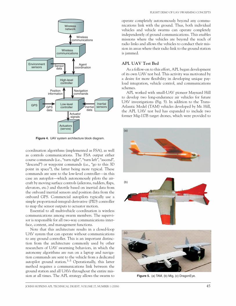
one critical result of these initial investigations was the development of a small uAV communications and control architecture.2 in this architecture, low- and high-level control are implemented by two separate control modules. A third module provides wireless com-munications (Fig. 4).
The high-level controller acts as the user inter-face, accepting the mission definition from the user and delivering sensor data and mission status to the user. The supervisor also implements the high-level
Figure 3. (left to right) Preparation for launch, launch, and landing of the L3-BAI Aerosystems Javelin.
Johns hopkins ApL TechnicAL DigesT, VoLume 27, number 1 (2006) 45
FLighT Demo oF uAV sWArming concepTs
coordination algorithms (implemented as FsA), as well as controls communications. The FsA output either course commands (i.e., “turn right”, “turn left”, “ascend”, “descend”) or waypoint commands (i.e., “go to this 3D point in space”), the latter being more typical. These commands are sent to the low-level controller—in this case an autopilot—which autonomously pilots the air-craft by moving surface controls (ailerons, rudders, flaps, elevators, etc.) and throttle based on inertial data from the onboard inertial sensors and position data from the onboard gps. commercial autopilots typically use a simple proportional-integral-derivative (piD) controller to map the sensor outputs to actuator motion.
essential to all multivehicle coordination is wireless communications among swarm members. The supervi-sor is responsible for all two-way communications inter-face, content, and management functions.
note that this architecture results in a closed-loop uAV system that can operate without communications to any ground controller. This is an important distinc-tion from the architecture commonly used by other researchers of uAV swarming behaviors, in which the autonomy algorithms are run on a laptop and naviga-tion commands are sent to the vehicle from a dedicated autopilot ground station.3–5 operationally, this latter method requires a communications link between the ground station and all uAVs throughout the entire mis-sion at all times. The ApL strategy allows the swarm to
operate completely autonomously beyond any commu-nications link with the ground. Thus, both individual vehicles and vehicle swarms can operate completely independently of ground communications. This enables missions where the vehicles are beyond the reach of radio links and allows the vehicles to conduct their mis-sion in areas where their radio link to the ground station is jammed.
APL UAV Test BedAs a follow-on to this effort, ApL began development
of its own uAV test bed. This activity was motivated by a desire for more flexibility in developing unique pay-load integration, vehicle control, and communications schemes.
ApL worked with small-uAV pioneer maynard hill to develop two long-endurance air vehicles for future uAV investigations (Fig. 5). in addition to the Trans- Atlantic model (TAm) vehicles developed by mr. hill, the ApL uAV test bed has expanded to include two former mig-117b target drones, which were provided to
Figure 4. UAV system architecture block diagram.
Figure 5. (a) TAM, (b) Mig, (c) DragonEye.
Low-levelcontroller
Actuatorsignals
Navigationcommands
Agentcoordination
Positioninformation
High-levelcontroller
Wirelesscommunications
Wirelesscommunications
Wirelessnetwork
GPSGPSdata
Inertialsensors
Actuators(servos)
Sensordata
Inertialdata
Environmentsensors
(a)
(b)
(c)
46 Johns hopkins ApL TechnicAL DigesT, VoLume 27, number 1 (2006)
r. J. bAmberger Jr. et al.
ApL by the Army research Laboratory (ArL) in Aber-deen, maryland.6 Two Dragoneye variants have also been used as part of the ApL flight demonstrations, but were given only temporarily by the naval research Lab-oratory (nrL) and are not part of the permanent ApL capability. because the Dragoneye has been used by the marines to such success recently, it is expected that the ApL test bed will include those vehicles as a permanent resource sometime in the near future.
For onboard implementation of the autonomous swarming behavior FsAs, a small, lightweight, coTs single-board computer is used. A coTs ieee 802.11b wireless local area network (WLAn) card is currently being used for swarm communications. For low-level vehicle control, two commercial autopilots have been used as part of the ApL test bed: the piccolo autopi-lot from cloud cap Technology and the mp2028 from micropilot.
CONSENSUS VARIABLES APPROACHAnother approach to autonomous, cooperative mul-
tiple vehicle behaviors was motivated by recent work on multi-agent coordination. This work is based on the idea of a consensus variable that is shared among the agents.7 The minimal amount of information required for coordinated behaviors is assumed to be encapsu-lated in a time-varying vector called the coordination, or consensus, variable. each agent carries its own local value of the consensus variable and updates that value based on the value held by other agents with whom the agent can communicate. Through proper definition of the consensus variable, and specification of rules for updating the value of this variable, it is possible for the value of the consensus variable to converge among the communicating agents.8
Assuming N agents with a shared consensus variable , each agent has a local value of the variable given as i. each agent updates its value based on the values of the agents with whom it can communicate. The continu-ous-time update rule is used, i.e.,
i ij i jN
ki
= − −∑ ( ) ,
where kij 0 is a weighting factor or gain that is non-zero when information flows from agent j to agent i and is zero otherwise. under certain conditions, convergence of the form i → * can be assured, with the final value of the consensus variable a function of both the initial conditions and the value of the gains.
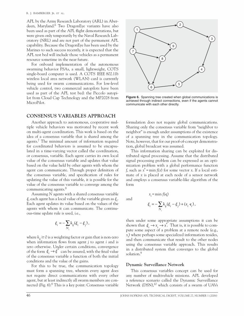
For this to be true, the communication topology must form a spanning tree, wherein every agent does not require direct communications with every other agent, but at least indirectly all swarm members are con-nected (Fig. 6).8 This is a key point: consensus variable
formulation does not require global communications. sharing only the consensus variable from “neighbor to neighbor” is enough under assumptions of the existence of a spanning tree in the communication topology. note, however, that for our proof-of-concept demonstra-tion, global broadcast was assumed.
This information sharing can be exploited for dis-tributed signal processing. Assume that the distributed signal processing problem can be expressed as an opti-mization problem with a global performance function f, such as x* = min f(x) for some vector x. if a local esti-mate of x is placed at each node of a sensor network and employs a consensus variable-like algorithm of the form
xi = min f(i)and i ij i j i i
N
k xi
= − − +∑ ( ) ( ) ,
then under some appropriate assumptions it can be shown that i ix x→ → *. That is, it is possible to com-pute some aspect of a problem at a remote node (e.g., xi) where perhaps some specialized information resides, and then communicate that result to the other nodes using the consensus variable approach. This results in a distributed system that converges to the global solution.9
Dynamic Surveillance NetworkThis consensus variables concept can be used for
any number of multivehicle missions. ApL developed a reference scenario called the Dynamic surveillance network (Dsn),10 which consists of a swarm of uAVs
Figure 6. Spanning tree created when global communications is achieved through indirect connections, even if the agents cannot communicate with each other directly.
3
4
56
7
1
2
9
8

Johns hopkins ApL TechnicAL DigesT, VoLume 27, number 1 (2006) 47
FLighT Demo oF uAV sWArming concepTs
exfiltrating data from a network of spatially distributed unattended ground sensors (ugss) in an urban environment. This scenario was chosen since for military operations in urban environments, there is an increasing demand for distributed sensor networks to provide tacti-cal or security forces timely, local, actionable operational intelligence. however, because of unreliable communications links in urban environments, and because these sensors may be in a denied area, direct communications back to a command post or to the warfighter cannot be assumed. swarms of small, inexpensive uAVs can create robust ad hoc mobile air networks that provide this critical communi-cations link. These swarms can be a fire-and-forget asset initiated by the soldier and can self-deploy and then operate continuously to reconfigure
3. Data exfiltration (collection and relay): After dis-covering the sensors, the uAVs solve an optimal coverage problem, determining the best course of action. using the consensus variables approach, the uAVs then negotiate among themselves to assign each one an individual flight pattern based on the optimal solution (Fig. 7c).
4. Adaptation: The Dsn system also adapts to changes in the network. if one of the sensor nodes becomes disabled, the uAVs detect this event and autono-mously reconfigure. Adaptation also occurs if a uAV leaves the area. For example, periodically the uAVs agree that one of them should return to the base station and relay the data that have been collected from the sensors. When this occurs the remaining uAV reconfigures its flight pattern by resolving the optimal coverage problem assuming a new number of available resources (Fig. 7d). The initial flight pattern is resumed upon the return of the relay uAV.
Flight Demonstration HardwareTwo different autonomous uAV platforms were used
at various times during the flight testing of the Dsn: the TAm and the mig-117b target drone. Autonomous piloting of the vehicles was accomplished through the piccolo autopilot. The consensus variables concepts were represented as a series of FsA, which generated Dsn mission behaviors such as discovery, negotiation, data exfiltration, and adaptation (Fig. 8). A coTs, risc-processor–based single-board computer was
Figure 7. Graphical depiction of a DSN scenario using two UAVs: (a) sensor deployment phase, (b) sensor discovery phase, (c) data exfiltration phase, and (d) adaptation phase.
for optimal communications, adapting robustly to com-ponent failures and battle damage.
A proof-of-concept flight demonstration was devel-oped in which multiple uAVs search, locate, and then coordinate with each other to most optimally exfiltrate the sensor data. Line-of-site (Los) communications were assumed from ugs to uAV, but not from ugs to ugs. Also, ugs-to-uAV communications were not assumed for the entire operational area. That is, a uAV could communicate with the ugs only within a limited area (an Los cone above the sensor, typical of “urban canyons”). Finally, only an approximate knowl-edge of the ugs locations was assumed, necessitating an initial discovery process. The global system goal was to optimize sensor data exfiltration to the base station. it is during this process that the consensus variables approach is used, with optimal flight paths being the global variable.
The following describes the scenario conops (con-cept of operations):
1. Setup: sensors are deployed (Fig. 7a). it is assumed that in general the sensors cannot communicate with each other.
2. Sensor discovery: before take-off, the user tasks the uAVs to find the sensors (Fig. 7b). each uAV solves an optimal raster scan problem based on the known number of sensors and their approximate locations. The uAVs then negotiate to assign each uAV an individual flight pattern. Finally, the uAVs fly the fixed flight pattern and record the gps location of the sensor nodes they have found.
(a) (b)
(c) (d)

48 Johns hopkins ApL TechnicAL DigesT, VoLume 27, number 1 (2006)
r. J. bAmberger Jr. et al.
used to implement these FsA, as well as enable user definition of the mission and control commu-nications. As noted earlier, while the hardware suite and software algorithms differed completely from those used during the simple team-ing approach flight tests, the basic uAV control and payload archi-tecture was the same, as was the approach of using FsAs to imple-ment behaviors.
The FsA that were used to implement behavior generated nav-igation commands (gps waypoint updates) that directed the vehi-cle altitude, velocity, and course. These navigation commands were sent over a serial interface to the autopilot in flight. The onboard computer also provided the drivers, data interface, control, and power for the WLAn card.
The ground sensors used for this test were laptops outfitted with WLAn cards. To simulate com-munications in an urban canyon, highly directional upward-point-ing antennas were used that pro-vided limited zones of connectivity
within the airspace and no connectivity among the sensors. because the objective was to demonstrate the consensus variables concept and not the sensors, no sensor data were transferred over the wireless link. For the flight tests, the discovery, exfiltration, and adap-tation stages used Tcp/ip “pings” rather than actual data exfiltration as confirmation of uAV-to-ugs connectivity.
Preliminary Demonstration ResultsFlight tests to date have demonstrated the ability to
fly autonomously while communicating with the laptop-based sensor emulation stations. A flight pattern was programmed for a single uAV for an area that contained three emulated ugss (Fig. 9). During the ugs flyovers, the uAV was able to ping the sensors, thus establishing sensor location. This preliminary test demonstrated the discovery phase of the scenario.
Testing was conducted by a joint ApL/ArL team at various locations at Aberdeen proving ground (Apg) in Aberdeen, maryland. These flight demonstrations are ongoing. Future tests are planned for demonstrating two air vehicles coordinating to configure flight patterns that result in optimal connectivity.Figure 8. FSA used to implement DSN mission.
Figure 9. Demonstration of discovery phase.
Loiterw/exfiltration
Manual
Loiterw/datatransfer
Loiterw/negotiate
Loiterw/exfiltration
E/FP,DCV
E/FP,DCV
ND/FP,DCV
ND/FP,DCV
CR/FP,DCV
T/FP,DCV
T/FP,DCV E/FP,
DCV
A/FP,DCV
MM
M M
Input/Output1, Output2, ...Inputs: A Automatic
CR Change requestE ErrorM ManualND Negotiation doneT TransferTP Transfer complete
Outputs: DCV Data Collection Variable FP Flight plan
N
1 211
300 ft
100 m
Sensor 1
Sensor 2
Sensor 3
Water
Water

Johns hopkins ApL TechnicAL DigesT, VoLume 27, number 1 (2006) 49
FLighT Demo oF uAV sWArming concepTs
STIGMERGIC POTENTIAL FIELDS APPROACH
stigmergy represents a fundamentally different approach to uAV swarming than the consensus vari-ables or simple teaming concepts. Those approaches coordinated vehicle actions through negotiation among swarm members or supervisory control designed to address mission objectives. With stigmergy, the coop-erative problem is solved by heterarchically organizing agents that coordinate indirectly by altering the envi-ronment and reacting to the environment as they pass through it. That is, the agents do not negotiate directly with each other to mutually decide on courses of action. stigmergy is accomplished through the use of locally executed control policies based on potential field for-mulas. These formulas, called stigmergic potential fields (spFs), are used to coordinate movement, transient acts, and task allocation among cooperating vehicles.11 While the previous approaches theoretically produce more optimal swarm behaviors, stigmergy results in behaviors that respond more quickly to changing events and can support swarms containing more members.
With spFs, a virtual potential field is associated with all the germane entities contained within a locally held model of the vehicle’s world. These models typically include peer vehicles and elements that are impacted by peer vehicles. These fields are used to influence vehicle action, most notably movement. The forces associated with the fields may be attractive (directing the vehicle toward a point), repulsive (directing the vehicle away from a point), or complex (a combination of attractive and repulsive fields) (Fig. 10). At any given time, the total force on a vehicle is the summation of all attrac-tive, repulsive, and complex forces due to all known influences.12 This approach to vehicle control borrows heavily from earlier work in vehicle path planning with potential fields. This work most closely relates to Arkin’s motor schema behavior, Zambonelli’s co-fields, spears’ physicomimetic behavior, and koren’s solutions to prob-lems of local minima and undesirable oscillations.13–16
Hierarchical Architecture and Communications Protocol
The hierarchical control architecture developed for the demonstration of these spF concepts consists of five essential layers (Fig. 11). each layer is an independently
executing control process. The upper layers exercise control over the lower layers by asynchronously altering the objectives of the lower levels. The top-most inter-modal behavior level controls transitions among the other behaviors. The intra-modal behavior level real-izes specific behavioral functions such as regulation of transient actions (e.g., vehicle course and speed). The reflexive behavioral layer provides collision avoidance and maneuvering while pursuing the course ordered by the intra-modal layer.
The sharing of knowledge among swarm members represents a cornerstone of the spF approach. “beliefs” (data structures) represent a swarm member’s knowledge of abstract objects in its environment, as well as its own position and state. These objects may be moving or sta-tionary. moving objects may include unknown vehicles, noncombatants, cooperating members of the swarm group, identifiable targets, and legitimate threats. in addition to those categories, stationary objects include topography obstacles.
beliefs are generated by the perception level, which senses the environment and vehicle status using physi-cal sensors. beliefs are provided by the perception layer to the vehicle’s inter-modal, intra-modal, and com-munications layers. The communications layer trans-fers these beliefs to other swarm members, as well as receives beliefs from other swarm members. The beliefs from the vehicle’s own perception layer, along with the beliefs from other swarm members, represent the core input to the algorithms that generate the stigmergic potential fields.
Figure 10. Fields that are (a) attractive, (b) repulsive, and (c) complex. An attractive field results in the vehicle being drawn toward its center, a repulsive field results in the vehicle being drawn away from its center, and a complex field is the combination of attractive and repulsive forces in one location.
Figure 11. Hierarchical control architecture used in the imple-mentation of the stigmergic approach.
(a) (b) (c)
Communications
Perception
Wirelessnetwork
Wirelesscommunications
Intra-modalbehavior
Reflexive
Velocity, course
Inter-modalbehavior
Events
Beliefs

50 Johns hopkins ApL TechnicAL DigesT, VoLume 27, number 1 (2006)
r. J. bAmberger Jr. et al.
clearly, the communications layer is a critical link in enabling stigmergic swarm behaviors. A commu-nications framework was developed for belief transfer that uses a modular, multilayered architecture (Fig. 12).17 This framework was designed to facilitate dis-tributed collaboration over any mobile ad hoc network (mAneT). At the core capabilities layer, the transmit subsystem provides periodic and on-demand message transmit capabilities that can be accessed by any vehicle software application.
The framework provides several functions, including a neighbor discovery capability that allows any node to identify peer nodes within its immediate wireless cover-age. it also allows any application to detect swarm size, as well as join and leave events. These events are com-monly encountered in wireless ad hoc networks where rapidly changing topology, varying rF link quality, and unpredictable obstacles can cause partitioning and merging of swarm clusters. The framework capabilities include collection, logging, and broadcast of various communication statistics.
This framework was designed to be highly adaptable for use in various applications and deployments where impromptu ad hoc communications are required. The system allows activation/deactivation of any of its sub-systems at software construction time and at run-time using configuration properties and the service inter-face. in most deployments scenarios, manual setup and administration are not required to establish the wireless network. Default configuration properties can
be established to allow operations in a wide range of environments. The framework uses these defaults to automatically initialize the communications soft-ware framework, without requiring the high-level application to understand the internal configuration details.
The framework protocols were designed to limit computational and communication resources, thereby limiting energy consumption. For example, forwarding specific application messages across one or more hops is allowed when these messages have been marked by the sending node for multi-hop forwarding. This forwarding service is designed to eliminate broadcast storms that occur with simple forwarding flooding techniques. The forwarding service protocol does not rebroadcast a mes-sage unless this rebroadcast allows the message to reach new receivers.
Demonstration of Communications ProtocolAn extensive series of simulations, hiL tests, and
flight tests were conducted to validate the communica-tions protocol. The flight tests were conducted at Apg by a team from ApL and ArL. The objective was to use an airborne WLAn node to hop messages between ground assets that could not communicate directly. The ground assets consisted of an unmanned ground vehicle (ugV), two ugVs emulated on a single laptop, and a laptop ground station that displayed messages and tracked vehicle movement. A helicopter uAV equipped with a WLAn card acted as the airborne node.
The three ground nodes were distributed through-out the test field such that none of the nodes had direct communications with each other. This was accom-plished by locating nodes far apart or behind obstacles such as buildings. The primary test metric was the suc-cessful multicast hopping of packets between ground nodes. This hopping was substantiated by using the ground station’s visual display of message transfers and vehicle motion. With the air vehicle at an altitude of approximately 100 m, it was flown to several locations around the test field. Within minutes the uAV reached a location that allowed messages to be forwarded from the robot ugV to the ground station, and from one of the emulated ugVs to the ground station. The laptop could emulate only one ugV at a time. When emula-tion of the first ugV was terminated and emulation of the second ugV was initiated, this was also reflected on the ground station. As a final test, the second emu-lated ugV attempted to ping the ground station but was unsuccessful despite messages being hopped from that ugV to the ground station. This verified that the emulated ugV was truly not in direct communications with the ground station and the airborne node was really hopping selective application messages as opposed to acting like an infrastructure relay node.
Figure 12. UAV swarm communications modular, multilayered architecture.
Broadcastforwarding
Receivesubsystem
Receiveservicesinterface
Operations,administration,
and management(OAM) interface
Transmitservicesinterface
OAMsubsystem
Cor
eca
pabi
litie
sE
nhan
ced
capa
bilit
ies
App
licat
ion
serv
ices
RF
com
mun
icat
ions
hard
war
e
Transmitsubsystem
TCP/IP stack
802.11Bnetwork
Receivewireless
impairmentsemulation

Johns hopkins ApL TechnicAL DigesT, VoLume 27, number 1 (2006) 51
FLighT Demo oF uAV sWArming concepTs
Demonstration of the SPF ApproachThe spF approach was used to implement seven
behaviors useful for military operations: search, track-ing, classification, friendly influence, circular formation, linear formation, and pheromone-based search. one of these behaviors, the cooperative search behavior, is described in some detail below.
The goal of cooperative search is to direct vehicle motion to accomplish complete sensor coverage of an area designated by a search order. simple cooperative search is determined at any arbitrary time t by having each vehicle apply the field
g rs
rp
t t
k
s
( )[ ( ) ]
( ),= − −
+
−1 1
1
l
where l vobj to all locations in Z2 space. The coeffi-cient s is the probability of detection for a sensor observ-ing the point in question, and ts is the most recent time the point was surveyed. The decay in knowledge of a previously observed area is controlled by the decay con-stant l, which is proportional to the expected speed of an adversary vobj. The constant k is used to adjust the cohesiveness of a search pattern. Further improvements to the cooperative search may be found by applying secondary fields to cooperating sensor and communica-tions platforms.
From July to september 2004 a series of experiments was conducted to demonstrate spFs in a real-world sce-nario. The behaviors demonstrated included search, tracking, classification, friendly influence, circular for-mation, and linear formation (Fig. 13). These experi-ments established the ability of a small heterogeneous swarm (two uAVs and four ugVs) to achieve a series of objectives provided asynchronously by three uncoor-dinated operators exercising effects-based control. The demonstrations increased in complexity throughout
Figure 13. UGVs classify contacts found by UAVs escorting a convoy.
the test period, culminating in an experiment to help protect fixed and mobile assets in an obstacle-laden urban area.
The uAV/ugV swarm was responsible for provid-ing reconnaissance, surveillance, and target acquisition capabilities in support of the mission objectives. mig-117b drones were used as the uAV vehicles, while the micro-pilot autopilot was used to control uAV flight. The FsAs that implemented the stigmergy behaviors and commu-nications protocols were run on a laptop and communi-cated to the uAV through the micropilot ground sta-tion. in other words, the FsAs were not implemented on an onboard computer. note, however, that this was only because the micropilot autopilot version that was used did not support commands from any source other than its ground station. in other words, the FsAs were not so computational intensive that they would not have fit on a small, single-board computer. Future migration to other autopilot systems will enable a completely inte-grated onboard command and control architecture.
These tests were also conducted at Apg by a joint ApL/ArL team. To ensure that the most realistic envi-ronmental stimuli possible were provided to the vehicle sensors within the limited test area, significant engineer-ing of the environment was necessary. runways were used to represent a road network. An urban area, including a power station and several buildings, was constructed of wood-reinforced foam board. A convoy was represented by an instrumented van containing an operator’s station. unknown contacts were represented by test personnel outfitted with range-limited position beacons.
The scenario was instantiated by an operator who broadcast a belief that a fixed asset (a notional power station at a known location) required protection. The autonomous ugVs, which had been prestaged ≈90 m away, responded by searching the urban area. once the area was completely searched, the ugVs secured the power station within a moving circular perimeter. concurrently, the local road network was patrolled by autonomous uAVs.
After several minutes, a second operator located within a mobile asset (a notional convoy) broadcast the belief that the convoy required continuous protection. When the uAVs detected the convoy they shifted behavior, changing from patrol to escort, providing air support for the convoy as it moved down the road. several contacts were staged at a road intersection. The contacts were identified by range-limited beacons designed to simulate an ir detection capability. As the convoy moved along the road network, the escorting uAVs detected these unknown contacts at an intersection. The existence of these unknown contacts was broadcast to all vehicles via the wireless network. The ugVs reacted to these new beliefs by forming a linear barrier between the unknown contacts and the power station. one ugV, which was equipped with a directional acoustic sensor, shifted to
Target1
Target2 HVA
Mini_agent
Mod0_agentMod1_agent
Display_created0

52 Johns hopkins ApL TechnicAL DigesT, VoLume 27, number 1 (2006)
r. J. bAmberger Jr. et al.
a classify behavior, closing with the unknown contacts including both noncombatants and a hostile target. The target was distinguished by an audible tone. The ugV with the classification sensor approached the contacts, classifying each as hostile or friendly strictly on the basis of the presence or absence of the tone. once the hos-tile contact was identified, all the ugVs responded by transitioning to track behavior. The hostile contact was pursued, surrounded, and neutralized by the ugVs.
The convoy-based operator then broadcast a belief that the intersection may contain explosives. simul-taneously, the original operator reenforced the belief that the power plant required protection. The ugVs responded by self-organizing to accomplish both tasks. significantly, the actions executed by the ugVs to this point were in direct response to the stimulus provided, with no human intervention.
The operational scenario was repeated successfully many times. While the specific movement of individual vehicles varied greatly, the collective behavior and effec-tiveness remained constant. Additional complexity was introduced by adding software agents such as virtual uAVs, an actual ugs, and mixes of virtual and actual ugVs.
hardware failures played a key role in understand-ing and demonstrating the robustness of the control algorithms. Two ugVs failed: one lost mobility and the other experienced a total power failure. The remain-ing vehicles continued to perform the mission with no explicit replanning and no operator intervention. Despite the hardware failures, the remaining vehicles were able to complete the mission objectives with only a 15% increase in scenario completion time.
experiment metrics included repeatability, consis-tency, behavioral stability, and robustness to failure of the distributed multivehicle control system. extensive recordings were made of vehicle positions, behavior transitions, position histories, and scenario events. The results were promising. The circular and linear forma-tion behaviors, used for fixed and mobile asset protec-tion, provided very stable and consistent performance. The consistency of the search and track behaviors, how-ever, was more varied. This was consistent with earlier simulated results that showed search efficiency to depend on the density of the vehicle community, size and dis-persion of the search, speed of the vehicle, and sweep rate of the sensor. since these dependencies are largely observable by the vehicles, it is believed that adaptive fields may be engineered to provide a consistently high degree of efficiency.
Application of the SPF Approach for Chemical/Biological Plume Detection
in september 2005 the spF approach was applied to a hazardous plume detection concept of operations.
rather than intended as a demonstration of spF, this was an actual application of spF to a defined problem.
The test was conducted at Dugway proving ground (Dpg) in Dugway, utah, by a joint ApL/nrL test team. A modified version of the Dragoneye air vehicle was used, along with a proprietary nrL autopilot. The FsAs that controlled the vehicle behavior were implemented on a laptop pc, which was connected to the autopilot ground station. To control velocity, altitude, and course, joystick commands spoofed by an ApL-developed soft-ware interface layer were sent to the ground station. As with the Apg demonstrations of the spF approach, this suboptimal hardware architecture was driven by limi-tations of the autopilot rather than the computational requirements of the software.
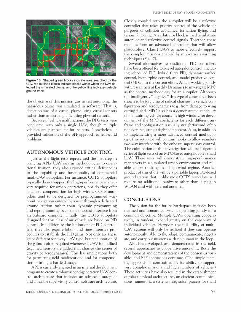
For this mission, a standoff detector or human observer provided to the uAV only notional informa-tion about the location of a chemical/biological release (Fig. 14). Without user input (only launching), the uAV was deployed to the plume and conducted an autono-mous search of the designated area (Fig. 15). simulated uAV chemical/biological sensors autonomously analyzed the suspected release zone. in the case of the chemical plume, the sensors identified the chemical agent and characterized the spatial extent of the plume (Fig. 16). in the case of the biological plume, the sensors collected the biological agent to be analyzed post-landing. because
Figure 15. Search area defined a priori by green blocks; simu-lated plume shown in red.
Figure 14. Chemical/biological plume detection scenario.
Standoff sensoror observer
Commandpost
UAVlaunch/landingarea
Winddirection
Range and bearing of cloudprovided by standoff system
or observer to define search area
Release
Johns hopkins ApL TechnicAL DigesT, VoLume 27, number 1 (2006) 53
FLighT Demo oF uAV sWArming concepTs
Figure 16. Shaded green blocks indicate area searched by the UAV, red outlined blocks indicate blocks within which the UAV de-tected the simulated plume, and the yellow line indicates vehicle ground track.
the objective of this mission was to test autonomy, the hazardous plume was simulated in software. That is, detection was of a virtual plume using virtual sensors rather than an actual plume using physical sensors.
because of vehicle malfunctions, the Dpg tests were conducted with only a single uAV, though multiple vehicles are planned for future tests. nonetheless, it provided validation of the spF approach to real-world problems.
AUTONOMOUS VEHICLE CONTROLJust as the flight tests represented the first step in
bringing ApL’s uAV swarm methodologies to opera-tional fruition, they also exposed critical deficiencies in the capability and functionality of commercial small-uAV autopilots. For instance, coTs autopilots typically do not support the high-performance maneu-vers required for urban operations, nor do they offer adequate compensation for high winds. coTs auto-pilots tend to be designed for preprogrammed way-point navigation entered by a user through a dedicated ground station rather than dynamic programming and reprogramming over some onboard interface from an onboard computer. Finally, the coTs autopilots designed for this class of air vehicle are based on piD control. in addition to the limitations of piD control-lers, they also require labor- and time-intensive pro-cedures to establish the piD gains. not only are these gains different for every uAV type, but recalibration of the gains is often required whenever a uAV is modified (e.g., new sensors are added that change the center of gravity or aerodynamics). This has implications both for permitting field modifications and for compensa-tion of in-flight battle damage.
ApL is currently engaged in an internal development program to create a robust second-generation uAV con-trol architecture that includes an advanced autopilot and a flexible supervisory control software architecture.
closely coupled with the autopilot will be a reflexive controller that takes priority control of the vehicle for purposes of collision avoidance, formation flying, and terrain following. An arbitrator block is used to arbitrate autopilot and reflexive control signals. Together, these modules form an advanced controller that will allow platoon-level class i uAVs to more effectively support the complex missions enabled by innovative swarming techniques (Fig. 17).
several alternatives to traditional piD controllers have been offered for low-level autopilot control, includ-ing scheduled piD, hybrid fuzzy piD, dynamic surface control, biomorphic control, and model predictive con-trol (mpc). in the current effort, ApL is working jointly with researchers at earthly Dynamics to investigate mpc as the control methodology for an autopilot. Although not intelligently “adaptive,” this type of control has been shown to be forgiving of radical changes in vehicle con-figuration and aerodynamics (e.g., from damage to wing during flight). mpc also has a demonstrated capability of maintaining vehicle course in high winds. user devel-opment of the mpc coefficients for each different air-frame and configuration is usually straightforward, often not even requiring a flight component. Also, in addition to implementing a more advanced control methodol-ogy, this autopilot will contain hooks to allow seamless two-way interface with the onboard supervisory control. The culmination of this investigation will be a rigorous series of flight tests of an mpc-based autopilot on a small uAV. These tests will demonstrate high-performance maneuvers in a simulated urban environment and reli-able course tracking in a high-wind regime. Another product of this effort will be a portable laptop pc-based ground station that, unlike most coTs autopilots, will require no additional hardware other than a plug-in WLAn card with external antenna.
CONCLUSIONSThe vision for the future battlespace includes both
manned and unmanned systems operating jointly for a common objective. multiple uAVs operating coopera-tively, in tandem, expand greatly on the capability of individual vehicles. however, the full utility of multi-uAV systems will only be realized if they can operate autonomously: able to fly, adapt, communicate, negoti-ate, and carry out missions with no human in the loop.
ApL has developed, and demonstrated in the field, several approaches to cooperative autonomy. both the development and demonstrations of the consensus vari-ables and spF approaches continue. (The simple team-ing approach is constrained by its ability to support very complex missions and high numbers of vehicles.) These activities have also resulted in the establishment of robust payload architectures, an efficient communica-tions framework, a systems integration process for small

54 Johns hopkins ApL TechnicAL DigesT, VoLume 27, number 1 (2006)
r. J. bAmberger Jr. et al.
Wireless network
Wirelesscommunications layer
Coordinationdecision
logic
Sensor data, swarmmembers positions/status, negotiation
Vehicle position/status, negotiation,
sensor data
Swarmmemberspositions/
status,negotiation
Vehicleposition/status,
negotiation,sensor data
Localdecision
logic
Reflexivecontroller
Payloadsensors
Reflexivesensors
Arbitrator
Actuators(servos)
Execution layer
Actuatorinterface
Inertialsensors/
GPS
Advanced autopilot
Hig
h-le
vel c
ontr
olle
r
Low
-leve
l con
trol
ler
Sensordata
Sensordata
Actuatorcontrolsignals
Actuatorcontrolsignals
Actuatorcontrolsignals
Sensordata
GPSsignals
Vehicle position
Waypoint navigation commands
Single vehicle architecture
Figure 17. Advanced UAV architecture.
vehicles, and an ApL uAV test bed. Future develop-ments will result in an integrated, advanced uAV con-trol architecture that will be realized in hardware.
With interest in both small systems and autonomy growing rapidly throughout the national defense com-munities, the future for multivehicle swarming concepts using small, autonomous uAVs looks bright. As a result of its commitment to developing these concepts, ApL is positioning itself to be a key innovator in these tech-nologies.
AcknoWLeDgmenTs: The uAV activities de-scribed in this article span several projects that include contributors from across ApL as well as outside ApL. The initial uAV teaming activities were led by hal gilreath, and key contributors included george barrett, Jim bruzek, Dale elkiss, Timothy gion, kenneth gross-man, and Frank Weiskopf. bAi Aerosystems also must be recognized for providing vehicles and flight services. establishment of the initial ApL uAV test bed relied heavily on the experience and knowledge of maynard hill, who was assisted by ApL student intern cyrus Ab-dollahi. implementation and demonstration of the stig-mergic fields approach using heterogeneous unmanned vehicle teams were made possible by the considerable efforts of bob chalmers, chris chiu, chad hawthorne,
Todd neighoff, and Jason stipes. osama Farrag created the communications framework that made realization of those concepts possible. Dennis Lucarelli contributed to solving the Dsn problem using consensus variables, and implementation and testing of the Dsn concept would not have been possible without the efforts of michael J. White. ArL personnel have played key roles through-out many of the flight demonstrations, particularly har-ris edge, robert hayes, and stephen Wilkerson. The Dugway test team was led by eric Van gieson, and included mr. chalmers, mr. chiu, peter Fuechsel, mr. hawthorne, and ronald mitnick. The advanced uAV controller is being developed with earthly Dynamics founder mark costello, a professor at georgia Tech uni-versity, and senior partner nathan slegers, a professor at the university of Alabama at huntsville. Additional internal collaborators include Andrew harris, Tony Le, Jay moore, neil palumbo, and matthew para.
reFerences 1Weiskopf, F., gion, T., elkiss, D., gilreath, h., bruzek, J., et al.,
“control of cooperative Autonomous unmanned Aerial Vehicles,” in Proc. AIAA 1st Technical Conf. and Workshop on Unmanned Aero-space Vehicles, Systems, Technologies, and Operations, AiAA 2002-3444 (2002).
2bamberger, r., bruzek, J., gilreath, h., gion, T., and grossman, k., “An Architecture for multi-Vehicle Autonomy with small uAVs,” in Proc. AHSI 59th Annual Forum, phoenix, AZ (2003).
Johns hopkins ApL TechnicAL DigesT, VoLume 27, number 1 (2006) 55
FLighT Demo oF uAV sWArming concepTs
THE AUTHORS
robert J. bamberger Jr.
David p. Watson
David h. scheidt
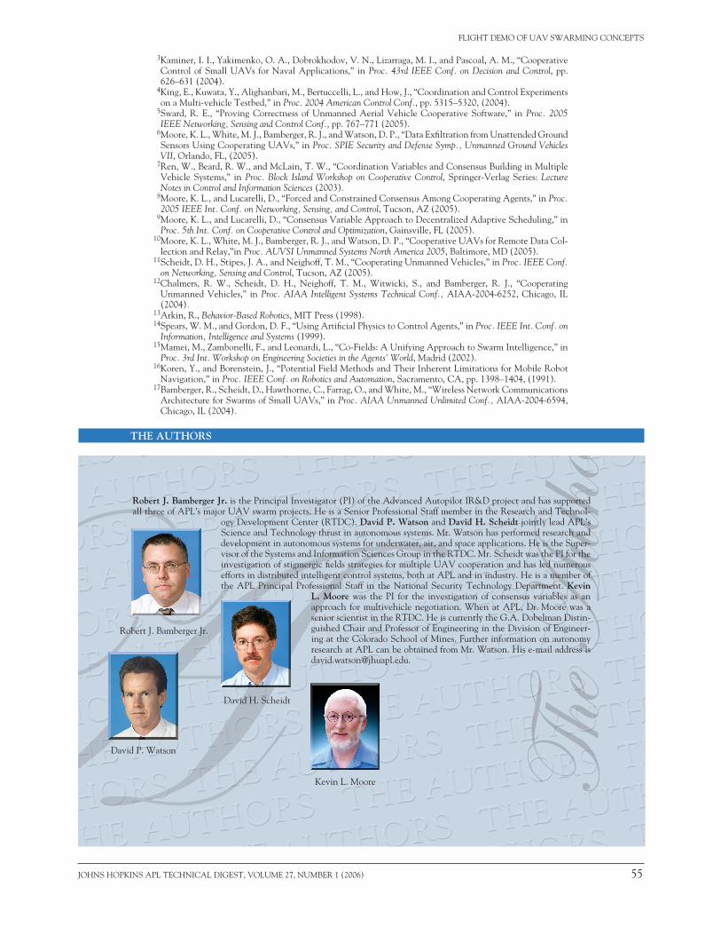
Robert J. Bamberger Jr. is the principal investigator (pi) of the Advanced Autopilot ir&D project and has supported all three of ApL’s major uAV swarm projects. he is a senior professional staff member in the research and Technol-
ogy Development center (rTDc). David P. Watson and David H. Scheidt jointly lead ApL’s science and Technology thrust in autonomous systems. mr. Watson has performed research and development in autonomous systems for underwater, air, and space applications. he is the super-visor of the systems and information sciences group in the rTDc. mr. scheidt was the pi for the investigation of stigmergic fields strategies for multiple uAV cooperation and has led numerous efforts in distributed intelligent control systems, both at ApL and in industry. he is a member of the ApL principal professional staff in the national security Technology Department. Kevin
L. Moore was the pi for the investigation of consensus variables as an approach for multivehicle negotiation. When at ApL, Dr. moore was a senior scientist in the rTDc. he is currently the g.A. Dobelman Distin-guished chair and professor of engineering in the Division of engineer-ing at the colorado school of mines. Further information on autonomy research at ApL can be obtained from mr. Watson. his e-mail address is [email protected].
3kaminer, i. i., Yakimenko, o. A., Dobrokhodov, V. n., Lizarraga, m. i., and pascoal, A. m., “cooperative control of small uAVs for naval Applications,” in Proc. 43rd IEEE Conf. on Decision and Control, pp. 626–631 (2004).
4king, e., kuwata, Y., Alighanbari, m., bertuccelli, L., and how, J., “coordination and control experiments on a multi-vehicle Testbed,” in Proc. 2004 American Control Conf., pp. 5315–5320, (2004).
5sward, r. e., “proving correctness of unmanned Aerial Vehicle cooperative software,” in Proc. 2005 IEEE Networking, Sensing and Control Conf., pp. 767–771 (2005).
6moore, k. L., White, m. J., bamberger, r. J., and Watson, D. p., “Data exfiltration from unattended ground sensors using cooperating uAVs,” in Proc. SPIE Security and Defense Symp., Unmanned Ground Vehicles VII, orlando, FL, (2005).
7ren, W., beard, r. W., and mcLain, T. W., “coordination Variables and consensus building in multiple Vehicle systems,” in Proc. Block Island Workshop on Cooperative Control, springer-Verlag series: Lecture Notes in Control and Information Sciences (2003).
8moore, k. L., and Lucarelli, D., “Forced and constrained consensus Among cooperating Agents,” in Proc. 2005 IEEE Int. Conf. on Networking, Sensing, and Control, Tucson, AZ (2005).
9moore, k. L., and Lucarelli, D., “consensus Variable Approach to Decentralized Adaptive scheduling,” in Proc. 5th Int. Conf. on Cooperative Control and Optimization, gainsville, FL (2005).
10moore, k. L., White, m. J., bamberger, r. J., and Watson, D. p., “cooperative uAVs for remote Data col-lection and relay,”in Proc. AUVSI Unmanned Systems North America 2005, baltimore, mD (2005).
11scheidt, D. h., stipes, J. A., and neighoff, T. m., “cooperating unmanned Vehicles,” in Proc. IEEE Conf. on Networking, Sensing and Control, Tucson, AZ (2005).
12chalmers, r. W., scheidt, D. h., neighoff, T. m., Witwicki, s., and bamberger, r. J., “cooperating unmanned Vehicles,” in Proc. AIAA Intelligent Systems Technical Conf., AiAA-2004-6252, chicago, iL (2004).
13Arkin, r., Behavior-Based Robotics, miT press (1998).14spears, W. m., and gordon, D. F., “using Artificial physics to control Agents,” in Proc. IEEE Int. Conf. on
Information, Intelligence and Systems (1999).15mamei, m., Zambonelli, F., and Leonardi, L., “co-Fields: A unifying Approach to swarm intelligence,” in
Proc. 3rd Int. Workshop on Engineering Societies in the Agents’ World, madrid (2002).16koren, Y., and borenstein, J., “potential Field methods and Their inherent Limitations for mobile robot
navigation,” in Proc. IEEE Conf. on Robotics and Automation, sacramento, cA, pp. 1398–1404, (1991). 17bamberger, r., scheidt, D., hawthorne, c., Farrag, o., and White, m., “Wireless network communications
Architecture for swarms of small uAVs,” in Proc. AIAA Unmanned Unlimited Conf., AiAA-2004-6594, chicago, iL (2004).
kevin L. moore