flight behavior of the rhinoceros beetle trypoxylus ...mk489/pdf/bb2012.pdf · flight behavior of...
TRANSCRIPT

Flight behavior of the rhinoceros beetle Trypoxylus dichotomus during electrical nerve
stimulation
This article has been downloaded from IOPscience. Please scroll down to see the full text article.
2012 Bioinspir. Biomim. 7 036021
(http://iopscience.iop.org/1748-3190/7/3/036021)
Download details:
IP Address: 141.5.35.229
The article was downloaded on 20/06/2012 at 10:20
Please note that terms and conditions apply.
View the table of contents for this issue, or go to the journal homepage for more
Home Search Collections Journals About Contact us My IOPscience
IOP PUBLISHING BIOINSPIRATION & BIOMIMETICS
Bioinspir. Biomim. 7 (2012) 036021 (11pp) doi:10.1088/1748-3182/7/3/036021
Flight behavior of the rhinoceros beetleTrypoxylus dichotomus during electricalnerve stimulationTien Van Truong1, Doyoung Byun2,7, Laura Corley Lavine3,Douglas J Emlen4, Hoon Cheol Park5 and Min Jun Kim6
1 Department of Aerospace Information Engineering, Konkuk University, Seoul 143-701,Korea2 Department of Mechanical Engineering, Sungkyunkwan University, Suwon 440-746,Korea3 Department of Entomology, Washington State University, Pullman, WA 99164, USA4 Division of Biological Sciences, University of Montana, Missoula, MT 59812, USA5 Department of Advanced Technology Fusion, Konkuk University, Seoul 143-701, Korea6 Department of Mechanical Engineering and Mechanics, Drexel University, Philadelphia, PA 19104,USA
E-mail: [email protected]
Received 20 February 2012Accepted for publication 15 May 2012Published 19 June 2012Online at stacks.iop.org/BB/7/036021
AbstractNeuronal stimulation is an intricate part of understanding insect flight behavior and controlinsect itself. In this study, we investigated the effects of electrical pulses applied to the brainand basalar muscle of the rhinoceros beetle (Trypoxylus dichotomus). To understand specificneuronal stimulation mechanisms, responses and flight behavior of the beetle, four electrodeswere implanted into the two optic lobes, the brain’s central complex and the ventral nerve cordin the posterior pronotum. We demonstrated flight initiation, turning and cessation bystimulating the brain. The change undergone by the wing flapping in response to the electricalsignal was analyzed from a sequence of images captured by a high-speed camera. Here, weprovide evidence to distinguish the important differences between neuronal and muscularflight stimulations in beetles. We found that in the neural potential stimulation, both the hindwing and the elytron were suppressed. Interestingly, the beetle stopped flying whenever astimulus potential was applied between the pronotum and one side of the optic lobe, orbetween the ventral nerve cord in the posterior pronotum and the central complex. In-depthexperimentation demonstrated the effective of neural stimulation over muscle stimulation forflight control. During electrical stimulation of the optic lobes, the beetle performed unstableflight, resulting in alternating left and right turns. By applying the electrical signal into boththe optic lobes and the central complex of the brain, we could precisely control the direction ofthe beetle flight. This work provides an insight into insect flight behavior for futuredevelopment of insect-micro air vehicle.
S Online supplementary data available from stacks.iop.org/BB/7/036021/mmedia
(Some figures may appear in colour only in the online journal)
7 Author to whom any correspondence should be addressed.
1748-3182/12/036021+11$33.00 1 © 2012 IOP Publishing Ltd Printed in the UK & the USA

Bioinspir. Biomim. 7 (2012) 036021 T Van Truong et al
1. Introduction
Electrical control of the locomotory patterns of animals isan active area of research. In short, this entails inducingartificial stimulation of an organism’s nervous system inorder to replicate and study naturally occurring processesof the organism. Several methods, such as direct electricalstimulation of muscles, electrical stimulation of neurons,projection of pheromones and stimulation of insect sensorycells, are used to control an insect’s ground and flightmovements [1]. For example, neural stimulation of thebrain has been demonstrated to control the locomotion of acockroach and a rat [2–4].
Insects are particularly well adapted for flight. Theexcellent flight performance of insects is primarily attributableto their large power-to-weight ratio [5]. Insects are capable oflong-distance flight, hovering and swift maneuvering [6, 7].Many studies have been conducted in order to understandthe aerodynamic characteristics of insect flight [8–11] withthe goal of developing micro air vehicles (MAVs) that willmimic an insect’s flight ability [12–18]. An insect maybe considered as an autonomous flying machine exhibitingbetter aerodynamic performance than any existing flyingmachine [19]. Controlling insect flight requires not onlytriggering flight initiation but also flight cessation behaviors,as well as controlling flight orientation [20]. Recent reportsdiscuss methods of controlling insect flight including muscleheating [21], chemical injection [22] and electrical stimulation[22–27]. In these studies, electrical stimulation exhibited lowpower consumption, easy integration with electronic systemsand immediate response times [27]. However, quantitativestudies examining the flight dynamics of an insect underthe control of neural stimulation have not been previouslyconducted in any insect species.
Direct electrical stimulation of muscles and neuronshad been used for controlling insects traveling in flightand on ground. Sato et al demonstrated the remote controlof a Mecynorrhinatorquata beetle via neural and muscularstimulations [24, 25]. Flight initiation and cessation werecontrolled using two electrodes implanted into the beetle’sbrain to stimulate the optic lobes. Control of turning wasachieved through direct muscular stimulation of either rightor left basalar flight muscles. However, specific neuronalmechanisms of beetles have not been thoroughly studied for thepurpose of applying control functions to beetle flight initiation,cessation and turns. Furthermore, such mechanisms are notperfectly understood in any insect; although specific nervoussystem components have been studied in order to investigateadaptive behaviours of insects through visual, chemical andmechanical stimuli [28–30]. A useful finding from those worksis that the insect brain can initiate and modulate flight viafiber neurons in response to stimulation of the visual, auditory,or wind receptors [31]. In addition, brain reconstruction ofmany insect species, such as Drosophila melanogaster [32],a honeybee [33], a desert locust [34] and the sphinx mothManducasexta [35] has previously been described.
The rhinoceros beetle T. dichotomus is a large beetlethat is easily raised across Asia. Due to its large size, the
rhinoceros beetle is especially well suited as a candidate forthe development of a MAV. In this study, we investigatedthe behavior of the beetle under electrical neural stimulationand the implementation of initiation, cessation and turningof the flight thereafter. In order to properly and preciselyplace the stimulation electrodes within the beetle’s brain,we reconstructed a model of the brain of T. dichotomususing scanning electron microscopy and micro-computedtomography (CT) imaging. We then quantitatively measure theeffects of electrical pulses applied to the brain and the basalarmuscle of T. dichotomus. Four electrodes were implanted intothe two optic lobes, the central complex (CC) in the brain andthe ventral nerve cord in the posterior pronotum in order toimplement flight control which includes flight initiation, flightdirection and cessation. As stated earlier, neural stimulationwas employed to trigger flight initiation and cessation aswell as to alter the insect’s flight orientation. Moreover, weobserved beetle behavior in response to different combinationsof electrical signals transmitted to the four electrodes. Wevisualized the beetle’s flapping and investigated its flightcharacteristics. Based on the qualitative and quantitativeanalysis, we presented a method to control an insect for MAV.
2. Materials and methods
T. dichotomus is one of the largest insect species, weighing6–10 g, which made it a suitable candidate for payloadcarriage.
2.1. Beetle anatomy
2.1.1. Scanning electron microscope (SEM) image of T.dichotomus brain. The whole brain was removed fromthe head exoskeleton prior to treatment. After beetle headdissection, the sample was placed in 4% paraformaldehyde.The tissue was rinsed of paraformaldehyde in cacodylate buffer(pH 7.2) followed by 10 min ethanol dehydration steps using35%, 50%, 70%, 85%, 95%, and two times at 100% EtOH.The tissue was placed in Balzer’s CPD030 critical point dryerand dried using the standard protocol (replacing the EtOH withliquid CO2 and heating it to the critical point, followed by aslow release of the pressure). The dried sample was sputtercoated with approximately 30 nm of thick gold/palladiumcoating using a sputter (Pelco Model 3) and then imaged ina SEM (Hitachi S-4700) at an accelerating voltage of 5 kVwith a working distance of 12 mm and emission current of16500 A.
2.1.2. Micro-CT. T. dichotomus was anesthetized withCO2 and the head was cut off from the body. The head wassubsequently put in a freezer at −5 ◦C for 30 min to becompletely immobilized. The head capsule was mounted onthe stage of the micro-CT machine. After the reconstructionfrom the raw images, the brain and optic lobes could beidentified from the corresponding slice of the images. Theoptic lobes connect the brain to the compound eyes on boththe left and right sides. Similarly, the female head was mountedon the micro-CT stage and scanned for 2 h and 37 min.
2

Bioinspir. Biomim. 7 (2012) 036021 T Van Truong et al
(a)
(b)
Figure 1. (a) A top view of an implanted electrode into CC. (b) The schematic of the experimental layout for the electrical stimulation.
The parameters for scanning were calibrated using an imageof smaller pixel size in order to determine the minimumimage resolution needed to provide sufficient details whileavoiding long scan time. In figure 2(b), the brain and opticlobes can be clearly observed even after the pixel size wasreduced to 5.52 μm. All of the images were taken usinga high-resolution micro-CT (Skyscan1172) and its built-inreconstruction software.
2.2. Flight stimulation experiments
The beetles were kept on organic peat misted with 50%humidity and temperature of 25 ◦C. The beetles were starvedfor 24 h before the stimulation experiments. To anesthetizethe beetles, each beetle was placed into a chamber withcarbon dioxide gas for at least 30 s. To determine the specificand precise location for stimulation, the cuticle and tissuesobstructing visibility of the brain from entry point are removedprior to electrode implantation. A micromanipulator and a verysmall probe (∼50 × 15 μm2) are used to cut a shallow hole inthe brain sheath (figure 1(a)). A small (80 μm) double-braidedwire is then attached to the manipulator and carefully insertedinto the hole.
After obtaining information about the dimensions andmorphology of the brain of T. dichotomus using the SEM,we were able to determine the optimal size of the electrode.Moreover, the three-dimensional morphology of the brain inthe head capsule reconstructed using the micro-CT images
allowed us to determine the position at which the electrodesshould be implanted for neural stimulation. Using opticalmicroscope imaging, we can verify the position of theelectrodes post-implantation (figure 1(a)).
A needle was used to pierce four small holes throughthe beetle’s cuticle: at the interior edge of the left and rightcompound eyes for optic lobe, at the center complex of thebrain and at ventral nerve cord in the center of the posterior ofpronotum. In order to test the muscle response with a potential,a hole was made midway between the sternum and notum ofthe mesothorax in order to access the direct flight muscles.For response testing, four steel wires (working as electrodes)were implanted into the small holes. A schematic diagramof the experimental apparatus is shown in figure 1(b). Twohalogen lamps with a power of 1 kW were placed at appropriatepositions to illuminate the region. The high-speed cameralens was connected to a camera and computer, while PhotronFASTCAM Viewer software R©was used to capture images andcontrol the high-speed camera system. The beetle was hungby a wooden applicator stick fixed on its head using superglue. The position of the beetle was oriented perpendicularlyto the camera lens. The beetle’s wing motion was capturedwith a high-speed camera at 2000 frames per second (fps) in1 μs shutter time and 1024 × 1024 pixels screen resolutionfor the front view. The wires were connected to two functiongenerators (Agilent, 33220 A). The oscilloscope was used toexamine the characteristics of the applied potential. The high-speed camera was synchronized with the oscilloscope in order
3
Bioinspir. Biomim. 7 (2012) 036021 T Van Truong et al
(a)
(c) (d)
(b)
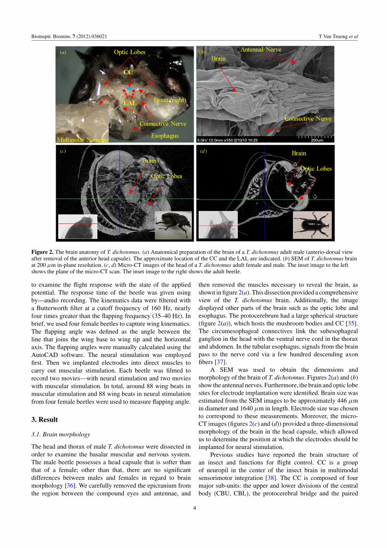
Figure 2. The brain anatomy of T. dichotomus. (a) Anatomical preparation of the brain of a T. dichotomus adult male (anterio-dorsal viewafter removal of the anterior head capsule). The approximate location of the CC and the LAL are indicated. (b) SEM of T. dichotomus brainat 200 μm in-plane resolution. (c, d) Micro-CT images of the head of a T. dichotomus adult female and male. The inset image to the leftshows the plane of the micro-CT scan. The inset image to the right shows the adult beetle.
to examine the flight response with the state of the appliedpotential. The response time of the beetle was given usingby—audio recording. The kinematics data were filtered witha Butterworth filter at a cutoff frequency of 160 Hz, nearlyfour times greater than the flapping frequency (35–40 Hz). Inbrief, we used four female beetles to capture wing kinematics.The flapping angle was defined as the angle between theline that joins the wing base to wing tip and the horizontalaxis. The flapping angles were manually calculated using theAutoCAD software. The neural stimulation was employedfirst. Then we implanted electrodes into direct muscles tocarry out muscular stimulation. Each beetle was filmed torecord two movies—with neural stimulation and two movieswith muscular stimulation. In total, around 88 wing beats inmuscular stimulation and 88 wing beats in neural stimulationfrom four female beetles were used to measure flapping angle.
3. Result
3.1. Brain morphology
The head and thorax of male T. dichotomus were dissected inorder to examine the basalar muscular and nervous system.The male beetle possesses a head capsule that is softer thanthat of a female; other than that, there are no significantdifferences between males and females in regard to brainmorphology [36]. We carefully removed the epicranium fromthe region between the compound eyes and antennae, and
then removed the muscles necessary to reveal the brain, asshown in figure 2(a). This dissection provided a comprehensiveview of the T. dichotomus brain. Additionally, the imagedisplayed other parts of the brain such as the optic lobe andesophagus. The protocerebrum had a large spherical structure(figure 2(a)), which hosts the mushroom bodies and CC [35].The circumesophageal connectives link the subesophagealganglion in the head with the ventral nerve cord in the thoraxand abdomen. In the tubular esophagus, signals from the brainpass to the nerve cord via a few hundred descending axonfibers [37].
A SEM was used to obtain the dimensions andmorphology of the brain of T. dichotomus. Figures 2(a) and (b)show the antennal nerves. Furthermore, the brain and optic lobesites for electrode implantation were identified. Brain size wasestimated from the SEM images to be approximately 446 μmin diameter and 1640 μm in length. Electrode size was chosento correspond to these measurements. Moreover, the micro-CT images (figures 2(c) and (d)) provided a three-dimensionalmorphology of the brain in the head capsule, which allowedus to determine the position at which the electrodes should beimplanted for neural stimulation.
Previous studies have reported the brain structure ofan insect and functions for flight control. CC is a groupof neuropil in the center of the insect brain in multimodalsensorimotor integration [38]. The CC is composed of fourmajor sub-units: the upper and lower divisions of the centralbody (CBU, CBL), the protocerebral bridge and the paired
4

Bioinspir. Biomim. 7 (2012) 036021 T Van Truong et al
Table 1. Control of flight initiation by electrical stimulation of the two optic lobes of T. dichotomus.
Samples 1 2 3 4 5 6 7 8 9 10
Mb (g) 3.96 4.67 4.65 3.98 4.35 5.25 4.58 5.12 4.86 4.87Hind wing length (mm) 43.86 44.35 42.23 43.67 42.26 47.87 45.3 48.11 45.56 44.81Elytron length (mm) 24.15 24.92 25.21 24.12 24.73 26.19 25.1 25.98 25.56 25.27Amplitude (V) 1.3 3.2 2.5 3.5 2.9 3.9 2.3 3.7 2.2 3.6Stimulation time for continuous flight (s) 22.53 24.32 24.6 20.79 21.16 23.47 25.02 23.53 24.36 20.85Response time for initiation (s) 9.08 8.72 4.29 2.38 1.85 2.67 6.14 1.43 1.01 10.93
nodule [39]. Structural CC mutants in Drosophila showeddefects in directional control flight [40]. The lateral accessorylobe (LAL) is a neuropil area in the protocerebrum of the brain.A role of the CC in flight control might be accomplishedvia pathways through the LAL [41]. The CC respondedto visual, chemical, mechanical stimuli [42] and electricalstimulation [43]. The optic lobe consists of three neuropils: thelamina, medulla, and lobula complex [44]. The electrical signalof the optic lobe toward the central brain apparently playsimportant roles in locomotor rhythm [45]. The movement ofthe flight muscles could be produced by the stimulation of thecentral nervous system anywhere from brain to the abdominalcord [46]. Therefore, for the beetle in this study, the opticlobes, CC and ventral nerve cord may play a significant role toflight control. We selected and implanted four electrodes intothose positions in the beetle’s head.
3.2. Initiation and cessation of flight
Electrical activity was observed between the optic lobes, whichare connected to the brain through the efferent neuron [47].Action potentials were found to be localized in the origin,arising from the deeper part of the second synaptic region,and in some cases also from the third synaptic region of theoptic lobe [48]. Electrical activity between the two optic lobesusually develops spontaneously, showing regular sinusoidalwaves where it has been described [48]. In this study, weobserved natural sinusoidal waves between the optic lobeswhich had a 1 Hz frequency for T. dichotomus (see movie S1,available from http://stacks.iop.org/BB/7/036021/mmedia).The bipolar electrodes in the optic lobes generated the shocks,which simultaneously elicited one-to-one junction potential inall dorsal longitudinal muscles [49].
At first, we attempted to control flight initiation andcessation using electrical stimulation between the fourelectrodes implanted in the two optic lobes, the brain’s CCand the ventral nerve cord in the posterior pronotum. Weimplanted the electrode into the posterior pronotum wherethe ventral nerve cord runs across for cessation of the flight.Nerve cells are linked together and transmit informationas electrical current to other nerve cells or muscle cells.We speculated that the transmission of the signal throughthe nerve system to make fly would be disturbed due tothe externally applied electrical potential. By applying theelectrical stimuli between the optic lobe and the pronotum,we could demonstrate the cessation of the flight. Variousfrequencies, amplitudes and wave forms were employedbetween the two electrodes in order to identify the optimalsignal. Ten active female beetles were chosen for the
experiment primarily because female beetles exhibit moreactive flight abilities than male beetles [50].
When attempting to control flight initiation, we foundthat only the rectangular wave form was able to elicit theinitiation of beetle flight: eight of the ten beetles initiatedflight with alternating positive and negative potential pulses,while the other two beetles started their flights with positivepulses. The optimal frequency was 1 Hz, which is identicalto the frequency of the sinusoidal wave’s electrical activitybetween the optic lobes, indicating that the applied rectangularpulse should be synchronized with the natural electrical signalbetween the optic lobes. Generally, coleopteran insects possessasynchronous flight muscles which oscillate under indirectcontrol [51]. Duch and Pfluger found that neuron innervatedflight muscle triggers flight with frequencies between 0.1and 1 Hz for a locust, which has a flapping frequency ofaround 25 Hz [52]. Similarly, because the beetle possessesasynchronous flight muscles, the flapping frequency of thebeetle is 35 Hz, which is much greater than the optimalinitiation frequency of 1 Hz. It should be noted that in thesespecies, motor neurons to the flight muscles release at muchlower frequencies than the wing oscillation frequencies [53].The asynchronous operation has been favored by evolution inflight systems of different insect groups because it generatesgreater output at the high contraction frequency of flight [53].
Table 1 shows the response time for flight initiationand duration of the stimulation for continuous flight evenafter turning off the stimulation. The optimal duty cyclewas 50% for eight beetles and 20% for two beetles. Theduty cycle was defined by the ratio of the positive pulsetime to one cycle duration time. The threshold amplitude ofthe potential varied from 1.3 to 3.9 V. When the electricalpotential was lower or higher than the threshold voltage,the beetles did not fly and the body just contracted dueto the electrical shock. When the potential frequency wasless than 1 Hz, beetles exhibited interrupted flight. Atpositive pulses, beetles repeated the initiation of flight;whereas, at negative pulses, beetles ceased flight (movie S2,available from http://stacks.iop.org/BB/7/036021/mmedia).Beetles were able to continue stable flight at 1 Hz even after theelectrical potential was turned off (movie S2, available fromhttp://stacks.iop.org/BB/7/036021/mmedia). However, whenthe duration of the applied potential was less than 20 s,all beetles ceased flight when the potential was turned off(table 1). When the duration time was longer than around 25 s,beetles continued flight even after the potential was turned off.
We also investigated three different methods forflight cessation. First, we applied an electrical pulse toboth optic lobes with a specific frequency or amplitude
5

Bioinspir. Biomim. 7 (2012) 036021 T Van Truong et al
Figure 3. Sequential images of the opening and closing motions of the elytra and unfolding and folding motion of the hind wing.(a-i) Natural opening and unfolding motion. (a-ii) Electrically stimulated opening and unfolding motion. (b-i) Natural closing and foldingmotion. (b-ii) Electrically stimulated closing and folding motion.
to end beetle flight. When the frequency increased to11 Hz, the beetle ceased flight (movie S3, available fromhttp://stacks.iop.org/BB/7/036021/mmedia). Second, if theamplitude of the applied pulse was increased to more than4 V, the cessation of flight was also achieved. In additionto these two ways, flight was stopped by application ofthe electrical stimulation pulse between either side of theoptic lobe and the ventral nerve cord, or between theCC and the ventral nerve cord (movie S3, available fromhttp://stacks.iop.org/BB/7/036021/mmedia).
To gain a clear understanding of artificially induced flightbehavior as it relates to natural flight, we visualized the detailed
motions of flight initiation and cessation and compared thosefindings to the motions of natural flight without electricalstimulus. Four electrodes were implanted into the two opticlobes, the CC and the ventral nerve cord in the posteriorpronotum. The alternating electrical pulses with amplitude of3.2 V, frequency of 1 Hz and duty cycle of 20% were appliedto four electrodes implanted into the left and right optic lobes,the CC and the ventral nerve cord. Figure 3 shows a seriesof photographs recorded at 2000 fps from the posterior ofthe insect. All of the tested beetles initiated flight during thepositive pulses.
6
Bioinspir. Biomim. 7 (2012) 036021 T Van Truong et al
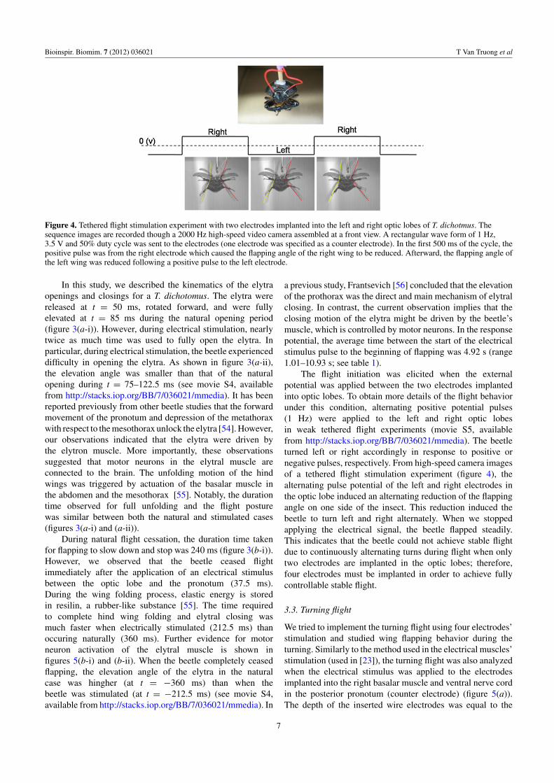
Figure 4. Tethered flight stimulation experiment with two electrodes implanted into the left and right optic lobes of T. dichotmus. Thesequence images are recorded though a 2000 Hz high-speed video camera assembled at a front view. A rectangular wave form of 1 Hz,3.5 V and 50% duty cycle was sent to the electrodes (one electrode was specified as a counter electrode). In the first 500 ms of the cycle, thepositive pulse was from the right electrode which caused the flapping angle of the right wing to be reduced. Afterward, the flapping angle ofthe left wing was reduced following a positive pulse to the left electrode.
In this study, we described the kinematics of the elytraopenings and closings for a T. dichotomus. The elytra werereleased at t = 50 ms, rotated forward, and were fullyelevated at t = 85 ms during the natural opening period(figure 3(a-i)). However, during electrical stimulation, nearlytwice as much time was used to fully open the elytra. Inparticular, during electrical stimulation, the beetle experienceddifficulty in opening the elytra. As shown in figure 3(a-ii),the elevation angle was smaller than that of the naturalopening during t = 75–122.5 ms (see movie S4, availablefrom http://stacks.iop.org/BB/7/036021/mmedia). It has beenreported previously from other beetle studies that the forwardmovement of the pronotum and depression of the metathoraxwith respect to the mesothorax unlock the elytra [54]. However,our observations indicated that the elytra were driven bythe elytron muscle. More importantly, these observationssuggested that motor neurons in the elytral muscle areconnected to the brain. The unfolding motion of the hindwings was triggered by actuation of the basalar muscle inthe abdomen and the mesothorax [55]. Notably, the durationtime observed for full unfolding and the flight posturewas similar between both the natural and stimulated cases(figures 3(a-i) and (a-ii)).
During natural flight cessation, the duration time takenfor flapping to slow down and stop was 240 ms (figure 3(b-i)).However, we observed that the beetle ceased flightimmediately after the application of an electrical stimulusbetween the optic lobe and the pronotum (37.5 ms).During the wing folding process, elastic energy is storedin resilin, a rubber-like substance [55]. The time requiredto complete hind wing folding and elytral closing wasmuch faster when electrically stimulated (212.5 ms) thanoccuring naturally (360 ms). Further evidence for motorneuron activation of the elytral muscle is shown infigures 5(b-i) and (b-ii). When the beetle completely ceasedflapping, the elevation angle of the elytra in the naturalcase was hingher (at t = −360 ms) than when thebeetle was stimulated (at t = −212.5 ms) (see movie S4,available from http://stacks.iop.org/BB/7/036021/mmedia). In
a previous study, Frantsevich [56] concluded that the elevationof the prothorax was the direct and main mechanism of elytralclosing. In contrast, the current observation implies that theclosing motion of the elytra might be driven by the beetle’smuscle, which is controlled by motor neurons. In the responsepotential, the average time between the start of the electricalstimulus pulse to the beginning of flapping was 4.92 s (range1.01–10.93 s; see table 1).
The flight initiation was elicited when the externalpotential was applied between the two electrodes implantedinto optic lobes. To obtain more details of the flight behaviorunder this condition, alternating positive potential pulses(1 Hz) were applied to the left and right optic lobesin weak tethered flight experiments (movie S5, availablefrom http://stacks.iop.org/BB/7/036021/mmedia). The beetleturned left or right accordingly in response to positive ornegative pulses, respectively. From high-speed camera imagesof a tethered flight stimulation experiment (figure 4), thealternating pulse potential of the left and right electrodes inthe optic lobe induced an alternating reduction of the flappingangle on one side of the insect. This reduction induced thebeetle to turn left and right alternately. When we stoppedapplying the electrical signal, the beetle flapped steadily.This indicates that the beetle could not achieve stable flightdue to continuously alternating turns during flight when onlytwo electrodes are implanted in the optic lobes; therefore,four electrodes must be implanted in order to achieve fullycontrollable stable flight.
3.3. Turning flight
We tried to implement the turning flight using four electrodes’stimulation and studied wing flapping behavior during theturning. Similarly to the method used in the electrical muscles’stimulation (used in [23]), the turning flight was also analyzedwhen the electrical stimulus was applied to the electrodesimplanted into the right basalar muscle and ventral nerve cordin the posterior pronotum (counter electrode) (figure 5(a)).The depth of the inserted wire electrodes was equal to the
7
Bioinspir. Biomim. 7 (2012) 036021 T Van Truong et al
(a) (b)
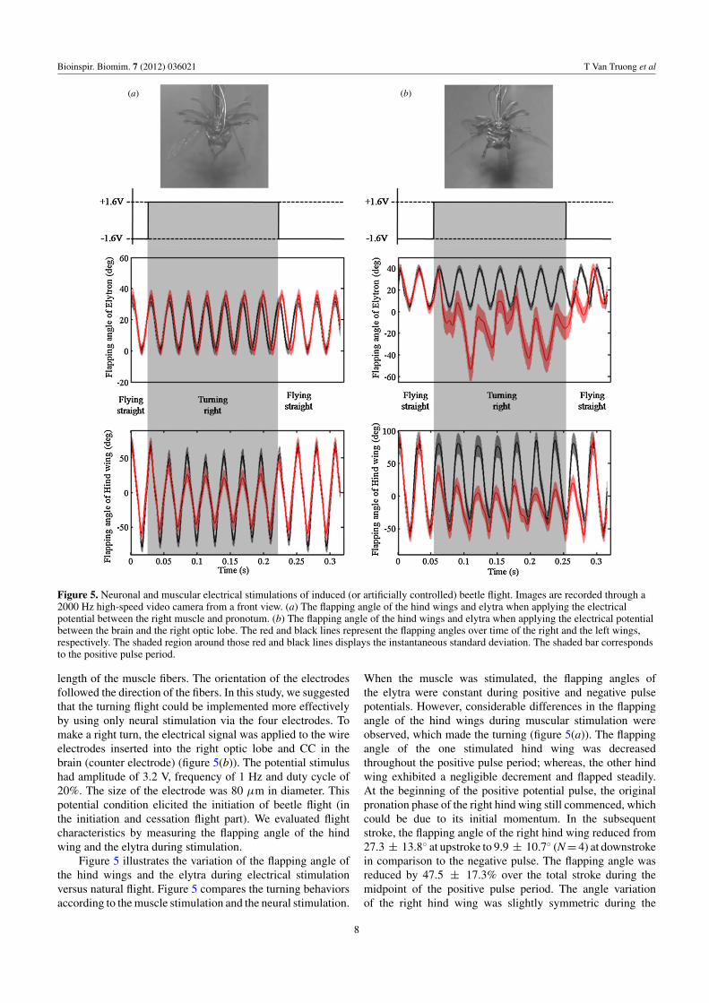
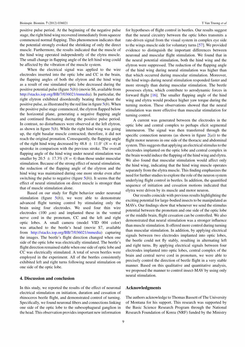
Figure 5. Neuronal and muscular electrical stimulations of induced (or artificially controlled) beetle flight. Images are recorded through a2000 Hz high-speed video camera from a front view. (a) The flapping angle of the hind wings and elytra when applying the electricalpotential between the right muscle and pronotum. (b) The flapping angle of the hind wings and elytra when applying the electrical potentialbetween the brain and the right optic lobe. The red and black lines represent the flapping angles over time of the right and the left wings,respectively. The shaded region around those red and black lines displays the instantaneous standard deviation. The shaded bar correspondsto the positive pulse period.
length of the muscle fibers. The orientation of the electrodesfollowed the direction of the fibers. In this study, we suggestedthat the turning flight could be implemented more effectivelyby using only neural stimulation via the four electrodes. Tomake a right turn, the electrical signal was applied to the wireelectrodes inserted into the right optic lobe and CC in thebrain (counter electrode) (figure 5(b)). The potential stimulushad amplitude of 3.2 V, frequency of 1 Hz and duty cycle of20%. The size of the electrode was 80 μm in diameter. Thispotential condition elicited the initiation of beetle flight (inthe initiation and cessation flight part). We evaluated flightcharacteristics by measuring the flapping angle of the hindwing and the elytra during stimulation.
Figure 5 illustrates the variation of the flapping angle ofthe hind wings and the elytra during electrical stimulationversus natural flight. Figure 5 compares the turning behaviorsaccording to the muscle stimulation and the neural stimulation.
When the muscle was stimulated, the flapping angles ofthe elytra were constant during positive and negative pulsepotentials. However, considerable differences in the flappingangle of the hind wings during muscular stimulation wereobserved, which made the turning (figure 5(a)). The flappingangle of the one stimulated hind wing was decreasedthroughout the positive pulse period; whereas, the other hindwing exhibited a negligible decrement and flapped steadily.At the beginning of the positive potential pulse, the originalpronation phase of the right hind wing still commenced, whichcould be due to its initial momentum. In the subsequentstroke, the flapping angle of the right hind wing reduced from27.3 ± 13.8◦ at upstroke to 9.9 ± 10.7◦ (N = 4) at downstrokein comparison to the negative pulse. The flapping angle wasreduced by 47.5 ± 17.3% over the total stroke during themidpoint of the positive pulse period. The angle variationof the right hind wing was slightly symmetric during the
8
Bioinspir. Biomim. 7 (2012) 036021 T Van Truong et al
positive pulse period. At the beginning of the negative pulsestage, the right hind wing recovered immediately from squeezecommenced normal flapping. This phenomenon indicates thatthe potential strongly evoked the shrinking of only the directmuscle. Furthermore, the results indicated that the muscle ofthe hind wing operated independently of the elytra muscle.The small change in flapping angle of the left hind wing couldbe affected by the vibration of the muscle system.
When the electrical signal was applied to the wireelectrodes inserted into the optic lobe and CC in the brain,the flapping angles of both the elytron and the hind wingas a result of one simulated optic lobe decreased during thepositive potential pulse (figure 5(b)) (movie S6, available fromhttp://stacks.iop.org/BB/7/036021/mmedia). In particular, theright elytron exhibited disorderedly beating throughout thepositive pulse, as illustrated by the red line in figure 5(b). Whenthe positive pulse stage commenced, the elytron flapped belowthe horizontal plane, generating a negative flapping angleand continued fluctuating during the positive pulse period.In contrast, no disturbances were observed at the left elytron,as shown in figure 5(b). While the right hind wing was goingup, the right basalar muscle contracted; therefore, it did notreach the original pronation. Consequently, the flapping angleof the right hind wing decreased by 48.8 ± 11.0◦ (N = 4) atupstroke in comparison with the previous stroke. The overallflapping angle of the hind wing under neural stimulation wassmaller by 20.5 ± 17.3% (N = 4) than those under muscularstimulation. Because of the strong effect of neural stimulation,the reduction of the flapping angle of the elytron and thehind wing was maintained during one more stroke even afterswitching the pulse to negative (figure 5(b)). It seems that theeffect of neural stimulation on direct muscle is stronger thanthat of muscle stimulation alone.
Based on our study for flight behavior under neuronalstimulation (figure 5(b)), we were able to demonstrateadvanced flight turning control by stimulating only thebrain using four electrodes. We used four thin wireelectrodes (100 μm) and implanted these in the ventralnerve cord in the pronotum, CC and the left and rightoptic lobes. A small camera (model VID 004 color)was attached to the beetle’s head (movie S7, availablefrom http://stacks.iop.org/BB/7/036021/mmedia) capturingthe images. The beetle’s flight direction changed when oneside of the optic lobe was electrically stimulated. The beetle’sflight direction remained stable when one side of optic lobe andCC was electrically stimulated. A total of seven beetles wereemployed in the experiment. All of the beetles consistentlyexhibited left and right turns following neural stimulation onone side of the optic lobe.
4. Discussion and conclusion
In this study, we reported the results of the effect of neuronalelectrical stimulation on initiation, duration and cessation ofrhinoceros beetle flight, and demonstrated control of turning.Specifically, we found neuronal fibers and connections linkingone side of the optic lobe to the subesophagueal ganglion inthe head. This observation provides important new information
for hypotheses of flight control in beetles. Our results suggestthat the neural circuitry between the optic lobes transmits arate-driven signal from the visual system in complex eye sideto the wings muscle side for voluntary turns [57]. We providedevidence to distinguish the important differences betweenneuronal and muscular flight stimulation. We found that inthe neural potential stimulation, both the hind wing and theelytron were suppressed. The reduction of the flapping angleof the hind wing during neural stimulation was higher thanthat which occurred during muscular stimulation. Moreover,the hind wings during neural stimulation responded faster andmore strongly than during muscular stimulation. The beetlepossesses elytra, which contribute to aerodynamic forces inforward flight [16]. The smaller flapping angle of the hindwing and elytra would produce higher yaw torque during theturning motion. These observations showed that the neuralstimulation was more effective than muscular stimulation forturning control.
A current was generated between the electrodes in theoptic lobe and central complex to perhaps elicit segmentalinterneuron. The signal was then transferred through thespecific connection neurons (as shown in figure 2(a)) to theflight motor neurons in one side of the thoracic and abdominalsystem. This suggests that applying an electrical stimulus to theelectrodes implanted on the optic lobe and central complex inthe brain would induce the flapping of the hind wing and elytra.We also found that muscular stimulation would affect onlythe hind wing, indicating that the hind wing muscle operatesseparately from the elytra muscle. This finding emphasizes theneed for further studies to explore the role of the neuron systemunderlying flight control in beetles. In addition, the quantifiedsequence of initiation and cessation motions indicated thatelytra were driven by its muscle and motor neuron.
Our results coincide with previous results highlighting theexciting potential for large-bodied insects to be manipulated asMAVs. Our findings show that whenever we send the stimuluspotential between the pronotum and one side of the optic lobeor the middle brain, flight cessation can be controlled. We alsodemonstrated that neural stimulation was a stronger influencethan muscle stimulation. It offered more control during turningthan muscular stimulation. In addition, by applying electricalsignals between two electrodes implanted into optic lobes,the beetle could not fly stably, resulting in alternating leftand right turns. By applying electrical signals between fourelectrodes implanted into optic lobes, central complex of thebrain and central nerve cord in pronotum, we were able toprecisely control the direction of beetle flight in a very stablemanner. Based on this qualitative and quantitative analysis,we proposed the manner to control insect-MAV by using onlyneural stimulation.
Acknowledgments
The authors acknowledge to Thomas Bassett of The Universityof Montana for his support. This research was supported bythe Basic Science Research Program through the NationalResearch Foundation of Korea (NRF) funded by the Ministry
9
Bioinspir. Biomim. 7 (2012) 036021 T Van Truong et al
of Education, Science and Technology (grant number: 2011-0002762 and 2011-0016461). The authors also appreciate thefinancial support from the National Science Foundation (OISE1031465).
References
[1] Bozkurt A, Paul A, Pulla S, Ramkumar A, Blossey B, Ewer J,Gilmour R and Lal A 2007 Microprobe microsystemplatform inserted during early metamorphosis to actuateinsect flight muscle IEEE 20th Int. Conf. on Micro ElectroMechanical Systems pp 405–8
[2] Holzer R and Shimoyama I 1997 Locomotion control of abio-robotic system via electric stimulation IEEE Conf. onIntelligent Robots and Systems vol 3 pp 1514–9
[3] Lemmerhirt D F, Staudacher E M and Wise K D 2006 Amultitransducer microsystem for insect monitoring andcontrol IEEE Trans. Biomed. Eng. 53 2084–91
[4] Talwar S K, Xu S, Hawley E S, Weiss S A, Moxon K Aand Chapin J K 2002 Behavioural neuroscience: ratnavigation guided by remote control Nature 417 37–38
[5] Dickinson M 2006 Insect flight Curr. Biol. 16 R309–14[6] Dudley R 2002 The Biomechanics of Insect Flight: Form,
Function, Evolution (Princeton, NJ: Princeton UniversityPress)
[7] Dickinson M H, Lehmann F-O and Sane S P 1999 Wingrotation and the aerodynamic basis of insect flight Science284 1954–60
[8] Birch J M and Dickinson M H 2001 Spanwise flow and theattachment of the leading-edge vortex on insect wingsNature 412 729–33
[9] Srygley R B and Thomas A L R 2002 Unconventionallift-generating mechanisms in free-flying butterflies Nature420 660–4
[10] Hedrick T L, Cheng B and Deng X 2009 Wing beat time andthe scaling of passive rotational damping in flapping flightScience 324 252–5
[11] Ristroph L, Bergou A J, Ristroph G, Coumes K, Berman G J,Guckenheimer J, Wang Z J and Cohen I 2010 Discoveringthe flight autostabilizer of fruit flies by inducing aerialstumbles Proc. Natl Acad. Sci. USA 107 4820–4
[12] Wood R J 2008 The first takeoff of a biologically inspiredat-scale robotic insect IEEE Trans. Robot. 24 341–7
[13] Kim W-K, Ko J H, Park H C and Byun D 2009 Effects ofcorrugation of the dragonfly wing on gliding performanceJ. Theor. Biol. 260 523–30
[14] Lee Y, Yoo Y, Kim J, Widhiarini S, Park B, Park H C,Yoon K J and Byun D 2009 Mimicking a superhydrophobicinsect wing by argon and oxygen ion beam treatment onpolytetrafluoroethylene film J. Biol. Eng. 6 365–70
[15] Hiroto T and Isao S 2010 Forward flight of swallowtailbutterfly with simple flapping motion Bioinspir. Biomim.5 026003
[16] Le T Q, Byun D, Saputra P, Ko J H, Park H C and Kim M 2010Numerical investigation of the aerodynamic characteristicsof a hovering Coleopteran insect J. Theor. Biol. 266 485–95
[17] Nguyen Q V, Truong Q T, Park H C, Goo N S and Byun D2010 Measurement of force produced by an insect-mimicking flapping-wing system J. Biol. Eng. 7 S94–102
[18] Nguyen Q V, Park H C, Goo N S and Byun D 2010Characteristics of a beetle’s free flight and a flapping-wingsystem that mimics beetle flight J. Biol. Eng. 7 77–86
[19] Paul A, Bozkurt A, Ewer J, Blossey B and Lal A 2006Surgically implanted micro-platforms in Manduca sextaSolid State Sensor and Actuator Workshop (Hilton HeadIsland) pp 209–11
[20] Taylor G K 2001 Mechanics and aerodynamics of insect flightcontrol Biol. Rev. 76 449–71
[21] Bozkurt A, Lal A and Gilmour R 2008 Electrical endogenousheating of insect muscles for flight control IEEE Conf. onEngineering in Medicine and Biology pp 5786–9
[22] Chung A J and Erickson D 2009 Engineering insect flightmetabolics using immature stage implanted microfluidicsLab on a Chip 9 669–76
[23] Bozkurt A, Gilmour R F and Lal A 2009 Balloon-assistedflight of radio-controlled insect biobots IEEE Trans.Biomed. Eng. 56 2304–7
[24] Sato H, Berry C W, Peeri Y, Baghoomian E, Casey B E,Lavella G, VandenBrooks J M, Harrison Jand Maharbiz M M 2009 Remote radio control of insectflight Front. Integr. Neurosci. 4 12
[25] Sato H, Berry C W and Maharbiz M M 2008 Flight control of10 gram insects by implanted neural stimulators Solid StateSensor Actuator Workshop (Hilton Head Island)pp 90–91
[26] Daly D C, Mercier P P, Bhardwaj M, Stone A L,Aldworth Z N, Daniel T L, Voldman J, Hildebrand J Gand Chandrakasan A P 2010 A pulsed UWB receiver SoCfor insect motion control IEEE J. Solid-State Circuits45 153–66
[27] Tsang W M, Stone A L, Aldworth Z N, Hildebrand J G,Daniel T L, Akinwande A I and Voldman J 2010 Flexiblesplit-ring electrode for insect flight biasing usingmultisite neural stimulation IEEE Trans. Biomed. Eng.57 1757–64
[28] Gray J R, Pawlowski V and Willis M A 2002 A method forrecording behavior and multineuronal CNS activity fromtethered insects flying in virtual space J. Neurosci. Methods120 211–23
[29] Heinze S and Homberg U 2007 Maplike representation ofcelestial E-vector orientations in the brain of an insectScience 315 995–7
[30] Ritzmann R, Ridgel A and Pollack A 2008 Multi-unitrecording of antennal mechano-sensitive units in the centralcomplex of the cockroach, Blaberus discoidalis J. Comp.Physiol. A 194 341–60
[31] Frye M A and Dickinson M H 2004 Closing the loop betweenneurobiology and flight behavior in Drosophila Curr. Opin.Neurobiol. 14 729–36
[32] Rein K, Zockler M, Mader M T, Grubel C and Heisenberg M2002 The Drosophila standard brain Curr. Biol.12 227–31
[33] Brandt R, Rohlfing T, Rybak J, Krofczik S, Maye A,Westerhoff M, Hege H-C and Menzel R 2005Three-dimensional average-shape atlas of the honeybeebrain and its applications J. Comp. Neurol. 492 1–19
[34] Kurylas A, Rohlfing T, Krofczik S, Jenett A and Homberg U2008 Standardized atlas of the brain of the desert locust CellTissue Res. 333 125–45
[35] El Jundi B, Huetteroth W, Kurylas A E and Schachtner J 2009Anisometric brain dimorphism revisited: implementation ofa volumetric 3D standard brain in Manduca sexta J. Comp.Neurol. 517 210–25
[36] Dreyer D, Vitt H, Dippel S, Goetz B, El Jundi B, Kollmann M,Huetteroth W and Schachtner J 2009 Ribolium castaneum:a tool to study metamorphic development and adultplasticity Front. Syst. Neurosci. 5 12
[37] Jan W and Barbara W 2006 Multimodal sensory integration ininsects—towards insect brain control architecturesBioinspir. Biomim. 1 63
[38] Boyan G S and Reichert H 2011 Mechanisms for complexityin the brain: generating the insect central complex TrendsNeurosci. 34 247–57
[39] Heinze S and Homberg U 2008 Neuroarchitecture of thecentral complex of the desert locust: intrinsic and columnarneurons J. Comp. Neurol. 511 454–78
10

Bioinspir. Biomim. 7 (2012) 036021 T Van Truong et al
[40] Roland S 2002 The central complex and the geneticdissection of locomotor behaviour Curr. Opin. Neurobiol.12 633–8
[41] Homberg U 1994 Flight-correlated activity changes in neuronsof the lateral accessory lobes in the brain of the locustSchistocerca gregaria J. Comp. Physiol. A 175 597–610
[42] Heinze S and Homberg U 2007 Maplike representation ofcelestial E-vector orientations in the brain of an insectScience 315 995–7
[43] Bender J A, Pollack A J and Ritzmann R E 2010 Neuralactivity in the central complex of the insect brain is linkedto locomotor changes Curr. Biol. 20 921–6
[44] Sbita S J, Morgan R C and Buschbeck E K 2007 Eye and opticlobe metamorphosis in the sunburst diving beetle,Thermonectus marmoratus (Coleoptera: Dytiscidae)Arthropod Struct. Dev. 36 449–62
[45] Tomioka K and Abdelsalam S 2004 Circadian organization inhemimetabolous insects Zool. Sci. 21 1153–62
[46] Wilson D M 1961 The central nervous control of flight in alocust J. Exp. Biol. 38 471–90
[47] Tomioka K, Nakamichi M and Yukizane M 1994 Optic lobecircadian pacemaker sends its information to thecontralateral optic lobe in the cricket J. Comp. Physiol. A175 381–8
[48] Burtt E T and Catton W T 1960 The properties of single-unitdischarges in the optic lobe of the locust J. Physiol.154 479–90
[49] Gordon S and Dickinson M H 2006 Role of calcium in theregulation of mechanical power in insect flight Proc. NatlAcad. Sci. USA 103 4311–5
[50] Hongo Y 2003 Appraising behaviour during male-maleinteraction in the Japanese horned beetle trypoxylusdichotomus septentrionalis (Kono) Behaviour140 501–17
[51] Josephson R, Malamud J and Stokes D 2000 Power output byan asynchronous flight muscle from a beetle J. Exp. Biol.203 2667–89
[52] Duch C and Pfluger H J 1999 DUM neurons in locust flight: amodel system for amine-mediated peripheral adjustments tothe requirements of a central motor program J. Comp.Physiol. A 184 489–99
[53] Josephson R, Malamud J and Stokes D 2000 Asynchronousmuscle: a primer J. Exp. Biol. 203 2713–22
[54] Frantsevich L, Dai Z, Wang W Y and Zhang Y 2005 Geometryof elytra opening and closing in some beetles (Coleoptera,Polyphaga) J. Exp. Biol. 208 3145–58
[55] Haas F and Beutel R G 2001 Wing folding and the functionalmorphology of the wing base in Coleoptera Zoology104 123–41
[56] Frantsevich L 2010 Indirect closing of the elytra in acockchafer, Melolontha hippocastani F. (Coleoptera:Scarabaeidae) J. Exp. Biol. 213 1836–43
[57] Dickinson M H 2005 The initiation and control of rapid flightmaneuvers in fruit flies Integr. Comp. Biol. 45 274–81
11