flight and flow information for a collaborative ... meeting metadata/ais-aimsg 2... · flight and...
TRANSCRIPT

Flight and Flow Information for a Collaborative Environment – A Concept
(DRAFT Version A.3)
Prepared by: Air Traffic Management Requirements and Performance Panel
June 9, 2009

FF-ICE
June 9, 2009
2
Revision History
Date Revision
June 1, 2007 DRAFT Version 0.4 – Initial version incorporating results of discussions
from FPLSG meeting – April 23-27, 2007, San Jose, CA
Nov. 1, 2007 DRAFT Version 0.5 – Incorporated changes from discussions at FPLSG
Meeting – Oct. 22 – 26, 2007, Montreal, PQ
May 6, 2008 DRAFT Version 0.6 – Document renamed to ICE, incorporation of changes
avoiding reference to a future flight plan.
May 13, 2008 DRAFT Version 0.7 – Major revision of the document incorporating
outcomes from ATMRPP/WG/9 on flight phases, scenarios, information
elements and XML data format
June 10, 2008 DRAFT Version 0.71 – Note added to Appendix 1 indicating that
Information is to incorporate ICE data model pending reconciliation with
recent scenarios
August 15, 2008 DRAFT Version 0.72 – Incorporated changes resulting from discussions at
the ATMRPP F-OPS (London, UK, June 16-20) and F-TECH (Brussels,
Belgium, July 7-11) meetings. Major changes included: clarification of
Figure 3.1.1-1, preliminary review of FA-2/3 items and hierarchy of
information.
September 12, 2008 DRAFT Version 0.72a – Pre-meeting update to Table A-3 to be consistent
with the data model information updates. Also includes update to the
hierarchy and XSD model in response to ensuring that the proposed schema
can be validated. All changes in this version were highlighted in light blue,
except for changes to the hierarchy.
November 30, 2008 DRAFT Version 0.73 – Incorporated changes proposed at the ATMRPP
WG/WHL 10 meeting. This includes: revision of motivation, incorporation
of accepted working papers, addition of more detailed operational scenarios
indicating use of data items, ensuring consistency of data items, and a more
detailed technical environment. Changes to information items reflecting
impact of formation flights are indicated as a strikethrough in the Appendix.
[Discussion items for future versions: a) Use of ANSP vs ASP needs to be
defined and verified for consistency, b) Use of information to support
investment decisions per GPM requires information longevity beyond 1
year, c) The word ―concept‖ refers to many levels of concepts: ICAO
Document 9854, this document, and aspects such as airport CDM – need to
verify consistency of the term, d) Columns in Appendix A for information
items need to be revisited (required & operational constraints)]
March 23, 2009 DRAFT Version 0.74 – Revision of document structure in accordance with
Appendix D Summary of Discussions to ATMRPP WG/WHL/11. Changes
resulting from discussions incorporated.
May 31, 2009 DRAFT Version A.1 – Revision for distribution. Specific changes
approved at WG/WHL/12 incorporated. See summary of discussions
Appendix.
FF-ICE
June 9, 2009
3
Table of Contents
1 Introduction ........................................................................................................................... 4 1.1 Purpose/Objective ..........................................................................................................4 1.2 Scope ..............................................................................................................................4 1.3 Target Audience .............................................................................................................5 1.4 Document Organization .................................................................................................5 1.5 Relationship to Other Documents ..................................................................................6
2 Drivers of change ................................................................................................................... 7 2.1 Performance Focus.........................................................................................................7 2.2 Addressing Current Limitations ...................................................................................11 2.3 Meeting the ATM System Requirements ....................................................................14
2.4 Benefits & Costs ..........................................................................................................16
3 The FF-ICE Concept ........................................................................................................... 17 3.1 Principles......................................................................................................................17 3.2 Participants ...................................................................................................................18
3.3 Overall Collaborative Environment .............................................................................19 3.4 Timeline for FF-ICE Information Provision ................................................................24 3.5 Scheduled Flight Scenario ...........................................................................................33
3.6 Formation Flights .........................................................................................................38
4 Technical Environment ....................................................................................................... 41 4.1 Overview ......................................................................................................................41 4.2 Information Elements...................................................................................................43
4.3 System-Wide Information Management ......................................................................52 4.4 Infrastructure ................................................................................................................63
5 Transition ............................................................................................................................. 69 5.1 Characteristics of Transition ........................................................................................69 5.2 Flight Data Extraction and Processing .........................................................................70
5.3 Information Access Requirements ...............................................................................70 5.4 Impact on Other ATS Messages ..................................................................................70 5.5 User Interactions ..........................................................................................................71 5.6 Actual Transition Phase ...............................................................................................71
Appendix A. FF-ICE Information Elements ........................................................................... 73
Appendix B. Operational Transition........................................................................................ 92
Appendix C. Operational Scenarios ......................................................................................... 98
Appendix D. Understanding the Trajectory .......................................................................... 118
Appendix E. Glossary .............................................................................................................. 124
Appendix F. Acronyms ............................................................................................................ 128
Appendix G. Information Hierarchy ..................................................................................... 130
FF-ICE Chapter 1
June 9, 2009
4
1 Introduction
1.1 Purpose/Objective 1
The realization of the vision for the future Air Traffic Management (ATM) requires an 2
environment with significant information content and collaboration. The Information for a 3
Collaborative Environment (ICE) is composed of multiple domains including the Flight and 4
Flow Information for a Collaborative Environment (FF-ICE). This document presents a concept 5
for the FF-ICE to be implemented during the time frame through 2025. The document has been 6
developed with particular attention to the objective of achieving the vision outlined in the Global 7
ATM Operational Concept (ICAO Document 9854), with requirements outlined in the ATM 8
System Requirements Supporting the Global ATM Operational Concept (Manual on ATM 9
System Requirements, ICAO Document 9882). 10
As part of the Service Delivery Management (SDM) ATM component, the ATMRPP has the 11
task of proposing ―a mechanism to succeed the present-day ICAO flight plan which shall be 12
developed to enable the realization of the Operational Concept.‖ 13
The FF-ICE intends to define information requirements for flow management, flight planning, 14
and trajectory management associated to the ATM operational components. 15
1.2 Scope 16
This document focuses on the concept for the FF-ICE, including the high-level process by which 17
information is provided, the operational and technical environment within which the FF-ICE is 18
expected to operate, and considerations for transition to the FF-ICE. As this concept is intended 19
to support the vision articulated in the Global ATM Operational Concept, this document expects 20
that the operational environment will be performance-based and will seek to meet the eleven 21
ATM Community expectations defined in appendix D of the Global ATM Operational Concept. 22
The FF-ICE is limited to flight information sharing between ATM Community members. It starts 23
with the early submission of Flight information by the airspace users to the ATM System and 24
ends with the archive of the relevant information after the flight. It concentrates on global needs 25
for sharing flight information but also accommodates regional and local needs. 26
The FF-ICE supports all the ATM Operational Concept components (Demand/Capacity 27
Balancing [DCB], Conflict Management [CM], Service Delivery Management [SDM], 28
Airspace Organization and Management [AOM], Aerodrome Operations [AO], Traffic 29
Synchronization [TS], Airspace User Operations [AUO]) requiring flight information and refines 30
the Global ATM Operational Concept document in the area of flight information management. 31
It constitutes the necessary basis for the most advanced ATM Systems and the development of 32
4D trajectory management. 33
The FF-ICE constitutes only one information domain of the ICE. The FF-ICE represents the 34
evolution of today‘s Flight Plan towards the flight-specific information and processes required to 35
support the Global ATM Operational Concept. The FF-ICE will use and supply information to 36
other information domains such as: aeronautical information, meteorological information, and 37
surveillance data. 38
39
FF-ICE Chapter 1
June 9, 2009
5
The FF-ICE concept addresses the following topics: 1
1. Provision and sharing of information between authorized members of the ATM 2
Community. This information includes: 3
a. Aircraft and flight identification, including aircraft capabilities. 4
b. Airspace user intent and preferences information for each flight. 5
c. Information necessary to support search and rescue (SAR). 6
d. Information supporting access requirements. 7
2. The lifecycle and intended use of the above information. 8
3. The mechanisms supporting the exchange/sharing of FF-ICE information between 9
members of the ATM Community. 10
4. Assumptions on the surrounding information environment. 11
1.3 Target Audience 12
This document presents an initial draft concept. It is presented to solicit actionable input from 13
multi-domain subject matter experts to be incorporated into these recommendations which are 14
being developed for changing the flight planning provisions for the 2025 time frame. Changes to 15
these provisions are sought for the purpose of delivering the performance-based vision 16
articulated in the Global ATM Operational Concept. 17
The ATM Community will use this document to obtain a detailed understanding of the Flight 18
Information requirements and processes mentioned in the Global ATM Operational Concept and 19
to ensure a common interpretation for the development of future ATM Systems. 20
When finalized, this document is expected to constitute a reference for future work to be 21
undertaken by the other ICAO groups to propose new SARPS for Annex 2, Annex 11, 22
PANS-ATM and PANS-OPS in particular, and also provide elaboration/definition of new 23
technical standards for and by the industry. 24
1.4 Document Organization 25
Subsequent to this Introduction, the document is organized as follows: 26
Chapter 2: Drivers of Change presents the motivation behind the development of a 27
new concept for the FF-ICE. 28
Chapter 3: The FF-ICE Concept describes the FF-ICE, the main principles and 29
concepts in relation to the needs and how they will operate in a global environment by 30
describing the participants, the milestones and the mechanisms. 31
Chapter 4: The Technical Environment describes the detailed list of information 32
elements, the System Wide Environment used for information sharing and the supporting 33
infrastructure. 34
Chapter 5: Transition describes how the transition from present situation to the future 35
could occur, taking in account the performance objectives of the different participants and 36
regions. 37
FF-ICE Chapter 1
June 9, 2009
6
Appendices include additional detail in several areas: 1
Appendix A: FF-ICE Information Elements describes candidate information elements 2
for exchange. 3
Appendix B: Operational Transition describes additional considerations for transition to 4
the FF-ICE from the present-day system. 5
Appendix C: Operational Scenarios detail the information exchanges that would occur 6
to achieve certain activities in the future FF-ICE environment. 7
Appendix D: Understanding the Trajectory describes how trajectories are described 8
within the FF-ICE concept. 9
Appendix E: Glossary provides some important definitions for the FF-ICE concept. 10
Appendix F: Acronyms summarizes acronyms used in this document. 11
Appendix G: Information Hierarchy provides an example hierarchy and XML schema 12
description of the information items presented in appendix A. 13
1.5 Relationship to Other Documents 14
The Global ATM Operational Concept (ICAO Document 9854) presents the ICAO vision of an 15
integrated, harmonized, and globally interoperable ATM System. The planning horizon is up to 16
and beyond 2025. The FF-ICE describes the information environment in support of that vision. 17
Key aspects include support for a performance-based approach (PBA), collaborative decision 18
making (CDM), system-wide information sharing, and management by trajectory. 19
The vision articulated in the Global ATM Operational Concept led to the development of ATM 20
System requirements specified in the Manual on ATM System Requirements (ICAO 21
Document 9882). The FF-ICE concept has been aligned with this document by ensuring that the 22
system-wide information environment supports the meeting of documented requirements. 23
The ICAO Manual on Global Performance of the Air Navigation System (ICAO 24
Document 9883) provides guidance on implementing a PBA consistent with the vision of a 25
performance-oriented ATM System. The FF-ICE concept provides the flexibility necessary to 26
implement a PBA and also considers the information requirements in support of performance 27
evaluation. It is anticipated that implementation of the FF-ICE concept would follow the PBA 28
principles. 29
FF-ICE Chapter 2
June 9, 2009
7
2 Drivers of change
The present-day ICAO flight planning provisions were developed on the basis of a manual, 1
paper-based, point-to-point, teletype communications system. A significant revision is required 2
to support the Global ATM Operational Concept including its required advanced performance 3
management processes. Although some elements could be addressed within existing flight 4
planning provisions (such as including more data elements for new capabilities), a broader 5
revision is required to support the Global ATM Operational Concept. 6
The vision of a performance-based ATM System can only be actualized with information 7
required for performance management and flexibility to support performance-driven changes. 8
This is further elaborated in Section 2.1, Performance Focus. 9
The Global ATM Operational Concept has greater data requirements than can be supported by 10
the existing flight plan system. These include sharing information system-wide, providing early 11
intent data, management by trajectory, CDM, and high automation support requiring machine 12
readability and unambiguous information. Section 2.2, Addressing Current Limitations, 13
describes how the FF-ICE addresses many of these current limitations. 14
The ATM System Requirements Supporting the Global ATM Operational Concept (ICAO 15
Document 9882) identifies requirements that must be supported by the FF-ICE. Some of these 16
high-level requirements are identified in Section 2.3, Meeting the ATM System Requirements. 17
While it is recognized that the transition to the FF-ICE will involve significant operational and 18
financial considerations, there would also be consequences associated with inaction or delay. 19
With significant growth projected in air transportation it is necessary to transition to the benefits 20
of the Global ATM Operational Concept as soon as efficiently possible. 21
2.1 Performance Focus 22
The notion of a performance-based air navigation system emanated from good industry practices 23
that have evolved over many years outside of aviation. The benefits that organizations within the 24
ATM Community can expect are: 25
Improving the effectiveness of the day-to-day economic management of their business; 26
Channeling their efforts towards better meeting stakeholder expectations (including 27
safety) as well as improving customer satisfaction; and 28
Managing change in a dynamic environment. 29
The desire to evolve towards a performance-based air navigation system is reflected in relevant 30
ICAO documentation listed below. 31
Performance is a recurring theme in the Global ATM Operational Concept (ICAO 32
Document 9854): 33
The vision statement is expressed in terms of safety, economic cost effectiveness, 34
environmental sustainability, security, and interoperability. 35
The definition of ATM makes explicit reference to safety, economic aspects and 36
efficiency. 37

FF-ICE Chapter 2
June 9, 2009
8
The ATM Community expectations are listed under eleven performance related headings: 1
access and equity, capacity, cost-effectiveness, efficiency, environment, flexibility, global 2
interoperability, participation by the ATM Community, predictability, safety, and 3
security (in English alphabetical order). 4
In the Manual on Global Performance of the Air Navigation System (ICAO Document 9883), the 5
eleven ATM Community expectations have been used to define the eleven ICAO Key 6
Performance Area (KPA) which serve as the global, top-level categorization framework for the 7
performance measurement taxonomy. 8
The ATM System requirements document (Manual on ATM System Requirements, ICAO 9
Document 9882) contains system requirements related to each of these eleven KPAs, as well as a 10
number of general performance oriented requirements. These notably include the requirements 11
to: 12
Ensure that performance targets are defined, regularly reviewed and monitored; 13
Establish interchange of global benchmarking performance data as a cornerstone of 14
management; 15
Ensure that all information for performance management is available and transparent to 16
the concerned parties and that information disclosure rules are in place; and 17
Ensure that any performance management system establishes rules for, among other 18
things, performance measurement, performance maintenance, performance management, 19
and performance enhancement. 20
Other ICAO documents also advocate a performance based approach in their specific area of 21
applicability. Such documents include the Manual on Air Navigation Services Economics 22
(ICAO Document 9161/4), the Safety Management Manual (ICAO Document 9859), and the 23
Performance-Based Navigation (PBN) Manual (ICAO Document 9613). 24
The Manual on Global Performance of the Air Navigation System (ICAO Document 9883) 25
outlines the basic, universal principles present in any PBA: 26
Strong focus on desired/required results through adoption of performance objectives and 27
targets; 28
Informed decision making, driven by the desired/required results; 29
Reliance on facts and data for decision making; and 30
Monitoring of resulting performance to check whether decisions had the right effect and 31
to trigger corrective action where required. 32
ICAO Document 9883 goes on to provide detailed guidance and suggestions on how to deploy 33
and apply the performance based approach. In particular, it draws the attention of the reader to 34
the fact that the principles outlined above can successfully be applied in a wide variety of 35
contexts as summarized below. 36
37

FF-ICE Chapter 2
June 9, 2009
9
Use at a wide variety of levels of detail or aggregation: 1
From an operational perspective: managing performance at the level of parts of 2
operations (e.g., for individual flight phases of a particular flight), individual operations 3
(e.g., gate-to-gate performance of individual flights), or the aggregate of operations (e.g., 4
for optimizing the collective performance of groups of flights); 5
From a time period perspective: at the level of momentary performance (real-time), or 6
more aggregated at the level of hourly, daily, weekly, monthly, quarterly, seasonal, 7
annual, or multi-year performance results; 8
From a geographical perspective: at the level of local performance (eg individual airports, 9
local airspace volumes or States), regional performance, or global performance; 10
From a Stakeholder aggregation perspective: at the level of individual operational 11
units/entities (e.g., specific ATM facilities), individual Stakeholder organizations (e.g., 12
specific ANSP‘s), or Stakeholder segments (e.g., collective performance of ANSP groups 13
or all ANSPs). 14
Use of the PBA at different levels of management: 15
Policy making (through definition of strategic objectives, targets, incentives, etc.) 16
Regulation (in terms of required performance rather than required solutions) 17
Transition planning (planning changes to the system) 18
System design and validation (developing changes to the system) 19
Day-to-day economic management 20
Day-to-day operational management (delivery of ATM services) 21
Continuous improvement (monitoring and optimizing the system over time) 22
None of the activities in the above list can claim to be solely responsible for delivering the ATM 23
performance which is ultimately achieved for the total set of flights managed by the ATM 24
System. It is the careful orchestration of all these activities which will result in meeting all the 25
agreed performance targets. Good ATM performance in turn is an essential ingredient for the 26
success of the members of the ATM Community, with corresponding impact on society‘s 27
performance expectations. 28
The FF-ICE as a Cornerstone of the Performance Based Air Navigation System 29
All of the above is relevant to the FF-ICE concept. Flight information and associated trajectories 30
are a principal mechanism through which ATM service delivery meets day-to-day operational 31
performance. It follows that, in a performance-based air navigation system, the FF-ICE: 32
Contains many of the facts and data in support of performance-based decision making. 33
Contains data representing the result of performance-based decision making. 34
Contains data related to managing the performance of a particular individual flight. 35
Contains data related to managing overall performance and meeting overall expectations. 36
This implies that: 37

FF-ICE Chapter 2
June 9, 2009
10
o From a bottom-up performance monitoring perspective, FF-ICE data from individual 1
flights will often be combined to represent a measure of aggregate performance and to 2
check whether the more general performance targets are met; and 3
o From a top-down performance management perspective, operational decisions 4
affecting individual flights (hence changing the content of individual FF-ICE data 5
objects) will often be taken based on performance objectives, targets and trade-off 6
criteria defined at a wider (multi-flight) scope. 7
Provides mechanisms for ensuring data consistency, interoperability and persistence. 8
These enable an evaluation of end-to-end ATM System performance. 9
Provides increased flexibility with regards to new information items and uses. These 10
enable: 11
o The meeting of changing performance objectives stemming from evolving societal 12
expectations. 13
o The implementation of future performance-based decisions. 14
It is clear from the above that the FF-ICE concept will be a cornerstone in future ATM 15
performance management. 16
The FF-ICE concept will have global applicability and must therefore be able to support the 17
performance management activities of all members of the ATM Community whether they are 18
using the most simple or the most advanced processes, tools, and solutions. 19
Performance management is a continuous process with strategic, tactical, and forensic activities 20
occurring over several years. The FF-ICE provides information and mechanisms to support 21
these activities. 22
Long-term performance management looks ahead many years to set feasible objectives 23
and targets and anticipate levels of performance. Where necessary, evidence-based, 24
planned improvements are proposed to meet targets. The FF-ICE information supports 25
this activity by providing archived data that can be used for such functions as trend 26
analysis, validation, forecasting, and model improvement. Further, planned improvement 27
may require the flexibility offered by the FF-ICE should future information needs grow. 28
Pre-tactical performance management looks forward, within a year of departure, to 29
conduct such planning activities as short-term capacity management. These activities are 30
highly collaborative, with airspace users providing information, through the FF-ICE, 31
regarding planned operations, capabilities and their levels of performance. 32
Tactical performance management is conducted on the day of operation, with airspace 33
users, airports, and ANSPs using planning tools to optimize their own operations in a 34
collaborative environment. The collaboration and optimization is supported through 35
sharing information on operational constraints, preferences, and trajectories. 36
37
FF-ICE Chapter 2
June 9, 2009
11
Performance monitoring occurs throughout the flight life-cycle, allowing real-time and 1
post-event assessment of ATM System performance. This process provides a control 2
mechanism on the largely predictive performance management aspects. The FF-ICE 3
supports performance monitoring in a variety of manners: 4
o Quality of Service Assessment - In some KPAs (efficiency, flexibility, 5
predictability), performance is defined as the difference between the flight as flown 6
and a certain baseline for the flight. What needs to be measured and managed are 7
changes and trade-offs made during the (collaborative) planning process and the extent 8
to which ATM can facilitate optimum flight operations as defined by the performance 9
needs of each individual airspace user. In order to support these KPAs, the FF-ICE 10
will need to enable archiving of a number of trajectory versions representing reference 11
performance and the evolution of the plan as a result of the collaborative planning 12
process. 13
o End-to-end Performance Assessment - Performance of the ATM System is 14
characterized by many dependencies. The FF-ICE provides mechanisms to have a 15
single consistent set of information pertaining to each flight from which end-to-end 16
performance can be obtained. 17
o En-route to En-Route Performance - In many cases, the (collaborative) ATM 18
processing of a flight does not end at the moment that the aircraft arrives on-blocks. 19
For instance, as part of performance management, there may be seamless integration 20
with turn-around management, charging, incident investigation, etc. The FF-ICE-21
provided information is available for use by these processes. 22
For detailed guidance on how to apply the PBA from planning through implementation and 23
operation, the reader is directed to Manual on Global Performance of the Air Navigation System 24
(ICAO Document 9883). 25
2.2 Addressing Current Limitations 26
The present-day flight planning provisions suffer from important limitations. These limitations 27
are described in this section together with a summary of how the FF-ICE concept will address 28
them. 29
Sharing Flight Information – Currently, the means for sharing flight plan information between 30
service providers and between service providers and airspace users relies on multiple two-party 31
message exchanges in the form of: a filed flight plan (FPL), repetitive flight plan , current flight 32
plan, estimate messages, voice coordination, Air Traffic Services Inter-facility Data 33
Communication messages, air-ground data communication and On-Line Data Interchange 34
messages. With increased CDM information exchange will increase and involve more than just 35
the present participants. A concept that creates a globally harmonized method for sharing 36
information before and during flight is required. 37
The FF-ICE will provide the ability to share the same flight information across a broad 38
range of collaborating participants before and during a flight. 39
The FF-ICE will replace all existing data message formats between ATM Community 40
members about flight intent and flight progression. 41

FF-ICE Chapter 2
June 9, 2009
12
The information about the flight will be available from the time of first notification of the 1
flight intent until after the flight has completed, at which time the information will be 2
archived. 3
Advance Notification – Currently, intention of flight can only be supplied a short time before 4
flight (variations up to 72 hours in advance of flight). However, it is possible for airline 5
passengers to book a seat on a flight up to a year in advance and so the ATM System could be 6
made aware of the intended operation. At some locations, efficient ATM operations require 7
more notice than just a couple of days and so a concept is required that allows long term 8
notification of flights (for example, up to a year in advance). Note that it is recognized that only 9
some types of operations can provide long term notification of operations and that not every 10
detail of the flight is required in the long term notification. 11
The airspace user will be able to notify flight intent up to a year in advance. Details will 12
be able to be progressively supplied (as information becomes reliable enough to 13
communicate). 14
Mandatory requirements for data and requirements for lodgement are deferred as long 15
as possible to enhance flexibility and ensure reliability of information – however airspace 16
users will be encouraged to supply information as soon as it becomes reliable enough to 17
be useful to assist in ATM planning. Service providers will be reminded to consider all 18
performance areas, including flexibility to accommodate infrequent subsequent changes 19
that appear to be in good faith. 20
Another aspect of advance notification is that some information is currently only communicated 21
to service providers when voice contact is established with the appropriate unit (for example 22
approach requirements). The strategic approach of the Global ATM Operational Concept will 23
require methods for earlier notification of requirements or preferences. 24
The FF-ICE provides the ability for notification by the airspace user of preferences. This 25
information can be supplied earlier to all authorized parties. 26
Inconsistent Flight Information – Currently, determining the status or version of a flight plan 27
requires reception and correct processing of the original FPL and all subsequent modification 28
messages (such as change messages [CHG], departure messages [DEP], etc.). Sometimes there 29
is more than one version of the FPL sent (that is, instead of using CHG messages, a complete 30
replacement is sent). None of these messages have version or sequence information, and often 31
the messages are sent from origin to each service provider individually, and so adjacent service 32
providers may have different information if they were to compare information. A concept is 33
required that ensures that all who have access to the FPL information use the same information 34
for a flight. 35
On the first notification of flight intent, a globally unique flight identifier (GUFI) will be 36
created that will allow all (with appropriate access rights) to view or modify information 37
related to the same flight. 38
Information Distribution - The original method of information distribution for a FPL was by 39
lodging a paper FPL at an Air Traffic Services Reporting Office for dissemination to relevant 40
service providers. This was largely conducted through a system of peer-to-peer communications 41
using protocols developed for teletype machines. Many service providers now provide 42
FF-ICE Chapter 2
June 9, 2009
13
mechanisms for airspace users to directly communicate FPLs to them, with some providers 1
requiring that the airspace user is responsible for notifying each provider (Flight Information 2
Regions) independently. A concept is required that ensures a globally consistent method of 3
distribution of information. 4
In the end state, the FF-ICE provides a globally consistent mechanism and consistent 5
interface for the provision and receipt of FF-ICE information. 6
The FF-ICE concept recognizes that performance considerations may result in not 7
everyone being able to participate to the same level of information sharing. Thus, for an 8
extended time there will be “pockets” of System Wide Information Management (SWIM) 9
capabilities. Consideration is given to how advanced SWIM capabilities can be 10
maximized even with areas that have not yet enabled advanced SWIM capabilities. 11
While FF-ICE must, by definition, impose requirements on how flight information is 12
communicated between ATM Community members, these requirements are limited to the 13
interface, and thus should not impose any restriction on how they individually store and 14
process their data internally, or mandate the use of any particular data model (such as a 15
specific flight object). 16
Information Security - Whether for commercial sensitivities or aviation security purposes, there 17
is a need for increased information security. For example, an airline may be willing to share 18
information with a service provider to permit an improved performance of the ATM System but 19
would be unwilling for that same information to be available to an airline competitor. 20
The FF-ICE exchange mechanisms support layered information security. 21
Flexible Information Set - Attempts to accommodate changing information needs at global, 22
regional, and state levels resulted in use of ICAO Flight Plan Item 18 that were inefficient. 23
There were problems with inconsistent requirements, lack of global definitions, problems with 24
automation processing, etc. There needs to be flexibility so that new data elements can be 25
included and information no longer relevant deleted. Inefficient constraints, such as fixed data 26
lengths or free text information, should be minimized. A concept that ensures that updates to 27
flight information formats are done in a globally efficient manner is required. 28
The FF-ICE supports unambiguous versioning of information with validation against a 29
published standard. Changes to the FF-ICE can be specified in new versions of the 30
standard while standard practices ensure that formats are adhered to. Backward 31
compatibility between different versions allows interoperability between ATM 32
Community members without requiring coordinated transitions. 33
The FF-ICE data description provides flexibility in information formats. Field lengths 34
can be expanded in future versions to support current requirements. Valid field list 35
items, such as aircraft types, can be managed in a globally consistent manner. 36
37

FF-ICE Chapter 2
June 9, 2009
14
Derivable Information - The Global ATM Operational Concept articulates a vision for an 1
information management system that ensures not only the integrity and consistency of 2
information but eliminates the need for re-entry if the data are already available to the ATM 3
System. The current Flight Plan contains multiple instances of information that can be derived 4
from other information elements. FPL originators have to provide elements that could be 5
obtained elsewhere. When information is derived by different ASPs, such as trajectories used by 6
automation, there is no process to guarantee the consistency of this derived information. 7
FF-ICE data formats support automation-to-automation interactions, enabling derived 8
information to be generated by automation at the source. 9
The FF-ICE supports the provision of data services to ensure consistency of derived 10
information. 11
2.3 Meeting the ATM System Requirements 12
The FF-ICE concept covers the process for submission, dissemination and use of flight data 13
within the future ATM System and therefore acts as an enabler for many of the requirements 14
identified by the Global ATM Operational Concept (ICAO Document 9854). 15
This enabling function of the FF-ICE concept is summarized in appendix A, where data elements 16
foreseen for the FF-ICE are identified. The last column, ―ATM System Requirements,‖ refers to 17
the requirements listed in the Manual on ATM System Requirements (ICAO Document 9882), 18
Appendix A, to which the FF-ICE data elements provide support, and ICAO Document 9882 19
itself provides a reference for each requirement to the corresponding paragraphs of ICAO 20
Document 9854 from which it has been derived. 21
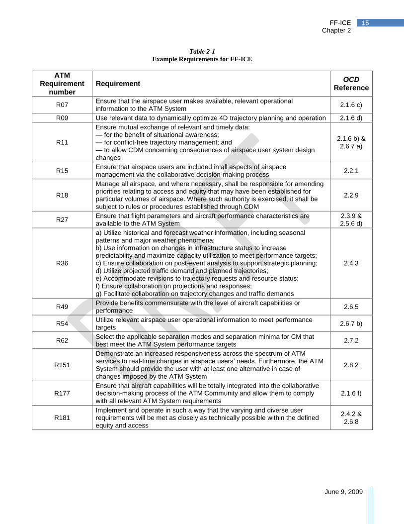
Although appendix A of this document gives a more detailed mapping to the requirements in 22
ICAO Document 9882, some example requirements listed in ICAO Document 9882 which are 23
relevant to the new functionality made available by the FF-ICE are identified here: 24
FF-ICE Chapter 2
June 9, 2009
15
Table 2-1
Example Requirements for FF-ICE
ATM Requirement
number Requirement
OCD Reference
R07 Ensure that the airspace user makes available, relevant operational information to the ATM System
2.1.6 c)
R09 Use relevant data to dynamically optimize 4D trajectory planning and operation 2.1.6 d)
R11
Ensure mutual exchange of relevant and timely data: — for the benefit of situational awareness; — for conflict-free trajectory management; and — to allow CDM concerning consequences of airspace user system design changes
2.1.6 b) & 2.6.7 a)
R15 Ensure that airspace users are included in all aspects of airspace management via the collaborative decision-making process
2.2.1
R18
Manage all airspace, and where necessary, shall be responsible for amending priorities relating to access and equity that may have been established for particular volumes of airspace. Where such authority is exercised, it shall be subject to rules or procedures established through CDM
2.2.9
R27 Ensure that flight parameters and aircraft performance characteristics are available to the ATM System
2.3.9 & 2.5.6 d)
R36
a) Utilize historical and forecast weather information, including seasonal patterns and major weather phenomena; b) Use information on changes in infrastructure status to increase predictability and maximize capacity utilization to meet performance targets; c) Ensure collaboration on post-event analysis to support strategic planning; d) Utilize projected traffic demand and planned trajectories; e) Accommodate revisions to trajectory requests and resource status; f) Ensure collaboration on projections and responses; g) Facilitate collaboration on trajectory changes and traffic demands
2.4.3
R49 Provide benefits commensurate with the level of aircraft capabilities or performance
2.6.5
R54 Utilize relevant airspace user operational information to meet performance targets
2.6.7 b)
R62 Select the applicable separation modes and separation minima for CM that best meet the ATM System performance targets
2.7.2
R151
Demonstrate an increased responsiveness across the spectrum of ATM services to real-time changes in airspace users’ needs. Furthermore, the ATM System should provide the user with at least one alternative in case of changes imposed by the ATM System
2.8.2
R177 Ensure that aircraft capabilities will be totally integrated into the collaborative decision-making process of the ATM Community and allow them to comply with all relevant ATM System requirements
2.1.6 f)
R181 Implement and operate in such a way that the varying and diverse user requirements will be met as closely as technically possible within the defined equity and access
2.4.2 & 2.6.8

FF-ICE Chapter 2
June 9, 2009
16
2.4 Benefits & Costs 1
The Manual on Global Performance of the Air Navigation System (ICAO Document 9883) 2
advocates that costs and benefits be addressed at the level of operational improvement; and 3
arguably it is not FF-ICE on its own that will deliver the operational improvements, but only 4
when used in conjunction with other processes still to be developed further, such as CDM and 5
SDM. This document does not provide a quantification of the costs and benefits to be derived 6
from the adoption and implementation of FF-ICE. 7
As advocated by Manual on Global Performance of the Air Navigation System (ICAO 8
Document 9883), members of the ATM Community will work – at local, regional, and global 9
levels – to develop transition roadmaps. These roadmaps are composed of specific operational 10
improvements, selected and sequenced to address performance gaps with respect to objectives 11
and targets derived from the ATM Community expectations. Guidelines of ICAO Document 12
9883 further advocate that these roadmaps be validated by a system-wide performance case, 13
from which the overall benefit of these operational improvements, enabled by FF-ICE, will 14
mature. (Reference ICAO Document 9883 paragraphs in Part I: Sections 1.4.1; 2.5.1; 2.5.3; 15
―performance case‖ definition, p.A-5; Section E.3.2.7. Reference paragraphs in Part II: Section 16
1.5.11; ―performance case‖ definition, p.11; ―validation‖ definition p.15; Sections 2.1; 2.3.2.2, 17
and 3.2.3.2). 18
FF-ICE Chapter 3
June 9, 2009
17
3 The FF-ICE Concept
In this Section, the FF-ICE concept is described detailing the following: 1
Principles – These are derived from The Global ATM Operational Concept and seek to 2
address the previously identified limitations. 3
Participants – The FF-ICE concept will require the interaction of multiple participants in 4
a collaborative environment. 5
Overall Collaborative Environment – This describes the information environment within 6
which the FF-ICE is expected to operate. 7
Timeline for FF-ICE information provision – The flight information process begins at a 8
time horizon up to a year before departure and continues until the completion of the 9
planned flight. 10
Scheduled Flight Scenario – An example of the flight information process is provided to 11
help the reader. 12
Formation Flights – The example of formation flights is provided to clarify how these are 13
to be treated in the FF-ICE. 14
3.1 Principles 15
The FF-ICE is guided by the requirement to eliminate or reduce the limitations of the present 16
Flight Plan and to accommodate the future detailed in the Global ATM Operational Concept 17
(ICAO Document 9854). 18
Principles of the FF-ICE can be summarized as follows: 19
Provide a flexible concept that allows new technologies and procedures to be 20
incorporated as necessary in a planned manner. This flexibility should also consider the 21
effects of evolving information and communications standards. 22
Allow aircraft to indicate their detailed performance capabilities, such as RNP level. 23
Allow for an early indication of intent. 24
Incorporate information for increased and more automated CDM. 25
Avoid unnecessary limitations on information. 26
Support four-dimensional management by trajectory. 27
Avoid the filing of unnecessary and unambiguously derivable information. Adopt a ―file-28
by-exception‖ philosophy when information can be standardized. 29
Allow for the provision of information security requirements. 30
Consider the cost impact on providers and consumers of flight information. 31
32
FF-ICE Chapter 3
June 9, 2009
18
Ensure information is machine readable and limit the need for free-text information. 1
Ensure that definitions of information elements for the FF-ICE are globally standardized. 2
Regional variation required for performance reasons will be implemented by use of 3
different subsets of the standard information elements. New elements will be introduced 4
regionally through regional extensions as needed but will not be mandatory for other 5
regions, will not provide duplicate information of existing elements, and should be 6
intended to become part of the global standard. A formal process will be introduced for 7
migrating successful new elements into the standard. 8
3.2 Participants 9
A future collaborative and dynamic flight information process requires the interaction of multiple 10
participants in the ATM Community. This list of participants is significantly extended from the 11
present day flight planning process as the process described herein begins a year prior to 12
departure and extends until completion of the planned flight. 13
A summary of the key high-level participants and roles is described below. Except emergency 14
service provider, the other terms are mentioned and/or described in detail in the Global ATM 15
Operational Concept (ICAO Document 9854), Appendix A. 16
Airspace Users (AU) – The term airspace users mainly refers to the organizations 17
operating aircraft and their pilots. For this document, we emphasize that airspace users 18
include the flight operations centers (FOC) responsible for the strategic planning of a 19
flight and the entity responsible for the execution of a flight which is traditionally a flight 20
deck. 21
Aerodrome Operators (AOP) – Participating aerodrome operators include the operators of 22
the departure, arrival, alternate, and any other airports requiring or providing information 23
for planning purposes. Per ICAO Document 9854, aerodrome operators are a part of the 24
aerodrome community. 25
ATM Service Providers (ASP) – (See definition and examples in ICAO Document 9854). 26
There are many ATM services provided to an airspace user from the earliest strategic 27
planning through completion of a flight. Entities providing service or potentially 28
providing service to an airspace user can require or provide information. These can 29
include the ANSP within which the flight departs, transits or arrives, in addition to an 30
ANSP where the flight is expected to transit an area of interest. 31
Airspace Provider (AP) – Flights transiting through airspace may require permission 32
from an airspace provider. This term is described in ICAO Document 9854 as a role, 33
traditionally the responsibility of contracting states, which has undergone some evolution. 34
Emergency Service Provider (ESP) – One important reason behind providing flight 35
information is to support the provision of emergency services in the event of such an 36
occurrence. Providers of these services require that certain information be available. 37
38
FF-ICE Chapter 3
June 9, 2009
19
3.3 Overall Collaborative Environment 1
It is recognized that a global environment will continue to have a variety of capabilities and 2
infrastructure; however, one goal is to provide for seamless interoperability despite some 3
remaining global disparities. The FF-ICE provides one opportunity to achieve part of this goal. 4
The FF-ICE concept provides a globally consistent process for planning and provision of 5
consistent flight information. Local design decisions may dictate that the underlying 6
mechanisms for the communication of flight information may not be identical; however, these 7
mechanisms must be compatible across boundaries and capable of exchanging required 8
information during all phases of flight planning. 9
The FF-ICE will be based on a globally consistent and unambiguous set of information elements. 10
The provision of consistent information does not imply that information requirements will be 11
identical globally. While the definition of flight information will be standardized globally, the 12
FF-ICE will contain some data elements that are required in one region and not in others. 13
Practically, this implies a need for an infrastructure to support the transport of this information. 14
In addition, not all information elements are required for all flights depending on desired 15
performance levels. 16
With regards to the management of the information, ICAO Document 9854 (§2.9) describes 17
some key objectives that the future flight planning environment must also adhere to: 18
Information must be shared on a system-wide basis. (§2.9.5) 19
Pertinent information will be available when and where it is required. (§2.9.6) 20
Information may be personalized, filtered, and accessed, as needed. The initial quality of 21
the information will be the responsibility of the originator; subsequent handling will not 22
compromise its quality. (§2.9.8) 23
Information sharing can be adjusted to mitigate any proprietary concerns. (§2.9.9) 24
Information management will use globally harmonized information attributes. (§2.9.11) 25
Authority to access and populate information items will be controlled in accordance with a set of 26
rules known to the ATM Community. Users may have access to a subset of information within 27
the FF-ICE. These access rights are not static and may change as a function of time or status of 28
the flight/system. Rules will also depend on the specific instance of the FF-ICE (e.g., one 29
airspace user may not alter other users‘ information). 30
Once the FF-ICE is created, all interested and authorized parties will have access to the 31
information it contains. One service may provide information upon request. Another service 32
may provide updates as the information changes. These updates will be based upon criteria 33
specified by the information consumer. These criteria may require notification that a flight is no 34
longer applicable should the flight information change. 35
It is expected that for making changes to information, access rights to each part of the flight 36
information will be determined based upon the authority that each user has, given the state of the 37
flight. Mechanisms will be in place (e.g., data ―ownership‖) to manage information updates 38
from multiple authorized parties. User profiles will be applied to define default behavior for 39
access, authorization, and subscription to information. 40
FF-ICE Chapter 3
June 9, 2009
20
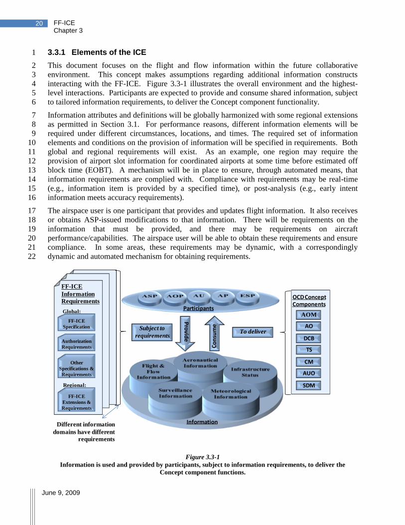
3.3.1 Elements of the ICE 1
This document focuses on the flight and flow information within the future collaborative 2
environment. This concept makes assumptions regarding additional information constructs 3
interacting with the FF-ICE. Figure 3.3-1 illustrates the overall environment and the highest-4
level interactions. Participants are expected to provide and consume shared information, subject 5
to tailored information requirements, to deliver the Concept component functionality. 6
Information attributes and definitions will be globally harmonized with some regional extensions 7
as permitted in Section 3.1. For performance reasons, different information elements will be 8
required under different circumstances, locations, and times. The required set of information 9
elements and conditions on the provision of information will be specified in requirements. Both 10
global and regional requirements will exist. As an example, one region may require the 11
provision of airport slot information for coordinated airports at some time before estimated off 12
block time (EOBT). A mechanism will be in place to ensure, through automated means, that 13
information requirements are complied with. Compliance with requirements may be real-time 14
(e.g., information item is provided by a specified time), or post-analysis (e.g., early intent 15
information meets accuracy requirements). 16
The airspace user is one participant that provides and updates flight information. It also receives 17
or obtains ASP-issued modifications to that information. There will be requirements on the 18
information that must be provided, and there may be requirements on aircraft 19
performance/capabilities. The airspace user will be able to obtain these requirements and ensure 20
compliance. In some areas, these requirements may be dynamic, with a correspondingly 21
dynamic and automated mechanism for obtaining requirements. 22
Figure 3.3-1
Information is used and provided by participants, subject to information requirements, to deliver the
Concept component functions.
Global:
Regional:
FF-ICE
Information
RequirementsOCD Concept Components
FF-ICE
Specification
Authorization
Requirements
Other
Specifications &
Requirements
FF-ICE
Extensions &
Requirements
AOM
AO
DCB
TS
CM
AUO
SDM
Co
nsu
me
Pro
vide
Participants
InformationDifferent information
domains have different
requirements
Subject to
requirementsTo deliver

FF-ICE Chapter 3
June 9, 2009
21
In order to perform many of the activities required to achieve the vision in the Global ATM 1
Operational Concept, flight and flow information must interact with aeronautical information to 2
deliver certain services required by multiple members of the ATM Community. Not all services 3
will be required by all members of the ATM Community and all services will not be provided by 4
all ASPs. 5
Figure 3.3-2 illustrates a few interactions, with these and more described below. 6
Flight information will refer to aeronautical information (e.g., this could be expressed in 7
Aeronautical Information Exchange Model [AIXM] format). This includes static 8
information such as runways, airports, and fixed boundaries. Aeronautical information 9
can also be dynamic as described below. 10
AOM allows the dynamic definition of airspace constructs such as airspace volumes and 11
routes. This will be dynamically reflected in aeronautical information. These must be 12
shared in such a way that flight information can reference the dynamic data and verify 13
that flights meet required constraints. 14
DCB requires the ability to communicate resource limitations (capacity) such that 15
projected resource utilization (demand) can be evaluated against it. Capacity-limited 16
resources are expressed within aeronautical information and the dynamic capacity figures 17
must be defined for these resources. This information must allow a proposed flight to be 18
evaluated to determine whether it contributes to demand/capacity imbalances. The 19
evaluation of a flight against congestion may include the probability of the flight 20
encountering congestion. This evaluation can be conducted by the airspace user. 21
Capacity will be impacted by the operational status of systems and infrastructure. The 22
ATM System requires the capacity impacts expressed in a manner consistent with 23
aeronautical information. 24
AUO will face requirements on performance and/or approved capabilities, both static and 25
dynamic. Some of these requirements are expected to be linked to aeronautical 26
information. For example, certain airspace volumes or routes (where defined) will 27
require levels of navigation performance. A mechanism must exist to specify and 28
disseminate these requirements. These requirements may also be altered as a result of 29
AOM activities. 30
Specifications on providing required information for the FF-ICE will also be expressed 31
using aeronautical information. For example, levels of precision required for trajectory 32
information provision can be dynamic and dependent on airspace constructs such as 33
routing. Requirements may also vary regionally based upon circumstances and desired 34
performance levels. 35

FF-ICE Chapter 3
June 9, 2009
22
Figure 3.3-2
Example dependencies between information and delivery of Demand/Capacity Balancing and Airspace
Organization and Management Concept Components
Planning of AUOs and AOs requires knowledge of weather (e.g., winds, convective activity, 1
instrument conditions). Weather also impacts the capacity of shared resources that must be 2
incorporated into tactical DCB. A shared situational awareness of weather information and its 3
projected impact on capacity is expected in the future collaborative environment. This situation 4
is illustrated in Figure 3.3-3. 5
Trajectory synchronization activities obtain flight information and provide constraints onto the 6
flight trajectory to achieve flow objectives and to conduct strategic CM. Trajectory 7
synchronization must consider the totality of the ATM situation including dynamic aeronautical 8
information, weather and infrastructure status as illustrated in Figure 3.3-4. 9
Figure 3.3-3
Example dependencies between information and delivery of Airspace User Operations Concept Component.
FF-ICE
references AI
information
AUO requires meteo and
infrastructure status
AUO requires
constraints and
airspace
information
AUO updates FF
Information

FF-ICE Chapter 3
June 9, 2009
23
Figure 3.3-4
Example dependencies between information and delivery of Traffic Synchronization Concept Component
Separation provision activities will be conducted by the designated separator, which may be an 1
ASP or the airspace user. In a trajectory-based environment, this activity operates on the 2
4D trajectory supplied as part of flight information, supplemented with up-to-date surveillance 3
information. Separation provision must also consider the totality of the ATM situation, 4
including dynamical aeronautical information, weather, and infrastructure status as shown in 5
Figure 3.3-5. 6
Figure 3.3-5
Example dependencies between information and delivery of Conflict Management Concept Component
FF-ICE
references AI
TS may provide
constraints on
trajectory in FF-ICE
TS requires meteo,
infrastructure status,
aeronautical information
and trajectories
FF-ICE
references AI
CM provides
separation
instructions
CM requires
information from
many sources

FF-ICE Chapter 3
June 9, 2009
24
3.4 Timeline for FF-ICE Information Provision 1
In the future, providing flight information for planning purposes will be a more ongoing process 2
relative to the present day. Whereas currently an aircraft operator may file a single FPL form, in 3
the future, the operator will provide increasing information about a flight as time approaches 4
departure and throughout the flight. Some of this information is known ahead of time with 5
relative certainty (e.g., departure and arrival airport), other information will be better known 6
closer to departure (e.g., route of flight, estimated time en-route), and some could change 7
dynamically throughout the flight (e.g., estimated time of departure, agreed trajectory). 8
Since the flight information process is expected to be ongoing, requirements for the provision of 9
information will be event-driven. These can include certain events such as: the availability of a 10
significant piece of data such as weather, a fixed time before scheduled pushback, a time prior to 11
entry into airspace, the issuance of a clearance, or a change in responsibility. One example of an 12
information provision requirement would be that before departure, the airspace user shall supply 13
information necessary for the provision of emergency services. 14
Throughout the flight information process, various participants will interact with the FF-ICE. 15
These will change along the flight information provision timeline with more strategic functions 16
(DCB) being involved earlier and more tactical functions (e.g., TS and CM) later. Figure 3.4-1 17
illustrates the types of activities relative to the events affecting a single flight. 18
Figure 3.4-1 Timeline of information provision relative to events pertaining to a single flight. Referenced Sections detail
FF-ICE activities in more detail.
Initial information provision may occur at any point along the timeline. For example, differing 19
airspace users may have different planning horizons as described in Section 3.4.5. This initial 20
information will be provided through a designated point-of-entry (POE, see Section 4.3.1.5) and 21
to an ASP typically applicable to the flight‘s departure point. Some ASPs may accommodate 22
multiple POEs, and some ASPs may accommodate the receipt of initial flight information from 23
Off-block
Taxi out
Takeoff
Taxi in
Touch-down In-block
1 year months 1 day hours
Scheduling & Strategic
Activities § 3.4.1
Pre-Tactical Operational
Planning § 3.4.2
Tactical Operational Planning
§ 3.4.3
Flight Operations § 3.4.4
Schedule
Weather,
Winds, Special Use Airspace,
Airframes known
FF-ICE Chapter 3
June 9, 2009
25
POEs not explicitly associated with a flight‘s departure point. Clarity regarding responsibility 1
for information is aided by information audit trails. 2
This ongoing flight information process can also be described in terms of a timeline of related 3
and interacting activities being performed by the various participants (see Figure 3.4-2 below). 4
The timeline employs language from the Global ATM Operational Concept (ICAO 5
Document 9854) and illustrates the times at which Concept components are employed to deliver 6
a single flight. 7
The figures describe the timeline for a scheduled flight operating through multiple ASPs with the 8
following important points: 9
The various ASPs encountered will be conducting activities to deliver various Concept 10
components at different points in time. For example, tactical DCB activities will not 11
necessarily occur at the same time for the departing and arrival ASP. 12
While it is recognized that many of the Concept components will be executed through 13
collaboration between multiple participants, Figure 3.4-2 illustrates the dominant 14
participants in each component. 15
Collaboration to realize each component will occur through the sharing of information 16
among participants. 17
Requirements will be levied on participants to supply specific information by certain 18
deadlines tied to events. 19
The FF-ICE will continue to be updated dynamically throughout the operation of a flight. 20
The timeline for flight information will be governed by the availability and quality of 21
information. A summary follows: 22
Planning activities for a flight begin before the development of a schedule. Collaboration 23
on demand levels, airspace permissions, and planned aerodrome and airspace capacity 24
levels allow decisions to be made on an initial flight schedule. 25
Knowledge of scheduled operations allows additional capacity management and airspace 26
organization. Initial schedules can be modified. 27
As operational constraints (e.g., weather, winds) become known, more detailed 28
information on a flight can be provided including route of flight and information required 29
for SAR. 30
After departure, flight information can continually be updated as a result of changing 31
conditions or operational impacts. 32
Post-arrival, information can be archived to support performance reporting necessary for 33
a performance-based ATM System as envisaged in the Global ATM Operational Concept 34
and the Manual on Global Performance of the Air Navigation System. 35
The timeline for an example flight is described below in greater detail in terms of the activities 36
shown in Figure 3.4-1. The effect of the user types on the timeline is described in Section 3.4.5. 37 38

FF-ICE Chapter 3
June 9, 2009
26

FF-ICE Chapter 3
June 9, 2009
27
3.4.1 Scheduling and Strategic Activities 1
The provision of long-term intent, when available, is consistent with the Global ATM 2
Operational Concept calling for users to supply long-term intent information for the purposes of 3
identifying imbalances. Advanced intent information can also be used for airport operations, 4
military operations, and diplomatic clearances. This can occur as far as one year before 5
departure, at which point not all flight planning information needs to be provided. As a flight 6
approaches and confidence is gained in the information, then additional fields may be populated. 7
As a result of AUO mission planning, airspace users with a longer planning horizon supply the 8
type of information commonly found in schedules today (e.g., origin, destination, aircraft type 9
and times of arrival/departure). The information from many flights is used as part of strategic 10
DCB to collaboratively determine acceptable schedules and to plan to deliver a level of 11
performance (including capacity) consistent with the anticipated demand. Provided information 12
will be used for AOM, planning activities for AO and providing airspace permissions. 13
It is expected that ASPs will determine their demand by the use of a combination of historical 14
information, expected growth patterns, information from special events (e.g., large sporting or 15
cultural events causing changes in traffic patterns), and early FF-ICE information. This early 16
information will thus be used as a refinement of the other information, but is not expected to 17
replace it as the sole source of demand information. 18
Airspace user-provided information is subject to change as information becomes known with 19
greater certainty closer to departure. Operators providing this information are expected to update 20
it as more accurate planning information becomes available. Flight information will be updated 21
by referencing a global common identifier for a flight. 22
Airspace users may wish to provide information for flights which will operate in the same 23
manner on a repeated basis. This is acceptable provided that all information required is provided 24
and correct. However, in certain environments, system performance considerations may require 25
a greater level of interaction and flight information customization. 26
Nothing precludes an operator from supplying more information at an earlier point in the 27
timeline. ASPs should consider the impact methods which alter the time at which users are 28
motivated to file have on ATM System Performance. 29
3.4.2 Pre-tactical Operational Planning 30
At some point before departure, demand and traffic flow patterns begin to crystallize. At this 31
time, a plan can be developed taking account of the information that is known. However, the 32
specific operational conditions (e.g., weather, winds, system outages, maintenance issues) are not 33
known precisely. The development of this plan is the role of the pre-tactical stage of demand-34
capacity balancing envisaged in the Global ATM Operational Concept. The pre-tactical DCB 35
provides a plan to be followed if no tactical disturbances are encountered. As described in the 36
Operational Concept: 37
At the pre-tactical stage, demand and capacity balancing will evaluate the current 38
allocation of ASP, airspace user, and aerodrome operator assets and resources against 39
the projected demands. Through CDM, when possible, adjustments will be made to 40
assets, resource allocations, projected trajectories, airspace organization, and allocation 41
of entry/exit times for aerodromes and airspace volumes to mitigate any imbalances. 42
FF-ICE Chapter 3
June 9, 2009
28
Collaboration occurs between AUO, AO, Demand and Capacity Balancing and AOM resulting 1
in refinement of the FF-ICE information previously provided. Other types of information (e.g., 2
aeronautical information and access requirements) may also be changing. 3
3.4.3 Tactical Operational Planning 4
Closer to the flight operation time, the ATM System has access to more accurate planning 5
information such as weather, specific airframe availability, winds, resource demand, equipment 6
outages, and requirements on military operations areas. AOs can provide weather-influenced 7
airport capacity and configuration forecasts. AOM can respond to these updated conditions (e.g., 8
convective weather, military activity). 9
As a result of this improved source information, AUOs refine previously provided information 10
and provide new information previously not known. Examples include: 11
Improved forecasting of departure times as the status of inbound aircraft become known 12
Better estimated times en route as wind information is known 13
Precise knowledge of airframe to be used and flight capability 14
Explicit knowledge of the desired route of flight to incorporate winds, avoidance of 15
restricted airspace and convective weather areas 16
Knowledge of information necessary to generate desired 4D trajectories 17
The accuracy of information will continue to increase as the forecast horizon decreases. The 18
impact of the improved information will be evaluated by participants and information will be 19
updated as appropriate. Updates will continue throughout flight operation. 20
The tactical planning phase of DCB continues to collaboratively adjust the 4D trajectory to 21
ensure system resources are not overloaded. As part of the collaborative SWIM environment, 22
participants will have access to consistent and continuously updated information regarding 23
expected constraints in the system. This timely access to such information will enable both 24
operators and service providers to take action (e.g., request a re-route or be offered access) as 25
new information becomes available. This collaborative process is expected to enable 26
optimization of 4D trajectories. Information contained within the FF-ICE will support the 27
collaboration and performance objectives. 28
Editorial Note - A detailed example of a collaborative process during tactical operational 29
planning will be provided in the next version of this document. 30
Information supporting ESPs (e.g., SAR information) is available at this time. Strategic CM and 31
TS may begin to occur before departure resulting in the imposition of constraints and tolerances 32
on the 4D trajectory. 33
Some of the tactical operational planning activities continue as the flight operates, such as 34
replanning to accommodate dynamic constraints. However, certain minimum information will 35
be required before flight operation. Local performance requirements may require stability on the 36
information for some time period before departure or entry into a region. 37

FF-ICE Chapter 3
June 9, 2009
29
3.4.4 Flight Operation 1
Once the flight has begun operation, FF-ICE information continues to be shared among the 2
relevant participants of the ATM Community. Information contained in the FF-ICE forms the 3
basis of the agreed 4D trajectory, upon which tactical decisions are made. For this reason, it is 4
necessary that this information be current. This is accomplished through updates to the FF-ICE 5
and may occur for a variety of reasons as follows: 6
Tactical control – For certain ASPs, tactical controllers may take actions on the flight, 7
leading to changes in the FF-ICE in support of CM or TS. This may include the 8
assignment of altitudes, speeds or local changes to routing. These can impact the 9
downstream agreed 4D trajectory and must be updated to allow downstream ―pre-10
tactical‖ DCB planning to occur. 11
Changing constraints – Constraints may appear or relax compared to an earlier forecast 12
(e.g., weather deteriorates or improves over forecast, a military training area becomes 13
available or not, etc.). Through a collaborative process, the flight and associated FF-ICE 14
can be altered to accommodate the new constraints. The collaboration process may be 15
triggered by either the service provider or the operator, and may be real-time interactive 16
(either an iterative exchange between fully-automated systems, or with human in-the-17
loop), or based on operator preferences, which may be defined by conditional rules or 18
priority, and may vary for each individual flight. 19
Dynamic demand – As operations proceed and forecasts change, forecast demand may 20
change, leading to lower or higher than expected demand. Again, a collaborative process 21
seeks to accommodate the constraints subject to meeting operators‘ preferences in an 22
equitable manner. 23
Known information – Certain information will only become known with certainty at later 24
points in time. For example, this may include the arrival runway information and the 25
arrival route in the terminal area. This information will be updated as the information 26
becomes available. 27
Transfer of Control – Flights may progress through various regions with differing 28
performance and service levels (see Section 4.4.1.2). 29
While increased collaboration is expected, it is recognized that the need for immediate tactical 30
decisions will result in collaboration being curtailed at some point in accordance with known 31
rules of conduct. These rules will have been pre-established using a collaborative process. 32
33
FF-ICE Chapter 3
June 9, 2009
30
3.4.5 Effect of User Type on Timeline 1
While information provision is expected to be event-generated, it is recognized that there are a 2
variety of categories of airspace users and they may be responding to internal events consistent 3
with their own business or mission objectives. As an example, we consider the main events 4
during the planning and execution of a flight viewed from the perspective of three types of 5
airspace users (there may be other airspace users not identified here, e.g., air-filers): 6
Airspace User who is a Seasonal Planner. This is the type of airspace user who decides 7
to fly more than a month before the flight will take place; for example, an airline. From 8
this type of airspace user, useful early information about the flight intentions could be 9
obtained well in advance of the date of flight and be used by ASPs to refine their traffic 10
forecasts, strategic plans, controller rosters, etc. When using a coordinated airport, this 11
type of airspace user may have to wait until the airport slots are available before 12
providing certain information items. 13
Airspace User who is a Medium-Term Planner. This is the type of airspace user who 14
decides to fly between one day to one month before the flight will take place; for 15
example, a charter operator or certain military airspace users. Information cannot be 16
provided by this type of airspace user as early as Seasonal Planners, but some useful 17
information should be available before the day of flight. 18
On Demand Airspace User. This is the type of airspace user who decides to fly within 19
the last 24 hours before the flight; for example, a business jet, air taxi, or certain types of 20
military airspace user. Early information cannot be provided by such AUs because they 21
simply do not know when or where they will fly until the day of flight. Thus, their initial 22
submission will have to contain significantly more information. 23
The flight information provided by all types of airspace user is expected to evolve by means of 24
an iterative process throughout the period from initial submission until termination of the flight. 25
Table 3.4-1 illustrates, through an example, the timeline of events and type of information 26
provided by the different types of airspace users. 27
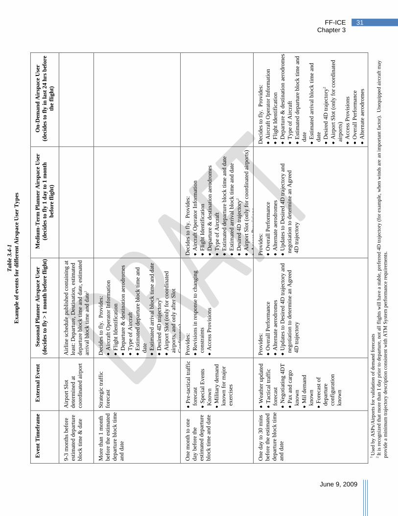
FF-ICE Chapter 3
June 9, 2009
31
On
-Dem
an
d A
irsp
ace
Use
r
(dec
ides
to
fly
in
la
st 2
4 h
rs b
efo
re
the
flig
ht)
Dec
ides
to
fly
. P
rov
ides
:
Air
craf
t O
per
ato
r In
form
atio
n
Fli
gh
t Id
enti
fica
tion
Dep
artu
re &
des
tin
atio
n a
erod
rom
es
Ty
pe
of
Air
craf
t
Est
imat
ed d
epar
ture
blo
ck t
ime
and
dat
e
Est
imat
ed a
rriv
al b
lock
tim
e an
d
dat
e
Des
ired
4D
tra
ject
ory
2
Air
po
rt S
lot
(on
ly f
or
coo
rdin
ated
airp
ort
s)
Acc
ess
Pro
vis
ion
s
Ov
eral
l P
erfo
rman
ce
Alt
ern
ate
aero
dro
mes
Med
ium
-Ter
m P
lan
ner
Air
spa
ce U
ser
(dec
ides
to
fly
1 d
ay
to 1
mon
th
bef
ore
fli
gh
t)
Dec
ides
to
fly
. P
rov
ides
:
Air
craf
t O
per
ato
r In
form
atio
n
Fli
gh
t Id
enti
fica
tion
Dep
artu
re &
des
tin
atio
n a
erod
rom
es
Ty
pe
of
Air
craf
t
Est
imat
ed d
epar
ture
blo
ck t
ime
and
dat
e
Est
imat
ed a
rriv
al b
lock
tim
e an
d d
ate
Des
ired
4D
tra
ject
ory
2
Air
po
rt S
lot
(on
ly f
or
coo
rdin
ated
air
po
rts)
Acc
ess
Pro
vis
ion
s
Pro
vid
es:
Ov
eral
l P
erfo
rman
ce
Alt
ern
ate
aero
dro
mes
Up
dat
es t
o D
esir
ed 4
D t
raje
cto
ry a
nd
neg
oti
atio
n t
o d
eter
min
e an
Ag
reed
4D
tra
ject
ory
Sea
son
al
Pla
nn
er A
irsp
ace
Use
r
(dec
ides
to
fly
> 1
mo
nth
bef
ore
fli
gh
t)
Air
lin
e sc
hed
ule
pu
bli
shed
con
tain
ing
at
leas
t: D
epar
ture
, D
esti
nat
ion
, es
tim
ated
dep
artu
re b
lock
tim
e an
d d
ate,
est
imat
ed
arri
val
blo
ck t
ime
and
dat
e1
Dec
ides
to
fly
. P
rov
ides
:
Air
craf
t O
per
ato
r In
form
atio
n
Fli
gh
t Id
enti
fica
tion
Dep
artu
re &
des
tin
atio
n a
erod
rom
es
Ty
pe
of
Air
craf
t
Est
imat
ed d
epar
ture
blo
ck t
ime
and
dat
e
Est
imat
ed a
rriv
al b
lock
tim
e an
d d
ate
Des
ired
4D
tra
ject
ory
2
Air
po
rt S
lot
(on
ly f
or
coo
rdin
ated
airp
ort
s, a
nd
on
ly a
fter
Slo
t
Co
nfe
ren
ce)
Pro
vid
es:
Rev
isio
ns
in r
espo
nse
to
ch
ang
ing
con
stra
ints
Acc
ess
Pro
vis
ion
s
Pro
vid
es:
Ov
eral
l P
erfo
rman
ce
Alt
ern
ate
aero
dro
mes
Up
dat
es t
o D
esir
ed 4
D t
raje
cto
ry a
nd
neg
oti
atio
n t
o d
eter
min
e an
Ag
reed
4D
tra
ject
ory
Ex
tern
al
Ev
ent
Air
po
rt S
lot
det
erm
ined
at
coo
rdin
ated
air
po
rt
Str
ateg
ic t
raff
ic
fore
cast
Pre
-tac
tica
l tr
affi
c
fore
cast
Sp
ecia
l E
ven
ts
Kn
ow
n
Mil
itar
y d
eman
d
kn
ow
n f
or
maj
or
exer
cise
s
Wea
ther
upd
ated
Tac
tica
l tr
affi
c
fore
cast
Neg
oti
atin
g 4
DT
Pax
an
d c
arg
o
kn
ow
n
Mil
dem
and
kn
ow
n
Fo
reca
st o
f
dep
artu
re
con
figu
rati
on
kn
ow
n
Ev
ent
Tim
efra
me
9-3
mon
ths
bef
ore
esti
mat
ed d
epar
ture
blo
ck t
ime
& d
ate
Mo
re t
han
1 m
on
th
bef
ore
th
e es
tim
ated
dep
artu
re b
lock
tim
e
and
dat
e
On
e m
on
th t
o o
ne
day
bef
ore
th
e
esti
mat
ed d
epar
ture
blo
ck t
ime
and
dat
e
On
e d
ay t
o 3
0 m
ins
bef
ore
th
e es
tim
ated
dep
artu
re b
lock
tim
e
and
dat
e
1 U
sed
by A
SP
s/A
irp
ort
s fo
r val
idat
ion
of
dem
and
fo
reca
sts
2 It
is
reco
gn
ized
that
mo
re t
han
1 d
ay p
rio
r to
dep
artu
re, no
t al
l fl
ights
wil
l h
ave
a st
able
, p
refe
rred
4D
tra
ject
ory
(fo
r ex
amp
le,
wh
en w
ind
s ar
e an
im
po
rtan
t fa
cto
r).
Un
equip
ped
air
craf
t m
ay
pro
vid
e a
min
imu
m t
raje
cto
ry d
escr
ipti
on c
on
sist
ent
wit
h A
TM
Sy
stem
per
form
ance
req
uir
emen
ts.
Ta
ble
3.4
-1
Ex
am
ple
of
even
ts f
or
dif
fere
nt
Air
spa
ce U
ser
Ty
pes
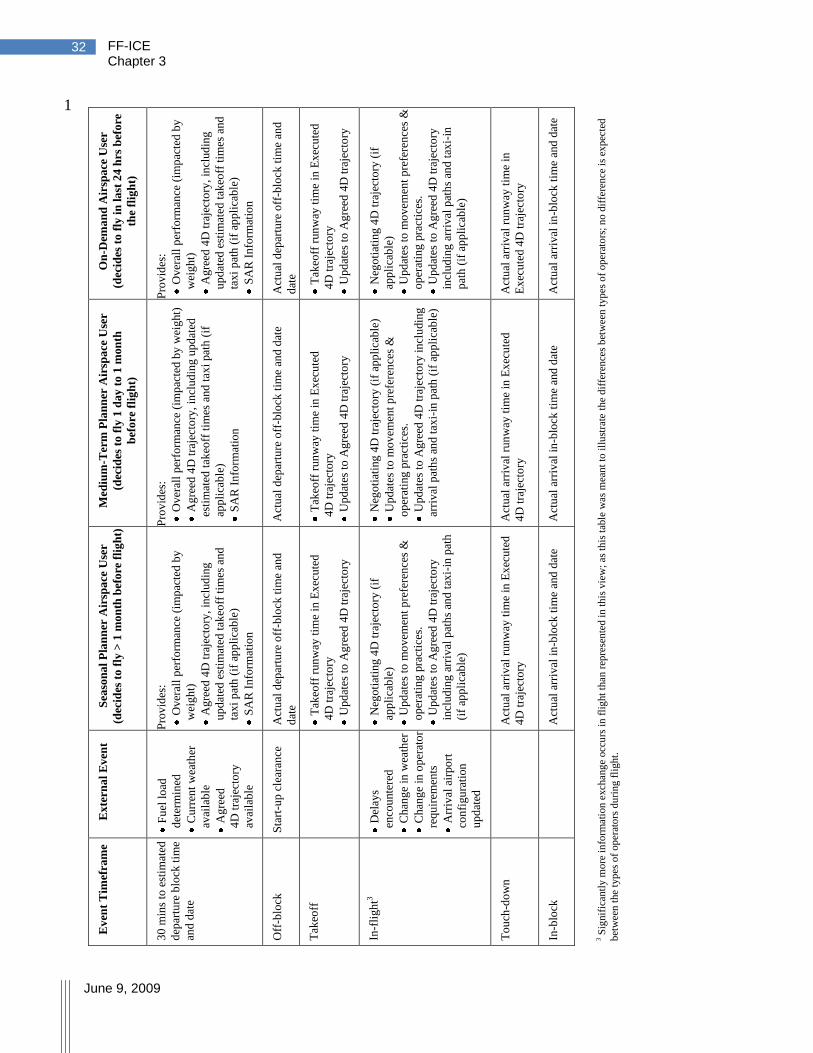
FF-ICE Chapter 3
June 9, 2009
32
1 O
n-D
ema
nd
Air
spa
ce U
ser
(dec
ides
to
fly
in
la
st 2
4 h
rs b
efo
re
the
flig
ht)
Pro
vid
es:
Ov
eral
l p
erfo
rman
ce (
imp
acte
d b
y
wei
gh
t)
Ag
reed
4D
tra
ject
ory
, in
clud
ing
up
dat
ed e
stim
ated
tak
eoff
tim
es a
nd
tax
i p
ath
(if
ap
pli
cab
le)
SA
R I
nfo
rmat
ion
Act
ual
dep
artu
re o
ff-b
lock
tim
e an
d
dat
e
Tak
eoff
run
way
tim
e in
Ex
ecu
ted
4D
tra
ject
ory
Up
dat
es t
o A
gre
ed 4
D t
raje
cto
ry
Neg
oti
atin
g 4
D t
raje
cto
ry (
if
app
lica
ble
)
Up
dat
es t
o m
ov
emen
t p
refe
ren
ces
&
op
erat
ing
pra
ctic
es.
Up
dat
es t
o A
gre
ed 4
D t
raje
cto
ry
incl
ud
ing
arr
ival
pat
hs
and
tax
i-in
pat
h (
if a
pp
lica
ble
)
Act
ual
arr
ival
run
way
tim
e in
Ex
ecu
ted
4D
tra
ject
ory
Act
ual
arr
ival
in
-blo
ck t
ime
and
dat
e
Med
ium
-Ter
m P
lan
ner
Air
spa
ce U
ser
(dec
ides
to
fly
1 d
ay
to 1
mon
th
bef
ore
fli
gh
t)
Pro
vid
es:
Ov
eral
l p
erfo
rman
ce (
imp
acte
d b
y w
eig
ht)
Ag
reed
4D
tra
ject
ory
, in
clud
ing
up
dat
ed
esti
mat
ed t
akeo
ff t
imes
an
d t
axi
pat
h (
if
app
lica
ble
)
SA
R I
nfo
rmat
ion
Act
ual
dep
artu
re o
ff-b
lock
tim
e an
d d
ate
Tak
eoff
run
way
tim
e in
Ex
ecu
ted
4D
tra
ject
ory
Up
dat
es t
o A
gre
ed 4
D t
raje
cto
ry
Neg
oti
atin
g 4
D t
raje
cto
ry (
if a
pp
lica
ble
)
Up
dat
es t
o m
ov
emen
t p
refe
ren
ces
&
op
erat
ing
pra
ctic
es.
Up
dat
es t
o A
gre
ed 4
D t
raje
cto
ry i
ncl
udin
g
arri
val
pat
hs
and
tax
i-in
pat
h (
if a
pp
lica
ble
)
Act
ual
arr
ival
run
way
tim
e in
Ex
ecu
ted
4D
tra
ject
ory
Act
ual
arr
ival
in
-blo
ck t
ime
and
dat
e
Sea
son
al
Pla
nn
er A
irsp
ace
Use
r
(dec
ides
to
fly
> 1
mo
nth
bef
ore
fli
gh
t)
Pro
vid
es:
Ov
eral
l p
erfo
rman
ce (
imp
acte
d b
y
wei
gh
t)
Ag
reed
4D
tra
ject
ory
, in
clud
ing
up
dat
ed e
stim
ated
tak
eoff
tim
es a
nd
tax
i p
ath
(if
ap
pli
cab
le)
SA
R I
nfo
rmat
ion
Act
ual
dep
artu
re o
ff-b
lock
tim
e an
d
dat
e
Tak
eoff
run
way
tim
e in
Ex
ecu
ted
4D
tra
ject
ory
Up
dat
es t
o A
gre
ed 4
D t
raje
cto
ry
Neg
oti
atin
g 4
D t
raje
cto
ry (
if
app
lica
ble
)
Up
dat
es t
o m
ov
emen
t p
refe
ren
ces
&
op
erat
ing
pra
ctic
es.
Up
dat
es t
o A
gre
ed 4
D t
raje
cto
ry
incl
ud
ing
arr
ival
pat
hs
and
tax
i-in
pat
h
(if
app
lica
ble
)
Act
ual
arr
ival
run
way
tim
e in
Ex
ecu
ted
4D
tra
ject
ory
Act
ual
arr
ival
in
-blo
ck t
ime
and
dat
e
Ex
tern
al
Ev
ent
Fu
el l
oad
det
erm
ined
Cu
rren
t w
eath
er
avai
lab
le
Ag
reed
4D
tra
ject
ory
avai
lab
le
Sta
rt-u
p c
lear
ance
Del
ays
enco
unte
red
Ch
ang
e in
wea
ther
Ch
ang
e in
op
erat
or
req
uir
emen
ts
Arr
ival
air
po
rt
con
figu
rati
on
up
dat
ed
Ev
ent
Tim
efra
me
30
min
s to
est
imat
ed
dep
artu
re b
lock
tim
e
and
dat
e
Off
-blo
ck
Tak
eoff
In-f
ligh
t3
To
uch
-do
wn
In-b
lock
3 S
ignif
ican
tly
mo
re i
nfo
rmat
ion
exch
ang
e occ
urs
in
fli
ght
than
rep
rese
nte
d i
n t
his
vie
w;
as t
his
tab
le w
as m
ean
t to
ill
ust
rate
the
dif
fere
nce
s b
etw
een
typ
es o
f op
erat
ors
; n
o d
iffe
ren
ce i
s ex
pec
ted
bet
wee
n t
he
typ
es o
f op
erat
ors
du
ring
fli
ght.

FF-ICE Chapter 3
June 9, 2009
33
3.5 Scheduled Flight Scenario 1
This section presents a high-level scenario describing the evolution of the information for a 2
scheduled flight. The high-level scenario is broken into smaller scenarios, described in more 3
detail in appendix C. These smaller scenarios are described through interaction between the 4
participants identified in section 3.2. The overall relationship between these scenarios is 5
illustrated in Figure 3.5-1. The activities are loosely organized in time, but there is no specific 6
time order to many of the activities described. For example, while initial information provision 7
must occur first, and some activities must occur before or after departure, many activities may 8
occur in any order. 9
For clarity, appendix C defines interactions mostly with a single ASP. It is recognized that 10
multiple ASPs may be involved throughout the flight‘s lifecycle. It is assumed that the functions 11
performed by a single ASP will also be conducted across multiple ASPs by sharing information 12
pertinent to applicable portions of a flight‘s 4D trajectory. An example is provided in 13
Appendix C, Section C.7, Negotiation Across Multiple ASPs. 14

FF-ICE Chapter 3
June 9, 2009
34
Figure 3.5-1
Role of participants in various scenarios throughout a flight’s evolution
AU ASP AOP AP ESP
Provide Initial Information
Provides Info Verifies, accepts,
publishes, assigns
GUFI
Strategic Planning
Adjusts
Schedule
Provides capacity
Manages resources
Specifies requirements
Provides Capacity &
Aerodrome
Constraints
Permission Provision & Verification
Requests
Permissions Verifies
Provides
Permissions
Additional Information Provision Prior to Departure day
Provide preferences &
(initial) desired 4DT
Include requirements
DCB / AOM
Adjust requirements
Evaluation services
Provides Capacity &
Constraints
Provide Desired 4DT
Obtain meteo, airspace
& performance reqs., &
projected imbalances
Provide Desired 4DT
DCB / AOM
Adjust requirements
Evaluation Services
Provides Capacity &
Constraints
Obtain Agreed 4DT
Provide preferences
Modify 4DT
Agreed 4DT
Implement rules
Consider preferences
Verify compliance
Verify & notify
Provision of desired 4DT
is part of provision of
additional information
Constrain a Trajectory (for TS/ strategic CM)
Provide preferences
Evaluate proposal
Formulate alternative
TS/sCM - Propose
constrained 4DT
Provide requirements
If necessary, agreement
may require constraining
the 4DT
Including the Surface Segment
Provide preferences
Evaluate proposal
Formulate alternative
Develop & distribute
surface plan
Provide surface plan
requirements
Obtains SAR
Information
Provide SAR Information
Provide SAR
Information
Separation Provision
Respond
Alter the flight
Obtain surveillance
Develop instructions
& communicate
Scenario describes ground-
based role as separator –
concept supports airborne
separation

FF-ICE Chapter 3
June 9, 2009
35
3.5.1 Scheduling and Strategic Activities 1
Up to a year before operation, an airspace user determines that it wishes to operate a flight 2
between an origin and destination at a specified time and date. The airspace user provides this 3
information to an ASP responsible for initially managing the FF-ICE and a globally unique flight 4
identifier (GUFI, see Section 4.2.2.1) is obtained. This identifier ensures that all participants in 5
the ATM System can unambiguously refer to the information pertaining to a flight. The 6
available information can now be shared with authorized participants such as the affected ANSP, 7
airspace providers and aerodromes. This sharing is accomplished by notifying participants who 8
meet conditions for receiving notification. These conditions include: participants are authorized 9
to receive notification, and participants have requested information meeting criteria (e.g., flights 10
to a destination airport). Rules are in place to determine authorization and information security 11
measures are applied to enforce the rules. 12
Additional details are contained in Appendix C, Section C.2, Providing Initial 13
Information 14
In a performance-based environment, certain regions will require more stringent information 15
provision in order to achieve required performance levels. Airspace users will have access to 16
these requirements and, based upon the flight being planned, additional information will be 17
provided. This may include, among other things: 18
Aircraft type information for aerodrome gate planning 19
Aircraft wake performance for aerodrome capacity estimation 20
Navigation performance on departure or arrival at the requested aerodromes for capacity 21
estimation 22
Environmental performance levels for environmental management 23
Achievable departure and arrival time performance 24
Notified aerodromes and ASP use the provided information to conduct strategic DCB (DCB) and 25
related AOM (AOM) activities to deliver capacity where required. In some instances, demand 26
will exceed the maximum projected capacity for the day of operation. The FF-ICE supports 27
sharing the expected aggregate demand and capacity levels with participants. Using this 28
information for AUO mission planning, airspace users can adjust planned flights to alleviate 29
imbalances. Since this adjustment may not be sufficient, a collaborative approach will be used to 30
further adjust planned flights to ensure a level of demand consistent with achievable capacity. 31
Differing processes may exist across ASP with specific information requirements to support 32
them. The outcome of this process will be the schedule for the proposed flights. 33
Additional details are contained in Appendix C, Section C.3, Strategic Planning 34
Activities and Uses of Initial Information 35
As part of the planning for a flight, the airspace user will coordinate with airspace providers to 36
ensure that appropriate access permissions are obtained for the flight, where required. If 37
necessary, permission information will be provided as part of the FF-ICE as well. 38
Additional details are contained in Appendix C, Section C.4, Permission Provision and 39
Verification 40

FF-ICE Chapter 3
June 9, 2009
36
3.5.2 Pre-tactical Operational Planning 1
Once initial schedules have been provided and permissions have been obtained, additional 2
activities will be performed to accommodate demand. These activities include airspace 3
organization through the modification and imposition of airspace and route structures, and 4
development of staffing plans. Conducting these activities may require providing initial 5
trajectory information to estimate airspace demand. As airspace is organized and capacity limits 6
are better known, this information is provided through the collaborative environment. Services 7
are provided to allow the evaluation of compliance with dynamic requirements (e.g., a service to 8
ensure performance requirements are met for a specified trajectory) and to identify flights 9
impacted by capacity limitations. With this information, the airspace user may elect to modify 10
the proposed flight trajectory. 11
Additional details are contained in Appendix C, Section C.5, Providing Additional 12
Information Prior to Departure Day 13
3.5.3 Tactical Operational Planning 14
Approximately 24 hours before departure, information necessary for more precise planning 15
becomes available. This includes winds, weather, system outages, availability of trained crew, 16
and equipment status. A 4D trajectory is provided by the airspace user representing the desired 17
flight path (appendix D explains the trajectory in more detail). Additional information on 18
aircraft performance capabilities is provided in areas such as navigation, surveillance, 19
communication, separation assurance, safety-net, noise, emission, and wake. 20
Additional details are described in Appendix C, Section C.6.1, Provide Desired 21
4D trajectory 22
Negotiation occurs between the airspace user and other participants to obtain an agreed 23
4D trajectory. In this collaborative environment, the airspace user is dynamically aware of 24
required constraints, areas of capacity shortfall, and the rules for arbitration when time for 25
negotiation has expired. With this knowledge, the airspace user can adjust the trajectory to pick 26
the most optimal solution subject to the known constraints. Should this process not yield an 27
agreed trajectory at a required point in time, pre-collaborated rules will be imposed to obtain a 28
4D trajectory meeting performance objectives. These rules may consider airspace user-provided 29
preferences. 30
Additional details are described in Appendix C, Section C.6.2, Obtaining an Agreed 31
4D trajectory 32
The ASP will consider all available trajectory information to implement TS. TS is a continual, 33
dynamic process that imposes constraints on the negotiated trajectory to ensure no short-term 34
capacity imbalances occur, to ensure high throughput where resources are in high demand, and to 35
reduce the likelihood of conflicts. Initial TS will impose trajectory-specific constraints (e.g., 36
meeting a time) and tolerances on those constraints (e.g., how closely the time must be met) all 37
within the bounds of the aircraft performance limits. Together with the agreed trajectory, this 38
information represents the 4D trajectory contract (ICAO Document 9854, Appendix I, §6.14). 39
This is described in more detail in Appendix C, Section C.6.4, Constraining a 40
Trajectory 41

FF-ICE Chapter 3
June 9, 2009
37
Prior to departure, not all trajectory information will be supplied by the airspace user. For 1
example, the airspace user may be concerned with runway, pushback, and wheels-up times, but 2
would accommodate any valid taxi-path. The surface plan information would be obtained 3
through collaboration between the airspace user, the aerodrome operator and the ASP. Not all 4
aerodromes would require a surface plan in the trajectory. 5
Additional details are described in Appendix C, Section C.6.3, Including the Surface 6
Segment 7
Information required for emergency services is provided by the airspace user and shared with 8
authorized participants. 9
Additional details are described in Appendix C, Section C.6.5, Emergency Services 10
Information 11
When a flight is ready to receive a departure clearance, the above functions will have been 12
accomplished to the levels required by performance considerations. Practically, this means that: 13
All required access permissions have been obtained. 14
Constraints emanating from a collaborative DCB process are met. 15
Strategic CM and TS have occurred to the level of fidelity for pre-departure 16
consideration. 17
Where necessary, surface segments have been defined. 18
SAR information has been provided consistent with the proposed operation. 19
An agreed 4D trajectory has been obtained including the information items 20
commensurate with the proposed operation. 21
Upon verification of the above, the agreed 4D trajectory is updated to reflect the accurate 22
departure block time. This update may trigger a need to renegotiate the previous agreement. A 23
departure clearance is subsequently issued to begin delivering the agreed 4D trajectory. 24
3.5.4 Flight Operation 25
If applicable, the flight follows the taxi-out surface plan provided in the agreed 4D trajectory. 26
Positive instructions will be required to cross active runways. The taxi-out surface plan should 27
not be construed to represent a take-off clearance. Upon takeoff, the executed 4D trajectory in 28
the FF-ICE information will be updated to reflect the actual departure time. The agreed 29
4D trajectory times can also be updated by the airspace user provided the time updates are within 30
any agreed tolerances. Deviation from the agreed 4D trajectory indicates a need to reach a new 31
agreement. 32
Throughout the flight, the FF-ICE provides information necessary for separation provision and 33
for designation of the responsible separator and separation mode. Information on approvals for 34
airborne applications (e.g., limited delegated separation, autonomous separation) and 35
functioning, and approved equipment on-board will be contained in the flight information. 36
Levels of information supplied by the flight (e.g., broadcast trajectory intent) will be provided in 37
flight information, if so required. 38

FF-ICE Chapter 3
June 9, 2009
38
In environments where a performance-case warrants, separation provision will be based on 1
precise 4D trajectory information shared by relevant participants. When modifications to the 2
trajectory are required, the trajectory will be updated within the FF-ICE. The updated trajectory 3
is expected to be consistent across relevant airborne and ground-based platforms. 4
Appendix C, Section C.6.6, Information in Support of Separation Provision indicates 5
how the FF-ICE supports separation provision 6
Either the airspace user or the ASP may initiate a change to the 4D trajectory after departure, 7
thereby initiating the trajectory negotiation process. TS may trigger an update to the trajectory as 8
well. These updates continue throughout the flight as required to manage dynamic developments 9
and uncertainty. The persistence of TS and trajectory updates throughout an operational flight 10
will require that information be provided to/from the aircraft in support of these activities. 11
Addressing information must be supplied within the FF-ICE to allow this to occur. 12
Appendix C, Section C.6.4, Constraining a Trajectory 13
As the flight approaches arrival, information on descent, terminal area, and surface operations 14
will become more certain and will result in updates to the flight information, including the 15
trajectory. Taxi-in information may be provided. Activities in CM, TS, and tactical DCB will 16
continue. Upon arrival of the flight on-blocks, the executed 4D trajectory is complete. 17
Information is archived in accordance with requirements established by the performance process. 18
3.6 Formation Flights 19
To be controlled as a formation, the aircraft in the formation must be within a volume of 20
½ NM radius and 100ft height around the leader, unless otherwise specified in the FF-ICE 21
information for the formation (see below). A formation may consist of military and/or civil 22
aircraft, and the aircraft may be of heterogeneous types. The formation leader aircraft will be 23
identified to ATC for the purposes of control of the formation. 24
The FF-ICE Concept will support the possibility for aircraft to fly in a formation, and for the 25
formation to be controlled as a single entity, termed ‗ICE-Formation‘ and is defined below. 26
Each flight in the formation will have its own FF-ICE information, with its own GUFI, and they 27
will be linked together by means of the ‗ICE-Formation‘. This permits all necessary information 28
about each aircraft, such as SAR and performance capabilities, to be available to ATC in the 29
event that an aircraft may split from the formation for tactical reasons, thus obviating the need to 30
provide that information by other means at the time of the split. 31
Provision of this information should require minimal effort from the airspace user, and it is 32
expected that in the timeframe of the implementation of the FF-ICE Concept, automated tools 33
will support the airspace user in providing it. Similarly, it is also expected that automation 34
support will be available to minimize the workload for the controller. 35

FF-ICE Chapter 3
June 9, 2009
39
The following are expected to be satisfied by the FF-ICE for formation flights: 1
1. It should be possible to submit a single ICE-Formation to link the flights which will be 2
part of the formation, including 3
a. GUFI for the formation 4
b. Horizontal/vertical bounds of the formation (only required if not within a volume of 5
½ NM radius and 100 Ft height around the leader) 6
c. Identification of lead aircraft 7
d. 4D trajectory of the formation, including performance capabilities of the formation 8
within each segment. 9
e. Information about each flight or ICE-Formation planned to participate in the formation 10
(even if only participating for part of the trajectory), including: 11
(1) GUFI 12
(2) Planned trajectory point(s) of joining the formation 13
(3) Planned trajectory point(s) of splitting from the formation 14
f. Station keeping mechanisms being exploited (optional – may be considered 15
confidential in some cases) 16
2. Any change to the information about the ICE-Formation before or after departure would 17
be submitted in the same way as a change to the FF-ICE. 18
3. The ICE-Formation should support individual aircraft or other formations joining or 19
splitting from the formation. This is illustrated in Figure 3.6-1, in which it is assumed, to 20
simplify the example, that the leader L1 of the main formation remains the leader while 21
other formations join and split. 22
When a formation splits off from an existing formation, then a new ICE-Formation for that 23
formation flight must exist (e.g., F3 in Figure 3.6-1). If it has not already been created at the 24
planning stage (i.e., the split was not planned before departure), then a new ICE-Formation, F3, 25
should be created at that time, indicating the GUFIs of the aircraft concerned, and the description 26
of the main ICE-Formation, F1, should be updated to show which aircraft have left it. It may 27
also be necessary to update the trajectories of the concerned aircraft in their individual FF-ICE 28
information. 29

FF-ICE Chapter 3
June 9, 2009
40
Figure 3.6-1
Illustration of formations joining and splitting from a main formation F1
ICE-Formation F1
Leader L1
GUFI G1
ICE-Formation F2
Leader L2
GUFI G2
ICE-Formation F3
Leader L3
GUFI G3
G2 Joining
at Pt1
G3 Splitting
at Pt2

FF-ICE Chapter 4
June 9, 2009
41
4 Technical Environment
4.1 Overview 1
This section details the future flight information technical environment which will be highly 2
interoperable and will support the exchange of information as detailed in this concept. There are 3
potentially many technical solutions to implement the requirements of the FF-ICE concept. No 4
specific solution is prescribed with this document, and therefore it is not required nor intended 5
that the relevant participants and organizations will have to incorporate identical technical 6
systems. The main focus is on interoperability at the service level. 7
SWIM – integrating all relevant ATM data—will form the basis for information management of 8
the entire ATM System and will be essential for its efficient operation. It will support 9
collaborative decision-making processes using efficient end-user applications to exploit the 10
power of shared information. In this concept, the ATM network is considered as a series of 11
nodes, including all stakeholders on the ground and in the air, providing or consuming 12
information relevant for them. This principle is depicted in Figure 4.1-1 below. 13
Figure 4.1-1
Logical presentation of SWIM Network connecting all relevant participants1 in the FF-ICE environment
Sharing of information of the required quality and timeliness in a secure environment is an 14
essential enabler to the FF-ICE concept. The scope extends to all flight information that is of 15
potential interest to ATM, especially various trajectories data. In particular, all partners in the 16
ATM network will share trajectory information dynamically to the extent required, from the 17
trajectory development phase through operations and post-operation activities. ATM planning, 18
CDM processes, and tactical operations will be based on the most accurate trajectory data 19
available for the considered purpose. The individual trajectories will be managed through the 20
provision of a set of ATM services tailored to meet the specific needs of the concerned 21
stakeholders. 22
Currently, flight data is communicated point-to-point in messages formatted for human 23
readability. With increased reliance on automation, this method has become cumbersome in 24
providing the necessary interoperability among user and service provider systems. 25
26
1 Here we show only the relevant participants for FF-ICE. In the global ATM context also other participants may be
connected to the SWIM network.
FF-ICE Chapter 4
June 9, 2009
42
The current Flight Plan has several shortcomings, many of which stem from the underlying 1
mechanism for flight information exchange, such as: 2
It conveys limited information due to limited size. 3
It is formatted for human readability, making machine interpretation more difficult and 4
potentially leading to ambiguities. 5
The exchange mechanism does not support flexibility and extensibility of information. 6
New mechanisms for flight data exchange will be required to meet future requirements for: 7
Increased amounts of flight information and its wider sharing (more flights, more 8
information about each, better and more often updated, and greater availability to 9
interested parties) 10
Increased numbers of involved information providers, collaborators and users 11
Increased collaboration between airspace users and service providers 12
Increased services supporting information accessibility and user collaboration 13
Timely access to relevant information 14
Increased levels of service supported by new automation capabilities on the ground and 15
in the air 16
Increased technical quality of service including areas of security, reliability, and latency 17
Improved interoperability 18
Improved data consistency and availability for system performance evaluation 19
Increased fulfillment of the identified ATM service expectations (ICAO Document 9854, 20
Appendix D) 21
In addition, the future flight information exchange mechanism must support a transition. During 22
the transition period, present-day systems that employ the currently used message formats and 23
protocols and new systems that employ the new standard are expected to continue to 24
interoperate. 25
Lastly, increasing the amount of flight data exchanged may result in a format that is not easily 26
human readable. However, robust applications can be developed to ease parsing and displaying 27
pertinent information, as desired. 28
In the following, the technical environment is described in terms of: 29
The data model – the information elements which need to be shared among the 30
stakeholders 31
The SWIM – the mechanisms which will be deployed for data sharing 32
The supporting infrastructure – the underlying technical provisions for 33
telecommunications infrastructure, including safety and security features and new data 34
formats 35
36
FF-ICE Chapter 4
June 9, 2009
43
4.2 Information Elements 1
The future ATM System will depend on an overall ATM information reference model which will 2
provide a neutral (i.e. no constraints on implementation) definition of ATM information. This 3
model should form the master definition of all ATM information, subsets of which would be 4
used in lower level models supporting interoperability for data-sharing domains. 5
One of these domain specific data models would consider all flight information. The flight 6
information to be exchanged needs to be modelled explicitly to allow a precise and concrete 7
definition to be agreed upon. The model needs to pick up the currently used flight information 8
elements and expand them considerably to growing information needs. It needs to be consistent 9
with work that has already defined some data models and the associated services within specific 10
domains (e.g., Aeronautical Information). 11
FF-ICE contains information necessary for the notification, management and coordination of 12
flights between members of the ATM Community. It is recognized that members of the ATM 13
Community may hold more data about any particular flight than is in the FF-ICE for that flight; 14
for example, an ASP may have much surveillance data (e.g., from multiple radars) and it is not 15
appropriate for all this surveillance data to be included in FF-ICE. Even for those data items 16
contained within FF-ICE, it is not considered appropriate for all changes and other audit data to 17
be included within the FF-ICE since each ATM Community member already has responsibilities 18
for the recording and archiving of relevant information (not just FF-ICE); for example, to meet 19
incident or accident investigation requirements. 20
4.2.1 Data Hierarchy 21
The FF-ICE concept requires the provision and exchange of a growing set of flight information. 22
This flight information is structured into related groups of data elements which are: 23
Flight identifying information 24
Flight SAR information 25
Flight permission information 26
Flight preference information 27
Flight trajectory information (Performance information is organized within the trajectory 28
in recognition that flight performance capabilities may differ at different segments along 29
the trajectory.) 30
Additional information 31
These groups of data elements are further subdivided as shown in the Figure 4.2-1 below. In this 32
way, a clear hierarchy of flight information can be built and described. In the following sub-33
section, the most important data elements are described. Appendix A gives a complete tabular 34
overview of all data elements with more details. 35
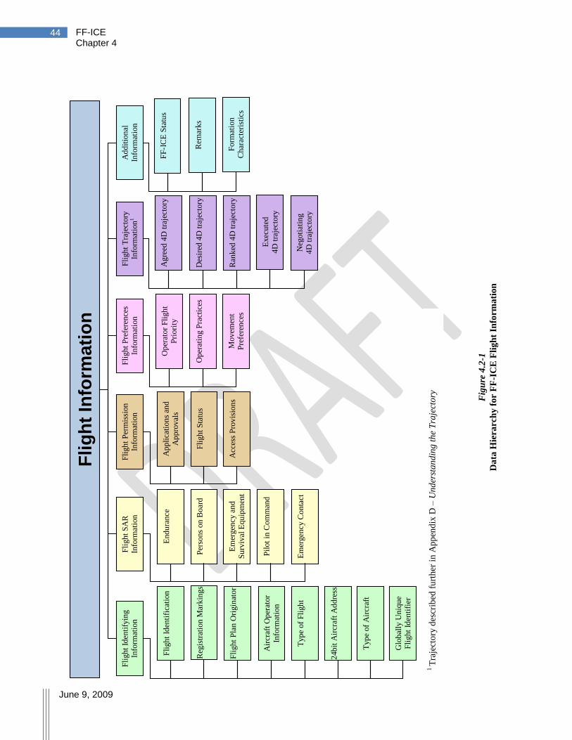
FF-ICE Chapter 4
June 9, 2009
44
Fig
ure
4.2
-1
Da
ta H
iera
rch
y f
or
FF
-IC
E F
lig
ht
Info
rma
tio
n
1
Fli
gh
t In
form
ati
on
Fli
gh
t Id
enti
fyin
g
Info
rmat
ion
Fli
gh
t S
AR
Info
rmat
ion
Fli
gh
t P
erm
issi
on
In
form
atio
n
Fli
gh
t P
refe
ren
ces
Info
rmat
ion
Fli
gh
t T
raje
ctory
In
form
atio
n1
Ad
dit
ion
al
Info
rmat
ion
Fli
gh
t Id
enti
fica
tion
Air
craf
t O
per
ator
Info
rmat
ion
Fli
gh
t P
lan O
rigin
ator
Reg
istr
atio
n M
ark
ings
Typ
e of
Fli
gh
t
24b
it A
ircr
aft
Ad
dre
ss
Typ
e of
Air
craf
t
Glo
bal
ly U
niq
ue
Fli
gh
t Id
enti
fier
End
ura
nce
Per
son
s on
Boar
d
Em
ergen
cy a
nd
Su
rviv
al E
qu
ipm
ent
Pil
ot
in C
om
man
d
Em
ergen
cy C
on
tact
Ap
pli
cati
on
s an
d
Ap
pro
val
s
Fli
gh
t S
tatu
s
Acc
ess
Pro
vis
ion
s
Op
erat
or
Fli
gh
t P
riori
ty
Op
erat
ing P
ract
ices
Movem
ent
Pre
fere
nce
s
Ag
reed
4D
tra
ject
ory
Des
ired
4D
tra
ject
ory
Ran
ked
4D
tra
ject
ory
Exec
ute
d
4D
tra
ject
ory
Neg
oti
atin
g
4D
tra
ject
ory
FF
-IC
E S
tatu
s
Rem
ark
s
1 T
raje
cto
ry d
escr
ibed
fu
rth
er i
n A
pp
end
ix D
– U
nd
erst
an
din
g t
he
Tra
ject
ory
Fo
rmat
ion
Char
acte
rist
ics

FF-ICE Chapter 4
June 9, 2009
45
4.2.2 Data Classes and Elements 1
This sub-section provides a summary of the information elements with their purpose. 2
4.2.2.1 Flight Identifying Information 3
This high-level classification groups information to help identify the flight, airframe or 4
participants. 5
Flight Identification – This field contains the ICAO designator for the aircraft operating 6
agency followed by the flight identification number or aircraft registration. This field is 7
used to identify the flight in communication with aircraft. It is used on displays such as 8
lists (including strips) and data blocks. 9
Registration Markings – Consistent with current flight information, this field contains the 10
registration markings of the aircraft. 11
24-bit Aircraft Address – This field includes the 24-bit ICAO address of the aircraft. 12
Information is used by automation to correlate communications and surveillance data 13
with flight information. 14
Aircraft Operator Information – Name and contact information of the aircraft operator. 15
Information is used for emergencies and routine administrative processes. 16
Flight Plan Originator – Name and contact information of the originator of the FPL. 17
Information is used for emergencies and routine administrative processes. 18
Type of Flight – This field identifies the type of flight; for example: scheduled air-19
transport, non-scheduled air-transport, military, unmanned aerial systems (UAS), military 20
UAS, general aviation, general aviation – charter, or general aviation – fractional. The 21
information is used for accurate identification of ATM segment use and supports ATM 22
performance evaluation. 23
Type of Aircraft – This field specifies the type of aircraft in a flight. Information is used 24
for planning and identification of resource contention such as AO. In a performance-25
based ATM System, the aircraft type will no longer be used as a surrogate for wake 26
performance. 27
Globally Unique Flight Identifier – This field specifies a globally unique reference to the 28
flight, allowing all eligible members of the ATM Community to unambiguously refer to 29
information pertaining to a flight. 30
Example- 31
The GUFI will be provided by the first ASP or a dedicated ASP to which the initial 32
flight information is provided. This service of requesting and issuing the GUFI 33
needs to be available across different SWIM Regions for long-haul flight between 34
different ICAO regions. 35
A global schema will be provided to ensure the uniqueness of the identifier. One 36
approach requires the issuance of a unique prefix to all ASPs authorized to issue a 37
GUFI. A locally unique identifier, subject to formatting constraints, would then be 38
attached to the unique prefix. 39
40
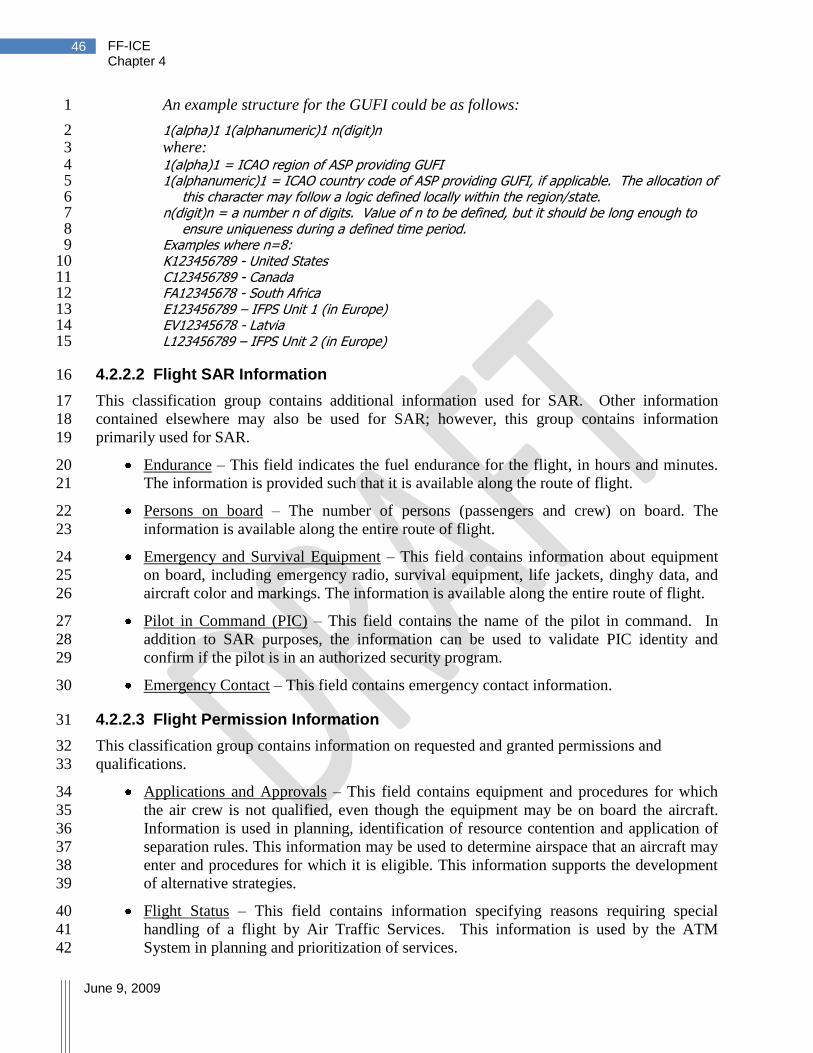
FF-ICE Chapter 4
June 9, 2009
46
An example structure for the GUFI could be as follows: 1
1(alpha)1 1(alphanumeric)1 n(digit)n 2 where: 3 1(alpha)1 = ICAO region of ASP providing GUFI 4 1(alphanumeric)1 = ICAO country code of ASP providing GUFI, if applicable. The allocation of 5
this character may follow a logic defined locally within the region/state. 6 n(digit)n = a number n of digits. Value of n to be defined, but it should be long enough to 7
ensure uniqueness during a defined time period. 8 Examples where n=8: 9 K123456789 - United States 10 C123456789 - Canada 11 FA12345678 - South Africa 12 E123456789 – IFPS Unit 1 (in Europe) 13 EV12345678 - Latvia 14 L123456789 – IFPS Unit 2 (in Europe) 15
4.2.2.2 Flight SAR Information 16
This classification group contains additional information used for SAR. Other information 17
contained elsewhere may also be used for SAR; however, this group contains information 18
primarily used for SAR. 19
Endurance – This field indicates the fuel endurance for the flight, in hours and minutes. 20
The information is provided such that it is available along the route of flight. 21
Persons on board – The number of persons (passengers and crew) on board. The 22
information is available along the entire route of flight. 23
Emergency and Survival Equipment – This field contains information about equipment 24
on board, including emergency radio, survival equipment, life jackets, dinghy data, and 25
aircraft color and markings. The information is available along the entire route of flight. 26
Pilot in Command (PIC) – This field contains the name of the pilot in command. In 27
addition to SAR purposes, the information can be used to validate PIC identity and 28
confirm if the pilot is in an authorized security program. 29
Emergency Contact – This field contains emergency contact information. 30
4.2.2.3 Flight Permission Information 31
This classification group contains information on requested and granted permissions and 32
qualifications. 33
Applications and Approvals – This field contains equipment and procedures for which 34
the air crew is not qualified, even though the equipment may be on board the aircraft. 35
Information is used in planning, identification of resource contention and application of 36
separation rules. This information may be used to determine airspace that an aircraft may 37
enter and procedures for which it is eligible. This information supports the development 38
of alternative strategies. 39
Flight Status – This field contains information specifying reasons requiring special 40
handling of a flight by Air Traffic Services. This information is used by the ATM 41
System in planning and prioritization of services. 42

FF-ICE Chapter 4
June 9, 2009
47
Access Provisions – This field contains special permissions, waivers, diplomatic 1
clearances, commercial operating authority or other permissive security information. 2
Flights requiring pre-coordination for airspace access can use this field to provide 3
compliance with requirements for seamless coordination. 4
4.2.2.4 Flight Preference Information 5
This classification group contains information on preferences expressed by the airspace user. 6
The preferences expressed in this group are applicable to the overall flight. Additional airspace 7
user preferences may best be expressed within the trajectory information. 8
Operator Flight Priority – This field provides an indication of the relative priority of a 9
flight within an operators set of flights (e.g., a fleet) for assignment of delays. 10
Operating Practices – This item includes operator procedures and other operator-specific 11
information that may impact maneuvers and clearances they may be willing to accept 12
from ATC. For example, the aircraft operator may be unwilling to perform air-to-air 13
separation, circling approaches, etc. The operator may also be unwilling or unable to 14
accept a specific runway. 15
Movement Preferences – This item contains movement preferences submitted by flight 16
planners for consideration by traffic flow automation in the event that a traffic 17
management initiative becomes necessary. Examples include: Preferring a southerly 18
course deviation if a re-route is necessary; preferring a ground–delay over a re-route for 19
a pre-departure flight; any re-route less than 120 NMI is acceptable. This item is 20
applicable in situations preventing more specific indications of preference, such as an 21
airspace user not equipped to engage in negotiation. 22
4.2.2.5 Flight Trajectory Information 23
In a trajectory-based environment, much of the information on a flight is contained within the 24
trajectory. This classification includes trajectory information and multiple trajectories described 25
below. A more detailed description of the trajectory construct can be found in appendix E. 26
Agreed 4D trajectory – This field is complex as information is expected to be expressed 27
relative to the trajectory. A 4D trajectory is expressed from gate (or stand) to gate at a 28
level of fidelity required for attaining desired performance levels. The agreed 29
4D trajectory contains the current 4D trajectory that has been negotiated and agreed to by 30
the ASP(s) and the airspace user. Additional information is incorporated into the 31
trajectory as described below. 32
o Departure Aerodrome – This field identifies the departure aerodrome that can be 33
referenced in aeronautical information. 34
o Destination Aerodrome – This field identifies the destination aerodrome that can be 35
referenced in aeronautical information. 36
o Departure Surface Segment – This segment describes the elements of the overall 37
trajectory from the departure gate up to and including the departure runway. 38
Gate or Stand – The agreed 4D trajectory incorporates the departure gate or stand 39
information with reference to aeronautical information. 40

FF-ICE Chapter 4
June 9, 2009
48
Block Time & Date – The agreed 4D trajectory incorporates the estimated 1
departure time and date as the block-time and date in the departure surface 2
segment. 3
Block Time & Date Tolerance – A tolerance on the departure time. 4
Taxi Path – The agreed 4D trajectory can include an outbound taxi-path where 5
warranted. The taxi path is expressed as a series of surface elements (expressed 6
using aeronautical information elements) with speeds and node arrival times. The 7
outbound taxi-path includes de-icing time and location and, for conventional take-8
off operations, ends with a runway consistent with the specified runway. 9
Runway – The agreed 4D trajectory includes the departure runway information to 10
be consistent with the outbound taxi path. This element references aeronautical 11
information. 12
Runway Time (Estimated takeoff time and date) – The agreed 4D trajectory 13
incorporates the estimated takeoff time and date as the time at which the taxi-path, 14
including departure roll, ends and the airborne trajectory begins. 15
Runway Time Tolerance – A tolerance on the runway time. 16
Airport Slot Information – Agreed slot time from IATA slot conference. Only 17
applies to operations at coordinated airports. 18
o Airborne Segment – The airborne segment of the trajectory describes the anticipated 19
4D path of the aircraft using data elements and resolution necessary to deliver a level 20
of fidelity commensurate with requirements for each portion of the trajectory. Since a 21
4D path is provided, the 2D route is also provided as a subset of this information. The 22
airborne segment of the trajectory is expressed as a sequence of airborne trajectory 23
elements to which the following fields are associated: 24
Change Point Type – Indicates the type of change point in accordance with current 25
specifications (e.g., ARINC 702A-3). Examples include start-of-climb, level-off, 26
top-of-descent, speed change, and RTA point. This should be extended to 27
incorporate hold/delay elements and flight within a volume of airspace. 28
To-point 4D – Describes the point to which the aircraft is flying for this element. 29
This point is expressed as a latitude, longitude, altitude, and time. 30
Constituent Route – If this portion of the trajectory is on a defined route, a 31
reference to that route can be provided using references to aeronautical information. 32
This can be used when routes are required as part of airspace constraints. 33
Performance – Indicates relevant performance values for the next element of the 34
trajectory. These values are expressed with the trajectory since the performance 35
information can vary along the trajectory. Performance is expressed using the 36
performance information construct described in section 4.2.2.5.1. 37
Reference Point – Describes the reference point using aeronautical information 38
(e.g., named point). This information represents the waypoints on the route in 39
today‘s flight planning. 40
Speed – Indicates the airspeed for the point as CAS or Mach. 41
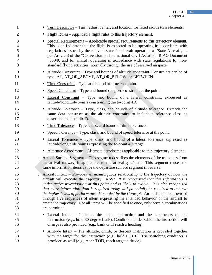
FF-ICE Chapter 4
June 9, 2009
49
Turn Descriptor – Turn radius, center, and location for fixed radius turn elements. 1
Flight Rules – Applicable flight rules to this trajectory element. 2
Special Requirements – Applicable special requirements to this trajectory element. 3
This is an indicator that the flight is expected to be operating in accordance with 4
regulations issued by the relevant state for aircraft operating as 'State Aircraft', as 5
per Article 3 of the "Convention on International Civil Aviation" ICAO Document 6
7300/9, and for aircraft operating in accordance with state regulations for non-7
standard flying activities, normally through the use of reserved airspace. 8
Altitude Constraint – Type and bounds of altitude constraint. Constraints can be of 9
type, AT, AT_OR_ABOVE, AT_OR_BELOW, or BETWEEN. 10
Time Constraint – Type and bound of time constraint. 11
Speed Constraint – Type and bound of speed constraint at the point. 12
Lateral Constraint – Type and bound of a lateral constraint, expressed as 13
latitude/longitude points constraining the to-point 4D. 14
Altitude Tolerance – Type, class, and bounds of altitude tolerance. Extends the 15
same data construct as the altitude constraint to include a tolerance class as 16
described in appendix D. 17
Time Tolerance – Type, class, and bound of time tolerance. 18
Speed Tolerance – Type, class, and bound of speed tolerance at the point. 19
Lateral Tolerance – Type, class, and bound of a lateral tolerance expressed as 20
latitude/longitude points expressing the to-point 4D range. 21
Alternate Aerodrome – Alternate aerodromes applicable to this trajectory element. 22
o Arrival Surface Segment – This segment describes the elements of the trajectory from 23
the arrival runway, if applicable, to the arrival gate/stand. This segment reuses the 24
same information items as for the departure surface segment in reverse. 25
o Aircraft Intent – Provides an unambiguous relationship to the trajectory of how the 26
aircraft will execute the trajectory. Note: It is recognized that this information is 27
under active investigation at this point and is likely to evolve. It is also recognized 28
that more information than is required today will potentially be required to achieve 29
the higher levels of performance demanded by the Concept. Aircraft intent is provided 30
through five sequences of intent expressing the intended behavior of the aircraft to 31
create the trajectory. Not all items will be specified at once, only certain combinations 32
are permitted. 33
Lateral Intent – Indicates the lateral instruction and the parameters on the 34
instruction (e.g., hold 30 degree bank). Conditions under which the instruction will 35
change is also provided (e.g., bank until reach a heading). 36
Altitude Intent – The altitude, climb, or descent instruction is provided together 37
with the target for the instruction (e.g., hold FL310). The switching condition is 38
provided as well (e.g., reach TOD, reach target altitude). 39

FF-ICE Chapter 4
June 9, 2009
50
Power Intent – The power setting and target are specified (e.g., maximum climb 1
power). The condition under which this target switches is also specified (e.g., 2
reach cruise altitude). 3
Longitudinal Intent – The along-track speed mode and target are provided. The 4
condition under which the longitudinal intent switches is provided as well. 5
Configuration Intent – The aircraft configuration and conditions under which it 6
switches are specified. 7
o Overall Performance – This field is a complex data element describing performance 8
information that applies to the entire flight. Performance attributes that vary along the 9
trajectory are described within the trajectory elements under the performance item. 10
Examples of the types of performance information include: performance on Airborne 11
Separation Assurance Systems (ASAS), merging and spacing (M&S), and station-12
keeping. 13
Desired 4D trajectory – This trajectory uses the same fields as the agreed trajectory, yet it 14
refers to the current 4D trajectory requested by the airspace user before obtaining the 15
agreed trajectory. Desired 4D Trajectories may be maintained for performance reporting 16
purposes. In a dynamic environment, the desired trajectory can change prior to departure 17
due to changing constraints (e.g., weather). Tolerances on the desired 4D trajectory 18
indicate the maximum variation around the desired trajectory before a new trajectory is 19
desired; e.g., through selection of the next-best choice in the set of ranked 4D 20
Trajectories, if available. 21
Ranked 4D Trajectories – Users wishing to express a ranked listing of preferred 22
trajectories may express a sequence of trajectories with tolerances. A set of ranked 23
trajectories would simplify or avoid negotiation with ASPs. Example: A desired 24
trajectory may be expressed with a tolerance around takeoff time. Should a departure 25
time within tolerance not be available, the next desired trajectory could be selected with 26
a different altitude and tolerance around takeoff time. 27
Executed 4D trajectory – Since the trajectory may be negotiated many times throughout 28
the flight, it is the actual trajectory executed up to the current position of the aircraft. 29
Negotiating 4D Trajectories – For trajectory negotiation purposes, multiple trajectories 30
may be required during the negotiation process. Each participant would be allowed one 31
trajectory representing their most recent proposal in the negotiation. These trajectories are 32
intended to be transitory. To keep track of negotiation, each trajectory must identify the 33
participant providing the trajectory, and a sequence number must be maintained. 34
4.2.2.5.1 Performance Information 35
This classification group contains aircraft performance information that is included within the 36
aircraft trajectory. Contained information describes the performance of the aircraft along 37
trajectory elements. 38
Wake Turbulence Performance – This field identifies the wake turbulence impact of the 39
flight as a result of the manner in which it is planned to be operated. This will be 40
specified along the trajectory, and so it allows elements for departure, en route, and 41
arrival phases of flight. This approach supports a PBA to wake turbulence separation. 42

FF-ICE Chapter 4
June 9, 2009
51
Communications Performance – This field initially identifies the equipment carried on 1
the aircraft, extends the available listing of elements and, in the final stages, identifies the 2
communications performance capability of the aircraft. Information is used in planning, 3
identification of resource contention, and application of separation rules. This 4
performance may be used to determine airspace that an aircraft may enter and procedures 5
for which it is eligible. 6
Navigation Performance – This field identifies the navigation performance capabilities of 7
the aircraft. Information is used in planning, identification of resource contention, and 8
application of separation rules. This performance may be used to determine airspace that 9
an aircraft may enter and procedures for which it is eligible. 10
Surveillance Performance – This field identifies the surveillance performance capabilities 11
of the aircraft. Information is used in planning, identification of resource contention, and 12
application of separation rules. This performance may be used to determine airspace that 13
an aircraft may enter and procedures for which it is eligible. 14
Safety Net Performance – This field identifies the safety net performance capabilities of 15
the aircraft. Information is used for awareness on the potential behavior of the aircraft. 16
Noise Performance – This field describes the environmental noise impact of the aircraft 17
as a result of the manner in which it will be operated. The inclusion of this information 18
allows the development and assignment of specific procedures based on individual 19
aircraft performance and system performance contribution. 20
Emissions Performance – This field describes the environmental emissions impact of the 21
aircraft as a result of the manner in which it will be operated. The inclusion of this 22
information allows the development and assignment of specific procedures based on 23
individual aircraft performance and system performance contribution. 24
Runway Requirement – This field describes the runway length required for an aircraft‘s 25
departure or arrival based on its weight and anticipated weather. The field informs 26
runway assignment. 27
4.2.2.6 Additional Information 28
Additional information is contained in the FF-ICE to: 29
a. Identify formation flight requirements and properties; and 30
b. Provide information to allow automation systems to communicate additional control and 31
management information. Examples include: important status information, auditing, or 32
addressing information. 33
Information items are listed below. 34
Formation Characteristics – This field provides information describing the relationship 35
requirements and properties of formation flights. Two use cases are relevant: 36
o In the case of an ICE-Formation description, this item will provide: 37
Identification of the lead aircraft; 38

FF-ICE Chapter 4
June 9, 2009
52
Horizontal/vertical bounds of the formation if non-standard (refer to 1
section 3.66); 2
Identification of each flight participating in the formation, including GUFI, 3
planed trajectory formation join point(s) and planned trajectory formation split 4
point(s); and 5
Station-keeping mechanisms. 6
o In the case of individual flights participating in formation activities, this section will 7
provide: 8
Identification of the formation lead aircraft (by Flight Identification, or 9
Formation GUFI if available); 10
Planned trajectory formation join point(s); and 11
Planned trajectory formation split point(s). 12
FF-ICE Status – This field contains status information for information management of the 13
flight information. These include the occurrence of various critical events at which the 14
provision of certain information is required. 15
Remarks – Plain language remarks as a provision for publishing non-standardized 16
information; however these remarks should not include any safety critical information all 17
of which need to be otherwise specified. 18
4.3 System-Wide Information Management 19
SWIM – integrating all relevant ATM data -- will form the technical basis for information 20
management of the entire ATM System and will be essential for its efficient operation. The 21
corresponding information management solution will be defined at the overall system level 22
rather than individually at each major subsystem and interface level. System-wide information 23
management aims at integrating the ATM network in the information sense, not just in the 24
system sense. 25
The SWIM environment will shift the ATM information architecture paradigm from point-to-26
point message exchange to system wide interoperability with associated information 27
publishing/using/contributing features. 28
SWIM is supported by a suitable architecture allowing exchange of data and ATM services 29
across the whole ATM System. The SWIM architecture aims at providing specific value added 30
information management services, the SWIM services. They will: 31
Support flexible and modular sharing of information, as opposed to closely coupled 32
interfaces; 33
Provide transparent access to ATM services likely to be geographically distributed; and 34
Facilitate the ability of applications to ensure the overall consistency of information and 35
data. 36
Specific applications will require information services subject to well-defined, potentially 37
stringent quality of service (QoS) in areas such as integrity, availability, latency, etc. In order to 38
be used to deliver services to these applications, SWIM must meet the required QoS level. There 39

FF-ICE Chapter 4
June 9, 2009
53
may be situations where QoS requirements render the SWIM environment inappropriate for 1
certain applications (e.g., a time-critical application such as air-to-air separation). 2
Not all ATM Community members will have permission to access all data within a domain 3
because of operational, commercial, or security reasons. 4
The technical systems of stakeholders participating in SWIM will have to fulfil certain 5
interoperability requirements. This capability will be provided by a set of common and standard 6
interoperability services. The range of these services available to each stakeholder will depend 7
upon stakeholder authorization. The services are: 8
Interoperability application services: a dedicated software layer to interface the ATM-9
specific sub-systems to the middleware. It offers high-level services to sub-systems that 10
either will have to publish shared data under specific conditions or will subscribe to 11
shared data updates. 12
Middleware services: a set of standard middleware services that will rely as much as 13
possible on standard, existing information technologies. 14
Standard IT services: a standard set of services for the session layer which establishes, 15
manages, and terminates connections between applications at each end; e.g., 16
authentication, permissions, and session restoration. 17
These three services belong to the Application, Presentation and Session layers respectively and 18
constitute the interoperability subsystem in the example in Figure 4.3-1. Lower layers (i.e. 19
Physical to Transport layers) will be provided through an interoperable communications network 20
infrastructure based on industry standards. 21
An example of interoperability, depicted in Figure 4.3-1, illustrates how sub-systems may 22
interact using the SWIM environment. This interaction is depicted within a region sharing a 23
uniform technical implementation and across regions with differing implementations. Within a 24
uniform implementation region, the figure illustrates the potential for operational applications 25
sharing FF-ICE information to be developed without detailed knowledge of the overall SWIM 26
network architecture. 27
For the long-term, it is expected that existing IT products deliver fully, or at least partially, the 28
middleware and application layers services. ATM specific services may have to be developed 29
and added to the IT standards in order to get the full set of required services. The description of 30
interoperability services has focused on the provision or reception of shared information, but it is 31
expected that the SWIM infrastructure will also support any point-to-point exchanges and/or 32
dialogues. The SWIM infrastructure will allow virtual point-to-point connections whereas the 33
physical network will remain the same as when the publish/subscribe pattern is used. 34

FF-ICE Chapter 4
June 9, 2009
54
Figure 4.3-1
Example of interoperability across systems, participants and SWIM technical implementations
4.3.1 Data Distribution Mechanisms 1
One paradigm of SWIM is “the migration from the one-to-one message exchange concept of the 2
past to the many-to-many information distribution model of the future, that is, many 3
geographically dispersed sources collaboratively updating the same pieces of information, with 4
many geographically dispersed destinations needing to maintain situational awareness with 5
regards to changes in that piece of information” as stated by the ICAO Global ATM Operational 6
Concept (ICAO Document 9854). 7
Figure 4.3-2 illustrates the change in information exchange implied by the above. The current 8
flight planning environment requires a collection of point-to-point message exchanges between 9
multiple individual ASPs. Since information flow is between two participants, broader 10
collaboration can be difficult. With the current system, as operational improvements have been 11
sought, individual message exchanges have been customized at both the ASP-level and 12
individual system level within the ASP. The consequence is that change can be difficult as many 13
tailored interfaces have to be modified. 14
The future of information exchange allows information to propagate system-wide and 15
accommodates the presentation of information to all parties with an interest and authorization in 16
viewing the information. With a view of common information, the collaboration process is 17
facilitated and operational constraints imposed as collaboration barriers are removed. By 18
reducing and simplifying the interfaces, the system flexibility is enhanced. 19

FF-ICE Chapter 4
June 9, 2009
55
Figure 4.3-2
Migration from point-to-point message exchange to many-to-many information distribution
Figure 4.3-2 shows the future situation as a connection of ASPs sharing information through a 1
common entity. However, it is not envisaged that SWIM will be implemented as a single, global 2
communications hub. In lieu of this approach, this functionality would be delivered through 3
multiple local providers (interacting with one or many ASPs) interoperating to provide similar 4
functionality on a global scale. 5
This Section presents features of a single SWIM Region to enable an understanding of the 6
interactions between different SWIM Regions and how interoperability may be achieved. 7
Topology – What are connectivity options for a single SWIM Region? 8
Services – What are services and how are they provided? 9
Message Exchange Patterns – How does an application obtain a service? 10
Then, briefly, the interactions between different SWIM regions and with other users with 11
present-day capabilities are described. 12
There are many technical approaches to implementing SWIM; the FF-ICE concept does not 13
prescribe a specific approach. Information would typically be distributed across multiple systems 14
and the management of a consolidated information picture is required. 15
16

FF-ICE Chapter 4
June 9, 2009
56
4.3.1.1 Topology 1
While individual approaches are expected to vary across regions, two types of architectures are 2
discussed: a centralized hub and spoke approach and a distributed enterprise service bus (ESB) 3
approach (see Figures 4.3-3 and 4.3-4). 4
Figure 4.3-3
Centralized hub and spoke architecture
In the centralized hub and spoke approach, applications rely on a centralized message broker for 5
message exchange. Applications may use an adaptor to ensure compatibility with the hub, but the 6
hub is responsible for routing messages and transforming data content. The adaptor may also 7
reside on the hub system. As the overall enterprise increases in size, a variation of this approach, 8
the federated hub and spoke, may be used to address scalability. A SWIM Region implementing 9
such an approach would find ASPs connecting SWIM-enabled systems to the SWIM Region 10
centralized hub or federated hub. 11
In the enterprise service bus approach, the applications themselves are responsible for message 12
transformation and routing. Necessary software for integration is incorporated into each 13
application. Scalability is enhanced in the ESB approach with a potential for increased 14
administrative complexity. A SWIM Region implementing such an approach would find ASPs 15
connecting SWIM-enabled systems to a SWIM Region ESB, with corresponding standards-16
compliant software on each application allowing each application to deliver its corresponding 17
services. 18
Figure 4.3-4
Distributed Enterprise Service Bus architecture
BUS
Application - 1
Adaptor
Application - 2
Adaptor
Adaptor
Application - 3
Data
Data
Data
Hub –
Centralized
message
broker
Application - 1
Application - 2
Application - 3
= Adaptor
Application - 4
Data
Data Data
Data
FF-ICE Chapter 4
June 9, 2009
57
4.3.1.2 Services 1
Invoking services is the prime means for a user to retrieve information in the SWIM 2
Environment as described in the following example: 3
A participant, connected to a SWIM Region, wishes to invoke a specific service such as 4
determining the currently estimated arrival time for a flight. The participant must first be 5
aware that this service is available and how to invoke it. This is accomplished through a 6
process of registration and discovery. The application providing the service registers the 7
service in a registry specific to the SWIM Region, including how to be invoked. The 8
participant uses a discovery service to discover the service and its invocation. The user then 9
invokes the service as described. This could involve a request/reply message exchange 10
pattern with the responsible application. Security services are used both to ensure the 11
identification of the participant and to ensure the participant is authorized to access the 12
service. The application then provides the requested information as a reply message. 13
It is expected that discovery and registration of services will be dynamic, but operational use 14
of new services will have to follow well-defined implementation procedures and will not be 15
fully automated. 16
Services can be categorized in a number of useful ways. Users and developers need to find 17
appropriate categories to deal with the various services needed in their context. Depending on 18
the complexity of the information required and its distribution within a SWIM Region, services 19
can be classified2 as follows: 20
Basic Services: 21
o Basic Data Services read or write data to or from one backend. Data should not be 22
structured as a complex database table but should consist of simple types. 23
o Basic Logic Services require some input data and produce data as output. The service 24
is at the lowest possible level, meaning no additional services are required. These will 25
require processing from a single backend. 26
Composed Services are derived from the execution of multiple basic services or other 27
composed services (see Fig. 4.3-5). These may require services from one or more back-28
ends. With the interaction of multiple back-ends, mechanisms are required to ensure 29
transactional integrity (e.g., through two-phase commits or compensation). Composed 30
services are considered stateless. 31
Process Services are longer-lived services that maintain a state. These types of services 32
will use both basic and composed services. 33
Some examples within the context of the FF-ICE are: 34
Basic services may represent requests for information on certain data items (e.g., departure time 35
for a specified flight). A composed service may be the acceptance of information governed by 36
complex acceptance rules (e.g., a proposed 4D trajectory would need to be verified against 37
constraints before being updated). A process service would need to maintain state information 38
(e.g., a multi-stage negotiation with status of acceptance). 39
2Josuttis, Nicolai M., SOA In Practice, O‘Reilly 2007

FF-ICE Chapter 4
June 9, 2009
58
Figure 4.3-5
Illustration of composed service through an Enterprise Service Bus (ESB)
The use of composed and process services presupposes the use of orchestration to achieve a 1
more complex service (as illustrated in Figure 4.3-5). This relies on the combination of more 2
elementary services where a responsible agent manages the invocation of the basic services. An 3
alternative approach involves the use of choreography whereby services are still combined, but 4
the combination is achieved through the invocation of services by each service in a workflow. A 5
choreographed approach requires rules to govern the collaboration of services to deliver higher-6
level functions. 7
In practice, a SWIM Region is likely to implement services using a combination of 8
choreographed and orchestrated approaches as there are tradeoffs for each approach (e.g., 9
scalability and complexity). 10
What the classification of services indicates is that the delivery of basic services can reside on 11
applications with direct access to the backend (e.g., retrieving a certain information item). 12
Composed and process services can be distributed on applications not specifically tied to a 13
backend. However, these do require one or more systems to implement them. These services 14
may be assigned to systems associated with an existing backend, or to standalone applications. 15
As an example, one design alternative for the FF-ICE involves an application responsible for the 16
delivery of all composed and process services associated with FF-ICE information (i.e. an FF-17
ICE information manager). This may also act as a proxy for basic services delivered through 18
other application. 19
20
BUS
Backend Backend
Basic Data
Service
Basic Logic
Service
Basic Data
Service
Basic Logic
Service
Composed
Service
1 2 3
Invokes services 1, 2, 3

FF-ICE Chapter 4
June 9, 2009
59
4.3.1.3 Message Exchange Patterns 1
Within a given SWIM Region, the provision of services will be accomplished through the 2
exchange of messages between applications. Several types of message exchanges are expected to 3
be supported within a SWIM environment including: 4
Synchronous request / reply 5
Asynchronous request / reply 6
One way (―fire-and-forget‖) 7
Publish / subscribe 8
These message exchange patterns are discussed in more detail below. This section discusses 9
message patterns for exchange of information at an application level. At lower layers different 10
patterns may be used to support fault-tolerant message exchange. 11
Figure 4.3-6 illustrates a synchronous request / reply message pattern. A consumer would request 12
a service via SWIM middleware (which could simply be a network connection). The middleware 13
routes the request to the service provider, as identified in the request. The provider then executes 14
the request and provides a reply to the middleware which is forwarded to the original consumer. 15
The synchronous nature of the message pattern indicates that the consumer waits for a reply 16
before continuing any other processing. Since the consumer is blocked from performing any 17
other functions, this pattern is only applicable to services that can execute quickly. 18
Figure 4.3-6
Synchronous request/reply message pattern
The asynchronous request / reply message pattern differs from the synchronous message pattern 19
by the feature that the consumer is not blocked from using other services while waiting for a 20
response. This is more suitable to interactions when the response time can be longer. However, 21
the complexity is significantly increased as the consumer must be able to receive messages at 22
any time and must be able to correctly associate replies with prior requests regardless of timing. 23
MiddlewareConsumer Provider
Request
Request
Execute Request
ReplyReply
sd Interaction10

FF-ICE Chapter 4
June 9, 2009
60
Figure 4.3-7
Asynchronous request/reply message pattern
The one-way message pattern, also referred to as a ―fire-and-forget‖ pattern, involves the 1
consumer of the service sending a message to the service provider without expectation of a reply. 2
This pattern may be at an application level while message assurance requirements will involve a 3
higher level of interaction at the protocol level. 4
The publish/subscribe message pattern involves two interactions: subscription and publication. 5
Each of these interactions may be implemented using either of the design patterns described 6
above. A request/reply pattern is used at application level to ensure that a subscription has been 7
successful. In its most general sense, a subscription lets the service provider know that the 8
consumer is interested in receiving notification of an event. With regards to the FF-ICE, a 9
subscriber wishes to know when information has been changed. This may result in either the 10
publication of the information or notification that the information has been changed. In the latter 11
case, a separate service is required to obtain the information. 12
With the publish/subscribe pattern, subscription can be arranged with filters at different levels of 13
granularity. This refers to how finely one can request notification that information has changed 14
(e.g., notify when a trajectory has changed, versus notify when a specific item has changed). 15
4.3.1.4 Interacting SWIM Regions 16
The prior sections identified certain expected properties of a SWIM Region. When multiple 17
SWIM Regions interact with differing technical implementations, the systems should 18
interoperate to deliver a combined capability aligned with the information management vision in 19
the Global ATM Operational Concept. 20
Interoperability between SWIM Regions is expected to be provided through adaptors at each 21
SWIM Region interface. For SWIM Regions implementing identical technical solutions, the role 22
of these adaptors could simply be the provision of connectivity. SWIM Regions implementing 23
differing communications protocols or messaging will require translation at the appropriate 24
layers. Further differences between regions introduce additional functional requirements for the 25
SWIM Region adaptors. In general, the purpose of the adaptor is to represent the data interests of 26
participants in one SWIM Region to the participants of another. 27
Differences in architectural choices between SWIM Regions such as hub-and-spoke versus 28
enterprise service bus imply differences for the adaptors integrating these regions. In a hub-and-29
spoke architecture, the adaptor functionality can be integrated into the hub system. For the bus-30
MiddlewareConsumer Provider
Non-blocking
Request
Request
Execute Request
Reply
Reply
sd Interaction11
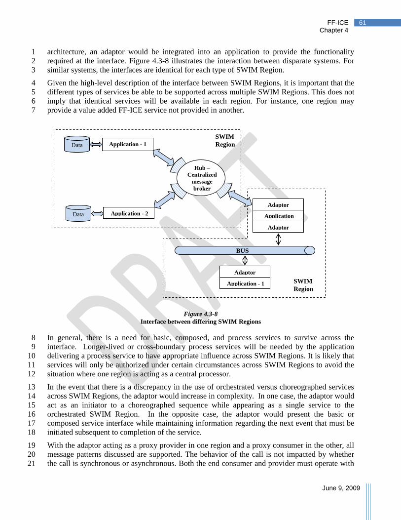
FF-ICE Chapter 4
June 9, 2009
61
architecture, an adaptor would be integrated into an application to provide the functionality 1
required at the interface. Figure 4.3-8 illustrates the interaction between disparate systems. For 2
similar systems, the interfaces are identical for each type of SWIM Region. 3
Given the high-level description of the interface between SWIM Regions, it is important that the 4
different types of services be able to be supported across multiple SWIM Regions. This does not 5
imply that identical services will be available in each region. For instance, one region may 6
provide a value added FF-ICE service not provided in another. 7
Figure 4.3-8
Interface between differing SWIM Regions
In general, there is a need for basic, composed, and process services to survive across the 8
interface. Longer-lived or cross-boundary process services will be needed by the application 9
delivering a process service to have appropriate influence across SWIM Regions. It is likely that 10
services will only be authorized under certain circumstances across SWIM Regions to avoid the 11
situation where one region is acting as a central processor. 12
In the event that there is a discrepancy in the use of orchestrated versus choreographed services 13
across SWIM Regions, the adaptor would increase in complexity. In one case, the adaptor would 14
act as an initiator to a choreographed sequence while appearing as a single service to the 15
orchestrated SWIM Region. In the opposite case, the adaptor would present the basic or 16
composed service interface while maintaining information regarding the next event that must be 17
initiated subsequent to completion of the service. 18
With the adaptor acting as a proxy provider in one region and a proxy consumer in the other, all 19
message patterns discussed are supported. The behavior of the call is not impacted by whether 20
the call is synchronous or asynchronous. Both the end consumer and provider must operate with 21
BUS
Hub –
Centralized
message
broker
Application - 1
Application - 2
Data
Data
Application
Adaptor
Adaptor
Application - 1
Adaptor
SWIM
Region
SWIM
Region

FF-ICE Chapter 4
June 9, 2009
62
a shared understanding regarding the type of message pattern being used. Having the adaptor 1
introduce or destroy a message is not acceptable. The adaptor must be capable of associating the 2
reply to the correct consumer for addressing purposes. 3
Subscription and publication, being delivered through a sequence of simpler exchange patterns 4
can also be offered across the SWIM Regions. However, since the adaptor acts as both the 5
subscriber and publisher, the adaptor must be capable of determining to whom a publication is 6
provided. 7
In the event of multiple consumers requesting the same subscription, it may be desirable for the 8
adaptor to request a single subscription which, upon publication, is distributed by the adaptor. 9
This may only be accomplished for those subscriptions that do not require end-to-end 10
authorization. 11
Discrepancies in the level of granularity of allowable subscriptions can be dealt with at the 12
consumer or adaptor level. It is strongly recommended that the level of granularity be 13
harmonized across interfaces to reduce development and processing costs. 14
For services to survive the interface between differing SWIM Regions, the adaptor will have to 15
manage complex interactions depending on several factors such as the types of services 16
provided, the message patterns in use, and granularity of subscription information. 17
4.3.1.5 Interaction with Non-SWIM Participants 18
In addition to having SWIM Regions interacting, there may be additional participants interacting 19
with a SWIM Region. These include airspace user systems with present-day filing capabilities or 20
ASPs not yet providing SWIM services. When an interface to a specific SWIM Region is 21
required, an adaptor would be provided to ensure that capabilities are provided, through 22
translation, to SWIM services and back. An ASP without SWIM may implement the FF-ICE 23
concept using alternative system architectures, and with a system responsible for managing FF-24
ICE information (Figure 4.3-9). 25
Figure 4.3-9
Connectivity for non-SWIM Participants
Additional discussion on the subject of interactions with present-day capabilities is provided in 26
Chapter 5, Transition. 27
FF-ICE
Management
SWIM Region
Adaptor
Custom messages
FF-ICE Services

FF-ICE Chapter 4
June 9, 2009
63
The flight deck presents unique requirements in the FF-ICE concept. (It is recognized that certain 1
operations, such as UAS, will not be subject to these same requirements.) The global nature of 2
airframes and their avionics favors a system with consistent global interfaces and flight deck 3
procedures. The FF-ICE concept indicates that information will both be provided and retrieved 4
from a SWIM Region. There are many options for providing this functionality. Air/ground data 5
communication can provide connectivity, but the specific level of integration has not been agreed 6
upon. Two examples of integration include: 7
Connectivity to a SWIM Region can be provided through data communications with a 8
ground system connected to the SWIM Region bus or hub; 9
Connectivity to a SWIM Region can be provided through data communications with a 10
ground system operating with a human-in-the-loop (ATC or flight operations 11
centers [FOC]) providing acceptance of content in both directions. 12
The specific services provided to the flight deck will likely be limited to a subset of services 13
offered. In addition, the flight deck would be mostly a consumer of services, and provide strict 14
authorization limits on services provided by the flight deck. Management of data services to the 15
flight deck can be accomplished as part of ground systems providing data communications 16
connectivity. This includes accomplishing seamless transfer of control functions as a flight 17
migrates from one SWIM Region to another. 18
Some airspace users will have access to FOCs which are expected to be connected to one or 19
more SWIM or non-SWIM Regions. For airspace users without access to a FOC, several POE 20
options may be available. 21
The FF-ICE equivalent of flight planning services will provide connectivity in much the 22
same manner as the FOC. Some level of certification and authorization is expected of all 23
entities providing connectivity. 24
Some ASPs may also elect to provide a service (e.g., through the internet) allowing 25
airspace users to provide FF-ICE information. The interaction could continue over 26
multiple sessions. This system would provide a front-end for connectivity. 27
4.4 Infrastructure 28
The infrastructure of the FF-ICE needs to provide interoperability mechanisms at a lower level 29
than the FF-ICE application. This includes also infrastructure services for: 30
Security – Security services must be provided to ensure such aspects as identification, 31
authentication, authorization, integrity, and confidentiality. 32
Reliability – The infrastructure must ensure a known level of reliability. For instance, 33
delivery of messages should be assured with specification on delays and multiple deliveries. 34
Auditing – The infrastructure should support logging information flows to support 35
troubleshooting and to enable issuance of responsibility for user-initiated faults. 36
Service Management – Delivery of services requires the ability to maintain and provide 37
information regarding the services themselves. This can include service registration, 38
discovery, and version control. Version control may include translation services to ensure 39
backward compatibility. 40
FF-ICE Chapter 4
June 9, 2009
64
In addition, the infrastructure needs to achieve physical connectivity between all stakeholders 1
and to assure data consistency at the lower layers of the information hierarchy. 2
In the following sections, the infrastructure is presented in terms of 3
Communication Network 4
Safety and Security Features 5
Data Exchange Formats 6
4.4.1 Communication Network 7
Ground-ground communication enables the information flows between FF-ICE stakeholders; 8
e.g., ATC units, airspace users, Airport Operators and other affected or interested parties, on the 9
national, sub-regional or regional level. With the FF-ICE concept, data volumes and the level of 10
automation will continue to increase to support the higher levels of co-ordination and 11
collaboration in the future operational environment, where ATC, AOC and airport systems are 12
inter-connected. 13
There is a need for a standard ATM network to support the services described. ICAO is looking 14
into IPv6 network as a possible approach. 15
4.4.1.1 Dissemination of Information 16
In a SWIM Region, a process of rules, registration and discovery will be used. Rules refer to the 17
operational knowledge of which ASP should be provide this information. For example, one 18
SWIM Region covering multiple ASPs may have a centralized service, whereas another SWIM 19
Region may require filing with the individual departure ASP within the region. Registration and 20
discovery provides knowledge of format and addressing information for provision of initial 21
FF-ICE information within that region. Since these requirements are expected to be relatively 22
static, it is not anticipated that these would lead to the provision of ―run-time‖ registration and 23
discovery. 24
In a non-SWIM Region, the process is similar, yet rules also specify addressing and formatting 25
requirements (e.g., in an Interface Control Document). 26
The provision of information to all interested ASPs would occur through a similar process of 27
rules, subscription and publication. When the initiating ASP receives initial flight information, 28
the following mechanisms would indicate how the information is propagated: 29
Previously agreed upon rules indicate that flights with specific properties should result in 30
FF-ICE information being provided pertaining to the flight. These properties include 31
flight through specific airspace, including areas of interest to an ASP. 32
For ASPs with publish/subscribe capabilities, the receiving ASP has subscribed to the 33
flight information with filtering criteria on the flight similar to the properties above. 34
It is imperative that rules be vetted for consistency across regions. For example, a region 35
interested in receiving flight information 6 months before entry is not consistent with a region 36
providing flight information only 24 hours before departure. 37

FF-ICE Chapter 4
June 9, 2009
65
4.4.1.2 Transfer of Control 1
As a flight operates with control transferring between ASPs, it is expected that services offered 2
on the FF-ICE information will change. This change can be due to transferring responsibility 3
from one ASP to another (i.e., only one ASP can be responsible for certain data items) or due to 4
a change in the level of service offerings between ASPs (i.e., one ASP offers more services than 5
another). Transferring control may trigger a change in the authorization for certain services 6
offered within each ASP. One SWIM Region may provide process services that maintain the 7
state of a flight‘s control and use the appropriate basic or composed services provided by the 8
controlling entity. 9
Transferring control into a non-SWIM Region similarly results in transferring message 10
authorization. Authorized services provided by SWIM Regions can continue to the extent that 11
the interface provides access to the information required. 12
4.4.2 Safety and Security Features 13
4.4.2.1 Safety 14
The future ATM System architecture will be distributed instead of being an aggregation of local 15
systems like today‘s ATM System. Air and ground systems will be considered as one inter-16
connected system. 17
More automation will be required in order to accommodate both the increase in traffic and the 18
future safety and environmental requirements. The key systems and sub-systems associated with 19
the FF-ICE concept have been recognized as the ones that should meet the highest expectations 20
in terms of availability, continuity, and integrity as they may have an impact on the safety 21
performance of the future ATM System. 22
As a result, hardware and software solutions should be implemented to meet the required level of 23
safety. This would include: 24
Fault tolerance mechanisms 25
Redundancy, 26
Diversity of code 27
Fallback systems 28
Contingency procedures 29
As an example, necessary fault tolerance features are discussed. 30
Message assurance will likely exist at multiple layers in the communications stack. It is expected 31
that messaging will occur over a communications infrastructure with the assurance that messages 32
will arrive at their destination with known levels of performance. Even with this level of message 33
assurance, network failures occur, there can be application-level errors, longer than expected 34
delays may occur, and the recipient of a message may not be available at the time a message is to 35
be received. 36
Many applications will require application-level message assurance. This level not only protects 37
against network reliability issues, but informs applications that messages have been successfully 38
received and understood by the receiving system. One robust method for ensuring that a message 39

FF-ICE Chapter 4
June 9, 2009
66
has been delivered and understood includes a double acknowledgement. This approach ensures 1
the service provider is aware that the confirmation was received. 2
Interactions can sometimes result in errors which can trigger a fault message rather than an 3
expected reply. Messages for these application-level errors need to be described and specific 4
rules governing conduct subsequently must be defined. 5
For certain request/reply interactions, a longer than expected delay can occur before receiving a 6
reply. This can prompt the sending application to try again. This situation may lead to anywhere 7
from zero to two responses in any order. The sending application must be prepared to deal with 8
the consequences of any combination of responses (e.g., out-of-order, no response, response not 9
associated with the last message sent). This includes both the technical acceptance of the 10
messages and how to incorporate the information. The application providing the service must be 11
capable of receiving multiple identical requests without detrimental consequences. 12
When systems are unavailable for brief or extended periods of time, what happens to messages 13
destined for the unavailable system will depend on the properties of the middleware (i.e., the hub 14
or bus described under Section 4.3.1.1, Topology). Certain middleware, such as message-15
oriented middleware, will incorporate messaging queues into the middleware to ensure message 16
persistence when the destination is unavailable. 17
4.4.2.2 Security 18
The FF-ICE concept is an important milestone on the migration of the ATM System towards the 19
future performance-based system. Therefore, security impacts must be considered during 20
development of its technical environment. 21
The current infrastructure of data formats, protocols, and distribution mechanisms for flight data 22
exchange provides little in the way of information security. One outcome of this lack of 23
information protection is the limited provision and availability of certain confidential 24
information that could help airspace users and ATM providers work collaboratively to improve 25
the level of service while satisfying user preferences and meeting ATC resource constraints. 26
The security of the information will have to be managed commensurate with the potential 27
increased access to the infrastructure. Security of SWIM-based information networks will need 28
to be harmonized with the on-board networks of connected aircraft and the data links. 29
To fully protect the information during its lifetime, each component of the information 30
processing system must have its own protection mechanisms by building up, layering on, and 31
overlapping of security measures through a so-called defence-in-depth mechanism. The main 32
layers of intervention are at network and data level. 33
The first level of security from cyber attacks is established by securing the network infrastructure 34
used to transport the information. 35
System wide security management functions (e.g., access control, network management) will be 36
integrated and will meet the broadly accepted information system security needs: 37
Identification: The recipient of information needs to determine the identity of the sender. 38
Information received may be a request for services or information related to the FPL. 39
Authentication: The recipient of information must ensure that the identity of the sender is 40
valid. 41

FF-ICE Chapter 4
June 9, 2009
67
Authorization: The recipient must determine the level of access granted to an authenticated 1
second party. This access is for providing or receiving data or services. 2
Integrity: Transmitted data must remain unaltered until final delivery. 3
Confidentiality: Transmitted data must not be viewed by unauthorized entities. 4
Availability: While not exclusively a security concern, the introduction of ―denial of 5
service‖ attacks makes some aspects of availability a security issue. Availability ensures that 6
FPL information and services can be accessed when required. The security component deals 7
with availability as a result of deliberate actions (versus system malfunction) to deny 8
availability. 9
Accountability: Authorities must be able to determine the actions of the interacting agents 10
and to identify the agents. Audit trails support accountability. 11
4.4.3 Common Data Formats 12
The FF-ICE will use the XML (XML) as the basis for describing data formats. XML is a W3C 13
recommended general-purpose mark-up language. It provides a set of rules for defining and 14
conveying structured data. Almost any kind of data can be defined with XML, and applications 15
can modify and validate XML based data since it is in a self-documenting format which 16
describes the structure as well as the values. 17
XML is not new to ATM and is currently being used in a program called AIXM which enables 18
the exchange of aeronautical information as XML encoded data. 19
4.4.3.1 Use of XML in FF-ICE Environment 20
The FF-ICE will be based upon global information standards defining a core set of valid data 21
elements with regional requirements on their use. Regional extensions on data elements are 22
permitted in accordance with harmonized global practices for defining and referring to these 23
elements. 24
The global information standard for the FF-ICE will be defined through published XML schemas 25
under version control and maintained by ICAO. If operationally needed and viable, regional 26
extensions to or implementations of the information standard may be considered. These regional 27
extensions would then be published as regional XML schemas with version control. As 28
information is provided, use of different namespaces can allow valid schemas from multiple 29
regions to be unambiguously referred to in a single XML message. 30
XML schema can be used to validate an XML message to ensure compliance with the defined 31
standard. In this manner, providers of information can also ensure compliance with the standard. 32
The specification of an XML schema description requires the structuring of the FF-ICE 33
information items. An example structure is provided in Appendix G as a proposed class 34
hierarchy for the top level flight information items. The resulting XML schema definition (XSD) 35
represents the specification that would be used to validate information that is provided for the 36
FF-ICE. 37
38

FF-ICE Chapter 4
June 9, 2009
68
With the use of XML in the FF-ICE environment, several benefits would be available: 1
The strict syntax and parsing requirements allow the necessary parsing algorithms to 2
remain simple, efficient, and consistent. 3
XML extensibility allows flexibility for the future and allows individual regions to 4
implement local extensions for local performance needs. 5
Support for format validation through XSDs and document type definitions (DTDs). 6
Versioning to facilitate the evolution of information content. 7
Backward compatibility during transition 8
XML encryption supports end-to-end security for secure exchange of structured data 9

FF-ICE Chapter 5
June 9, 2009
69
5 Transition
The FF-ICE is being developed to support the migration towards the future Global ATM 1
Operational Concept as envisaged in ICAO Document 9854. While significant benefits are 2
anticipated, the transition from the current flight planning system to a future FF-ICE will involve 3
operational impact on the processes and systems of all participants involved in the creation, 4
dissemination and processing of FF-ICE information. 5
The fulfillment of ATS operational requirements for FPL data reception, processing, display and 6
distribution is a pre-requisite for the present Flight Plan and the transition to the FF-ICE. This 7
chapter describes several key operational transition areas affected by future flight information, 8
and describes possible methods for mitigating any important transition issues. 9
5.1 Characteristics of Transition 10
Transition to the FF-ICE is expected to possess the following characteristics: 11
The FF-ICE will replace the present FPL as the single, global standardized message 12
exchange process for FPL information. 13
Not every participant in the ATM System will transition to the FF-ICE simultaneously 14
although certain states and regions may be able to act cooperatively to make the transition 15
together. 16
The flight planning capability of service providers, including regional FPL/information 17
processing capabilities, will be known to all members of the ATM Community. 18
The transition phase must be developed with due consideration to the transient 19
performance impact on aircraft operators and ASPs. 20
Adjacent regions may operate with different types of FPLs (i.e. future versus present). 21
Flights operating across these boundaries require the ability to provide flight information 22
to both types of regions and a mechanism must be defined for in-flight amendments 23
across differing regions. 24
With the new FF-ICE mechanisms in place, additional procedures or services associated 25
with this information will become available. These are expected to provide 26
enhancements that encourage early adoption of the FF-ICE. 27
Participants may have to accommodate both the present Flight Plan and the FF-ICE for 28
some period during the transition phase. 29
There must be no reduction in safety during the transition period. 30
Furthermore, it is unlikely that the FF-ICE will be implemented as a ‗big-bang‘ in any region. It 31
is more likely that each individual region may decide to follow a stepwise implementation by 32
which the major characteristics of the FF-ICE will gradually be implemented over a number of 33
years, eventually leading to a full implementation. 34
During transition, a situation will have to be considered in which different regions are 35
transitioning at different speeds, while maintaining operational service and making the best use 36
of the FF-ICE aspects which they have implemented at each step. 37
FF-ICE Chapter 5
June 9, 2009
70
Benefits from transition are likely to be optimized if each region follows a compatible 1
evolutionary plan. 2
5.2 Flight Data Extraction and Processing 3
In the FF-ICE not only is the information that is being provided through the FPL changed, but 4
the flight information process is made more long-lived, with a dynamic and collaborative process 5
between various agents in the ATM System. These changes will require similar updates to the 6
infrastructure as for formats and protocols, but for different purposes: 7
Operator flight planning systems – the collaborative process will allow aircraft operators 8
to interact with existing shared flight information, operators wishing to take advantage of 9
this will require an ability to extract and process this information. 10
ASP and Aerodrome systems – changes to the flight information process, including 11
earlier, different and more frequently updated information will require changes in the 12
processing of this information. Additional capabilities enabled through these changes 13
will require modifications to implementing systems. Interfaces and interactions between 14
systems may also require modifications to implement the new flight information process. 15
Documentation and training – Changes to procedures and systems necessitate new 16
documentation and training to implement these changes. 17
5.3 Information Access Requirements 18
The FF-ICE will consider requirements of member states regarding the need for information. 19
Some of this information will have its access limited, and security measures will be in place to 20
ensure that this access is strictly controlled. Additional security measures will likely be 21
implemented for information confidentiality and integrity. This represents a change from the 22
present Flight Plan which has limited control mechanisms for security. These measures will 23
impose requirements on the infrastructure (networks and interacting systems) through which the 24
future Flight Plan will be transported. It is unlikely that, during transition, present-day systems 25
will be able to support these capabilities. 26
5.4 Impact on Other ATS Messages 27
Changes to the flight information provision process will result in required changes to additional 28
ATS Service messages. In particular, all messages which rely on data fields defined for the FPL 29
will be impacted by changes to the data fields. 30
The multiple phases of the FF-ICE are expected to alter or remove the need for the various filed 31
FPL update messages depending on implementation. The more dynamic and collaborative 32
nature of flight information will require earlier information provision and more frequent updates 33
with unambiguous reference to existing flight information. 34
Coordination messages will be impacted by changes to the information format, exchange 35
mechanisms, and the flight information process. The Global ATM Operational Concept and 36
associated requirements indicate the need for shared common information. The process by 37
which this information is shared will replace the current coordination messages. 38

FF-ICE Chapter 5
June 9, 2009
71
A more collaborative flight information process will allow operators to request updates to 1
downstream portions of their cleared FPL. Updating will require an ability of operators to 2
propose alternatives. 3
5.5 User Interactions 4
During transition, global operators will likely interface with both present-day and future systems 5
simultaneously. This can result in additional complexity for these operations. However, through 6
appropriate regional implementation, the number of operations affected can be kept to a 7
manageable number. 8
The introduction of the FF-ICE will allow the provision of airspace user constraints, preferences, 9
priorities and other potentially proprietary information. Through information security in the 10
FF-ICE, this information can be protected. During transition, security concerning the means of 11
information transfer between incompatible regions should be a consideration. 12
The more dynamic nature of the FF-ICE, including the provision of additional information while 13
in-flight, will require airspace users be capable of providing any additional information that has 14
been declared to be mandatory by flight information regions with future flight information 15
capabilities, even though the original filing was accomplished through present-day systems. The 16
information may be provided from the airspace user or via an authorized third party provider. 17
5.6 Actual Transition Phase 18
It is not expected that the transition to the FF-ICE will occur on a global scale all at once, and for 19
this reason, operational compatibility between existing and future flight information is required. 20
During this transition phase, processes must be in place to ensure that information required for 21
either the present Flight Plan or the new FF-ICE be provided to those ASPs using the applicable 22
approach. With regards to differences in protocols and exchange mechanisms, a compatible 23
interface gateway would likely be required during transition. 24
Flights operating between regions where the present Flight Plan is used and regions using the 25
FF-ICE will require that necessary information be passed through or around incompatible 26
regions for transmission to the next. There are a variety of alternatives for dealing with this 27
information flow, including bypassing incompatible regions. 28
A phased introduction towards the FF-ICE will have regions agreeing to local implementation 29
schedules. Furthermore, changes in the information, protocols and exchange mechanisms will 30
likely precede the associated operational and procedural changes. Upon introduction of 31
operational and procedural changes in flight information provision, changes focusing first on 32
operations exclusively within a region compatible with the FF-ICE will facilitate transition. 33
Procedures will need to consider flights operating between regions operating with both the 34
present Flight Plan and the FF-ICE. 35

FF-ICE Chapter 5
June 9, 2009
72
5.6.1 Transition Steps 1
From a user perspective, the main characteristics of the FF-ICE can be summarized as: 2
Globally Unique Flight Identifier (GUFI) 3
Provision of early flight information submissions by airspace users 4
Provision and exchange of full FF-ICE information including 4D trajectory 5
Submission, retrieval. and dissemination of the FF-ICE information 6
When all of these features have been implemented in a certain region according to the defined 7
specifications, then that region can be said to have implemented the FF-ICE concept. Appendix 8
B, Operational Transitions, elaborates possibilities for the above steps in more detail. 9

FF-ICE Appendix A
June 9, 2009
73
Appendix A. FF-ICE Information Elements
This appendix describes the information elements within the Flight and Flow Information for a 1
Collaborative Environment (FF-ICE) in support of the Global ATM Operational Concept. The 2
FF-ICE adopts a trajectory-based description of the flight information. This description is 3
explored in more detail in Appendix D, Understanding the Trajectory. The FF-ICE will also use 4
common data types to describe information. It is expected that these types will be harmonized 5
within the broader ICE environment. For example, a ―runway‖ type or ―taxi-path‖ type would 6
be consistent between the FF-ICE and aeronautical information descriptions. 7
The information elements are first compared to the items in the present-day Flight Plan to ensure 8
that existing information is preserved, or justification is provided to remove it. 9
A.1 Information Element Mapping 10
Table A-1 describes the migration of the current flight plan information items into elements 11
contained in the FF-ICE. 12
A.2 Information Element Description 13
Information elements are organized at the highest level, as described in Figure A-1. Not all 14
information elements are included in the figure as they may be included within one of the 15
trajectories. 16
Tables A-2.1 through A-2.6.5 describe the information elements. The tables include: 17
Field name – The name of the information element 18
Field narrative description – A description of the content 19
Is it required? – Whether the item is mandatory in all cases, mandatory in some cases, or 20
strictly optional. This will provide guidance as to which items are required in the 21
development of an XML schema Definition (XSD). 22
Operational Constraints – Where known, a constraint on the formatting of the data item. 23
Definitions guide the specification of the XSD. 24
Comments – Additional information, explanation on the item, or open issues 25
Requirements – A reference to a requirement (per ICAO Document 9882) identifier 26
justifying the need for the information element 27
28

FF-ICE Appendix B
June 9, 2009
74
Table A-1
Mapping of existing FPL to FF-ICE
FP
L Ite
m
Exi
stin
g F
PL
Dat
a
Flig
ht Id
entif
icat
ion
Reg
istr
atio
n M
arki
ngs
Airc
raft
Ope
rato
r
Typ
e of
Flig
ht
For
mat
ion
Cha
ract
eris
tics
Typ
e of
Airc
raft
24-b
it A
ircra
ft A
ddre
ss
Per
f.-ba
sed
wak
e (a
rr/d
ep)
Per
f.-ba
sed
wak
e (c
ruis
e)
Per
f.-ba
sed
Com
mun
icat
ions
Per
f.-ba
sed
Nav
igat
ion
Per
f-ba
sed
Sur
veill
ance
Flig
ht S
tatu
s
End
uran
ce
Per
sons
on
Boa
rd
Em
erge
ncy
& s
urvi
val E
quip
men
t
Pilo
t in
Com
man
d
Flig
ht R
ules
Dep
artu
re A
erod
rom
e
Des
tinat
ion
Aer
odro
me
Alte
rnat
e A
erod
rom
e
Incl
uded
in a
gree
d 4D
traj
ecto
ry
Ove
rall
Per
form
ance
Rem
arks
7 Aircraft Identification x
7 Registration Marking x
8 Flight Rules x
8 Type of Flight x
9 Number of Aircraft x
9 Type of Aircraft x
9 Wake turbulence Category x x
10 Radio Comm, Nav and approach aid equipment
x x
10 Surveillance Equipment x
13 Departure Aerodrome x
13 Departure Time x
15 Cruising Level x
15 Cruising Speed x
15 Route x
16 Alternate Aerodrome x
16 Destination Aerodrome x
16 Elapsed Time x
18 CODE/ x
18 COM/ x
18 DAT/ x
18 DEP/ x
18 DEST/ x
18 EET/ x
18 NAV/ x
18 OPR/ x
18 PER/ x
18 RALT/ x
18 RIF/ x
18 RMK/ x
18 SEL/ x
18 STS/ x
18 TYP/ x
19 C/ x
19 E/ x
19 P/ x
19 R/S/J/D/N/A/ x

FF-ICE Appendix A
June 9, 2009
75
Req
s.
7,
11
13
1,
16
2
7,
11
13
1,
16
2
7
Co
mm
ents
Nee
d n
ot
be
sam
e in
form
atio
n a
s p
ilo
t in
co
mm
and
.
Th
ere
may
be
cro
ss i
ssu
es w
ith
dat
a fi
eld
len
gth
all
oca
ted
in
th
e
Mo
de
S a
ddre
ssin
g s
chem
e fo
r th
e ca
llsi
gn
/fli
gh
t ID
.
Iden
tifi
es t
he
flig
ht
on f
ligh
t st
rips,
dis
pla
y l
ists
, d
ata
blo
ck. U
sed
in c
om
mu
nic
atio
n w
ith
air
craf
t.
Hu
man
Fac
tors
con
sid
erat
ion
s: W
ork
ing m
emo
ry c
apac
ity
has
bee
n u
niv
ersa
lly f
ou
nd
to
be
7 +
/- (
2)
elem
ents
. (
An
ele
men
t, i
n
thes
e te
rms,
wo
uld
be
a d
igit
; in
nam
ing
, it
is
each
nam
ed
way
po
int;
in
lat
-lo
ng
it
wou
ld b
e ea
ch n
um
ber
or
if t
he
nu
mb
ers
cou
ld b
e le
arn
ed i
n ―
chu
nk
s‖ t
hen
it
wou
ld b
e ea
ch l
at/l
ong
p
air
(Mil
ler
19
56
, B
add
eley
199
0,
Wic
ken
s, 1
992
)) [
Cou
rtes
y
SJS
U/C
ork
er.
Mai
nta
in f
lex
ibil
ity
to
acc
om
mo
dat
e te
n c
har
acte
rs a
t a
late
r d
ate,
assu
min
g a
via
tio
n g
row
th w
ill
req
uir
e ev
entu
al e
xte
nsi
on
of
op
erat
or
IDs
to 4
ch
arac
ters
(o
ne
chu
nk
) plu
s ad
dit
ion
al 6
char
acte
rs e
qu
als
max
imu
m o
f 10 c
har
acte
rs f
or
the
fiel
d.]
Nee
d t
o i
den
tify
if
ther
e is
a s
et g
lob
al s
tand
ard
or
an e
xis
ting
max
imu
m t
o v
alid
ate
a si
ze c
on
stra
int
of
8 c
har
acte
rs.
Op
era
tio
na
l C
on
stra
ints
(Co
nte
nt
Des
crip
tio
n
6 c
har
acte
rs-
alp
han
um
eric
, ex
pre
ssed
as h
exad
ecim
al
May
no
t ex
ceed
8
char
acte
rs (
bu
t sy
stem
sho
uld
be
flex
ible
eno
ug
h
to a
cco
mm
od
ate
futu
re
gro
wth
to 1
0)
Is i
t
Req
uir
ed?
Fie
ld N
arr
ati
ve
Des
crip
tio
n
Th
is f
ield
in
clu
des
th
e 24
-bit
IC
AO
add
ress
of
the
airc
raft
.
Cu
rren
tly
OP
R/
Nam
e an
d c
on
tact
in
form
atio
n o
f th
e
airc
raft
op
erat
or.
Ph
on
e nu
mb
er,
fax,
emai
l ad
dre
ss
sho
uld
als
o b
e p
oss
ible
to
en
ter
ICA
O d
esig
nat
or
for
the
airc
raft
op
erat
ing
ag
ency
foll
ow
ed b
y t
he
flig
ht
iden
tifi
cati
on
nu
mb
er o
r
airc
raft
reg
istr
atio
n
Nam
e an
d c
on
tact
in
form
atio
n o
f th
e
ori
gin
ato
r o
f fl
igh
t pla
n
Th
is f
ield
sp
ecif
ies
a g
lob
ally
un
iqu
e
refe
ren
ce t
o t
he
flig
ht,
all
ow
ing a
ll
elig
ible
mem
ber
s o
f th
e A
TM
Co
mm
un
ity
to
un
amb
igu
ou
sly
ref
er
to i
nfo
rmat
ion
per
tain
ing
to
a f
ligh
t.
Th
e re
gis
trat
ion
mar
kin
gs
of
the
airc
raft
(co
nsi
sten
t w
ith
cu
rren
t
flig
ht
info
rmat
ion
).
Fie
ld N
am
e
24
-bit
Air
craf
t
Ad
dre
ss
Air
craf
t O
per
ato
r
Info
rmat
ion
Fli
gh
t
Iden
tifi
cati
on
Fli
gh
t P
lan
Ori
gin
ato
r
Glo
bal
ly U
niq
ue
Fli
gh
t Id
enti
fier
Reg
istr
atio
n
mar
kin
gs.
Ta
ble
A-2
.1
Fli
gh
t Id
enti
fyin
g I
nfo
rma
tio
n
Table A-2. Description of Information Elements
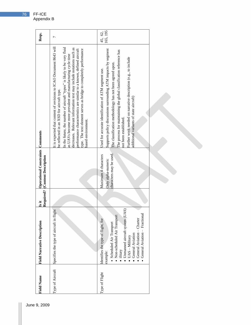
FF-ICE Appendix B
June 9, 2009
76
Req
s.
7
45
, 6
2,
16
5,
19
5
Co
mm
ents
It i
s ex
pec
ted
th
at c
on
ten
t o
f re
vis
ion
s to
IC
AO
Do
cum
ent
86
43
wil
l
be
refl
ecte
d i
n a
n X
SD
for
airc
raft
typ
e.
In t
he
futu
re,
the
nu
mb
er o
f ai
rcra
ft ―
typ
es‖
is l
ikel
y t
o b
e v
ery
flu
id
as U
AV
s b
eco
me
mo
re p
rev
alen
t an
d m
anu
fact
uri
ng
cy
cle
tim
e
dec
reas
es.
Rel
evan
t in
form
atio
n t
ext
may
in
clu
de
no
tati
on
s su
ch a
s
per
form
ance
ch
arac
teri
stic
s ar
e si
mil
ar t
o a
kn
ow
n, d
efin
ed a
ircr
aft
typ
e. T
he
tex
t el
emen
t se
rves
as
bri
dg
e to
co
mp
lete
ly p
erfo
rman
ce
bas
ed e
nv
iro
nm
ent.
Use
d f
or
accu
rate
id
enti
fica
tio
n o
f A
TM
seg
men
t u
se.
Su
pp
ort
s po
licy
dis
cuss
ion
s su
rrou
ndin
g A
TM
im
pac
ts b
y s
egm
ent
Th
e cl
assi
fica
tio
n m
etho
do
log
y h
as n
ot
bee
n a
gre
ed u
po
n.
Th
e p
roce
ss f
or
mai
nta
inin
g t
he
glo
bal
cla
ssif
icat
ion
ref
eren
ce h
as
no
t b
een
est
abli
shed
.
Fu
rth
er w
ork
nee
ded
on n
arra
tiv
e d
escr
ipti
on
(e.
g.,
to
in
clud
e
add
itio
nal
var
ian
ts o
f st
ate
airc
raft
)
Op
era
tio
na
l C
on
stra
ints
(Co
nte
nt
Des
crip
tio
n
Max
imu
m 4
ch
arac
ters
On
ly a
lph
a-nu
mer
ic
char
acte
rs m
ay b
e u
sed
.
Is i
t
Req
uir
ed?
Fie
ld N
arr
ati
ve
Des
crip
tio
n
Sp
ecif
ies
the
typ
e o
f ai
rcra
ft i
n f
lig
ht
Iden
tifi
es t
he
typ
e o
f fl
igh
t, f
or
exam
ple
:
S
ched
ule
d A
ir T
ran
spo
rt
N
on
-sch
edu
led
Air
Tra
nsp
ort
il
itar
y
U
nm
ann
ed a
ircr
aft
syst
em (
UA
S)
U
AS
– M
ilit
ary
G
ener
al A
via
tio
n
G
ener
al A
via
tio
n –
Ch
arte
r
G
ener
al A
via
tio
n –
F
ract
ion
al
Fie
ld N
am
e
Ty
pe
of
Air
craf
t
Ty
pe
of
Fli
gh
t
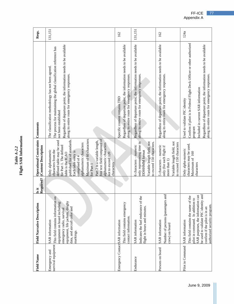
FF-ICE Appendix A
June 9, 2009
77
Req
s.
13
1,1
51
16
2
13
1,1
51
16
2
12
4a
Co
mm
ents
Th
e cl
assi
fica
tio
n m
etho
do
log
y h
as n
ot
bee
n a
gre
ed.
Th
e p
roce
ss f
or
mai
nta
inin
g t
he
glo
bal
cla
ssif
icat
ion
ref
eren
ce h
as
no
t b
een
est
abli
shed
Reg
ard
less
of
dep
artu
re p
oin
t, t
he
info
rmat
ion
nee
ds
to b
e av
aila
ble
alo
ng i
ts e
nti
re r
ou
te f
or
emer
gen
cy r
esp
on
ses.
Sp
ecif
ic c
on
ten
t re
mai
ns
TB
D
Reg
ard
less
of
dep
artu
re p
oin
t, t
he
info
rmat
ion
nee
ds
to b
e av
aila
ble
alo
ng i
ts e
nti
re r
ou
te f
or
emer
gen
cy r
esp
on
ses.
Reg
ard
less
of
dep
artu
re p
oin
t, t
he
info
rmat
ion
nee
ds
to b
e av
aila
ble
alo
ng i
ts e
nti
re r
ou
te f
or
emer
gen
cy r
esp
on
ses.
Reg
ard
less
of
dep
artu
re p
oin
t, t
he
info
rmati
on
nee
ds
to b
e av
aila
ble
alo
ng i
ts e
nti
re r
ou
te f
or
emer
gen
cy r
esp
on
ses.
Use
d t
o v
alid
ate
PIC
id
enti
ty
Co
nfi
rm i
f p
ilo
t is
in
Fed
eral
Fli
gh
t D
eck
Off
icer
or
oth
er a
uth
ori
zed
pro
gra
m
Incl
ud
ed i
n c
urr
ent
SA
R i
nfo
rmat
ion
Reg
ard
less
of
dep
artu
re p
oin
t, t
he
info
rmat
ion
nee
ds
to b
e av
aila
ble
alo
ng i
ts e
nti
re r
ou
te f
or
emer
gen
cy r
esp
on
ses.
Op
era
tio
na
l C
on
stra
ints
(Co
nte
nt
Des
crip
tio
n
On
ly a
lph
anu
mer
ic
char
acte
rs f
rom
th
e
def
ined
tab
le m
ay b
e u
sed
for
Par
t 1
. T
he
def
ined
tab
le i
s th
e IC
AO
pu
bli
shed
lis
t o
f st
and
ard
s.
Eac
h t
able
en
try
is
com
pri
sed
of
4
alp
han
um
eric
ch
arac
ters
Max
imu
m o
f 6
0 c
har
acte
rs
for
Par
t 1
Par
t 2
is
a v
aria
ble
len
gth
,
free
tex
t fi
eld
co
mp
ose
d o
f
alp
han
um
eric
ch
arac
ters
no
t to
ex
ceed
120
char
acte
rs
6 c
har
acte
rs –
nu
mer
ic
on
ly r
epre
sen
tin
g t
ime
in
DD
HH
MM
fo
rmat
Var
iab
le l
eng
th f
ield
, no
t
to e
xce
ed 1
50 c
har
acte
rs.
5 c
har
acte
rs –
nu
mer
ic
on
ly (
for
each
fli
gh
t if
mo
re t
han
1)
Var
iab
le l
eng
th f
ield
, no
t
to e
xce
ed 1
50 c
har
acte
rs
On
ly a
lph
a-nu
mer
ic
char
acte
rs m
ay b
e u
sed
.
Max
imu
m o
f 1
60
char
acte
rs
Is i
t
Req
uir
ed?
Fie
ld N
arr
ati
ve
Des
crip
tio
n
SA
R i
nfo
rmat
ion
Th
is f
ield
co
nta
ins
info
rmat
ion
on
equ
ipm
ent
on
bo
ard
in
clud
ing
:
emer
gen
cy r
adio
, su
rviv
al
equ
ipm
ent,
lif
e ja
cket
s, d
ingh
y
dat
a, a
nd a
ircr
aft
colo
r an
d
mar
kin
gs.
SA
R i
nfo
rmat
ion
Th
is f
ield
co
nta
ins
emer
gen
cy
con
tact
in
form
atio
n.
SA
R i
nfo
rmat
ion
Ind
icat
es t
he
fuel
en
du
ran
ce o
f th
e
flig
ht
in h
ou
rs a
nd
min
ute
s.
SA
R i
nfo
rmat
ion
Nu
mb
er o
f p
erso
ns
(pas
sen
ger
s an
d
crew
) o
n b
oar
d
SA
R i
nfo
rmat
ion
Th
is f
ield
co
nta
ins
the
nam
e o
f th
e
pil
ot
in c
om
man
d. I
n a
dd
itio
n t
o
SA
R p
urp
ose
s, t
he
info
rmat
ion
can
be
use
d t
o v
alid
ate
PIC
id
enti
ty a
nd
con
firm
if
the
pil
ot
is i
n a
n
auth
ori
zed
sec
uri
ty p
rog
ram
.
Fie
ld N
am
e
Em
erg
ency
an
d
surv
ival
eq
uip
men
t
Em
erg
ency
Con
tact
En
du
ran
ce
Per
son
s on
bo
ard
Pil
ot
in C
om
man
d
Ta
ble
A-2
.2
Fli
gh
t S
AR
In
form
ati
on

FF-ICE Appendix B
June 9, 2009
78
Req
s.
99
11
,18
,
45
,181
Co
mm
ents
Th
e cl
assi
fica
tio
n m
etho
do
log
y h
as n
ot
bee
n a
gre
ed t
o.
·
Th
e p
roce
ss f
or
mai
nta
inin
g t
he
glo
bal
cla
ssif
icat
ion
ref
eren
ce h
as
no
t b
een
est
abli
shed
.
· P
rop
ose
d c
on
stra
ints
sup
po
rt a
uto
mat
ed t
ran
sfer
of
up t
o 1
5
ind
ivid
ual
coo
rdin
atio
ns.
P
art
2 t
ext
fiel
d i
s in
ten
ded
to s
upp
ort
var
yin
g g
lob
al n
um
ber
ing
or
no
tati
on m
eth
od
s re
flec
tin
g t
he
nec
essa
ry c
oo
rdin
atio
n
It w
ou
ld b
e b
enef
icia
l to
sp
ecif
y c
ateg
ori
es
and
th
e as
soci
ated
pri
ori
ty t
o a
ssis
t au
tom
atio
n i
n p
lan
nin
g a
nd
ser
vic
ing
of
thes
e
flig
hts
. C
on
figu
rati
on
man
aged
by
IC
AO
.
Op
era
tio
na
l C
on
stra
ints
(Co
nte
nt
Des
crip
tio
n
On
ly a
lph
anu
mer
ic
char
acte
rs f
rom
th
e
def
ined
tab
le m
ay b
e u
sed
for
Par
t 1
.
Th
e d
efin
ed t
able
is
the
ICA
O p
ubli
shed
lis
t o
f
stan
dar
ds.
E
ach
tab
le
entr
y i
s co
mp
rise
d o
f 4
alp
han
um
eric
ch
arac
ters
to
iden
tify
th
e at
trib
ute
of
the
tex
t in
Par
t 2
[ov
erfl
igh
t
auth
ori
zati
on n
um
ber
, et
c]
·
ISO
co
de
for
stat
e u
sed
·
max
imu
m o
f 25
en
trie
s
of
30
alp
han
um
eric
char
acte
rs e
ach
.
Th
e d
efin
ed t
able
is
the
ICA
O p
ubli
shed
lis
t o
f
stan
dar
ds.
Is i
t
Req
uir
ed?
Fie
ld N
arr
ati
ve
Des
crip
tio
n
Th
is f
ield
co
nta
ins
spec
ial
per
mis
sio
ns,
wai
ver
s, D
iplo
mat
ic
Cle
aran
ces,
co
mm
erci
al o
per
atin
g
auth
ori
ty o
r o
ther
per
mis
siv
e
secu
rity
in
form
atio
n
Eq
uip
men
t/p
roce
du
res
for
whic
h t
he
air
crew
is
no
t q
ual
ifie
d –
ev
en
thou
gh
th
e eq
uip
men
t m
ay b
e on
th
e
airc
raft
.
See
No
te 1
, F
ligh
t C
rew
Qu
alif
icat
ion
s, f
or
the
det
ails
of
wh
at
nee
ds
to b
e co
nsi
der
ed i
n t
his
cate
go
ry
Rea
son
s th
at r
equ
ire
spec
ial
han
dli
ng
of
a fl
igh
t b
y A
TS
. C
urr
ent
ST
S/
See
No
te 2
, F
ligh
t S
tatu
s
Info
rmat
ion
fo
r po
ssib
le f
ligh
t st
atu
s
item
s
Fie
ld N
am
e
Acc
ess
Pro
vis
ion
s
Ap
pli
cati
on
s an
d
app
rov
als
Fli
gh
t S
tatu
s
Ta
ble
A-2
.3
Fli
gh
t P
erm
issi
on
In
form
ati
on
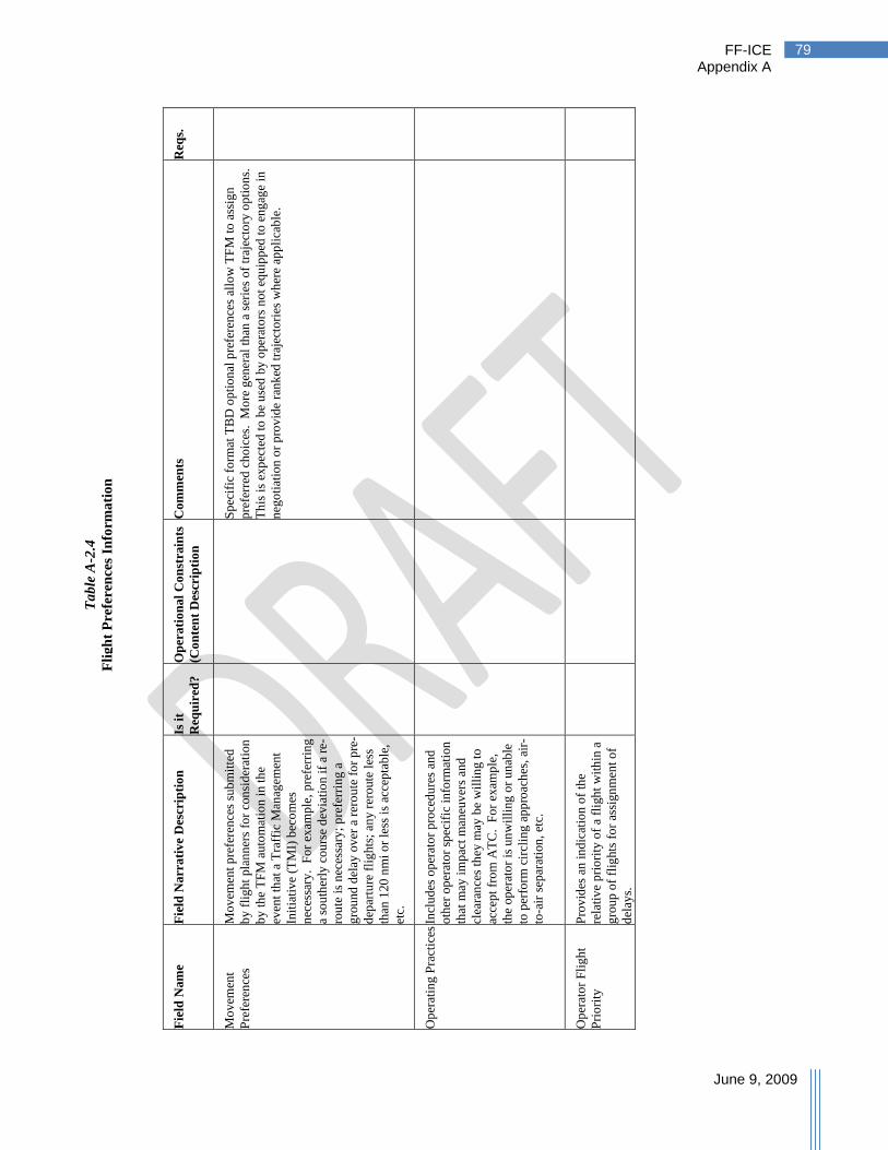
FF-ICE Appendix A
June 9, 2009
79
Req
s.
Co
mm
ents
Sp
ecif
ic f
orm
at T
BD
op
tio
nal
pre
fere
nce
s al
low
TF
M t
o a
ssig
n
pre
ferr
ed c
ho
ices
. M
ore
gen
eral
th
an a
ser
ies
of
traj
ecto
ry o
pti
on
s.
Th
is i
s ex
pec
ted
to
be
use
d b
y o
per
ato
rs n
ot
equ
ipp
ed t
o e
ng
age
in
neg
oti
atio
n o
r p
rov
ide
ran
ked
tra
ject
ori
es w
her
e ap
pli
cab
le.
Op
era
tio
na
l C
on
stra
ints
(Co
nte
nt
Des
crip
tio
n
Is i
t
Req
uir
ed?
Fie
ld N
arr
ati
ve
Des
crip
tio
n
Mo
vem
ent
pre
fere
nce
s su
bm
itte
d
by
fli
gh
t pla
nn
ers
for
con
sid
erat
ion
by
th
e T
FM
au
tom
atio
n i
n t
he
even
t th
at a
Tra
ffic
Man
agem
ent
Init
iati
ve
(TM
I) b
eco
mes
nec
essa
ry.
Fo
r ex
ample
, p
refe
rrin
g
a so
uth
erly
cou
rse
dev
iati
on i
f a
re-
rou
te i
s n
eces
sary
; p
refe
rrin
g a
gro
und
del
ay o
ver
a r
ero
ute
fo
r p
re-
dep
artu
re f
lig
hts
; an
y r
ero
ute
les
s
than
120
nm
i o
r le
ss i
s ac
cep
tab
le,
etc.
Incl
ud
es o
per
ato
r p
roce
du
res
and
oth
er o
per
ato
r sp
ecif
ic i
nfo
rmat
ion
that
may
im
pac
t m
aneu
ver
s an
d
clea
ran
ces
they
may
be
wil
lin
g t
o
acce
pt
fro
m A
TC
. F
or
exam
ple
,
the
op
erat
or
is u
nw
illi
ng
or
un
able
to p
erfo
rm c
ircl
ing
ap
pro
ach
es,
air-
to-a
ir s
epar
atio
n,
etc.
Pro
vid
es a
n i
nd
icat
ion
of
the
rela
tiv
e p
rio
rity
of
a fl
igh
t w
ith
in a
gro
up
of
flig
hts
fo
r as
sign
men
t o
f
del
ays.
Fie
ld N
am
e
Mo
vem
ent
Pre
fere
nce
s
Op
erat
ing
Pra
ctic
es
Op
erat
or
Fli
gh
t
Pri
ori
ty
Ta
ble
A-2
.4
Fli
gh
t P
refe
ren
ces
Info
rma
tio
n
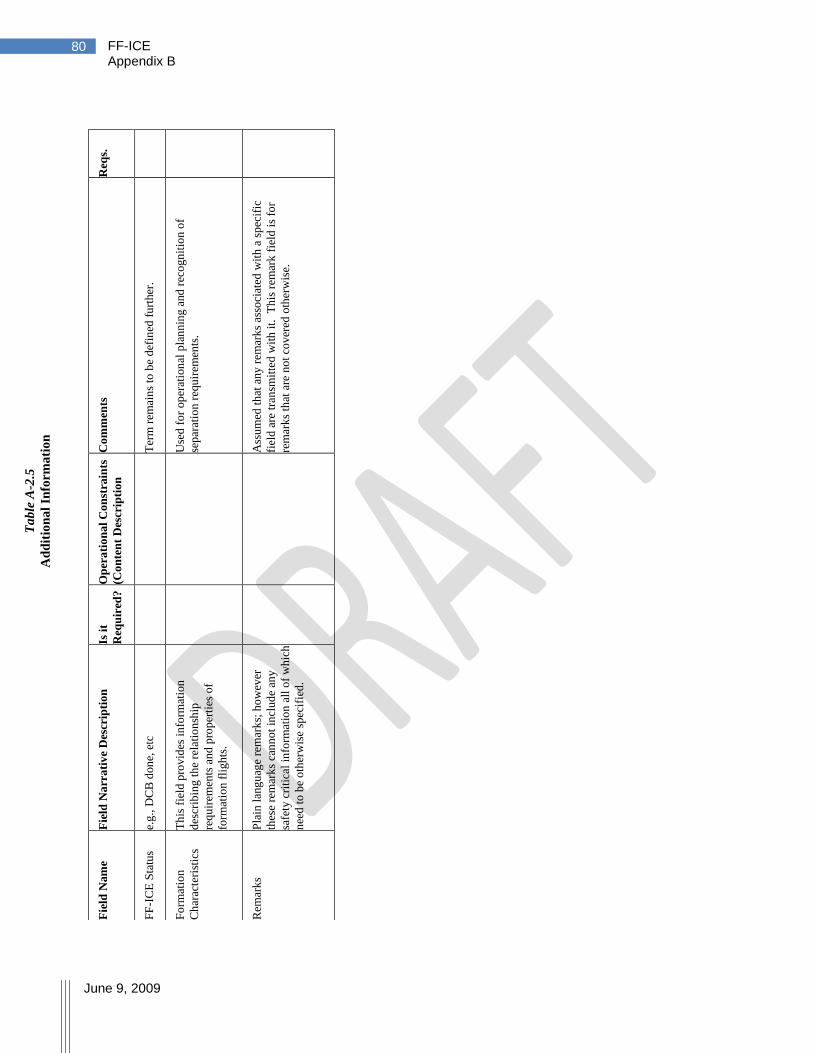
FF-ICE Appendix B
June 9, 2009
80
R
eqs.
Co
mm
ents
Ter
m r
emai
ns
to b
e d
efin
ed f
urt
her
.
Use
d f
or
op
erat
ion
al p
lan
nin
g a
nd
rec
ogn
itio
n o
f
sep
arat
ion
req
uir
emen
ts.
Ass
um
ed t
hat
any
rem
ark
s as
soci
ated
wit
h a
sp
ecif
ic
fiel
d a
re t
ran
smit
ted
wit
h i
t.
Th
is r
emar
k f
ield
is
for
rem
ark
s th
at a
re n
ot
cov
ered
oth
erw
ise.
Op
era
tio
na
l C
on
stra
ints
(Co
nte
nt
Des
crip
tio
n
Is i
t
Req
uir
ed?
Fie
ld N
arr
ati
ve
Des
crip
tio
n
e.g
., D
CB
don
e, e
tc
Th
is f
ield
pro
vid
es i
nfo
rmat
ion
des
crib
ing
th
e re
lati
on
ship
req
uir
emen
ts a
nd p
rop
erti
es o
f
form
atio
n f
ligh
ts.
Pla
in l
ang
uag
e re
mar
ks;
ho
wev
er
thes
e re
mar
ks
can
no
t in
clud
e an
y
safe
ty c
riti
cal
info
rmat
ion
all
of
wh
ich
nee
d t
o b
e o
ther
wis
e sp
ecif
ied
.
Fie
ld N
am
e
FF
-IC
E S
tatu
s
Fo
rmat
ion
Ch
arac
teri
stic
s
Rem
ark
s
Ta
ble
A-2
.5
Ad
dit
ion
al
Info
rma
tio
n
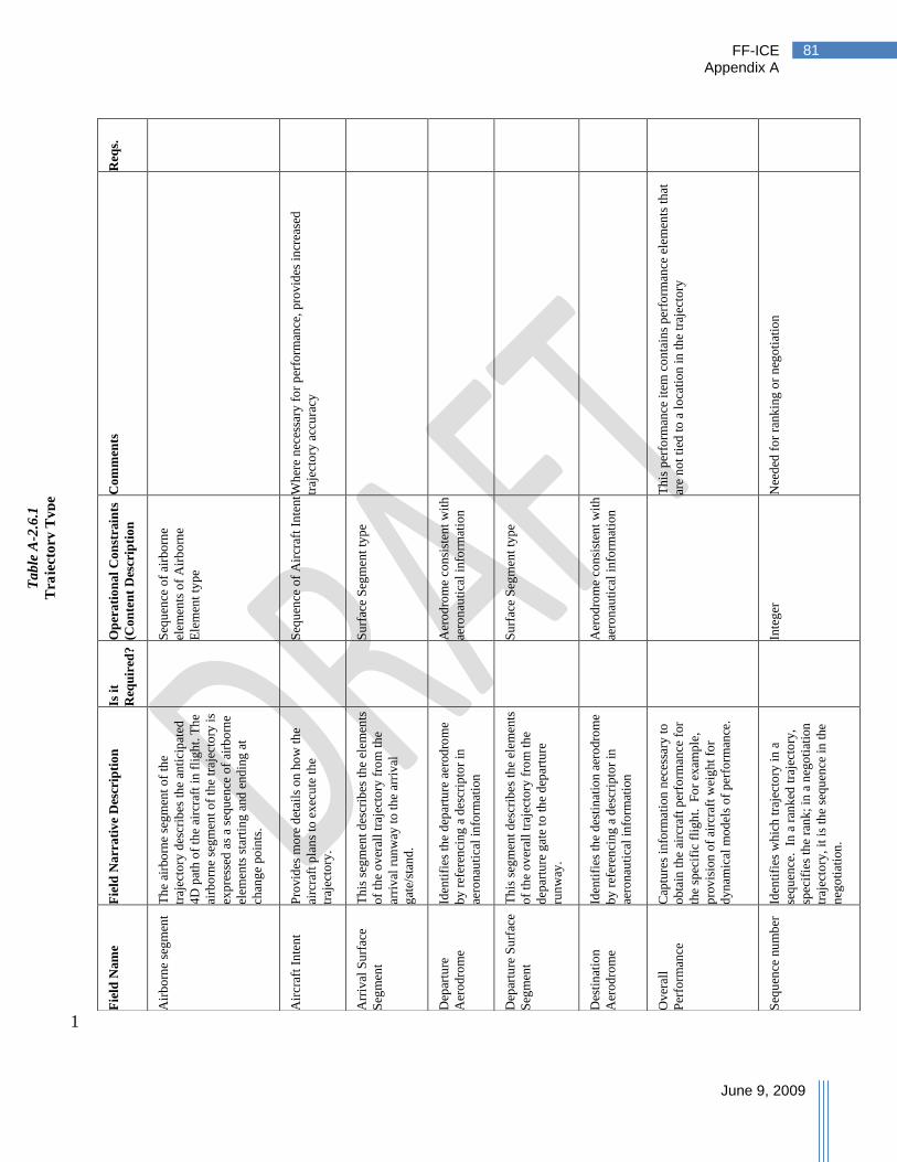
FF-ICE Appendix A
June 9, 2009
81
1
Req
s.
Co
mm
ents
Wh
ere
nec
essa
ry f
or
per
form
ance
, p
rov
ides
in
crea
sed
traj
ecto
ry a
ccu
racy
Th
is p
erfo
rman
ce i
tem
co
nta
ins
per
form
ance
ele
men
ts t
hat
are
no
t ti
ed t
o a
lo
cati
on
in
th
e tr
ajec
tory
Nee
ded
fo
r ra
nk
ing
or
neg
oti
atio
n
Op
era
tio
na
l C
on
stra
ints
(Co
nte
nt
Des
crip
tio
n
Seq
uen
ce o
f ai
rbo
rne
elem
ents
of
Air
bo
rne
Ele
men
t ty
pe
Seq
uen
ce o
f A
ircr
aft
Inte
nt
Su
rfac
e S
egm
ent
typ
e
Aer
od
rom
e co
nsi
sten
t w
ith
aero
nau
tica
l in
form
atio
n
Su
rfac
e S
egm
ent
typ
e
Aer
od
rom
e co
nsi
sten
t w
ith
aero
nau
tica
l in
form
atio
n
Inte
ger
Is i
t
Req
uir
ed?
Fie
ld N
arr
ati
ve
Des
crip
tio
n
Th
e ai
rbo
rne
seg
men
t o
f th
e
traj
ecto
ry d
escr
ibes
th
e an
tici
pat
ed
4D
pat
h o
f th
e ai
rcra
ft i
n f
lig
ht.
Th
e
airb
orn
e se
gm
ent
of
the
traj
ecto
ry i
s
exp
ress
ed a
s a
seq
uen
ce o
f ai
rbo
rne
elem
ents
sta
rtin
g a
nd
end
ing
at
chan
ge
po
ints
.
Pro
vid
es m
ore
det
ails
on h
ow
th
e
airc
raft
pla
ns
to e
xec
ute
th
e
traj
ecto
ry.
Th
is s
egm
ent
des
crib
es t
he
elem
ents
of
the
ov
eral
l tr
ajec
tory
fro
m t
he
arri
val
run
way
to t
he
arri
val
gat
e/st
and
.
Iden
tifi
es t
he
dep
artu
re a
ero
dro
me
by
ref
eren
cing
a d
escr
ipto
r in
aero
nau
tica
l in
form
atio
n
Th
is s
egm
ent
des
crib
es t
he
elem
ents
of
the
ov
eral
l tr
ajec
tory
fro
m t
he
dep
artu
re g
ate
to t
he
dep
artu
re
run
way
.
Iden
tifi
es t
he
des
tin
atio
n a
ero
dro
me
by
ref
eren
cing
a d
escr
ipto
r in
aero
nau
tica
l in
form
atio
n
Cap
ture
s in
form
atio
n n
eces
sary
to
ob
tain
th
e ai
rcra
ft p
erfo
rman
ce f
or
the
spec
ific
fli
gh
t.
Fo
r ex
amp
le,
pro
vis
ion
of
airc
raft
wei
gh
t fo
r
dy
nam
ical
mo
del
s o
f p
erfo
rman
ce.
Iden
tifi
es w
hic
h t
raje
cto
ry i
n a
seq
uen
ce.
In a
ran
ked
tra
ject
ory
,
spec
ifie
s th
e ra
nk
; in
a n
ego
tiat
ion
traj
ecto
ry,
it i
s th
e se
qu
ence
in
the
neg
oti
atio
n.
Fie
ld N
am
e
Air
bo
rne
seg
men
t
Air
craf
t In
ten
t
Arr
ival
Su
rfac
e
Seg
men
t
Dep
artu
re
Aer
od
rom
e
Dep
artu
re S
urf
ace
Seg
men
t
Des
tin
atio
n
Aer
od
rom
e
Ov
eral
l
Per
form
ance
Seq
uen
ce n
um
ber
Ta
ble
A-2
.6.1
Tra
jecto
ry T
yp
e
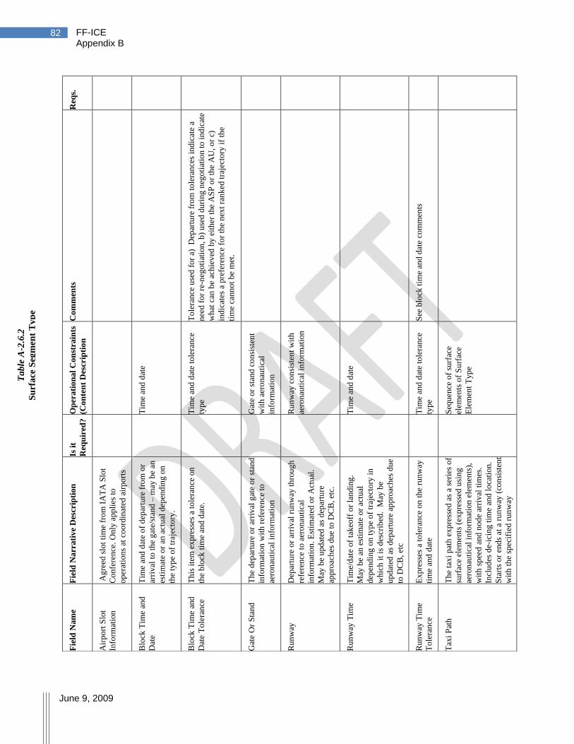
FF-ICE Appendix B
June 9, 2009
82
Req
s.
Co
mm
ents
To
lera
nce
use
d f
or
a)
Dep
artu
re f
rom
to
lera
nce
s in
dic
ate
a
nee
d f
or
re-n
egoti
atio
n, b
) u
sed
du
ring
neg
oti
atio
n t
o i
nd
icat
e
wh
at c
an b
e ac
hie
ved
by
eit
her
the
AS
P o
r th
e A
U, o
r c)
ind
icat
es a
pre
fere
nce
fo
r th
e n
ext
ran
ked
tra
ject
ory
if
the
tim
e ca
nn
ot
be
met
.
See
blo
ck t
ime
and
dat
e co
mm
ents
Op
era
tio
na
l C
on
stra
ints
(Co
nte
nt
Des
crip
tio
n
Tim
e an
d d
ate
Tim
e an
d d
ate
tole
ran
ce
typ
e
Gat
e o
r st
and
co
nsi
sten
t
wit
h a
ero
nau
tica
l
info
rmat
ion
Ru
nw
ay c
on
sist
ent
wit
h
aero
nau
tica
l in
form
atio
n
Tim
e an
d d
ate
Tim
e an
d d
ate
tole
ran
ce
typ
e
Seq
uen
ce o
f su
rfac
e
elem
ents
of
Su
rfac
e
Ele
men
t T
yp
e
Is i
t
Req
uir
ed?
Fie
ld N
arr
ati
ve
Des
crip
tio
n
Ag
reed
slo
t ti
me
fro
m I
AT
A S
lot
Co
nfe
ren
ce.
On
ly a
pp
lies
to
op
erat
ion
s at
coo
rdin
ated
air
po
rts
Tim
e an
d d
ate
of
dep
artu
re f
rom
or
arri
val
to
th
e g
ate/
stan
d –
may
be
an
esti
mat
e o
r an
act
ual
dep
end
ing o
n
the
typ
e o
f tr
ajec
tory
.
Th
is i
tem
exp
ress
es a
to
lera
nce
on
the
blo
ck t
ime
and
dat
e.
Th
e d
epar
ture
or
arri
val
gat
e o
r st
and
info
rmat
ion
wit
h r
efer
ence
to
aero
nau
tica
l in
form
atio
n
Dep
artu
re o
r ar
riv
al r
un
way
th
roug
h
refe
ren
ce t
o a
ero
nau
tica
l
info
rmat
ion
. E
stim
ated
or
Act
ual
.
May
be
upd
ated
as
dep
artu
re
app
roac
hes
du
e to
DC
B,
etc.
Tim
e/d
ate
of
tak
eoff
or
lan
din
g.
May
be
an e
stim
ate
or
actu
al
dep
endin
g o
n t
yp
e o
f tr
ajec
tory
in
wh
ich
it
is d
escr
ibed
. M
ay b
e
up
dat
ed a
s d
epar
ture
ap
pro
ach
es d
ue
to D
CB
, et
c
Ex
pre
sses
a t
ole
ran
ce o
n t
he
run
way
tim
e an
d d
ate
Th
e ta
xi
pat
h e
xp
ress
ed a
s a
seri
es o
f
surf
ace
elem
ents
(ex
pre
ssed
usi
ng
aero
nau
tica
l in
form
atio
n e
lem
ents
),
wit
h s
pee
d a
nd
nod
e ar
riv
al t
imes
.
Incl
ud
es d
e-ic
ing t
ime
and l
oca
tion
.
Sta
rts
or
end
s at
a r
un
way
(co
nsi
sten
t
wit
h t
he
spec
ifie
d r
un
way
Fie
ld N
am
e
Air
po
rt S
lot
Info
rmat
ion
Blo
ck T
ime
and
Dat
e
Blo
ck T
ime
and
Dat
e T
ole
ran
ce
Gat
e O
r S
tan
d
Ru
nw
ay
Ru
nw
ay T
ime
Ru
nw
ay T
ime
To
lera
nce
Tax
i P
ath
Ta
ble
A-2
.6.2
Su
rfa
ce S
egm
ent
Ty
pe
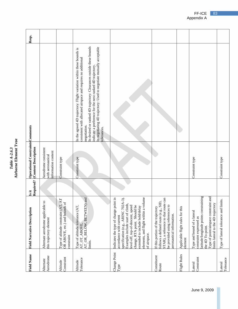
FF-ICE Appendix A
June 9, 2009
83
Req
s.
Co
mm
ents
In t
he
agre
ed 4
D t
raje
cto
ry:
Fli
ght
var
iati
on
wit
hin
th
ese
bo
un
ds
is
con
sist
ent
wit
h a
llo
cate
d a
irsp
ace
and
req
uir
es n
o a
dd
itio
nal
neg
oti
atio
n.
In d
esir
ed o
r ra
nk
ed 4
D t
raje
cto
ry:
Cle
aran
ces
ou
tsid
e th
ese
bou
nd
s
ind
icat
e a
pre
fere
nce
fo
r th
e n
ext
ran
ked
4D
tra
ject
ory
.
In n
ego
tiat
ing 4
D t
raje
cto
ry:
Use
d t
o n
ego
tiat
e m
utu
ally
acc
epta
ble
tole
ran
ces.
Op
era
tio
na
l C
on
stra
ints
(Co
nte
nt
Des
crip
tio
n
Aer
od
rom
e co
nsi
sten
t
wit
h a
ero
nau
tica
l
info
rmat
ion
con
ten
t
Co
nst
rain
t ty
pe
Co
nst
rain
t ty
pe
Co
nst
rain
t ty
pe
Co
nst
rain
t ty
pe
Is i
t
Req
uir
ed?
Fie
ld N
arr
ati
ve
Des
crip
tio
n
Alt
ern
ate
aero
dro
me
appli
cab
le t
o
this
tra
ject
ory
ele
men
t
Ty
pe
of
alti
tud
e co
nst
rain
t (A
T, A
T
OR
AB
OV
E,
etc.
) an
d b
ou
nd
s o
f
con
stra
int
Ty
pe
of
alti
tud
e to
lera
nce
(A
T,
AT
_O
T_
AB
OV
E,
AT
_O
R_
BE
LO
W, B
ET
WE
EN
) an
d
lim
its.
Ind
icat
es t
he
typ
e o
f ch
ang
e po
int
in
acco
rdan
ce w
ith
cu
rren
t
spec
ific
atio
n (
e.g
., A
RIN
C 7
02
A-3
).
Ex
amp
les
incl
ud
e st
art
of
clim
b,
lev
el-o
ff,
top
-of-
des
cen
t, s
pee
d
chan
ge,
RT
A p
oin
t.
Sh
ou
ld b
e
exte
nd
ed t
o i
ncl
ud
e ho
ld/d
elay
elem
ents
, an
d f
lig
ht
wit
hin
a v
olu
me
of
airs
pac
e.
If t
his
po
rtio
n o
f th
e tr
ajec
tory
foll
ow
s a
def
ined
rou
te (
e.g
., S
ID,
ST
AR
), a
ref
eren
ce t
o t
hat
rou
te c
an
be
pro
vid
ed u
sing
ref
eren
ces
to
aero
nau
tica
l in
form
atio
n.
Ap
pli
cab
le f
ligh
t ru
les
for
this
elem
ent
Ty
pe
and
bou
nd
of
a la
tera
l
con
stra
int
exp
ress
ed a
s
lati
tud
e/lo
ng
itu
de
po
ints
con
stra
inin
g
the
4D
To
-po
int.
Ty
pe
of
po
int/
airs
pac
e co
nst
rain
t an
d
lim
its
late
ral
to t
he
4D
tra
ject
ory
Ty
pe
of
late
ral
tole
ran
ce a
nd
lim
its.
Fie
ld N
am
e
Alt
ern
ate
Aer
od
rom
e
Alt
itu
de
Co
nst
rain
t
Alt
itu
de
To
lera
nce
Ch
ang
e P
oin
t
Ty
pe
Co
nst
itu
ent
Ro
ute
Fli
gh
t R
ule
s
Lat
eral
Co
nst
rain
t
Lat
eral
To
lera
nce
Ta
ble
A-2
.6.3
Air
bo
rne
Ele
men
t T
yp
e

FF-ICE Appendix B
June 9, 2009
84
R
eqs.
Co
mm
ents
Op
era
tio
na
l C
on
stra
ints
(Co
nte
nt
Des
crip
tio
n
Per
form
ance
ty
pe
Po
int
con
sist
ent
wit
h
aero
nau
tica
l in
form
atio
n
Co
nst
rain
t ty
pe
Co
nst
rain
t ty
pe
Tim
e co
nst
rain
t ty
pe
Tim
e co
nst
rain
t ty
pe
Is i
t
Req
uir
ed?
Fie
ld N
arr
ati
ve
Des
crip
tio
n
Ind
icat
es r
elev
ant
per
form
ance
val
ues
fo
r th
e n
ext
elem
ent
of
the
traj
ecto
ry.
Th
ese
val
ues
are
exp
ress
ed w
ith
th
e tr
ajec
tory
as
the
per
form
ance
in
form
atio
n c
an v
ary
alo
ng t
he
traj
ecto
ry.
Des
crib
es t
he
refe
ren
ce p
oin
t u
sing
aero
nau
tica
l in
form
atio
n (
e.g.,
nam
ed p
oin
t). T
his
in
form
atio
n
rep
rese
nts
to
day
‘s ―
way
poin
ts‖
on
the
rou
te.
Ind
icat
or
that
th
e fl
igh
t is
exp
ecte
d
to b
e o
per
atin
g i
n a
cco
rdan
ce w
ith
reg
ula
tion
s is
sued
by
th
e re
lev
ant
stat
e fo
r ai
rcra
ft o
per
atin
g a
s 'S
tate
Air
craf
t',
as p
er A
rtic
le 3
of
the
"Co
nv
enti
on o
n I
nte
rnat
ion
al C
ivil
Av
iati
on
" IC
AO
Do
cum
ent
73
00
/9,
and
fo
r ai
rcra
ft o
per
atin
g i
n
acco
rdan
ce w
ith
sta
te r
egula
tion
s fo
r
no
n-s
tan
dar
d f
lyin
g a
ctiv
itie
s,
no
rmal
ly t
hro
ug
h t
he
use
of
rese
rved
airs
pac
e.
Ind
icat
es t
he
airs
pee
d f
or
the
po
int
as
CA
S o
r M
ach.
Ty
pe
of
spee
d c
on
stra
int
and
lim
its
Ty
pe
of
spee
d t
ole
ran
ce a
nd l
imit
s
Ty
pe
of
tim
e co
nst
rain
t (A
T,
BE
TW
EE
N)
and
lim
its
(No
t
con
sist
ent
wit
h A
RIN
C 7
02
A-3
); c
an
be
a p
oin
t-in
-sp
ace
met
erin
g t
ime.
Ty
pe
of
tim
e to
lera
nce
an
d l
imit
s
Fie
ld N
am
e
Per
form
ance
Ref
eren
ce P
oin
t
Sp
ecia
l
Req
uir
emen
ts
Sp
eed
Sp
eed
Con
stra
int
Sp
eed
To
lera
nce
Tim
e C
on
stra
int
Tim
e T
ole
ran
ce
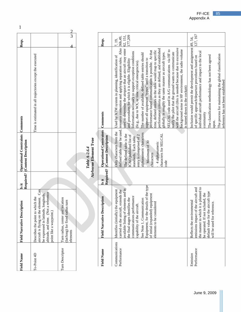
FF-ICE Appendix A
June 9, 2009
85
1 2 3
4 Req
s.
Co
mm
ents
Tim
e is
est
imat
ed i
n a
ll t
raje
cto
ries
ex
cep
t th
e ex
ecu
ted
Op
era
tio
na
l C
on
stra
ints
(Co
nte
nt
Des
crip
tio
n
Is i
t
Req
uir
ed?
Fie
ld N
arr
ati
ve
Des
crip
tio
n
Des
crib
es t
he
po
int
to w
hic
h t
he
airc
raft
is
fly
ing
on
th
e el
emen
t. C
an
be
exp
ress
ed i
n l
atit
ud
e, l
on
git
ude,
alti
tud
e, a
nd t
ime.
(N
ot
a re
fere
nce
po
int
lik
e a
way
po
int.
)
Tu
rn r
adiu
s, c
ente
r an
d l
oca
tio
n
(lat
/lo
ng
) fo
r fi
xed
rad
ius
turn
elem
ents
Fie
ld N
am
e
To
-Poin
t 4
D
Tu
rn D
escr
ipto
r
Req
s.
7,
19
,
36
b,4
9,
62
, 1
51
,
17
7,2
09
49
, 5
4,
12
7,
16
7
Co
mm
ents
Use
d b
y A
TM
sy
stem
in
pla
nn
ing,
iden
tifi
cati
on
of
reso
urc
e co
nte
nti
on
and
app
lyin
g s
epar
atio
n r
ule
s.
Als
o
use
d t
o d
eter
min
e th
e ai
rsp
ace
that
an
air
craf
t m
ay e
nte
r
and
pro
ced
ure
s fo
r w
hic
h i
t is
eli
gib
le. E
lig
ibil
ity
info
rmat
ion
nec
essa
ry t
o s
up
po
rt e
xce
pti
on c
ond
itio
ns
(fe.
g.,
du
e to
WX
, o
r ti
me
crit
ical
em
erg
enci
es).
Th
e nu
mb
er o
f av
aila
ble
, d
efin
ed t
able
en
trie
s sh
ou
ld
sup
po
rt a
ll e
qu
ipm
ent
―ty
pes
‖ u
nti
l a
tran
siti
on
to
per
form
ance
bas
ed c
om
mu
nic
atio
n i
s po
ssib
le. A
t th
at
tim
e, d
efin
ed e
ntr
ies
in t
he
tab
le w
ou
ld m
ap t
o s
pec
ific
per
form
ance
cri
teri
a as
th
ey a
re d
efin
ed,
and
est
abli
shed
glo
bal
ly i
n r
oug
hly
th
e sa
me
man
ner
as
airc
raft
ty
pes
.
SE
LC
AL
cod
e u
sed
in
A/G
co
mm
un
icat
ion
s v
ia H
F t
o
no
tify
th
e p
ilo
t th
at t
he
gro
un
d w
ants
to
co
mm
un
icat
e
wit
h t
he
airc
raft
(th
is i
s n
eed
ed b
ecau
se d
ue
to e
xce
ssiv
e
bac
kg
rou
nd
no
ise
in H
F e
nv
iro
nm
ent,
th
e ra
dio
vo
lum
e
is t
urn
ed d
ow
n i
n t
he
cock
pit
)
Incl
usi
on
wou
ld p
erm
it t
he
dev
elo
pm
ent
and
ass
ign
men
t
of
spec
ific
ap
pro
ach
/dep
artu
re p
roce
du
res
bas
ed o
n
ind
ivid
ual
air
craf
t p
erfo
rman
ce a
nd
im
pac
t to
th
e lo
cal
com
mu
nit
y
Th
e cl
assi
fica
tio
n m
etho
do
log
y h
as n
ot
bee
n a
gre
ed
up
on
.
Th
e p
roce
ss f
or
mai
nta
inin
g t
he
glo
bal
cla
ssif
icat
ion
refe
ren
ce h
as n
ot
bee
n e
stab
lish
ed
Op
era
tio
na
l C
on
stra
ints
(Co
nte
nt
Des
crip
tio
n
On
ly c
har
acte
rs f
rom
th
e
def
ined
tab
le m
ay b
e u
sed
.
Th
e d
efin
ed t
able
is
the
ICA
O p
ubli
shed
lis
t o
f
stan
dar
ds.
E
ach
tab
le
entr
y i
s co
mp
rise
d o
f 2
alp
han
um
eric
ch
arac
ters
·
Max
imu
m o
f 3
0
char
acte
rs
·
4 a
lph
anu
mer
ic
char
acte
rs f
or
SE
LC
AL
cod
e
Is i
t
Req
uir
ed?
Fie
ld N
arr
ati
ve
Des
crip
tio
n
Iden
tifi
es (
init
iall
y)
the
equ
ipm
ent
carr
ied
on
th
e ai
rcra
ft,
exte
nd
s th
e
avai
lab
le l
isti
ng
of
elem
ents
an
d i
n
the
fin
al s
tag
es i
den
tifi
es t
he
com
mu
nic
atio
ns
per
form
ance
cap
abil
ity o
f th
e ai
rcra
ft.
See
No
te 1
, C
om
mu
nic
atio
n
Eq
uip
men
t, f
or
the
det
ails
of
the
typ
e
of
init
ial
(exp
and
ed)
equ
ipm
ent
elem
ents
to
be
con
sid
ered
Ref
lect
s th
e en
vir
on
men
tal
emis
sio
ns
imp
act
of
the
airc
raft
an
d
the
man
ner
in
wh
ich
it
is p
lann
ed t
o
be
op
erat
ed.
If n
ot
incl
ud
ed, th
e
def
ault
val
ue
for
the
airc
raft
ty
pe
wil
l b
e u
sed
fo
r re
fere
nce
.
Fie
ld N
am
e
Co
mm
un
icat
ion
s
Per
form
ance
Em
issi
on
Per
form
ance
Ta
ble
A-2
.6.4
Air
bo
rne
Ele
men
t T
yp
e
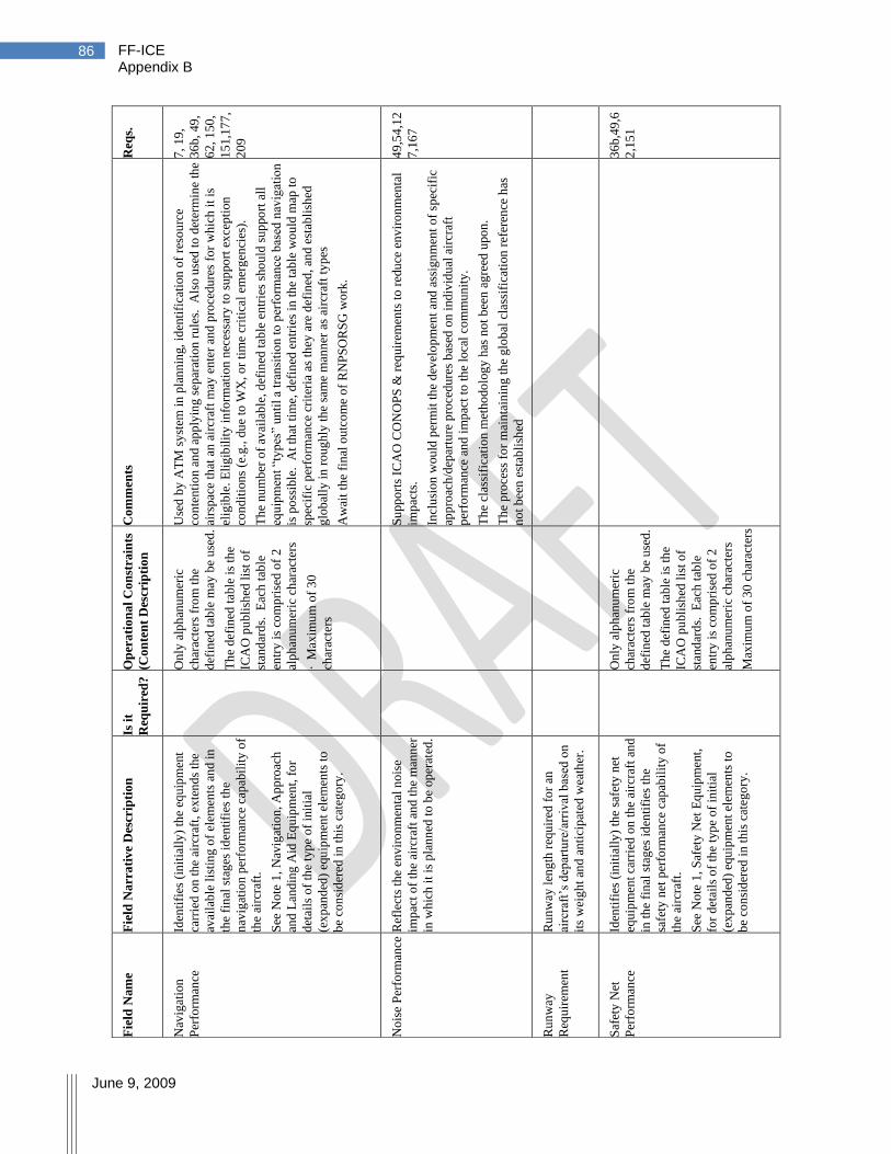
FF-ICE Appendix B
June 9, 2009
86
Req
s.
7,
19
,
36
b,
49
,
62
, 1
50
,
15
1,1
77
,
20
9
49
,54
,12
7,1
67
36
b,4
9,6
2,1
51
Co
mm
ents
Use
d b
y A
TM
sy
stem
in p
lan
nin
g,
iden
tifi
cati
on
of
reso
urc
e
con
ten
tio
n a
nd a
pp
lyin
g s
epar
atio
n r
ule
s. A
lso
use
d t
o d
eter
min
e th
e
airs
pac
e th
at a
n a
ircr
aft
may
en
ter
and
pro
cedu
res
for
wh
ich
it
is
elig
ible
. E
lig
ibil
ity i
nfo
rmat
ion n
eces
sary
to
sup
po
rt e
xce
pti
on
con
dit
ion
s (e
.g., d
ue
to W
X, o
r ti
me
crit
ical
em
erg
enci
es).
Th
e nu
mb
er o
f av
aila
ble
, d
efin
ed t
able
en
trie
s sh
ou
ld s
up
po
rt a
ll
equ
ipm
ent
―ty
pes
‖ un
til
a tr
ansi
tio
n t
o p
erfo
rman
ce b
ased
nav
igat
ion
is p
oss
ible
. A
t th
at t
ime,
def
ined
en
trie
s in
th
e ta
ble
wo
uld
map
to
spec
ific
per
form
ance
cri
teri
a as
th
ey a
re d
efin
ed, an
d e
stab
lish
ed
glo
bal
ly i
n r
oug
hly
th
e sa
me
man
ner
as
airc
raft
ty
pes
Aw
ait
the
fin
al o
utc
om
e o
f R
NP
SO
RS
G w
ork
.
Su
pp
ort
s IC
AO
CO
NO
PS
& r
equir
emen
ts t
o r
edu
ce e
nv
iro
nm
enta
l
imp
acts
.
Incl
usi
on
wou
ld p
erm
it t
he
dev
elo
pm
ent
and
ass
ign
men
t o
f sp
ecif
ic
app
roac
h/d
epar
ture
pro
cedu
res
bas
ed o
n i
nd
ivid
ual
air
craf
t
per
form
ance
an
d i
mp
act
to t
he
loca
l co
mm
un
ity
.
Th
e cl
assi
fica
tio
n m
etho
do
log
y h
as n
ot
bee
n a
gre
ed u
po
n.
Th
e p
roce
ss f
or
mai
nta
inin
g t
he
glo
bal
cla
ssif
icat
ion
ref
eren
ce h
as
no
t b
een
est
abli
shed
Op
era
tio
na
l C
on
stra
ints
(Co
nte
nt
Des
crip
tio
n
On
ly a
lph
anu
mer
ic
char
acte
rs f
rom
th
e
def
ined
tab
le m
ay b
e u
sed
.
Th
e d
efin
ed t
able
is
the
ICA
O p
ubli
shed
lis
t o
f
stan
dar
ds.
E
ach
tab
le
entr
y i
s co
mp
rise
d o
f 2
alp
han
um
eric
ch
arac
ters
· M
axim
um
of
30
char
acte
rs
On
ly a
lph
anu
mer
ic
char
acte
rs f
rom
th
e
def
ined
tab
le m
ay b
e u
sed
.
Th
e d
efin
ed t
able
is
the
ICA
O p
ubli
shed
lis
t o
f
stan
dar
ds.
E
ach
tab
le
entr
y i
s co
mp
rise
d o
f 2
alp
han
um
eric
ch
arac
ters
Max
imu
m o
f 3
0 c
har
acte
rs
Is i
t
Req
uir
ed?
Fie
ld N
arr
ati
ve
Des
crip
tio
n
Iden
tifi
es (
init
iall
y)
the
equ
ipm
ent
carr
ied
on
th
e ai
rcra
ft,
exte
nd
s th
e
avai
lab
le l
isti
ng
of
elem
ents
an
d i
n
the
fin
al s
tag
es i
den
tifi
es t
he
nav
igat
ion p
erfo
rman
ce c
apab
ilit
y o
f
the
airc
raft
.
See
No
te 1
, N
avig
atio
n, A
pp
roac
h
and
Lan
din
g A
id E
qu
ipm
ent,
fo
r
det
ails
of
the
typ
e o
f in
itia
l
(ex
pan
ded
) eq
uip
men
t el
emen
ts t
o
be
con
sid
ered
in t
his
cat
ego
ry.
Ref
lect
s th
e en
vir
on
men
tal
no
ise
imp
act
of
the
airc
raft
an
d t
he
man
ner
in w
hic
h i
t is
pla
nn
ed t
o b
e op
erat
ed.
Ru
nw
ay l
eng
th r
equ
ired
fo
r an
airc
raft
‘s d
epar
ture
/arr
ival
bas
ed o
n
its
wei
gh
t an
d a
nti
cip
ated
wea
ther
.
Iden
tifi
es (
init
iall
y)
the
safe
ty n
et
equ
ipm
ent
carr
ied
on
th
e ai
rcra
ft a
nd
in t
he
fin
al s
tag
es i
den
tifi
es t
he
safe
ty n
et p
erfo
rman
ce c
apab
ilit
y o
f
the
airc
raft
.
See
No
te 1
, S
afet
y N
et E
qu
ipm
ent,
for
det
ails
of
the
typ
e o
f in
itia
l
(ex
pan
ded
) eq
uip
men
t el
emen
ts t
o
be
con
sid
ered
in t
his
cat
ego
ry.
Fie
ld N
am
e
Nav
igat
ion
Per
form
ance
No
ise
Per
form
ance
Ru
nw
ay
Req
uir
emen
t
Saf
ety
Net
Per
form
ance

FF-ICE Appendix A
June 9, 2009
87
R
eqs.
7,1
9,3
6b,
49
,62
,15
1,1
77
,20
9
31
,49
,54,
62
,111
Co
mm
ents
Use
d b
y A
TM
sy
stem
in p
lan
nin
g,
iden
tifi
cati
on
of
reso
urc
e
con
ten
tio
n,
and
app
lyin
g s
epar
atio
n r
ule
s.
Als
o u
sed t
o d
eter
min
e th
e
airs
pac
e th
at a
n a
ircr
aft
may
en
ter
and
pro
cedu
res
for
wh
ich
it
is
elig
ible
. E
lig
ibil
ity
in
form
atio
n n
eces
sary
to
sup
po
rt e
xce
pti
on
con
dit
ion
s (e
.g., d
ue
to W
X, o
r ti
me
crit
ical
em
erg
enci
es).
Th
e nu
mb
er o
f av
aila
ble
, d
efin
ed t
able
en
trie
s sh
ou
ld s
up
po
rt a
ll
equ
ipm
ent
―ty
pes
‖ un
til
a tr
ansi
tio
n t
o p
erfo
rman
ce b
ased
surv
eill
ance
is
po
ssib
le.
At
that
tim
e, d
efin
ed e
ntr
ies
in t
he
table
wo
uld
map
to
sp
ecif
ic p
erfo
rman
ce c
rite
ria
as t
hey
are
def
ined
, and
esta
bli
shed
glo
bal
ly i
n r
oug
hly
the
sam
e m
ann
er a
s ai
rcra
ft t
yp
es
Req
uir
ed d
ue
to s
afet
y c
on
sid
erat
ion
s
Su
pp
ort
s IC
AO
CO
NO
PS
& r
equir
emen
ts t
o i
ncr
ease
saf
ety
.
Rec
og
niz
es d
iffe
rin
g i
mp
act
of
wak
e b
ased
on
air
craf
t co
nfi
gu
rati
on
[arr
ival
/dep
artu
re v
s. ―
cru
ise‖
]
Rec
og
niz
es t
he
po
tenti
al f
or
the
sam
e ―t
yp
e‖ o
f ai
rcra
ft m
od
el t
o
hav
e d
iffe
ren
t w
ake
imp
acts
bas
ed o
n i
nd
ivid
ual
op
erat
ing
pro
ced
ure
s o
r ch
ang
es t
o i
nd
ivid
ual
air
fram
es (
win
gle
ts)
that
may
no
t
mee
t th
e cr
iter
ia t
o e
stab
lish
a n
ew ―
typ
e.‖
T
he
op
erat
ing p
roce
dure
s
incl
ud
es t
he
dif
fere
nce
in
per
form
ance
wh
en a
ircr
aft
is ―
max
ed –
ou
t‖ v
s. e
mp
ty o
r fe
rry
fli
gh
ts.
Th
e cl
assi
fica
tio
n m
etho
do
log
y h
as n
ot
bee
n a
gre
ed.
Th
e p
roce
ss f
or
mai
nta
inin
g t
he
glo
bal
cla
ssif
icat
ion
ref
eren
ce h
as
no
t b
een
est
abli
shed
.
Op
en p
end
ing
co
ord
inat
ion w
ith
ap
pro
pri
ate
enti
ty.
Op
era
tio
na
l C
on
stra
ints
(Co
nte
nt
Des
crip
tio
n
On
ly a
lph
anu
mer
ic
char
acte
rs f
rom
th
e
def
ined
tab
le m
ay b
e u
sed
.
Th
e d
efin
ed t
able
is
the
ICA
O p
ubli
shed
lis
t o
f
stan
dar
ds.
E
ach
tab
le
entr
y i
s co
mp
rise
d o
f 2
alp
han
um
eric
ch
arac
ters
Max
imu
m o
f 3
0 c
har
acte
rs
Use
d b
y A
TM
sy
stem
in
pla
nnin
g,
and
exp
ecta
tio
n
of
resp
on
ses
fro
m a
ircr
aft.
Th
e nu
mb
er o
f av
aila
ble
,
def
ined
tab
le e
ntr
ies
sho
uld
su
pp
ort
all
equ
ipm
ent
―ty
pes
‖ un
til
a
tran
siti
on
to
per
form
ance
bas
ed s
afet
y-n
et i
s
po
ssib
le. A
t th
at t
ime,
def
ined
en
trie
s in
th
e ta
ble
wo
uld
map
to
sp
ecif
ic
per
form
ance
cri
teri
a as
they
are
def
ined
, an
d
esta
bli
shed
glo
bal
ly i
n
roug
hly
th
e sa
me
man
ner
as a
ircr
aft
typ
es.
Is i
t
Req
uir
ed?
Fie
ld N
arr
ati
ve
Des
crip
tio
n
Iden
tifi
es (
init
iall
y)
the
equ
ipm
ent
carr
ied
on
th
e ai
rcra
ft,
exte
nd
s th
e
avai
lab
le l
isti
ng
of
elem
ents
an
d i
n
the
fin
al s
tag
es i
den
tifi
es t
he
surv
eill
ance
per
form
ance
cap
abil
ity
of
the
airc
raft
.
See
No
te 1
, S
urv
eill
ance
Equ
ipm
ent,
for
det
ails
of
the
typ
e o
f in
itia
l
(ex
pan
ded
) eq
uip
men
t el
emen
ts t
o
be
con
sid
ered
in t
his
cat
ego
ry
Th
is f
ield
id
enti
fies
th
e w
ake
turb
ule
nce
im
pac
t o
f th
e fl
igh
t as
a
resu
lt o
f th
e m
ann
er i
n w
hic
h i
t is
pla
nn
ed t
o b
e o
per
ated
. T
his
wil
l b
e
spec
ifie
d a
long
th
e tr
ajec
tory
an
d s
o
it a
llo
ws
elem
ents
fo
r d
epar
ture
, en
rou
te a
nd
arr
ival
ph
ases
of
flig
ht.
Fie
ld N
am
e
Su
rvei
llan
ce
Per
form
ance
Wak
e T
urb
ule
nce
Per
form
ance
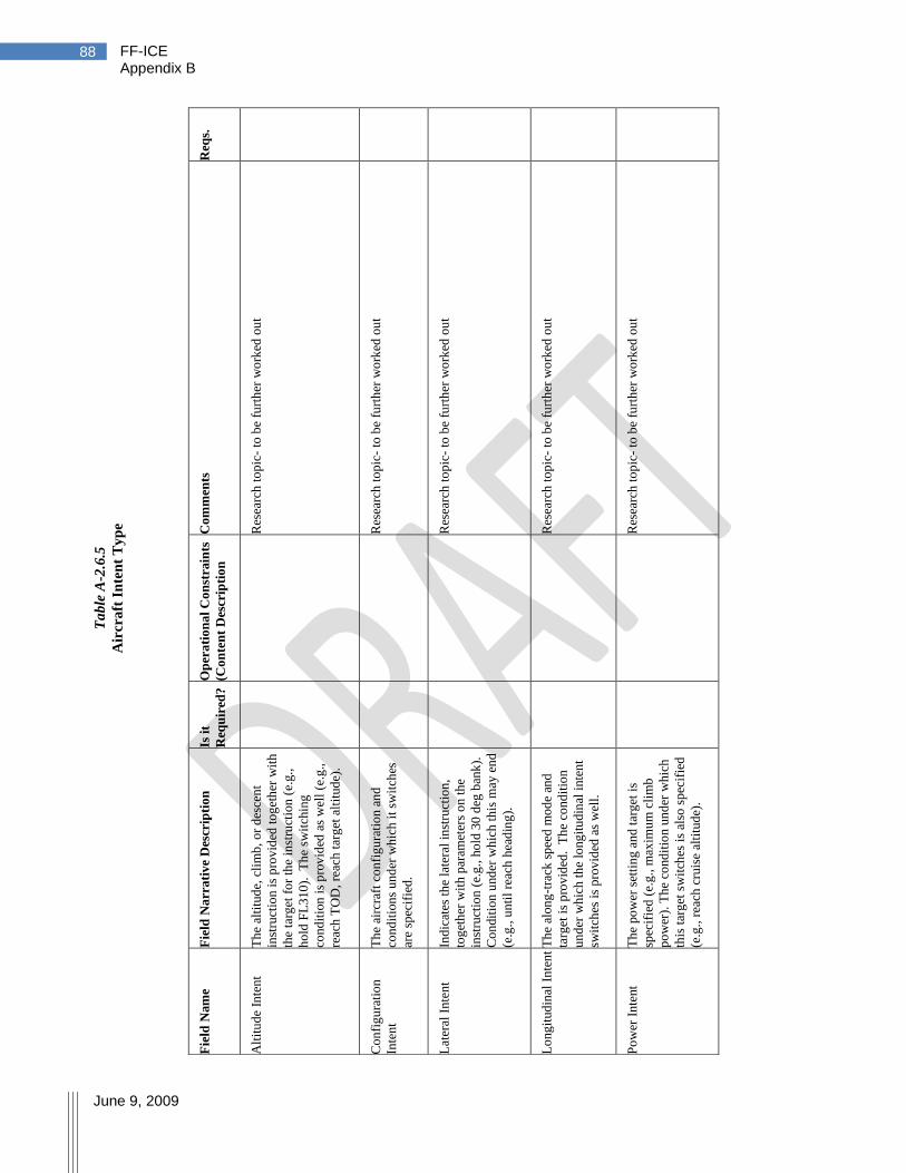
FF-ICE Appendix B
June 9, 2009
88
Req
s.
Co
mm
ents
Res
earc
h t
op
ic-
to b
e fu
rth
er w
ork
ed o
ut
Res
earc
h t
op
ic-
to b
e fu
rth
er w
ork
ed o
ut
Res
earc
h t
op
ic-
to b
e fu
rth
er w
ork
ed o
ut
Res
earc
h t
op
ic-
to b
e fu
rth
er w
ork
ed o
ut
Res
earc
h t
op
ic-
to b
e fu
rth
er w
ork
ed o
ut
Op
era
tio
na
l C
on
stra
ints
(Co
nte
nt
Des
crip
tio
n
Is i
t
Req
uir
ed?
Fie
ld N
arr
ati
ve
Des
crip
tio
n
Th
e al
titu
de,
cli
mb
, o
r d
esce
nt
inst
ruct
ion
is
pro
vid
ed t
og
eth
er w
ith
the
targ
et f
or
the
inst
ruct
ion
(e.
g.,
ho
ld F
L3
10
). T
he
swit
chin
g
con
dit
ion
is
pro
vid
ed a
s w
ell
(e.g
.,
reac
h T
OD
, re
ach
tar
get
alt
itud
e).
Th
e ai
rcra
ft c
on
fig
ura
tio
n a
nd
con
dit
ion
s un
der
wh
ich
it
swit
ches
are
spec
ifie
d.
Ind
icat
es t
he
late
ral
inst
ruct
ion
,
tog
eth
er w
ith
par
amet
ers
on
th
e
inst
ruct
ion
(e.
g., h
old
30
deg
ban
k).
Co
ndit
ion
und
er w
hic
h t
his
may
en
d
(e.g
., u
nti
l re
ach
hea
din
g).
Th
e al
on
g-t
rack
sp
eed
mo
de
and
targ
et i
s p
rov
ided
. T
he
cond
itio
n
un
der
wh
ich
th
e lo
ng
itu
din
al i
nte
nt
swit
ches
is
pro
vid
ed a
s w
ell.
Th
e po
wer
set
tin
g a
nd t
arg
et i
s
spec
ifie
d (
e.g
., m
axim
um
cli
mb
po
wer
). T
he
cond
itio
n u
nd
er w
hic
h
this
tar
get
sw
itch
es i
s al
so s
pec
ifie
d
(e.g
., r
each
cru
ise
alti
tud
e).
Fie
ld N
am
e
Alt
itu
de
Inte
nt
Co
nfi
gu
rati
on
Inte
nt
Lat
eral
In
ten
t
Lo
ng
itud
inal
In
ten
t
Po
wer
In
tent
Ta
ble
A-2
.6.5
Air
cra
ft I
nte
nt
Ty
pe
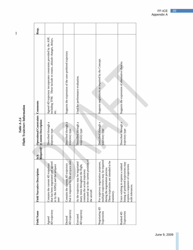
FF-ICE Appendix A
June 9, 2009
89
1 Req
s.
Co
mm
ents
Ag
reed
4D
tra
ject
ory
in
corp
ora
tes
con
stra
ints
pro
vid
ed b
y t
he
AS
P,
incl
ud
ing
TF
M.
T
hes
e in
clu
de
re-r
ou
tes,
alt
itu
de
chan
ges
, d
elay
s,
etc.
Su
pp
ort
s th
e ex
pre
ssio
n o
f th
e u
ser-
pre
ferr
ed t
raje
cto
ry
Use
d f
or
per
form
ance
ev
alu
atio
n.
Su
pp
ort
s n
ego
tiat
ion
as
requ
ired
by
th
e C
on
cep
t.
Su
pp
ort
s th
e ex
pre
ssio
n o
f al
tern
ativ
e ch
oic
es.
Op
era
tio
na
l C
on
stra
ints
(Co
nte
nt
Des
crip
tio
n
Des
crib
ed t
hro
ugh
a
traj
ecto
ry t
yp
e
Des
crib
ed t
hro
ugh
a
traj
ecto
ry t
yp
e
Des
crib
ed t
hro
ugh
a
traj
ecto
ry t
yp
e
Des
crib
ed t
hro
ugh
a
traj
ecto
ry t
yp
e
Des
crib
ed t
hro
ugh
a
traj
ecto
ry t
yp
e
Is i
t
Req
uir
ed?
Fie
ld N
arr
ati
ve
Des
crip
tio
n
Co
nta
ins
the
curr
ent
4D
tra
ject
ory
that
has
bee
n n
ego
tiat
ed a
nd
ag
reed
to b
y t
he
AS
P(s
) an
d t
he
airs
pac
e
use
r
Co
nta
ins
the
curr
ent
4D
tra
ject
ory
that
is
requ
este
d b
y t
he
airs
pac
e use
r.
As
the
traj
ecto
ry m
ay b
e n
ego
tiat
ed
man
y t
imes
th
roug
ho
ut
the
flig
ht,
con
tain
s th
e ac
tual
tra
ject
ory
exec
ute
d u
p t
o t
he
curr
ent
po
siti
on
of
the
airc
raft
Fo
r tr
ajec
tory
neg
oti
atio
n p
urp
ose
s,
mu
ltip
le t
raje
cto
ries
may
be
requ
ired
du
rin
g t
he
neg
oti
atio
n p
roce
ss.
Th
ese
traj
ecto
ries
are
in
ten
ded
to
be
tran
sito
ry.
Use
rs w
ish
ing
to
exp
ress
a r
ank
ed
list
ing o
f p
refe
rred
tra
ject
ori
es m
ay
exp
ress
a s
equ
ence
of
traj
ecto
ries
wit
h t
ole
ran
ces.
Fie
ld N
am
e
Ag
reed
4D
tra
ject
ory
Des
ired
4D
tra
ject
ory
Ex
ecu
ted
4D
tra
ject
ory
Neg
oti
atin
g 4
D
Tra
ject
ori
es
Ran
ked
4D
Tra
ject
ori
es
Ta
ble
A-2
.6
Fli
gh
t T
raje
cto
ry I
nfo
rma
tio
n
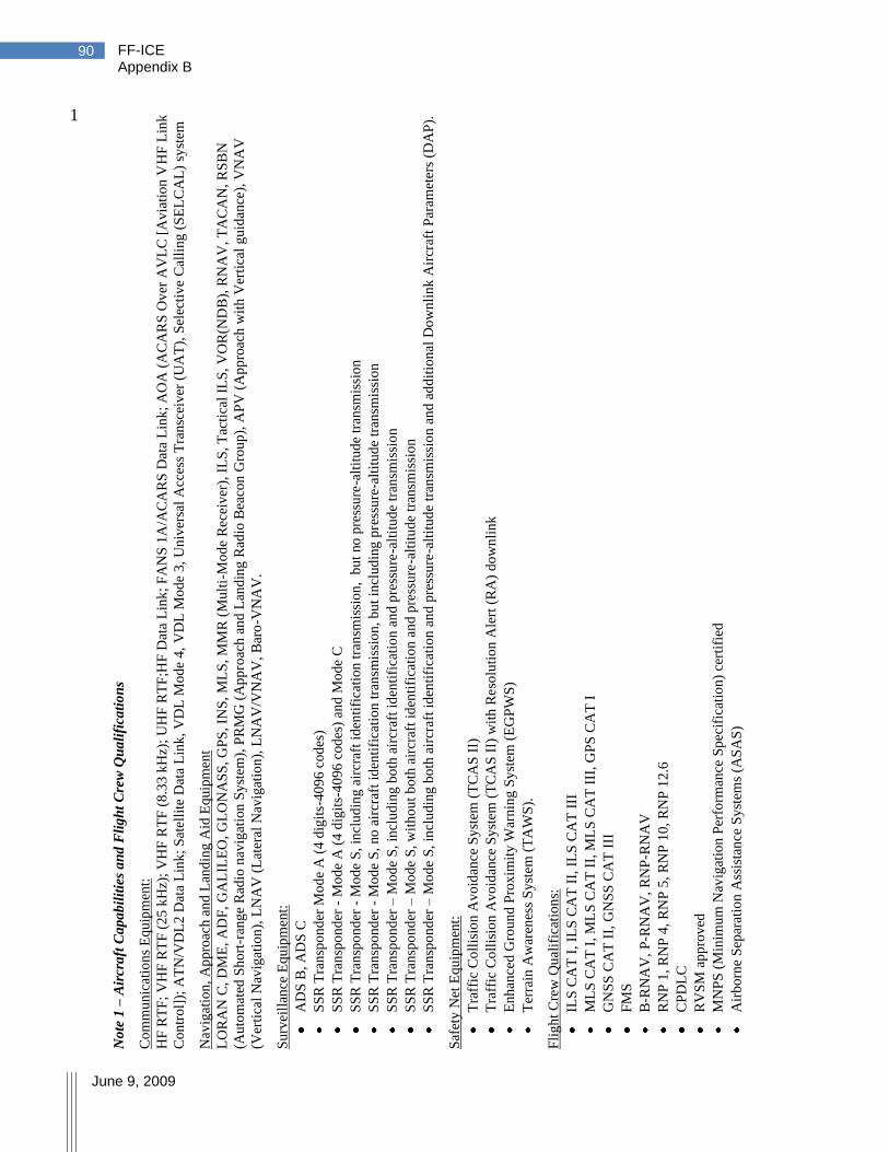
FF-ICE Appendix B
June 9, 2009
90
1 N
ote
1 –
Air
cra
ft C
ap
ab
ilit
ies
an
d F
lig
ht
Cre
w Q
ua
lifi
cati
on
s
Co
mm
un
icat
ion
s E
qu
ipm
ent:
HF
RT
F;
VH
F R
TF
(2
5 k
Hz)
; V
HF
RT
F (
8.3
3 k
Hz)
; U
HF
RT
F;H
F D
ata
Lin
k;
FA
NS
1A
/AC
AR
S D
ata
Lin
k;
AO
A (
AC
AR
S O
ver
AV
LC
[A
via
tio
n V
HF
Lin
k
Co
ntr
ol]
); A
TN
/VD
L2
Dat
a L
ink
; S
atel
lite
Dat
a L
ink
, V
DL
Mo
de
4,
VD
L M
od
e 3,
Un
iver
sal
Acc
ess
Tra
nsc
eiv
er (
UA
T),
Sel
ecti
ve
Cal
lin
g (
SE
LC
AL
) sy
stem
Nav
igat
ion
, A
ppro
ach a
nd
Lan
din
g A
id E
qu
ipm
ent
LO
RA
N C
, D
ME
, A
DF
, G
AL
ILE
O,
GL
ON
AS
S,
GP
S,
INS
, M
LS
, M
MR
(M
ult
i-M
od
e R
ecei
ver
), I
LS
, T
acti
cal
ILS
, V
OR
(ND
B),
RN
AV
, T
AC
AN
, R
SB
N
(Au
tom
ated
Sh
ort
-ran
ge
Rad
io n
avig
atio
n S
yst
em),
PR
MG
(A
pp
roac
h a
nd L
and
ing
Rad
io B
eaco
n G
rou
p),
AP
V (
Ap
pro
ach
wit
h V
erti
cal
gu
idan
ce),
VN
AV
(Ver
tica
l N
avig
atio
n),
LN
AV
(L
ater
al N
avig
atio
n),
LN
AV
/VN
AV
, B
aro
-VN
AV
.
Su
rvei
llan
ce E
qu
ipm
ent:
AD
S B
, A
DS
C
SS
R T
ran
spo
nd
er M
od
e A
(4
dig
its-
40
96
co
des
)
SS
R T
ran
spo
nd
er -
Mo
de
A (
4 d
igit
s-4
096
cod
es)
and
Mo
de
C
SS
R T
ran
spo
nd
er -
Mo
de
S,
incl
ud
ing a
ircr
aft
iden
tifi
cati
on t
ran
smis
sio
n,
bu
t no
pre
ssu
re-a
ltit
ud
e tr
ansm
issi
on
SS
R T
ran
spo
nd
er -
Mo
de
S,
no
air
craf
t id
enti
fica
tio
n t
ran
smis
sio
n,
bu
t in
clu
din
g p
ress
ure
-alt
itu
de
tran
smis
sio
n
SS
R T
ran
spo
nd
er –
Mo
de
S,
incl
ud
ing b
oth
air
craf
t id
enti
fica
tio
n a
nd
pre
ssu
re-a
ltit
ud
e tr
ansm
issi
on
SS
R T
ran
spo
nd
er –
Mo
de
S, w
ith
ou
t b
oth
air
craf
t id
enti
fica
tio
n a
nd
pre
ssu
re-a
ltit
ud
e tr
ansm
issi
on
SS
R T
ran
spo
nd
er –
Mo
de
S,
incl
ud
ing b
oth
air
craf
t id
enti
fica
tio
n a
nd
pre
ssu
re-a
ltit
ud
e tr
ansm
issi
on
an
d a
dd
itio
nal
Do
wn
lin
k A
ircr
aft
Par
amet
ers
(DA
P).
Saf
ety
Net
Eq
uip
men
t:
Tra
ffic
Co
llis
ion
Av
oid
ance
Sy
stem
(T
CA
S I
I)
Tra
ffic
Co
llis
ion
Av
oid
ance
Sy
stem
(T
CA
S I
I) w
ith
Reso
luti
on
Ale
rt (
RA
) d
ow
nli
nk
En
han
ced G
roun
d P
rox
imit
y W
arn
ing
Sy
stem
(E
GP
WS
)
Ter
rain
Aw
aren
ess
Sy
stem
(T
AW
S).
Fli
gh
t C
rew
Qu
alif
icat
ion
s:
ILS
CA
T I
, IL
S C
AT
II,
IL
S C
AT
III
ML
S C
AT
I,
ML
S C
AT
II,
ML
S C
AT
III
, G
PS
CA
T I
GN
SS
CA
T I
I, G
NS
S C
AT
III
FM
S
B-R
NA
V,
P-R
NA
V,
RN
P-R
NA
V
RN
P 1
, R
NP
4,
RN
P 5
, R
NP
10
, R
NP
12
.6
CP
DL
C
RV
SM
ap
pro
ved
MN
PS
(M
inim
um
Nav
igat
ion
Per
form
ance
Sp
ecif
icat
ion
) ce
rtif
ied
Air
bo
rne
Sep
arat
ion
Ass
ista
nce
Sy
stem
s (A
SA
S)

FF-ICE Appendix A
June 9, 2009
91
N
ote
2 –
Fli
gh
t S
tatu
s In
form
ati
on
(T
he
info
rmat
ion
des
crib
ed b
elo
w m
ay b
e d
iffe
ren
t in
th
e fu
ture
.)
flig
ht
eng
aged
in
SA
R m
issi
on
med
ical
fli
gh
t sp
ecif
ical
ly d
ecla
red
by
th
e m
edic
al a
uth
ori
ties
flig
ht
op
erat
ing
fo
r hu
man
itar
ian
rea
son
s
flig
ht
carr
yin
g a
Hea
d o
f S
tate
flig
ht
carr
yin
g S
tate
off
icia
ls o
ther
th
an a
Hea
d o
f S
tate
flig
ht
non
-co
mp
lian
t w
ith
RV
SM
req
uir
emen
ts t
hat
in
tend
s to
op
erat
e w
ith
in R
VS
M a
irsp
ace
flig
ht
spec
ific
ally
au
tho
rize
d b
y t
he
app
ropri
ate
auth
ori
ty t
o b
e ex
emp
ted
fro
m A
TF
M m
easu
res
flig
ht
for
wh
ich
th
e d
etai
ls s
ho
uld
on
ly b
e av
aila
ble
to
a r
estr
icte
d a
ud
ien
ce,
e.g
., a
sec
uri
ty s
ensi
tiv
e fl
igh
t
flig
ht
carr
yin
g h
azar
dou
s m
ater
ials
flig
ht
for
wh
ich
mil
itar
y a
ssum
es s
epar
atio
n r
esp
on
sib
ilit
ies
flig
ht
use
d f
or
po
lice
or
cust
om
s se
rvic
es

FF-ICE Appendix B
June 9, 2009
92
Appendix B. Operational Transition
This appendix contains additional detail on proposed steps for transition to the Flight and Flow 1
Information for a Collaborative Environment (FF-ICE). Scenarios are subsequently described 2
indicating the type of information exchanges that may occur in a mixed environment. 3
B.1 Transition Steps 4
In order to gain the maximum benefit of the transition steps as they are implemented, regions 5
may be advised to follow a common transition plan. A logical transition sequence may be: 6
Step 1: Submission, Retrieval and Dissemination of the FF-ICE 7
The FF-ICE concept includes a high-level description for submission, retrieval, and 8
dissemination of FF-ICE information by means of publish/subscribe and request/reply 9
mechanisms supported by System Wide Information Management (SWIM) architecture. 10
Initially it could support the flight plan (FPL) format and content, but transmitted through 11
publish/subscribe and request/reply mechanisms. This may then support the FF-ICE 12
information format and content as it becomes available. This architecture could facilitate 13
the later steps by providing a ‗converter‘ function between the FPL and FF-ICE information 14
format and content. However, it is recognized that SWIM architecture may be implemented 15
at different times and even following different technical specifications in different regions, 16
depending on local industries and requirements. 17
In an initial implementation, these advanced mechanisms may be simulated on the top of 18
existing communications infrastructure (e.g., an addressing scheme based on identification 19
of intersected airspace volumes could be adapted to simulate a publish/subscribe 20
mechanism). However, functionally, such an initial implementation would appear to the 21
participants involved as a SWIM implementation, possibly with certain technical limitations. 22
As soon as two or more regions have implemented (or simulated) a SWIM architecture, the 23
participants in those regions will be able to use it to share information, even if the internal 24
SWIM implementations may have some technical differences. 25
This is illustrated at a high level in Figure B.1-1. 26

FF-ICE Appendix A
June 9, 2009
93
Figure B.1-1
Connection between heterogeneous SWIM Regions
In Figure B.1-1, the flight data interests of SWIM Region 1 are represented in SWIM 1
Region 2 by the region 2 adaptor. For example, for a publish/subscribe interaction the 2
region 2 adaptor subscribes to all information in SWIM Region 2 which is of interest to the 3
participants accessing through SWIM Region 1. This subscription is initiated in SWIM 4
Region 1 through the region 1 adaptor requesting a subscription of the region 2 adaptor. 5
When information is published in SWIM Region 2 which is of interest to one or more 6
participants in SWIM Region 1, the region 2 adaptor receives this information, and passes it 7
through the interface. The region 1 adaptor then publishes it within SWIM Region 1, so that 8
it becomes available to any participants who have subscribed to it. 9
The example provided can be extended to other interactions (e.g., request/reply) beyond 10
publish/subscribe. This high-level mechanism can also be adapted and extended to link any 11
number of SWIM Regions together so that for the users they appear to be one unified SWIM 12
area. 13
Specifications will be needed for the interface in order to ensure the required level of 14
interoperability. An end-to-end delivery assurance scheme will be required, consistent with 15
the level of criticality of applications using the provided data. 16
Step 2: Globally Unique Flight Identifier (GUFI) 17
In some regions where there is not yet any concept of a regional unique identifier for each 18
flight, the introduction of the GUFI may require substantial system changes. However, 19
other regions may already have implemented a regional unique identifier for each flight, 20
even though it is not yet guaranteed to be globally unique. A relatively simple evolution for 21
SWIM Region 1
SWIM Region 2
Interface
SWIM
Region 2
Adaptor
SWIM
Region 1
Adaptor
Region 1
Region 2

FF-ICE Appendix B
June 9, 2009
94
the latter regions might therefore be to extend the current local identifier so that it becomes 1
globally unique (a GUFI) according to the specification which will be provided by ICAO. 2
As soon as two regions have implemented the GUFI, the ASPs and other FF-ICE 3
information users in those regions will be able to include it in any flight data which they 4
may pass to each other concerning flights which fly through both regions. 5
In this step, even flight information entering the ATM System as an FPL would receive a 6
GUFI generated according to an ICAO specification when accepted by the ATM network. 7
The GUFI would be used in any further information sharing concerning the flights. 8
Step 3: Provision and sharing of full FF-ICE Information including 4D trajectory 9
A key need of the FF-ICE concept is that 4D trajectory information and other data not 10
currently defined for the FPL be shared and synchronized between airspace user systems 11
(including on-board systems) and ATM Systems in order to facilitate several advanced 12
functions such as those required for Separation Management. The information may include 13
constraints or preferences of the airspace user or the ASP, which may be static or dynamic, 14
and may be shared in order to facilitate the trajectory negotiation process at any stage of the 15
lifecycle of the flight. 16
Each region may decide to implement sharing this advanced information between systems in 17
the region in several steps. For instance, in some regions it may be decided first to 18
implement sharing between ASP systems and later extend this to airspace user systems. In 19
other regions, sharing with airspace user systems may be given the priority. For example, 20
this would be the ‗preferred‘4D trajectory in the initial submission but would become the 21
‗agreed‘ 4D trajectory after the negotiation process. Later steps could add several instances 22
of the 4D trajectory, as defined in Appendix E, and other information such as constraints and 23
preferences according to an ICAO specification. 24
As soon as two regions have implemented a common subset of the FF-ICE Information, the 25
ASPs will be able to share it for any flights which may pass through both regions. 26
Step 4: Provision by Airspace Users of early FF-ICE Submissions 27
In most regions, strategic traffic forecasting is currently done on the basis of historical data 28
(using the traffic on a similar day from the year before as a basis), sometimes enhanced with 29
expected regional traffic growth and information about special events. 30
Before the start of each season, most airspace users who operate according to a published 31
schedule already provide their schedule in an electronic form which may be convertible into 32
the FF-ICE initial information. In a first transition step, the conversion could be performed 33
by special developments of ATM Systems, but in the longer term the airspace users would 34
migrate to the FF-ICE. 35
Some ASPs who wish to make use of early submission of FF-ICE information may develop 36
a shared forecast service based on information provided in the early submissions. For 37
example, the forecast regional traffic might include a certain daily flow of traffic, n flights 38
from airport A to airport B for a certain airline X, out of a total daily traffic, between the 39
same airports of N. If the early FF-ICE information from airline X indicates that there will 40
be m flights between A and B, not n flights, then the forecast for the flow could be updated 41

FF-ICE Appendix A
June 9, 2009
95
accordingly. The service will have to take into account both regional and local factors, as 1
applicable. 2
As soon as two regions have implemented such a forecasting service based on early 3
submissions, the ASPs in those regions may decide to share FF-ICE information for any 4
flights and flows which may pass through both regions using the publish/subscribe 5
mechanisms described herein. If the GUFI has been implemented by both regions by that 6
time, then it should be included to facilitate cross-referencing. 7
B.2 Transition Scenarios 8
The anticipation that not all ASPs will transition to the FF-ICE at once will require a means for 9
flight planning to continue during this period. Some possible scenarios for dealing with this 10
transition are described below. 11
It is assumed that there is an overlap in the information required for the FF-ICE compared to the 12
present FPL as shown in Figure B.2-1. This figure expresses the most general situation. The 13
FF-ICE will contain more information than the present FPL and may exclude certain items in the 14
present FPL. However, any information that is excluded from the present FPL will be obtainable 15
from other information contained in the FF-ICE. This implies that systems in possession of 16
future flight plan information will be capable of providing all the information in the present 17
flight plan. Practically, however, the information in the FF-ICE necessary for the FPL content 18
will usually only be populated during the last 24 hours before the flight when it has been 19
provided by the airspace user. 20
Figure B.2-1
Information overlap between FF-ICE and present FPL
21
FF-ICE Information
Requirements
Present FPL
Information
Information no longer present
in FF-ICE (Can be derived
from other FF-ICE
information)

FF-ICE Appendix B
June 9, 2009
96
The interaction between aircraft operators and ASPs can potentially fall into several categories: 1
An FF-ICE-enabled ASP may require operators to provide FF-ICE information 2
An FF-ICE-enabled ASP may allow both present-day FPL filing and FF-ICE information 3
provision for some transition period. Improved service levels may be provided to 4
operators providing the FF-ICE. 5
An ASP operating with a present-day FPL may only accept the present-day FPL 6
An ASP operating with a present-day FPL may choose to accept a FF-ICE, but operate 7
internally as if an FPL was received. 8
As discussed in Section B.1, Transition Steps, the FF-ICE may be implemented in steps and 9
partial functions may have to be supported during certain transition periods. What is clear from 10
the possible combinations of ASP and aircraft operator capabilities is that transition will require 11
collaboration between the ASPs and the aircraft operators to ensure that all parties continue to be 12
compatible during transition. 13
Information flow between ASP operating present-day FPL systems will likely continue as they 14
currently do during transition to the FF-ICE. Interacting Flight Information Regions with 15
FF-ICE capabilities will be able to exchange information contained in the FF-ICE according to 16
their levels of implementations. 17
For amendments initiated in a present-day FPL region, neighboring FF-ICE regions will likely 18
have to be able to incorporate changes to the FPL data items into the FF-ICE. Similarly, changes 19
initiated in an FF-ICE region can be transformed into the present-day FPL for transfer to 20
adjacent FIRs operating present-day FPL systems. 21
In the case of flight A in Figure B.2-2, changes initiated on the FF-ICE in the first FIR may 22
involve information elements that are not contained in the present-day FPL. In this case, three 23
choices are possible: 24
The first FF-ICE-enabled region provides only the present-day FPL information to the 25
next FIR. Changes to information contained only in the FF-ICE are not forwarded 26
downstream. 27
The FIR operating a present-day system may forward, but not use, information required 28
for the FF-ICE to the next FF-ICE region. 29
The FF-ICE-enabled regions bypass present-day regions and provide the information to 30
the next FF-ICE-enabled region. This may be accomplished through a variety of 31
mechanisms. 32

FF-ICE Appendix A
June 9, 2009
97
Figure B.2-2
Flights between present-day FPL and FF-ICE FIR
FF-ICE
FF-ICE Present-day
Present-day
A
B
FF-ICE Appendix C
June 9, 2009
98
Appendix C. Operational Scenarios 1
This appendix contains a collection of operational scenarios relevant to the Flight and Flow 2
Information for a Collaborative Environment (FF-ICE) concept, describing interactions between 3
various participants in the ATM System. Scenarios are organized approximately in the order a 4
flight might execute them. In addition to operational scenarios, tables are included describing 5
how information provided during the preceding scenario might be used. 6
C.1 Meeting Requirements 7
The operational scenarios described in this appendix indicate that ASPs will verify compliance 8
with requirements. This term may refer to several types of dynamic requirements imposed on a 9
flight and the information provided. 10
Syntax – Format for FF-ICE information items is expected to comply with a standard that 11
can be automatically checked for validity through automation. The approach will comply 12
with industry standards and provide flexibility through versioning. Standards will be 13
defined at a global level but accommodate regional extensions. 14
Content – Requirements may be specified regarding what information items must be 15
provided at a certain point in the time evolution of a flight. (For example, ATM System 16
performance may dictate the need for flight schedule information three months before 17
EOBT for flights operating to a specific destination airport.) 18
Performance – Constraints on required performance levels may be imposed on flights 19
based upon where/when they are operating. These constraints may be in such areas as 20
navigation (e.g., RNP level) or environmental (e.g., noise) performance. 21
Accuracy – FF-ICE information may have to be specified to a given level of accuracy 22
and reliability. 23
Access Permissions – Airspace users may require permission for access. 24
Operational constraints – Additional requirements on flight information may include 25
necessary operational constraints on a flight‘s trajectory. 26
C.2 Providing Initial Information 27
Figure C.2-1 provides a scenario for the provision and verification of initial information. It is 28
assumed that there are global requirements on the information that must be provided with initial 29
information and that these depend on how soon before EOBT the information is provided. There 30
may also be regional requirements, in addition to the global requirements, on providing 31
information. Global information requirements for early filing (months before operation) are 32
likely to require: 33
Estimated block time & date 34
Departure Aerodrome 35
Destination Aerodrome 36
Aircraft Type 37
Aircraft Operator 38

FF-ICE Appendix C
June 9, 2009
99
Flight Plan Originator 1
Type of Flight 2
Preferred 4D trajectory airborne segment including data items as required to provide the 3
level of accuracy required. 4
The requirement on the airborne segment accuracy allows ASP automation to determine the 5
distribution list for the information. The verification of the information proceeds as follows: 6
1. The initial ASP recipient of the information verifies the information against the global 7
syntax. Any regional extensions are not verified. 8
2. The initial ASP recipient verifies that the information meets global requirements for 9
information provision for the time of provision. 10
3. A globally unique flight identifier (GUFI) is assigned to the flight and provided to the 11
FOC. 12
4. The information is distributed to authorized parties who have previously indicated 13
interest in receiving this information in accordance with criteria. These parties may 14
include other ASPs, airspace providers, and aerodrome operators, among others. 15
5. Recipients of this information verify it against applicable regional requirements. These 16
requirements depend on how long before departure the information is provided and may 17
also depend on route or aerodrome. 18
6. Upon determining compliance with requirements, validity of the information is 19
confirmed and the initial information is accepted by the ASP. 20
Figure C.2-1
Verification of initial information
ASP
subscribers
ASP
Information is forw arded to ASP that are
subscribed to the information, the
subscription process is described in
technical scenarios
AU
The arrow s represent
logical data f low s; not
necessarily physical
data f low s.
AU is aw are of
information
requirements Mandatory Information
E.g., XSD Schema
Provide Initial Information
Verify Global Syntax
Other global requirements
Assign GUFI
GUFI
Publish
Regional requirementsVerify Requirements
Confirm validityAccept Initial Information
sd Interaction1

FF-ICE Appendix C
June 9, 2009
100
The above describes a scenario without rejection due to lack of compliance with requirements. 1
Should a recipient of information deem a lack of compliance with requirements, notification of 2
failure to comply is provided to the airspace user and the initial ASP. The airspace user would 3
be responsible for ensuring that an update meeting applicable requirements is provided. A GUFI 4
is not assigned when the initial submission does not meet global requirements. 5
C.3 Strategic Planning and Using Initial Information 6
Upon receipt of initial information, recipients use the information to perform functions as 7
identified in Table C.3-1. Early activities (illustrated in Figure C.3-1) include: 8
Airspace users perform mission planning (scheduling) to ensure the schedule is 9
achievable given resources. This involves updating initial schedule information to 10
consider requirements. Airspace users may self-adjust to pro-actively reduce 11
demand/capacity imbalances considering any existing restrictions (e.g., slots). Airspace 12
users collaborate with ASPs conducting airspace organization and management (ICAO 13
Document 9882 [R15]). 14
Aerodrome operators plan to ensure the demand does not exceed available surface 15
resources. This requires knowledge of demand (aerodromes, time and date) and type of 16
demand (aircraft type). If required for control, slot information may be provided. 17
ASPs use information on projected demand to determine if re-allocation of assets is 18
required to better meet the demand. This uses an initial estimate of flights including 19
times and initial 4D trajectory. 20
ASPs also use the information on projected demand to determine if changes to airspace 21
organization are required to optimize the allocation of resources to the demand. These 22
may also include the development of structured routes with required performance 23
requirements in highly constrained environments. These performance requirements are 24
imposed when the performance can help deliver additional throughput. Additional 25
performance requirements may be in place for environmental reasons. 26
Figure C.3-1
Activity diagram for strategic planning
AO
PA
SP
AU
Provide Capacity &
Aerodrome Constraints
Update
Initial
Information
Determine
Imbalances
Staffing Plans
Airspace
Organization
Incorporate
Requirements
CollaborateSelf-Adjust
Forecast
Demand
Determine
Capacity
AOM may
provide
requirements
on f lights
act Activity1
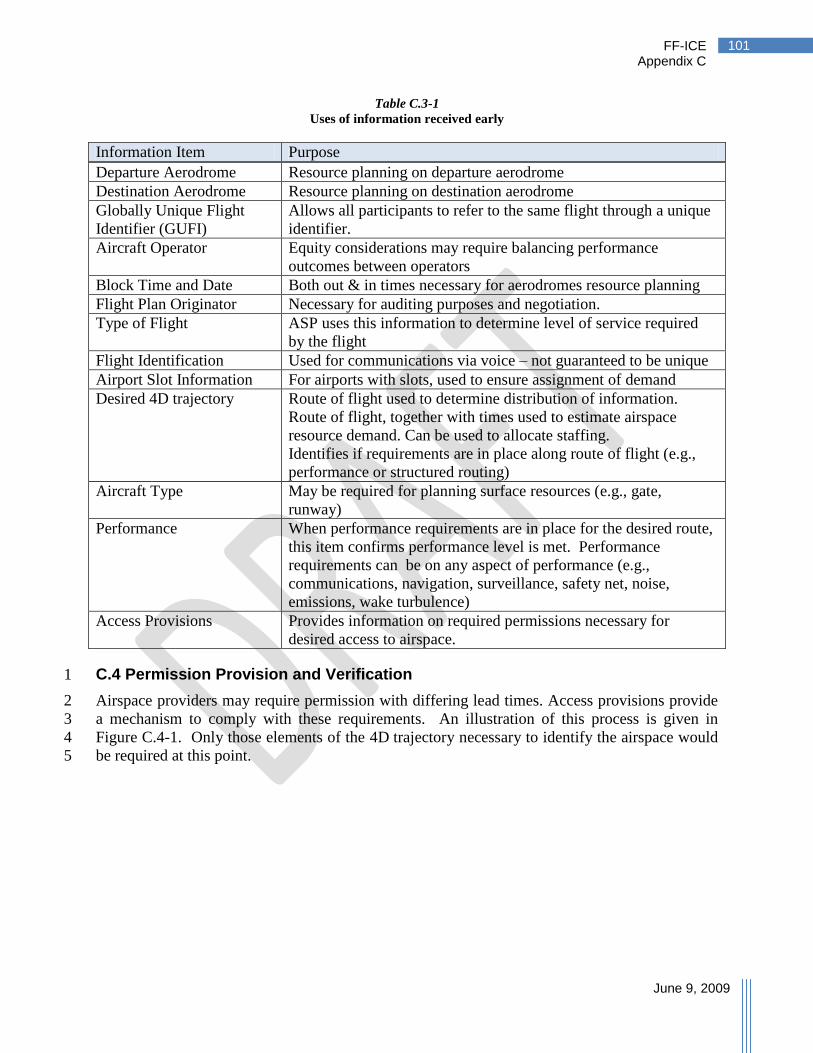
FF-ICE Appendix C
June 9, 2009
101
Table C.3-1
Uses of information received early
Information Item Purpose
Departure Aerodrome Resource planning on departure aerodrome
Destination Aerodrome Resource planning on destination aerodrome
Globally Unique Flight
Identifier (GUFI)
Allows all participants to refer to the same flight through a unique
identifier.
Aircraft Operator Equity considerations may require balancing performance
outcomes between operators
Block Time and Date Both out & in times necessary for aerodromes resource planning
Flight Plan Originator Necessary for auditing purposes and negotiation.
Type of Flight ASP uses this information to determine level of service required
by the flight
Flight Identification Used for communications via voice – not guaranteed to be unique
Airport Slot Information For airports with slots, used to ensure assignment of demand
Desired 4D trajectory Route of flight used to determine distribution of information.
Route of flight, together with times used to estimate airspace
resource demand. Can be used to allocate staffing.
Identifies if requirements are in place along route of flight (e.g.,
performance or structured routing)
Aircraft Type May be required for planning surface resources (e.g., gate,
runway)
Performance When performance requirements are in place for the desired route,
this item confirms performance level is met. Performance
requirements can be on any aspect of performance (e.g.,
communications, navigation, surveillance, safety net, noise,
emissions, wake turbulence)
Access Provisions Provides information on required permissions necessary for
desired access to airspace.
C.4 Permission Provision and Verification 1
Airspace providers may require permission with differing lead times. Access provisions provide 2
a mechanism to comply with these requirements. An illustration of this process is given in 3
Figure C.4-1. Only those elements of the 4D trajectory necessary to identify the airspace would 4
be required at this point. 5

FF-ICE Appendix C
June 9, 2009
102
Figure C.4-1
Illustration of a candidate sequence for permission provision and verification
C.5 Providing Additional Information Prior to Departure Day 1
Before the day of departure, activities are conducted by all participants to improve the 2
performance of the ATM System, given the level of requested demand. There is a refinement 3
and continuation of previously described activities as greater certainty of information is achieved 4
and airspace users with various planning horizons provide more information. At this stage, some 5
of these activities include: 6
Airspace structures and performance levels may be required to accommodate demand. 7
These can provide requirements for flights to use structured routes in constrained 8
airspace, or may require a level of performance to operate within airspace. 9
Airspace users consider the operational constraints provided to them, and update their 10
plans in accordance with required constraints. 11
Airspace users begin to provide preference information on the flight; some of this is 12
provided through the desired 4D trajectory and a ranked list of alternatives. Other 13
preferences are provided through specific preference information items (e.g., priority). 14
Figure C.5 illustrates a candidate sequence for some of the above activities. The sequence 15
diagram describes the interaction between the airspace user planning participant (e.g., the flight 16
operations center) and the ASP. Interactions within the ASP are not described. While the 17
process appears highly repetitive, the update is not likely to be triggered through receipt of single 18
flight information. In practice, the imposition of structure and performance requirements will 19
also include some element of anticipated demand in the early stages, before demand being 20
known accurately. Airspace users will adjust flights through the optimal assignment of their 21
high performing flights and through adjustment of the 4D trajectory. 22
ASP ASP (n)AU Airspace
Provider
The arrow s represent
logical data f low s; not
necessarily physical
data f low s.
ASP associated
w ith AP
Part of local
requirements
get permissions
Permissions
Permissions & 4DT
Permissions & 4DTEnsure valid Permissions
Confirm validity
Accept
sd Interaction2

FF-ICE Appendix C
June 9, 2009
103
Figure C.5
Illustration of imposition of airspace structure or performance requirements to deal with expected
imbalances
Figure C.5 describes a process after the initial FF-ICE information has been supplied for a flight 1
and for many flights scheduled to operate on the same day. The process described in Figure C.5 2
is summarized below. 3
1. The aerodrome operator provides aerodrome capacity and any aerodrome constraints. 4
2. When necessary, the airspace user may update the FF-ICE information provided earlier; 5
for example, the airspace user may supply an updated 4D trajectory. 6
3. Upon submission of new information, the receiving ASP will verify compliance with 7
applicable requirements. 8
4. The airspace user is notified of compliance with requirements. 9
5. The ASP uses the new information to update the demand being used for DCB. 10
ASPAU
Service may include
identif ication of f lights
subject to imbalances
Service may include
evaluation of f lights for
compliance
The arrow s represent
logical data f low s; not
necessarily physical
data f low s.
AOPInitial information
is available
Collaboration expected
An ongoing process
4DT
Update Demand
Determine Imbalances
Require Performance/structure
Share requirements
Adjust f lights
Update
Verify requirement compliance
Notify compliance
Aerodrome Capacity & constraints
Feedback
Identif ied Flights
Evaluation request
Evaluation reply
Evaluate
sd Interaction3

FF-ICE Appendix C
June 9, 2009
104
6. The ongoing DCB process continues to operate using the updated information and may 1
identify a capacity imbalance as a result of the new information. 2
7. There may be a service provided by the ASP allowing airspace users to be notified when 3
flights are projected to create a demand/capacity imbalance. 4
8. The ongoing airspace organization and management (AOM) processes may require 5
airspace structure or performance requirements to accommodate large demand. These 6
requirements are developed through a collaborative process. 7
9. In response to additional requirements on performance or structure, the airspace users 8
will adjust their flights to comply. This may involve the use of information services 9
provided by the ASP; the ASP may provide a service verifying compliance with 10
specified requirements. 11
10. The airspace user will provide updates to the flight information. 12
C.6 Departure Day Activities 13
On the day of departure, weather and wind information is more certain, this allows planning to 14
begin to consider the capacity degrading effects of weather and the effect of winds on 15
trajectories. 16
17

FF-ICE Appendix C
June 9, 2009
105
Table C.6
Uses of Additional Information Items on Day of Departure
Information Items Purpose
SAR Information Search and rescue information is required pre-departure to expedite search
and rescue efforts if this becomes necessary. Type of Flight Required pre-departure for proper application of rules and service level 24 Bit Aircraft Address Allows correlation of flight information with surveillance information Type of Aircraft Used for estimating effect on runway demand when wake performance is
not supplied separately. Used for applying appropriate separation standards when wake performance
is not supplied. Wake Turbulence Performance Used for applying wake separation. Communications, Navigation,
Surveillance or Safety Net
Performance
If requirements are specified for access to a resource, service, or service
level, indicates the level of aircraft performance.
Noise/ Emissions Performance Where requirements are in place for access based upon level of noise or
emissions performance, informs that access can be granted to this flight
(subject to mechanisms for verification of compliance). Applications and Approvals Where access to a service, resource or procedure is governed by functioning
on-board applications or equipment and approval to operate; this item
informs the ASP that the flight can be granted access. Flight Status Flights with certain status may be subject to differing requirements on
access, priority or level of service. Informs the ATM System of the status
so the appropriate requirements can be applied. Preferences Information Information on airspace user preferences can be provided to allow the ASP
to select from options that best meet provided preferences. This is a form
of collaboration that expedites the selection of a solution. Preferences
include such information as: priority within a fleet for sequencing,
maximum delay for selection of a runway over another, operating practices
limiting the choices that are not acceptable to the airspace user, and
movement preferences indicating preferred trajectory changes. Desired 4D trajectory This provides the trajectory that is generated by the airspace user best suited
to meet their mission objectives. This trajectory is generated with
knowledge, by the airspace user, of required operational constraints and
resource contention. The user may elect to preemptively circumvent
resource contention or engage in collaboration on the trajectory. Agreed 4D Trajectory This expresses the 4D trajectory that is agreed to between the airspace user
and the ASPs after collaboration or imposition of pre-collaborated rules. Executed 4D trajectory This maintains the trajectory that is flown by the airspace user up to the
present position. As changes to the trajectory may occur along the flight,
this maintains a record suitable for performance analysis. Negotiating 4D trajectory This trajectory is used during collaboration to agree on a 4D trajectory.
More information on the use of this information is described in section C.7. Ranked 4D trajectory This provides a data structure with ranked trajectory preferences.
Tolerances are used to express the bounds of variation on the trajectory
triggering a preference for the next ranked trajectory. This data structure
facilitates the collaborative process.

FF-ICE Appendix C
June 9, 2009
106
C.6.1 Provide Desired 4D trajectory 1
Providing the desired 4D trajectory is a straightforward process similar to providing initial 2
information. The process immediately preceding the provision is illustrated in Figure C.6-1. 3
1. When providing the desired 4D trajectory, the airspace user has access to shared weather 4
and wind information. 5
2. Airspace requirements providing access restrictions or required routing structures are also 6
shared with the airspace user. 7
3. If performance requirements are necessary for access due to capacity or environmental 8
limitations, these are shared with the airspace user as well. 9
4. Projected capacity imbalances are known to the airspace user. 10
5. The airspace user uses the above information in generating a desired 4D trajectory. The 11
airspace user can allocate resources to flights to develop a desired 4D trajectory consistent with 12
known requirements and internal objectives. Where necessary, this trajectory indicates 13
compliance with airspace structure and performance requirements. Compliance with airspace 14
structure is indicated by referencing the constituent route in the 4D trajectory. The performance 15
of the combined airframe and crew on the required trajectory elements is indicated though the 16
performance item in the 4D trajectory airborne elements. 17
6. The airspace user updates the FF-ICE with the desired 4D trajectory. 18
7. This information is used by the ASP to verify compliance with airspace and performance 19
requirements. Flight status information is used by the ASP to determine which requirements are 20
applicable. 21
8. The airspace user is notified of compliance (or lack thereof) with requirements. Lack of 22
compliance with requirements may not result in rejection of the information, but may result in 23
the flight not receiving a clearance. 24

FF-ICE Appendix C
June 9, 2009
107
Figure C.6-1
Provision of desired 4D trajectory
C.6.2 Obtain Agreed 4D trajectory 1
For a flight desiring to operate along a congested trajectory, allocation of resources must occur. 2
One initial mechanism to mitigate this involves the airspace user altering the desired 3
4D trajectory such that it is no longer subject to predicted congestion. This can be accomplished 4
through the ASP sharing information on predicted areas of congestion (e.g., projected 5
imbalances in Figure C.6-1) or providing a service evaluating options against predicted 6
congestion. Reaching an agreed 4D trajectory when the airspace user has met all requirements 7
and mitigated imbalances represents a trivial case where agreement is simply acknowledged. 8
However, there are times when this mechanism is insufficient to balance demand and capacity. 9
It is assumed that a set of unambiguous pre-collaborated rules among participants establishes a 10
mechanism by which these situations are arbitrated. There may be regional variations in these 11
mechanisms. Part of the collaboration must include collaboration between ASPs to ensure 12
seamlessness and interoperability. Given knowledge of the rules, the airspace user may elect to 13
alter the desired 4D trajectory to provide the optimal performance outcome subsequent to the 14
application of the rules. 15
16
ASPAU
Where required, includes
performance information,
and reference to airspace
structures
AU is aw are of projected
imbalances and
consequences
ASP:Wx The arrow s represent
logical data f low s; not
necessarily physical
data f low s.
At some point, lack
of compliance
triggers rejection
Requirements may
not all be dynamic
Weather/w inds
Airspace Requirements
Performance Requirements
4DT generation
Desired 4DT
Verify Compliance
Projected Imbalances
Notify
Update Requirements
sd Interaction4
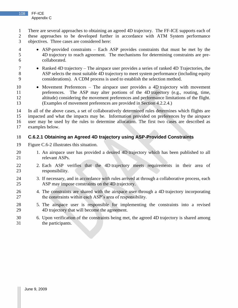
FF-ICE Appendix C
June 9, 2009
108
There are several approaches to obtaining an agreed 4D trajectory. The FF-ICE supports each of 1
these approaches to be developed further in accordance with ATM System performance 2
objectives. Three cases are considered here: 3
ASP-provided constraints – Each ASP provides constraints that must be met by the 4
4D trajectory to reach agreement. The mechanisms for determining constraints are pre-5
collaborated. 6
Ranked 4D trajectory – The airspace user provides a series of ranked 4D Trajectories, the 7
ASP selects the most suitable 4D trajectory to meet system performance (including equity 8
considerations). A CDM process is used to establish the selection method. 9
Movement Preferences – The airspace user provides a 4D trajectory with movement 10
preferences. The ASP may alter portions of the 4D trajectory (e.g., routing, time, 11
altitude) considering the movement preferences and performance limitations of the flight. 12
(Examples of movement preferences are provided in Section 4.2.2.4.) 13
In all of the above cases, a set of collaboratively determined rules determines which flights are 14
impacted and what the impacts may be. Information provided on preferences by the airspace 15
user may be used by the rules to determine allocation. The first two cases are described as 16
examples below. 17
C.6.2.1 Obtaining an Agreed 4D trajectory using ASP-Provided Constraints 18
Figure C.6-2 illustrates this situation. 19
1. An airspace user has provided a desired 4D trajectory which has been published to all 20
relevant ASPs. 21
2. Each ASP verifies that the 4D trajectory meets requirements in their area of 22
responsibility. 23
3. If necessary, and in accordance with rules arrived at through a collaborative process, each 24
ASP may impose constraints on the 4D trajectory. 25
4. The constraints are shared with the airspace user through a 4D trajectory incorporating 26
the constraints within each ASP‘s area of responsibility. 27
5. The airspace user is responsible for implementing the constraints into a revised 28
4D trajectory that will become the agreement. 29
6. Upon verification of the constraints being met, the agreed 4D trajectory is shared among 30
the participants. 31

FF-ICE Appendix C
June 9, 2009
109
Figure C.6-2
Determining Agreed 4D trajectory using constraints
C.6.2.2 Using Ranked 4D trajectory to obtain an Agreed 4D trajectory 1
The airspace user may provide the ASP with a series of ranked 4D Trajectories with tolerances 2
indicating preferences. For example, as shown in Figure C.6-3, one trajectory may represent one 3
routing with a tolerance on delay to accept the trajectory. If the 4D trajectory cannot be 4
accommodated within the delay tolerance, the next ranked trajectory would be preferred. This 5
process can continue for multiple ranked 4D Trajectories. The ASP would apply (pre-6
collaborated) rules to assign the choices to the flights as illustrated in Figure C.6-4. The 7
selection of one of the ranked 4D Trajectories would result in a negotiating 4D trajectory. This 8
would alter the trajectory within the original tolerances and propose a set of tolerances within 9
which the flight must operate. If this is acceptable to the airspace user, the negotiating 10
4D trajectory becomes the agreed 4D trajectory. 11
ASP-2ASP-1AU
The arrow s represent
logical data f low s; not
necessarily physical
data f low s.
Only verify
portion of 4DT
in ASP airspace
Share
end-to-end
agreeement
Verify 4DT in
ow n airspace
4DT Publish
Verify 4DT
Constrained 4DT
Verify 4DT
Constrained 4DT
Constrained 4DT
Agreed to 4DT
Implement Constraints
Publish
Impose Constraints
Impose Constraints
Determine suitability
sd Interaction9

FF-ICE Appendix C
June 9, 2009
110
Figure C.6-3
Illustration of ranked 4D trajectory
Figure C.6-4
Selection of ranked 4D trajectory
1
ASPAU
ASP selects from ranked 4DTs
betw een flights to meet resource
constraints in accordance w ith
pe-coordinated rules
The arrow s represent
logical data f low s; not
necessarily physical
data f low s.
Ranked 4DT
Assign 4DT
Negotiating 4DT
Agreed-to 4DT
Verify Compliance
Evaluate all know n flights against constraints
Verify suitability
sd Interaction5
ADEP
ADES
Preferred 4DT with
max deviation
tolerance
Second
choice 4DT
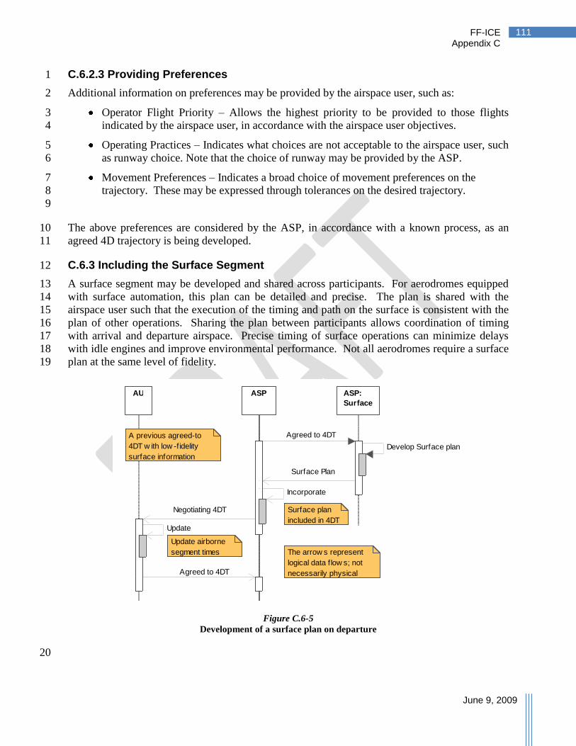
FF-ICE Appendix C
June 9, 2009
111
C.6.2.3 Providing Preferences 1
Additional information on preferences may be provided by the airspace user, such as: 2
Operator Flight Priority – Allows the highest priority to be provided to those flights 3
indicated by the airspace user, in accordance with the airspace user objectives. 4
Operating Practices – Indicates what choices are not acceptable to the airspace user, such 5
as runway choice. Note that the choice of runway may be provided by the ASP. 6
Movement Preferences – Indicates a broad choice of movement preferences on the 7
trajectory. These may be expressed through tolerances on the desired trajectory. 8
9
The above preferences are considered by the ASP, in accordance with a known process, as an 10
agreed 4D trajectory is being developed. 11
C.6.3 Including the Surface Segment 12
A surface segment may be developed and shared across participants. For aerodromes equipped 13
with surface automation, this plan can be detailed and precise. The plan is shared with the 14
airspace user such that the execution of the timing and path on the surface is consistent with the 15
plan of other operations. Sharing the plan between participants allows coordination of timing 16
with arrival and departure airspace. Precise timing of surface operations can minimize delays 17
with idle engines and improve environmental performance. Not all aerodromes require a surface 18
plan at the same level of fidelity. 19
Figure C.6-5
Development of a surface plan on departure
20
ASPAU ASP:
Surface
A previous agreed-to
4DT w ith low -fidelity
surface information
The arrow s represent
logical data f low s; not
necessarily physical
data f low s.
Update airborne
segment times
Surface plan
included in 4DT
Agreed to 4DT
Develop Surface plan
Surface Plan
Incorporate
Negotiating 4DT
Update
Agreed to 4DT
sd Interaction6

FF-ICE Appendix C
June 9, 2009
112
Figure C.6-5 illustrates the agreement of a surface segment. The ASP managing the FF-ICE 1
information is illustrated separately from the ASP providing surface functions. 2
1. An airspace user has previously provided a desired 4D trajectory with a departure gate 3
and time which resulted in an agreed 4D trajectory. The airborne segment starts at a 4
specific wheels-up time determined from a nominal taxi time. There is uncertainty 5
around times in the airborne segment consistent with the taxi time uncertainty. 6
Tolerances must exceed this uncertainty. 7
2. In an automated environment, surface automation develops a surface plan, within 8
tolerance times. 9
3. The surface plan is incorporated into the FF-ICE information pending approval by the 10
airspace user. 11
4. The surface plan is provided to the airspace user as a negotiating 4D trajectory. 12
5. The airspace user, with more precise knowledge of the departure time, may update the 13
airborne segment nominal times to reflect the change. The information is incorporated 14
into an updated agreed 4D trajectory. This agreed 4D trajectory is shared with the flight 15
deck (or other relevant airspace user) for execution. 16
C.6.4 Constraining a Trajectory 17
Several functions, such as traffic synchronization (TS) or strategic conflict management can 18
require the imposition of constraints along the trajectory. These include imposing control times 19
along the trajectory, altitude, speed, or lateral constraints. As shown in Figure C.6-6, a 20
previously agreed 4D trajectory, a 4D trajectory under negotiation or a desired 4D trajectory not 21
yet agreed upon may require constraints. The ASP determines the applicable constraints, 22
together with tolerances on meeting those, and provides them to the airspace user in a negotiating 23
trajectory. The airspace user considers these constraints with several outcomes: 24
The constraints can be met by the flight, with updates to the 4D trajectory reflecting the 25
new trajectory meeting the constraints. The airspace user provides the updated 26
4D trajectory as an agreed 4D trajectory to be executed by the flight. 27
Constraints are not desirable to the airspace user, resulting in the airspace user composing 28
a new alternative 4D trajectory proposal in the form of a negotiating 4D trajectory. 29
The constraints cannot be met by the flight due to aircraft performance considerations. A 30
negotiating trajectory is supplied, meeting constraints that can be met and failing to meet 31
others. How the negotiation proceeds from here remains an open question. The airspace 32
user could provide flight-specific aircraft intent and performance limits or the range of 33
feasible constraints. 34
The agreed 4D trajectory provided after the imposition of constraints and tolerances represents 35
what is referred to in the Global ATM Operational Concept as the 4D trajectory ―contract.‖ 36
When the initial set of constraints is not feasible or desirable, negotiating 4D Trajectories can be 37
exchanged as new proposals. To facilitate convergence, some additional information should be 38
provided to guide how to compose the new 4D trajectory. 39
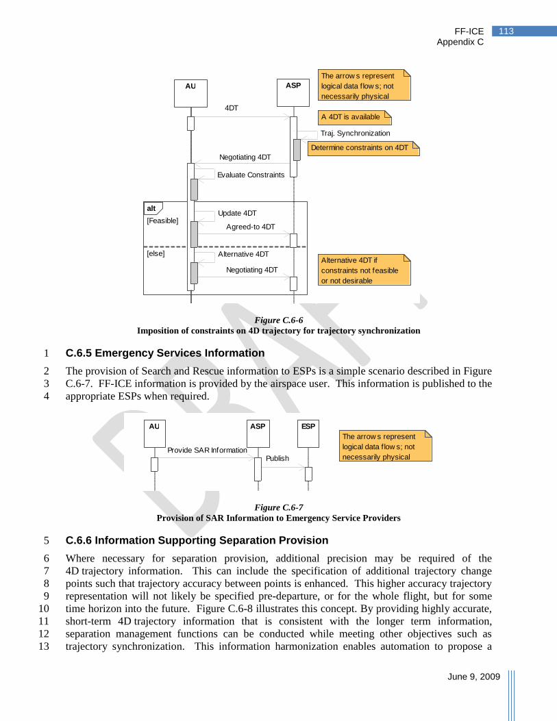
FF-ICE Appendix C
June 9, 2009
113
Figure C.6-6
Imposition of constraints on 4D trajectory for trajectory synchronization
C.6.5 Emergency Services Information 1
The provision of Search and Rescue information to ESPs is a simple scenario described in Figure 2
C.6-7. FF-ICE information is provided by the airspace user. This information is published to the 3
appropriate ESPs when required. 4
Figure C.6-7
Provision of SAR Information to Emergency Service Providers
C.6.6 Information Supporting Separation Provision 5
Where necessary for separation provision, additional precision may be required of the 6
4D trajectory information. This can include the specification of additional trajectory change 7
points such that trajectory accuracy between points is enhanced. This higher accuracy trajectory 8
representation will not likely be specified pre-departure, or for the whole flight, but for some 9
time horizon into the future. Figure C.6-8 illustrates this concept. By providing highly accurate, 10
short-term 4D trajectory information that is consistent with the longer term information, 11
separation management functions can be conducted while meeting other objectives such as 12
trajectory synchronization. This information harmonization enables automation to propose a 13
alt
[Feasible]
[else]
AU ASP
The arrow s represent
logical data f low s; not
necessarily physical
data f low s.
Alternative 4DT if
constraints not feasible
or not desirable
Determine constraints on 4DT
A 4DT is available
Traj. Synchronization
Negotiating 4DT
Evaluate Constraints
Agreed-to 4DT
Negotiating 4DT
Update 4DT
Alternative 4DT
4DT
sd Interaction7
The arrow s represent
logical data f low s; not
necessarily physical
data f low s.
ASP ESPAU
Provide SAR InformationPublish
sd Interaction18

FF-ICE Appendix C
June 9, 2009
114
single solution considering both objectives, thereby minimizing the instructions necessary to 1
achieve them. 2
Consistency of the 4D trajectory being executed by the aircraft with the 4D trajectory being used 3
to deliver ATM services is an important attribute. This allows the aircraft to control to certain 4
important constraints and deliver a level of trajectory precision for synchronization. For 5
separation provision, particularly when altitude transitions occur, more information is required to 6
obtain the level of precision required. While the precise mechanism for ensuring consistency of 7
this information is not currently determined, the interaction with the aircraft supports a case for 8
international harmonization. (As of the writing of this document, information items for this 9
higher-precision trajectory were extracted from items described in ARINC 702A-3 under 10
trajectory intent data.) 11
One mechanism for understanding the need, at times, for this higher precision information is to 12
envision what happens if the information is not available. Without use of the higher precision 13
information, the separation management function makes assumptions about the expected 14
trajectory within the agreed 4D trajectory tolerances. This may be to protect the 4D trajectory 15
with tolerances or a path predicted by the SM function within the tolerances. Without improved 16
information from current operations, the prediction will suffer from inaccuracies. The result of 17
both approaches is the need to impose large buffers on separation management to ensure aircraft 18
are separated. Large buffers increase controller workload by displacing more aircraft than 19
necessary, decrease single-flight efficiency, and increase the likelihood of downstream workload 20
resulting from missed constraints. 21
Figure C.6-8
Illustration of higher precision 4D trajectory information consistent with an Agreed 4D trajectory
22
Agreed 4DT
Higher precision
4DT information
Agreed 4DT
Higher precision
4DT Information
Within
tolerance of
agreed 4DT

FF-ICE Appendix C
June 9, 2009
115
Where precision is required, one may argue that trajectory tolerances can be tightened to ensure 1
improved precision of the agreed 4D trajectory. However, since the trajectory must remain 2
flyable, similar data structures would be required to express this constrained 4D trajectory to the 3
higher level of precision. 4
Even though a high precision 4D trajectory may be required for separation assurance, concerns 5
over interoperability require the integration of this information with the FF-ICE. By having 6
common, integrated trajectory information within the FF-ICE, separation management can seek 7
solutions that are consistent with downstream trajectory constraints, and modify any agreements 8
on the 4D trajectory where necessary. While the shorter time horizon for this high-precision 9
information would not frequently necessitate the sharing of this information across ASP, 10
consistency with the aircraft requires common information standards. 11
C.7 Negotiation Across Multiple ASPs 12
One of the objectives of the FF-ICE is to improve global interoperability. This example 13
describes the collaborative trajectory negotiation process using the FF-ICE across ASPs. Figure 14
C.7-1 describes the scenario, and a negotiation process illustrated in Figure C.7-2 is applied. 15
Figure C.7-1
Example illustrating negotiation across multiple ASP
A flight has provided a desired 4D trajectory seeking to operate through two ASPs. The 16
information has been shared with both ASP who have performed DCB and AOM functions on 17
all flights. In the case of ASP-2, the flight is required to operate on a specified arrival route with 18
a specified performance level. This information is shared through airspace information on ASP-19
2. The airspace user, aware of the restriction, modifies the flight to indicate the meeting of 20
performance and the constraint. This is accomplished through submission of a new 21
4D trajectory. As weather information becomes more certain, ASP-1 provides information of 22
constrained airspace through airspace information. The airspace user considers this information 23
and provides a new end-to-end negotiating 4D trajectory considering constraints in both ASP. 24
Both ASPs must verify the 4D trajectory for an agreed 4D trajectory to be reached. 25
ASP - 1
ASP - 2 Constraints
through
Airspace
Information
RTA Altitude
Constraint
Required route
w/ performance
User-generated
alternative

FF-ICE Appendix C
June 9, 2009
116
TS in ASP-2 requires the imposition of flight-specific constraints on arrival time (e.g., RTA) and 1
altitude entry onto the arrival route. This information is provided to the airspace user in the form 2
of constraints on a trajectory. The airspace user generates a suitable trajectory meeting those 3
constraints and provides the update to both ASP as a new negotiating trajectory. 4
One process for creating an Agreed 4D trajectory is shown in Figure C.6-2. In this case, a new 5
negotiating trajectory has been received from the airspace user by all ASPs. Each ASP verifies 6
that the proposed 4D trajectory meets requirements within their own airspace and, if so, indicates 7
acceptance of the negotiating 4D trajectory. Upon receipt of a complete end-to-end trajectory 8
agreed to by the ASP, the ASP indicates agreement on the 4D trajectory. This end-to-end 9
trajectory is shared. 10
The airspace user has the responsibility for the generation and agreement of the end-to-end 11
trajectory to try to meet the constraints of the ASPs; therefore a more feasible trajectory is 12
provided. These constraints may be the result of the application of different rules within the 13
airspace controlled by the ASPs. Since these rules may lead to infeasible multiple constraints, it 14
is important that a collaborative process be applied to develop the rules for constraint 15
application. The issue of constraint feasibility must be considered at that stage. 16
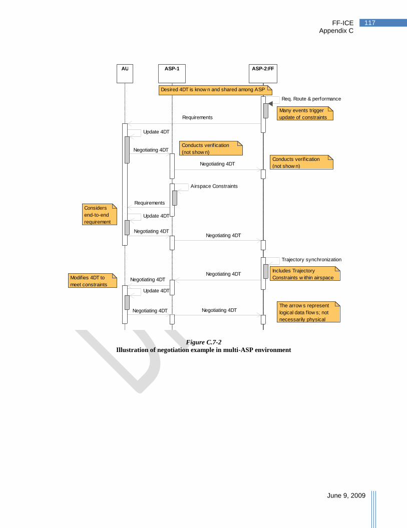
FF-ICE Appendix C
June 9, 2009
117
Figure C.7-2
Illustration of negotiation example in multi-ASP environment
ASP-2:FFASP-1AU
The arrow s represent
logical data f low s; not
necessarily physical
data f low s.
Desired 4DT is know n and shared among ASP
Includes Trajectory
Constraints w ithin airspace
Conducts verif ication
(not show n)
Conducts verif ication
(not show n)
Many events trigger
update of constraints
Considers
end-to-end
requirement
s
Modifies 4DT to
meet constraints
Update 4DT
Negotiating 4DT
Negotiating 4DT
Airspace Constraints
Requirements
Update 4DT
Negotiating 4DTNegotiating 4DT
Trajectory synchronization
Negotiating 4DTNegotiating 4DT
Update 4DT
Negotiating 4DT Negotiating 4DT
Req. Route & performance
Requirements
sd Interaction8

FF-ICE Appendix D
June 9, 2009
118
Appendix D. Understanding the Trajectory
Figure D-1
Components of the 4D trajectory
All 4D trajectories are described using the components shown in Figure D-1. A gate-to-gate 1
trajectory includes the departure aerodrome, a departure surface segment, an airborne segment, 2
and an arrival surface segment at a destination aerodrome. These segments are defined further 3
below. Additional fields include: aircraft intent, sequence number and overall performance. 4
D.1 Surface Segment 5
The departure surface segment is a generic surface segment applied to departure. As shown in 6
Figure D.1-1, the departure surface segment starts at a gate or stand, includes a block time and 7
date, a taxi path, a runway, and a runway time. Depending on the type of trajectory being 8
described, the times may be estimated or actual. The runway time represents the takeoff time for 9
a departure. An arrival surface segment uses the same data structure with items representing 10
their arrival counterparts. 11
Departure
Aerodrome
Destination
Aerodrome
Airborne Segment Departure
Surface
Segment
Arrival
Surface
Segment
Components of the 4DT:

FF-ICE Appendix D
June 9, 2009
119
Figure D.1
Illustration of a Surface Segment
The taxi path is represented through a list of taxi path elements (see Figure D.1-1). Each taxi 1
path element is represented by the following items: 2
Surface Element – Using references to aeronautical information, these can be taxiway, 3
gate, parking stands, runway, de-icing locations, aprons, or any area on the surface of the 4
airport that a flight may spend time on. 5
Surface Element Entry Time – The time at which the flight is estimated to enter the 6
surface element. 7
Type of Surface Element – Describes what type of element is being described (taxiway, 8
runway, de-icing, etc.) 9
Surface Element Speed –Describes the speed along a surface element on which the 10
aircraft is expected to be moving (optional). 11
Gate or
stand
Block time
& date
Taxi Path:
Runway
Runway time
& date
Taxi Path Element
(takeoff/landing)
Components of the
Surface Segment:

FF-ICE Appendix D
June 9, 2009
120
D.2. Airborne Segment 1
Figure D.2-1
Airborne Segment Description
Figure D.2-1 illustrates the airborne segment as viewed from the profile and plan view. The 2
airborne segment is described in terms of airborne elements. Each airborne element describes a 3
path from the last airborne element to the ―To Point 4D.‖ This point is expressed using 3D 4
location and time. The airborne element includes airspeed at a change point, and the type of 5
change point described by the ―To Point.‖ The type of change point (e.g, top-of-climb, speed 6
change) is also described. Constraints can be specified for the airborne element and are 7
applicable at the ―To Point.‖ These can be: altitude, time, speed, or lateral constraints. An 8
airborne element may require a turn descriptor; in this case, additional information is included to 9
describe the turn, together with a ―Reference Point‖ describing the point traditionally associated 10
with the route. If the flight is to follow a sequence of airborne elements that are part of a defined 11
route, the ―Constituent Route‖ will also be included. This can be useful if the route has 12
performance requirements associated with it. 13
D.2.1 Performance, Flight Rules, and Alternates 14
An airborne element may also contain information on performance, flight rules, or alternate 15
aerodromes. This information is only to be included at points where it is expected to change 16
along the trajectory. For example, a flight‘s navigation performance may be RNP-4 in oceanic 17
airspace, but may be significantly lower on final approach. The airborne element at which the 18
performance changes contains the new performance level that applies until that performance item 19
is changed at a downstream airborne element. This can also apply to flight rules; for example, if 20
the flight is expected to operate as VFR for some portion of the flight. Alternate aerodromes can 21
Airborne
Element
To Point 4D Altitude
Constraint
Airspeed
Turn
Descriptor
Reference
Point
Time
Constraint
Lateral
Constraint
Performance
Flight Rules
Alternate aerodrome

FF-ICE Appendix D
June 9, 2009
121
also be expressed along the trajectory as the designated alternate may vary along the route of 1
flight. 2
D.2.2 Aircraft Intent 3
The trajectory may also include an aircraft intent description, where necessary, for increased 4
accuracy of trajectory representation. This aircraft intent description provides additional 5
information on how the aircraft is planning to achieve the trajectory described. Knowing this 6
piece of information allows additional accuracy on the flight trajectory. As an example (see 7
Figure D.2-2), a flight in climb may have provided a trajectory with a trajectory change point at 8
the CAS/Mach transition point. Knowledge that the flight is targeting a constant CAS with a 9
fixed power setting can help define the altitude profile as that point is being reached. Further, 10
knowing that the aircraft is operating open loop on the altitude at location allows ground 11
automation systems to recognize that certain errors detected at the beginning of climb will persist 12
throughout the climb. 13
Figure D.2-2
Example of aircraft intent utility in climb
The information construct that is provided for the 4D trajectory allows individual ASPs to tailor 14
the required information to the level of trajectory accuracy necessary to deliver a desired level of 15
performance. For example, the present-day route-based flight plan can be provided within the 16
above data structure. Alternatively, an ASP requiring more accuracy can specify the need for 17
additional (optional) data items, such as a turn descriptor. 18
19
Constant
CAS/Mach
Profile
4DT Error
Persists when
open-loop Reduces
Representation
Error
Aircraft Intent:
Provides additional
information

FF-ICE Appendix D
June 9, 2009
122
D.2.3 Tolerances & Constraints 1
The Global Air Traffic Management Operational Concept, ICAO Document 9854, describes a 2
4D trajectory as being approved with tolerances (Appendix I, § 6.14). These trajectory 3
tolerances can be described using the same data constructs as constraints. As illustrated in 4
Figure D.2-3, there are four types of constraints and four types of tolerances (altitude, time, 5
speed, and lateral) at points on the 4D trajectory. In addition, tolerances on the departure surface 6
segment can be expressed as a range on the block time and date (e.g., estimated off-block time 7
between 14:50Z and 14:57Z). We may consider tolerances (symmetric in the example) and 8
constraints as follows: 9
In the example, minimum and maximum constraints bound the value, but the tolerance identifies 10
its variation. 11
Figure D.2-3
Illustration of 4D tolerances and constraints
The operational meaning of these tolerances depends on the type of trajectory within which they 12
are expressed. However, to provide clarity, an indicator of the class of tolerance is provided with 13
the tolerance, these are: 14
Tolerance class “A” – Flight variation within these bounds is consistent with allocated 15
airspace, requiring no additional negotiation. 16
Tolerance class “B” – Indicates the tolerance levels that can be achieved by the source 17
of the trajectory (e.g., either the ASP or the airspace user). 18
Tolerance class “C” – Indicates a preference for renegotiation or the next ranked 19
trajectory if the trajectory cannot be delivered within this tolerance level. 20
21
Altitude
Time can also be subject to
tolerances and constraints Lateral
Speed
Range of
tolerances
Minimum
constraint
Maximum
constraint
FF-ICE Appendix D
June 9, 2009
123
Considering each type of trajectory, the various tolerances to be used are as follows: 1
Agreed 4D trajectory – Uses a tolerance class ―A.‖ 2
Desired 4D trajectory – Uses a tolerance class ―C.‖ Tolerances on this trajectory 3
indicate the maximum variation around the trajectory before the next-best choice in the 4
ranked trajectories is desired, or negotiation is required (should no further trajectory be 5
available). 6
Ranked 4D trajectory – Same as for Desired 4D trajectory. 7
Executed 4D trajectory – Not applicable. 8
Negotiating 4D trajectory – Use of a tolerance class ―B‖ indicates what can be achieved 9
by the proposer. Use of a tolerance class ―C‖ indicates what is acceptable to the 10
proposer. Tolerances in this trajectory form part of the trajectory that is being negotiated. 11
Agreement on the trajectory and tolerances produce an Agreed 4D trajectory. 12
It should be recognized that tolerances do not represent the performance envelope of the flight. 13
For example, a flight with a minimum altitude at one waypoint and a maximum at the next 14
waypoint is not guaranteed to have the performance to climb from the minimum to the maximum 15
in the distance specified. 16
Specific examples of the application of tolerances are described below: 17
Acceptable delay for runway – Airspace users may wish to define an acceptable level of 18
airborne delay to receive a particular runway assignment on arrival. This willingness 19
may stem from differential taxi times to the flight‘s assigned gate. During negotiation for 20
an arrival path and arrival surface segment, the user would specify a runway time 21
tolerance (of class ―C‖) in the arrival surface segment. 22
User achievable departure accuracy – The airspace user may indicate the accuracy 23
with which they are capable of meeting their departure time. This is indicated through a 24
class ―B‖ tolerance on the block time and date tolerance in the departure surface segment 25
provided by the airspace user. 26
Clearance departure accuracy – The ASP may express the accuracy with which the 27
departure clearance time may be delivered. This is indicated through a class ―B‖ 28
tolerance on the block time and date tolerance in the departure surface segment provided 29
by the ASP. 30

FF-ICE Appendix E
June 9, 2009
124
Appendix E. Glossary
Term Description
4D trajectory A four-dimensional (x, y, z and time) trajectory of an aircraft from gate-to-
gate, at the level of fidelity required for attaining the agreed ATM System
performance levels.
Agreed 4D trajectory The current 4D trajectory that is agreed between the airspace user and the
ASP after collaboration, or imposition of pre-collaborated rules.
Explanation:
The agreed trajectory is the trajectory that the airspace user agrees to fly.
There is only one Agreed 4D trajectory for any given flight at any time.
As the ATM System has unpredictable or uncontrollable events and to
allow flexibility, it is likely that it will be necessary to renegotiate
trajectories. The Agreed 4D trajectory therefore reflects the most recent
instance (that is the current) agreement.
Aircraft Trajectory The aircraft trajectory is the trajectory that the aircraft intends to fly (and
has flown).
Expected Use: The aircraft trajectory is always what the aircraft is
intending to and has flown. It is not necessarily the agreed trajectory. In
normal operations it is expected that the aircraft trajectory will remain with
the trajectory tolerances of the agreed trajectory.
Airspace User Trajectory Constraint
Airspace user‘s trajectory constraint on the acceptable solutions.
ATM Community See the Global ATM Operational Concept (ICAO Document 9854)
ATM Trajectory Constraint Trajectory Constraint imposed by the ATM System.
Desired 4D trajectory The current 4D trajectory that is requested and generated by the airspace
user with knowledge of the ATM System‘s operational constraints and
resource contention.
Explanation:
The airspace user determines the trajectory that is best suited to meet their
mission objectives.
The airspace user may elect to preemptively circumvent operational
constraints and resource contention – or engage in collaboration on the
trajectory.
There is only one Desired 4D trajectory for any given flight at any time.
To allow for flexibility and as the ATM System has unpredictable or
uncontrollable events, it is likely that it will be necessary to renegotiate
trajectories. The Desired 4D trajectory therefore reflects the most recent
request.
Where the Agreed 4D trajectory is not the Desired 4D trajectory then the
ASP will seek to provide the Desired 4D trajectory as soon as possible.
This has a corresponding requirement on the airspace user to ensure that
the Desired 4D trajectory is kept updated.

FF-ICE Appendix E
June 9, 2009
125
Term Description
Emergency Service Provider
Provider of emergency services, such as Search and Rescue organizations.
Executed 4D trajectory The actual 4D trajectory of the aircraft from the start up to the present
position.
Explanation:
The Executed 4D trajectory is what was executed and is not necessarily the
Desired or Agreed 4D Trajectories.
The Executed Trajectory relates only to the current flight of the aircraft
(and does not contain information from previous flights, even with an
enroute-to-enroute perspective).
The Executed 4D trajectory information can be used for performance and
operational analysis.
Flight and Flow –Information for a Collaborative Environment (FF-ICE)
Flight and flow information necessary for notification, management and
coordination of flights between members of the ATM Community within
the collaborative environment envisioned in the Global ATM Operational
Concept.
FF-ICE can refer to a single instance (an individual flight) and also to an
aggregation of flights (each with their own flight information in FF-ICE).
Gate-to-Gate Considers the operation of an aircraft not just from take-off to touch-down
(the airborne segment) but from the first movement with intention of flight
to completion of movement after flight; that is from the gate (or stand or
parking position) to gate (or stand or parking position).
Globally Unique Flight Identifier (GUFI)
A single reference for FF-ICE information pertinent to a flight that is
unique globally.
Information for a Collaborative Environment (ICE)
Information necessary to enable the collaborative environment envisioned
in the Global ATM Operational Concept. It contains, but is not limited to,
information domains such as flight and flow information, aeronautical
information and surveillance information.
Negotiating 4D trajectory 4D trajectory proposed by airspace user or ASP as a potential Agreed
4D trajectory.
Explanation:
For trajectory negotiation purposes, multiple trajectories may be required
during the negotiation process; however each participant would be allowed
only one Negotiating 4D trajectory at a time which represents their most
recent proposal in the negotiation.
These trajectories may not necessarily be a gate-to-gate trajectory.
These trajectories are intended to be transitory.

FF-ICE Appendix E
June 9, 2009
126
Term Description
Ranked 4D Trajectories A series of Desired 4D Trajectories, with tolerances supplied if necessary
by the airspace user to define when the next ranked trajectory should be
used.
Explanation
Ranked 4D Trajectories are not mandatory. However, there can be ATM
System performance benefits in some circumstances.
Tolerances are used to express the bounds of variation on the trajectory
triggering a preference for the next ranked trajectory.
Note: This could also be written so that ASP can use Ranked Trajectories
in a similar manner.
Regional Extensions FF-ICE will be based upon global information standards defining a core
set of data. Regional extensions on data elements are permitted in
accordance with harmonized global practices for defining and referring to
these elements.
Explanation:
The global information standard for the FF-ICE will be defined through
published XML schemas under version control and maintained by ICAO.
If operationally needed and viable, regional extensions to the information
standard may be considered. These regional extensions would then also be
published as regional XML schemas with version control. As information
is provided, use of different namespaces can allow valid schemas from
multiple regions to be unambiguously referred to in a single XML
message.
Regional extensions cannot be created for data that is already defined
within global FF-ICE or Regional Extensions from any other region that
have been registered with ICAO.
Regional variation required for performance reasons will be implemented
by use of different subsets of the standard information elements. New
elements will be introduced regionally as needed, but will not be
mandatory for other regions, will not provide duplicate information of
existing elements, and should be intended to become part of the global
standard. A formal process will be introduced for migrating successful
new elements into the standard.
Regional Requirement Regional requirements specify conditions regarding data items within a
region if necessary.
Explanation:
For example, a Quality of Service requirement.
Work-in-progress: Discussions continue on regarding the processing of
regional requirements.
FF-ICE Appendix E
June 9, 2009
127
Term Description
Trajectory Update Requirement
The trajectory update requirement specifies displacement values that
require an aircraft, when it is displaced by at least one of these values from
the last trajectory advised to ATM, to provide updated trajectory
information to the ATM System.
Expected Use: In order to minimize data exchange bandwidth, it is not
expected that every change to an aircraft‘s trajectory is communicated by
the aircraft to the ATM System; instead, only those changes of a particular
displacement need to be communicated. These values include longitudinal,
lateral, and vertical displacements; time (estimate) and speed changes may
be included as well. An update does not necessarily mean that a new
agreed trajectory is required as the aircraft may be operating within the
agreed trajectory tolerances. The update requirement values are set
depending on the need of the ATM System to monitor the aircraft‘s
progress and are therefore related to surveillance. An example use is to
monitor trends; for example, if the aircraft is progressively operating
towards the limit of its existing agreed trajectory tolerances. Another
possible use is when new constraints need to be imposed, then the aircraft
trajectory rather than the agreed trajectory (which could be a significant
difference when there are large trajectory tolerances) could be taken into
consideration. It is expected that the FF-ICE aircraft trajectory will be
initialized to the agreed trajectory and so the first aircraft trajectory update
will be displacement from the agreed trajectory, but would then be based
on the last advised aircraft trajectory.
Consideration: The update is currently defined as an event when a specific
displacement is achieved. It is not a requirement to update at particular
time intervals. The definition will need to change if it expected that
―routine‖ reports are required. Another consideration is if other aspects of
trajectory should also be subject to update requirements.

FF-ICE Appendix F
June 9, 2009
128
Appendix F. Acronyms
Terms identified with an asterix(*) are defined in the glossary.
Acronym Expansion Comment
4DT* 4 Dimensional Trajectory Usually referred to as ―4D trajectory‖
AIXM Aeronautical Information Exchange
Model
AMHS Aeronautical Message Handling
Service
ANSP Air Navigation Service Provider Subset of ATM Service Provider
AO Aerodrome Operations From Global ATM Operational Concept
Is not Aircraft Operator (in this document)
AOM Airspace Organization and
Management
From Global ATM Operational Concept
AOP Aerodrome Operator Note: Operator not Operations
AP Airspace Provider From Global ATM Operational Concept
ARO Air Traffic Services Reporting Office
ASP ATM Service Provider From Global ATM Operational Concept
ATM Air Traffic Management
ATMRPP Air Traffic Management
Requirements and Performance Panel
ATS Air Traffic Services
AU Airspace User From Global ATM Operational Concept
AUO Airspace User Operations From Global ATM Operational Concept
CDM Collaborative Decision Making From Global ATM Operational Concept
CM Conflict Management From Global ATM Operational Concept
DCB Demand and Capacity Balancing From Global ATM Operational Concept
DTD Document Type Definitions
ESB Enterprise Service Bus
ESP* Emergency Service Provider
ICE* Information for a Collaborative
Environment
FF-ICE* Flight and Flow – Information for a
Collaborative Environment
FPLSG Flight PLan Study Group
KPA Key Performance Areas
GUFI* Globally Unique Flight Identifier
POE Point Of Entry
QOS Quality of Service
SAR Search and Rescue
SDM Service Delivery Management From Global ATM Operational Concept
(ATM-SDM)
SUA Special Use Airspace

FF-ICE Appendix F
June 9, 2009
129
Acronym Expansion Comment
SWIM System Wide Information
Management
TBD To Be Defined
TFM Traffic Flow Management
TMI Traffic Management Initiative
TS Traffic Synchronization From Global ATM Operational Concept
UAS Unmanned Aerial System
XML eXtensible Markup Language
XSD XML schema Definition
FF-ICE Appendix G
June 9, 2009
130
Appendix G. Information Hierarchy
This appendix provides various views of a hierarchy for the FF-ICE information. The views are 1
meant to indicate one possibility for the information hierarchy and to highlight certain features of 2
an XML-based approach. The hierarchy is first presented in terms of two diagrams, a tree 3
structure at the top level and a tree structure of the trajectory data. While the information is 4
presented as a simple tree, some information items describing the trajectory are lists of the items 5
beneath them. The arrival surface segment also includes identical elements to the departure 6
surface segment. 7
Class diagrams describing one potential information hierarchy are then presented together with 8
the first few pages of the corresponding XML schema definition (XSD). Not all aspects of the 9
schema are completely described. In particular, the constraints on formatting of individual data 10
elements are not all specified in the description. However, examples of how this may be 11
provided are illustrated for some of the identifying information items: 24 Bit Aircraft Address, 12
Aircraft Operator, Flight Plan Originator, and Type of Flight. 13
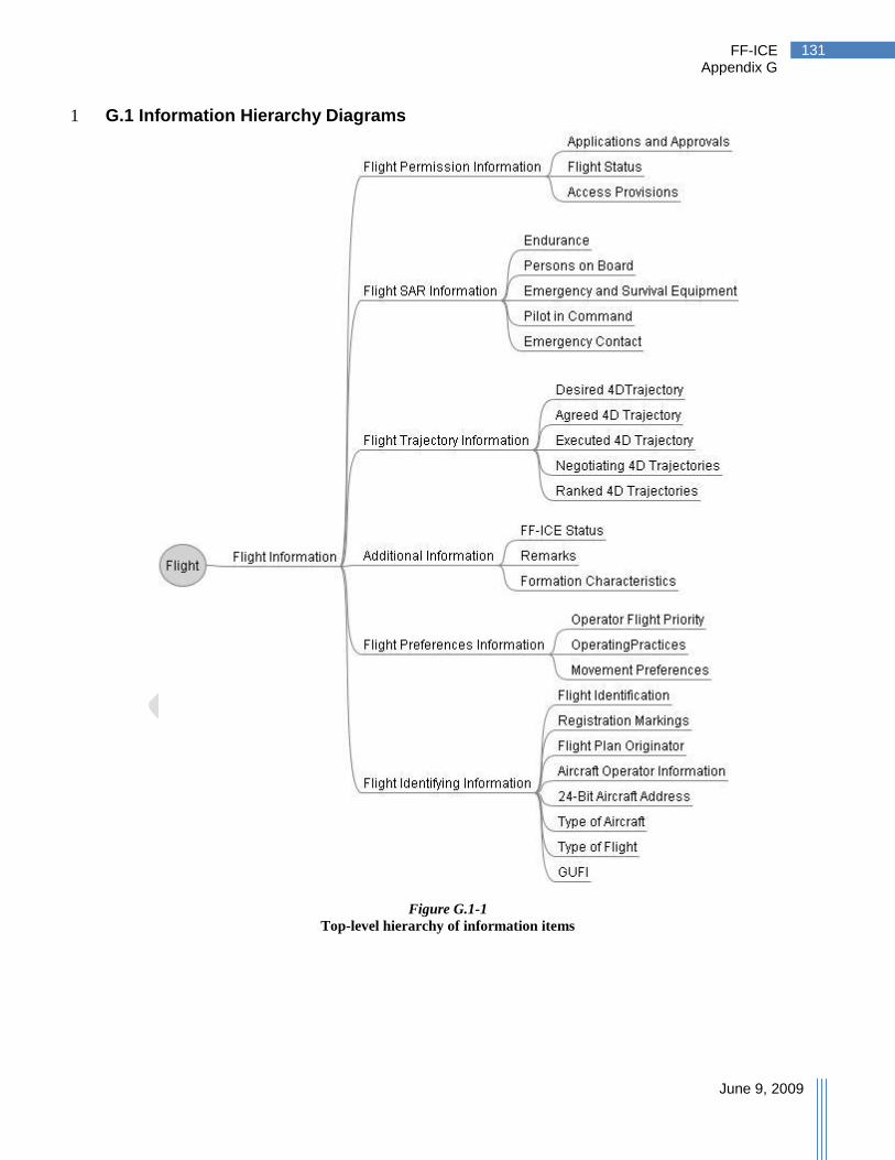
FF-ICE Appendix G
June 9, 2009
131
G.1 Information Hierarchy Diagrams 1
Figure G.1-1
Top-level hierarchy of information items

FF-ICE Appendix G
June 9, 2009
132
Figure G.1-2
Description of Trajectory Hierarchy

FF-ICE Appendix G
June 9, 2009
133
G.2 XML schema Diagrams
Figure G.2-1
Top Level Flight XML schema Diagram

FF-ICE Appendix G
June 9, 2009
134
Figure G.2-2
Airborne Element XML schema Diagram
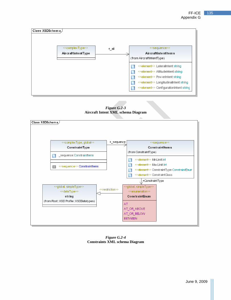
FF-ICE Appendix G
June 9, 2009
135
Figure G.2-3
Aircraft Intent XML schema Diagram
Figure G.2-4
Constraints XML schema Diagram

FF-ICE Appendix G
June 9, 2009
136
Figure G.2-5
Identifying Information XML schema Diagram

FF-ICE Appendix G
June 9, 2009
137
Figure G.2-6
Performance XML schema Diagram
Figure G.2-7
Permission XML schema Diagram
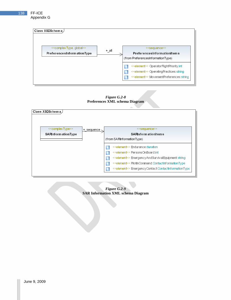
FF-ICE Appendix G
June 9, 2009
138
Figure G.2-8
Preferences XML schema Diagram
Figure G.2-9
SAR Information XML schema Diagram
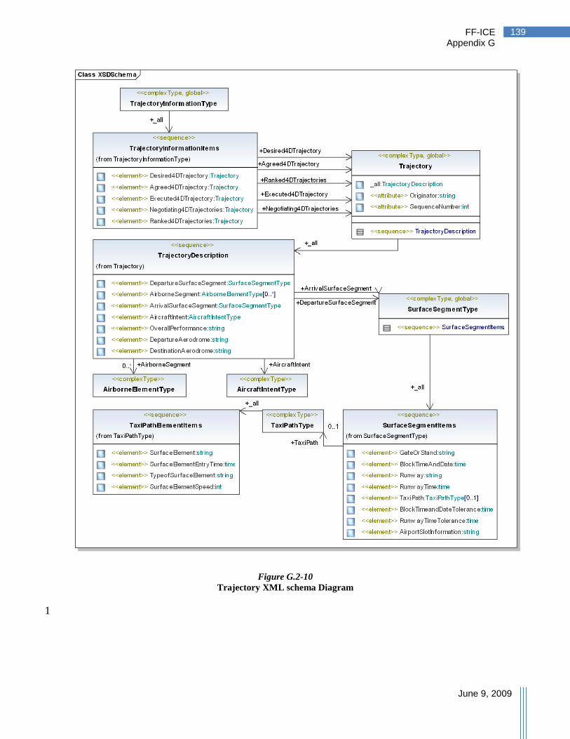
FF-ICE Appendix G
June 9, 2009
139
Figure G.2-10
Trajectory XML schema Diagram
1

FF-ICE Appendix G
June 9, 2009
140
G.3 XML schema Description Example 1
What follows below is an example of a portion of an XML schema Definition (XSD), 2
corresponding to the hierarchy described previously. An XSD would be used to define the 3
standard for the information items contained in the FF-ICE. 4
<?xml version="1.0" encoding="UTF-8"?> 5 <xsd:schema targetNamespace="http://www.FF_ICE.int" 6 xmlns:xsd="http://www.w3.org/2001/XMLSchema"> 7 <xsd:complexType name="ContactInformationType"> 8 <xsd:sequence> 9 <xsd:element name="Name" type="xsd:string"> 10 <xsd:annotation> 11 <xsd:documentation>name of contact</xsd:documentation> 12 </xsd:annotation> 13 </xsd:element> 14 <xsd:element name="PhoneNumber" minOccurs="0" maxOccurs="unbounded" 15 type="xsd:integer"> 16 <xsd:annotation> 17 <xsd:documentation>Contact phone number</xsd:documentation> 18 </xsd:annotation> 19 </xsd:element> 20 <xsd:element name="Email" minOccurs="0" maxOccurs="unbounded" 21 type="xsd:string"> 22 <xsd:annotation> 23 <xsd:documentation>Contact email 24 address</xsd:documentation> 25 </xsd:annotation> 26 </xsd:element> 27 <xsd:element name="Address" minOccurs="0" maxOccurs="unbounded" 28 type="xsd:string"> 29 <xsd:annotation> 30 <xsd:documentation>Contact address</xsd:documentation> 31 </xsd:annotation> 32 </xsd:element> 33 </xsd:sequence> 34 </xsd:complexType> 35 <xsd:element name="Flight" type="FlightType"> 36 </xsd:element> 37 <xsd:complexType name="FlightType"> 38 <xsd:sequence> 39 <xsd:element name="FlightIdentifyingInformation"> 40 <xsd:complexType> 41 <xsd:sequence> 42 <xsd:element name="FlightIdentification" 43 minOccurs="1" maxOccurs="1" type="xsd:string"> 44 <xsd:annotation> 45 <xsd:documentation>This field contains 46 the ICAO designator for the aircraft operating agency followed by the flight 47 identification number or aircraft registration. </xsd:documentation> 48 </xsd:annotation> 49 </xsd:element> 50 <xsd:element name="RegistrationMarkings" 51 minOccurs="0" maxOccurs="1" type="xsd:string"> 52 <xsd:annotation> 53

FF-ICE Appendix G
June 9, 2009
141
<xsd:documentation>Consistent with 1 current flight information, this field contains the registration markings of 2 the aircraft. </xsd:documentation> 3 </xsd:annotation> 4 </xsd:element> 5 <xsd:element name="FlightPlanOriginator" 6 minOccurs="0" maxOccurs="1" type="ContactInformationType"> 7 <xsd:annotation> 8 <xsd:documentation>Name and contact 9 information of the originator of flight plan</xsd:documentation> 10 </xsd:annotation> 11 </xsd:element> 12 <xsd:element name="AircraftOperatorInformation" 13 minOccurs="0" maxOccurs="1" type="ContactInformationType"> 14 <xsd:annotation> 15 <xsd:documentation>Name and contact 16 information of the aircraft operator. </xsd:documentation> 17 </xsd:annotation> 18 </xsd:element> 19 <xsd:element name="TypeOfFlight" 20 type="FlightTypeEnum"> 21 <xsd:annotation> 22 <xsd:documentation>This field identifies 23 the type of flight as follows: scheduled air-transport, non-scheduled air-24 transport, military, pilotless, military pilotless, general aviation, general 25 aviation – charter, or general aviation – fractional. 26 </xsd:documentation> 27 </xsd:annotation> 28 </xsd:element> 29 <xsd:element name="_24BitAircraftAddress" 30 type="_24Bit"> 31 <xsd:annotation> 32 <xsd:documentation>This field includes 33 the 24-bit ICAO address of the aircraft. </xsd:documentation> 34 </xsd:annotation> 35 </xsd:element> 36 <xsd:element name="TypeOfAircraft" type="xsd:string"> 37 <xsd:annotation> 38 <xsd:documentation>This field specifies 39 the type(s) of aircraft in a flight. </xsd:documentation> 40 </xsd:annotation> 41 </xsd:element> 42 </xsd:sequence> 43 </xsd:complexType> 44 </xsd:element> 45 [Additional XSD not included] 46