flicker technote7
TRANSCRIPT

7/27/2019 Flicker Technote7
http://slidepdf.com/reader/full/flicker-technote7 1/11
Technical Note No. 7 August 2003
VOLTAGE FLUCTUATIONS IN THEELECTRIC SUPPLY SYSTEM
This Technical Note discusses voltage fluctuations, their causes and adverse effects,what levels are acceptable and how to reduce their consequences. Integral Energy,your local Network Operator or the Integral Energy Power Quality Centre can giveyou additional advice if you have particular concerns with these issues.
Summary
Voltage fluctuations are defined as repetitive or random variations in the magnitudeof the supply voltage. The magnitudes of these variations do not usually exceed 10%of the nominal supply voltage. However, small magnitude changes occurring at particular frequencies can give rise to an effect called lamp flicker. This term is usedto describe the “impression of unsteadiness of visual sensation induced by a lightsource whose luminance or spectral distribution fluctuates with time” [1]. Flicker isessentially a measure of how annoying the fluctuation in luminance is to the humaneye. Standards limit the magnitudes of starting currents and load fluctuations of equipment to control the level of voltage fluctuations. Where the levels of indicesspecified in the standards are exceeded, mitigation techniques to reduce the effects of
voltage fluctuations are required.
Contents
1. What are voltage fluctuations?2. Effects of voltage fluctuations
3. Causes of voltage fluctuations4. Calculation of the flicker indices5. Voltage fluctuation standards and planning levels6. Reducing the effects of voltage fluctuations
7. References and additional reading8. Integral Energy Power Quality Centre
P o w e r Q u a
l i t y C e n t r e
7/27/2019 Flicker Technote7
http://slidepdf.com/reader/full/flicker-technote7 2/11
1
Power Quality Centre
1. What are voltage
fluctuations?
2. Effects of voltage
fluctuations
Voltage fluctuations can be described as repetitive or random variations of the voltage
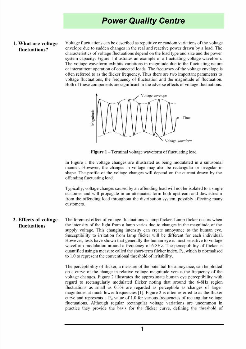
envelope due to sudden changes in the real and reactive power drawn by a load. Thecharacteristics of voltage fluctuations depend on the load type and size and the power system capacity. Figure 1 illustrates an example of a fluctuating voltage waveform.The voltage waveform exhibits variations in magnitude due to the fluctuating natureor intermittent operation of connected loads. The frequency of the voltage envelope isoften referred to as the flicker frequency. Thus there are two important parameters tovoltage fluctuations, the frequency of fluctuation and the magnitude of fluctuation.Both of these components are significant in the adverse effects of voltage fluctuations.
Voltage envelope
M a
g n i t u d e
Time
Voltage waveform
Figure 1 – Terminal voltage waveform of fluctuating load
In Figure 1 the voltage changes are illustrated as being modulated in a sinusoidalmanner. However, the changes in voltage may also be rectangular or irregular in
shape. The profile of the voltage changes will depend on the current drawn by theoffending fluctuating load.
Typically, voltage changes caused by an offending load will not be isolated to a singlecustomer and will propagate in an attenuated form both upstream and downstream
from the offending load throughout the distribution system, possibly affecting manycustomers.
The foremost effect of voltage fluctuations is lamp flicker. Lamp flicker occurs whenthe intensity of the light from a lamp varies due to changes in the magnitude of thesupply voltage. This changing intensity can create annoyance to the human eye.Susceptibility to irritation from lamp flicker will be different for each individual.However, tests have shown that generally the human eye is most sensitive to voltage
waveform modulation around a frequency of 6-8Hz. The perceptibility of flicker isquantified using a measure called the short-term flicker index, Pst, which is normalisedto 1.0 to represent the conventional threshold of irritability.
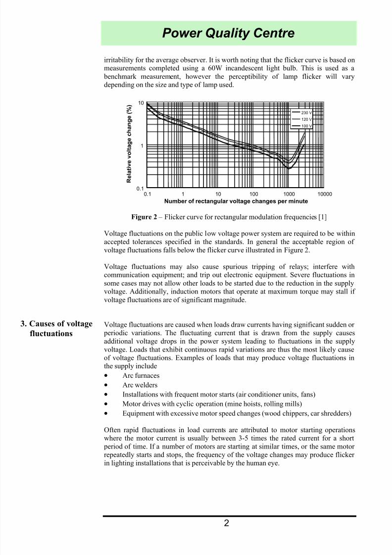
The perceptibility of flicker, a measure of the potential for annoyance, can be plottedon a curve of the change in relative voltage magnitude versus the frequency of thevoltage changes. Figure 2 illustrates the approximate human eye perceptibility withregard to rectangularly modulated flicker noting that around the 6-8Hz region
fluctuations as small as 0.3% are regarded as perceptible as changes of larger magnitudes at much lower frequencies [1]. Figure 2 is often referred to as the flicker
curve and represents a Pst value of 1.0 for various frequencies of rectangular voltagefluctuations. Although regular rectangular voltage variations are uncommon in practice they provide the basis for the flicker curve, defining the threshold of
7/27/2019 Flicker Technote7
http://slidepdf.com/reader/full/flicker-technote7 3/11
2
Power Quality Centre
3. Causes of voltage
fluctuations
irritability for the average observer. It is worth noting that the flicker curve is based onmeasurements completed using a 60W incandescent light bulb. This is used as a
benchmark measurement, however the perceptibility of lamp flicker will varydepending on the size and type of lamp used.
Figure 2 – Flicker curve for rectangular modulation frequencies [1]
Voltage fluctuations on the public low voltage power system are required to be withinaccepted tolerances specified in the standards. In general the acceptable region of voltage fluctuations falls below the flicker curve illustrated in Figure 2.
Voltage fluctuations may also cause spurious tripping of relays; interfere withcommunication equipment; and trip out electronic equipment. Severe fluctuations in
some cases may not allow other loads to be started due to the reduction in the supply
voltage. Additionally, induction motors that operate at maximum torque may stall if voltage fluctuations are of significant magnitude.
Voltage fluctuations are caused when loads draw currents having significant sudden or periodic variations. The fluctuating current that is drawn from the supply causesadditional voltage drops in the power system leading to fluctuations in the supplyvoltage. Loads that exhibit continuous rapid variations are thus the most likely causeof voltage fluctuations. Examples of loads that may produce voltage fluctuations inthe supply include
• Arc furnaces
• Arc welders
• Installations with frequent motor starts (air conditioner units, fans)
• Motor drives with cyclic operation (mine hoists, rolling mills)
• Equipment with excessive motor speed changes (wood chippers, car shredders)
Often rapid fluctuations in load currents are attributed to motor starting operationswhere the motor current is usually between 3-5 times the rated current for a short period of time. If a number of motors are starting at similar times, or the same motor repeatedly starts and stops, the frequency of the voltage changes may produce flicker in lighting installations that is perceivable by the human eye.
0.1
1
10
0.1 1 10 100 1000 10000Number of rectangular voltage changes per minute
230 V
120 V
100 V
R e l a t i v e v o l t a g e c h a n g e ( % )

7/27/2019 Flicker Technote7
http://slidepdf.com/reader/full/flicker-technote7 4/11
3
Power Quality Centre
Consider the simple model representing a fluctuating load drawing real power P, andreactive power Q, connected to a power system with an impedance of resistance R,
and reactance X, as illustrated in Figure 3. The voltage VR seen by the customer canusually be regulated by operating the system voltage VS at a slightly higher value toensure V
R remains at the required value, e.g. 230V for a single-phase system. During
steady state operation this can be achieved through the use of automatic tap changerson transformers, line drop compensators and voltage regulators. For more rapidchanges in load current the operation of such devices is not fast enough in response toeffectively regulate the voltage to stay at the required value.
The resultant voltage due to the current drawn by the load is illustrated in the phasor diagram of Figure 4 where VS is the supply voltage and VR is the resultant voltageseen by the load at the point of common connection (PCC).
~VS
~I
Fluctuating load
(P + jQ)
System impedanceSupply
R X
~VR
PCC
Figure 3 – Simple model of power system
~I = Id - jIq
~
VR
~VS
~IR
j~IX
Figure 4 - Phasor diagram of supply voltage
The complex power drawn by the fluctuating load and the voltage phasors can bedescribed by equations (1) and (2) respectively.
~VR
~*I = P + jQ (1)
~VS =
~VR +
~I (R + jX) (2)
Expanding equation (2) for the voltage phasors provides the following
~VS =
~VR + (Id - jIq) (R + jX) (3)
= (VR + R Id + X Iq) + j(X Id – R Iq) (4)
Ignoring the phase differences between VR and VS in equation (4) and equating only
the real parts
VS = VR + R Id + X Iq (5)

7/27/2019 Flicker Technote7
http://slidepdf.com/reader/full/flicker-technote7 5/11
4
Power Quality Centre
4. Calculation of
flicker indices
Assuming VS is a very strong supply system, i.e. VS remains constant regardless of thecurrent drawn by the fluctuating load, for any changes in Id and Iq the changes in VR
will be as follows
0 = ∆VR + R ∆Id + X ∆Iq (6)
∆VR = - (R ∆Id + X ∆Iq) (7)
Equation (7) can be re-written in per unit, i.e. in terms of the changes in real andimaginary power drawn by the fluctuating load
∆VR = - (R ∆P + X ∆Q) (8)
If R is negligible, then the reactance X = 1 / Fault level, leading to equation (9)
∆VR = - ∆Q / Fault level (9)
Thus, it can be seen that the voltage at the point of common connection is essentially afunction of the reactive power variation of the load and supply system characteristics. Note that for low voltage systems where R is considerably larger the real power mayalso contribute significantly to voltage variations.
There are two major indices used in the evaluation of flicker in power systems, theshort-term flicker index, Pst as stated before, and the long-term flicker index, Plt. The
Pst index represents the perceptibility of flicker based on a criterion that flicker levelscreated by voltage fluctuations will annoy 50% of population. This index is calculatedon a 10-minute basis to evaluate short-term flicker levels. For a periodic rectangular voltage fluctuation, this index, normalised to a value of 1.0, is illustrated in Figure 2
as the flicker curve.
Calculation of Pst values is performed by a flickermeter. The design specification andfunctionality of a flickermeter is outlined in Australian standards AS 4376 and
AS 4377. Figure 5 illustrates the functional block diagram of a flickermeter as per thestandards. The first three blocks of the design perform the signal conditioningoperation on the measured voltage waveform v(t). More specifically these blocksrepresent how the voltage fluctuations are transformed to light fluctuations, determinethe perceptibility to the human eye and then simulate the brain response (annoyance)to lamp flicker. This process is often referred to as the “lamp-eye-brain” response. Thefinal block performs the statistical analysis required to calculate Pst and Plt.
Plt Weighting
filters Squaring and
smoothing
Statisticalevaluation of
flicker level
v(t)
Pst
Square law
demodulator
Instantaneous flicker
sensation level Pf (t)
AS 4376 AS 4377
1 2 3 4
Figure 5 – Functional block diagram of a flickermeter
7/27/2019 Flicker Technote7
http://slidepdf.com/reader/full/flicker-technote7 6/11
5
Power Quality Centre
5. Voltage
fluctuation
standards and
planning levels
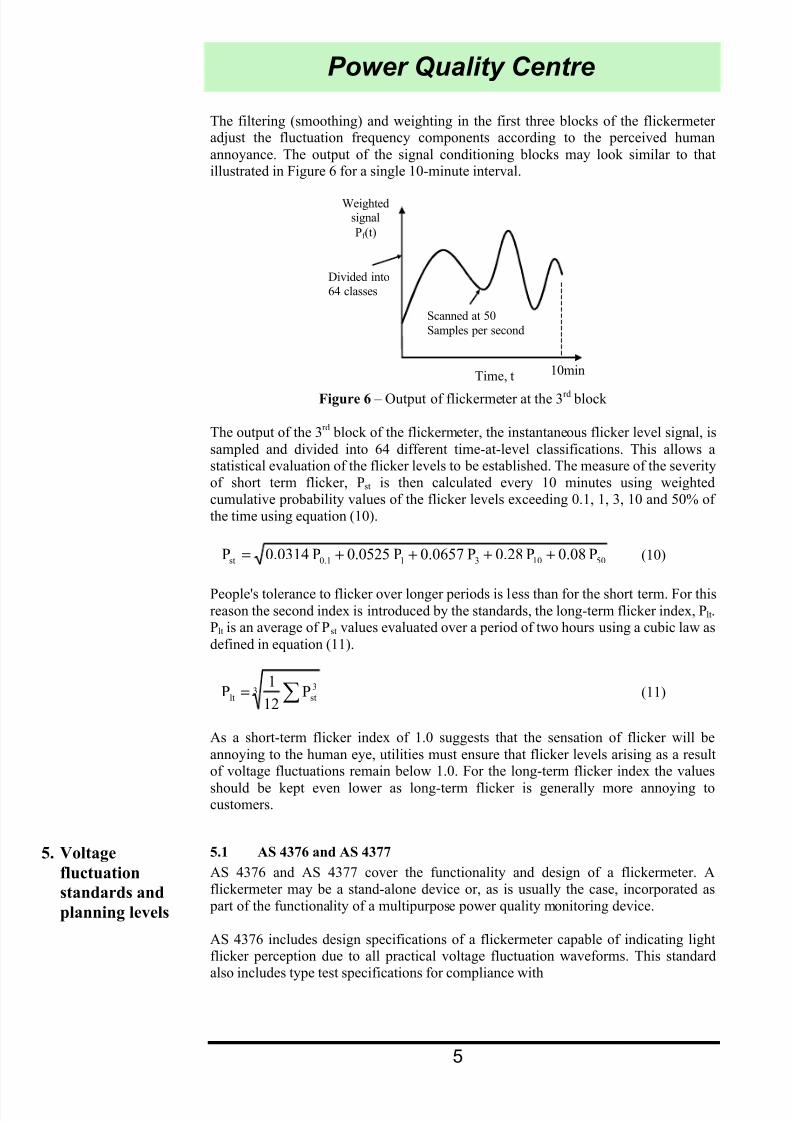
The filtering (smoothing) and weighting in the first three blocks of the flickermeter adjust the fluctuation frequency components according to the perceived human
annoyance. The output of the signal conditioning blocks may look similar to thatillustrated in Figure 6 for a single 10-minute interval.
Divided into
64 classes
Time, t
Scanned at 50
Samples per second
10min
Weightedsignal
Pf (t)
Figure 6 – Output of flickermeter at the 3rd block
The output of the 3rd block of the flickermeter, the instantaneous flicker level signal, is
sampled and divided into 64 different time-at-level classifications. This allows astatistical evaluation of the flicker levels to be established. The measure of the severityof short term flicker, Pst is then calculated every 10 minutes using weightedcumulative probability values of the flicker levels exceeding 0.1, 1, 3, 10 and 50% of the time using equation (10).
5010310.1st P0.08P0.28P0.0657P0.0525P0.0314P ++++= (10)
People's tolerance to flicker over longer periods is less than for the short term. For thisreason the second index is introduced by the standards, the long-term flicker index, P lt.Plt is an average of Pst values evaluated over a period of two hours using a cubic law as
defined in equation (11).
3 3
stlt P12
1P ∑= (11)
As a short-term flicker index of 1.0 suggests that the sensation of flicker will be
annoying to the human eye, utilities must ensure that flicker levels arising as a resultof voltage fluctuations remain below 1.0. For the long-term flicker index the values
should be kept even lower as long-term flicker is generally more annoying tocustomers.
5.1 AS 4376 and AS 4377
AS 4376 and AS 4377 cover the functionality and design of a flickermeter. Aflickermeter may be a stand-alone device or, as is usually the case, incorporated as part of the functionality of a multipurpose power quality monitoring device.
AS 4376 includes design specifications of a flickermeter capable of indicating lightflicker perception due to all practical voltage fluctuation waveforms. This standardalso includes type test specifications for compliance with

7/27/2019 Flicker Technote7
http://slidepdf.com/reader/full/flicker-technote7 7/11
6
Power Quality Centre
• Rectangular and sinusoidal voltage fluctuations (for specified frequency and
percentage change in voltage), and
• Environmental tests such as EMC and climatic tests.
AS 4377 provides details for the statistical evaluation methods for both short-term andlong-term flicker severity. The statistical analysis emulates the perception of the lamp-eye-brain chain providing the quantified outputs Pst and Plt. Calculations are
completed on-line resulting in Pst values for each 10-minute interval and Plt valuesusing the cube law every two hour interval.
5.2 AS/NZS 61000.3.3
AS/NZS 61000.3.3 specifies the emission limits for low voltage equipment rated lessthan or equal to 16A to ensure excessive voltage fluctuations are not caused by their normal operation. The standard outlines the test conditions for type tests on the
equipment (cookers, lighting equipment, washing machines, tumbler dryers,refrigerators, copying machines, laser printers, vacuum cleaners, food mixers, portable
tools, hair dryers, consumer electronics, direct water heaters).
To measure voltage fluctuations caused by the operation of specific loads themagnitude of change in the rms voltage is considered every half cycle (10ms) of mains frequency for all the rms values of voltage over each 10-minute interval. The
voltage change characteristics ∆V(t) shown in Figure 7 is then determined for periods between when the voltage has been in steady state for at least one second. A referencesystem impedance is specified to be used during the type tests.
Time, t
V(t)
∆V
∆V
∆Vmax
Figure 7 – Histogram evaluation of ∆V(t)
5.3 AS/NZS 61000.3.5
AS/NZS 61000.3.5 covers the specifications outlined in AS/NZS 61000.3.3 for low
voltage equipment with rated current greater than 16A. This standard differs however in that it uses the actual point of connection to perform the compliance tests rather than a reference impedance. Thus to perform the evaluation of this equipment the
consumer and electricity supplier must cooperate and provide the necessary data toallow an evaluation to take place. Such data may include load details, systemimpedance, existing level of disturbance, and cost of power supply improvements.
5.4 AS/NZS 61000.3.7
The Australian standard which specifies the limits for “fluctuating loads in MV andHV power systems” is based on the IEC report of the same name, IEC 61000-3-7:1996. This IEC report is a Technical Report – Type 3, meaning it does not have thesame standing as an international standard but may be referred to for assistance in
setting limits for customers. However in Australia this document has been adopted as

7/27/2019 Flicker Technote7
http://slidepdf.com/reader/full/flicker-technote7 8/11
7
Power Quality Centre
6. Reducing the
effects of voltage
fluctuations
a standard. This standard is required to ensure the interaction of all loads connected tothe power system does not cause excessive voltage fluctuations. Each customer is
allocated certain limits to ensure the impact of the operation of their loads isacceptable with regards to flicker.
The primary objective of this standard is to provide guidance for engineering practices. The given guidelines are based on certain simplifying assumptions andhence recommended approaches are to be used with flexibility and judgement. Thefinal decision for connection of a customer’s fluctuating load will always rest with theelectricity supplier.
Compatibility levels for voltage fluctuations are set as shown in Table 1 for the short-term and long-term flicker indices. Utilities should endeavour to ensure flicker indicesdo not exceed the compatibility levels recommended by the relevant standards. For this reason utilities should allocate planning levels below the compatibility levels. The
planning levels for MV and HV systems recommended in the standard are given in
Table 2.
Table 1 - Compatibility levels for LV and MV systems
Pst 1.0
Plt 0.8
Table 2 - Planning levels for MV and HV and EHV systems
MV HV-EHV
Pst 0.9 0.8
Plt 0.7 0.6
The general procedure for evaluating fluctuating loads as per the AS/NZS 61000.3.7standard is completed in stages. Stage 1 is a simplified evaluation of disturbance
emission. If the fluctuating load or the customers maximum demand is smallcompared to the short circuit capacity at the point of common connection, no detailedevaluation is necessary. Stage 2 calculates emission limits proportional to maximumdemand. Equipment is evaluated against system absorption capacity that is allocatedto individual customers according to their demand. Absorption capacity is derivedfrom planning levels. In allocating to individual customers at MV levels, disturbancesderived from HV levels should be considered. The final stage is acceptance of higher emission levels on an exceptional and precarious basis where utility and consumer may agree on the connection with special conditions.
5.5 AS/NZS 61000.3.11
This standard covers the conditional connection of loads that come under thespecifications outlined in AS/NZS 61000.3.5 but do not meet compliance.
To allow equipment connected to the power system to operate correctly it is importantfor both the utility and their customers to ensure that the operating voltage of thesystem remains within the boundaries set by the appropriate standards. As mentioned
previously power system equipment does not usually provide adequate response timefor mitigation of rapid voltage changes. It is inherent that complete compensation of
flicker is not possible [7]. However, the magnitude of the voltage fluctuations may be

7/27/2019 Flicker Technote7
http://slidepdf.com/reader/full/flicker-technote7 9/11
8
Power Quality Centre
7. References and
additional reading
reduced using one of the following network strategies
• Increasing the fault level at the point of connection. Strengthening the system or reconnecting the offending load at a higher voltage level can achieve this.
• Decrease the reactive power flow through the network due to the load. This
may be achieved through the use of a Static VAr Compensator (SVC) and willhelp reduce voltage sags.
• Strengthening the network reactive power compensation. A larger number of smaller capacitor banks distributed throughout a system will allow finer tuningof reactive power requirements [7].
Frequent motor starting has been highlighted as a significant cause of flicker. This isespecially significant for larger single-phase air conditioner compressor motorsconnected to weak low voltage distribution systems. In order reduce the magnitude of voltage fluctuations a reduction in the starting current of a motor must beaccomplished. This can be achieved through the use of various starting techniques. [7]
suggests the use of the following motor starting techniques
• Inclusion of an intermediate star-delta resistance-delta starting configuration for three-phase motor applications.
• Installing a series resistance or inductance with the motor stator to effectivelyapply reduced voltage starting.
• Use of an exclusive autotransformer matched to the design of the motor.
• Soft start using power electronic soft starters.
• Full inverter control of motor. This has the advantage of controllable speed and
torque providing efficient motor operation.
As frequency is also an important parameter of voltage variations a reduction in thenumber of motor starts may also lessen the effects of flicker. This may be achieved
through coordinated control of motors or by providing sufficient storage of heat for the case of air conditioners and heat pumps [8].
1. AS/NZS 61000.3.3:1998, “Electromagnetic compatibility (EMC) Part 3.3:
Limits – Limitation of voltage fluctuations and flicker in low-voltage supplysystems for equipment with rated current less than or equal to 16A”, Australian
Standards, 1998.2. AS/NZS 61000.3.5:1998, “Electromagnetic compatibility (EMC) Part 3.5:
Limits – Limitation of voltage fluctuations and flicker in low-voltage supplysystems for equipment with rated current greater than 16A”, Australian
Standards, 1998.3. AS/NZS 61000.3.7:2001, “Electromagnetic compatibility (EMC) Part 3.7:
Limits – Assessment of emission limits for fluctuating loads in MV and HV power systems”, Australian Standards, 2001.
4. AS/NZS 61000.3.11:2002, “Electromagnetic compatibility (EMC) Part 3.11:Limits – Limitation of voltage changes, voltage fluctuations and flicker in public low-voltage supply systems – Equipment with rated current less than or equal to 75A and subject to conditional connection”, Australian Standards,2002.
5. AS/NZS 4376:1996, “Flickermeter – Functional and design specifications”,Australian Standards, 1996.
6. AS/NZS 4377:1996, “Flickermeter – Evaluation of flicker severity”, Australian
Standards, 1996.
7/27/2019 Flicker Technote7
http://slidepdf.com/reader/full/flicker-technote7 10/11
9
Power Quality Centre
8. Integral Energy
Power Quality
Centre
7. Iglesias et al, “Power Quality in European electricity supply networks”, 1st
Edition, Euroelectric, Brussels, 2002.8. Morcos and Gomez, “Flicker sources and mitigation”, IEEE Power Engineering
Review, November 2002.
In July 1996, Integral Energy set up Australia's first Power Quality Centre at theUniversity of Wollongong. The Centre's objective is to work with industry to improvethe quality and reliability of the electricity supply to industrial, commercial anddomestic users. The Centre specialises in research into the control of distortion of thesupply voltage, training in power quality issues at all levels, and specialisedconsultancy services for solution of power quality problems. You are invited tocontact the Centre if you would like further advice on quality of supply.
ABOUT THE AUTHORS
Duane Robinson is a Lecturer in the School of Electrical, Computer and
Telecommunications Engineering at the University of Wollongong. The IntegralEnergy Power Quality Centre sponsors his position.
Sarath Perera is a Senior Lecturer in the School of Electrical, Computer and
Telecommunications Engineering at the University of Wollongong.
Vic Gosbell is the Technical Director of the Integral Energy Power Quality Centre andProfessor of Power Engineering in the School of Electrical, Computer andTelecommunications Engineering at the University of Wollongong.
Vic Smith is a Research Engineer for the Integral Energy Power Quality Centre.
7/27/2019 Flicker Technote7
http://slidepdf.com/reader/full/flicker-technote7 11/11
Power Quality Centre
FURTHER INFORMATION CAN BE OBTAINED BY CONTACTING:
Professor V.J. Gosbell
Technical Director
Integral Energy Power Quality Centre
School of Electrical, Computer & Telecommunications Engineering
University of Wollongong
NSW AUSTRALIA 2522
Ph: (02) 4221 3065 or (02) 4221 3402 Fax: (02) 4221 3236
Email: [email protected]