flexible solutions in control and load switches - mc …€¦ · flexible solutions in control and...
TRANSCRIPT

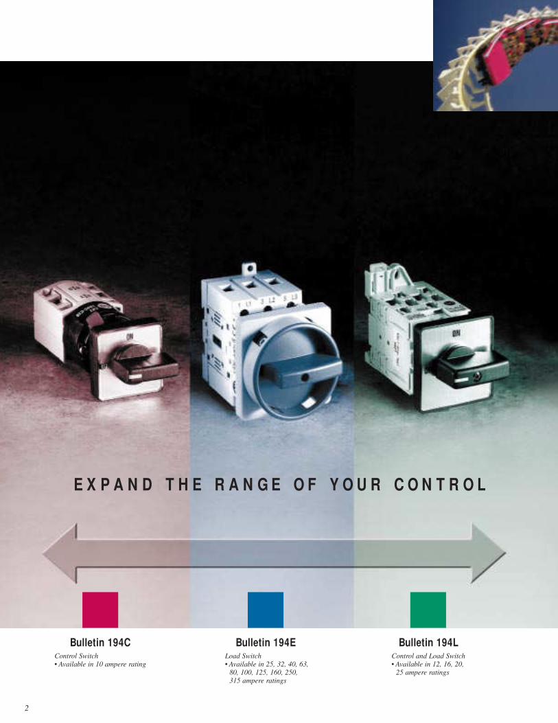
Flexible Solutions in Control
and Load Switches
Bulletins 194C, 194E, 194L
2
Bulletin 194C Bulletin 194E Bulletin 194LControl Switch
• Available in 10 ampere rating
Load Switch
• Available in 25, 32, 40, 63,
80, 100, 125, 160, 250,
315 ampere ratings
Control and Load Switch
• Available in 12, 16, 20,
25 ampere ratings
E X P A N D T H E R A N G E O F Y O U R C O N T R O L
Many of your applications require control and load
switches capable of handling inductive energy levels —
higher than those seen by a typical selector switch and
with lower interrupting ratings than UL 98/1087 fusible
disconnects. Allen-Bradley offers a full line of control and
load switches as part of its high quality family of motor
management solutions for these demanding requirements.
Flexible and adaptable devices feature:• 10 - 100A switch sizes
• improved horsepower ratings
(0.75 to 100 HP)
• compact switch package
to save space
• reduced installation time
• world-class approvals —
UL/CSA/CE
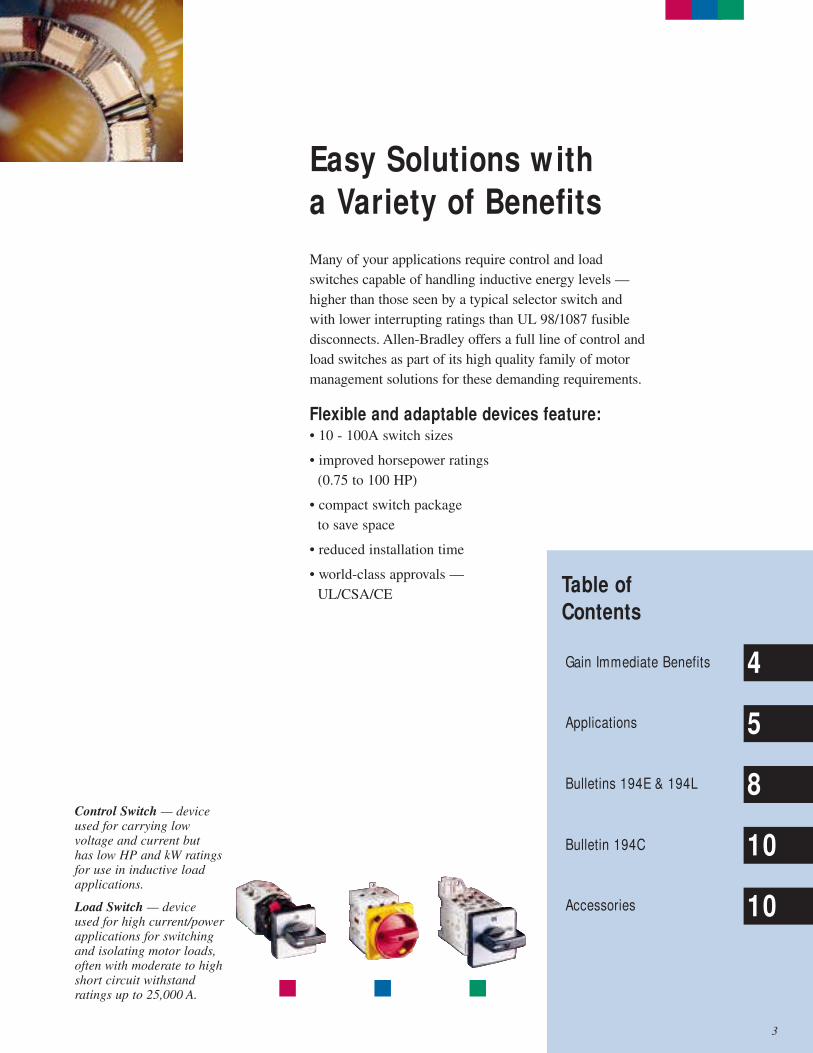
Control Switch — deviceused for carrying lowvoltage and current but has low HP and kW ratingsfor use in inductive loadapplications.
Load Switch — device used for high current/powerapplications for switchingand isolating motor loads,often with moderate to highshort circuit withstandratings up to 25,000 A.
Easy Solutions with
a Variety of Benefits
Table of
Contents
Gain Immediate Benefits
Applications
Bulletins 194E & 194L
Bulletin 194C
Accessories
4
5
8
10
10
3
4
From reducing installation time to increasing operator
safety, control and load switches offer a wide range of
features with immediate benefits.
Gain Immediate
Benefits
Feature Benefit
Extended range up to 100 HP
Positive-guided actuation
Bulletin 194E snap-on poles and
auxiliaries up to 100 amperes
Bulletin 194L gold-flashed
power poles
Universal handle mountings
Captive terminal screws/
self-lifting pressure plates
Pad-lockable handles
Handles can mount
in 22.5 mm openings
Similar handles for
Bulletins 194C, 194E, 194L
Total insulation/IP2X finger
safe design
UL approved/CSA Certified/
CE compliant
Save panel space by using
smaller switch for same load
Add safety by breaking contact
welds after high fault current
Field modifiable/ease of
installation
Low energy fidelity on control
switches to 17V DC 5ma
Reduces installation time
with simple conversion
from competitive switches
Ease of wiring saves time
Complies with OSHA and IEC
lock-out/tag-out rules
Time saving installation
with single-hole to five-
hole installation
Family appearance across
product range
Prevent shock hazard from
personal contact with high
voltage
Global acceptability
5
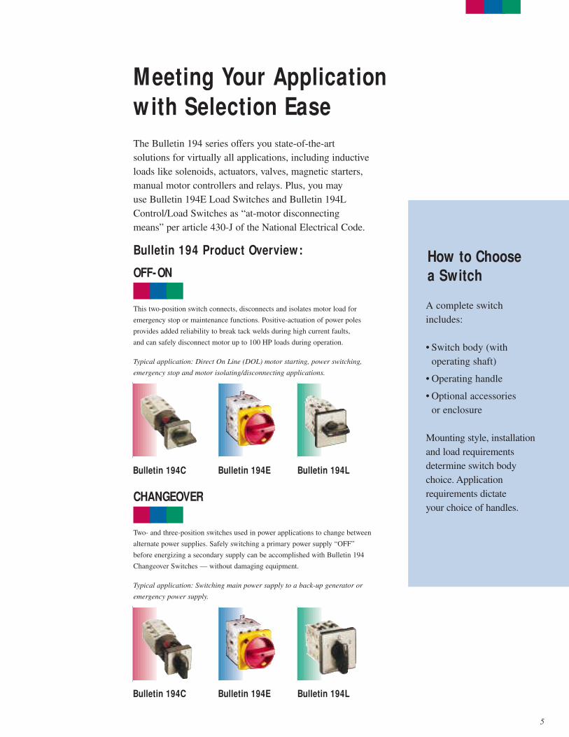
This two-position switch connects, disconnects and isolates motor load for
emergency stop or maintenance functions. Positive-actuation of power poles
provides added reliability to break tack welds during high current faults,
and can safely disconnect motor up to 100 HP loads during operation.
Typical application: Direct On Line (DOL) motor starting, power switching,
emergency stop and motor isolating/disconnecting applications.
The Bulletin 194 series offers you state-of-the-art
solutions for virtually all applications, including inductive
loads like solenoids, actuators, valves, magnetic starters,
manual motor controllers and relays. Plus, you may
use Bulletin 194E Load Switches and Bulletin 194L
Control/Load Switches as “at-motor disconnecting
means” per article 430-J of the National Electrical Code.
Bulletin 194 Product Overview:
OFF-ON
CHANGEOVER
Bulletin 194C Bulletin 194E
Bulletin 194E
Bulletin 194L
How to Choose
a Switch
Two- and three-position switches used in power applications to change between
alternate power supplies. Safely switching a primary power supply “OFF”
before energizing a secondary supply can be accomplished with Bulletin 194
Changeover Switches — without damaging equipment.
Typical application: Switching main power supply to a back-up generator or
emergency power supply.
Bulletin 194C Bulletin 194L
Meeting Your Application
with Selection Ease
A complete switch
includes:
• Switch body (with
operating shaft)
• Operating handle
• Optional accessories
or enclosure
Mounting style, installation
and load requirements
determine switch body
choice. Application
requirements dictate
your choice of handles.
6
Bulletin 194L
Meeting your Application
with Selection Ease continued
Bulletin 194 Product Overview: continued
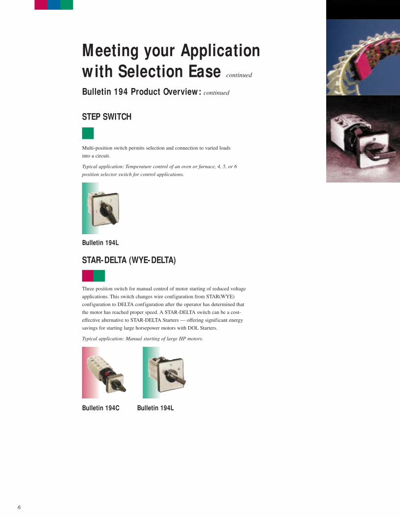
Three position switch for manual control of motor starting of reduced voltage
applications. This switch changes wire configuration from STAR(WYE)
configuration to DELTA configuration after the operator has determined that
the motor has reached proper speed. A STAR-DELTA switch can be a cost-
effective alternative to STAR-DELTA Starters — offering significant energy
savings for starting large horsepower motors with DOL Starters.
Typical application: Manual starting of large HP motors.
STAR-DELTA (WYE-DELTA)
Bulletin 194C Bulletin 194L
STEP SWITCH
Multi-position switch permits selection and connection to varied loads
into a circuit.
Typical application: Temperature control of an oven or furnace, 4, 5, or 6
position selector switch for control applications.

Multi-position switch connects a customer-supplied voltmeter across motor
phases or from a single phase to ground to permit safe measurement of motor
voltages during operation. Promotes cost savings by not requiring a voltmeter
for each motor circuit.
Typical application: Instrumentation/diagnostics of motor phase voltage.
VOLTMETER SWITCH
Bulletin 194C Bulletin 194L
Multi-position switch manually connects one customer-supplied ammeter into
each phase of a 3-phase system without causing a phase loss condition due to
introduction of a meter into the motor circuit. This promotes cost savings by
not requiring an ammeter for each motor circuit.
Typical application: Instrumentation/diagnostics of motor phase current.
AMMETER SWITCH
Bulletin 194C Bulletin 194L
Material handling and
other environment
conditions can be very
demanding for load
switches. Particularly
in food processing
applications where
washdown requirements
are just as important
as electrical reliability
and personnel safety.
Here are typical at-motor
disconnect requirements,
per Article 430-J 1999
of the National Electrical
Code:
• located “At the Motor”
• located in the line
of sight
• lockable in the
“OFF” position
• HP rated to break
locked rotor current
• poles open simultaneously
• fusing not required if
upstream branch is fused
7
Three-position switch (Forward - OFF - Reverse) for control of motor rotation.
Engaging the switch safely changes the wiring configuration to reverse a
motor’s direction — without causing damage to the motor.
Typical application: Conveyor and material handling.
REVERSING SWITCH
Bulletin 194C Bulletin 194L
8
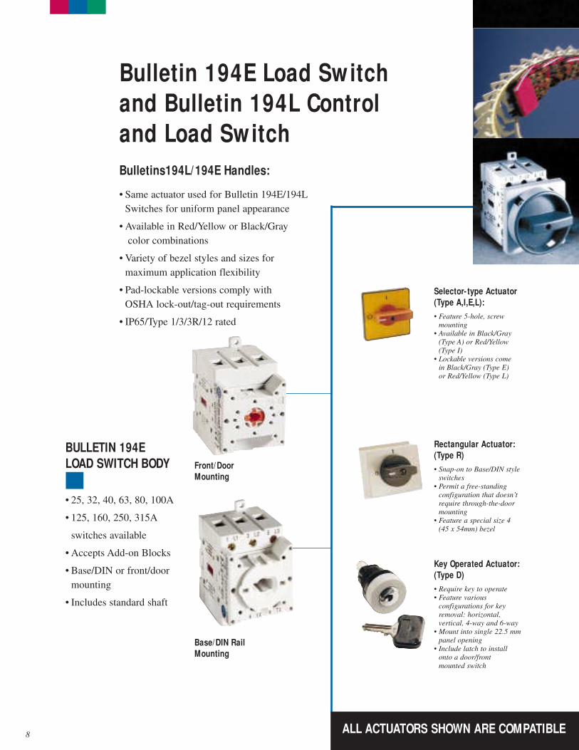
Selector- type Actuator
(Type A,I,E,L):
• Feature 5-hole, screw
mounting
• Available in Black/Gray
(Type A) or Red/Yellow
(Type I)
• Lockable versions come
in Black/Gray (Type E)
or Red/Yellow (Type L)
Front/Door
Mounting
Base/DIN Rail
Mounting
Rectangular Actuator:
(Type R)
• Snap-on to Base/DIN style
switches
• Permit a free-standing
configuration that doesn’t
require through-the-door
mounting
• Feature a special size 4
(45 x 54mm) bezel
Bulletin 194E Load Switch
and Bulletin 194L Control
and Load Switch
Bulletins194L/194E Handles:
• Same actuator used for Bulletin 194E/194L
Switches for uniform panel appearance
• Available in Red/Yellow or Black/Gray
color combinations
• Variety of bezel styles and sizes for
maximum application flexibility
• Pad-lockable versions comply with
OSHA lock-out/tag-out requirements
• IP65/Type 1/3/3R/12 rated
BULLETIN 194E
LOAD SWITCH BODY
• 25, 32, 40, 63, 80, 100A
• 125, 160, 250, 315A
switches available
• Accepts Add-on Blocks
• Base/DIN or front/door
mounting
• Includes standard shaft
Key Operated Actuator:
(Type D)
• Require key to operate
• Feature various
configurations for key
removal: horizontal,
vertical, 4-way and 6-way
• Mount into single 22.5 mm
panel opening
• Include latch to install
onto a door/front
mounted switch
ALL ACTUATORS SHOWN ARE COMPATIBLE
9
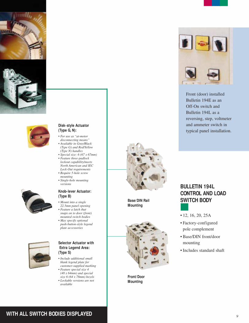
Front (door) installed
Bulletin 194E as an
Off-On switch and
Bulletin 194L as a
reversing, step, voltmeter
and ammeter switch in
typical panel installation.
BULLETIN 194L
CONTROL AND LOAD
SWITCH BODYBase/DIN Rail
Mounting
Front/Door
Mounting
Knob- lever Actuator:
(Type B)
• Mount into a single
22.5mm panel opening
• Feature a latch that
snaps on to door (front)
mounted switch bodies
• May specify optional
push-button-style legend
plate accessories
Disk-style Actuator
(Type G, N):
• For use as “at-motor
disconnecting means”
• Available in Gray/Black
(Type G) and Red/Yellow
(Type N) handles
• Special size: 6 (67 x 67mm)
• Feature three-padlock
lockout capability/meets
North American and IEC
Lock-Out requirements
• Require 5-hole screw
mounting
• Single-hole mounting
versions
• 12, 16, 20, 25A
• Factory-configured
pole complement
• Base/DIN front/door
mounting
• Includes standard shaft
Selector Actuator with
Extra Legend Area:
(Type S)
• Include additional small
blank legend plate for
customer-supplied marking
• Feature special size 4
(48 x 64mm) and special
size 6 (64 x 78mm) bezels
• Lockable versions are not
available
WITH ALL SWITCH BODIES DISPLAYED
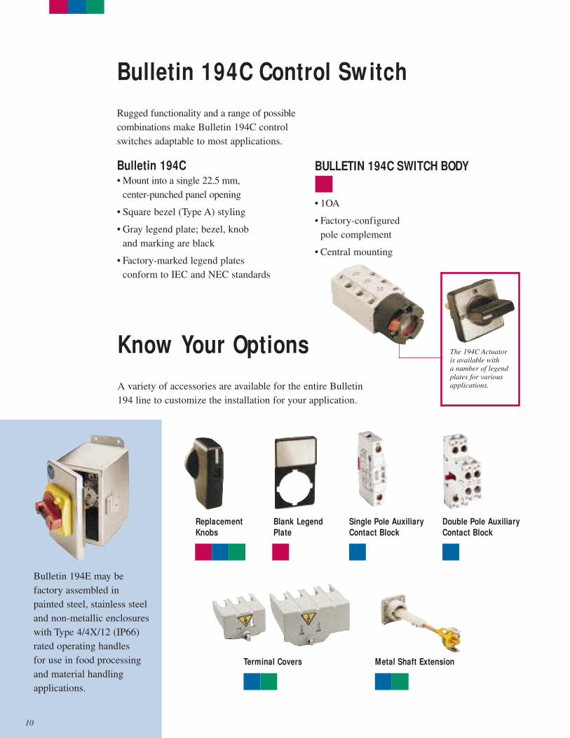
Know Your Options
A variety of accessories are available for the entire Bulletin
194 line to customize the installation for your application.
Bulletin 194E may be
factory assembled in
painted steel, stainless steel
and non-metallic enclosures
with Type 4/4X/12 (IP66)
rated operating handles
for use in food processing
and material handling
applications.
Replacement
Knobs
Blank Legend
Plate
Terminal Covers Metal Shaft Extension
Single Pole Auxiliary
Contact Block
Double Pole Auxiliary
Contact Block
Bulletin 194C Control Switch
Rugged functionality and a range of possible
combinations make Bulletin 194C control
switches adaptable to most applications.
Bulletin 194C• Mount into a single 22.5 mm,
center-punched panel opening
• Square bezel (Type A) styling
• Gray legend plate; bezel, knob
and marking are black
• Factory-marked legend plates
conform to IEC and NEC standards
The 194C Actuator
is available with
a number of legend
plates for various
applications.
BULLETIN 194C SWITCH BODY
• 1OA
• Factory-configured
pole complement
• Central mounting
10
Bulletin 194C, 194E, 194L
IEC Control and Load Switches
11
Section Overview
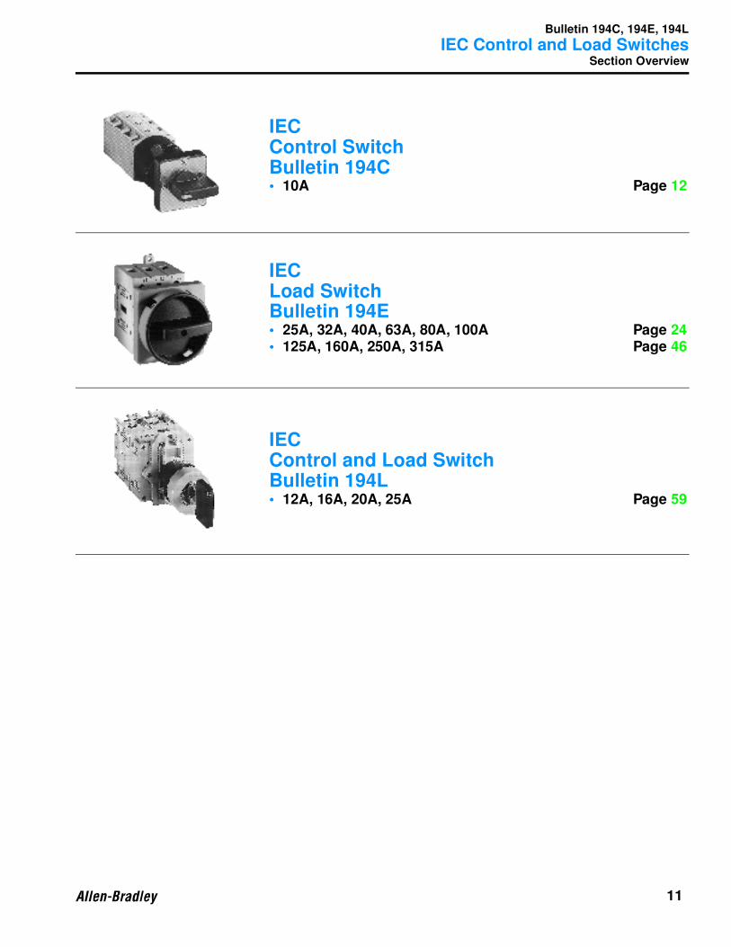
IECControl SwitchBulletin 194C• 10A Page 12
IECLoad SwitchBulletin 194E• 25A, 32A, 40A, 63A, 80A, 100A Page 24• 125A, 160A, 250A, 315A Page 46
IECControl and Load SwitchBulletin 194L• 12A, 16A, 20A, 25A Page 59
Bulletin 194C
IEC Control Switches
12
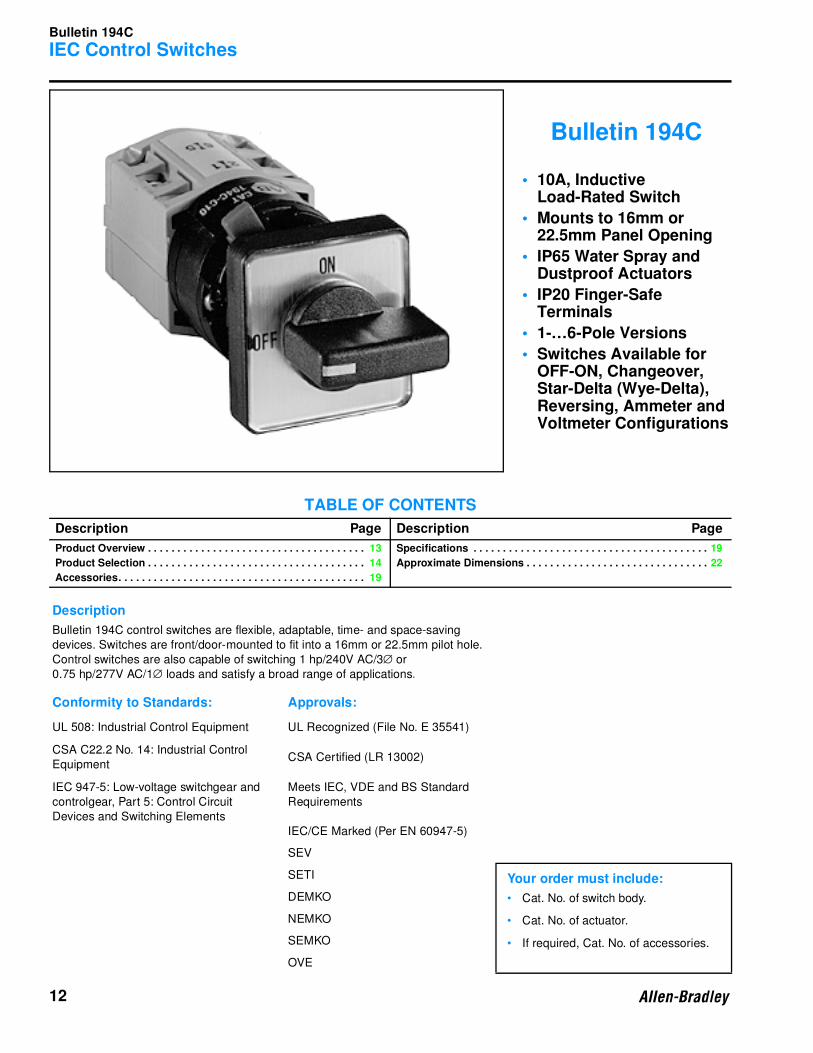
Bulletin 194C
• 10A, Inductive Load-Rated Switch
• Mounts to 16mm or 22.5mm Panel Opening
• IP65 Water Spray and Dustproof Actuators
• IP20 Finger-Safe Terminals
• 1-…6-Pole Versions
• Switches Available for OFF-ON, Changeover, Star-Delta (Wye-Delta), Reversing, Ammeter and Voltmeter Configurations
TABLE OF CONTENTS
Description Page Description Page
Product Overview . . . . . . . . . . . . . . . . . . . . . . . . . . . . . . . . . . . . . 13
Product Selection . . . . . . . . . . . . . . . . . . . . . . . . . . . . . . . . . . . . . 14
Accessories. . . . . . . . . . . . . . . . . . . . . . . . . . . . . . . . . . . . . . . . . . 19
Specifications . . . . . . . . . . . . . . . . . . . . . . . . . . . . . . . . . . . . . . . . 19
Approximate Dimensions . . . . . . . . . . . . . . . . . . . . . . . . . . . . . . . 22
Description
Bulletin 194C control switches are flexible, adaptable, time- and space-saving
devices. Switches are front/door-mounted to fit into a 16mm or 22.5mm pilot hole.
Control switches are also capable of switching 1 hp/240V AC/3∅ or
0.75 hp/277V AC/1∅ loads and satisfy a broad range of applications.
Conformity to Standards: Approvals:
UL 508: Industrial Control Equipment UL Recognized (File No. E 35541)
CSA C22.2 No. 14: Industrial Control
EquipmentCSA Certified (LR 13002)
IEC 947-5: Low-voltage switchgear and
controlgear, Part 5: Control Circuit
Devices and Switching Elements
Meets IEC, VDE and BS Standard
Requirements
IEC/CE Marked (Per EN 60947-5)
SEV
SETI Your order must include:
• Cat. No. of switch body.
• Cat. No. of actuator.
• If required, Cat. No. of accessories.
DEMKO
NEMKO
SEMKO
OVE
Bulletin 194C
IEC Control Switches
13
Product Overview
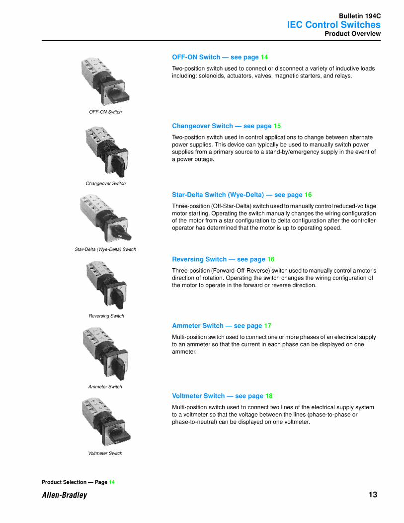
OFF-ON Switch — see page 14
Two-position switch used to connect or disconnect a variety of inductive loads
including: solenoids, actuators, valves, magnetic starters, and relays.
Changeover Switch — see page 15
Two-position switch used in control applications to change between alternate
power supplies. This device can typically be used to manually switch power
supplies from a primary source to a stand-by/emergency supply in the event of
a power outage.
Star-Delta Switch (Wye-Delta) — see page 16
Three-position (Off-Star-Delta) switch used to manually control reduced-voltage
motor starting. Operating the switch manually changes the wiring configuration
of the motor from a star configuration to delta configuration after the controller
operator has determined that the motor is up to operating speed.
Reversing Switch — see page 16
Three-position (Forward-Off-Reverse) switch used to manually control a motor’s
direction of rotation. Operating the switch changes the wiring configuration of
the motor to operate in the forward or reverse direction.
Ammeter Switch — see page 17
Multi-position switch used to connect one or more phases of an electrical supply
to an ammeter so that the current in each phase can be displayed on one
ammeter.
Voltmeter Switch — see page 18
Multi-position switch used to connect two lines of the electrical supply system
to a voltmeter so that the voltage between the lines (phase-to-phase or
phase-to-neutral) can be displayed on one voltmeter.
OFF-ON Switch
Changeover Switch
Star-Delta (Wye-Delta) Switch
Reversing Switch
Ammeter Switch
Voltmeter Switch
Product Selection — Page 14
Bulletin 194C
IEC Control Switches
14
Product Selection
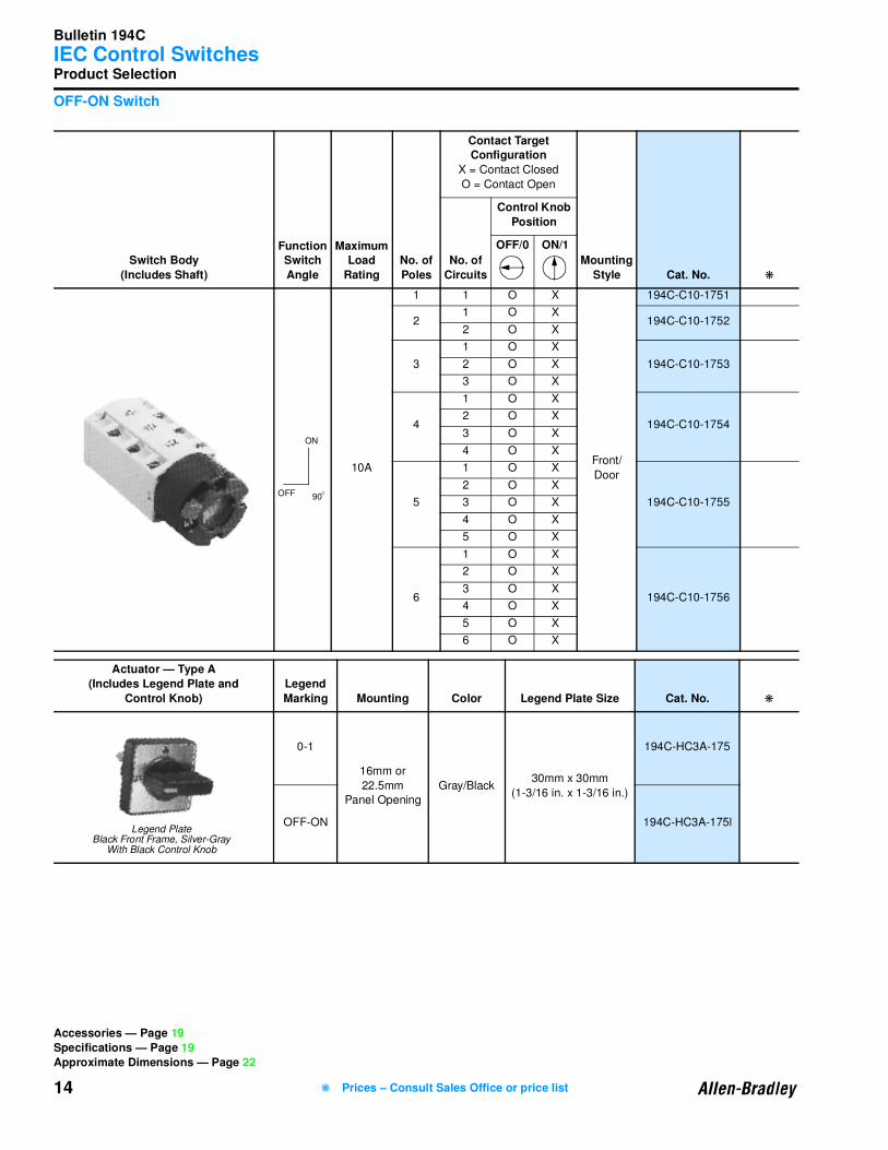
OFF-ON Switch
Switch Body
(Includes Shaft)
Function Switch
Angle
MaximumLoad
Rating
No. of
Poles
Contact Target Configuration
X = Contact Closed
O = Contact Open
Mounting
Style Cat. No. ❋
No. of
Circuits
Control Knob
Position
OFF/0 ON/1
10A
1 1 O X
Front/
Door
194C-C10-1751
21 O X
194C-C10-17522 O X
3
1 O X
194C-C10-17532 O X
3 O X
4
1 O X
194C-C10-17542 O X
3 O X
4 O X
5
1 O X
194C-C10-1755
2 O X
3 O X
4 O X
5 O X
6
1 O X
194C-C10-1756
2 O X
3 O X
4 O X
5 O X
6 O X
Actuator — Type A
(Includes Legend Plate and
Control Knob)
Legend
Marking Mounting Color Legend Plate Size Cat. No. ❋
0-1
16mm or
22.5mm
Panel Opening
Gray/Black30mm x 30mm
(1-3/16 in. x 1-3/16 in.)
194C-HC3A-175
OFF-ON 194C-HC3A-175l
90
ON
OFF O
Legend PlateBlack Front Frame, Silver-Gray
With Black Control Knob
Accessories — Page 19
Specifications — Page 19
Approximate Dimensions — Page 22
❋ Prices – Consult Sales Office or price list
Bulletin 194C
IEC Control Switches
15
Product Selection, Continued
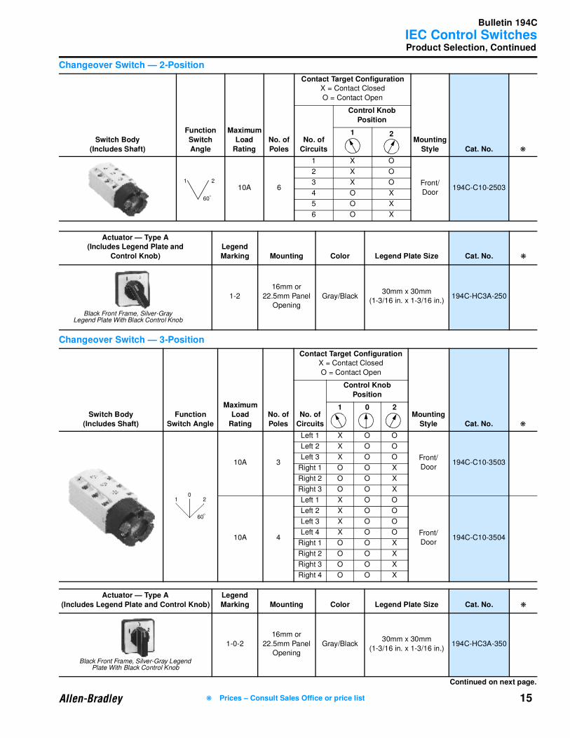
Changeover Switch — 2-Position
Changeover Switch — 3-Position
Switch Body
(Includes Shaft)
Function
Switch
Angle
Maximum
Load
Rating
No. of
Poles
Contact Target ConfigurationX = Contact Closed
O = Contact Open
Mounting
Style Cat. No. ❋
No. of
Circuits
Control Knob
Position
1 2
10A 6
1 X O
Front/
Door194C-C10-2503
2 X O
3 X O
4 O X
5 O X
6 O X
Actuator — Type A(Includes Legend Plate and
Control Knob)
Legend
Marking Mounting Color Legend Plate Size Cat. No. ❋
1-2
16mm or
22.5mm Panel
Opening
Gray/Black30mm x 30mm
(1-3/16 in. x 1-3/16 in.)194C-HC3A-250
Switch Body
(Includes Shaft)
Function
Switch Angle
Maximum
Load
Rating
No. of
Poles
Contact Target ConfigurationX = Contact Closed
O = Contact Open
Mounting
Style Cat. No. ❋
No. of
Circuits
Control Knob
Position
1 0 2
10A 3
Left 1 X O O
Front/
Door194C-C10-3503
Left 2 X O O
Left 3 X O O
Right 1 O O X
Right 2 O O X
Right 3 O O X
10A 4
Left 1 X O O
Front/
Door194C-C10-3504
Left 2 X O O
Left 3 X O O
Left 4 X O O
Right 1 O O X
Right 2 O O X
Right 3 O O X
Right 4 O O X
Actuator — Type A
(Includes Legend Plate and Control Knob)
Legend
Marking Mounting Color Legend Plate Size Cat. No. ❋
1-0-2
16mm or
22.5mm Panel
Opening
Gray/Black30mm x 30mm
(1-3/16 in. x 1-3/16 in.)194C-HC3A-350
60
1 2
O
Black Front Frame, Silver-Gray Legend Plate With Black Control Knob
60
1 20
O
Continued on next page.
Black Front Frame, Silver-Gray Legend Plate With Black Control Knob
❋ Prices – Consult Sales Office or price list

Bulletin 194C
IEC Control Switches
16
Product Selection, Continued
Star-Delta Switch (Wye-Delta)
Reversing Switch
Switch Body
(Includes Shaft)
Function
Switch Angle
Maximum
Load
Rating
Contact Target ConfigurationX = Contact Closed
O = Contact Open
Mounting
Style Cat. No. ❋
No. of
Circuits
Control Knob Position
0 Y ∆
10A
1 O X X
Front/
Door194C-C10-7503
2 O O X
3 O X O
4 O X O
5 O O X
6 O O X
7 O X X
8 O X X
Actuator — Type A
(Includes Legend Plate and Control Knob)
LegendMarking Mounting Color Legend Plate Size Cat. No. ❋
0-Y-∆
16mm or
22.5mm
Panel
Opening
Gray/Black30mm x 30mm
(1-3/16 in. x 1-3/16 in.)194C-HC3A-750
Switch Body
(Includes Shaft)
Function
Switch Angle
Maximum
Load
Rating
Contact Target ConfigurationX = Contact Closed
O = Contact Open
Mounting
Style Cat. No. ❋
No. of
Circuits
Control Knob Position
1 0 2
10A
1 O O X
Front/
Door194C-C10-7543
2 X O O
3 X O O
4 O O X
5 X O X
Actuator — Type A
(Includes Legend Plate and Control Knob) Legend Marking Mounting Color Legend Plate Size Cat. No. ❋
1-0-2
16mm or
22.5mm
Panel
Opening
Gray/Black30mm x 30mm
(1-3/16 in. x 1-3/16 in.)194C-HC3A-350
60
O Y
O
Black Front Frame, Silver-Gray Legend Plate With Black Control Knob
60
021
O
Black Front Frame, Silver-Gray Legend Plate With Black Control Knob
Accessories — Page 19
Specifications — Page 19
Approximate Dimensions — Page 22
❋ Prices – Consult Sales Office or price list

Bulletin 194C
IEC Control Switches
17
Product Selection, Continued
Ammeter Switch — 3∅ with Ground
Ammeter Switch — 3∅ with Neutral
Switch Body
(Includes Shaft)
Function Switch
Angle
Maximum
Load
Rating
Contact Target ConfigurationX = Contact Closed
O = Contact Open
Mounting
Style Cat. No. ❋
No. of
Circuits
Control Knob Position
0 1 2 3
10A
1 O X O O
Front/
Door194C-C10-8751
2 O O O X
3 X O O X
4 X O X O
5 O O O O
6 O O X O
7 X X O X
10A
1 X X O X
Front/
Door194C-C10-8752
2 O O X O
3 O X O O
4 O O O X
5 X O X X
6 X X X O
7 O X O O
8 O O O X
9 O O X O
Switch Body(Includes Shaft)
Function Switch Angle
Maximum
LoadRating
Contact Target ConfigurationX = Contact Closed
O = Contact Open
Mounting Style Cat. No. ❋
No. of Circuits
Control Knob Position
1 2 3 4
10A
1 X O O O
Front/
Door194C-C10-8761
2 O O X O
3 O X O O
4 O O O X
5 X O X X
6 X X X O
7 O X X X
8 X X O X
Actuator — Type A
(Includes Legend Plate and Control Knob)
LegendMarking Mounting Color Legend Plate Size Cat. No. ❋
0-1-2-3
16mm or
22.5mm
Panel Opening
Gray/Black30mm x 30mm
(1-3/16 in. x 1-3/16 in.)194C-HC3A-875
1-2-3-4
16mm or
22.5mm
Panel Opening
Gray/Black30mm x 30mm
(1-3/16 in. x 1-3/16 in.)194C-HC3A-876
90
0
1
2
3
O
90
4
3
2
1
O
Black Front Frame, Silver-Gray Legend Plate With Black Control Knob
Accessories — Page 19
Specifications — Page 19
Approximate Dimensions — Page 22 Continued on next page.
❋ Prices – Consult Sales Office or price list
Bulletin 194C
IEC Control Switches
18 ❋ Prices – Consult Sales Office or price list
Product Selection, Continued
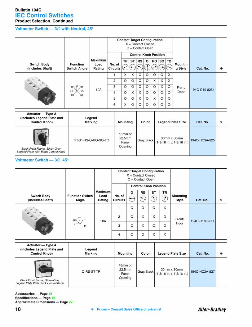
Voltmeter Switch — 3∅ with Neutral, 45°
Voltmeter Switch — 3∅, 45°
Switch Body(Includes Shaft)
Function Switch Angle
Maximum
LoadRating
Contact Target ConfigurationX = Contact Closed
O = Contact Open
Mounting Style Cat. No. ❋
No. of Circuits
Control Knob Position
TR ST RS O RO SO TO
10A
1 X X O O O O X
Front/
Door194C-C10-8251
2 O O O O X X X
3 O O O O O X O
4 O X X O O O O
5 O O X O X O O
6 X O O O O O O
Actuator — Type A
(Includes Legend Plate and
Control Knob)
Legend
Marking Mounting Color Legend Plate Size Cat. No. ❋
TR-ST-RS-O-RO-SO-TO
16mm or
22.5mm
Panel
Opening
Gray/Black30mm x 30mm
(1-3/16 in. x 1-3/16 in.)194C-HC3A-825
Switch Body
(Includes Shaft)
Function Switch
Angle
MaximumLoad
Rating
Contact Target Configuration
X = Contact Closed
O = Contact Open
Mounting
Style Cat. No. ❋
No. of
Circuits
Control Knob Position
O RS ST TR
10A
1 O O O X
Front/
Door194C-C10-8271
2 O X X O
3 O X O O
4 O O X X
Actuator — Type A
(Includes Legend Plate and
Control Knob)
Legend
Marking Mounting Color Legend Plate Size Cat. No. ❋
O-RS-ST-TR
16mm or
22.5mm
Panel
Opening
Gray/Black30mm x 30mm
(1-3/16 in. x 1-3/16 in.)194C-HC3A-827
RSO
RO
SOST
TOTR
Black Front Frame, Silver-Gray Legend Plate With Black Control Knob
0
RSST TR
45O
Black Front Frame, Silver-Gray Legend Plate With Black Control Knob
Accessories — Page 19
Specifications — Page 19
Approximate Dimensions — Page 22

Bulletin 194C
IEC Control Switches
19
Accessories/Specifications
Electrical Ratings
➊ See conformity to standards listed on page 12.
Switch Size Description
Pkg.
Qty. Cat. No. ❋
10A
Replacement Black Control Knob 10 194C-G3381
Use Bulletin 800E Legends, page 11-299 in the
Industrial Controls catalog.
– –
– –
– Locking Ring Wrench 1 800E-AW2
Performance Data 10A
IEC Applications
Rated voltage Ue ➊ IEC 947-5 VDE/BS
SEV max.
CEE 24/NEMKO
[V]
[V]
[V]
440
380
380
Principal switching characteristics
Isolating conditions acc. to VDE fulfilled up to
Rated impulse voltage Uimp
[V]
[kV]
250
4
Thermal rated current Ith ➊ 40°CIEC 947-5 VDE/BS
SEV 380V
[A]
[A]
10
10
AC-21 Switching resistive loads with slight
overload
IEC 947-5 VDE/BS
CEE24
NEMKO
[A]
[A]
[A]
10
4
6
AC-1 Non-inductive or slightly inductive loads SEV 380V [A] 10
AC-22 Switching mixed resistive and inductive
loads with slight overloadIEC 947-5 VDE/BS 220…500V [A] 10
AC-15 Switching of inductive drives, motors,
valves and electromagnets
IEC 947-5 220…240V
380…440V
[A]
[A]
2.5
1.5
Product Selection — Page 14 Continued on next page.
❋ Prices – Consult Sales Office or price list
Bulletin 194C
IEC Control Switches
20
Specifications, Continued
Electrical Ratings, Continued
➊ See conformity to standards listed on page 12.
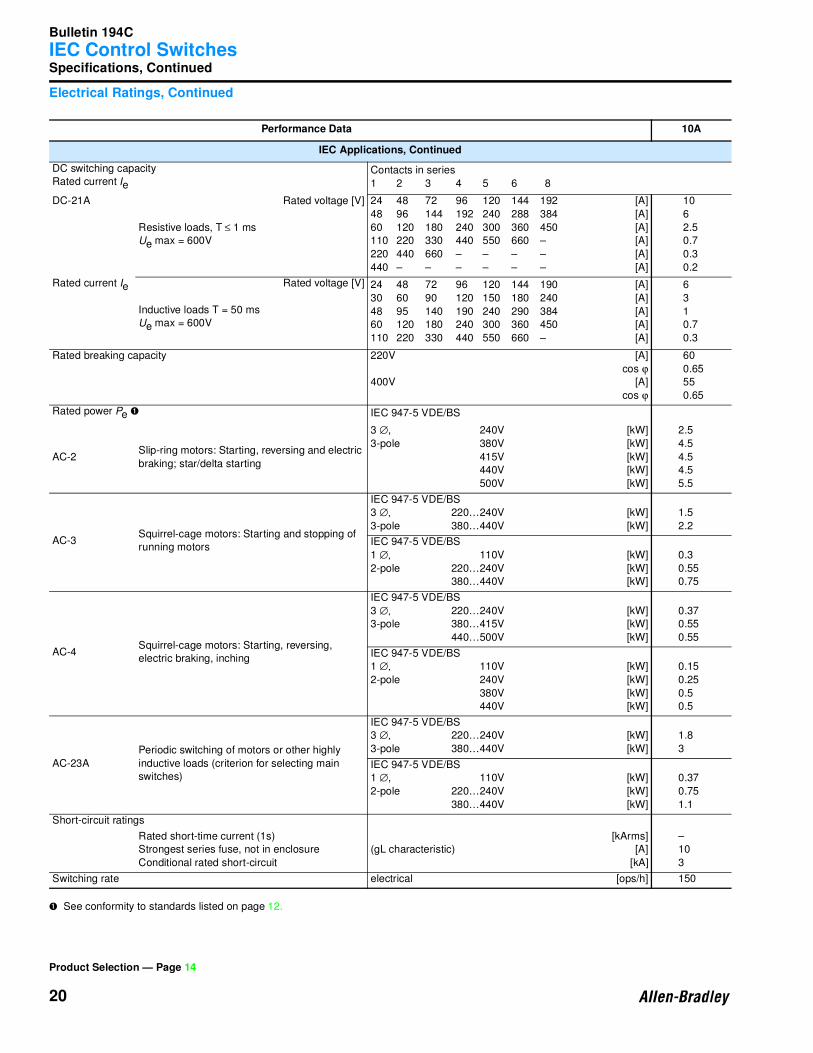
Performance Data 10A
IEC Applications, Continued
DC switching capacity
Rated current Ie
Contacts in series
1 2 3 4 5 6 8
DC-21A Rated voltage [V]
Resistive loads, T ≤ 1 ms
Ue max = 600V
24 48 72 96 120 144 192
48 96 144 192 240 288 384
60 120 180 240 300 360 450
110 220 330 440 550 660 –
220 440 660 – – – –
440 – – – – – –
[A]
[A]
[A]
[A]
[A]
[A]
10
6
2.5
0.7
0.3
0.2
Rated current Ie Rated voltage [V]
Inductive loads T = 50 ms
Ue max = 600V
24 48 72 96 120 144 190
30 60 90 120 150 180 240
48 95 140 190 240 290 384
60 120 180 240 300 360 450
110 220 330 440 550 660 –
[A]
[A]
[A]
[A]
[A]
6
3
1
0.7
0.3
Rated breaking capacity 220V
400V
[A]
cos ϕ
[A]
cos ϕ
60
0.65
55
0.65
Rated power Pe ➊ IEC 947-5 VDE/BS
AC-2Slip-ring motors: Starting, reversing and electric
braking; star/delta starting
3 ∅, 240V
3-pole 380V
415V
440V
500V
[kW]
[kW]
[kW]
[kW]
[kW]
2.5
4.5
4.5
4.5
5.5
AC-3Squirrel-cage motors: Starting and stopping of
running motors
IEC 947-5 VDE/BS
3 ∅, 220…240V
3-pole 380…440V
[kW]
[kW]
1.5
2.2
IEC 947-5 VDE/BS
1 ∅, 110V
2-pole 220…240V
380…440V
[kW]
[kW]
[kW]
0.3
0.55
0.75
AC-4Squirrel-cage motors: Starting, reversing,
electric braking, inching
IEC 947-5 VDE/BS
3 ∅, 220…240V
3-pole 380…415V
440…500V
[kW]
[kW]
[kW]
0.37
0.55
0.55
IEC 947-5 VDE/BS
1 ∅, 110V
2-pole 240V
380V
440V
[kW]
[kW]
[kW]
[kW]
0.15
0.25
0.5
0.5
AC-23A
Periodic switching of motors or other highly
inductive loads (criterion for selecting main
switches)
IEC 947-5 VDE/BS
3 ∅, 220…240V
3-pole 380…440V
[kW]
[kW]
1.8
3
IEC 947-5 VDE/BS
1 ∅, 110V
2-pole 220…240V
380…440V
[kW]
[kW]
[kW]
0.37
0.75
1.1
Short-circuit ratings
Rated short-time current (1s)
Strongest series fuse, not in enclosure
Conditional rated short-circuit
(gL characteristic)
[kArms]
[A]
[kA]
–
10
3
Switching rate electrical [ops/h] 150
Product Selection — Page 14
Bulletin 194C
IEC Control Switches
21
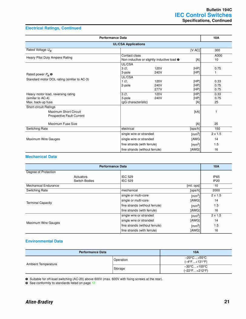
Specifications, Continued
Electrical Ratings, Continued
Mechanical Data
Environmental Data
➊ Suitable for off-load switching (AC-20) above 600V (max. 600V with fixing screws at the rear).
➋ See conformity to standards listed on page 12.
Performance Data 10A
UL/CSA Applications
Rated Voltage Ue [V AC] 300
Heavy Pilot Duty Ampere RatingContact class
Non-inductive or slightly inductive load ➊ [A]
A300
10
Rated power Pe ➋
Standard motor DOL rating (similar to AC-3)
UL/CSA
3 ∅, 120V
3-pole 240V
[HP]
[HP]
0.75
1
UL/CSA
1 ∅, 120V
2-pole 240V
277V
[HP]
[HP]
[HP]
0.33
0.75
0.75
Heavy motor load, reversing rating
(similar to AC-4)
Max. back-up fuse
3 ∅, 120V
3-pole 240V
(gG characteristic)
[HP]
[HP]
[A]
0.33
0.75
25
Short-circuit Ratings
Maximum Short Circuit
Prospective Fault Current
Maximum Fuse Size
[kA]
[A]
1
25
Switching Rate electrical [ops/h] 150
Maximum Wire Gauges
single wire or stranded [mm2] 2 x 1.5
single wire or stranded [AWG 14
fine strands (with ferrule) [mm2] 1.5
fine strands (without ferrule) [AWG] 16
Performance Data 10A
Degree of Protection
Actuators
Switch Bodies
IEC 529
IEC 529
IP65
IP20
Mechanical Endurance [mil. ops] 10
Switching Rate mechanical [ops/h] 2000
Terminal Capacity
single or multi-core [mm2] 2 x 1.5
single or multi-core [AWG] 14
fine strands (without ferrule) [mm2] 1.5
fine strands (with ferrule) [AWG] 16
Maximum Wire Gauges
single wire or stranded [mm2] 2 x 1.5
single wire or stranded [AWG] 14
fine strands (without ferrule) [mm2] 1.5
fine strands (with ferrule) [AWG] 16
Performance Data 10A
Ambient Temperature
Operation–20°C…+55°C
(–4°F…+131°F)
Storage–30°C…+100°C
(–22°F…+212°F)
Bulletin 194C
IEC Control Switches
22
Approximate Dimensions
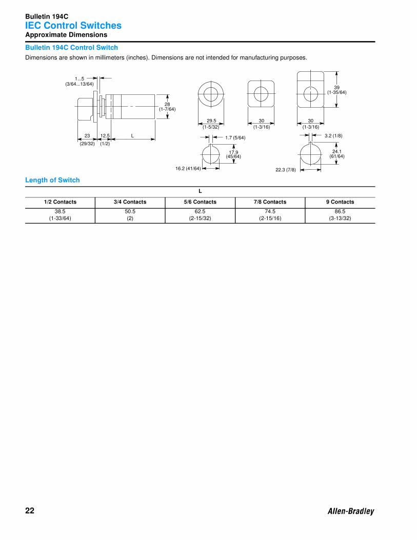
Bulletin 194C Control Switch
Dimensions are shown in millimeters (inches). Dimensions are not intended for manufacturing purposes.
Length of Switch
L
1/2 Contacts 3/4 Contacts 5/6 Contacts 7/8 Contacts 9 Contacts
38.5
(1-33/64)
50.5
(2)
62.5
(2-15/32)
74.5
(2-15/16)
86.5
(3-13/32)
1...5(3/64...13/64)
23
(29/32)
12.5
(1/2)
L
28(1-7/64)
29.5
(1-5/32)
30
(1-3/16)
30
(1-3/16)
39(1-35/64)
1.7 (5/64)
17.9(45/64)
16.2 (41/64)
3.2 (1/8)
24.1(61/64)
22.3 (7/8)
Bulletin 194C
IEC Control Switches
23
Notes
Product Selection — Page 14
Bulletin 194E
IEC Load Switches
24
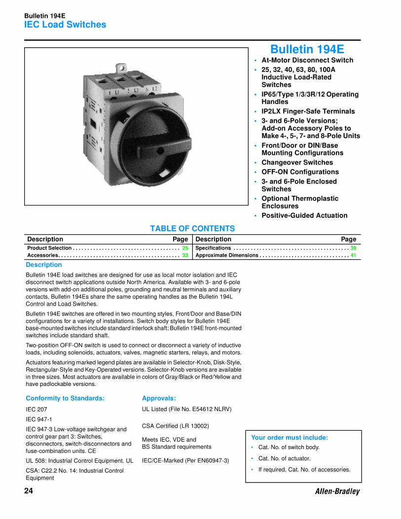
Bulletin 194E• At-Motor Disconnect Switch
• 25, 32, 40, 63, 80, 100A Inductive Load-Rated Switches
• IP65/Type 1/3/3R/12 Operating Handles
• IP2LX Finger-Safe Terminals
• 3- and 6-Pole Versions;Add-on Accessory Poles to Make 4-, 5-, 7- and 8-Pole Units
• Front/Door or DIN/Base Mounting Configurations
• Changeover Switches
• OFF-ON Configurations
• 3- and 6-Pole Enclosed Switches
• Optional Thermoplastic Enclosures
• Positive-Guided Actuation
TABLE OF CONTENTS
Description Page Description Page
Product Selection . . . . . . . . . . . . . . . . . . . . . . . . . . . . . . . . . . . . . 25
Accessories. . . . . . . . . . . . . . . . . . . . . . . . . . . . . . . . . . . . . . . . . . 33
Specifications . . . . . . . . . . . . . . . . . . . . . . . . . . . . . . . . . . . . . . . . 39
Approximate Dimensions . . . . . . . . . . . . . . . . . . . . . . . . . . . . . . . 41
Description
Bulletin 194E load switches are designed for use as local motor isolation and IEC
disconnect switch applications outside North America. Available with 3- and 6-pole
versions with add-on additional poles, grounding and neutral terminals and auxiliary
contacts, Bulletin 194Es share the same operating handles as the Bulletin 194L
Control and Load Switches.
Bulletin 194E switches are offered in two mounting styles, Front/Door and Base/DIN
configurations for a variety of installations. Switch body styles for Bulletin 194E
base-mounted switches include standard interlock shaft; Bulletin 194E front-mounted
switches include standard shaft.
Two-position OFF-ON switch is used to connect or disconnect a variety of inductive
loads, including solenoids, actuators, valves, magnetic starters, relays, and motors.
Actuators featuring marked legend plates are available in Selector-Knob, Disk-Style,
Rectangular-Style and Key-Operated versions. Selector-Knob versions are available
in three sizes. Most actuators are available in colors of Gray/Black or Red/Yellow and
have padlockable versions.
Conformity to Standards: Approvals:
IEC 207 UL Listed (File No. E54612 NLRV)
IEC 947-1
IEC 947-3 Low-voltage switchgear and
control gear part 3: Switches,
disconnectors, switch-disconnectors and
fuse-combination units. CE
CSA Certified (LR 13002)
Meets IEC, VDE and
BS Standard requirements
Your order must include:
• Cat. No. of switch body.
• Cat. No. of actuator.
• If required, Cat. No. of accessories.
UL 508: Industrial Control Equipment. UL IEC/CE-Marked (Per EN60947-3)
CSA: C22.2 No. 14: Industrial Control
Equipment
Bulletin 194E
IEC Load Switches
25
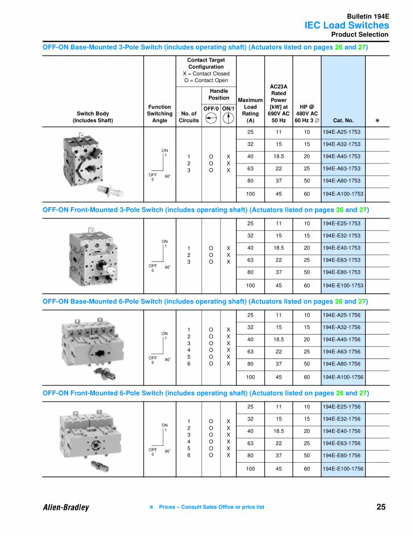
Product Selection
OFF-ON Base-Mounted 3-Pole Switch (includes operating shaft) (Actuators listed on pages 26 and 27)
OFF-ON Front-Mounted 3-Pole Switch (includes operating shaft) (Actuators listed on pages 26 and 27)
OFF-ON Base-Mounted 6-Pole Switch (includes operating shaft) (Actuators listed on pages 26 and 27)
OFF-ON Front-Mounted 6-Pole Switch (includes operating shaft) (Actuators listed on pages 26 and 27)
Switch Body
(Includes Shaft)
Function Switching
Angle
Contact Target
Configuration
X = Contact Closed
O = Contact Open
Maximum
Load Rating
(A)
AC23A Rated
Power
[kW] at 690V AC
50 Hz
HP @ 480V AC
60 Hz 3 ∅ Cat. No. ❋
No. of
Circuits
Handle
Position
OFF/0 ON/1
1
2
3
O
O
O
X
X
X
25 11 10 194E-A25-1753
32 15 15 194E-A32-1753
40 18.5 20 194E-A40-1753
63 22 25 194E-A63-1753
80 37 50 194E-A80-1753
100 45 60 194E-A100-1753
1
2
3
O
O
O
X
X
X
25 11 10 194E-E25-1753
32 15 15 194E-E32-1753
40 18.5 20 194E-E40-1753
63 22 25 194E-E63-1753
80 37 50 194E-E80-1753
100 45 60 194E-E100-1753
1
2
3
4
5
6
O
O
O
O
O
O
X
X
X
X
X
X
25 11 10 194E-A25-1756
32 15 15 194E-A32-1756
40 18.5 20 194E-A40-1756
63 22 25 194E-A63-1756
80 37 50 194E-A80-1756
100 45 60 194E-A100-1756
1
2
3
4
5
6
O
O
O
O
O
O
X
X
X
X
X
X
25 11 10 194E-E25-1756
32 15 15 194E-E32-1756
40 18.5 20 194E-E40-1756
63 22 25 194E-E63-1756
80 37 50 194E-E80-1756
100 45 60 194E-E100-1756
90
ON
OFF O
1
0
90
ON
OFF O
1
0
90
ON
OFF O
1
0
90
ON
OFF O
1
0
❋ Prices – Consult Sales Office or price list
Bulletin 194E
IEC Load Switches
26
Product Selection, Continued
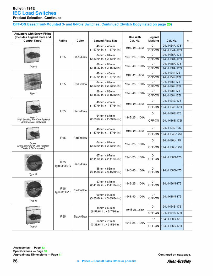
OFF-ON Base/Front-Mounted 3- and 6-Pole Switches, Continued (Switch Body listed on page 25)
Actuators with Screw Fixing(Includes Legend Plate and
Control Knob) Rating Color Legend Plate Size
Use With
Cat. No.
Legend
Marking Cat. No. ❋
IP65 Black/Gray
48mm x 48mm
(1-57/64 in. x 1-57/64 in.)194E-25…63A
0-1 194L-HE4A-175
OFF-ON 194L-HE4A-175I
64mm x 64mm
(2-33/64 in. x 2-33/64 in.)194E-25…100A
0-1 194L-HE6A-175
OFF-ON 194L-HE6A-175I
88mm x 88mm
(3-15/32 in. x 3-15/32 in.)194E-40…100A
0-1 194L-HE8A-175
OFF-ON 194L-HE8A-175I
IP65 Red/Yellow
48mm x 48mm
(1-57/64 in. x 1-57/64 in.)194E-25…63A
0-1 194L-HE4I-175
OFF-ON 194L-HE4I-175I
64mm x 64mm
(2-33/64 in. x 2-33/64 in.)194E-25…100A
0-1 194L-HE6I-175
OFF-ON 194L-HE6I-175I
88mm x 88mm
(3-15/32 in. x 3-15/32 in.)194E-40…100A
0-1 194L-HE8I-175
OFF-ON 194L-HE8I-175I
IP65 Black/Gray
48mm x 48mm
(1-57/64 in. x 1-57/64 in.)194E-25…63A
0-1 194L-HE4E-175
OFF-ON 194L-HE4E-175I
64mm x 64mm
(2-33/64 in. x 2-33/64 in.)194E-25…100A
0-1 194L-HE6E-175
OFF-ON 194L-HE6E-175I
IP65 Red/Yellow
48mm x 48mm
(1-57/64 in. x 1-57/64 in.)194E-25…63A
0-1 194L-HE4L-175
OFF-ON 194L-HE4L-175I
64mm x 64mm
(2-33/64 in. x 2-33/64 in.)194E-25…100A
0-1 194L-HE6L-175
OFF-ON 194L-HE6L-175I
IP65
Type 3/3R/12Black/Gray
67mm x 67mm
(2-41/64 in. x 2-41/64 in.)194E-25…100A
0-1
OFF-ON194L-HE6G-175
88mm x 88mm
(3-15/32 in. x 3-15/32 in.)194E-40…100A
0-1
OFF-ON194L-HE8G-175
IP65
Type 3/3R/12Red/Yellow
67mm x 67mm
(2-41/64 in. x 2-41/64 in.)194E-25…100A
0-1
OFF-ON194L-HE6N-175
90mm x 90mm
(3-35/64 in. x 3-35/64 in.)194E-40…100A
0-1
OFF-ON194L-HE8N-175
IP65 Black/Gray
48mm x 62mm
(1-57/64 in. x 2-7/16 in.)194E-25…63A
0-1 194L-HE4S-175
OFF-ON 194L-HE4S-175I
64mm x 78mm
(2-33/64 in. x 3-5/64 in.)194E-25…100A
0-1 194L-HE6S-175
OFF-ON 194L-HE6S-175I
Accessories — Page 33
Specifications — Page 39Approximate Dimensions — Page 41 Continued on next page.
Type A
Type I
Type EWith Locking For One Padlock
(Padlock Not Included)
Type LWith Locking For One Padlock
(Padlock Not Included)
Type G
Type N
Type S
❋ Prices – Consult Sales Office or price list
Bulletin 194E
IEC Load Switches
27
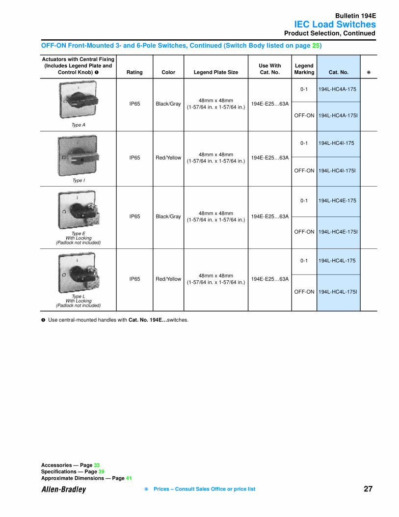
Product Selection, Continued
OFF-ON Front-Mounted 3- and 6-Pole Switches, Continued (Switch Body listed on page 25)
➊ Use central-mounted handles with Cat. No. 194E…switches.
Actuators with Central Fixing(Includes Legend Plate and
Control Knob) ➊ Rating Color Legend Plate Size
Use With
Cat. No.
Legend
Marking Cat. No. ❋
IP65 Black/Gray48mm x 48mm
(1-57/64 in. x 1-57/64 in.)194E-E25…63A
0-1 194L-HC4A-175
OFF-ON 194L-HC4A-175I
IP65 Red/Yellow48mm x 48mm
(1-57/64 in. x 1-57/64 in.)194E-E25…63A
0-1 194L-HC4I-175
OFF-ON 194L-HC4I-175I
IP65 Black/Gray48mm x 48mm
(1-57/64 in. x 1-57/64 in.)194E-E25…63A
0-1 194L-HC4E-175
OFF-ON 194L-HC4E-175I
IP65 Red/Yellow48mm x 48mm
(1-57/64 in. x 1-57/64 in.)194E-E25…63A
0-1 194L-HC4L-175
OFF-ON 194L-HC4L-175I
Accessories — Page 33Specifications — Page 39
Approximate Dimensions — Page 41
Type A
Type I
Type EWith Locking
(Padlock not included)
Type LWith Locking
(Padlock not included)
❋ Prices – Consult Sales Office or price list
Bulletin 194E
IEC Load Switches
28
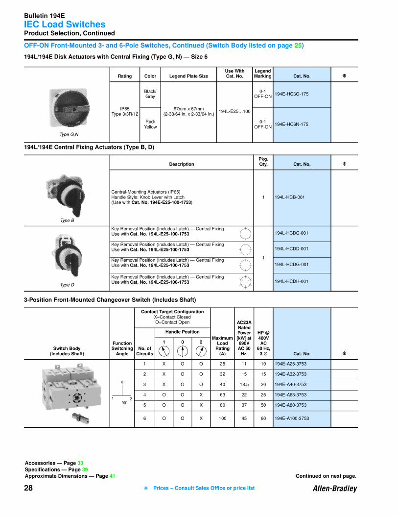
Product Selection, Continued
OFF-ON Front-Mounted 3- and 6-Pole Switches, Continued (Switch Body listed on page 25)
194L/194E Disk Actuators with Central Fixing (Type G, N) — Size 6
194L/194E Central Fixing Actuators (Type B, D)
3-Position Front-Mounted Changeover Switch (Includes Shaft)
Rating Color Legend Plate SizeUse With Cat. No.
Legend Marking Cat. No. ❋
IP65Type 3/3R/12
Black/Gray
67mm x 67mm(2-33/64 in. x 2-33/64 in.)
194L-E25…100
0-1OFF-ON
194E-HC6G-175
Red/Yellow
0-1OFF-ON
194E-HC6N-175
DescriptionPkg. Qty. Cat. No. ❋
Central-Mounting Actuators (IP65)Handle Style: Knob Lever with Latch(Use with Cat. No. 194E-E25-100-1753)
1 194L-HCB-001
Key Removal Position (Includes Latch) — Central FixingUse with Cat. No. 194L-E25-100-1753
1
194L-HCDC-001
Key Removal Position (Includes Latch) — Central FixingUse with Cat. No. 194L-E25-100-1753 194L-HCDD-001
Key Removal Position (Includes Latch) — Central FixingUse with Cat. No. 194L-E25-100-1753 194L-HCDG-001
Key Removal Position (Includes Latch) — Central FixingUse with Cat. No. 194L-E25-100-1753 194L-HCDH-001
Switch Body(Includes Shaft)
Function Switching
Angle
Contact Target ConfigurationX=Contact ClosedO=Contact Open
Maximum Load
Rating (A)
AC23A Rated Power [kW] at 690V AC 50
Hz.
HP @ 480V AC
60 Hz,3 ∅ Cat. No. ❋
No. of Circuits
Handle Position
1 0 2
1 X O O 25 11 10 194E-A25-3753
2 X O O 32 15 15 194E-A32-3753
3 X O O 40 18.5 20 194E-A40-3753
4 O O X 63 22 25 194E-A63-3753
5 O O X 80 37 50 194E-A80-3753
6 O O X 100 45 60 194E-A100-3753
Type G,N
Type B
Type D
90
0
21O
Accessories — Page 33
Specifications — Page 39Approximate Dimensions — Page 41 Continued on next page.
❋ Prices – Consult Sales Office or price list
Bulletin 194E
IEC Load Switches
29
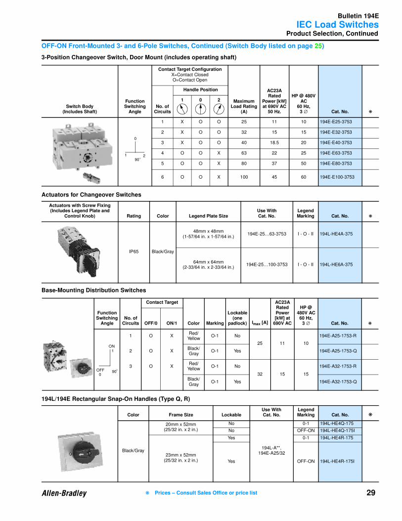
Product Selection, Continued
OFF-ON Front-Mounted 3- and 6-Pole Switches, Continued (Switch Body listed on page 25)
3-Position Changeover Switch, Door Mount (includes operating shaft)
Actuators for Changeover Switches
Base-Mounting Distribution Switches
194L/194E Rectangular Snap-On Handles (Type Q, R)
Switch Body(Includes Shaft)
Function Switching
Angle
Contact Target ConfigurationX=Contact ClosedO=Contact Open
Maximum Load Rating
(A)
AC23A Rated
Power [kW] at 690V AC
50 Hz.
HP @ 480V AC
60 Hz,3 ∅ Cat. No. ❋
No. of Circuits
Handle Position
1 0 2
1 X O O 25 11 10 194E-E25-3753
2 X O O 32 15 15 194E-E32-3753
3 X O O 40 18.5 20 194E-E40-3753
4 O O X 63 22 25 194E-E63-3753
5 O O X 80 37 50 194E-E80-3753
6 O O X 100 45 60 194E-E100-3753
Actuators with Screw Fixing (Includes Legend Plate and
Control Knob) Rating Color Legend Plate SizeUse With Cat. No.
Legend Marking Cat. No. ❋
IP65 Black/Gray
48mm x 48mm(1-57/64 in. x 1-57/64 in.)
194E-25…63-3753 I - O - II 194L-HE4A-375
64mm x 64mm(2-33/64 in. x 2-33/64 in.)
194E-25…100-3753 I - O - II 194L-HE6A-375
Function Switching
AngleNo. of
Circuits
Contact Target
Color Marking
Lockable (one
padlock) Imax [A]
AC23A Rated Power [kW] at
690V AC
HP @ 480V AC60 Hz,
3 ∅ Cat. No. ❋OFF/0 ON/1
1 O XRed/
YellowO-1 No
25 11 10
194E-A25-1753-R
2 O XBlack/Gray
O-1 Yes 194E-A25-1753-Q
3 O XRed/
YellowO-1 No
32 15 15
194E-A32-1753-R
Black/Gray
O-1 Yes 194E-A32-1753-Q
Color Frame Size LockableUse With Cat. No.
Legend Marking Cat. No. ❋
Black/Gray
20mm x 52mm(25/32 in. x 2 in.)
No
194L-A**,194E-A25/32
0-1 194L-HE4Q-175
No OFF-ON 194L-HE4Q-175I
23mm x 52mm(25/32 in. x 2 in.)
Yes 0-1 194L-HE4R-175
Yes OFF-ON 194L-HE4R-175I
90
0
21O
90
ON
OFF O
1
0
❋ Prices – Consult Sales Office or price list
Bulletin 194E
IEC Load Switches
30 ❋ Prices – Consult Sales Office or price list
Product Selection, Continued
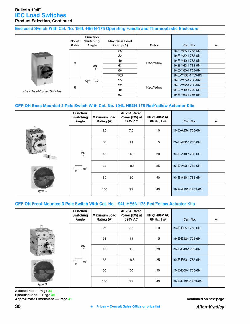
Enclosed Switch With Cat. No. 194L-HE6N-175 Operating Handle and Thermoplastic Enclosure
OFF-ON Base-Mounted 3-Pole Switch With Cat. No. 194L-HE6N-175 Red/Yellow Actuator Kits
OFF-ON Front-Mounted 3-Pole Switch With Cat. No. 194L-HE6N-175 Red/Yellow Actuator Kits
No. of
Poles
Function Switching
Angle
Maximum Load
Rating (A) Color Cat. No. ❋
3
25
Red/Yellow
194E-Y25-1753-6N
32 194E-Y32-1753-6N
40 194E-Y40-1753-6N
63 194E-Y63-1753-6N
80 194E-Y80-1753-6N
100 194E-Y100-1753-6N
6
25
Red/Yellow
194E-Y25-1756-6N
32 194E-Y32-1756-6N
40 194E-Y40-1756-6N
63 194E-Y63-1756-6N
Function Switching
Angle
Maximum Load
Rating (A)
AC23A Rated Power [kW] at
690V AC
HP @ 480V AC
60 Hz, 3 ∅ Cat. No. ❋
25 7.5 10 194E-A25-1753-6N
32 11 15 194E-A32-1753-6N
40 15 20 194E-A40-1753-6N
63 18.5 25 194E-A63-1753-6N
80 30 50 194E-A80-1753-6N
100 37 60 194E-A100-1753-6N
Function
Switching
Angle
Maximum Load
Rating (A)
AC23A Rated
Power [kW] at
690V AC
HP @ 480V AC
60 Hz, 3 ∅ Cat. No. ❋
25 7.5 10 194E-E25-1753-6N
32 11 15 194E-E32-1753-6N
40 15 20 194E-E40-1753-6N
63 18.5 25 194E-E63-1753-6N
80 30 50 194E-E80-1753-6N
100 37 60 194E-E100-1753-6N
Uses Base-Mounted Switches
90
ON
OFF O
1
0
Type G
90
ON
OFF O
1
0
Type G
90
ON
OFF O
1
0
Accessories — Page 33
Specifications — Page 39
Approximate Dimensions — Page 41 Continued on next page.
Bulletin 194E
IEC Load Switches
31
Product Selection, Continued
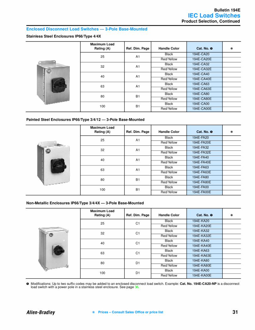
Enclosed Disconnect Load Switches — 3-Pole Base-Mounted
Stainless Steel Enclosures IP66/Type 4/4X
Painted Steel Enclosures IP66/Type 3/4/12 — 3-Pole Base-Mounted
Non-Metallic Enclosures IP66/Type 3/4/4X — 3-Pole Base-Mounted
➊ Modifications: Up to two suffix codes may be added to an enclosed disconnect load switch. Example: Cat. No. 194E-CA20-NP is a disconnect load switch with a power pole in a stainless steel enclosure. See page 36.
Maximum Load
Rating (A) Ref. Dim. Page Handle Color Cat. No. ➊ ❋
25 A1Black 194E-CA20
Red/Yellow 194E-CA20E
32 A1Black 194E-CA32
Red/Yellow 194E-CA32E
40 A1Black 194E-CA40
Red/Yellow 194E-CA40E
63 A1Black 194E-CA63
Red/Yellow 194E-CA63E
80 B1Black 194E-CA80
Red/Yellow 194E-CA80E
100 B1Black 194E-CA00
Red/Yellow 194E-CA00E
Maximum Load
Rating (A) Ref. Dim. Page Handle Color Cat. No. ➊ ❋
25 A1Black 194E-FA20
Red/Yellow 194E-FA20E
32 A1Black 194E-FA32
Red/Yellow 194E-FA32E
40 A1Black 194E-FA40
Red/Yellow 194E-FA40E
63 A1Black 194E-FA63
Red/Yellow 194E-FA63E
80 B1Black 194E-FA80
Red/Yellow 194E-FA80E
100 B1Black 194E-FA00
Red/Yellow 194E-FA00E
Maximum Load Rating (A) Ref. Dim. Page Handle Color Cat. No. ➊ ❋
25 C1Black 194E-KA20
Red/Yellow 194E-KA20E
32 C1Black 194E-KA32
Red/Yellow 194E-KA32E
40 C1Black 194E-KA40
Red/Yellow 194E-KA40E
63 C1Black 194E-KA63
Red/Yellow 194E-KA63E
80 D1Black 194E-KA80
Red/Yellow 194E-KA80E
100 D1Black 194E-KA00
Red/Yellow 194E-KA00E
❋ Prices – Consult Sales Office or price list

Bulletin 194E
IEC Load Switches
32 ❋ Prices – Consult Sales Office or price list
Product Selection, Continued
Enclosed Disconnect Load Switches — 3-Pole Base-Mounted, Continued
Metallic Enclosures IP54/Type 1 — 3-Pole
➊ Modifications: Up to two suffix codes may be added to an enclosed disconnect load switch. Example: Cat. No. 194E-CA20-NP is a disconnect load switch with a power pole in a stainless steel enclosure. See page 36.
Maximum Load
Rating (A) Ref. Dim. Page Handle Color Cat. No. ➊ ❋
25 A1Black 194E-AA20
Red/Yellow 194E-AA20E
32 A1Black 194E-AA32
Red/Yellow 194E-AA32E
40 A1Black 194E-AA40
Red/Yellow 194E-AA40E
63 A1Black 194E-AA63
Red/Yellow 194E-AA63E
80 B1Black 194E-AA80
Red/Yellow 194E-AA80E
100 B1Black 194E-AA00
Red/Yellow 194E-AA00E
ABS Thermoplastic Enclosure —
For High-Impact Applications No. of Poles Use With Cat. No. Cat. No. ❋
3…4 194E-25/32 194L-G3572
3…4 194E-40/63 194L-G3663
3…4 194E-80/100 194E-G3665
6 194E-25/32 194E-G3663
6 194E-40/63 194E-G3665
Noryl Thermoplastic Enclosures —For Corrosion-Prone Applications No. of Poles Switch Usage for Cat. No. Cat. No. ❋
3…4 194E-25/32 194L-G3576
3…4 194E-40/63 194L-G3664
3…4 194E-80/100 194E-G3666
6 194E-25/32 194E-G3664
6 194E-40/63 194E-G3666
Description Use With Enclosures Cat. No. Cat. No. ❋
Additional Earth/Ground and
Neutral Terminals — For Thermoplastic Enclosure
194L-G3663, G3664, G3665, G3666
(5 per package)194L-G3673
194L-G3572 and G3676
(5 per package)194L-G3653
Accessories — Page 33
Specifications — Page 39
Approximate Dimensions — Page 41
Accessories — Page 33Specifications — Page 39
Approximate Dimensions — Page 41
Bulletin 194E
IEC Load Switches
33
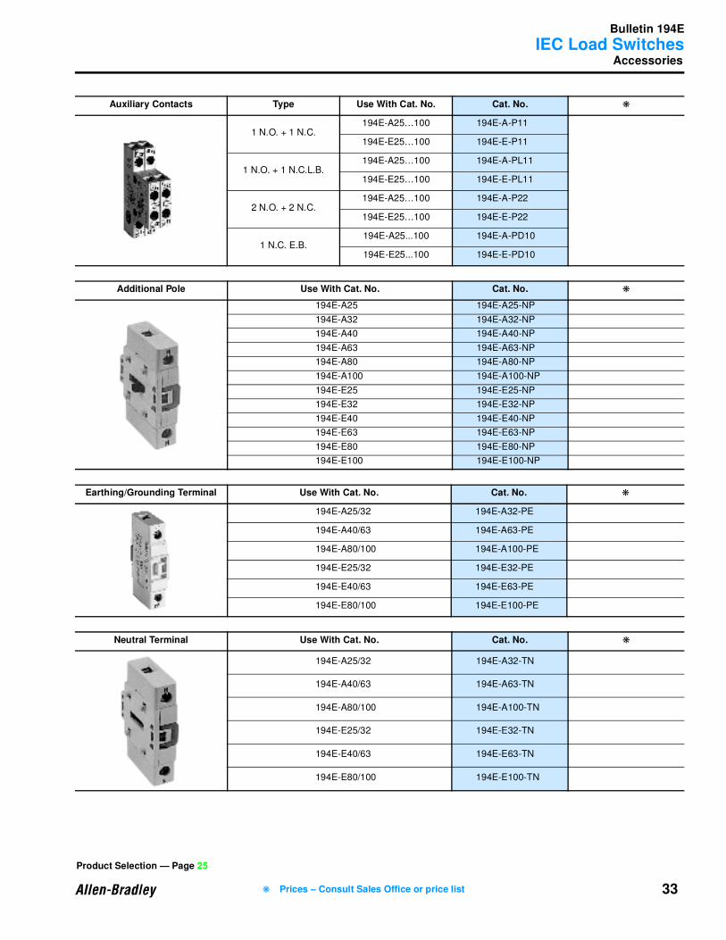
Accessories
Auxiliary Contacts Type Use With Cat. No. Cat. No. ❋
1 N.O. + 1 N.C.194E-A25…100 194E-A-P11
194E-E25…100 194E-E-P11
1 N.O. + 1 N.C.L.B.194E-A25…100 194E-A-PL11
194E-E25…100 194E-E-PL11
2 N.O. + 2 N.C.194E-A25…100 194E-A-P22
194E-E25…100 194E-E-P22
1 N.C. E.B.194E-A25...100 194E-A-PD10
194E-E25...100 194E-E-PD10
Additional Pole Use With Cat. No. Cat. No. ❋
194E-A25 194E-A25-NP
194E-A32 194E-A32-NP
194E-A40 194E-A40-NP
194E-A63 194E-A63-NP
194E-A80 194E-A80-NP
194E-A100 194E-A100-NP
194E-E25 194E-E25-NP
194E-E32 194E-E32-NP
194E-E40 194E-E40-NP
194E-E63 194E-E63-NP
194E-E80 194E-E80-NP
194E-E100 194E-E100-NP
Earthing/Grounding Terminal Use With Cat. No. Cat. No. ❋
194E-A25/32 194E-A32-PE
194E-A40/63 194E-A63-PE
194E-A80/100 194E-A100-PE
194E-E25/32 194E-E32-PE
194E-E40/63 194E-E63-PE
194E-E80/100 194E-E100-PE
Neutral Terminal Use With Cat. No. Cat. No. ❋
194E-A25/32 194E-A32-TN
194E-A40/63 194E-A63-TN
194E-A80/100 194E-A100-TN
194E-E25/32 194E-E32-TN
194E-E40/63 194E-E63-TN
194E-E80/100 194E-E100-TN
Product Selection — Page 25
❋ Prices – Consult Sales Office or price list
Bulletin 194E
IEC Load Switches
34
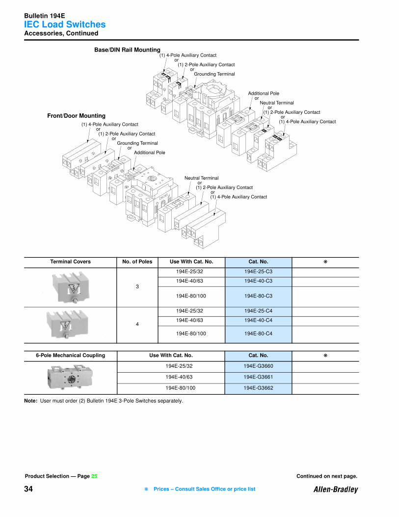
Accessories, Continued
Note: User must order (2) Bulletin 194E 3-Pole Switches separately.
Terminal Covers No. of Poles Use With Cat. No. Cat. No. ❋
3
194E-25/32 194E-25-C3
194E-40/63 194E-40-C3
194E-80/100 194E-80-C3
4
194E-25/32 194E-25-C4
194E-40/63 194E-40-C4
194E-80/100 194E-80-C4
6-Pole Mechanical Coupling Use With Cat. No. Cat. No. ❋
194E-25/32 194E-G3660
194E-40/63 194E-G3661
194E-80/100 194E-G3662
(1) 4-Pole Auxiliary Contact or
(1) 2-Pole Auxiliary Contact or Grounding Terminal
(1) 4-Pole Auxiliary Contact or
(1) 2-Pole Auxiliary Contact or Grounding Terminal or Additional Pole
Additional Pole or Neutral Terminal or
(1) 2-Pole Auxiliary Contact or
(1) 4-Pole Auxiliary Contact
Neutral Terminal or
(1) 2-Pole Auxiliary Contact or
(1) 4-Pole Auxiliary Contact
Base/DIN Rail Mounting
Front/Door Mounting
Product Selection — Page 25 Continued on next page.
❋ Prices – Consult Sales Office or price list
Bulletin 194E
IEC Load Switches
35
Accessories, Continued
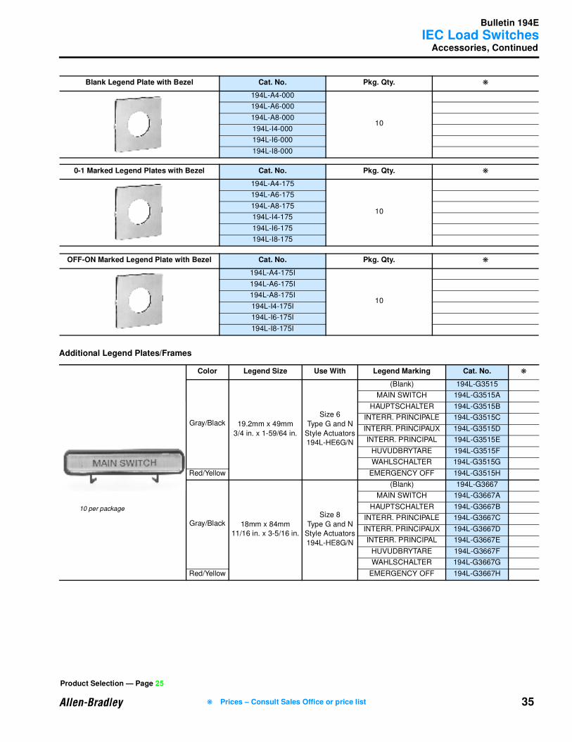
Additional Legend Plates/Frames
Blank Legend Plate with Bezel Cat. No. Pkg. Qty. ❋
194L-A4-000
10
194L-A6-000
194L-A8-000
194L-I4-000
194L-I6-000
194L-I8-000
0-1 Marked Legend Plates with Bezel Cat. No. Pkg. Qty. ❋
194L-A4-175
10
194L-A6-175
194L-A8-175
194L-I4-175
194L-I6-175
194L-I8-175
OFF-ON Marked Legend Plate with Bezel Cat. No. Pkg. Qty. ❋
194L-A4-175I
10
194L-A6-175I
194L-A8-175I
194L-I4-175I
194L-I6-175I
194L-I8-175I
Color Legend Size Use With Legend Marking Cat. No. ❋
Gray/Black 19.2mm x 49mm
3/4 in. x 1-59/64 in.
Size 6
Type G and N
Style Actuators
194L-HE6G/N
(Blank) 194L-G3515
MAIN SWITCH 194L-G3515A
HAUPTSCHALTER 194L-G3515B
INTERR. PRINCIPALE 194L-G3515C
INTERR. PRINCIPAUX 194L-G3515D
INTERR. PRINCIPAL 194L-G3515E
HUVUDBRYTARE 194L-G3515F
WAHLSCHALTER 194L-G3515G
Red/Yellow EMERGENCY OFF 194L-G3515H
Gray/Black 18mm x 84mm
11/16 in. x 3-5/16 in.
Size 8
Type G and N
Style Actuators
194L-HE8G/N
(Blank) 194L-G3667
MAIN SWITCH 194L-G3667A
HAUPTSCHALTER 194L-G3667B
INTERR. PRINCIPALE 194L-G3667C
INTERR. PRINCIPAUX 194L-G3667D
INTERR. PRINCIPAL 194L-G3667E
HUVUDBRYTARE 194L-G3667F
WAHLSCHALTER 194L-G3667G
Red/Yellow EMERGENCY OFF 194L-G3667H
Product Selection — Page 25
❋ Prices – Consult Sales Office or price list
10 per package
Bulletin 194E
IEC Load Switches
36
Accessories, Continued
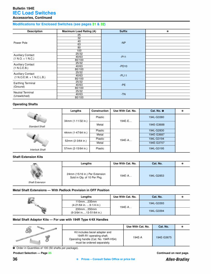
Modifications for Enclosed Switches (see pages 31 & 32)
Operating Shafts
Shaft Extension Kits
Metal Shaft Extensions — With Padlock Provision in OFF Position
Metal Shaft Adaptor Kits — For use with 194R Type 4/4X Handles
➊ Order in Quantities of 100 (50 shafts per package).
Description Maximum Load Rating (A) Suffix ❋
Power Pole
25
-NP
32406380100
Auxiliary Contact
(1 N.O. + 1 N.C.)
25/32-P1140/63
80/100
Auxiliary Contact
(1 N.C.E.B.)
25/32-PD1040/63
80/100
Auxiliary Contact
(1 N.O.E.M. + 1 N.C.L.B.)
25/32-PL1140/63
80/100
Earthing Terminal
(Ground)
25/32-PE40/63
80/100
Neutral Terminal
(Unswitched)
25/32-TN40/63
80/100
Lengths Construction Use With Cat. No. Cat. No. ➊ ❋
34mm (1-11/32 in.)
Plastic
194E-E…
194L-G3380
Metal 194E-G3688
44mm (1-47/64 in.)Plastic
194E-A…
194L-G2830
Metal 194E-G3687
52mm (2-3/64 in.)Plastic 194L-G3194
Metal 194E-G3707
57mm (2-15/64 in.) Plastic 194L-G3195
Lengths Use With Cat. No. Cat. No. ❋
24mm (15/16 in.) Per Extension
Sold in Qty. of 10 Per Pkg.194E-A… 194L-G2853
Lengths Use With Cat. No. Cat. No. ❋
110mm…235mm
(4-21/64 in. …9-1/4 in.)194E-A…
194L-G3393
230mm…350mm
(9-3/64 in.…13-51/64 in.)194L-G3394
Use With Cat. No. Cat. No. ❋
Kit includes bezel adapter and
194R-R1 operating shaft.
Operating handle (Cat. No. 194R-HS4)
must be ordered separately.
194E-A 194E-G3675
Standard Shaft
Interlock Shaft
Shaft Extension
Product Selection — Page 25 Continued on next page.
❋ Prices – Consult Sales Office or price list
Bulletin 194E
IEC Load Switches
37
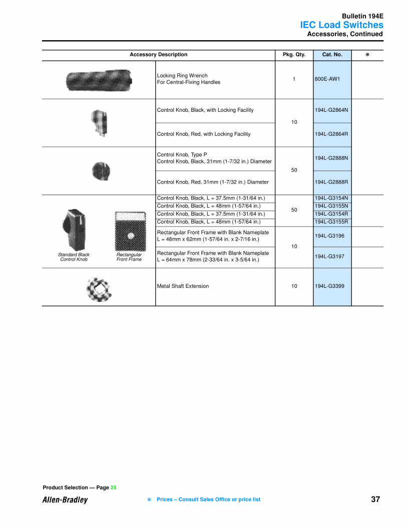
Accessories, Continued
Accessory Description Pkg. Qty. Cat. No. ❋
Locking Ring Wrench
For Central-Fixing Handles1 800E-AW1
Control Knob, Black, with Locking Facility
10
194L-G2864N
Control Knob, Red, with Locking Facility 194L-G2864R
Control Knob, Type P
Control Knob, Black, 31mm (1-7/32 in.) Diameter
50
194L-G2888N
Control Knob, Red, 31mm (1-7/32 in.) Diameter 194L-G2888R
Control Knob, Black, L = 37.5mm (1-31/64 in.)
50
194L-G3154N
Control Knob, Black, L = 48mm (1-57/64 in.) 194L-G3155N
Control Knob, Black, L = 37.5mm (1-31/64 in.) 194L-G3154R
Control Knob, Black, L = 48mm (1-57/64 in.) 194L-G3155R
Rectangular Front Frame with Blank Nameplate
L = 48mm x 62mm (1-57/64 in. x 2-7/16 in.)
10
194L-G3196
Rectangular Front Frame with Blank Nameplate
L = 64mm x 78mm (2-33/64 in. x 3-5/64 in.)194L-G3197
Metal Shaft Extension 10 194L-G3399
Standard BlackControl Knob
RectangularFront Frame
Product Selection — Page 25
❋ Prices – Consult Sales Office or price list
Bulletin 194E
IEC Load Switches
38
Accessories, Continued
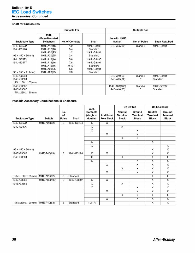
Shaft for Enclosures
Possible Accessory Combinations in Enclosure
Enclosure Type
Suitable For Suitable For
194L
(Base-Mounted
Switches) No. of Contacts Shaft
Use with 194E
Switch No. of Poles Shaft Required
194L-G3572
194L-G3576
(95 x 150 x 86mm)
194L-A12(16)
194L-A12(16)
194L-A20(25)
194L-A20(25)
1/2
3/4
1/2
3/4
194L-G3195
Standard
194L-G3194
Standard
194E-A25(32) 3 and 4 194L-G3194
194L G3573
194L-G3577
(95 x 150 x 111mm)
194L-A12(16)
194L-A12(16)
194L-A12(16)
194L-A20(25)
194L-A20(25)
5/6
7/8
9/10
5/6
7/8
194L-G3195
194L-G3194
Standard
194L-G3194
Standard
194E-C3663
194E-G3664
(125 x 180 x 105mm)
194E-A40(63)
194E-A25(32)
3 and 4
6
194L-G3194
Standard
194E-G3665
194E-G3666
(175 x 230 x 120mm)
194E-A80(100)
194E-A40(63)
3 and 4
6
194E-G3707
Standard
Enclosure Type Switch
No.
of
Poles Shaft
Aux. Contacts
(single or
double)
Additional
Pole Block
On Switch On Enclosure
Neutral
Terminal
Block
Ground
Terminal
Block
Neutral
Terminal
Block
Ground
Terminal
Block
194L-G3572 194E-A25(32) 3 194L-G3194 X X
194L-G3576 X X
X X
X X
X X
X X
X X
(95 x 150 x 86mm) X X
194E-G3663 194E-A40(63) 3 194L-G3194 X X X X
194E-G3664 X X X X
X X X X
X X X X
X X X X
X X X X
(125 x 180 x 105mm) 194E-A25(32) 6 Standard X X
194E-G3665 194E-A80(100) 3 194E-G3707 X X X X
194E-G3666 X X X X
X X X X
X X X X
X X X X
X X X X
(175 x 230 x 120mm) 194E-A40(63) 6 Standard 1L+1R X X

Bulletin 194E
IEC Load Switches
39
Specifications
Electrical Ratings
➊ See conformity to standards listed on page 24.
➋ Suitable also for SEV 500.
Performance Data 25A 32A 40A 63A 80A 100A Aux.
ContactsIEC Applications
Rated operational voltage (Ue): IEC ➊ [V] 690 690 690 690 690 690 690
Rated operational voltage (Ue): UL, CSA [V] 600 600 600 600 600 600 600
Rated insulation voltage (Ui): IEC/UL, CSA [V] 690/600 690/600 690/600 690/600 690/600 690/600 690/600
Rated impulse voltage (Uimp): UL, CSA [kV] 8 8 8 8 8 8 8
Test voltage, (Ui) 1 minute [kV] 2.5 2.5 2.5 2.5 2.5 2.5 2.5
Rated frequency [Hz] 50/60 50/60 50/60 50/60 50/60 50/60 50/60
Conventional free air thermal current Ith ➊ [A] 30 40 50 75 100 120 10 ➋
Conventional enclosed thermal current Ith ➊ [A] 25 32 40 63 80 100 6
Rated current Ie ➊
[A] 25 32 40 63 80 100 10
AC-1/ Non-inductive or only slightly
inductive loads
AC-21A Switching of resistive loads with
slight overload
Rated power Pe
230V [kW] 7.5 11 15 18.5 22 30 –AC-23A Occasional switching of 3∅ motors
and other highly inductive loads
(criterion for selecting main
switches)
400V [kW] 11 15 18.5 22 37 45 –
690V [kW] 11 15 18.5 22 37 45 –
AC-3Squirrel-cage motors; starting and
stopping of running motors
230V [kW] 5.5 7.5 11 15 18.5 22 –
400V [kW] 7.5 11 15 18.5 30 37 –
690V [kW] 7.5 11 15 18.5 22 22 –
Short circuit current
(co-ordination type 2)Rated conditional short-circuit current 400/415V [kA] 15 15 20 15 – – –
Maximum fuse rating of circuit (type g,G) [A] 25 25 50 63 80 100 –
Rated short-time current 1cw, 1s [A] 430 500 600 1300 1850 2500 –
Rated breaking capacity AC23A (cosϕ 0.45)
230V [A] 204 296 400 484 580 780 –
400V [A] 172 232 280 336 544 680 –
690V [A] 100 136 164 196 316 376 –
DC switching capacity
Rated current Ie
1 Pole
24V [A] 20 25 35 50 63 80
–
DC-21A For resistive loads,
T ≤ 1 ms
Ue max = 660V
48V [A] 16 20 28 40 50 63
110V [A] 6 8.5 12 15 20 23
220V [A] 2 3 3.8 5 6.5 7.5
440V [A] 0.55 0.75 1 1.2 1.5 1.8
600V [A] 0.3 0.4 0.5 0.6 0.7 0.8
2-Poles
in
series
24V [A] 25 32 40 63 80 100
–
48V [A] 20 25 35 50 63 80
110V [A] 14 17 24 34 44 53
220V [A] 5.5 7.5 12 14.5 18 22.5
440V [A] 1.7 2.5 3.5 4.5 5.5 6.8
600V [A] 1 1.5 2 2.5 3 3.5
3 Poles
in
series
24V [A] 25 32 40 63 80 100
–
48V [A] 25 32 40 63 80 100
110V [A] 18 23 32 45 56 70
220V [A] 10.5 13 19 24 30 37
440V [A] 3.8 5.5 7.5 9 11 13
600V [A] 2.5 3.5 4.5 5.5 6 8
Rated power Pe
DC-23A, DC-3, DC-5
3 Poles
in
series
24V [kW] 0.384 0.48 0.672 0.96 1.2 1.512
–
48V [kW] 0.528 0.768 1.056 1.44 1.824 2.256
For inductive loads,
T ≤ 15 ms
110V [kW] 0.77 1.045 1.65 1.87 2.31 2.86
220V [kW] 0.88 1.1 1.65 1.98 2.464 3.08
440V [kW] 0.704 0.88 1.32 1.54 1.804 2.2
600V [kW] 0.6 0.78 1.02 1.2 1.5 1.8
Product Selection — Page 25 Continued on next page.
Bulletin 194E
IEC Load Switches
40
Specifications, Continued
Electrical Ratings, Continued
Mechanical Data
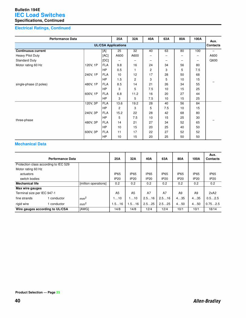
Performance Data 25A 32A 40A 63A 80A 100AAux.
ContactsUL/CSA Applications
Continuous current [A] 25 32 40 63 80 100 –
Heavy Pilot Duty [AC] A600 A600 – – – – A600
Standard Duty [DC] – – – – – – Q600
Motor rating 60 Hz 120V, 1P FLA 9.8 16 24 34 56 80
–single-phase (2 poles)
HP 0.5 1 2 3 5 7.5
240V, 1P FLA 10 12 17 28 50 68
HP 1.5 2 3 5 10 15
480V, 1P FLA 8.5 14 21 26 34 55
HP 3 5 7.5 10 15 25
600V, 1P FLA 6.8 11.2 16 20 27 44
HP 3 5 7.5 10 15 25
three-phase
120V, 3P FLA 13.6 19.2 28 40 56 84
–
HP 2 3 5 7.5 10 15
240V, 3P FLA 15.2 22 28 42 68 80
HP 5 7.5 10 15 25 30
480V, 3P FLA 14 21 27 34 52 65
HP 10 15 20 25 40 50
600V, 3P FLA 11 17 22 27 52 52
HP 10 15 20 25 50 50
Performance Data 25A 32A 40A 63A 80A 100A
Aux.
Contacts
Protection class according to IEC 529
Motor rating 60 Hz
actuators IP65 IP65 IP65 IP65 IP65 IP65 IP65
switch bodies IP20 IP20 IP20 IP20 IP20 IP20 IP20
Mechanical life [million operations] 0.2 0.2 0.2 0.2 0.2 0.2 0.2
Max wire gauges
Terminal size per IEC 947-1 A5 A5 A7 A7 A9 A9 2xA2
fine strands 1 conductor mm2 1…10 1…10 2.5…16 2.5…16 4…35 4…35 0.5…2.5
rigid wire 1 conductor mm2 1.5…16 1.5…16 2.5…25 2.5…25 4…50 4…50 0.75…2.5
Wire gauges according to UL/CSA [AWG] 14/8 14/8 12/4 12/4 10/1 10/1 18/14
Product Selection — Page 25
Bulletin 194E
IEC Load Switches
41
Approximate Dimensions
Dimensions are shown in millimeters (inches). Dimensions are not intended for manufacturing purposes.
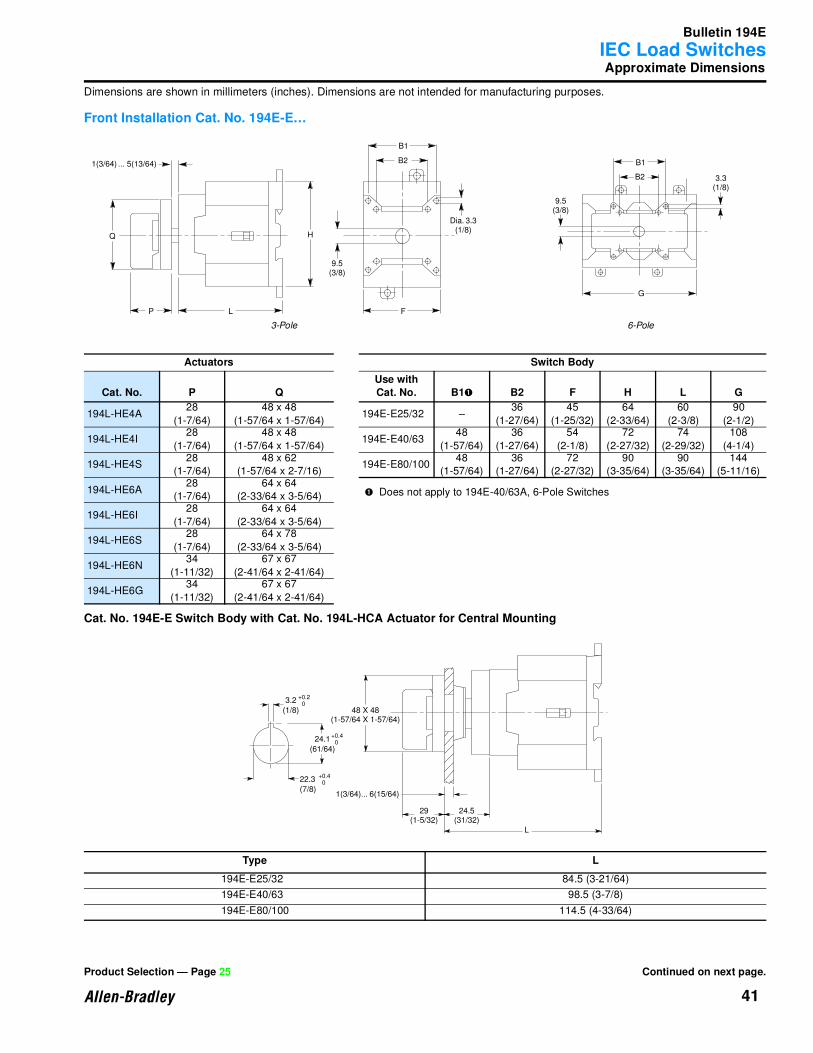
Front Installation Cat. No. 194E-E…
Cat. No. 194E-E Switch Body with Cat. No. 194L-HCA Actuator for Central Mounting
Actuators Switch Body
Cat. No. P QUse with Cat. No. B1➊ B2 F H L G
194L-HE4A28
(1-7/64)
48 x 48
(1-57/64 x 1-57/64)194E-E25/32 –
36
(1-27/64)
45
(1-25/32)
64
(2-33/64)
60
(2-3/8)
90
(2-1/2)
194L-HE4I28
(1-7/64)
48 x 48
(1-57/64 x 1-57/64)194E-E40/63
48
(1-57/64)
36
(1-27/64)
54
(2-1/8)
72
(2-27/32)
74
(2-29/32)
108
(4-1/4)
194L-HE4S28
(1-7/64)
48 x 62
(1-57/64 x 2-7/16)194E-E80/100
48
(1-57/64)
36
(1-27/64)
72
(2-27/32)
90
(3-35/64)
90
(3-35/64)
144
(5-11/16)
194L-HE6A28
(1-7/64)
64 x 64
(2-33/64 x 3-5/64) ➊ Does not apply to 194E-40/63A, 6-Pole Switches
194L-HE6I28
(1-7/64)
64 x 64
(2-33/64 x 3-5/64)
194L-HE6S28
(1-7/64)
64 x 78
(2-33/64 x 3-5/64)
194L-HE6N34
(1-11/32)
67 x 67
(2-41/64 x 2-41/64)
194L-HE6G34
(1-11/32)
67 x 67
(2-41/64 x 2-41/64)
Type L
194E-E25/32 84.5 (3-21/64)
194E-E40/63 98.5 (3-7/8)
194E-E80/100 114.5 (4-33/64)
G
B1
B2
9.5(3/8)
3.3(1/8)
P L F
HQ
B1
B2
9.5(3/8)
Dia. 3.3(1/8)
1(3/64) ... 5(13/64)
3-Pole 6-Pole
L
24.5(31/32)
29(1-5/32)
1(3/64)... 6(15/64)
48 X 48(1-57/64 X 1-57/64)
+0.4 022.3
(7/8)
+0.4 024.1
(61/64)
+0.2 0
3.2
(1/8)
Product Selection — Page 25 Continued on next page.
Bulletin 194E
IEC Load Switches
42
Approximate Dimensions, Continued
Dimensions are shown in millimeters (inches). Dimensions are not intended for manufacturing purposes.
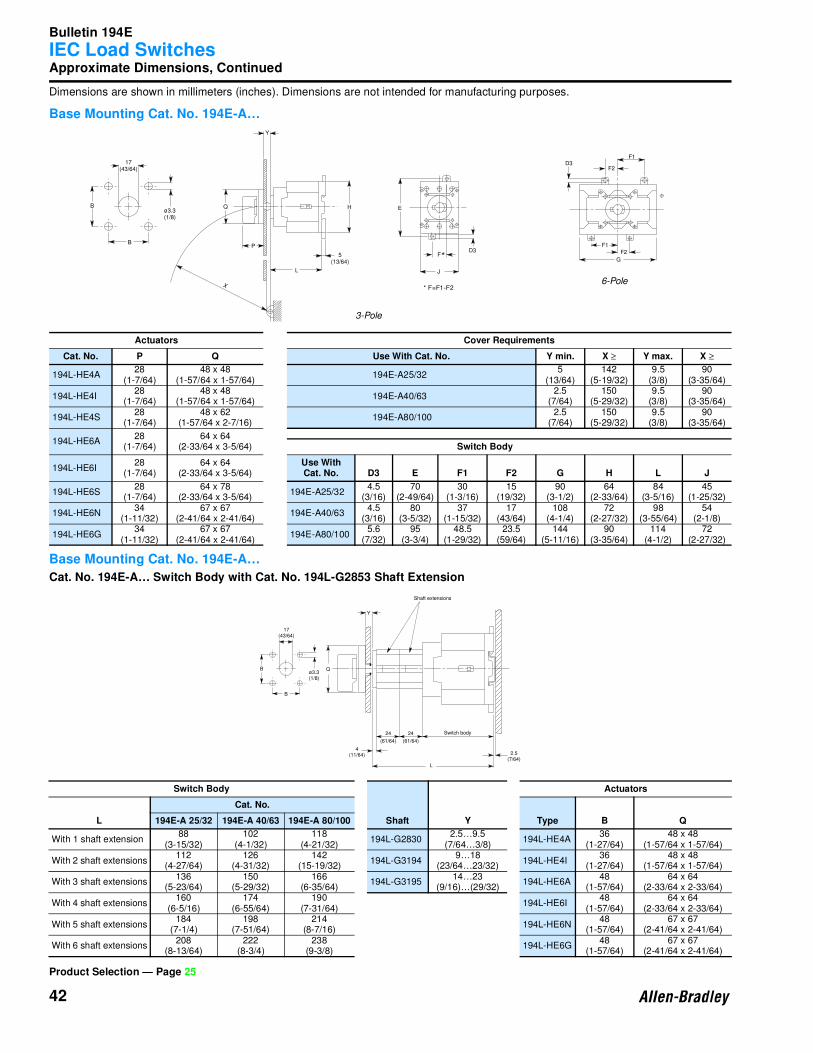
Base Mounting Cat. No. 194E-A…
Base Mounting Cat. No. 194E-A…
Cat. No. 194E-A… Switch Body with Cat. No. 194L-G2853 Shaft Extension
Actuators Cover Requirements
Cat. No. P Q Use With Cat. No. Y min. X ≥ Y max. X ≥
194L-HE4A28
(1-7/64)48 x 48
(1-57/64 x 1-57/64)194E-A25/32
5(13/64)
142(5-19/32)
9.5(3/8)
90(3-35/64)
194L-HE4I28
(1-7/64)48 x 48
(1-57/64 x 1-57/64)194E-A40/63
2.5(7/64)
150(5-29/32)
9.5(3/8)
90(3-35/64)
194L-HE4S28
(1-7/64)48 x 62
(1-57/64 x 2-7/16)194E-A80/100
2.5(7/64)
150(5-29/32)
9.5(3/8)
90(3-35/64)
194L-HE6A28
(1-7/64)64 x 64
(2-33/64 x 3-5/64) Switch Body
194L-HE6I28
(1-7/64)64 x 64
(2-33/64 x 3-5/64)Use With Cat. No. D3 E F1 F2 G H L J
194L-HE6S28
(1-7/64)64 x 78
(2-33/64 x 3-5/64)194E-A25/32
4.5(3/16)
70(2-49/64)
30(1-3/16)
15(19/32)
90(3-1/2)
64(2-33/64)
84(3-5/16)
45(1-25/32)
194L-HE6N34
(1-11/32)67 x 67
(2-41/64 x 2-41/64)194E-A40/63
4.5(3/16)
80(3-5/32)
37(1-15/32)
17(43/64)
108(4-1/4)
72(2-27/32)
98(3-55/64)
54(2-1/8)
194L-HE6G34
(1-11/32)67 x 67
(2-41/64 x 2-41/64)194E-A80/100
5.6(7/32)
95(3-3/4)
48.5(1-29/32)
23.5(59/64)
144(5-11/16)
90(3-35/64)
114(4-1/2)
72(2-27/32)
Switch Body
Shaft Y
Actuators
L
Cat. No.
Type B Q194E-A 25/32 194E-A 40/63 194E-A 80/100
With 1 shaft extension88
(3-15/32)102
(4-1/32)118
(4-21/32)194L-G2830
2.5…9.5(7/64…3/8)
194L-HE4A36
(1-27/64)48 x 48
(1-57/64 x 1-57/64)
With 2 shaft extensions112
(4-27/64)126
(4-31/32)142
(15-19/32)194L-G3194
9…18(23/64…23/32)
194L-HE4I36
(1-27/64)48 x 48
(1-57/64 x 1-57/64)
With 3 shaft extensions136
(5-23/64)150
(5-29/32)166
(6-35/64)194L-G3195
14…23(9/16)…(29/32)
194L-HE6A48
(1-57/64)64 x 64
(2-33/64 x 2-33/64)
With 4 shaft extensions160
(6-5/16)174
(6-55/64)190
(7-31/64)194L-HE6I
48(1-57/64)
64 x 64(2-33/64 x 2-33/64)
With 5 shaft extensions184
(7-1/4)198
(7-51/64)214
(8-7/16)194L-HE6N
48(1-57/64)
67 x 67(2-41/64 x 2-41/64)
With 6 shaft extensions208
(8-13/64)222
(8-3/4)238
(9-3/8)194L-HE6G
48(1-57/64)
67 x 67(2-41/64 x 2-41/64)
Product Selection — Page 25
G
F1
F2
F1F2
D3
L
X
H E
F
J
5(13/64)
Q
P
Y
D3
17(43/64)
B
B
ø3.3(1/8)
3-Pole
6-Pole
*
* F=F1-F2
L
2.5(7/64)
24
(61/64)
4(11/64)
24
(61/64)
Switch body
Q
Y
Shaft extensions
17(43/64)
B
B
ø3.3(1/8)

Bulletin 194E
IEC Load Switches
43
Approximate Dimensions, Continued
Dimensions are shown in millimeters (inches). Dimensions are not intended for manufacturing purposes.
Front Installation Cat. No. 194E-E…
Cat. No. 194E-E Switch Body with Metal Shaft Extension
➊ +2.5 (7/64) [DIN 46 277] 35 (1-3/8) Rails.
Base and Front Installation
Cat. No. 194E… with Auxiliary Contact Block Installed
Cat. No. 194E… with 4-Pole, Ground and Neutral Terminals
Cat. No. A Cat. No. L ➊
194L-G3393110…235
(4-11/32…9-1/4)194E-A25/32
60
(2-3/8)
194L-G3394230…350
(9-1/16…13-25/32)194E-A40/63
74
(2-59/64)
194E-A80/10090
(3-35/64)
Contacts M
1 N.O. + 1 N.C.9
(23/64)
2 N.O. + 2 N.C.18
(23/32)
Cat. No. M
194E-25/3214
(9/16)
194E-40/6317.5
(11/16)
194E-80/10022
(7/8)
Product Selection — Page 25 Continued on next page.
LA
2.5(7/64)... 9.5 (3/8)
M M
M M
Bulletin 194E
IEC Load Switches
44
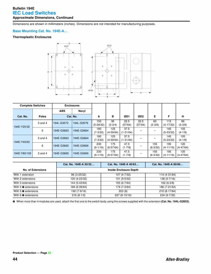
Approximate Dimensions, Continued
Dimensions are shown in millimeters (inches). Dimensions are not intended for manufacturing purposes.
Base Mounting Cat. No. 194E-A…
Thermoplastic Enclosures
➊ When more than 4 modules are used, attach the first one to the switch body using the screws supplied with the extension (Cat. No. 194L-G2853).
Complete Switches Enclosures
A B ØD1 ØD2 E F HCat. No. Poles
ABS Noryl
Cat. No.
194E-Y25/32
3 and 4 194L-G3572 194L-G3576150
(5-29/32)
95
(3-3/4)
22.5
(57/64)
22.5
(57/64)
60
(2-3/8)
115
(4-17/32)
86
(3-3/8)
6 194E-G3663 194E-G3664180
(7-3/32)
125
(4-59/64)
37.5
(1-31/64)– –
145
(5-23/32)
105
(4-1/8)
194E-Y40/63
3 and 4 194E-G3663 194E-G3664180
(7-3/32)
125
(4-59/64)
37.5
(1-31/64)– –
145
(5-23/32)
105
(4-1/8)
6 194E-G3665 194E-G3666230
(9-1/16)
175
(6-57/64)
47.5
(1-7/8)–
155
(6-3/32)
195
(4-11/16)
120
(4-47/64)
194E-Y80/100 3 and 4 194E-G3665 194E-G3666230
(9-1/16)
175
(6-57/64)
47.5
(1-7/8)–
155
(6-3/32)
195
(4-11/16)
120
(4-47/64)
No. of Extensions
Cat. No. 194E-A 20/32… Cat. No. 194E-A 40/63… Cat. No. 194E-A 80/00…
Inside Enclosure Depth
With 1 extension 96 (3-25/32) 107 (4-7/32) 114 (4-31/64)
With 2 extensions 120 (4-23/32) 131 (5-5/32) 138 (5-7/16)
With 3 extensions 144 (5-43/64) 155 (6-7/64) 162 (6-3/8)
With 4 ➊ extensions 168 (6-39/64) 179 (7-3/64) 186 (7-21/64)
With 5 ➊ extensions 192 (7-9/16) 203 (8) 210 (8-17/64)
With 6 ➊ extensions 216 (8-1/2) 227 (8-15/16) 234 (9-7/32)
Product Selection — Page 25
H
EØ D1Ø D1
Ø D2
B
B
F FA
E

Bulletin 194E
IEC Load Switches
45
Approximate Dimensions, Continued
Dimensions are shown in millimeters (inches). Dimensions are not intended for manufacturing purposes.
Enclosed Switches
Product Selection — Page 25
7-7/8(200.2)
2(50.8)
4-15/16(125.5)
1-15/64(31.2)
(4)- 5/16 (7.9)DIA.MTG. HOLES
7-1/2(190.5)
6-3/4(171.5)
3/8(9.7)
1-15/64(31.2)
(4)- 5/16 (7.9)DIA.MTG. HOLES
9-1/2(241.3)
8-3/4(222.3)
7-23/64(186.9)
4.00(101.6
6-15/16(176.3)
3/8(9.7)
10-15/16(277.9)
10(254.0)
7-3/8(188.0)
6-1/2(164.1)
1/2(11.9)
1/2(11.9)
(4)-5/16 (7.1)DIA.MTG. HOLES
8-11/16 (220.5)
7-1/2(190.5)
4-29/32(125.0)
6-7/8(175.0)
6-3/16(157.0)
(4)-3/16 (4.6) DIA.MTG. HOLES
11/32(8.9)
4-3/16(106.9)
Dim Ref. A1Cat. Nos. 194E-CA20…63, 194E-FA20…63, 194E-AA20…63
Dim Ref. B1Cat. Nos. 194E-CA80…00, 194E-FA80…00, 194E-AA80…00
Dim Ref. C1Cat. No. 194E-KA20…63
Dim Ref. B1Cat. No. 194E-KA80…00
Bulletin 194E
IEC Load Switches
46
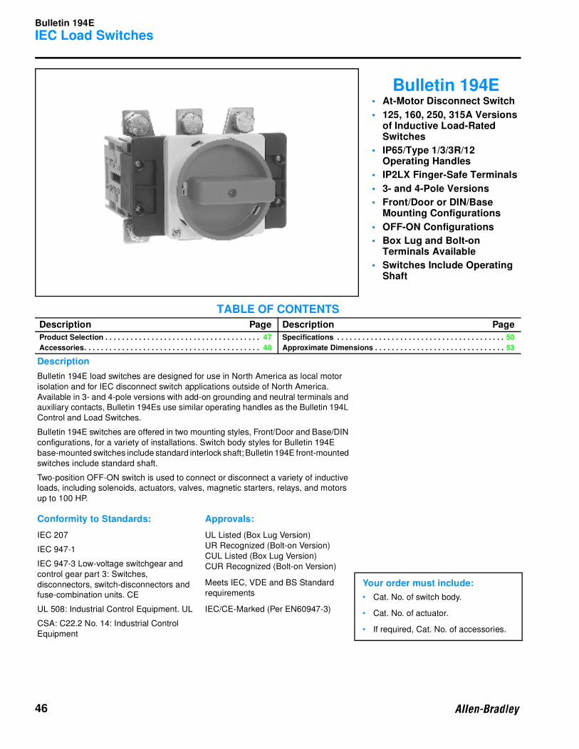
Bulletin 194E• At-Motor Disconnect Switch
• 125, 160, 250, 315A Versions of Inductive Load-Rated Switches
• IP65/Type 1/3/3R/12 Operating Handles
• IP2LX Finger-Safe Terminals
• 3- and 4-Pole Versions
• Front/Door or DIN/Base Mounting Configurations
• OFF-ON Configurations
• Box Lug and Bolt-on Terminals Available
• Switches Include Operating Shaft
TABLE OF CONTENTS
Description Page Description Page
Product Selection . . . . . . . . . . . . . . . . . . . . . . . . . . . . . . . . . . . . . 47
Accessories. . . . . . . . . . . . . . . . . . . . . . . . . . . . . . . . . . . . . . . . . . 48
Specifications . . . . . . . . . . . . . . . . . . . . . . . . . . . . . . . . . . . . . . . . 50
Approximate Dimensions . . . . . . . . . . . . . . . . . . . . . . . . . . . . . . . 53
Description
Bulletin 194E load switches are designed for use in North America as local motor
isolation and for IEC disconnect switch applications outside of North America.
Available in 3- and 4-pole versions with add-on grounding and neutral terminals and
auxiliary contacts, Bulletin 194Es use similar operating handles as the Bulletin 194L
Control and Load Switches.
Bulletin 194E switches are offered in two mounting styles, Front/Door and Base/DIN
configurations, for a variety of installations. Switch body styles for Bulletin 194E
base-mounted switches include standard interlock shaft; Bulletin 194E front-mounted
switches include standard shaft.
Two-position OFF-ON switch is used to connect or disconnect a variety of inductive
loads, including solenoids, actuators, valves, magnetic starters, relays, and motors
up to 100 HP.
Conformity to Standards: Approvals:
IEC 207 UL Listed (Box Lug Version)
UR Recognized (Bolt-on Version)
CUL Listed (Box Lug Version)
CUR Recognized (Bolt-on Version)
IEC 947-1
IEC 947-3 Low-voltage switchgear and
control gear part 3: Switches,
disconnectors, switch-disconnectors and
fuse-combination units. CE
Meets IEC, VDE and BS Standard
requirementsYour order must include:
• Cat. No. of switch body.
• Cat. No. of actuator.
• If required, Cat. No. of accessories.
UL 508: Industrial Control Equipment. UL IEC/CE-Marked (Per EN60947-3)
CSA: C22.2 No. 14: Industrial Control
Equipment
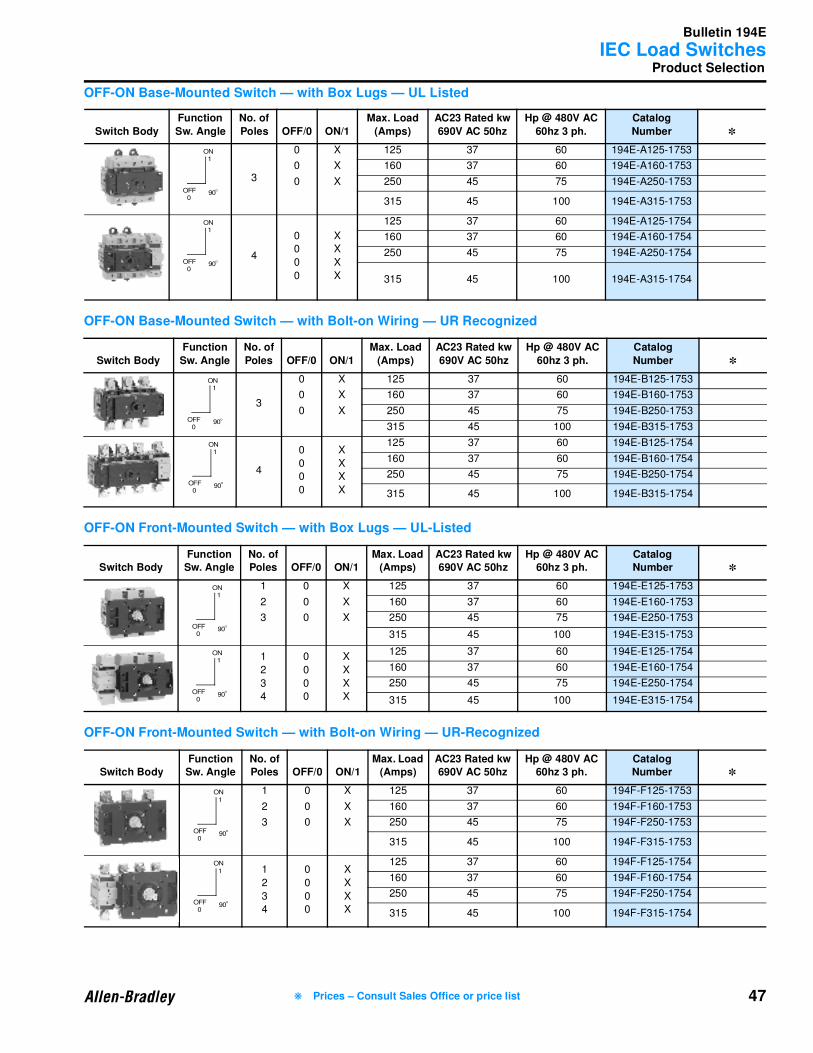
Bulletin 194E
IEC Load Switches
47
Product Selection
OFF-ON Base-Mounted Switch — with Box Lugs — UL Listed
OFF-ON Base-Mounted Switch — with Bolt-on Wiring — UR Recognized
OFF-ON Front-Mounted Switch — with Box Lugs — UL-Listed
OFF-ON Front-Mounted Switch — with Bolt-on Wiring — UR-Recognized
Switch Body
Function
Sw. Angle
No. of
Poles OFF/0 ON/1
Max. Load
(Amps)
AC23 Rated kw
690V AC 50hz
Hp @ 480V AC
60hz 3 ph.
Catalog
Number ✽
3
0 X 125 37 60 194E-A125-1753
0 X 160 37 60 194E-A160-1753
0 X 250 45 75 194E-A250-1753
315 45 100 194E-A315-1753
4
0
0
0
0
X
X
X
X
125 37 60 194E-A125-1754
160 37 60 194E-A160-1754
250 45 75 194E-A250-1754
315 45 100 194E-A315-1754
Switch Body
Function
Sw. Angle
No. of
Poles OFF/0 ON/1
Max. Load
(Amps)
AC23 Rated kw
690V AC 50hz
Hp @ 480V AC
60hz 3 ph.
Catalog
Number ✽
3
0 X 125 37 60 194E-B125-1753
0 X 160 37 60 194E-B160-1753
0 X 250 45 75 194E-B250-1753
315 45 100 194E-B315-1753
4
0
0
0
0
X
X
X
X
125 37 60 194E-B125-1754
160 37 60 194E-B160-1754
250 45 75 194E-B250-1754
315 45 100 194E-B315-1754
Switch BodyFunction Sw. Angle
No. of Poles OFF/0 ON/1
Max. Load (Amps)
AC23 Rated kw690V AC 50hz
Hp @ 480V AC60hz 3 ph.
CatalogNumber ✽
1 0 X 125 37 60 194E-E125-1753
2 0 X 160 37 60 194E-E160-1753
3 0 X 250 45 75 194E-E250-1753
315 45 100 194E-E315-1753
1
2
3
4
0
0
0
0
X
X
X
X
125 37 60 194E-E125-1754
160 37 60 194E-E160-1754
250 45 75 194E-E250-1754
315 45 100 194E-E315-1754
Switch BodyFunction Sw. Angle
No. of Poles OFF/0 ON/1
Max. Load (Amps)
AC23 Rated kw690V AC 50hz
Hp @ 480V AC60hz 3 ph.
CatalogNumber ✽
1 0 X 125 37 60 194F-F125-1753
2 0 X 160 37 60 194F-F160-1753
3 0 X 250 45 75 194F-F250-1753
315 45 100 194F-F315-1753
1
2
3
4
0
0
0
0
X
X
X
X
125 37 60 194F-F125-1754
160 37 60 194F-F160-1754
250 45 75 194F-F250-1754
315 45 100 194F-F315-1754
90
ON
OFF O
1
0
90
ON
OFF O
1
0
90
ON
OFF O
1
0
90
ON
OFF O
1
0
90
ON
OFF O
1
0
90
ON
OFF O
1
0
90
ON
OFF O
1
0
90
ON
OFF O
1
0
❋ Prices – Consult Sales Office or price list
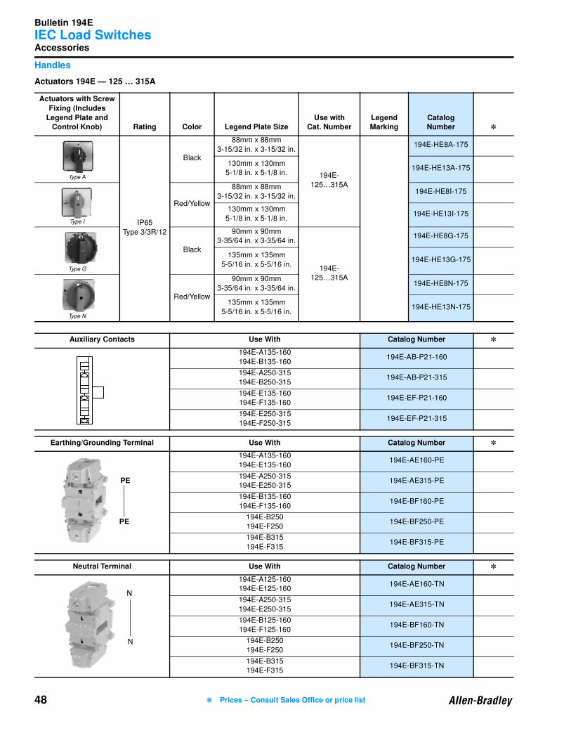
Bulletin 194E
IEC Load Switches
48
Accessories
Handles
Actuators 194E — 125 … 315A
Actuators with Screw
Fixing (Includes
Legend Plate and Control Knob) Rating Color Legend Plate Size
Use with Cat. Number
Legend Marking
CatalogNumber ✽
Type A
IP65
Type 3/3R/12
Black
88mm x 88mm
3-15/32 in. x 3-15/32 in.
194E-
125…315A
194E-HE8A-175
130mm x 130mm
5-1/8 in. x 5-1/8 in.194E-HE13A-175
Type I
Red/Yellow
88mm x 88mm
3-15/32 in. x 3-15/32 in.194E-HE8I-175
130mm x 130mm
5-1/8 in. x 5-1/8 in.194E-HE13I-175
Type G
Black
90mm x 90mm
3-35/64 in. x 3-35/64 in.
194E-
125…315A
194E-HE8G-175
135mm x 135mm
5-5/16 in. x 5-5/16 in.194E-HE13G-175
Type N
Red/Yellow
90mm x 90mm
3-35/64 in. x 3-35/64 in.194E-HE8N-175
135mm x 135mm
5-5/16 in. x 5-5/16 in.194E-HE13N-175
Auxiliary Contacts Use With Catalog Number ✽
194E-A135-160
194E-B135-160194E-AB-P21-160
194E-A250-315
194E-B250-315194E-AB-P21-315
194E-E135-160
194E-F135-160194E-EF-P21-160
194E-E250-315
194E-F250-315194E-EF-P21-315
Earthing/Grounding Terminal Use With Catalog Number ✽
194E-A135-160
194E-E135-160194E-AE160-PE
194E-A250-315
194E-E250-315194E-AE315-PE
194E-B135-160
194E-F135-160194E-BF160-PE
194E-B250
194E-F250194E-BF250-PE
194E-B315
194E-F315194E-BF315-PE
Neutral Terminal Use With Catalog Number ✽
194E-A125-160
194E-E125-160194E-AE160-TN
194E-A250-315
194E-E250-315194E-AE315-TN
194E-B125-160
194E-F125-160194E-BF160-TN
194E-B250
194E-F250194E-BF250-TN
194E-B315
194E-F315194E-BF315-TN
PE
PE
❋ Prices – Consult Sales Office or price list
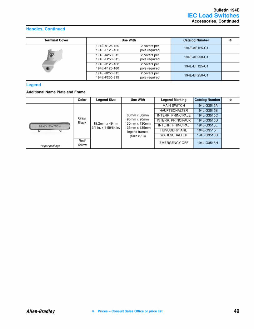
Bulletin 194E
IEC Load Switches
49
Accessories, Continued
Handles, Continued
Legend
Additional Name Plate and Frame
Terminal Cover Use With Catalog Number ✽
194E-A125-160
194E-E125-160
2 covers per
pole required194E-AE125-C1
194E-A250-315
194E-E250-315
2 covers per
pole required194E-AE250-C1
194E-B125-160
194E-F125-160
2 covers per
pole required194E-BF125-C1
194E-B250-315
194E-F250-315
2 covers per
pole required194E-BF250-C1
Color Legend Size Use With Legend Marking Catalog Number ✽
10 per package
Gray/
Black 19.2mm x 49mm
3/4 in. x 1-59/64 in.
88mm x 88mm
90mm x 90mm
130mm x 130mm
135mm x 135mm
legend frames
(Size 8,13)
MAIN SWITCH 194L-G3515A
HAUPTSCHALTER 194L-G3515B
INTERR. PRINCIPALE 194L-G3515C
INTERR. PRINCIPAUX 194L-G3515D
INTERR. PRINCIPAL 194L-G3515E
HUVUDBRYTARE 194L-G3515F
WAHLSCHALTER 194L-G3515G
Red/
YellowEMERGENCY OFF 194L-G3515H
❋ Prices – Consult Sales Office or price list
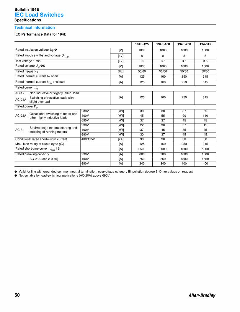
Bulletin 194E
IEC Load Switches
50
Specifications
Technical Information
IEC Performance Data for 194E
➊ Valid for line with grounded common neutral termination, overvoltage category III, pollution degree 3. Other values on request.
➋ Not suitable for load-switching applications (AC-20A) above 690V.
194E-125 194E-160 194E-250 194-315
Rated insulation voltage Ui: ➊ [V] 1000 1000 1000 1000
Rated impulse withstand voltage Uimp [kV] 8 8 8 8
Test voltage 1 min [kV] 3.5 3.5 3.5 3.5
Rated voltage Ue ➊➋ [V] 1000 1000 1000 1000
Rated frequency [Hz] 50/60 50/60 50/60 50/60
Rated thermal current Ith open [A] 125 160 250 315
Rated thermal current Ithe enclosed [A] 125 160 250 315
Rated current Ie
AC-1 / Non-inductive or slightly induc. load
[A] 125 160 250 315AC-21A
Switching of resistive loads with
slight overload
Rated power Pe
AC-23AOccasional switching of motor and
other highly inductive loads
230V [kW] 30 30 37 55
400V [kW] 45 55 90 110
690V [kW] 37 37 45 45
AC-3Squirrel-cage motors: starting and
stopping of running motors
230V [kW] 22 30 37 45
400V [kW] 37 45 55 75
690V [kW] 30 37 45 45
Conditional rated short-circuit current 400/415V [kA] 30 30 30 30
Max. fuse rating of circuit (type gG) [A] 125 160 250 315
Rated short-time current Icw 1S [A] 2500 3000 4600 5800
Rated breaking capacity 230V [A] 800 900 1600 1800
AC-23A (cos ϕ 0.45) 400V [A] 750 850 1380 1650
690V [A] 340 340 400 400

Bulletin 194E
IEC Load Switches
51
Specifications, Continued
Technical Information, Continued
IEC Performance Data for 194E, Continued
UL CSA Performance Data for 194E
DC Switching Capacity
194E-125 194E-160 194E-250 194E-315
Rated current Ie
Rated voltage [V] No. Poles in series
DC-21A 60 3 [A] 125 160 250 315
For resistive loads T≤1 ms 110 3 [A] 110 140 220 280
220 3 [A] 45 55 85 110
Rated voltage [V] No. Poles in series
110 4 [A] 125 160 250 315
220 4 [A] 80 100 150 200
440 4 [A] 16 20 32 40
Rated power Pe
Rated voltage [V] No. Poles in series
DC-22A, DC-3 24 4 [kW] 3 3.8 6 7.5
For Inductive loads T≤2.5 ms 48 4 [kW] 6 7.5 12 15
60 4 [kW] 7.5 9.5 15 19
110 4 [kW] 10 12.5 20 25
220 4 [kW] 4.5 5.5 8 10
Rated Power Pe
Rated voltage [V] No. Poles in series
DC-23A, DC-5 24 4 [kW] 3 3.8 6 7.5
For Inductive loads T≤15 ms 48 4 [kW] 6 7.5 12 15
60 4 [kW] 7.5 9.5 15 19
110 4 [kW] 8.8 11 17.5 22
220 4 [kW] 2.5 3.5 5.5 7
194E-125 194E-160 194E-250 194E-315
Rated Insulation Voltage [V] 600 600 600 600
Rated voltage [V] 600 600 600 600
Continuous current [A] 150 200 250 300
Ampere rating for general use [A] 150 200 250 300
Heavy Pilot Duty [AC]
Standard Duty [DC]
Motor rating 60Hz
1-phase (2 poles)
120V, 1 P [FLA] 80 100 135 180
[HP] 7.5 10 15 20
240V, 1 P [FLA] 88 110 136 155
[HP] 20 25 30 35
480V, 1 P [FLA] 78 88 99 108
[HP] 35 40 45 50
600V, 1 P [FLA] 62 70 86 104
[HP] 35 40 50 60
3-Phase
120V, 3 P [FLA] 84 108 160 208
[HP] 15 20 30 40
240V, 3 P [FLA] 8 104 154 192
[HP] 30 40 60 75
480V, 3 P [FLA] 77 77 96 124
[HP] 60 60 75 100
600V, 3 P [FLA] 62 62 77 99
[HP] 60 60 75 100
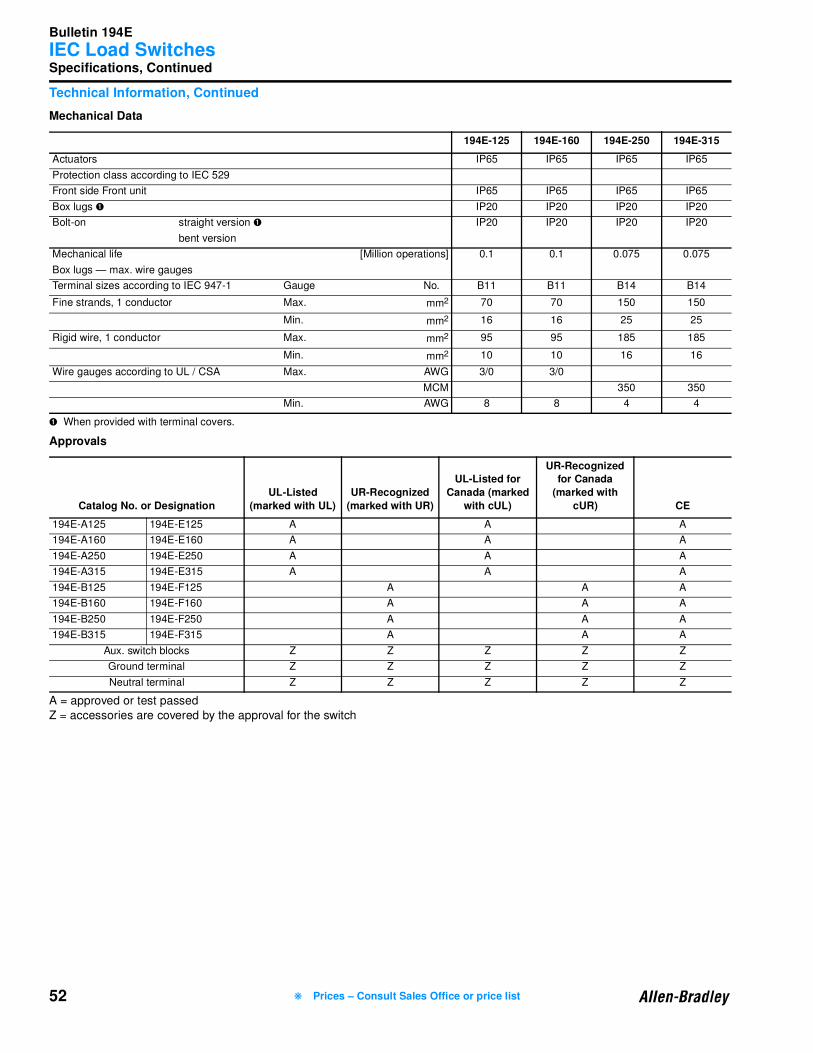
Bulletin 194E
IEC Load Switches
52
Specifications, Continued
Technical Information, Continued
Mechanical Data
➊ When provided with terminal covers.
Approvals
A = approved or test passed
Z = accessories are covered by the approval for the switch
194E-125 194E-160 194E-250 194E-315
Actuators IP65 IP65 IP65 IP65
Protection class according to IEC 529
Front side Front unit IP65 IP65 IP65 IP65
Box lugs ➊ IP20 IP20 IP20 IP20
Bolt-on straight version ➊ IP20 IP20 IP20 IP20
bent version
Mechanical life [Million operations] 0.1 0.1 0.075 0.075
Box lugs — max. wire gauges
Terminal sizes according to IEC 947-1 Gauge No. B11 B11 B14 B14
Fine strands, 1 conductor Max. mm2 70 70 150 150
Min. mm2 16 16 25 25
Rigid wire, 1 conductor Max. mm2 95 95 185 185
Min. mm2 10 10 16 16
Wire gauges according to UL / CSA Max. AWG 3/0 3/0
MCM 350 350
Min. AWG 8 8 4 4
Catalog No. or Designation
UL-Listed
(marked with UL)
UR-Recognized
(marked with UR)
UL-Listed for
Canada (marked
with cUL)
UR-Recognized for Canada
(marked with
cUR) CE
194E-A125 194E-E125 A A A
194E-A160 194E-E160 A A A
194E-A250 194E-E250 A A A
194E-A315 194E-E315 A A A
194E-B125 194E-F125 A A A
194E-B160 194E-F160 A A A
194E-B250 194E-F250 A A A
194E-B315 194E-F315 A A A
Aux. switch blocks Z Z Z Z Z
Ground terminal Z Z Z Z Z
Neutral terminal Z Z Z Z Z
❋ Prices – Consult Sales Office or price list
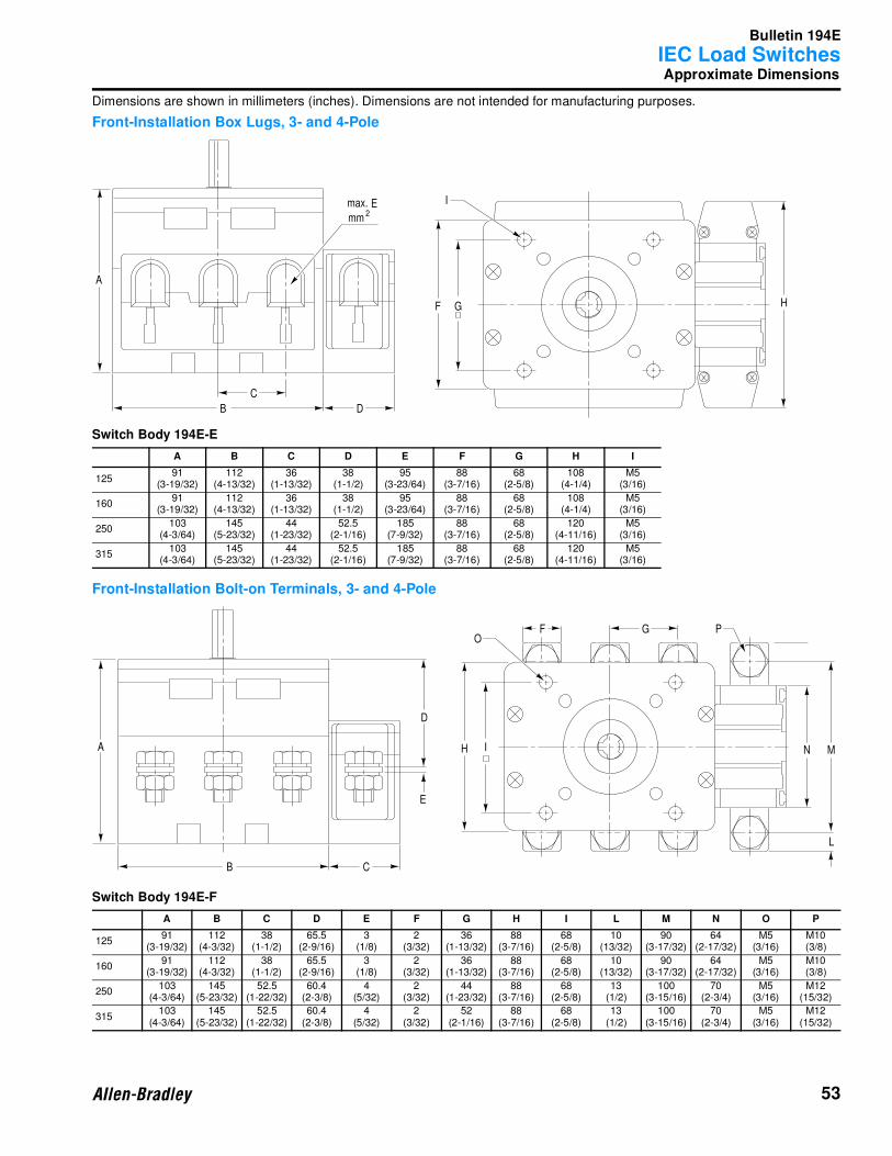
Bulletin 194E
IEC Load Switches
53
Approximate Dimensions
Dimensions are shown in millimeters (inches). Dimensions are not intended for manufacturing purposes.
Front-Installation Box Lugs, 3- and 4-Pole
Switch Body 194E-E
Front-Installation Bolt-on Terminals, 3- and 4-Pole
Switch Body 194E-F
A B C D E F G H I
12591
(3-19/32)112
(4-13/32)36
(1-13/32)38
(1-1/2)95
(3-23/64)88
(3-7/16)68
(2-5/8)108
(4-1/4)M5
(3/16)
16091
(3-19/32)112
(4-13/32)36
(1-13/32)38
(1-1/2)95
(3-23/64)88
(3-7/16)68
(2-5/8)108
(4-1/4)M5
(3/16)
250103
(4-3/64)145
(5-23/32)44
(1-23/32)52.5
(2-1/16)185
(7-9/32)88
(3-7/16)68
(2-5/8)120
(4-11/16)M5
(3/16)
315103
(4-3/64)145
(5-23/32)44
(1-23/32)52.5
(2-1/16)185
(7-9/32)88
(3-7/16)68
(2-5/8)120
(4-11/16)M5
(3/16)
A B C D E F G H I L M N O P
12591
(3-19/32)112
(4-3/32)38
(1-1/2)65.5
(2-9/16)3
(1/8)2
(3/32)36
(1-13/32)88
(3-7/16)68
(2-5/8)10
(13/32)90
(3-17/32)64
(2-17/32)M5
(3/16)M10(3/8)
16091
(3-19/32)112
(4-3/32)38
(1-1/2)65.5
(2-9/16)3
(1/8)2
(3/32)36
(1-13/32)88
(3-7/16)68
(2-5/8)10
(13/32)90
(3-17/32)64
(2-17/32)M5
(3/16)M10(3/8)
250103
(4-3/64)145
(5-23/32)52.5
(1-22/32)60.4
(2-3/8)4
(5/32)2
(3/32)44
(1-23/32)88
(3-7/16)68
(2-5/8)13
(1/2)100
(3-15/16)70
(2-3/4)M5
(3/16)M12
(15/32)
315103
(4-3/64)145
(5-23/32)52.5
(1-22/32)60.4
(2-3/8)4
(5/32)2
(3/32)52
(2-1/16)88
(3-7/16)68
(2-5/8)13
(1/2)100
(3-15/16)70
(2-3/4)M5
(3/16)M12
(15/32)
GF H
C
B
A
D
E2
max.
mm
I
M
L
N
PGFO
H
CB
A
D
E
I
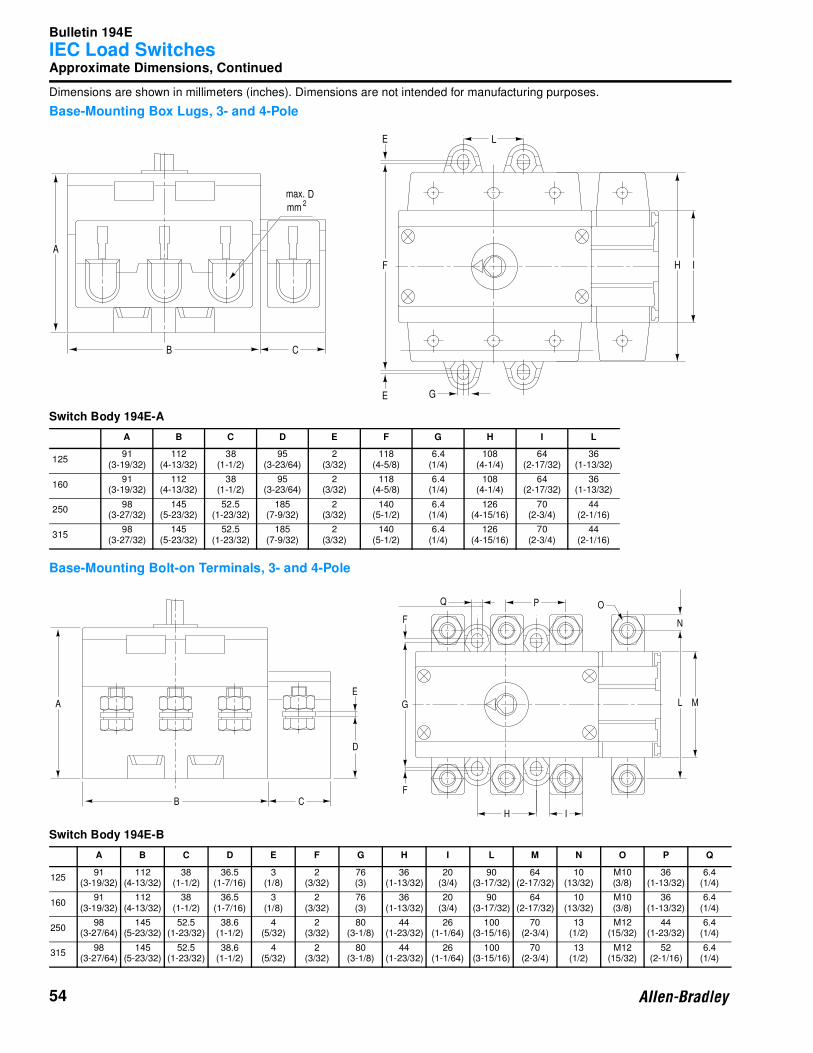
Bulletin 194E
IEC Load Switches
54
Approximate Dimensions, Continued
Dimensions are shown in millimeters (inches). Dimensions are not intended for manufacturing purposes.
Base-Mounting Box Lugs, 3- and 4-Pole
Switch Body 194E-A
Base-Mounting Bolt-on Terminals, 3- and 4-Pole
Switch Body 194E-B
A B C D E F G H I L
12591
(3-19/32)112
(4-13/32)38
(1-1/2)95
(3-23/64)2
(3/32)118
(4-5/8)6.4
(1/4)108
(4-1/4)64
(2-17/32)36
(1-13/32)
16091
(3-19/32)112
(4-13/32)38
(1-1/2)95
(3-23/64)2
(3/32)118
(4-5/8)6.4
(1/4)108
(4-1/4)64
(2-17/32)36
(1-13/32)
25098
(3-27/32)145
(5-23/32)52.5
(1-23/32)185
(7-9/32)2
(3/32)140
(5-1/2)6.4
(1/4)126
(4-15/16)70
(2-3/4)44
(2-1/16)
31598
(3-27/32)145
(5-23/32)52.5
(1-23/32)185
(7-9/32)2
(3/32)140
(5-1/2)6.4
(1/4)126
(4-15/16)70
(2-3/4)44
(2-1/16)
A B C D E F G H I L M N O P Q
12591
(3-19/32)112
(4-13/32)38
(1-1/2)36.5
(1-7/16)3
(1/8)2
(3/32)76(3)
36(1-13/32)
20(3/4)
90(3-17/32)
64(2-17/32)
10(13/32)
M10(3/8)
36(1-13/32)
6.4(1/4)
16091
(3-19/32)112
(4-13/32)38
(1-1/2)36.5
(1-7/16)3
(1/8)2
(3/32)76(3)
36(1-13/32)
20(3/4)
90(3-17/32)
64(2-17/32)
10(13/32)
M10(3/8)
36(1-13/32)
6.4(1/4)
25098
(3-27/64)145
(5-23/32)52.5
(1-23/32)38.6
(1-1/2)4
(5/32)2
(3/32)80
(3-1/8)44
(1-23/32)26
(1-1/64)100
(3-15/16)70
(2-3/4)13
(1/2)M12
(15/32)44
(1-23/32)6.4
(1/4)
31598
(3-27/64)145
(5-23/32)52.5
(1-23/32)38.6
(1-1/2)4
(5/32)2
(3/32)80
(3-1/8)44
(1-23/32)26
(1-1/64)100
(3-15/16)70
(2-3/4)13
(1/2)M12
(15/32)52
(2-1/16)6.4
(1/4)
D2
max.
mm
A
B C
E
E L
F
G
H I
D
B
A
C
E
F
F
G
H I
L M
N
OPQ
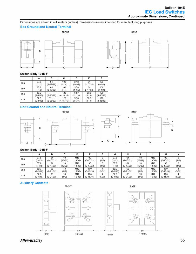
Bulletin 194E
IEC Load Switches
55
Approximate Dimensions, Continued
Dimensions are shown in millimeters (inches). Dimensions are not intended for manufacturing purposes.
Box Ground and Neutral Terminal
Switch Body 194E-F
Bolt Ground and Neutral Terminal
Switch Body 194E-F
Auxiliary Contacts
A B C D E F
12537.8
(1-1/2)64
(2-17/32)108
(4-1/4)37.8
(1-1/2)64
(2-17/32)108
(4-1/4)
16037.8
(1-1/2)64
(2-17/32)108
(4-1/4)37.8
(1-1/2)64
(2-17/32)108
(4-1/4)
25052.3
(2-1/16)71.1
(2-25/32)126
(4-15/16)52.3
(2-1/16)80.6
(3-1/8)126
(4-15/16)
31552.3
(2-1/16)71.1
(2-25/32)126
(4-15/16)52.3
(2-1/16)80.6
(3-1/8)126
(4-15/16)
A B C D E F G H I L M N
12537.8
(1-1/2)64
(2-17/32)10
(13/32)M10
(13/32)90
(3-17/32)3
(1/8)37.8
(1-1/2)64
(2-17/32)10
(13/32)M10
(13/32)90
(3-17/32)3
(1/8)
16037.8
(1-1/2)64
(2-17/32)10
(13/32)M10
(13/32)90
(3-17/32)3
(1/8)37.8
(1-1/2)64
(2-17/32)10
(13/32)M10
(13/32)90
(3-17/32)3
(1/8)
25052.3
(2-1/16)68
(2-21/32)13
(1/2)M12
(15/32)100
(3-15/16)4
(5/32)52.3
(2-1/16)68
(2-21/32)13
(1/2)M12
(15/32)100
(3-15/16)4
(5/32)
31552.3
(2-1/16)68
(2-21/32)13
(1/2)M12
(15/32)100
(3-15/16)4
(5/32)52.3
(2-1/16)68
(2-21/32)13
(1/2)M12
(15/32)100
(3-15/16)4
(5/32)
A
B
FRONT BASE
C D
E
F
A
B
FRONT BASE
C
D
E
F
G
H
I
L
M
N
FRONT BASE
14 1450 50
(9/16) (9/16)(1 31/32) (1 31/32)
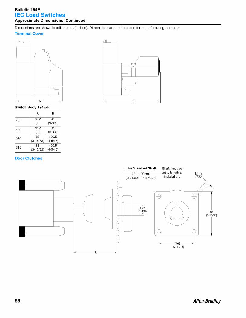
Bulletin 194E
IEC Load Switches
56
Approximate Dimensions, Continued
Dimensions are shown in millimeters (inches). Dimensions are not intended for manufacturing purposes.
Terminal Cover
Switch Body 194E-F
Door Clutches
A B
12576.2
(3)
95
(3-3/4)
16076.2
(3)
95
(3-3/4)
25088
(3-15/32)
109.5
(4-5/16)
31588
(3-15/32)
109.5
(4-5/16)
A B
L
5.4 mm(7/32)
88(3-15/32)
68(2-11/16)
fl 27(1-1/16)
L for Standard Shaft Shaft must be
cut to length at
installation.93 – 199mm
(3-21/32" – 7-27/32")

Bulletin 194E
IEC Load Switches
57
Approximate Dimensions, Continued
Dimensions are shown in millimeters (inches). Dimensions are not intended for manufacturing purposes.
Actuators (Type 194E-HE-8A-8I-8G-8N)
Actuators (Type 194E-HE-13A-13I-13G-13N)
Additional Name Plate
Frame and legend snaps on to actuator bezel. Fits size 8 and 13 actuators.
49(1-15/16)
1-4 mm(1/32-1/8)
1-4 mm(1/32-1/8)
45(1-49/64)
88 x 88(3-15/16 x 3-15/16) 68
(2-11/16)
68(2-11/16)
92 x 92(1-5/8 x 1-5/8)
fl 12(15/32)
fl 5.3(7/32)
68(2-11/16)
1-4 mm(1/32-1/8) 1-4 mm
(1/32-1/8)
55(2-5/32)
130 x 130(5-1/8 x 5-1/8) 135 x 135
(5-5/16 x 5-5/16)68
(2-11/16)
68(2-11/16)
fl 20(15/32)
fl 5.3(7/32)
84(3-5/16)
G3515
18(23/32)
6.7(9/32)
Bulletin 194E
IEC Load Switches
58
Notes
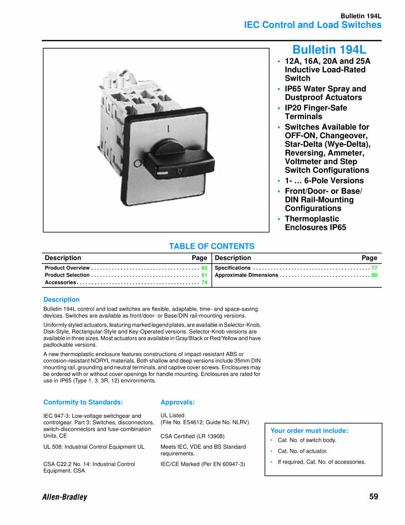
Bulletin 194L
IEC Control and Load Switches
59
Bulletin 194L• 12A, 16A, 20A and 25A
Inductive Load-Rated Switch
• IP65 Water Spray and Dustproof Actuators
• IP20 Finger-Safe Terminals
• Switches Available for OFF-ON, Changeover, Star-Delta (Wye-Delta), Reversing, Ammeter, Voltmeter and Step Switch Configurations
• 1- … 6-Pole Versions
• Front/Door- or Base/DIN Rail-Mounting Configurations
• Thermoplastic Enclosures IP65
TABLE OF CONTENTS
Description Page Description Page
Product Overview . . . . . . . . . . . . . . . . . . . . . . . . . . . . . . . . . . . . . 60
Product Selection . . . . . . . . . . . . . . . . . . . . . . . . . . . . . . . . . . . . . 61
Accessories . . . . . . . . . . . . . . . . . . . . . . . . . . . . . . . . . . . . . . . . . . 74
Specifications . . . . . . . . . . . . . . . . . . . . . . . . . . . . . . . . . . . . . . . . 77
Approximate Dimensions . . . . . . . . . . . . . . . . . . . . . . . . . . . . . . . 80
Description
Bulletin 194L control and load switches are flexible, adaptable, time- and space-saving devices. Switches are available as front/door- or Base/DIN rail-mounting versions.
Uniformly styled actuators, featuring marked legend plates, are available in Selector-Knob, Disk-Style, Rectangular-Style and Key-Operated versions. Selector-Knob versions are available in three sizes. Most actuators are available in Gray/Black or Red/Yellow and have padlockable versions.
A new thermoplastic enclosure features constructions of impact-resistant ABS or corrosion-resistant NORYL materials. Both shallow and deep versions include 35mm DIN mounting rail, grounding and neutral terminals, and captive cover screws. Enclosures may be ordered with or without cover openings for handle mounting. Enclosures are rated for use in IP65 (Type 1, 3, 3R, 12) environments.
Conformity to Standards: Approvals:
IEC 947-3: Low-voltage switchgear and controlgear. Part 3: Switches, disconnectors, switch-disconnectors and fuse-combination Units. CE
UL Listed
(File No. E54612; Guide No. NLRV)
CSA Certified (LR 13908) Your order must include:
• Cat. No. of switch body.
• Cat. No. of actuator.
• If required, Cat. No. of accessories.
UL 508: Industrial Control Equipment UL Meets IEC, VDE and BS Standard requirements.
CSA C22.2 No. 14: Industrial Control Equipment. CSA
IEC/CE Marked (Per EN 60947-3)
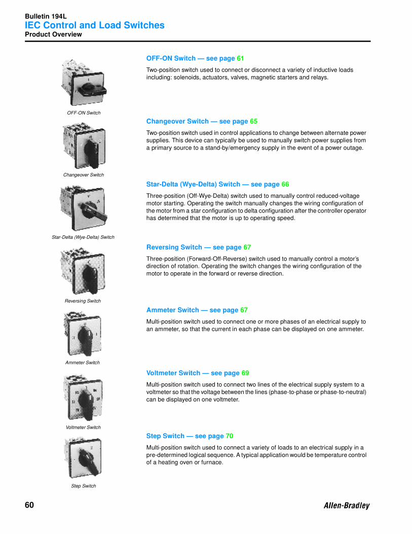
Bulletin 194L
IEC Control and Load Switches
60
Product Overview
OFF-ON Switch — see page 61
Two-position switch used to connect or disconnect a variety of inductive loads
including: solenoids, actuators, valves, magnetic starters and relays.
Changeover Switch — see page 65
Two-position switch used in control applications to change between alternate power
supplies. This device can typically be used to manually switch power supplies from
a primary source to a stand-by/emergency supply in the event of a power outage.
Star-Delta (Wye-Delta) Switch — see page 66
Three-position (Off-Wye-Delta) switch used to manually control reduced-voltage
motor starting. Operating the switch manually changes the wiring configuration of
the motor from a star configuration to delta configuration after the controller operator
has determined that the motor is up to operating speed.
Reversing Switch — see page 67
Three-position (Forward-Off-Reverse) switch used to manually control a motor’s
direction of rotation. Operating the switch changes the wiring configuration of the
motor to operate in the forward or reverse direction.
Ammeter Switch — see page 67
Multi-position switch used to connect one or more phases of an electrical supply to
an ammeter, so that the current in each phase can be displayed on one ammeter.
Voltmeter Switch — see page 69
Multi-position switch used to connect two lines of the electrical supply system to a
voltmeter so that the voltage between the lines (phase-to-phase or phase-to-neutral)
can be displayed on one voltmeter.
Step Switch — see page 70
Multi-position switch used to connect a variety of loads to an electrical supply in a
pre-determined logical sequence. A typical application would be temperature control
of a heating oven or furnace.
OFF-ON Switch
Changeover Switch
Star-Delta (Wye-Delta) Switch
Reversing Switch
Ammeter Switch
Voltmeter Switch
Step Switch

Bulletin 194L
IEC Control and Load Switches
61
Product Selection
OFF-ON Switch (Actuators Listed on pages 62 to 64)
Switch Body
(Includes Shaft)
Function Switch
Angle
Maximum Load
Rating (A)
No. of
Poles
Contact Target
Configuration
X = Contact Closed
O = Contact Open
Mounting
Style Cat. No. ❋
No. of
Circuits
Control Knob
Position
OFF/0 ON/1
12
1 1 O X
Base/DIN 194L-A12-1751
Front/Door 194L-E12-1751
16Base/DIN 194L-A16-1751
Front/Door 194L-E16-1751
20Base/DIN 194L-A20-1751
Front/Door 194L-E20-1751
25Base/DIN 194L-A25-1751
Front/Door 194L-E25-1751
12
21
2
O
O
X
X
Base/DIN 194L-A12-1752
Front/Door 194L-E12-1752
16Base/DIN 194L-A16-1752
Front/Door 194L-E16-1752
20Base/DIN 194L-A20-1752
Front/Door 194L-E20-1752
25Base/DIN 194L-A25-1752
Front/Door 194L-E25-1752
12
3
1
2
3
O
O
O
X
X
X
Base/DIN 194L-A12-1753
Front/Door 194L-E12-1753
16Base/DIN 194L-A16-1753
Front/Door 194L-E16-1753
20Base/DIN 194L-A20-1753
Front/Door 194L-E20-1753
25Base/DIN 194L-A25-1753
Front/Door 194L-E25-1753
12
4
1
2
3
4
O
O
O
O
X
X
X
X
Base/DIN 194L-A12-1754
Front/Door 194L-E12-1754
16Base/DIN 194L-A16-1754
Front/Door 194L-E16-1754
20Base/DIN 194L-A20-1754
Front/Door 194L-E20-1754
25Base/DIN 194L-A25-1754
Front/Door 194L-E25-1754
12
5
1
2
3
4
5
O
O
O
O
O
X
X
X
X
X
Base/DIN 194L-A12-1755
Front/Door 194L-E12-1755
16Base/DIN 194L-A16-1755
Front/Door 194L-E16-1755
20Base/DIN 194L-A20-1755
Front/Door 194L-E20-1755
25Base/DIN 194L-A25-1755
Front/Door 194L-E25-1755
12
6
1
2
3
4
5
6
O
O
O
O
O
O
X
X
X
X
X
X
Base/DIN 194L-A12-1756
Front/Door 194L-E12-1756
16Base/DIN 194L-A16-1756
Front/Door 194L-E16-1756
20Base/DIN 194L-A20-1756
Front/Door 194L-E20-1756
25Base/DIN 194L-A25-1756
Front/Door 194L-E25-1756
Base/DIN Rail-Installed Screw Fixing
Front/Door-Installed Screw Fixing or Central Fixing
With an Actuator
90
ON
OFF O
1
0
❋ Prices – Consult Sales Office or price list
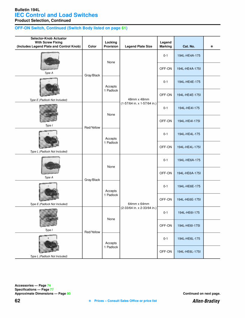
Bulletin 194L
IEC Control and Load Switches
62
Product Selection, Continued
OFF-ON Switch, Continued (Switch Body listed on page 61)
Selector-Knob Actuator With Screw Fixing
(Includes Legend Plate and Control Knob) Color
Locking
Provision Legend Plate Size
Legend
Marking Cat. No. ❋
Gray/Black
None
48mm x 48mm
(1-57/64 in. x 1-57/64 in.)
0-1 194L-HE4A-175
OFF-ON 194L-HE4A-175I
Accepts
1 Padlock
0-1 194L-HE4E-175
OFF-ON 194L-HE4E-175I
Red/Yellow
None
0-1 194L-HE4I-175
OFF-ON 194L-HE4I-175I
Accepts
1 Padlock
0-1 194L-HE4L-175
OFF-ON 194L-HE4L-175I
Gray/Black
None
64mm x 64mm
(2-33/64 in. x 2-33/64 in.)
0-1 194L-HE6A-175
OFF-ON 194L-HE6A-175I
Accepts
1 Padlock
0-1 194L-HE6E-175
OFF-ON 194L-HE6E-175I
Red/Yellow
None
0-1 194L-HE6I-175
OFF-ON 194L-HE6I-175I
Accepts
1 Padlock
0-1 194L-HE6L-175
OFF-ON 194L-HE6L-175I
Type A
Type E (Padlock Not Included)
Type I
Type L (Padlock Not Included)
Type A
Type E (Padlock Not Included)
Type I
Type L (Padlock Not Included)
Accessories — Page 74
Specifications — Page 77
Approximate Dimensions — Page 80 Continued on next page.
❋ Prices – Consult Sales Office or price list
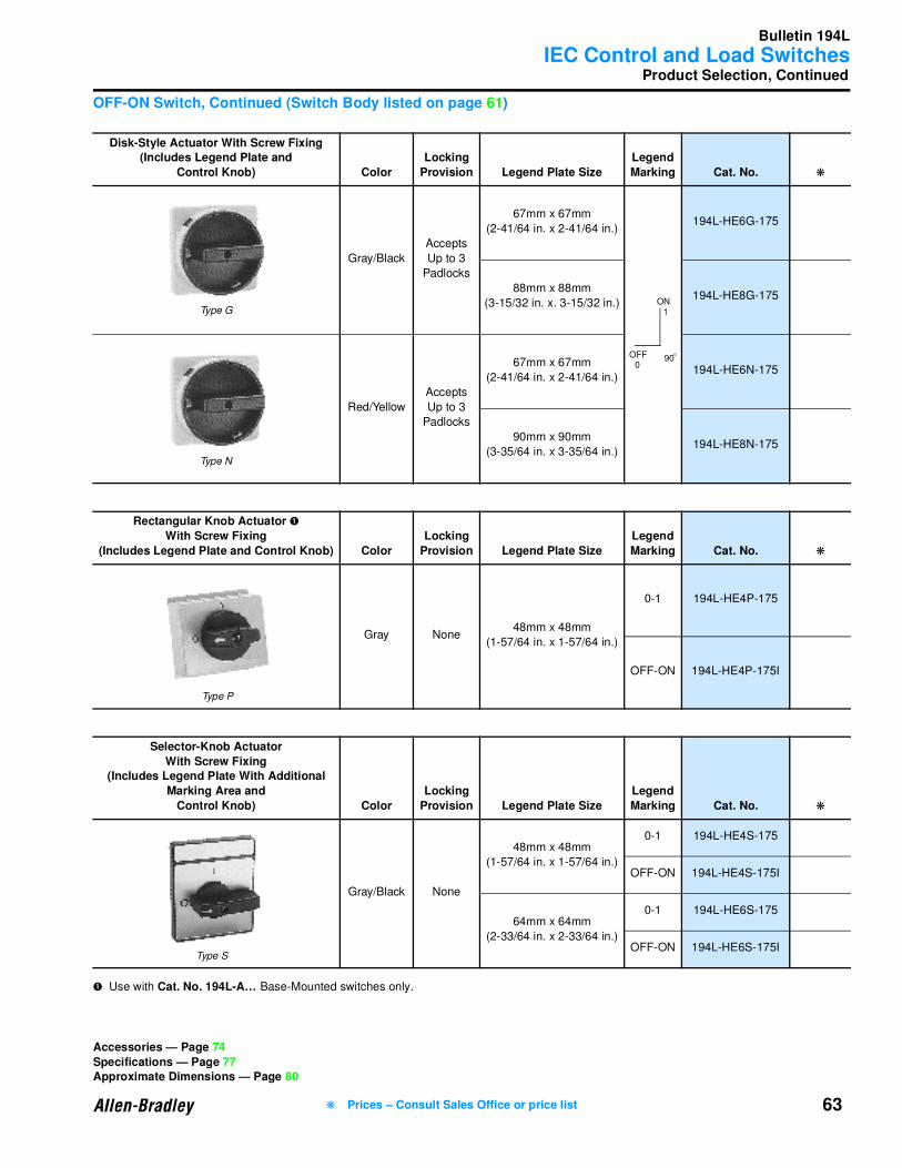
Bulletin 194L
IEC Control and Load Switches
63
Product Selection, Continued
OFF-ON Switch, Continued (Switch Body listed on page 61)
➊ Use with Cat. No. 194L-A… Base-Mounted switches only.
Disk-Style Actuator With Screw Fixing(Includes Legend Plate and
Control Knob) Color
Locking
Provision Legend Plate Size
Legend
Marking Cat. No. ❋
Gray/Black
Accepts
Up to 3
Padlocks
67mm x 67mm
(2-41/64 in. x 2-41/64 in.)194L-HE6G-175
88mm x 88mm
(3-15/32 in. x. 3-15/32 in.)194L-HE8G-175
Red/Yellow
Accepts
Up to 3
Padlocks
67mm x 67mm
(2-41/64 in. x 2-41/64 in.)194L-HE6N-175
90mm x 90mm
(3-35/64 in. x 3-35/64 in.)194L-HE8N-175
Rectangular Knob Actuator ➊
With Screw Fixing
(Includes Legend Plate and Control Knob) Color
Locking
Provision Legend Plate Size
Legend
Marking Cat. No. ❋
Gray None48mm x 48mm
(1-57/64 in. x 1-57/64 in.)
0-1 194L-HE4P-175
OFF-ON 194L-HE4P-175I
Selector-Knob Actuator
With Screw Fixing(Includes Legend Plate With Additional
Marking Area and
Control Knob) Color
Locking
Provision Legend Plate Size
Legend
Marking Cat. No. ❋
Gray/Black None
48mm x 48mm
(1-57/64 in. x 1-57/64 in.)
0-1 194L-HE4S-175
OFF-ON 194L-HE4S-175I
64mm x 64mm
(2-33/64 in. x 2-33/64 in.)
0-1 194L-HE6S-175
OFF-ON 194L-HE6S-175I
Type G
90
ON
OFF O
1
0
Type N
Type S
Accessories — Page 74
Specifications — Page 77Approximate Dimensions — Page 80
❋ Prices – Consult Sales Office or price list
Type P
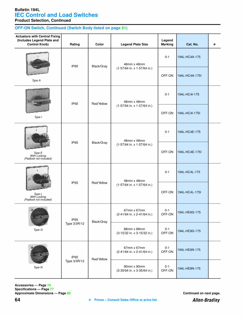
Bulletin 194L
IEC Control and Load Switches
64
Product Selection, Continued
OFF-ON Switch, Continued (Switch Body listed on page 61)
Actuators with Central Fixing(Includes Legend Plate and
Control Knob) Rating Color Legend Plate Size
Legend
Marking Cat. No. ❋
IP65 Black/Gray48mm x 48mm
(1-57/64 in. x 1-57/64 in.)
0-1 194L-HC4A-175
OFF-ON 194L-HC4A-175I
IP65 Red/Yellow48mm x 48mm
(1-57/64 in. x 1-57/64 in.)
0-1 194L-HC4I-175
OFF-ON 194L-HC4I-175I
IP65 Black/Gray48mm x 48mm
(1-57/64 in. x 1-57/64 in.)
0-1 194L-HC4E-175
OFF-ON 194L-HC4E-175I
IP65 Red/Yellow48mm x 48mm
(1-57/64 in. x 1-57/64 in.)
0-1 194L-HC4L-175
OFF-ON 194L-HC4L-175I
IP65
Type 3/3R/12Black/Gray
67mm x 67mm
(2-41/64 in. x 2-41/64 in.)
0-1
OFF-ON194L-HE6G-175
88mm x 88mm
(3-15/32 in. x 3-15/32 in.)
0-1
OFF-ON194L-HE8G-175
IP65
Type 3/3R/12Red/Yellow
67mm x 67mm
(2-41/64 in. x 2-41/64 in.)
0-1
OFF-ON194L-HE6N-175
90mm x 90mm
(3-35/64 in. x 3-35/64 in.)
0-1
OFF-ON194L-HE8N-175
Accessories — Page 74Specifications — Page 77
Approximate Dimensions — Page 80 Continued on next page.
Type A
Type I
Type EWith Locking
(Padlock not included)
Type LWith Locking
(Padlock not included)
Type G
Type N
❋ Prices – Consult Sales Office or price list
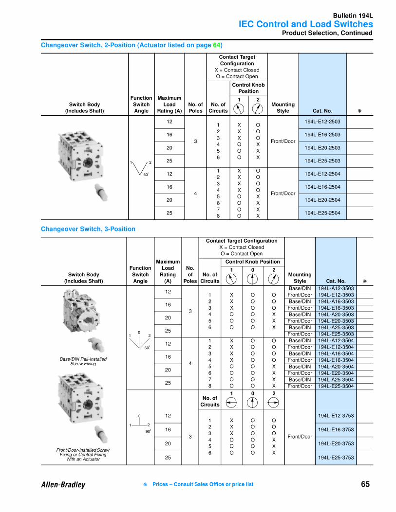
Bulletin 194L
IEC Control and Load Switches
65❋ Prices – Consult Sales Office or price list
Product Selection, Continued
Changeover Switch, 2-Position (Actuator listed on page 64)
Changeover Switch, 3-Position
Switch Body(Includes Shaft)
Function
Switch Angle
Maximum
Load Rating (A)
No. of Poles
Contact Target
Configuration
X = Contact Closed
O = Contact Open
Mounting Style Cat. No. ❋
No. of Circuits
Control Knob Position
1 2
12
3
1
2
3
4
5
6
X
X
X
O
O
O
O
O
O
X
X
X
Front/Door
194L-E12-2503
16 194L-E16-2503
20 194L-E20-2503
25 194L-E25-2503
12
4
1
2
3
4
5
6
7
8
X
X
X
X
O
O
O
O
O
O
O
O
X
X
X
X
Front/Door
194L-E12-2504
16 194L-E16-2504
20 194L-E20-2504
25 194L-E25-2504
Switch Body
(Includes Shaft)
Function
Switch
Angle
Maximum Load
Rating
(A)
No.
of
Poles
Contact Target Configuration
X = Contact Closed
O = Contact Open
Mounting
Style Cat. No. ❋
No. of
Circuits
Control Knob Position
1 0 2
12
3
1
2
3
4
5
6
X
X
X
O
O
O
O
O
O
O
O
O
O
O
O
X
X
X
Base/DIN 194L-A12-3503
Front/Door 194L-E12-3503
16Base/DIN 194L-A16-3503
Front/Door 194L-E16-3503
20Base/DIN 194L-A20-3503
Front/Door 194L-E20-3503
25Base/DIN 194L-A25-3503
Front/Door 194L-E25-3503
12
4
1
2
3
4
5
6
7
8
X
X
X
X
O
O
O
O
O
O
O
O
O
O
O
O
O
O
O
O
X
X
X
X
Base/DIN 194L-A12-3504
Front/Door 194L-E12-3504
16Base/DIN 194L-A16-3504
Front/Door 194L-E16-3504
20Base/DIN 194L-A20-3504
Front/Door 194L-E20-3504
25Base/DIN 194L-A25-3504
Front/Door 194L-E25-3504
No. of
Circuits
1 0 2
12
3
1
2
3
4
5
6
X
X
X
O
O
O
O
O
O
O
O
O
O
O
O
X
X
X
Front/Door
194L-E12-3753
16 194L-E16-3753
20 194L-E20-3753
25 194L-E25-3753
60
1 2
O
Base/DIN Rail-Installed Screw Fixing
Front/Door-Installed Screw Fixing or Central Fixing
With an Actuator
60
1 20
O
1 2
0
90O
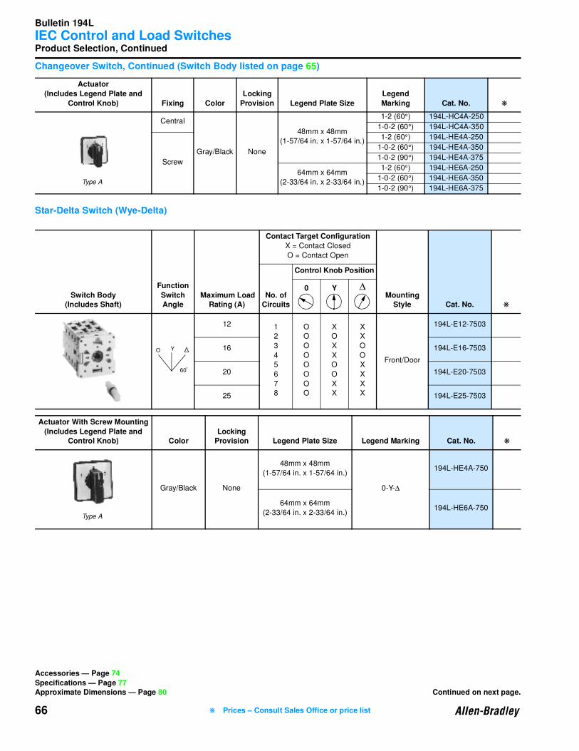
Bulletin 194L
IEC Control and Load Switches
66
Product Selection, Continued
Changeover Switch, Continued (Switch Body listed on page 65)
Star-Delta Switch (Wye-Delta)
Actuator
(Includes Legend Plate and
Control Knob) Fixing Color
Locking
Provision Legend Plate Size
Legend
Marking Cat. No. ❋
Central
Gray/Black None
48mm x 48mm
(1-57/64 in. x 1-57/64 in.)
1-2 (60°) 194L-HC4A-250
1-0-2 (60°) 194L-HC4A-350
Screw
1-2 (60°) 194L-HE4A-250
1-0-2 (60°) 194L-HE4A-350
1-0-2 (90°) 194L-HE4A-375
64mm x 64mm
(2-33/64 in. x 2-33/64 in.)
1-2 (60°) 194L-HE6A-250
1-0-2 (60°) 194L-HE6A-350
1-0-2 (90°) 194L-HE6A-375
Switch Body(Includes Shaft)
Function
Switch Angle
Maximum Load Rating (A)
Contact Target Configuration
X = Contact Closed
O = Contact Open
Mounting Style Cat. No. ❋
No. of Circuits
Control Knob Position
0 Y ∆
12 1
2
3
4
5
6
7
8
O
O
O
O
O
O
O
O
X
O
X
X
O
O
X
X
X
X
O
O
X
X
X
X
Front/Door
194L-E12-7503
16 194L-E16-7503
20 194L-E20-7503
25 194L-E25-7503
Actuator With Screw Mounting
(Includes Legend Plate and Control Knob) Color
Locking Provision Legend Plate Size Legend Marking Cat. No. ❋
Gray/Black None
48mm x 48mm
(1-57/64 in. x 1-57/64 in.)
0-Y-∆
194L-HE4A-750
64mm x 64mm
(2-33/64 in. x 2-33/64 in.)194L-HE6A-750
Type A
60
O Y
O
Accessories — Page 74
Specifications — Page 77Approximate Dimensions — Page 80 Continued on next page.
Type A
❋ Prices – Consult Sales Office or price list

Bulletin 194L
IEC Control and Load Switches
67❋ Prices – Consult Sales Office or price list
Product Selection, Continued
Reversing Switch
Ammeter Switch, 3∅ With Ground (Actuator listed on page 68)
Switch Body
(Includes Shaft)
Function
Switch
Angle
Maximum
Load
Rating (A)
Contact Target Configuration
X = Contact Closed
O = Contact Open
Mounting
Style Cat. No. ❋
No. of
Circuits
Control Knob Position
1 0 2
12
1
2
3
4
5
O
X
X
O
X
O
O
O
O
O
X
O
O
X
X
Front/
Door
194L-E12-7543
16 194L-E16-7543
20 194L-E20-7543
25 194L-E25-7543
Actuator
(Includes Legend Plate and Control Knob) Fixing Color
Locking Provision Legend Plate Size
Legend Marking Cat. No. ❋
Central
Gray/Black No
48mm x 48mm
(1-57/64 in. x 1-57/64 in.)1-0-2
194L-HC4A-350
Screw
194L-HE4A-350
64mm x 64mm
(2-33/64 in. x 2-33/64 in.)194L-HE6A-350
Switch Body(Includes Shaft)
Function
Switch Angle
Maximum
Load Rating (A)
Contact Target ConfigurationX = Contact Closed
O = Contact Open
Mounting Style Cat. No. ❋
No. of Circuits
Control Knob Position
0 1 2 3
12
1
2
3
4
5
6
7
O
O
X
X
O
O
X
X
O
O
O
O
O
X
O
O
O
X
O
X
O
O
X
X
O
O
O
X
Base/DIN 194L-A12-8751
Front/Door 194L-E12-8751
60
1 20
O
Type A
90
13
2
0
O
Accessories — Page 74
Specifications — Page 77Approximate Dimensions — Page 80
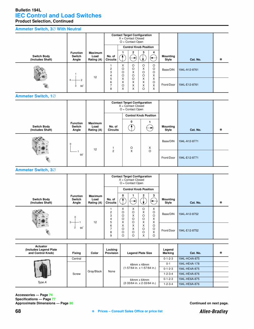
Bulletin 194L
IEC Control and Load Switches
68
Product Selection, Continued
Ammeter Switch, 3∅ With Neutral
Ammeter Switch, 1∅
Ammeter Switch, 3∅
Switch Body(Includes Shaft)
Function Switch Angle
Maximum Load
Rating (A)
Contact Target ConfigurationX = Contact ClosedO = Contact Open
Mounting Style Cat. No. ❋
No. of Circuits
Control Knob Position
1 2 3 4
12
12345678
XOOOXXOX
OOXOOXXX
OXOOXXXO
OOOXXOXX
Base/DIN 194L-A12-8761
Front/Door 194L-E12-8761
Switch Body(Includes Shaft)
Function Switch Angle
Maximum Load
Rating (A)
Contact Target ConfigurationX = Contact ClosedO = Contact Open
Mounting Style Cat. No. ❋
No. of Circuits
Control Knob Position
0 1
1212
OX
XO
Base/DIN 194L-A12-8771
Front/Door 194L-E12-8771
Switch Body(Includes Shaft)
Function Switch Angle
Maximum Load
Rating (A)
Contact Target ConfigurationX = Contact ClosedO = Contact Open
Mounting Style Cat. No. ❋
No. of Circuits
Control Knob Position
0 1 2 3
12
123456789
XOOOXXOOO
XOXOOXXOO
OXOOXXOOX
XOOXXOOXO
Base/DIN 194L-A12-8752
Front/Door 194L-E12-8752
Actuator(Includes Legend Plate
and Control Knob) Fixing ColorLocking
Provision Legend Plate SizeLegend Marking Cat. No. ❋
Central
Gray/Black None
48mm x 48mm(1-57/64 in. x 1-57/64 in.)
0-1-2-3 194L-HC4A-875
Screw
0-1 194L-HE4A-178
0-1-2-3 194L-HE4A-875
1-2-3-4 194L-HE4A-876
64mm x 64mm (2-33/64 in. x 2-33/64 in.)
0-1-2-3 194L-HE6A-875
1-2-3-4 194L-HE6A-876
90
4
3
2
1
O
0
90
1O
Accessories — Page 74
Specifications — Page 77Approximate Dimensions — Page 80 Continued on next page.
90
13
2
0
O
Type A
❋ Prices – Consult Sales Office or price list
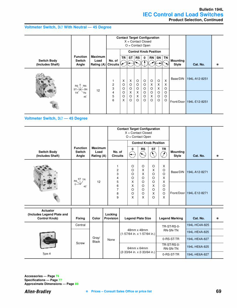
Bulletin 194L
IEC Control and Load Switches
69
Product Selection, Continued
Voltmeter Switch, 3∅ With Neutral — 45 Degree
Voltmeter Switch, 3∅ — 45 Degree
Switch Body(Includes Shaft)
Function
Switch Angle
Maximum
Load Rating (A)
Contact Target ConfigurationX = Contact Closed
O = Contact Open
Mounting Style Cat. No. ❋
No. of Circuits
Control Knob Position
TR ST RS 0 RN SN TN
12
1
2
3
4
5
6
X
O
O
O
O
X
X
O
O
X
O
O
O
O
O
X
X
O
O
O
O
O
O
O
O
X
O
O
X
O
O
X
X
O
O
O
X
X
O
O
O
O
Base/DIN 194L-A12-8251
Front/Door 194L-E12-8251
Switch Body
(Includes Shaft)
Function Switch
Angle
Maximum Load
Rating (A)
Contact Target Configuration
X = Contact Closed
O = Contact Open
Mounting
Style Cat. No. ❋
No. of
Circuits
Control Knob Position
0 RS ST TR
12
1
2
3
4
5
6
7
8
9
O
O
O
O
X
X
O
O
X
O
X
X
O
O
O
O
O
X
O
X
O
O
O
X
O
X
O
X
O
O
X
X
O
O
O
X
Base/DIN 194L-A12-8271
Front/Door 194L-E12-8271
Actuator(Includes Legend Plate and
Control Knob) Fixing Color
Locking
Provision Legend Plate Size Legend Marking Cat. No. ❋
Central
Gray/
BlackNone
48mm x 48mm
(1-57/64 in. x 1-57/64 in.)
TR-ST-RS-0-
RN-SN-TN
194L-HC4A-825
Screw
194L-HE4A-825
0-RS-ST-TR 194L-HE4A-827
64mm x 64mm
(2-33/64 in. x 2-33/64 in.)
TR-ST-RS-0-
RN-SN-TN194L-HE6A-825
0-RS-ST-TR 194L-HE6A-827
0 RN
SN
TN
45
RS
TR
ST
O
0
RSST TR
45O
Type A
Accessories — Page 74
Specifications — Page 77Approximate Dimensions — Page 80
❋ Prices – Consult Sales Office or price list
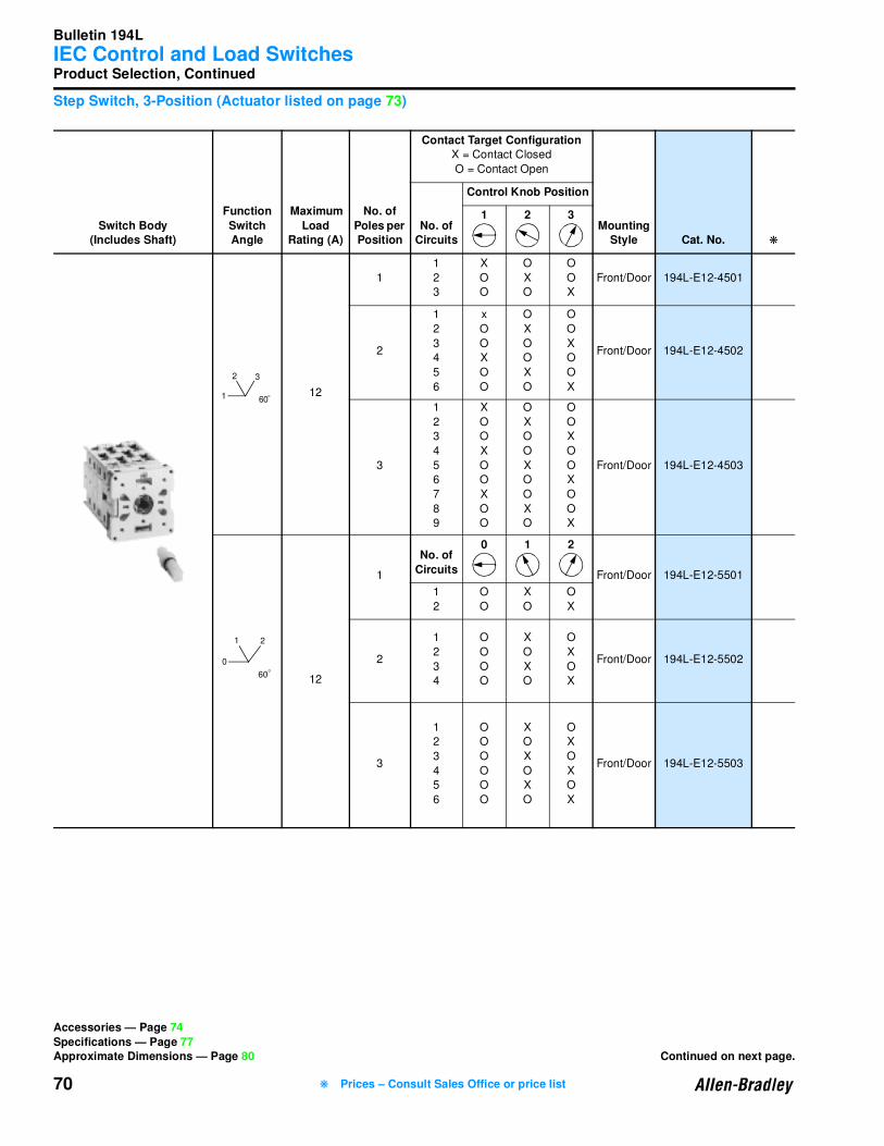
Bulletin 194L
IEC Control and Load Switches
70
Product Selection, Continued
Step Switch, 3-Position (Actuator listed on page 73)
Switch Body(Includes Shaft)
Function
Switch Angle
Maximum
Load Rating (A)
No. of
Poles per Position
Contact Target ConfigurationX = Contact Closed
O = Contact Open
Mounting Style Cat. No. ❋
No. of Circuits
Control Knob Position
1 2 3
12
1
1
2
3
X
O
O
O
X
O
O
O
X
Front/Door 194L-E12-4501
2
1
2
3
4
5
6
x
O
O
X
O
O
O
X
O
O
X
O
O
O
X
O
O
X
Front/Door 194L-E12-4502
3
1
2
3
4
5
6
7
8
9
X
O
O
X
O
O
X
O
O
O
X
O
O
X
O
O
X
O
O
O
X
O
O
X
O
O
X
Front/Door 194L-E12-4503
12
1
No. of
Circuits
0 1 2
Front/Door 194L-E12-5501
1
2
O
O
X
O
O
X
2
1
2
3
4
O
O
O
O
X
O
X
O
O
X
O
X
Front/Door 194L-E12-5502
3
1
2
3
4
5
6
O
O
O
O
O
O
X
O
X
O
X
O
O
X
O
X
O
X
Front/Door 194L-E12-5503
60
32
1 O
21
0
60O
Accessories — Page 74
Specifications — Page 77Approximate Dimensions — Page 80 Continued on next page.
❋ Prices – Consult Sales Office or price list

Bulletin 194L
IEC Control and Load Switches
71
Product Selection, Continued
Step Switch, 4-Position (Actuator listed on page 73)
Switch Body(Includes Shaft)
Function
Switch Angle
Maximum
Load Rating (A)
No. of
Poles per Position
Contact Target ConfigurationX = Contact Closed
O = Contact Open
Mounting Style Cat. No. ❋
No. of Circuits
Control Knob Position
1 2 3 4
12
1
1
2
3
4
X
O
O
O
O
X
O
O
O
O
X
O
O
O
O
X
Front/Door 194L-E12-4511
2
1
2
3
4
5
6
7
8
X
O
O
O
X
O
O
O
O
X
O
O
O
X
O
O
O
O
X
O
O
O
X
O
O
O
O
X
O
O
O
X
Front/Door 194L-E12-4512
3
1
2
3
4
5
6
7
8
9
10
11
12
X
O
O
O
X
O
O
O
X
O
O
O
O
X
O
O
O
X
O
O
O
X
O
O
O
O
X
O
O
O
X
O
O
O
X
O
O
O
O
X
O
O
O
X
O
O
O
X
Front/Door 194L-E12-4513
12
1
No. of
Circuits
0 1 2 3
Front/Door 194L-E12-55111
2
3
O
O
O
X
O
O
O
X
O
O
O
X
2
1
2
3
4
5
6
O
O
O
O
O
O
X
O
O
X
O
O
O
X
O
O
X
O
O
O
X
O
O
X
Front/Door 194L-E12-5512
3
1
2
3
4
5
6
7
8
9
O
O
O
O
O
O
O
O
O
X
O
O
X
O
O
X
O
O
O
X
O
O
X
O
O
X
O
O
O
X
O
O
X
O
O
X
Front/Door 194L-E12-5513
3
4
2
1
60O
2
3
1
0
60O
Accessories — Page 74Specifications — Page 77
Approximate Dimensions — Page 80
❋ Prices – Consult Sales Office or price list
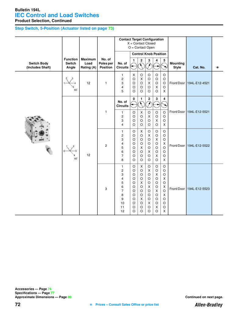
Bulletin 194L
IEC Control and Load Switches
72
Product Selection, Continued
Step Switch, 5-Position (Actuator listed on page 73)
Switch Body(Includes Shaft)
Function
Switch Angle
Maximum
Load Rating (A)
No. of
Poles per Position
Contact Target ConfigurationX = Contact Closed
O = Contact Open
Mounting Style Cat. No. ❋
No. of Circuits
Control Knob Position
1 2 3 4 5
12 1
1
2
3
4
5
X
O
O
O
O
O
X
O
O
O
O
O
X
O
O
O
O
O
X
O
O
O
O
O
X
Front/Door 194L-E12-4521
12
1
No. of
Circuits
0 1 2 3 4
Front/Door 194L-E12-55211
2
3
4
O
O
O
O
X
O
O
O
O
X
O
O
O
O
X
O
O
O
O
X
2
1
2
3
4
5
6
7
8
O
O
O
O
O
O
O
O
X
O
O
O
X
O
O
O
O
X
O
O
O
X
O
O
O
O
X
O
O
O
X
O
O
O
O
X
O
O
O
X
Front/Door 194L-E12-5522
3
1
2
3
4
5
6
7
8
9
10
11
12
O
O
O
O
O
O
O
O
O
O
O
O
X
O
O
O
X
O
O
O
X
O
O
O
O
X
O
O
O
X
O
O
O
X
O
O
O
O
X
O
O
O
X
O
O
O
X
O
O
O
O
X
O
X
O
X
O
O
O
X
Front/Door 194L-E12-5523
3
4
2
1
560
O
2
3
1
0
4
60O
Accessories — Page 74Specifications — Page 77
Approximate Dimensions — Page 80 Continued on next page.
❋ Prices – Consult Sales Office or price list
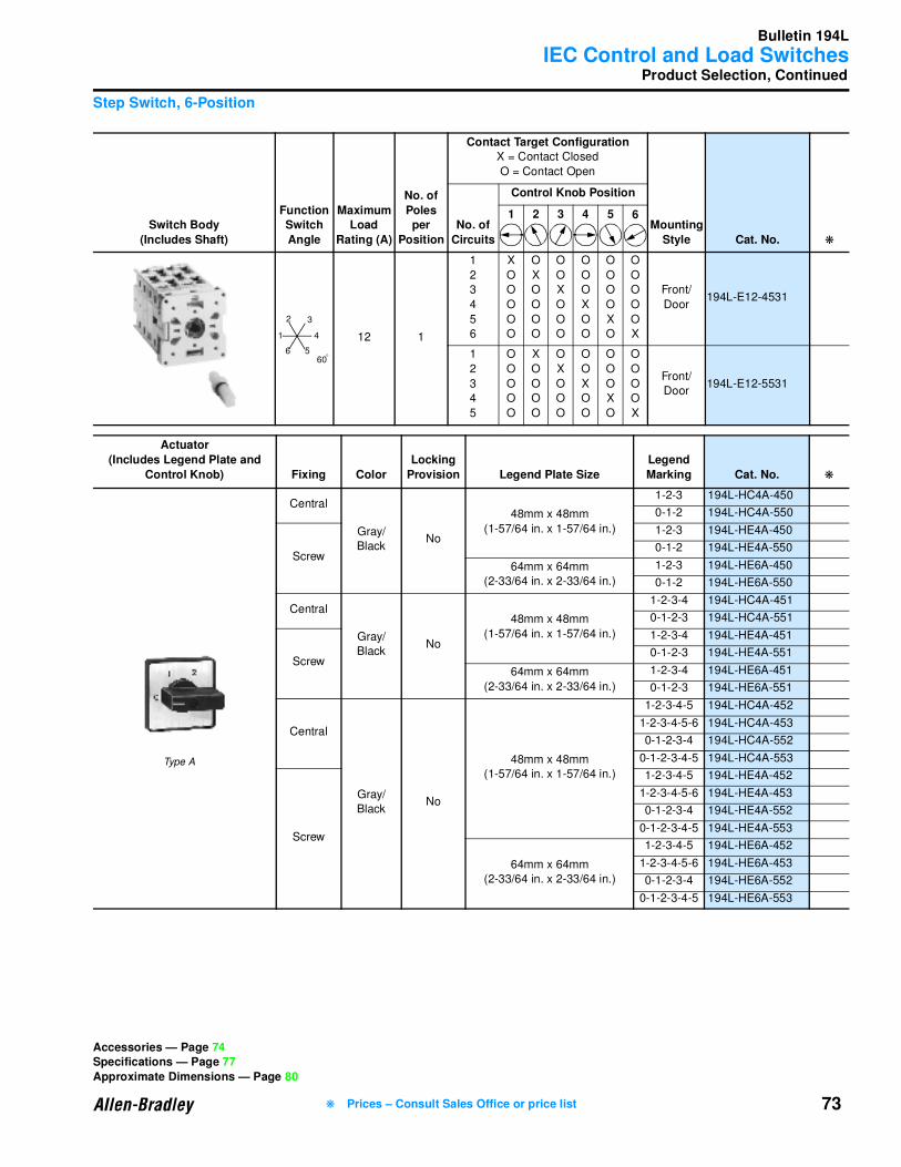
Bulletin 194L
IEC Control and Load Switches
73
Product Selection, Continued
Step Switch, 6-Position
Switch Body
(Includes Shaft)
Function Switch
Angle
Maximum Load
Rating (A)
No. of
Poles per
Position
Contact Target ConfigurationX = Contact Closed
O = Contact Open
Mounting
Style Cat. No. ❋
No. of
Circuits
Control Knob Position
1 2 3 4 5 6
12 1
1
2
3
4
5
6
X
O
O
O
O
O
O
X
O
O
O
O
O
O
X
O
O
O
O
O
O
X
O
O
O
O
O
O
X
O
O
O
O
O
O
X
Front/
Door194L-E12-4531
1
2
3
4
5
O
O
O
O
O
X
O
O
O
O
O
X
O
O
O
O
O
X
O
O
O
O
O
X
O
O
O
O
O
X
Front/
Door194L-E12-5531
Actuator
(Includes Legend Plate and
Control Knob) Fixing Color
Locking
Provision Legend Plate Size
Legend
Marking Cat. No. ❋
Central
Gray/
BlackNo
48mm x 48mm
(1-57/64 in. x 1-57/64 in.)
1-2-3 194L-HC4A-450
0-1-2 194L-HC4A-550
Screw
1-2-3 194L-HE4A-450
0-1-2 194L-HE4A-550
64mm x 64mm
(2-33/64 in. x 2-33/64 in.)
1-2-3 194L-HE6A-450
0-1-2 194L-HE6A-550
Central
Gray/
BlackNo
48mm x 48mm
(1-57/64 in. x 1-57/64 in.)
1-2-3-4 194L-HC4A-451
0-1-2-3 194L-HC4A-551
Screw
1-2-3-4 194L-HE4A-451
0-1-2-3 194L-HE4A-551
64mm x 64mm
(2-33/64 in. x 2-33/64 in.)
1-2-3-4 194L-HE6A-451
0-1-2-3 194L-HE6A-551
Central
Gray/
BlackNo
48mm x 48mm
(1-57/64 in. x 1-57/64 in.)
1-2-3-4-5 194L-HC4A-452
1-2-3-4-5-6 194L-HC4A-453
0-1-2-3-4 194L-HC4A-552
0-1-2-3-4-5 194L-HC4A-553
Screw
1-2-3-4-5 194L-HE4A-452
1-2-3-4-5-6 194L-HE4A-453
0-1-2-3-4 194L-HE4A-552
0-1-2-3-4-5 194L-HE4A-553
64mm x 64mm
(2-33/64 in. x 2-33/64 in.)
1-2-3-4-5 194L-HE6A-452
1-2-3-4-5-6 194L-HE6A-453
0-1-2-3-4 194L-HE6A-552
0-1-2-3-4-5 194L-HE6A-553
3
6
4
2
1
560
O
Accessories — Page 74Specifications — Page 77
Approximate Dimensions — Page 80
Type A
❋ Prices – Consult Sales Office or price list

Bulletin 194L
IEC Control and Load Switches
74
Accessories
➊ Covers must be drilled for operating handle by user.
Use With
Switch
Number of
Contacts
ABS
Required
Shaft
❋
Noryl Material
Required
Shaft
❋Cat. No. Cat. No.
194L-A12/16
1, 2 194L-G3572 194L-G3195 194L-G3576 194L-G3195
3, 4 194L-G3572 194L-G2830 194L-G3576 194L-G2830
5, 6 194L-G3573 194L-G3195 194L-G3577 194L-G3195
194L-A20/25
1, 2 194L-G3572 194L-G3194 194L-G3576 194L-G3194
3, 4 194L-G3572 194L-G2830 194L-G3576 194L-G2830
5, 6 194L-G3573 194L-G3194 194L-G3577 194L-G3194
194E-E12/161, 4 194L-G3574 ➊ 194L-G3380 194L-G3578 ➊ 194L-G3380
5, 6 194L-G3575 ➊ 194L-G3380 194L-G3579 ➊ 194L-G3380
194E-E20/251, 4 194L-G3574 ➊ 194L-G3380 194L-G3578 ➊ 194L-G3380
5, 6, 7, 8 194L-G3575 ➊ 194L-G3380 194L-G3579 ➊ 194L-G3380
Accessory Description
Pkg.
Qty. Cat. No. ❋
Use 800E Legend Frames and Inserts
See page 11-170 of A112 Catalog— —
Blank Legend Plate, 48mm x 48mm (1-57/64 in. x 1-57/64 in.)
10
194L-B4
Blank Legend Plate, 64mm x 64mm (2-33/64 in. x 2-33/64 in.) 194L-B6
Use With Size 6 Handles
Product Selection — Page 61 Continued on next page.
❋ Prices – Consult Sales Office or price list
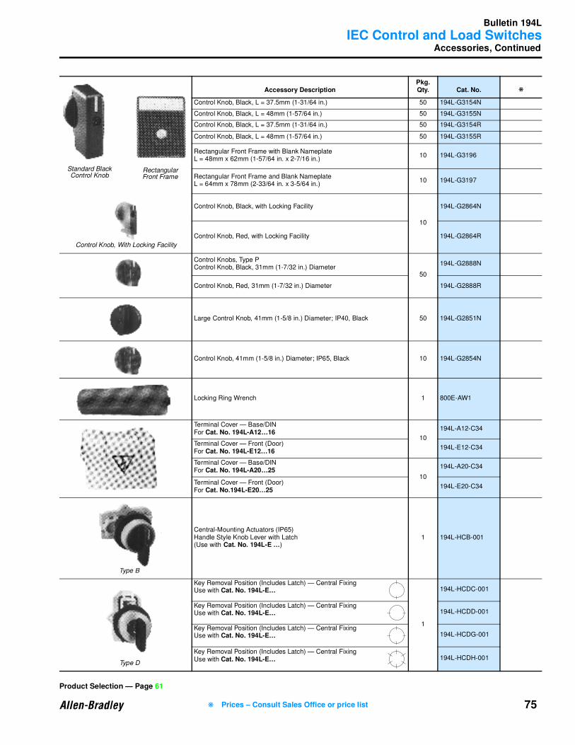
Bulletin 194L
IEC Control and Load Switches
75
Accessories, Continued
Accessory DescriptionPkg. Qty. Cat. No. ❋
Control Knob, Black, L = 37.5mm (1-31/64 in.) 50 194L-G3154N
Control Knob, Black, L = 48mm (1-57/64 in.) 50 194L-G3155N
Control Knob, Black, L = 37.5mm (1-31/64 in.) 50 194L-G3154R
Control Knob, Black, L = 48mm (1-57/64 in.) 50 194L-G3155R
Rectangular Front Frame with Blank Nameplate L = 48mm x 62mm (1-57/64 in. x 2-7/16 in.)
10 194L-G3196
Rectangular Front Frame and Blank Nameplate L = 64mm x 78mm (2-33/64 in. x 3-5/64 in.)
10 194L-G3197
Control Knob, Black, with Locking Facility
10
194L-G2864N
Control Knob, Red, with Locking Facility 194L-G2864R
Control Knobs, Type PControl Knob, Black, 31mm (1-7/32 in.) Diameter
50
194L-G2888N
Control Knob, Red, 31mm (1-7/32 in.) Diameter 194L-G2888R
Large Control Knob, 41mm (1-5/8 in.) Diameter; IP40, Black 50 194L-G2851N
Control Knob, 41mm (1-5/8 in.) Diameter; IP65, Black 10 194L-G2854N
Locking Ring Wrench 1 800E-AW1
Terminal Cover — Base/DINFor Cat. No. 194L-A12…16
10
194L-A12-C34
Terminal Cover — Front (Door)For Cat. No. 194L-E12…16
194L-E12-C34
Terminal Cover — Base/DINFor Cat. No. 194L-A20…25
10
194L-A20-C34
Terminal Cover — Front (Door)For Cat. No.194L-E20…25
194L-E20-C34
Central-Mounting Actuators (IP65)Handle Style Knob Lever with Latch(Use with Cat. No. 194L-E …)
1 194L-HCB-001
Key Removal Position (Includes Latch) — Central FixingUse with Cat. No. 194L-E…
1
194L-HCDC-001
Key Removal Position (Includes Latch) — Central FixingUse with Cat. No. 194L-E… 194L-HCDD-001
Key Removal Position (Includes Latch) — Central FixingUse with Cat. No. 194L-E… 194L-HCDG-001
Key Removal Position (Includes Latch) — Central FixingUse with Cat. No. 194L-E… 194L-HCDH-001
Standard BlackControl Knob
Rectangular Front Frame
Control Knob, With Locking Facility
Type B
Type D
Product Selection — Page 61
❋ Prices – Consult Sales Office or price list
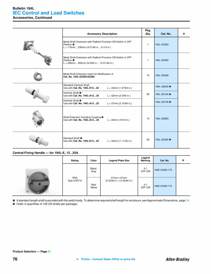
Bulletin 194L
IEC Control and Load Switches
76
Accessories, Continued
Central-Fixing Handle — for 194L-E, 12...25A
➊ A standard-length shaft is provided with the switch body. To determine required shaft length for enclosure, see Approximate Dimensions, page 84.
➋ Order in quantities of 100 (50 shafts per package).
Accessory Description
Pkg.
Qty. Cat. No. ❋
Metal Shaft Extension with Padlock Provision ON Switch in OFF Position ➊
L = 110mm…235mm (4-21/64 in.…9-1/4 in.)1 194L-G3393
Metal Shaft Extension with Padlock Provision ON Switch in OFF Position ➊
L = 230mm…350mm (9-3/64 in.…13-51/64 in.)1 194L-G3394
Metal Shaft Extension Insert for Modification of Cat. No. 194L-G3393/G3394
10 194L-G3399
Standard Interlock Shaft Use with Cat. No. 194L-E12…25 L = 44mm (1-47/64 in.)
50
194L-G2830 ➋
Interlock Shaft ➊Use with Cat. No. 194L-A12…25 L = 52mm (2-3/64 in.)
194L-G3194 ➋
Interlock Shaft ➊Use with Cat. No. 194L-A12…25 L = 57mm (2-15/64 in.)
194L-G3195 ➋
Shaft Extension Including Coupling ➊Use with Cat. No. 194L-A12…25 L = 24mm (15/16 in.)
10 194L-G2853
Standard Shaft ➊Use with Cat. No. 194L-E12…25 L = 34mm (1-11/32 in.)
50 194L-G3380 ➋
Rating Color Legend Plate SizeLegend Marking Cat. No. ❋
IP65Type 3/3R/12
Black/Gray
67mm x 67mm(2-33/64 in. x 2-33/64 in.)
0-1OFF-ON
194E-HC6G-175
Red/Yellow
0-1OFF-ON
194E-HC6N-175
Product Selection — Page 61
❋ Prices – Consult Sales Office or price list
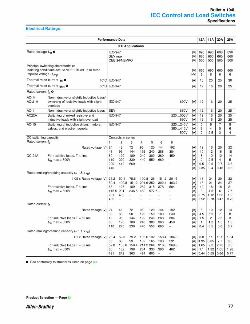
Bulletin 194L
IEC Control and Load Switches
77
Specifications
Electrical Ratings
➊ See conformity to standards listed on page 59.
Performance Data 12A 16A 20A 25A
IEC Applications
Rated voltage Ue ➊ IEC-947
SEV max.
CEE 24/NEMKO
[V]
[V]
[V]
690
660
500
690
660
500
690
660
500
690
660
500
Principal switching characteristics
Isolating conditions acc. to VDE fulfilled up to rated
impulse voltage Uimp
[V]
[kV]
660
6
690
6
660
6
660
6
Thermal rated current Ith ➊ 40°C IEC-947 [A] 16 20 25 30
Thermal rated current Ithe ➊ 60°C IEC-947 [A] 12 16 20 25
Rated current Ie ➊
AC-1/
AC-21A
Non-inductive or slightly inductive loads/
switching of resistive loads with slight
overload
IEC-947 690V [A] 12 16 20 25
AC-1 Non-inductive or slightly inductive loads SEV 660V [A] 12 16 20 25
AC22A Switching of mixed resistive and
inductive loads with slight overload
IEC-947 220…500V
690V
[A]
[A]
12
12
16
16
20
20
25
25
AC-15 Switching of inductive drives, motors,
valves, and electromagnets.
IEC-947 220…240V
380…415V
500V
[A]
[A]
[A]
5
3
2
6
4
2.5
7
5
3
8
6
4
DC switching capacity
Rated current Ie
Contacts in series
1 2 3 4 5 6 8
DC-21A
Rated voltage [V]
For resistive loads, T ≤ 1ms
Ue max = 600V
24 48 72 96 120 144 192
48 96 144 192 240 288 384
60 120 180 240 300 360 450
110 220 330 440 550 660 –
220 440 660 – – – –
440 – – – – – –
[A]
[A]
[A]
[A]
[A]
[A]
12
10
8
2
0.5
0.35
16
12
10
2.5
0.6
0.4
20
16
12
4
0.7
0.45
22
18
14
5
0.8
0.6
Rated making/breaking capacity (= 1.5 x Ie)
1.05 x Rated voltage [V]
For resistive loads, T ≤ 1ms
Ue max = 600V
25.2 50.4 75.6 100.8 126 151.2 201.6
50.4 100.8 151.2 201.6 252 302.4 403.2
63 126 189 252 315 378 504
115.5 231 346.5 462 577.5 – –
231 462 – – – – –
462 – – – – – –
[A]
[A]
[A]
[A]
[A]
[A]
18
15
12
3
0.75
0.52
24
21
18
4.5
1.12
0.78
30
24
18
6
1.05
0.47
33
27
21
7.5
1.2
0.75
Rated current Ie
Rated voltage [V]
For inductive loads T = 50 ms
Ue max = 600V
24 48 72 96 120 144 192
30 60 90 120 150 180 240
48 96 144 192 240 288 384
60 120 180 240 300 360 450
110 220 330 440 550 660 –
[A]
[A]
[A]
[A]
[A]
8
4.5
1.5
1
0.4
10
5.5
2
1.2
0.5
12
7
2.5
1.5
0.6
14
8
3
1.8
0.7
Rated making/breaking capacity (= 1.1 x Ie)
1.1 x Rated voltage [V]
For inductive loads T = 50 ms
Ue max = 600V
26.4 52.8 79.2 105.6 132 158.4 184.8
33 66 99 132 165 198 231
52.8 105.6 158.4 211.2 264 316.8 369.6
66 132 198 264 330 396 462
121 242 363 484 605 – –
[A]
[A]
[A]
[A]
[A]
8.8
4.95
1.65
1.1
0.44
11
6.05
2.2
1.32
0.55
13.2
7.7
2.75
1.65
0.66
1.54
8.8
3.3
1.98
0.77
Product Selection — Page 61

Bulletin 194L
IEC Control and Load Switches
78
Specifications, Continued
➊ See conformity to standards listed on page 59.
Performance Data 12A 16A 20A 25A
IEC Applications
Rated power Pe Contacts in series
Rated voltage [V]
DC-23A, DC-3, DC-5
For inductive loads, T ≤1 ms
24
24
48
48
60
60
110
110
220
220
1
2
2
3
2
4
4
6
4
6
[kW]
[kW]
[kW]
[kW]
[kW]
[kW]
[kW]
[kW]
[kW]
[kW]
0.12
0.20
0.25
0.30
0.25
0.37
0.50
1.00
0.37
1.00
0.15
0.25
0.30
0.37
0.30
0.50
0.75
1.20
0.50
1.20
0.20
0.30
0.37
0.50
0.37
0.75
1.00
1.40
0.75
1.40
0.25
0.37
0.50
0.75
0.50
1.00
1.20
1.60
1.00
1.50
Rated making/breaking capacity (= 4 x Ie) Contacts in series
Rated voltage [V]
DC-23A, DC-3, DC-5
For inductive loads, T ≤ 15 ms
25.2
25.2
50.4
50.4
63
63
115.5
115.5
231
231
1
2
2
3
2
4
4
6
4
6
[A]
[A]
[A]
[A]
[A]
[A]
[A]
[A]
[A]
[A]
20.0
33.3
21.0
25.0
16.6
24.6
18.1
36.4
6.7
18.1
25.0
41.6
25.0
30.8
20.0
33.3
27.2
43.6
9.1
21.8
33.3
50.0
30.8
42.0
24.6
50.0
36.4
51.0
13.6
25.2
41.6
61.6
41.6
62.4
33.2
66.4
44.0
58.2
18.2
27.2
Rated breaking capacity at 220V
at 380V
at 660V
[A]
[cos ϕ]
[A]
[cos ϕ]
[A]
[cos ϕ]
72
0.65
72
0.65
53
0.65
96
0.65
96
0.65
72
0.65
128
0.65
128
0.65
86
0.65
176
0.35
176
0.35
112
0.65
Rated power Pe ➊ IEC-947
AC-2 Slip-ring motors: starting, reversing
and electric braking; star/delta
starting 3 ∅
3-pole
240V
380V
415V
440V
500V
660V
[kW]
[kW]
[kW]
[kW]
[kW]
[kW]
3
5.5
5.5
5.5
7.5
7.5
4
7.5
7.5
7.5
10
10
5.5
9
9
9
11
11
5.5
13
13
13
15
15
AC-3 Squirrel-cage motors: starting and
stopping of running motors
IEC-947
3 ∅
3-pole
220…240V
380…440V
500V
660V
[kW]
[kW]
[kW]
[kW]
2.2
4
5.5
5.5
3
5.5
7.5
7.5
4.5
7.5
10
8
5.5
11
13
11
1 ∅
2-pole
110V
220…240V
380…440V
[kW]
[kW]
[kW]
0.75
1.3
2.2
1.1
2.2
3.7
1.2
2.5
4.5
1.6
3.2
5.5
AC-4 Squirrel-cage motors: starting,
reversing, electric braking, inching
IEC-947
3 ∅
3-pole
220…240V
380…415V
440…550V
[kW]
[kW]
[kW]
0.75
1.5
1.5
1.5
2.2
2.2
3
3.7
3.7
4
5.5
5.5
1 ∅
2-pole
110V
240V
380V
440V
[kW]
[kW]
[kW]
[kW]
0.18
0.37
0.75
0.75
0.37
0.75
1.1
1.1
0.55
1.5
1.8
1.8
0.75
2.2
3
3
Product Selection — Page 61 Continued on next page.
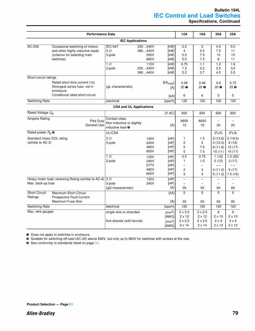
Bulletin 194L
IEC Control and Load Switches
79
Specifications, Continued
➊ Does not apply to switches in enclosure.
➋ Suitable for switching off-load (AC-20) above 660V, but only up to 660V for switches with screws at the rear.
➌ See conformity to standards listed on page 59.
Performance Data 12A 16A 20A 25A
IEC Applications
AC-23A Occasional switching of motors
and other highly inductive loads
(criterion for selecting main
switches)
IEC-947
3 ∅
3-pole
220…240V
380…440V
500V
660V
[kW]
[kW]
[kW]
[kW]
2.2
4
5.5
5.5
3
5.5
7.5
7.5
4.5
7.5
10
8
5.5
11
13
11
1 ∅
2-pole
110V
220…240V
380…440V
[kW]
[kW]
[kW]
0.75
1.3
2.2
1.1
2.2
3.7
1.2
2.5
4.5
1.6
3.2
5.5
Short-circuit ratings
Rated short-time current (1s)
Strongest series fuse, not in
enclosure
Conditional rated short-circuit
(gL characteristic)
[kArms]
[A]
[kA]
0.48
20 ➊
6
0.48
20 ➊
6
0.6
20 ➊
5
0.75
25 ➋
5
Switching Rate electrical [ops/h] 120 120 120 120
CSA and UL Applications
Rated Voltage Ue [V AC] 600 600 600 600
Ampere RatingPilot Duty
General Use
Contact class
Non-inductive or slightly
inductive load ➋[A]
A600
12
A600
16
–
20
–
25
Rated power Pe ➌ UL/CSA (FLA) (FLA)
Standard motor DOL rating
(similar to AC-3)
3 ∅
3-pole120V
240V
480V
600V
[HP]
[HP]
[HP]
[HP]
1
2
5
5
1.5
3
7.5
7.5
2 (13.6)
4 (12.4)
8 (11.6)
10 (11)
3 (19.2)
6 (18)
12 (17)
15 (17)
1 ∅
2-pole120V
240V
277V
480V
600V
[HP]
[HP]
[HP]
[HP]
[HP]
0.5
1
–
2
3
0.75
1.5
–
3
3
1 (16)
2 (12)
– –
4 (11.2)
5 (11.2)
1.5 (20)
3 (17)
– –
6 (17)
7.5 (16)
Heavy motor load, reversing Rating (similar to AC-4)
Max. back-up fuse
3 ∅
3-pole
(gG characteristic)
120V
240V
[HP]
[HP]
[A]
–
–
35
–
–
55
–
–
60
–
–
80
Short Circuit
RatingsMaximum Short Circuit
Prospective Fault Current
Maximum Fuse Size
[kA]
[A]
5
35
5
55
5
60
5
80
Switching Rate electrical [ops/h] 120 120 120 120
Max. wire gauges single wire or stranded
fine strands (with ferrule)
[mm2]
[AWG]
[mm2]
[AWG]
2 x 2.5
2 x 12
2 x 2.5
2 x 14
2 x 2.5
2 x 12
2 x 2.5
2 x 14
6
2 x 10
2 x 4
2 x 12
6
2 x 10
2 x 4
2 x 12
Product Selection — Page 61
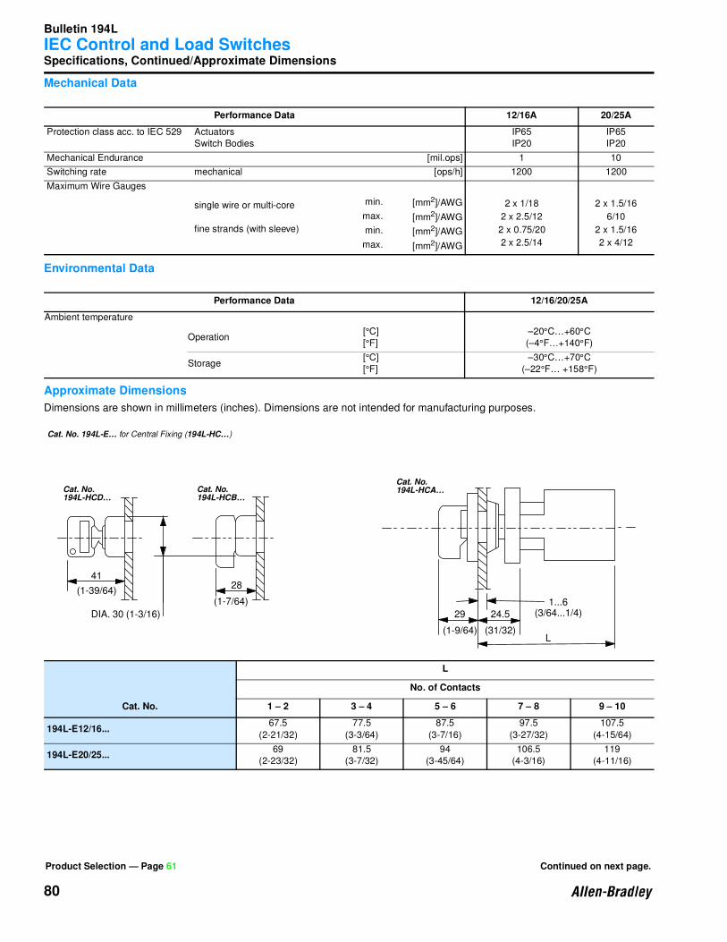
Bulletin 194L
IEC Control and Load Switches
80
Specifications, Continued/Approximate Dimensions
Mechanical Data
Environmental Data
Approximate Dimensions
Dimensions are shown in millimeters (inches). Dimensions are not intended for manufacturing purposes.
Performance Data 12/16A 20/25A
Protection class acc. to IEC 529 Actuators
Switch Bodies
IP65
IP20
IP65
IP20
Mechanical Endurance [mil.ops] 1 10
Switching rate mechanical [ops/h] 1200 1200
Maximum Wire Gauges
single wire or multi-core
fine strands (with sleeve)
min.
max.
min.
max.
[mm2]/AWG
[mm2]/AWG
[mm2]/AWG
[mm2]/AWG
2 x 1/18
2 x 2.5/12
2 x 0.75/20
2 x 2.5/14
2 x 1.5/16
6/10
2 x 1.5/16
2 x 4/12
Performance Data 12/16/20/25A
Ambient temperature
Operation[°C]
[°F]
–20°C…+60°C
(–4°F…+140°F)
Storage[°C]
[°F]
–30°C…+70°C
(–22°F… +158°F)
Cat. No.
L
No. of Contacts
1 – 2 3 – 4 5 – 6 7 – 8 9 – 10
194L-E12/16...67.5
(2-21/32)
77.5
(3-3/64)
87.5
(3-7/16)
97.5
(3-27/32)
107.5
(4-15/64)
194L-E20/25...69
(2-23/32)
81.5
(3-7/32)
94
(3-45/64)
106.5
(4-3/16)
119
(4-11/16)
Product Selection — Page 61 Continued on next page.
Central Fixing (194L-HC . . . )
94L-HCD. . . 194L-HCB. . .
194L-HC4A. . .
41
(1-39/64)28
(1-7/64)
DIA. 30 (1-3/16)
L
29
(1-9/64)
24.5
(31/32)
1...6(3/64...1/4)
Cat. No.
Cat. No.
at. No.
Cat. No. 194L-E… for Central Fixing (194L-HC…)
Cat. No.
194L-HCD…
Cat. No.
194L-HCB…
Cat. No.
194L-HCA…

Bulletin 194L
IEC Control and Load Switches
81
Approximate Dimensions, Continued
Dimensions are shown in millimeters (inches). Dimensions are not intended for manufacturing purposes.
Control Knob
Cat. No.
L
No. of Contacts
1 – 2 3 – 4 5 – 6 7 – 8 9 – 10
194L-E12/16...44
(1-47/64)
54
(2-1/8)
64
(2-33/64)
74
(2-29/32)
84
(3-5/16)
194L-E20/25...44.5
(1-3/4)
57
(2-1/4)
69.5
(2-3/4)
82
(3-15/64)
94.5
(3-23/32)
Cat. No. P Q
194L-HE4A...
28 (1-7/64)
48 (1-57/64) x 48 (1-57/64)194L-HE4I...
194L-HE4S... 48 (1-57/64) x 62 (2-7/16)
194L-HE6A...64 (2-33/64) x 64 (2-33/64)
194L-HE6I...
194L-HE6S... 64 (2-33/64) x 78 (3-5/64)
194L-HE6N...34 (1-11/32) 67 (2-41/64) x 67 (2-41/64)
194L-HE6G...
Cat. No. 194L-E 20/25…
Q
P L
1...5(3/64...13/64)
42 x 40(1-21/32 x 1-37/64)
50 x 49(1-31/32 x 1-15/16)
Q
P1...5
(3/64...13/64)
Cat. No.
194L-E 12/16…
Cat. No.
194L-E 20/25…
55 x 55(2-11/64 x 2-11/64)
DIA. 3.3 (1/8)
9.5 (3/8)32 (1-17/64) [28] (1-7/64)36 x 36 (1-27/64 x 1-27/64)48 x 48 (1-57/64 x 1-57/64)
Cat. No. 194L… for Front (Door) Installation
DIA. 3.3 (1/8)
42 x 42(1-21/32 x 1-21/32)
9.5 (3/8)
32 (1-17/64)36 x 36 (1-27/64 x 1-27/64)
[28] (1-7/64)
Cat. No. 194L-E 12/16…
Product Selection — Page 61
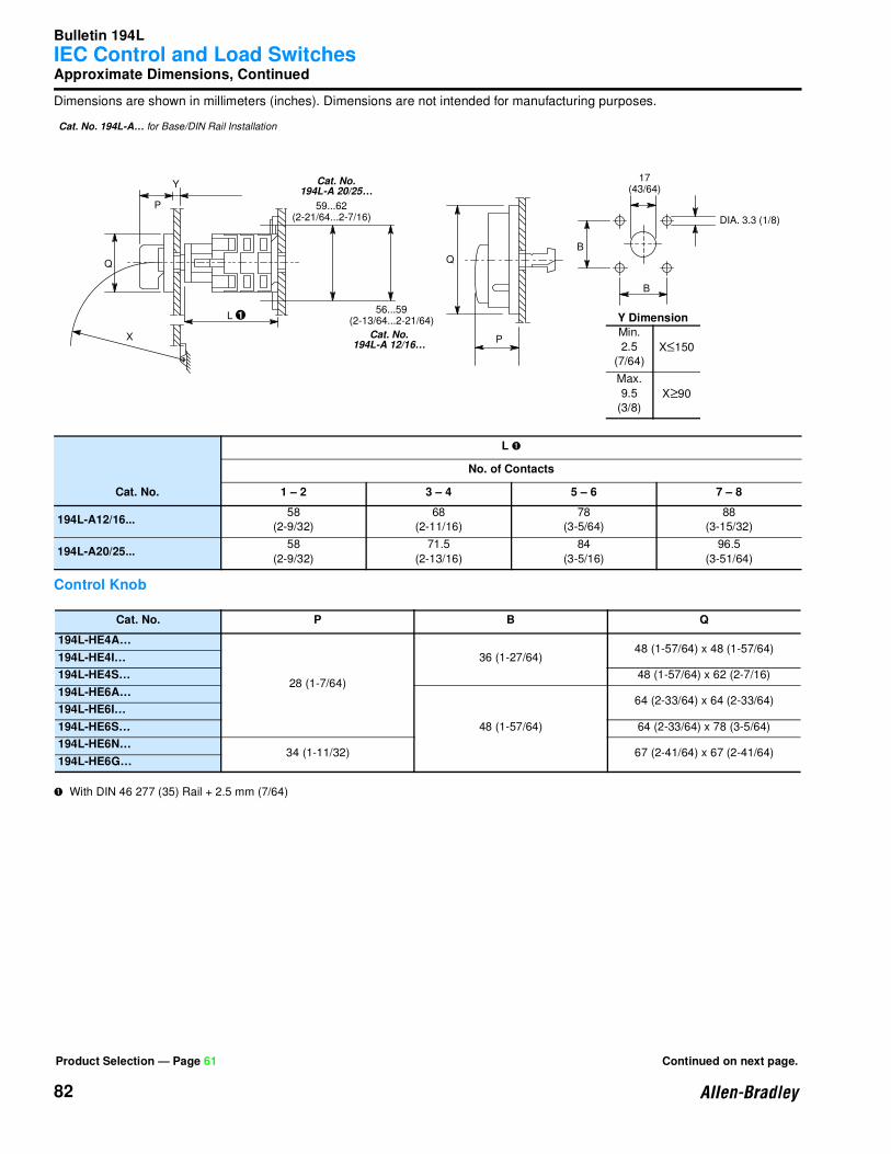
Bulletin 194L
IEC Control and Load Switches
82
Approximate Dimensions, Continued
Dimensions are shown in millimeters (inches). Dimensions are not intended for manufacturing purposes.
Control Knob
➊ With DIN 46 277 (35) Rail + 2.5 mm (7/64)
Cat. No.
L ➊
No. of Contacts
1 – 2 3 – 4 5 – 6 7 – 8
194L-A12/16...58
(2-9/32)
68
(2-11/16)
78
(3-5/64)
88
(3-15/32)
194L-A20/25...58
(2-9/32)
71.5
(2-13/16)
84
(3-5/16)
96.5
(3-51/64)
Cat. No. P B Q
194L-HE4A…
28 (1-7/64)
36 (1-27/64)48 (1-57/64) x 48 (1-57/64)
194L-HE4I…
194L-HE4S… 48 (1-57/64) x 62 (2-7/16)
194L-HE6A…
48 (1-57/64)
64 (2-33/64) x 64 (2-33/64)194L-HE6I…
194L-HE6S… 64 (2-33/64) x 78 (3-5/64)
194L-HE6N…34 (1-11/32) 67 (2-41/64) x 67 (2-41/64)
194L-HE6G…
Q
X
L
Q
P
B
B
17(43/64)
DIA. 3.3 (1/8)
P
Y
59...62(2-21/64...2-7/16)
56...59(2-13/64...2-21/64)
1 Y DimensionMin.
2.5
(7/64)X≤150
Max.
9.5
(3/8)X≥90
Cat. No. 194L-A… for Base/DIN Rail Installation
Cat. No.
194L-A 20/25…
Cat. No.
194L-A 12/16…
Product Selection — Page 61 Continued on next page.
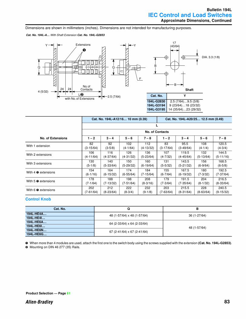
Bulletin 194L
IEC Control and Load Switches
83
Approximate Dimensions, Continued
Dimensions are shown in millimeters (inches). Dimensions are not intended for manufacturing purposes.
Control Knob
➊ When more than 4 modules are used, attach the first one to the switch body using the screws supplied with the extension (Cat. No. 194L-G2853).
➋ Mounting on DIN 46 277 (35) Rails.
No. of Extensions
Cat. No. 194L-A12/16… 10 mm (0.39) Cat. No. 194L-A20/25… 12.5 mm (0.49)
L
No. of Contacts
1 – 2 3 – 4 5 – 6 7 – 8 1 – 2 3 – 4 5 – 6 7 – 8
With 1 extension82
(3-15/64)
92
(3-5/8)
102
(4-1/64)
112
(4-13/32)
83
(3-17/64)
95.5
(3-49/64)
108
(4-1/4)
120.5
(4-3/4)
With 2 extensions106
(4-11/64)
116
(4-37/64)
126
(4-31/32)
136
(5-23/64)
107
(4-7/32)
119.5
(4-45/64)
132
(5-13/64)
144.5
(5-11/16)
With 3 extensions130
(5-1/8)
140
(5-33/64)
150
(5-29/32)
160
(6-19/64)
131
(5-5/32)
143.5
(5-21/32)
156
(6-9/64)
168.5
(6-5/8)
With 4 ➊ extensions154
(6-1/16)
164
(6-15/32)
174
(6-55/64)
184
(7-15/64)
155
(6-7/64)
167.5
(6-19/32)
180
(7-3/32)
192.5
(7-37/64)
With 5 ➊ extensions178
(7-1/64)
188
(7-13/32)
198
(7-51/64)
208
(8-3/16)
179
(7-3/64)
191.5
(7-35/64)
204
(8-1/32)
216.5
(8-33/64)
With 6 ➊ extensions202
(7-61/64)
212
(8-23/64)
222
(8-3/4)
232
(9-1/8)
203
(7-63/64)
215.5
(8-31/64)
228
(8-63/64)
240.5
(9-15/32)
Cat. No. Q B
194L-HE4A…48 (1-57/64) x 48 (1-57/64) 36 (1-27/64)
194L-HE4I…
194L-HE6A…64 (2-33/64) x 64 (2-33/64)
48 (1-57/64)194L-HE6I…
194L-HE6N…67 (2-41/64) x 67 (2-41/64)
194L-HE6G…
Y Y
24 24
L
with No. of Extensions
4 (5/32)
Extensions
2.5 (7/64)
F
B
B
17(43/64)
DIA. 3.3 (1/8)
1
2
No. ofContacts
Cat. No. 194L-A… With Shaft Extension Cat. No. 194L-G2853
Shaft
Cat. No. Y
194L-G2830194L-G3194
194L-G3195
2.5 (7/64)…9.5 (3/8)
9 (23/64)…18 (23/32)
14 (35/64)…23 (29/32)
Product Selection — Page 61
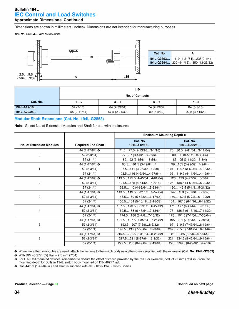
Bulletin 194L
IEC Control and Load Switches
84
Approximate Dimensions, Continued
Dimensions are shown in millimeters (inches). Dimensions are not intended for manufacturing purposes.
Modular Shaft Extensions (Cat. No. 194L-G2853)
Note: Select No. of Extension Modules and Shaft for use with enclosures.
➊ When more than 4 modules are used, attach the first one to the switch body using the screws supplied with the extension (Cat. No. 194L-G2853).
➋ With DIN 46 277 (35) Rail + 2.5 mm (7/64)
➌ For DIN Rail-mounted devices, remember to deduct the offset distance provided by the rail. For example, deduct 2.5mm (7/64 in.) from the mounting depth for Bulletin 194L switch body mounted on DIN 46277 rail.
➍ One 44mm (1-47/64 in.) end shaft is supplied with all Bulletin 194L Switch Bodies.
Cat. No.
L ➊
No. of Contacts
1 – 2 3 – 4 5 – 6 7 – 8
194L-A12/16... 54 (2-1/8) 64 (2-33/64) 74 (2-29/32) 84 (3-5/16)
194L-A20/25... 55 (2-11/64) 67.5 (2-21/32) 80 (3-5/32) 92.5 (3-41/64)
No. of Extension Modules Required End Shaft
Enclosure Mounting Depth ➌
Cat. No.194L-A12/16…
Cat. No.194L-A20/25…
0
44 (1-47/64) ➍ 71.5…77.5 (2-13/16…3-1/16) 75…80.5 (2-61/64…3-11/64)
52 (2-3/64) 77…87 (3-1/32…3-27/64) 80…90 (3-5/32…3-35/64)
57 (2-1/4) 82…92 (3-15/64…3-5/8) 85…95 (3-11/32…3-3/4)
1
44 (1-47/64) ➍ 95.5…101.5 (3-49/64…4) 99…105 (3-29/32…4-9/64)
52 (2-3/64) 97.5…111 (3-27/32…4-3/8) 101…114.5 (3-63/64…4-33/64)
57 (2-1/4) 102.5…116 (4-3/64…4-37/64) 106…119.5 (4-11/64…4-45/64)
2
44 (1-47/64) ➍ 119.5…125.5 (4-45/64…4-61/64) 123…129 (4-27/32…5-5/64)
52 (2-3/64) 121.5…135 (4-51/64…5-5/16) 125…138.5 (4-59/64…5-29/64)
57 (2-1/4) 126.5…140 (4-63/64…5-33/64) 130…143.5 (5-1/8…5-21/32)
3
44 (1-47/64) ➍ 143.5…149.5 (5-21/32…5-57/64) 147…153 (5-51/64…6-1/32)
52 (2-3/64) 145.5…159 (5-47/64…6-17/64) 149…162.5 (5-7/8…6-13/32)
57 (2-1/4) 150.5…164 (5-15/16…6-15/32) 154…167.5 (6-1/16…6-19/32)
4
44 (1-47/64) ➍ 167.5…173.5 (6-19/32…6-27/32) 171…177 (6-47/64…6-31/32)
52 (2-3/64) 169.5…183 (6-43/64…7-13/64) 173…186.5 (6-13/16…7-11/32)
57 (2-1/4) 174.5…188 (6-7/8…7-13/32) 178…191.5 (7-1/64…7-35/64)
5
44 (1-47/64) ➍ 191.5…197.5 (7-35/64…7-25/32) 195…201 (7-43/64…7-59/64)
52 (2-3/64) 193.5…207 (7-5/8…8-5/32) 197…210.5 (7-49/64…8-19/64)
57 (2-1/4) 198.5…212 (7-53/64…8-23/64) 202…215.5 (7-61/64…8-31/64)
6
44 (1-47/64) ➍ 215.5…221.5 (8-31/64…8-23/32) 219…225 (8-5/8…8-55/64)
52 (2-3/64) 217.5…231 (8-37/64…9-3/32) 221…234.5 (8-45/64…9-15/64)
57 (2-1/4) 222.5…236 (8-49/64…9-19/64) 226…239.5 (8-29/32…9-7/16)
A L 2.5 . . . 9.5
(7/64 . . . 3/8) 2
Cat. No. 194L-A… With Metal Shafts
Cat. No. A
194L-G3393…194L-G3394…
110 (4-21/64)…235(9-1/4)
230 (9-1/16)…350 (13-25/32)
Product Selection — Page 61 Continued on next page.
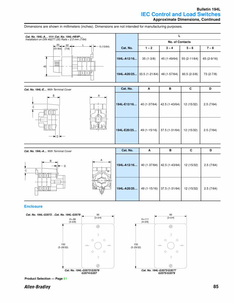
Bulletin 194L
IEC Control and Load Switches
85
Approximate Dimensions, Continued
Dimensions are shown in millimeters (inches). Dimensions are not intended for manufacturing purposes.
Enclosure
Cat. No.
L
No. of Contacts
1 – 2 3 – 4 5 – 6 7 – 8
194L-A12/16... 35 (1-3/8) 45 (1-49/64) 55 (2-11/64) 65 (2-9/16)
194L-A20/25... 33.5 (1-21/64) 48 (1-57/64) 60.5 (2-3/8) 73 (2-7/8)
Cat. No. A B C D
194L-E12/16… 40 (1-37/64) 42.5 (1-43/64) 12 (15/32) 2.5 (7/64)
194L-E20/25… 49 (1-15/16) 37.5 (1-31/64) 12 (15/32) 2.5 (7/64)
Cat. No. A B C D
194L-A12/16… 40 (1-37/64) 42.5 (1-43/64) 12 (15/32) 2.5 (7/64)
194L-A20/25… 49 (1-15/16) 37.5 (1-31/64) 12 (15/32) 2.5 (7/64)
20
(51/64)
22
(7/8)5 (13/64)
L
45
Cat. No. 194L-A… With Cat. No. 194L-HE4P-…
Installation on DIN 46277 (35) Rails + 2.5 mm (7/64)
Cat. No. 194L-E… With Terminal Cover
h Terminal Cover B
D
C
A
Cat. No. 194L-A… With Terminal Cover
nal CoverB
D
C
A
Product Selection — Page 61
150(5-29/32)
H= 86(3-3/8)
95(3-3/4)
150(5-29/32)
H=111(4-3/8)
95(3-3/4)
Cat. No. 194L-G3572…Cat. No. 194L-G3579
Cat. No. 194L-G3572/G3576
G3574/G357
Cat. No. 194L-G3573/G3577
G3575/G3579
Bulletin 194C, 194E,194L
IEC Control and Load Switches
86
Notes

Publication 0194-1.0.1 — M arch 1999Supercedes Publication 194-1.0.1 — September 1997 © 1999 Rockwell International Corporation. All rights reserved. Printed in USA.