flexible, reliable, low cost conveyors engineered for high ... · quality conveyors since 1948...
TRANSCRIPT

Quality Conveyors Since 1948
American Made and American Engineered
Flexible, reliable, low cost conveyors engineered for highspeed and highly automated assembly lines, automationcells and packaging lines.

AS-1The AS-1 single T-slot automationconveyor is designed for generaluse automation applications withsimple straight forward accessorymounting applications.
AS-2The heavier duty AS-2 double T-slot automation conveyor isdesigned for heavier load, higherspeed applications with morecomplex, multifaceted accessorymounting requirements.
Large crowned face pulleys can be tracked easierand carry heavier loads at faster speeds thansmaller diameter pulleys.
Accessories can be easily mounted andmoved anywhere along the conveyor.
Single point belt tensioning systemreduces downtime and maintenance costs.
The largest and longest lastingautomation bearings in the industry.
The combination of both steel and aluminum keepsprices low and provides durability.
1
Flexible, Reliable, Low Cost conveyors engineered for high speed and highly automated assemblylines, automation cells and packaging lines.
Why do we need an Automation Series of conveyors? The increased demand on U.S. manufacturers to reduce costs andimprove productivity has pushed them to automate their production facilities. This Automation transition has resulted ina higher demand for flexible, reliable and lower cost machinery, including conveyors.
New London’s Automation Series (AS) is available in two styles – The AS-1 and the AS-2:
Unique Features of These Units Include:

The Automation Series of Conveyors Story . . . . . . . . . . . . . . . . . . . . . . . . . . . . . . . . . . . . . . . . . . . . . . . . . . . . 1The Automation Series of Conveyors Specifications . . . . . . . . . . . . . . . . . . . . . . . . . . . . . . . . . . . . . . . . . . . . . 2Design and Construction Features. . . . . . . . . . . . . . . . . . . . . . . . . . . . . . . . . . . . . . . . . . . . . . . . . . . . . . . . 3 & 4Slider Beds . . . . . . . . . . . . . . . . . . . . . . . . . . . . . . . . . . . . . . . . . . . . . . . . . . . . . . . . . . . . . . . . . . . . . . . . . 5 & 6Cleated Belts . . . . . . . . . . . . . . . . . . . . . . . . . . . . . . . . . . . . . . . . . . . . . . . . . . . . . . . . . . . . . . . . . . . . . . . . 7 & 8Plastic Belts. . . . . . . . . . . . . . . . . . . . . . . . . . . . . . . . . . . . . . . . . . . . . . . . . . . . . . . . . . . . . . . . . . . . . . . . 9 & 10Plastic Belts (Curved) . . . . . . . . . . . . . . . . . . . . . . . . . . . . . . . . . . . . . . . . . . . . . . . . . . . . . . . . . . . . . . . 11 & 12Drive Locations . . . . . . . . . . . . . . . . . . . . . . . . . . . . . . . . . . . . . . . . . . . . . . . . . . . . . . . . . . . . . . . . . . 13, 14, 15Motor and Speed Charts . . . . . . . . . . . . . . . . . . . . . . . . . . . . . . . . . . . . . . . . . . . . . . . . . . . . . . . . . . . 16, 17, 18Siderails and other options . . . . . . . . . . . . . . . . . . . . . . . . . . . . . . . . . . . . . . . . . . . . . . . . . . . . . . . . . . . 19 & 20Supports . . . . . . . . . . . . . . . . . . . . . . . . . . . . . . . . . . . . . . . . . . . . . . . . . . . . . . . . . . . . . . . . . . . . . . . . . . . . . 21Common Fabric Belting Options . . . . . . . . . . . . . . . . . . . . . . . . . . . . . . . . . . . . . . . . . . . . . . . . . . . . . . . . . . . 22Quick Start – Motor Controls and Accessories . . . . . . . . . . . . . . . . . . . . . . . . . . . . . . . . . . . . . . . . . . 23, 24, 25Photo Gallery . . . . . . . . . . . . . . . . . . . . . . . . . . . . . . . . . . . . . . . . . . . . . . . . . . . . . . . . . . . . . . . . . . . . . . . . . . 26Features and Benefits . . . . . . . . . . . . . . . . . . . . . . . . . . . . . . . . . . . . . . . . . . . . . . . . . . . . . . . . . . . . . . . 27 & 28
TYPE SLIDER BEDS CLEATED BELTS PLASTIC BELTS – STRAIGHT PLASTIC BELTS – RADIUS CURVED (SB) (CL) (PB) (PBR)
MODEL AS-1 AS-2 AS-1 AS-2 AS-1 AS-2 AS-1 AS-2
Applications Short run, Long run, Lighter load Heavier load Short run, Long run, Short run, Long run,light loads, heavier load, inclines and inclines and light load heavier load light load heavier loadtight space fast speed part spacing part spacing plastic belt plastic belt plastic belt plastic beltapplications applications applications applications applications applications applications applications
Belt Widths 2” – 30” 2” – 36” 2” – 30” 2” – 36” 2” – 30” 2” – 36” 4” – 30” 4” – 36”
End Drive Lengths 3’ – 20’ 3’ – 20’ 3’ – 20’ 3’ – 20’ 3’ – 50’ 3’ – 50’ 3’ – 20’ 3’ – 40’
Center Drive Lengths 3’ – 40’ 3’ – 40’ NA NA 3’ – 50’ 3’ – 50’ 3.5’ – 50’ 3.5’ – 50’
Maximum Live Load 700# 1100# 700# 1100# 700# 1300# 200# 200#
Maximum Speed 275 fpm 365 fpm 275 fpm 365 fpm 285 fpm 365 fpm 230 fpm 230 fpm
Frame Depth (12 Ga) 3” 4” 3” 4” 3” 4” 3” 4”
Frame Width BW + 1” BW + 1” BW + 3” BW + 3” BW + 3” BW + 3” BW + 4” BW + 4”
Drive Pulley 3” dia. 4” dia. 3” dia. 4” dia. 19 Tooth x 24 Tooth x 10 Tooth x 12 Tooth x”CFRL* Pulley CFRL* Pulley CFRL* Pulley CFRL* Pulley 3.1” Pitch 3.9” Pitch 3.3” Pitch 3.9” Pitch
Dia. x 1” bore Dia. x 1” bore Dia. x 1” bore Dia. x 1” bore
Drive Shaft Dia. 3/4” 1” 3/4” 1” 3/4” 1” 3/4” 1”
Infeed Pulley 2-1/2” dia. CF* 2-1/2” dia. CF* 2-1/2” dia. CF* 2-1/2” dia. CF* 2-1/2” dia. FF* 2-1/2” dia. FF* 2-1/2” dia. FF* 2-1/2” dia. FF*
Infeed Shaft Dia. 3/4” 3/4” 3/4” 3/4’ 3/4” 3/4” 3/4” 3/4”
Drive Bearing 3/4” bore x 1” bore x 3/4” bore x 1” bore x 3/4” bore x 1” bore x 3/4” bore x 1” bore x(2 bolt flanged) 1.65” OD 1.85” OD 1.65” OD 1.85” OD 1.65” OD 1.85” OD 1.65” OD 1.85” OD
(42MM) (47MM) (42MM) (47MM) (42MM) (47MM) (42MM) (47MM)
Infeed Bearing 3/4” bore x 1” bore x 3/4” bore x 1” bore x 3/4” bore x 1” bore x 3/4” bore x 1” bore x1.65” OD 1.85” OD 1.65” OD 1.85” OD 1.65” OD 1.85” OD 1.65” OD 1.85” OD
Return Rollers 1-5/16” dia. x 2” dia. x 7/16” NA NA 1-5/16” dia. x 2 dia. x 7/16” 1-5/16” dia x 2” dia x 7/16”1/2” shaft rollers shaft rollers 1/2” shaft rollers shaft rollers 1/2” shaft rollers shafat rollers
T-Slots 1” W x 1/4” slot 1” W x 1/4” slot 1” W x 1/4” slot 1” W x 1/4” slot 1” W x 1/4” slot 1” W x 1/4” slot 1”W x 1/4” slot 1” W x 1/4” shot(1) Per side (2) Per side (1) Per side (2) Per side (1) Per side (2) Per side (1) Per side (2) Per side
Belt Pitch NA NA NA NA 1/2” 1/2” 1” 1”
*(CFRL – Crown Faced Rubber Lagged) (CF – Crown Faced( (FF – Flat Faced)For applications with specifications other than specified – contact NLE.
Automation Series Specification Chart
2
Index

Size of New London drive bearing1.85”OD (47mm)
3
CAD 3D models available.
American madeand AmericanEngineered
Designed for shorter run, lighterload, tight space applications.
21/2” diametercrown faced infeed pulley.
3” diameter CFRL*drive pulley
Speeds up to 275 FPM.
Live loads up to 700#.
Single T-slot.
3” deep steel frame made tosurvive the extreme tests of amanufacturing environment.
Single point rack and piniontensioning system reducesdowntime and the expense formaintenance to tension theconveyor belt.
Design and Construction Features
3/4” bore x 1.65 ODdrive bearings(see insert below)
Belt widthsup to 30”
T-Slots are100% accessible.
Adjustable 12 gaugesteel supports.
Compare our prices to aluminumframe competitors – steel ischeaper than aluminum.
– The Lowest PricedAutomation Conveyors in the industry.
– 100% accessible T-Slots.
– Replacement parts areavailable with same day ornext day shipment.
– T-Slots are compatible withother modular framingcompanies such as Frame-World or 80/20®.
*CFRL – Crown Faced Rubber Lagged.
AS-1See pages 27 & 28 for additional features and benefits.
Drive Bearings

Live loads up to 1300#.
Double T-slot for additionalaccessory mounting for itemslike air and electrical lines.
4” deep steel frame made tosurvive the extreme tests of amanufacturing environment.
American madeand AmericanEngineered
Single point rack and piniontensioning system reducesdowntime and the expensesfor maintenance to tensionthe conveyor belt.
11/2" x 11/2" structuralaluminum supports(optional).
Size of typical competitor’s drive bearing
1.57”OD (40mm)
4
CAD 3D models available.
Speeds up to 365 FPM
21/2” diametercrown faced infeed pulley.
4” diameter CFRL*drive pulley
Flexible – Reliable Low Cost Conveyors
Belt widthsup to 36”
T-Slots are100% accessible.
– The Lowest PricedAutomation Conveyors in the industry.
– 100% accessible T-Slots.
– Replacement parts areavailable with same day ornext day shipment.
– T-Slots are compatible withother modular framingcompanies such as Frame-World or 80/20®.
*CFRL – Crown Faced Rubber Lagged.
AS-2See pages 27 & 28 for additional features and benefits.
1” bore x 1.85 ODdrive bearings(see insert below)
Compare our AS series bearings and pulley configurationswith our competitors. These are the most flexible, reliableand lowest priced automation conveyors on the market.

BELT WIDTHS 4” 6” 8” 10” 12” 14” 16” 18” 24” 30”3 FT Lengths 83/103 92/112 101/121 110/130 119/139 128/148 137/157 146/166 173/193 200/230
10 FT Lengths 130/152 146/178 162/186 177/203 193/220 210/237 225/255 240/273 288/324 336/375 20 FT Lengths 196/220 222/250 248/280 272/307 298/336 325/365 350/395 375/425 452/510 530/596 (Weights are listed with end drives first/followed by center drive weights.)
Shipping Weights – lbs.
BELT WIDTHS 4” 6” 8” 10” 12” 14” 16” 18” 24” 30”Estimated Skid Width 24” 24” 24” 24” 26” 28” 30” 32” 38” 44”
Skid Widths – Inches
Conveyors less than 16’ long The skid length is conveyor length + 1’. Conveyors greater than 16’ long The skid length is 17’. Long lengths are shipped in 16’ long sections knocked down and stacked on one another. These weights and dimensions are to calculate freight estimates only. Final dimensions and weights may vary. Weights include standard drive only. Weights for items like supports, belts, crating and other options are not included.
Skid Lengths
5
Slider Beds AS-1 SB
End Drive
Center Drive

BELT WIDTHS 4” 6” 8” 10” 12” 14” 16” 18” 24” 30”3 FT Lengths 85/108 98/118 108/128 118/238 128/138 138/158 148/168 158/178 188/208 218/248
10 FT Lengths 142/154 159/191 176/200 192/218 209/232 227/254 243/273 259/292 310/344 361/400 20 FT Lengths 216/242 245/273 272/304 297/322 324/372 352302 389/423 404/454 484/542 565/631 (Weights are listed with end drives first/followed by center drive weights.)
Shipping Weights – lbs.
BELT WIDTHS 4” 6” 8” 10” 12” 14” 16” 18” 24” 30”Estimated Skid Width 24” 24” 24” 24” 26” 28” 30” 32” 38” 44”
Skid Widths – Inches
Conveyors less than 16’ long The skid length is conveyor length + 1’. Conveyors greater than 16’ long The skid length is 17’. Long lengths are shipped in 16’ long sections knocked down and stacked on one another. These weights and dimensions are to calculate freight estimates only. Final dimensions and weights may vary. Weights include standard drive only. Weights for items like supports, belts, crating and other options are not included.
Skid Lengths
6
Slider Beds AS-2 SB
End Drive
Center Drive

BELT WIDTHS 4” 6” 8” 10” 12” 14” 16” 22” 30”3 FT Lengths 68 76 86 95 103 112 11 148 170
10 FT Lengths 121 137 152 168 185 200 215 263 325 20 FT Lengths 197 223 247 273 300 325 350 427 525
Shipping Weights – lbs.
BELT WIDTHS 4” 6” 8” 10” 12” 14” 16” 22” 30”Estimated Skid Width 24” 24” 24” 26” 28” 30” 32” 38” 46”
Skid Widths – Inches
Conveyors less than 16’ long The skid length is conveyor length + 1’. Conveyors greater than 16’ long The skid length is 17’. Longer lengths are shipped in 16’ long sections knocked down and stacked on one another. These weights and dimensions are to calculate freight estimates only. Final dimensions and weights may vary. Weights include standard drive only. Weights for items like supports, belts, crating and other options are not included.
Skid Lengths
7
Cleated Belts AS-1 CL

BELT WIDTHS 4” 6” 8” 10” 12” 14” 16” 22” 30” 36”3 FT Lengths 72 81 90 101 110 120 129 158 193 228
10 FT Lengths 132 149 165 181 199 215 230 280 345 410 20 FT Lengths 218 245 270 296 324 350 375 454 555 656
Shipping Weights – lbs.
BELT WIDTHS 4” 6” 8” 10” 12” 14” 16” 22” 30” 36”Estimated Skid Width 24” 24” 24” 26” 28” 30” 32” 38” 46” 52”
Skid Widths – Inches
Conveyors less than 16’ long The skid length is conveyor length + 1’. Conveyors greater than 16’ long The skid length is 17’. Long lengths are shipped in 16’ long sections knocked down and stacked on one another. These weights and dimensions are to calculate freight estimates only. Final dimensions and weights may vary. Weights include standard drive only. Weights for items like supports, belts, crating and other options are not included.
Skid Lengths
8
Cleated Belts AS-2 CL

BELT WIDTHS 2” 4” 6” 8” 10” 12” 14” 16” 22” 30”3 FT Lengths 53/73 62/81 71/91 80/100 89/109 98/118 107/127 116/136 143/163 180/200
10 FT Lengths 100/122 116/148 132/156 147/177 163/190 180/207 195/225 210/243 258/294 325/362 20 FT Lengths 166/190 192/220 218/250 242/277 268/306 295/335 320/365 345/395 422/480 525/595 (Weights are listed with end drives first/followed by center drive weights.)
Shipping Weights – lbs.
BELT WIDTHS 2” 4” 6” 8” 10” 12” 14” 16” 22” 30”Estimated Skid Width 24” 24” 24” 24” 26” 28” 30” 32” 38” 46”
Skid Widths – Inches
Conveyors less than 16’ long The skid length is conveyor length + 1’. Conveyors greater than 16’ long The skid length is 17’. Longer lengths are shipped in 16’ long sections knocked down and stacked on one another. These weights and dimensions are to calculate freight estimates only. Final dimensions and weights may vary. Weights include standard drive only. Weights for items like supports, belts, crating and other options are not included.
Skid Lengths
9
– Made of food approved materials– Available for temperature ranges of
(–40 to 200) degrees F.– Cleats (flights), lane dividers and
sideguards are available.1/2” Pitch Flat Top Belt
Standard Plastic Belt Options
1/2” Pitch Flush Grid Belt
Plastic Belts AS-1 PB
End Drive
Center Drive

BELT WIDTHS 2” 4” 6” 8” 10” 12” 14” 16” 22” 30”3 FT Lengths 57/77 66/85 76/96 86/106 95/115 105/123 115/135 124/144 153/173 203/213
10 FT Lengths 111/133 127/159 144/168 160/190 176/203 194/221 210/240 225/258 275/301 345/382 20 FT Lengths 187/211 213/241 240/272 235/300 291/329 319/359 345/390 370/420 459/507 555/625 (Weights are listed with end drives first/followed by center drive weights.)
Shipping Weights – lbs.
BELT WIDTHS 2” 4” 6” 8” 10” 12” 14” 16” 22” 30”Estimated Skid Width 24” 24” 24” 24” 26” 28” 30” 32” 38” 46”
Skid Widths – Inches
Conveyors less than 16’ long The skid length is conveyor length + 1’. Conveyors greater than 16’ long The skid length is 17’. Long lengths are shipped in 16’ long sections knocked down and stacked on one another. These weights and dimensions are to calculate freight estimates only. Final dimensions and weights may vary. Weights include standard drive only. Weights for items like supports, belts, crating and other options are not included.
Skid Lengths
10
– Belts are made of food approved materials– Available for temperature ranges of
(–40 to 200) degrees F.– Cleats (flights), lane dividers and
sideguards are available. (See page 12)1/2” Pitch Flat Top Belt
Standard Plastic Belt Options
1/2” Pitch Flush Grid Belt
This AS-2 PB Model wasproduced with AutocadInventor 3D Software.(Belt not shown)
Plastic Belts AS-2 PB
End Drive
Center Drive

Shipping Weights – lbs.
BELT WIDTHS 4” 6” 8” 10” 12” 14” 16” 18” 24” 30”Estimated Skid Width 24” 24” 25” 27” 29” 31” 33” 35” 41” 47”
Skid Widths – Inches
Conveyors less than 16’ long The skid length is conveyor length + 1’. Conveyors greater than 16’ long The skid length is 17’. Longer lengths are shipped in 16’ long sections knocked down and stacked on one another. These weights and dimensions are to calculate freight estimates only. Final dimensions and weights may vary. Weights include standard drive only. Weights for items like supports, belts, crating and other options are not included.
Skid Lengths
BELT WIDTHS 4” 6” 8” 10” 12” 14” 16” 18” 24” 30”5 FT Lengths 127/152 165/198 190/226 213/255 237/283 261/311 285/340 285/340 358/425 430/510
10 FT Lengths 162/188 208/242 237/277 265/307 292/339 320/371 348/405 348/405 433/500 517/597 20 FT Lengths 232/258 293/330 330/370 365/410 401/450 437/490 475/530 475/530 581/650 690/770 (Weights are listed with end drives first/followed by center drive weights.)
11
AS-1 PBRRadius Curved Plastic Belts
End Drive Center Drive

Shipping Weights – lbs.
BELT WIDTHS 4” 8” 10” 12” 14” 16” 18” 24” 30” 36”Estimated Skid Width 24” 25” 27” 29” 31” 33” 35” 41” 47” 53”
Skid Widths – Inches
Conveyors less than 16’ long The skid length is conveyor length + 1’. Conveyors greater than 16’ long The skid length is 17’. Lengths greater than 16’ will be shipped knocked down and stacked on one another. These weights and dimensions are to calculate freight estimates only. Final dimensions and weights may vary. Weights include standard drive only. Weights for items like supports, belts, crating and other options are not included.
Skid Lengths
BELT WIDTHS 4” 8” 10” 12” 14” 16” 18” 24” 30” 36”5 FT Lengths 127/152 165/198 190/226 213/255 237/283 261/311 285/340 358/425 430/510 502/595
10 FT Lengths 162/188 208/242 237/277 265/307 292/339 320/371 348/405 433/500 517/597 601/694 20 FT Lengths 232/258 293/330 330/370 365/410 410/450 437/490 475/530 581/650 690/770 799/890 (Weights are listed with end drives first/followed by center drive weights.)
12
– Excellent for cooling anddraining applications
– Food approved materials
– Available for temperatureranges of ( –40 to 200) degrees F
– Cleats (flights), lanedividers and sideguards are available.
1” Pitch Radius Curve Belt
Plastic Belt Options Radius Curves
Standard Radius Curve Belt
Sideguards & Lane Dividers
Flights (Cleats)MiddleFlight
EdgeFlight
Sideguards
AS-2 PBRRadius Curved Plastic Belts
End Drive Center Drive

1700 Division Street • New London, WI 54961800-437-1994 • 920-982-4030 • fax: 920-982-6800 • www.nleco.com
Quality Conveyors Since 1948
Center Drive • Bottom Mount • Inline • Under BeltDRIVE #1
Center Drive • Bottom Mount • Right Angle • Discharge FacingDRIVE #17
Center Drive • Bottom Mount • Right Angle • Infeed FacingDRIVE #18
13
Center Drive Locations

End Drive • Bottom Mount • Inline • Under BeltDRIVE #7
End Drive • Bottom Mount • Right Angle • Infeed FacingDRIVE #8
End Drive • Top Mount • Inline • Over BeltDRIVE #9
End Drive • Top Mount • Right Angle • Infeed FacingDRIVE #10
End Drive • Top Mount • Right Angle • Discharge FacingDRIVE #12
14
End Drive Locations

1700 Division Street • New London, WI 54961800-437-1994 • 920-982-4030 • fax: 920-982-6800 • www.nleco.com
Quality Conveyors Since 1948
End Drive • Shaft Mount • Right Angle • Discharge FacingDRIVE #14
End Drive • Shaft Mount • Right Angle • Infeed FacingDRIVE #15
End Drive • Side Mount • Right Angle • Infeed FacingDRIVE #26
End Drive • Side Mount • Inline • Side FacingDRIVE #29
15
End Drive Locations

Shaft Mounted Motors
Standard Speed Options & DimensionsDrive #’s 14 & 15
GEARMOTOR AS-1 AS-2 DIMENSIONS (INCHES) MOTOR OR MAX. MAX. WT. HP REDUCER RATIO FPM *LOAD* FPM *LOAD* A1 A2 B1 # RPM TORQUE
.33 80:1 REDUCER 17 550 22 625 13.75 5.16 8.19 55 22 593 .5 GEARMOTOR 22 550 30 630 12.95 5.07 6.84 45 29 600 .5 50:1 REDUCER 27 550 37 675 14.37 5.16 8.19 56 35 640 .5 40:1 REDUCER 35 550 45 515 14 4.85 7.94 56 43 490 .75 40:1 REDUCER 35 550 45 840 14.87 5.16 8.19 59 43 800 1 GEARMOTOR 45 550 60 790 15.14 5.55 7.67 55 58 750 .5 20:1 REDUCER 67 395 90 315 14 4.85 7.94 56 86 300 .75 20:1 REDUCER 67 550 90 475 15.24 4.85 7.94 59 86 450 .5 GEARMOTOR 70 325 92 265 12.95 5.07 6.84 45 88 250 1 GEARMOTOR 70 550 92 580 15.12 5.55 7.67 55 88 550 1 10:1 REDUCER 135 210 180 170 14 4.85 7.94 56 173 162 .5 GEARMOTOR 135 195 180 160 12.95 5.07 6.84 45 173 150 1 10:1 REDUCER 135 425 180 340 15.28 5.35 8.48 60 173 324 1.5 10:1 REDUCER 135 550 180 510 16.15 5.35 8.49 67 173 486 .5 5:1 REDUCER 270 110 362 85 14 4.85 7.94 56 345 83 .75 5:1 REDUCER 270 165 362 130 15.24 4.85 7.94 59 345 124 1.5 5:1 REDUCER 270 325 362 260 16.15 5.35 8.49 67 345 249
.33 80:1 REDUCER 17 550 22 625 13.75 5.16 8.19 55 22 593 .5 60:1 REDUCER 22 550 30 745 13.75 5.16 8.19 56 29 709 .5 208-230 GEARMOTOR 22 550 30 630 13.23 5.07 6.84 40 29 600 .5 50:1 REDUCER 27 550 37 675 13.75 5.16 8.19 56 35 640 .5 40:1 REDUCER 35 550 45 515 13.38 4.85 7.94 56 43 490 .75 40:1 REDUCER 35 550 45 840 13.75 5.16 8.19 59 43 800 1 208-230 GEARMOTOR 45 550 60 790 13.84 5.07 7.1 45 58 750 .5 20:1 REDUCER 67 395 90 315 13.38 4.85 7.94 56 86 300 1 20:1 REDUCER 67 550 90 640 14.4 5.16 8.19 60 86 608 1 208-230 GEARMOTOR 70 550 92 580 13.84 5.07 7.1 45 88 550 .5 10:1 REDUCER 135 210 180 170 13.38 4.85 7.94 56 173 162 .75 10:1 REDUCER 135 320 180 255 13.38 4.85 7.94 59 173 243 1 208-230 GEARMOTOR 135 395 180 315 13.84 5.07 7.1 45 173 300 1.5 10:1 REDUCER 135 550 180 510 14.25 5.35 8.48 67 173 486 2 10:1 REDUCER 135 550 180 680 15.25 5.35 8.48 77 173 648 .5 5:1 REDUCER 270 110 362 85 13.38 4.85 7.94 56 345 83 .75 5:1 REDUCER 270 165 362 130 13.38 4.85 7.94 59 345 124 1.5 5:1 REDUCER 270 325 362 260 14.25 5.35 8.48 67 345 249 2 5:1 REDUCER 270 435 362 350 15.25 5.35 8.48 77 345 332
.125 GEARMOTOR 5 500 7 400 9.24 2.23 3.34 14 6.2 380 .125 GEARMOTOR 7 470 10 375 9.24 2.23 3.34 14 9.1 358 .33 80:1 REDUCER 17 550 22 625 14.65 7.14 5.91 60 22 593 .125 GEARMOTOR 22 200 30 160 9.24 2.23 3.34 14 29 151 .33 60:1 REDUCER 22 550 30 485 14.28 6.83 5.66 60 29 460 .5 60:1 REDUCER 22 550 30 745 15.59 7.14 5.91 65 29 709 .5 50:1 REDUCER 27 550 37 675 15.59 7.14 5.91 65 35 640 .5 40:1 REDUCER 35 550 45 515 15.22 6.83 5.66 65 43 490 .75 40:1 REDUCER 35 550 45 840 16.99 6.06 6.1 71 43 800 .5 20:1 REDUCER 67 395 90 315 15.22 6.83 5.66 65 86 300 1 20:1 REDUCER 67 550 90 640 17.86 6.06 6.1 77 86 608 .125 GEARMOTOR 135 40 180 35 8.04 3.31 3.27 10 173 31 .5 10:1 REDUCER 135 210 180 170 15.22 6.83 5.66 65 173 162 1 10:1 REDUCER 135 425 180 340 17.49 5.75 5.85 77 173 324 .5 5:1 REDUCER 270 110 362 85 15.22 6.83 5.66 65 345 83 1 5:1 REDUCER 270 215 362 175 17.49 5.75 5.85 77 345 166
3 PHASE 230/460/3/60
1 PHASE 115/230/1/60
90 VOLT DC
16

Right Angle
Standard Speed Options & DimensionsDrive #’s 8, 10, 12, 17, 18, 26
GEARMOTOR AS-1 AS-2 DIMENSIONS (INCHES) MOTOR OR MAX. MAX. WT. HP REDUCER RATIO FPM *LOAD* FPM *LOAD* A1 A2 B1 # RPM TORQUE
.111 GEARMOTOR 17 135 25 105 8.537 535 3.84 12 23 102 .083 GEARMOTOR 22 100 30 80 7.29 5.32 4.39 10 29 75 .5 60:10 REDUCER 22 550 30 745 14.37 7.47 9.53 53 29 709 .125 GEARMOTOR 27 165 37 130 9.54 5.85 7 16 35 125 .5 50:1 REDUCER 27 550 37 675 14.4 7.47 9.53 53 35 640 .5 40:1 REDUCER 35 550 45 515 14 6.91 9.94 53 43 490 .75 40:1 REDUCER 35 550 45 840 14.9 9.53 9.53 56 43 800 .167 GEARMOTOR 35 170 45 135 8.76 5.49 5.29 15 44 130 .125 GEARMOTOR 40 130 52 105 9.54 5.85 7 16 50 100 .167 GEARMOTOR 65 100 85 80 8.76 5.49 5.29 15 82 75 .5 20:1 REDUCER 67 395 90 315 14 6.91 9.94 53 86 300 1 20:1 REDUCER 67 550 90 630 15.65 9.92 10.1 57 86 600 .167 GEARMOTOR 135 55 180 45 8.76 5.49 5.29 15 173 43 .5 10:1 REDUCER 135 210 180 170 14 6.91 9.94 53 173 162 .75 10:1 REDUCER 135 220 180 255 14.5 8.97 9.94 56 173 243 1.5 10:1 REDUCER 135 550 180 510 16.15 9.36 10.3 64 173 486 .5 5:1 REDUCER 270 110 362 85 14 6.91 9.94 53 345 83 .75 5:1 REDUCER 270 165 362 130 14.5 8.97 9.94 56 345 125 1.5 5:1 REDUCER 270 325 362 260 16.15 9.36 10.3 64 345 249 3 PHASE 230/460/3/60 .33 80:1 REDUCER 17 550 22 625 13.75 7.47 9.53 52 22 593 .375 GEARMOTOR 17 160 25 125 8.86 5.72 4.21 18 23 121 .33 60:1 REDUCER 22 550 30 485 13.38 6.91 9.94 52 29 460 .5 60:1 REDUCER 22 550 30 745 13.75 7.47 9.53 53 29 709 .167 GEARMOTOR 27 165 37 130 8.26 5.74 6.98 16 35 125 .33 50:1 REDUCER 27 535 37 430 13.38 6.91 9.94 52 35 407 .5 40:1 REDUCER 27 550 37 675 13.75 7.47 9.53 53 35 640 .33 40:1 REDUCER 35 450 45 360 13.38 6.91 9.94 52 43 342 .5 40:1 REDUCER 35 550 45 515 13.38 6.91 9.94 53 43 490 .75 40:1 REDUCER 35 550 45 840 13.75 7.47 9.53 56 43 800 .4 GEARMOTOR 35 365 45 295 11.88 6.23 7.16 35 44 280 .4 GEARMOTOR 70 260 92 210 11.88 6.23 5.66 35 88 200 .375 GEARMOTOR 135 130 180 105 8.86 5.72 4.21 18 173 101 .5 10:1 REDUCER 135 210 180 170 13.38 6.91 9.94 53 173 162 .75 10:1 REDUCER 135 320 180 255 13.38 6.91 9.94 56 173 243 1 10:1 REDUCER 135 425 180 340 14.03 6.91 9.93 57 173 324 1.5 10:1 REDUCER 135 550 160 510 14.25 7.41 10.5 64 173 486 2 10:1 REDUCER 135 550 180 680 15.25 7.41 10.5 74 173 648 .33 5:1 REDICER 270 70 362 60 13.38 6.91 9.94 52 345 55 .375 GEARMOTOR 270 70 362 55 8.86 5.72 4.21 18 345 54 .5 5:1 REDUCER 270 110 362 85 13.38 6.91 9.94 53 345 83 .75 5:1 REDUCER 270 165 362 130 13.38 6.91 9.94 56 345 124 1 5:1 REDUCER 270 215 362 175 14.03 6.91 9.93 57 345 166 1.5 5:1 REDUCER 270 325 362 260 14.25 7.41 10.5 64 345 249 2 5:1 REDUCER 270 435 362 350 15.25 7.41 10.5 74 345 332 90 Volt DC .33 80:1 REDUCER 17 550 22 625 14.65 9.45 7.59 57 22 593 .125 GEARMOTOR 22 100 30 80 8.64 5.32 4.75 14 29 75 .33 60:1 REDUCER 22 550 30 485 14.28 8.89 7.99 57 29 460 .5 60:1 RECUCER 22 550 30 745 15.59 9.45 7.59 62 29 709 .33 50:1 REDUCER 27 535 37 430 14.28 8.89 7.99 57 35 407 .5 50:1 REDUCER 27 550 37 675 15.59 9.45 7.59 62 35 640 .33 40:1 REDUCER 35 450 45 360 14.28 8.89 7.99 57 43 342 .5 40:1 REDUCER 35 550 45 515 15.22 8.89 7.99 62 43 490 .75 40:1 REDUCER 35 550 45 840 16.99 8.37 7.44 68 43 800 .167 GEARMOTOR 35 175 45 140 9.13 4.96 3.43 10 44 135 .5 GEARMOTOR 45 280 60 225 12.72 8.71 4.18 35 58 215 .25 GEARMOTOR 60 130 80 105 9.14 5.32 7.75 14 76 100
3 PHASE 230/460/3/60
1 PHASE 115/230/1/60
90 VOLT DC
1790 Volt DC (continued on page 18)

InlineStandard Speed Options & Dimensions
Drive #’s 1, 7, 9, 29
GEARMOTOR AS-1 AS-2 DIMENSIONS (INCHES) MOTOR OR MAX. MAX. WT. HP REDUCER RATIO FPM *LOAD* FPM *LOAD* A1 A2 B1 # RPM TORQUE
.33 20:1 REDUCER 67 260 90 205 14.28 8.89 7.99 57 86 197 .5 20:1 REDUCER 67 395 90 315 15.22 8.89 7.99 62 86 300 .75 20:1 REDUCER 67 550 90 475 16.62 7.81 7.65 68 86 450 1 20:1 REDUCER 67 550 90 640 17.86 8.37 7.44 74 86 608 .5 GEARMOTOR 97 190 130 150 12.72 8.71 4.76 35 125 145 .083 GEARMOTOR 135 30 180 25 7.89 4.96 3.43 10 173 22 .33 10:1 REDUCER 135 140 180 110 14.28 8.89 7.99 57 173 107 .5 10:1 REDUCER 135 210 180 170 15.22 8.89 7.99 62 173 162 .75 10:1 REDUCER 135 45 180 35 16.62 7.81 7.65 68 173 33 1 10:1 REDUCER 135 250 180 200 17.49 7.81 7.65 74 173 190 .167 GEARMOTOR 270 30 362 25 9.13 4.96 3.43 10 345 24 .33 5:1 REDUCER 270 70 362 60 14.28 8.89 7.99 57 345 55 .5 5:1 REDUCER 270 110 362 85 15.22 8.89 7.99 62 345 83 .75 5:1 REDUCER 270 165 362 130 16.62 7.81 7.65 68 345 124 1 5:1 REDUCER 270 215 362 175 17.49 7.81 7.65 74 345 166
90 VOLT DC (continued)
18
New London Engineering Rack & Pinion Belt Tension and Belt Take Up Instructions
1. Loosen the 3/16” and 1/4” head boltson the conveyor right side.
2. Loosen the black 3/16” head bolt on the left side.
3. Loosen or tighten the belt via the silver 1/4” head bolt on the left sidethen re-tighten all bolts.
GEARMOTOR AS-1 AS-2 DIMENSIONS (INCHES) MOTOR OR MAX. MAX. WT. HP REDUCER RATIO FPM *LOAD* FPM *LOAD* A1 A2 B1 # RPM TORQUE
.125 GEARMOTOR 17 355 25 285 6.280 4.87 10.8 18 23 270 .167 GEARMOTOR 22 355 30 285 4.64 4.64 9.13 15 29 270 .5 GEARMOTOR 45 550 60 510 9.19 6.28 12.9 25 58 484 .5 GEARMOTOR 70 425 92 345 9.19 6.28 12.9 25 88 326 .5 GEARMOTOR 135 215 180 170 9.19 6.28 12.9 25 173 164 .33 GEARMOTOR 270 70 362 60 7.05 6.35 12.9 15 345 55
.167 GEARMOTOR 7 445 10 360 4.67 4.67 8.11 11 9.4 341 .167 GEARMOTOR 22 355 30 285 4.67 4.67 8.11 12 29 270 .167 GEARMOTOR 45 125 60 100 4.04 4.04 8.35 17 57 96 .33 GEARMOTOR 45 420 60 335 7.05 4.87 11.9 17 58 320 .33 GEARMOTOR 70 285 92 230 7.05 4.87 11.9 17 88 218 .5 GEARMOTOR 135 215 180 170 7.05 4.87 11.9 17 173 164 .375 GEARMOTOR 270 75 362 60 4.54 4.64 9.57 24 345 58
.125 GEARMOTOR 22 295 30 240 4.64 4.64 9.06 11 29 226 .125 GEARMOTOR 35 230 45 185 4.10 4.17 8.37 12 44 174 .25 GEARMOTOR 45 290 60 230 4.87 4.87 10.3 17 58 220 .25 GEARMOTOR 70 205 92 165 4.87 4.87 10.3 17 88 155 .25 GEARMOTOR 135 90 180 75 4.87 4.87 9.42 17 173 70 .25 GEARMOTOR 197 65 262 55 4.87 4.87 9.42 17 250 50 .33 GEARMOTOR 270 70 362 60 4.87 6.42 12.8 24 345 55
3 PHASE 230/460/3/60
1 PHASE 115/230/1/60
90 VOLT DC
*Maximum load weights are based on a 12” wide x 10’ long, straight running conveyor.
Belt Direction Belt Direction Belt Direction
19
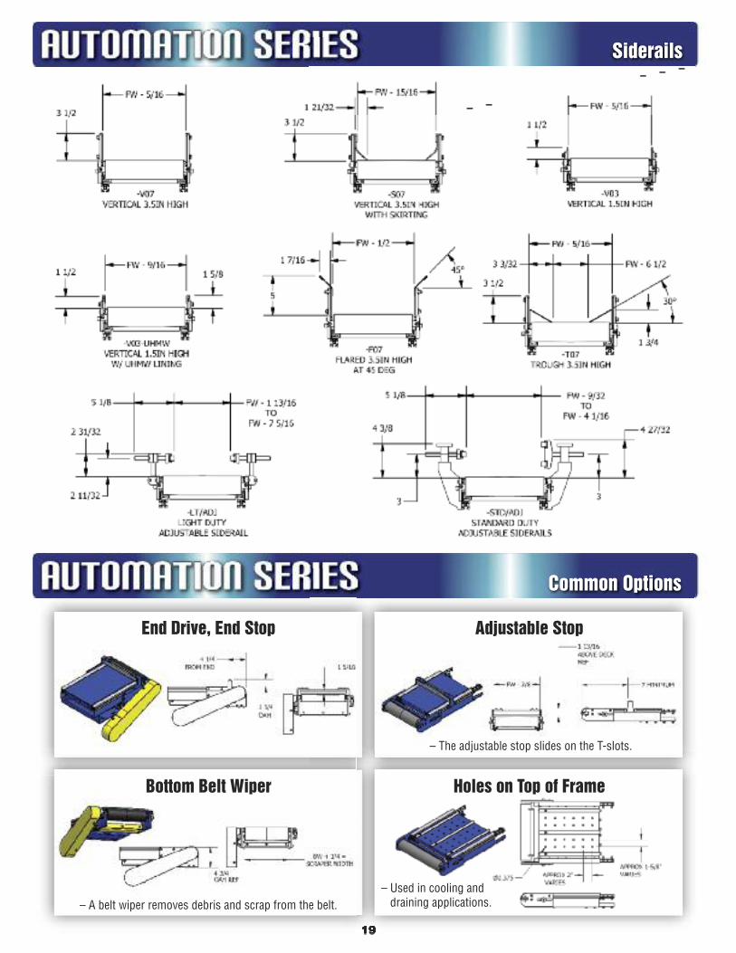
Siderails
Common Options
End Drive, End Stop
Bottom Belt Wiper
Adjustable Stop
Holes on Top of Frame
– The adjustable stop slides on the T-slots.
– A belt wiper removes debris and scrap from the belt.– Used in cooling and
draining applications.

20
– Available in bottom, shaft, side or center mount locations (bottom mount shown).
– Available in all belt styles(rubber, cleated or plastic belts).
Common Drive
– Due to variations in set ups, pinchpoint guarding is the responsibility of the end user.
– Minimum part thickness is 1/4”.
– Maximum suggested product weight is 20 lbs. @ 60 FPM.
– Package includes adjustable turnguide, guide wheel and transfer plate.
– This option allows you to create yourown lanes, plows, merges or transfers.
– The number of guides must bespecified per the application.
– Guides are UHMW lined.
– Maximum product heights must benoted to insure product will not hit thetop mounting bracket.
– Package includes UHMW lined laneguide (# of guides per application),mounting brackets and adjusting knobs.
Adjustable Lane Guiding
– Mounts off the end of the infeed section.
– Includes both a horizontal andvertical adjustment to minimizegap and optimize product transfer.
Pulley Transfer Plate
Common Options
90° Degree Transfer

21
For a larger version of a drawing or to print a copy see our website at WWW.NLECO.COM and click on DRAWINGS
UpperSupport
SmileBracket
LowerSupport
Spreader
STANDARD DUTY SUPPORT LEGS #0A THRU #0K
STANDARD DUTY SUPPORT #A THRU #I
MIN–MAX PART LENGTH # OF PART # RANGE LOWER UPPER SPREADERS 1A 2" – 3" 1-7/8" 1-3/4" 0 1B 3" – 4" 2-7/8" 1-3/4" 0 1C 4" – 5" 3-7/8" 1-3/4" 0 1D 5" – 6" 4-7/8" 1-3/4" 0 1E 6" – 7-1/2" 5-3/4" 0 1F 7" – 8-1/2" 6-3/4" Smile 0 1G 8" – 9-1/2" 7-3/4" Bracket 0 1H 9" – 10-1/2" 8-3/4" Only 0 1I 10" – 11-1/2" 9-3/4" 0 0A 11" – 14" 5-1/2" 9" 1 0B 13-1/2" – 17" 8" 11" 1 0C 16" – 22-1/2" 10-1/2" 14" 1 0D 22" – 31" 12-7/8" 19" 1 0E 30-1/2" – 39-1/2" 12-7/8 28-1/2" 1 0F 39" – 48" 12-7/8 37" 1 0G 47-1/2" – 56-1/2" 12-7/8 45-1/2" 2 0H 56" – 65" 12-7/8 54" 2 0I 64-1/2" – 73-1/2" 12-7/8 62-1/2" 3 0J 73" – 82" 12-7/8 71" 3 0K 81-1/2" – 90-1/2" 12-7/8 79-1/2" 3
Standard Duty Supports – 12 Gauge Unistrut Style
SUPPORT HEIGHTS # SPREADERS
2” – 12” 1 13” – 36” 2 37” – 60” 3
1-1/2” x 1-1/2” Structural Aluminum Supports (Part #SA)1-1/2” x 1-1/2” x SA support heights are made per the application.#SA supports adjustment range is +/–2”.Note: Leveling pads add an additional 3” of adjustment.
Standard support options include knee braces, casters, floor locks,leveling pads and single post style supports.
CONVEYOR # SUPPORTS CONVEYOR # SUPPORTS LENGTH REQUIRED LENGTH REQUIRED 5' – 14' 2 Pair 55' – 64' 7 Pair 15' – 24' 3 Pair 65' – 74' 8 Pair 25' – 34' 4 Pair 75' – 84' 9 Pair 35' – 44' 5 Pair 85' – 94' 10 Pair 45' – 54' 6 Pair 95' – 104' 11 Pair
Number of Supports Required
Post StyleSupportwithLevelingPads
Casters
Floor Locks
SMILEBRACKET
KNEE BRACEBRACKET
KNEEBRACE
UPPERSUPPORT
LOWERSUPPORT
SPREADER
Standard Duty Style Support
(SA) Style Side View
21/2” 31/4” 4”
Supports
Standard Duty Supports
(SA) Style Supports

22
GENERAL PURPOSE COMMON AUTOMATION SERIES FABRIC BELT CHOICES – The first belt listed is the cheapest *2 Ply 70 Black PVC x IMPG (Spec #251) (Temp. Range 20°F to 180°F) (.093” Thick)
This oil and cut resistant PVC cover is the ideal surface for general purpose conveying. The monofilament (multi-plied-2 plies or more) style construction provides strengthand flexibility. This belt runs smooth, flat and quiet because the bottom is impregnated (coated) with a filler material resulting in a soft and level, low noise surface.
*2 Ply 60 Black PVC x Bare Bottom (Spec #60) (Temp. Range 20°F to 180°F) (.078” Thick) Two plies of polyester fabric provide strength for this thin belt commonly used for retail checkout stands. The black PVC cover resists stains, cutting and gouges
from rough use. The Matte cover is easily cleaned and the bare bottom back provides a low friction, low noise surface.
ACCUMULATION Black PVC 100 Friction Surface x Brushed Bottom (Spec #64B) (Temp Range 20°F to 180°F ) (.125” Thick) Proven problem free package handling belt. Friction surfaces on both sides permit belt to move and accumulate products – this is a good low cost accumulation
belt. Belt has good stretch, rip, tear and gouge resistance.
3 Ply Brown Nitrile Friction Surface x Friction Surface (Spec #110) (Temp Range 0°F to 250°F) (.078” Thick) This belt’s tightly woven blend of cotton and polyester fabric combined with Nitrile compounds makes this construction popular for a variety of light to medium
weight accumulations and conveying applications. Good for metal parts and for carrying tapes for packaging machines. Good oil, grease and chemical resistance.
*2 Ply Ultimate 80 Accumulating Belt (Spec #255X) (Temp. Range 10°F to 175°F) (.100” Thick) This belt’s frictionless top surface and unique non-woven construction makes this an excellent economical choice for accumulating everything from boxes to oily,
sharp edge metal stampings.
*2 Ply Urethane Impregnated Bare Top & Bottom Accumulation Belt (Spec #256X) (Temp. Range 5°F to 175°F) (.60” Thick) This belt is considered the “Cadillac” of the accumulation belts. The bare top surface is good for accumulating and the bare bottom surface slides on the slider
bed. This 2-ply urethane impregnated belt is resistant to cuts, abrasions and oils. This is our best choice for those nasty & dirty accumulation applications.
ROUGH TOP *2 Ply Green PVC Rough Top x Bare Back (Spec #250) (Temp. Range 20°F to 160°F) (.210” Thick) This high grip, grease and oil resistant PVC belt ha a nonskid textured surface that enables packages, boxes and other products to be conveyed on both inclines
and declines. This belt runs smooth, flat and quiet due to the special low noise cover and its bare back that provides a low friction, low noise surface.
*2 Ply Black Longitudinal Ribbed Top x Bare Back (Spec #253X) (Temp. Range 15°F to 175°F) (.90” Thick) This belt is designed for high and steep incline applications. The longitudinal raised ribbed surface literally grips and holds the parts being conveyed. This belt will run
smooth, flat and quiet due to the bare back low friction, low noise surface. This belt is especially suited for plastic totes. This s a good belt for steep inclines/declines.
*2 Ply Gray PVC Lattice Top x Bare Back (Spec #254X) (Temp. Range 15°F to 140°F) (.080” Thick) The soft PVC cover combined with the raised lattice style surface grips the parts and prevents roll back of lightweight plastic parts and totes. The belt will run
smooth, flat and quiet due to the bare back low friction, low noise surface. Good plastic parts belt.
URETHANE 2 Ply Green Urethane x IMPG Back (Spec #249) (Temp. Range 20°F to 180°F) (.050” Thick) An economical yet high quality thin urethane belt with excellent cut and gouge resistance. This is an excellent choice for conveying sharp parts where an
abundance of oil is present. This belt runs smooth, flat and quiet because the bottom is impregnated (coated) with a filler material resulting in a soft and level, low noise surface. This smooth top belt is also a good choice for light duty accumulating applications.
*2 Ply Green Heavy Duty Urethane x Bare Back (Spec #255) (Temp. Range 15° to 175°F) (.90” Thick) This heavy-duty urethane belt has an extra thick urethane top cover. (95% thicker – .039” versus the standard .020”). This belt is the preferred choice for conveying
larger, heavier oily parts under tough loading conditions. This belt runs smooth, flat and quiet due to the bare back (non-coated) low friction, low noise surface.
WHITE BELTS *2 Ply White PVC (Spec 224) (Temp. Range 20°F to 180°F) (.078” Thick) Anti-static, FDA and USDA accepted general food conveying belt. This low cost belt is ideal for general transporting any food product and in an all non-marking
applications.
1 Ply White Urethane x IMPG Bottom (Spec #222) (Temp. Range 20°F to 180°F) (.031” Thick) This belt has a smooth non-adhesive white urethane top cover. Excellent choice for cooling tunnels and applications requiring a high release surface. This belt
runs smooth, flat and quiet because the bottom is impregnated (coated) with a filler material resulting in a soft and level, low noise surface.
*2 Ply 70 White Nitrile 3/64 x Friction Surface (Spec #91) (Temp. Range 0°F to 250°F) (.093” Thick) This high strength, great dimensional stability belt is ideal for wide and fast applications. FDA and USDA accepted.
*2 Ply White Urethane x IMPG Bottom (Spec #223) (Temp. Range 20°F to 180°F) (.062” Thick) This belt’s smooth non-adhesive white urethane top cover is ideal for applications where added strength and good release characteristics are required. It runs
smooth, flat and quiet because the bottom is impregnated (coated) resulting in a soft and level, low noise surface. FDA and USDA accepted.
3 Ply Polyester 105 White Butyl (Spec #98) (Temp. Range –65°F to –300°F) (.109” Thick) This belt is designed for extreme temperature variations from –65 degrees to 300 degrees F. Used in heat-sealing machines, shrink tunnels and other high
temperature applications. This belt is also used in cold rooms and freezers where cold temperatures are the norm. FDA an USDA accepted.
3 Ply Polyester 105 White Tyler Wire x Friction Surface (Spec #99) (Temp. Range 0°F to 250°F) (.125’ Thick) This belt’s surface has a slight wire-like impression that produces enough traction for use in moderate incline/decline applications. Often used for handling boxes,
packages and small parts. It is a good non-marking oil and grease resistant belt to use in cold or hot applications. FDA and USDA accepted.

New OptionQuick Disconnect Motors, Controllers and AccessoriesUnits can be pre-wired with a quick connect/disconnect receptacle. Eliminates highvoltage wiring dangers. Provides quick and easy maintenance and accessory mounting.
New OptionAC and DC Drive Packages – The Ultimate “Plug and Play” Motor Control OptionSave time and money by ordering your motor and controller pre-wired. Packages can be hard wired or wired with quickdisconnects. Pre-wired packages include 4’ of cord between the motor and controller & 10’ of power cord – other cord lengthsper customer request.
Manual Motor Starters• Push Button Start / Stop – with overload protection
• Plastic NEMA 12 enclosure
• Full voltage range up to 600 VAC
• Optional quick disconnect receptacle
• Note: unit is not magnetic thus it’s not recommended for use with e-stop circuits.
Magnetic Reversing or Non-Reversing Starters• Built in Start / Stop / Reverse / Manual Reset push buttons
with overload protection
• Compatible for both single and three-phase input
• NEMA 1-metallic lift-off enclosure with knockouts
• NEMA 12 metal enclosure available
DC Variable Speed Controllers (Simple, low cost DC speed control)• NEMA 1 enclosure
• On / Off switch
• Speed potentiometer
• 90V units include 10’ motor cord and plug 180V units include 10’ motor cord with no plug
Save Time & Installation Costs With New London’s “Quick Start”Motor Control Solutions
Manual MotorStarters
Magnetic Reversingor Non-ReversingStarters
DC Variable SpeedControllers
DC Drive Package AC Drive Package
23
(Available with Reverse)

24
AC Variable Speed Controllers – Why use an AC Variable Speed Controller?A “Variable” frequency drive uses an electronic controller to monitor the amount of electrical power being supplied to the motor.It adds more current /power when it’s needed and reduces current/power when it’s not needed.
Single speed drives do not control the amount of power being supplied to the motor. When the power is turned on, the motor startsabruptly at full current, which subjects the motor to high torque and current surges up to 10 times the motor’s full load capacity.
A variable speed frequency drive provides a soft start, gradually ramping up a motor to operating speed. This gradual increase incurrent, lessens mechanical and electronic stress on the motor which reduces maintenance and repair costs and extends motor life.
Consider upgrading to a variable speed controller when:
– the application requires an accurate and continuous speed (when speed control is vital)– smooth acceleration is important (a smooth acceleration prevents damage and jams)– production speeds vary from day to day– the application requires indexing (frequent stops and starts)– belt speeds vary with information supplied from accessories
like photo eyes or stop/start push buttons
AC Variable Speed Controller (Simple, low cost speed control)• Keypad speed control, digital readout and overload protection• Pre-wired motor and power cord packages optional• NEMA 12 enclosure with mounting hardware• Stop/Start /Forward/Reverse• Capable of controlling up to (1) input device (photo eye, E-stop, etc.)
AC Variable Speed Controller with Parameter Programming(Full feature variable speed controller used for simple accessoryinput applications.)
• Pre-wired motor and power cord packages optional• Keypad speed control, digital readout and overload protection• NEMA 12 enclosure with mounting hardware (Nema 4X available)• Stop/Start /Forward/Reverse• Capable of controlling up to (1) input device (photo eye, E-stop, etc.)
AC Variable Speed Controller with Parameter Programmingwith up to 5 Inputs(Full feature variable speed controller used with more complicatedaccessory applications.)
• Units pre-programmed parameters can be easily over-ridden tocustomize the program for your needs.
• Pre-wired motor and power cord packages optional• Internal terminals for hardwired PLC or machine interface• Keypad speed control, digital readout and overload protection• Communication card available• Stop/Start /Forward
The “Super Drive” Programmable AC Variable Speed Controller with up to 5 inputs(This powerful controller is used when your application includesinput and output from multiple locations and devices, ie – indexingapplications, zone accumulations, controlled product throughout andgap control, PLC integration.)
• Many general purpose applications are pre-programmed at the factory
• Pre-wired motor and power cord packages optional• Internal terminals for hardwired PLC or Machine interface• Easy on site programming (instructions included)• 24/7/365 programming help center• LED digital read out display• Communication card available• Full feature VFD control• Operator interface panel• NEMA 12 Enclosure
AC Variable Speed Controller
AC Variable Speed Controllerwith One InputReceptacle
AC Variable SpeedController with up to 5 inputs
The “Super Drive”Progammable ACVariable SpeedController with up to 5 Inputs

25
Emergency Stop(Used in emergency situations to shut off power to the conveyor.)
• Plastic NEMA 12 enclosure
• Optional quick disconnect receptacle and cords
• Illuminated version optional
• Horizontal mounting bracket is standard
Jog Push Button• Push button jog switch
• Plastic NEMA 12 enclosure
• Optional quick disconnect receptacle and cords
• Horizontal or vertical mount
Remote Start / Stop• Push to stop/push to start (requires 2 inputs – One to stop & one to start)
• Plastic NEMA 12 enclosure
• Optional quick disconnect receptacle and cords
• Horizontal or vertical mount)
Extension Cables• 2 meter thru 30 meter lengths
• Quick disconnect extension cables
Photo Eyes• Diffuse, Through Beam,
Retro Reflective styles available
• 24V DC
• Wiring per application
• Mounting brackets made per the application
Proximity SensorsProximity sensors are very inexpensive and easy to use. Typical uses include safety (motion detection), speed control feedback, part detection, product positioning for labeling or filling, batch counting or accumulation applications.
• Available unwired or wired
• 24 V DC
• Mounting brackets made per the application
Photo Eye / Proximity Sensor Bracket Kits• Standard mounting for 18mm barrel
• Mounting brackets made per the application
Note: When buying a motor without a starter, the customer must supply their own on/off switch and motor overload protection to comply with NEC and CE safety directives.
EmergencyStop
Jog Push Button
RemoteStart / Stop
Photo EyesExtension Cables
ProximitySensors
Photo Eye / ProximitySensor Bracket Kits

26
Automation Series Photo Gallery
This is an AS-2 Slider Bed Conveyor with 3” highsmooth structural aluminum siderails and a work table. The work table is made entirely ofFrame-World extrusions and components.
Build your own siderails. These siderails are 1” x 1” rounded extrusions fastened to the T-slot. Note: Right side includes a specialmounting bracket to overlap the belt.
——— You can mount almost anything in the T-Slots with simple hand tools ———
————————— Make your own modifications in the field —————————
Adjustable Photo EyeBracket (up / down and
side to side adjustments)
Jog PushButton
100%Accessible
T-Slots E-Stop
ProximitySensor
RemoteStart / Stop
Optional StructuralAluminum Supports
Photo Eyes
Radius CurveT-Slot Covers
Pre-Wired “Plug and Play”Control Package
All items arefastened usingthese Pivot T-Nuts.

27
FEATURE FLEXIBILITY FEATURES SUMMARY STATEMENT
– The T-slots on the AS-1 and AS-2 are 100% accessible. The supports aremounted on the frames bottom side (not in the T-slot) so there are noobstructions in the T-slots. This means accessories can be easily mountedand moved anywhere on the conveyor.
– Most competitors mount their supports in the T-slots – these large support mounting brackets get in your way and limit your accessorymounting flexibility.
– The AS-1 and AS-2 utilize a combination of both steel and aluminum.
– Steel can be cut and formed to your exact length, width and depthrequirements.
– The aluminum T-slots are purchased in 16’ lengths so they can also beeasily cut to your specifications.
– The automation series includes a rack and pinion belt tensioning system.This fast and accurate, single point belt tensioning system reducesdowntime and maintenance costs.
– Loosening the tension system contracts the infeed section providing themeans for quick and easy belt removal or repair.
– We use name brand components like Baldor Motors and Dodge Bearingson our American Made and American Engineered conveyors.
– Since we use many of the Automation Series components on other NewLondon conveyors, we can rely on this inventory of parts to provide timelyreplacement part delivery.
Our goal is to provide the shortest quote thru delivery lead times in theconveyor industry. If you need it fast, we can help!
– Do you want to build your own CAD model to insert into your drawing? We have a library of AutoCAD 3D Models and 2D drawings available foryou to download quickly and easily.
– The T-slots are fully compatible with the accessories from modular framingcompanies like Frame-World and 80/20®. Our compatible T-slots allow youto make your own additions or revisions easily and cost effectively withoutyour equipment looking patched or run down.
These units are built to survive the extreme tests of the manufacturingenvironment. Use our Specification Chart to compare the AS-1 and AS-2specs to their competitors.– Higher live loads and faster speeds– Deeper steel constructed frames – steel is stronger and more durable than
aluminum.– Larger diameter bearings and shafts
The AS-1 and AS-2 are the onlyautomation conveyors on the marketwith 100% accessibility to the T-slots.
Steel can be formed and bent to fit yourapplications exact requirements.
Aluminum only frames cannot be bentand formed to your exact needs.
The rack and pinion take up system provides a fast, accurate and easy belt tensioning and beltreplacement system.
Since our conveyors are manufacturedand assembled here in the USA, wehave a full inventory of replacementparts with same day or next dayshipment.
Speed – Our business is buildingcustom conveyor solutions. We knowhow to get things done quickly and costeffectively.
AutoCAD 2D & 3D models are available.
You can easily make changes oradditions to the AS-1 and AS-2 becausetheir components are compatible withother modular framing companies suchas Frame World or 80/20.
The AS-1 and AS-2 are built to last theextreme tests of the manufacturingenvironment.
Our Automation Series is more flexible,reliable and lower priced than itscompetitors.
FEATURE RELIABILITY FEATURES SUMMARY STATEMENT
– Bearings are the most crucial component of a conveyor. For that reason,we use brand name, sealed for life, self-aligning, large diameter ball bearings.
– Why is a bearing’s diameter important? It’s simple – the larger thediameter, the larger “balls” within the ball bearings. Large balls rotate fewertimes than smaller ones. The fewer times something rotates, the longer itwill last.
– Our 42MM (1.65”) and 47MM (1.85”)diameter ball bearings are thestrongest and longest lasting bearingsin the industry.
– If you agree bearings are the mostcrucial conveyor component, comparethe AS-1 and the AS-2 bearing andpulley configurations to itscompetitors – these units are morereliable, flexible and lower priced thanthe competitors.Size of typical
competitor’s drive bearing1.57”OD (40mm)
Size of New Londondrive bearing
1.85”OD (47mm)
Features and Benefits

28
Assembly Ink Jet Printing
LabelingPrinting Plants
Medical/PharmaceuticalOperations Applications Assembly Operations
Heat TunnelsRobotic
Packaging PlantsBar Coding Plastic Injection
Integration Applications Molding Operations
FEATURE RELIABILITY FEATURES SUMMARY STATEMENT
THE AUTOMATION SERIES – APPLICATIONS AND TARGET INDUSTRIES
– The large 3” or 4” diameter crown faced pulleys provide more surfacearea for the belt to wrap around. The more belt wrap there is, themore weight the conveyor can carry.
– The rubber lagging increases pulley life and adds surface frictionresulting in more pull and load capacity.
– These larger diameter pulleys also rotate fewer times than manycompetitor’s designs – fewer rotations increases the life of thebearings, the belt and the pulley itself.
– The crown in the pulley’s center keeps the belt centered and trackedwhich increases belt life. Since both pulleys are crowned, these unitscan be tracked much easier and quicker than most competitors.
– The AS-1 and AS-2 is a combination of both steel and aluminum.
– The strength and durability of steel compared to aluminum makesthese units the ideal conveyor choice for virtually any kind ofautomation or manufacturing environment.
– Stainless steel construction available.
– All conveyor belt manufacturersrecommend conveyor manufacturers uselarge crowned faced pulleys to pull or drivea conveyor belt. New London’s AutomationSeries uses crowned pulleys on both endsof the conveyor.
– Conveyors with large crowned pulleys areeasier to track than those with a flat facedor knurled pulley. Quicker conveyor belttracking saves you time and money.
– Take the time to compare – mostcompetitors do not use the recommendedcrown-faced rubber lagged drive pulley.
The strength and durability of steel makesthese units the ideal choice for conditionsfound in a manufacturing environment.
FEATURE LOW COST FEATURES SUMMARY STATEMENT
– Sheets of steel are purchased in bulk and used throughout our entireproduct line of conveyors. The cost of bulk purchased steel isconsiderably cheaper than the cost of various widths of extrudedaluminum frames.
– Steel frames are also cut and formed as needed. So our work inprocess inventory and carrying costs are considerably lower than acomplete inventory of extruded aluminum frames.
– These lower material and inventory costs are built into our prices.
– We have been building conveyors for a living since 1948. Our sizeand commitment to our U.S. suppliers provides us the opportunity tobuy parts and materials in large volumes – these volume discountsare built into our prices.
– We have state of the art production equipment providing us with alow cost producer position.
– These lower production costs are built into our prices.
– Our 5S (Maintaining a Clean and Organized ManufacturingEnvironment) and Lean Manufacturing techniques keep productioncosts low.
– These lower production costs are built into our prices.
Compare our prices to our extrudedaluminum frame competitors – ourAutomation Series is a bargain.
The reason we can sell our automationconveyors for less is simple – Steel ischeaper than aluminum!
New London buys parts and materials in bulkand passes along these savings in the formof lower prices.
New London is a low cost producer becauseof our state of the art production equipment.
New London’s Lean Manufacturing culturekeeps production costs low. These lowercosts are built into our prices.
Features and Benefits

CUSTOM
AND STAN
DARD
CON
VEYO
RS
We are a full line conveyor supplierspecializing in engineering highquality, quick delivery conveyors.
Quality Conveyors Since 1948
– Accumulation Conveyors– Automation Conveyors– Belt Driven Live Roller Conveyors– Bulk Material Handling Conveyors– Cleated Belt Parts Conveyors– Chain Driven Live Roller Conveyors– Chain Transfers– Drag Conveyors– Floor-to-Floor Conveyors– Gravity Roller– Magnetic Conveyors– Pallet Dispensers– Power Roller Conveyors– PlastiTrak – A full line of plastic belt conveyors– Quick Start Electrical Controls– Slat Conveyors– Slider Bed Conveyors– Specialty Conveyors– SteelTrak – Hinged Steel Belt Conveyors– ToughTrak – Tough and durable thin line conveyors– Turntables– UpTime Express – 24 hour shipments– V-Belt Conveyors– Wire Mesh Conveyors
1700 Division Street • New London, WI 54961800-437-1994 • 920-982-4030 • fax: 920-982-6800
www.nleco.comBrochure #Auto 11-10