flexible line inspection - nondestructive · pdf fileflexible line inspection ricardo de...
TRANSCRIPT
Flexible Line Inspection
Ricardo DE OLIVEIRA CARNEVAL, Mauro Gonçalves MARINHO, Joilson M. dos Santos,
PETROBRAS, Macaé, Brazil
Abstract. Deep water oil and gas exploitation in Brazil remarkably increased the utilization of flexible pipes in conjunction with floating production systems. In Campos Basin nowadays oil and gas transfer, water and gas injection and well control and monitoring are carried out almost entirely by flexible pipes, including risers, flowlines and umbilicals. Periodic inspections have detected a considerable incidence of damage in the top section of risers, which may affect their structural integrity and eventually induce different failure mechanisms. These include mostly external sheath damage, corrosion and/or fatigue-induced damage to the tensile armours and torsional instability. These damages are generally originated during installation or, more frequently, during operation due to contact with another riser or the platform structure. In order to mitigate the progression of these damages, besides periodic inspections, repair techniques were developed for both emerged and submerged riser sections. Apart from the inspection program, surface monitoring procedures, such as nitrogen injection, pressure monitoring and flow measurements in the annular space are being implemented, for a continuous flexible riser integrity assessment. This paper describes and evaluates these techniques, as well as reports the results obtained from field experience.
Introduction
The incidence of damage on flexible risers during installation or operation caused considerable costs, due to the replacement of the damaged lengths and, in certain occasions, to the production losses of oil and gas caused by failure.
The necessity of preserving the structural integrity and maintaining the operational continuity of flexible pipes, since these structures are essential in oil and gas production and well control and monitoring, led to the development of repair techniques and surface monitoring procedures for the flexible riser top section.
According to the type of damage, the repair technique can consist of the application of adhesive tapes or the installation of polyurethane sleeves, through polyester fiber mat and epoxy resin.
The integrity assessment of flexible risers is performed through an inspection program carried out by absailers, from the riser/platform connection down to water surface, and by submarine qualified inspectors, from the water surface down to 30m water depth. From this depth down to the riser/flow connection, the survey is made through remote operated vehicle (ROV) or saturated divers.
A surface monitoring program, consisting of nitrogen injection and pressure monitoring and flow measurements in the annular space, is being implemented and developed.
ECNDT 2006 - Poster 106
1
1.1 Flexible Pipe History in Brazil
Since the beginning of the deep water oil and gas exploitation in Brazil, through the early production systems, flexible pipes were considered the best option for fluid transportation from offshore installations. This kind of pipe is not only easier to handle than rigid pipes, but also to transport, install and operate. Differently from rigid pipes, they can also be easily recovered and reinstalled.
The first flexible pipes were installed in 1977 at the Garoupa field, in the Campos Basin. Nowadays, approximately 80% of the Brazilian oil and gas production is transported through flexible pipes. Today there is a network of 5,300km of these pipes, connecting christmas trees, manifolds, fixed and semi-submersible platforms, FPSO and single buoys, and around 1,200 flexible risers in operation.
1.2 Flexible pipe structure
The flexible pipes are manufactured through the overlap of several metallic and non metallic layers, each one with a specific function. This kind of structure promotes the association of flexibility and resistance to axial stresses, to collapse, to internal pressure, to corrosion and to chemical products.
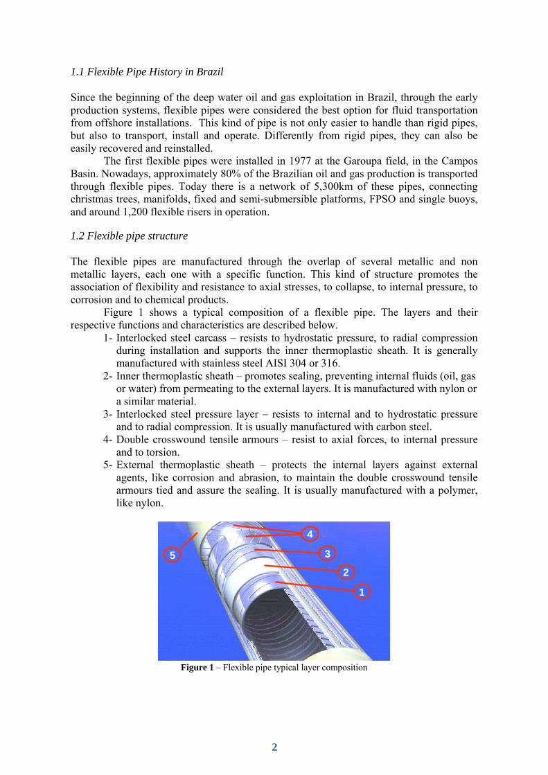
Figure 1 shows a typical composition of a flexible pipe. The layers and their respective functions and characteristics are described below.
1- Interlocked steel carcass – resists to hydrostatic pressure, to radial compression during installation and supports the inner thermoplastic sheath. It is generally manufactured with stainless steel AISI 304 or 316.
2- Inner thermoplastic sheath – promotes sealing, preventing internal fluids (oil, gas or water) from permeating to the external layers. It is manufactured with nylon or a similar material.
3- Interlocked steel pressure layer – resists to internal and to hydrostatic pressure and to radial compression. It is usually manufactured with carbon steel.
4- Double crosswound tensile armours – resist to axial forces, to internal pressure and to torsion.
5- External thermoplastic sheath – protects the internal layers against external agents, like corrosion and abrasion, to maintain the double crosswound tensile armours tied and assure the sealing. It is usually manufactured with a polymer, like nylon.
5
1
2
3
4
5
1
2
3
4
Figure 1 – Flexible pipe typical layer composition
2
In some flexible pipes the composition may include other layers, besides these related, with specific functions as the outer-wrap, which consists of an external layer to promote anti-abrasion protection, and also an anti-friction layer and thermal insulation.
2. Integrity Assessment of Flexible Risers
For the integrity assessment of flexible risers an in-service inspection program was established, consisting of visual examination, hydrostatic test and surface monitoring procedures (percolated gas and nitrogen injection in the annular space). The adaptation of conventional non destructive techniques is also being tried to this scenario.
PETROBRAS has also developed a spreadsheet that indicates, to each failure mode, the most appropriate inspection or monitoring technique to be used.
2.1 Visual Inspection
Visual inspection is used to evaluate the riser general aspect and structural integrity. It is also applied to verify catenary configuration and possible contact between the riser and the platform or another riser.
To establish inspection frequency, the flexible pipes were classified in three groups, according to the type of application and the fluid transferred, as shown below. Group 1 – risers (dynamic application) - Flexible pipes for oil and gas transfer; - Flexible pipes for water injection; - Hydraulic umbilicals; - Power and fiber optic cables. Group 2 – flowlines (static application) - Flexible pipes for high pressure oil and gas transfer. Group 3 – flowlines (static application) - Flexible pipes for low pressure gas transfer; - Flexible pipes for water injection; - Hydraulic umbilicals; - Power and fiber optic cables. Inspection frequency for flexible pipes: - Group 1 – 3 to 5 years; - Group 2 – 3 to 5 years; - Group 3 – 10 to 15 years.
If necessary, the inspection frequency may be increased due to the damages detected, to the risk in the case of a failure and to the time necessary to carry out the repair or to substitute the pipe.
As a function of the resources used to do the inspection, the flexible riser extension was divided in three segments, with specific survey procedures. The lower segment
3
comprises the length from the riser/flow connection up to 30m water depth, which is checked through ROV or saturated divers. The following section goes from the top of the lower section up to the water line, the inspection being performed through shallow divers. From that level up to the connection to the platform the riser condition is verified through absailers.
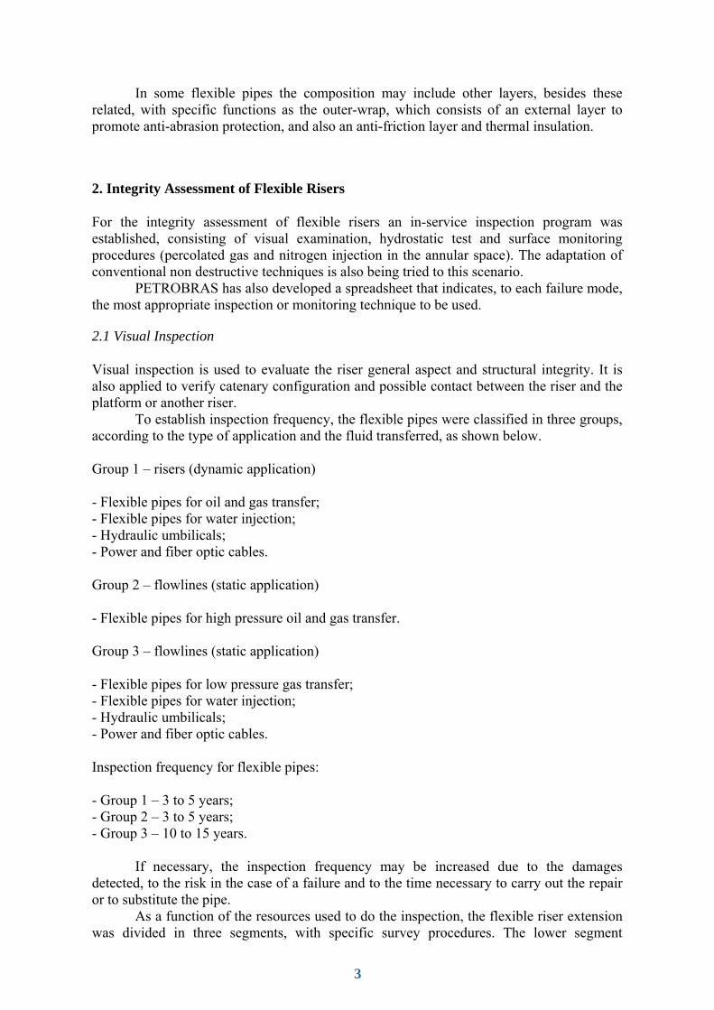
Due to the difficulties found to inspect the riser portion in contact with the sea bottom at the TDP, a device named ARGUS was developed in order to make it possible. It is composed of a winch, on board a ROV support vessel, which operates a hook to hoist the pipe, and an inspection tool. The tool is supplied with wheels and after being coupled to the pipe moves along it, powered by a hydraulic system from a ROV. The inspection tool is also equipped with a pair of rotary wire brushes and water jet, to improve the visualization by a camera (Fig. 2).
Figure 2 – Schematic drawing of ARGUS during inspection of a riser portion
in contact with sea bottom at the TDP.
It is planned to supply the tool with other inspection techniques, like magnetic and ultrasound, and to adapt it to inspect other segments of the flexible pipe, as well as steel catenary risers (SCR) and polyester ropes.
Along the section from 30m water depth up to the surface, the majority of damage occurrences on flexible risers are found, usually caused during installation and operation. Contacts between the riser and the platform or another riser are usually detected, especially at semi-submersible units, due to the platform drift (Fig. 3). These interferences may promote not only damage to the external sheath, but also the rupture of the tensile armours, caused by fatigue or corrosion, and the riser failure.
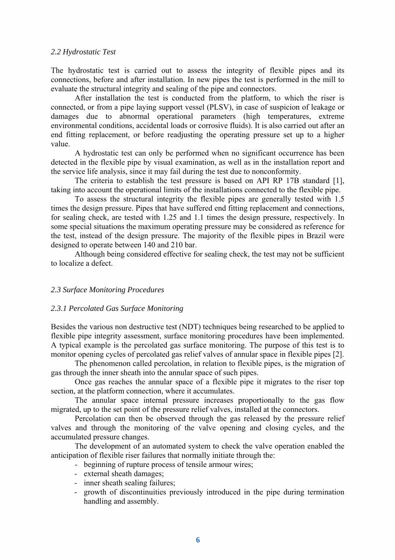
At the I-tube some typical damage processes are detected, like external sheath abrasion caused by the bend stiffener internal insert (Fig. 4), metallic interference between the bend stiffener edge and the tensile armour and also fatigue of the bend stiffener. To have a satisfactory visual access to the riser in this region, the bend stiffener is disconnected from the I-tube by shallow water divers every year, to carry out the survey according to the in-service inspection program.
4
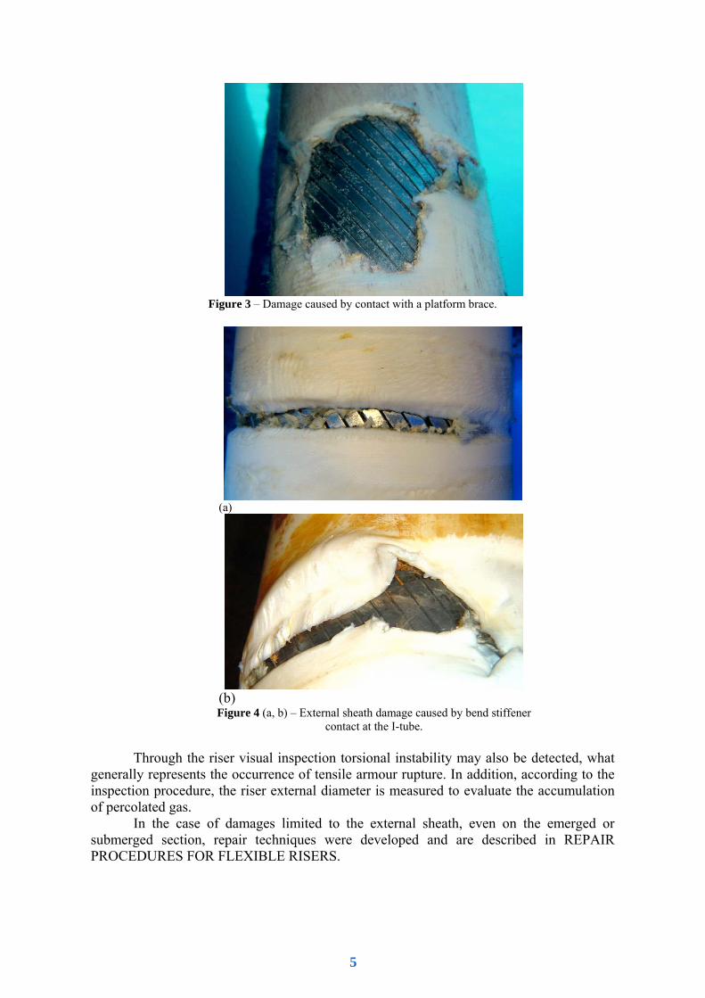
Figure 3 – Damage caused by contact with a platform brace.
(a)
(b)
Figure 4 (a, b) – External sheath damage caused by bend stiffener contact at the I-tube.
Through the riser visual inspection torsional instability may also be detected, what
generally represents the occurrence of tensile armour rupture. In addition, according to the inspection procedure, the riser external diameter is measured to evaluate the accumulation of percolated gas.
In the case of damages limited to the external sheath, even on the emerged or submerged section, repair techniques were developed and are described in REPAIR PROCEDURES FOR FLEXIBLE RISERS.
5
2.2 Hydrostatic Test
The hydrostatic test is carried out to assess the integrity of flexible pipes and its connections, before and after installation. In new pipes the test is performed in the mill to evaluate the structural integrity and sealing of the pipe and connectors.
After installation the test is conducted from the platform, to which the riser is connected, or from a pipe laying support vessel (PLSV), in case of suspicion of leakage or damages due to abnormal operational parameters (high temperatures, extreme environmental conditions, accidental loads or corrosive fluids). It is also carried out after an end fitting replacement, or before readjusting the operating pressure set up to a higher value.
A hydrostatic test can only be performed when no significant occurrence has been detected in the flexible pipe by visual examination, as well as in the installation report and the service life analysis, since it may fail during the test due to nonconformity.
The criteria to establish the test pressure is based on API RP 17B standard [1], taking into account the operational limits of the installations connected to the flexible pipe.
To assess the structural integrity the flexible pipes are generally tested with 1.5 times the design pressure. Pipes that have suffered end fitting replacement and connections, for sealing check, are tested with 1.25 and 1.1 times the design pressure, respectively. In some special situations the maximum operating pressure may be considered as reference for the test, instead of the design pressure. The majority of the flexible pipes in Brazil were designed to operate between 140 and 210 bar.
Although being considered effective for sealing check, the test may not be sufficient to localize a defect.
2.3 Surface Monitoring Procedures
2.3.1 Percolated Gas Surface Monitoring
Besides the various non destructive test (NDT) techniques being researched to be applied to flexible pipe integrity assessment, surface monitoring procedures have been implemented. A typical example is the percolated gas surface monitoring. The purpose of this test is to monitor opening cycles of percolated gas relief valves of annular space in flexible pipes [2].
The phenomenon called percolation, in relation to flexible pipes, is the migration of gas through the inner sheath into the annular space of such pipes.
Once gas reaches the annular space of a flexible pipe it migrates to the riser top section, at the platform connection, where it accumulates.
The annular space internal pressure increases proportionally to the gas flow migrated, up to the set point of the pressure relief valves, installed at the connectors.
Percolation can then be observed through the gas released by the pressure relief valves and through the monitoring of the valve opening and closing cycles, and the accumulated pressure changes.
The development of an automated system to check the valve operation enabled the anticipation of flexible riser failures that normally initiate through the:
- beginning of rupture process of tensile armour wires; - external sheath damages; - inner sheath sealing failures; - growth of discontinuities previously introduced in the pipe during termination
handling and assembly.
6
The monitoring system is integrated to the platform automation control center, in order to provide continuous data of gas pressure inside the annular space and valve operation cycle to operators.
It is important to emphasize that such defects are located in areas usually difficult to access for conventional nondestructive inspection techniques. 2.3.2 Nitrogen Injection in the Annular Space The damage concentration on the flexible riser top section became critical at FPSO and FSO, since the access to the risers at the I-tubes has not been considered during turret design. The nitrogen injection in the annular space was first carried out in these units and then, based on the good results obtained, it was introduced in other installations.
The purpose of this test is to assess the external sheath integrity, from the flexible riser connection to the platform down to 30m water depth, through the injection of nitrogen in the annular space. The test also promotes the sheath integrity evaluation beneath the accessories, like the bend stiffener and the stopper, without being necessary to remove them.
Taking into account that gas relief valves, installed at the flexible riser connector, are calibrated according to the pipe manufacturer design parameters, the nitrogen injection pressure shall not exceed the valve set up value, under the risk of causing damage to the thermoplastic sheath or changing the valve set up.
During the test the following data shall be registered: - nitrogen injection pressure; - stabilization pressure; - injection time; - stabilization time; - injected volume; - the existence of any leakage and any eventual pressure relief valve opening. The nitrogen injection shall be interrupted as soon as pressure stabilization is
achieved or any pressure relief valve opening or injection flux interruption is observed. The interpretation of the registered data provides the identification and localization of damages at the sheath that have reached the tensile armour.
This test is not intended to substitute the visual survey, but its results can be used to optimize the shallow diver inspection. 2.3.3 Deformation monitoring For the emerged riser section, besides the periodical inspection carried out by absailers, a surface monitoring procedure was implemented for the integrity assessment in relation to torsion or deformation in general. It consists of painting a 4,000x20mm longitudinal band on each riser, with two circumferential bands, 20mm wide, at each end. In every inspection the band shall be photographed for further comparisons.
It is planned to develop a device, to be installed on this riser section, which will ring an alarm in the control room in case of excessive torsion.
2.3.4 Visual Inspection through Video Camera In FPSO and FSO, since the flexible riser top section is inside the I-tube, a visual inspection through a video camera is also carried out from the surface. The camera, that shall be appropriate to operate in explosive atmospheres, is inserted through an inspection
7
window at the top of the I-tube. The purpose of this test is to assess the integrity of the external sheath, in relation to damages or deformations, and also check the bend stiffener fixation, the condition of eventual repairs on the sheath and evaluate the presence of debris inside the I-tube, which may damage the flexible riser.
To facilitate the detection and identification of sealing failures on the external sheath, the test may be performed simultaneously with the nitrogen injection test, as described in the section Nitrogen Injection in the Annular Space.
Another video inspection system named Reversed Periscope, also operated from the surface, has been developed. It promotes continuous and low cost monitoring of the bend stiffener and riser top section integrity, since the device substitutes the shallow diving intervention.
2.3.5 Non Destructive Technique Trials for the Integrity Assessment of Flexible Pipes Since flexible pipes are complex structures, composed of several layers manufactured with different metallic and non metallic materials, the dissimilarities in chemical and physical properties make it difficult to use conventional NDT techniques in the inspection of these pipes. So, to improve the integrity assessment and, consequently, the reliability of flexible pipes, PETROBRAS is investing in NDT and monitoring techniques.
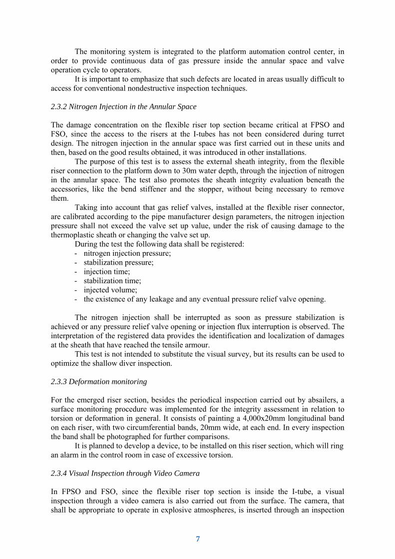
The experience with the inspection and maintenance of flexible pipes indicates that the major causes of failure are [3]:
- armour wire rupture caused by fatigue at the interface tube/end fitting (Fig. 5); - inner sheath sealing failure due to degradation; - dislocation inside end fitting; - corrosion of armour layer and carcass; - torsional instability. X-ray and electromagnetism are NDT techniques with possible application to
flexible pipe inspection, especially eddy currents [4]. PETROBRAS R&D Center has done some laboratory research, with good results,
trying to detect armour misalignment with X-ray and ultrasound. Another possibility of ultrasound application is the detection of polymeric layer degradation by abnormal heating. The use of ultrasound inspection avoids the necessity of time consuming physical chemical analysis [5].
Figure 5 – Armour wire rupture
A lot of atmospheric tests were done using X-Ray, trying to detect armour wire
rupture inside the end fitting, without success. So as to penetrate the huge mass of metal
8
with radiation, a linear accelerator was used. Despite the good images obtained, broken wires were not detected (Fig. 6).
Figure 6 – Linear accelerator X-Ray image inside connector
Laboratory tests were also done with an eddy current inspection device, developed to detect cracks and corrosion crevices in the tensile armour and carcass layers. The discontinuity detection sensitivity was quite good, but the inspection speed was so slow that was impossible to cover the complete length of a flexible pipe.
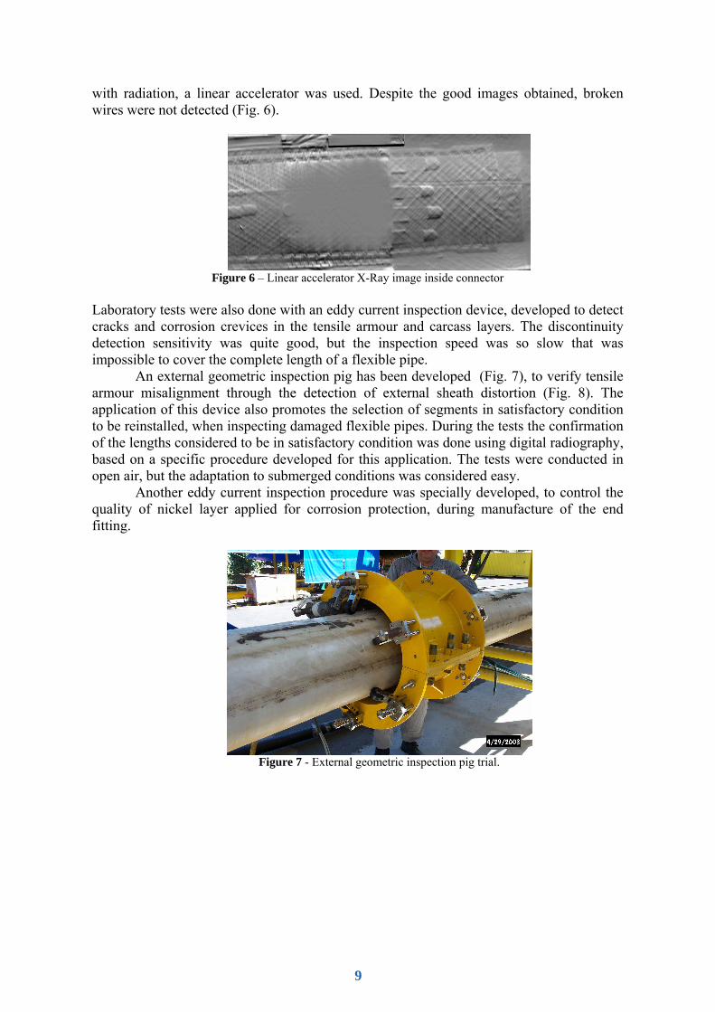
An external geometric inspection pig has been developed (Fig. 7), to verify tensile armour misalignment through the detection of external sheath distortion (Fig. 8). The application of this device also promotes the selection of segments in satisfactory condition to be reinstalled, when inspecting damaged flexible pipes. During the tests the confirmation of the lengths considered to be in satisfactory condition was done using digital radiography, based on a specific procedure developed for this application. The tests were conducted in open air, but the adaptation to submerged conditions was considered easy.
Another eddy current inspection procedure was specially developed, to control the quality of nickel layer applied for corrosion protection, during manufacture of the end fitting.
Figure 7 - External geometric inspection pig trial.
9

Figure 8 - Tensile armour misalignment detected through geometric inspection pig.
3. Conclusion
The described surface monitoring procedures, associated with a guided inspection to check the acquired data, are being considered the best option for the integrity assessment of flexible risers. Good results are being obtained in identification of certain damages and anticipation of possible failures, as well as in shallow diver inspection optimization.
Studies are still underway to adapt NDT techniques for the inspection of flexible risers, even in service or in the selection of segments in satisfactory condition to be reinstalled.
Inspection tools are also under development. Up to now the external geometric inspection pig, besides the good results obtained in the atmospheric tests, has presented easy adaptation to submerged conditions.
PETROBRAS offshore oil production will be extended to 1,800m water depth next year, through flexible risers. All the developments achieved in integrity assessment and repair of these structures will be the basis to face the challenges to come.
4. Acknoeledgments
The authors acknowledge Luiz Claudio de Marco Meniconi and Alexandre Meirelles Pope, from PETROBRAS R&D Center, and Theodoro Antoun Netto, from COPPE/UFRJ, for the support and valuable suggestions.
5. References
[1] API RP 17B, Recommended Practice for Flexible Pipe, 2nd Edition, July, 1998. [2] Felix-Henry, A., Lembeye, P., 2004, “Flexible Pipes in-Service Monitoring”, 23rd International
Conference on Offshore Mechanics and Artic Engineering, Vancouver, British Columbia, Canada, paper OMAE2004-51348.
[3] Souza, L. A. L. e , Simões Filho, S., and Almeida, M. C. de , 2003, "Flexible Line Inspection Methodology Based on IBR", Final Report of PETROBRAS Research & Development Project 600544, Brazil (in Portuguese).
10

[4] Otteren A., and Midtgaard Φ., "Internal Inspection of Flexible Riser on the Troll B Platform", Norsky Hydro Research Centre Report, Bergen, Norway.
[5] Carneval, R. O., Costa, L. C. S., Lontra Filho, L. L., Santos, J. M. dos, Almeida, M. C. de , and Souza, L. A. L. e, 2005, "Flexible Line Inspection", IX International Chemical and Petroleum Industry Inspection Technology Conference, Houston, TX, USA.
11