flexible labyrinth system in reciprocating compressors … · in reciprocating compressors for...
TRANSCRIPT

Fig. 2:
Leakages in dependence on eccentricity
Flexible Labyrinth System in Reciprocating Compressors for Special Applications
By Gerhard Knop and Klaus Hoff
Beside the comprehensive possibilities of control, the working chambers’ highleak tightness , compared with rotary machines, is an important positive featureof reciprocating compressors. Thus gases can be compressored economically,even with high pressures. For this job applications with contacting sealing ele-ments have proved their value for a long time. However, there are also applica-tions arguing for a sealing system that is not based on a sealing contact. Exam-ples for these applications are
n
gases with particles that have an abrasive effect
n
gases with tendency to polymerisation
n
oxygen because of the danger of fires
n
compressors with long uninterrupted continuous operation; however, herehigher leakages have to be put up with.
Beside the classical labyrinth systems there are also principles that try to combinethe advantages of contacting rings and pure labyrinths. Such a system (flexiblelabyrinth) was presented by Nickol [1] as early as in 1997. Since then furtherstudies were conducted for optimising these principles and correspondingmeasures were implemented. These are going to be explained below.
Piston rings’ design in flexible labyrinth
First at short description is given of theflexible labyrinth’s “heart”. The basic ideais to realise the small gap that is necess-ary for the small leakage by ensuringthat seal ring that are contacting first,rest against their shoulder after a specialrunning-in period (
Fig. 1
). From this timeon, the seal rings release the smallestpossible gap matching the cylinder bore.The better the piston’s radial guidance is,the longer this favourable condition, asfar as small leakage is concerned, ismaintained.
Guidance of piston and piston rod
The guidance of pistons and piston rodswith contacting rings is usually made atcrosshead and piston, whereupon thepistons’ guidance is ensured by means ofguide rings (
Fig. 3a
). Since only theguide rings fix the piston radially, theywear by-and-by and the eccentricity be-tween piston and cylinder bore increas-
es. However, the purpose of a labyrinthsealing is to largely avoid the eccentricitysince otherwise leakages would riseabove average (
Fig. 2
).
In order to keep eccentricity small, an up-per piston rod guidance was developed[1], (
Fig. 3b
), ensuring the piston’s cen-tric guidance. Thus it was possible torefrain from guide rings at the piston.However, this design is quite complicatedand it is not easy to realise the requiredsmall wear of the upper guidance. That iswhy further possibilities were examined.These resulted in a lower rod guidance(
Fig. 3c
), as also used for classical laby-rinth compressors. Here, too, it is theo-retically possible to refrain from guide
Fig. 1:
Flexible labyrinth system before (left) and after (right) the running-in period [1]
rings at piston. However, due to vibration-al reasons (see below), a guide ring isgenerally installed (
Fig. 3d
). But due tothe lower rod guidance this ring is radiallystrongly relieved so that it hardly wears.With this design it is also possible to in-stall the labyrinth system if piston diame-ters are above 500 mm.
Layout of lower guide bearing
As far as the design is concerned, thelower guide bearing is nothing else thana friction-type bearing, as fitted at thecrankshaft. Together with the oil wiperpacking it forms a unit (
Fig. 4
). The bear-ing has a small radial gap and is oil-lubri-cated. The compressor’s additional oil re-quirement is so small that it can be ne-glected.
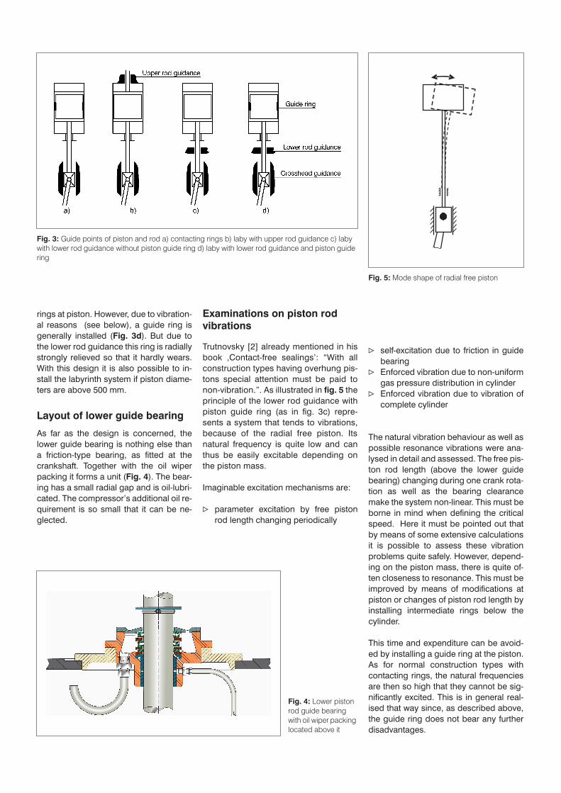
Examinations on piston rod vibrations
Trutnovsky [2] already mentioned in hisbook ‚Contact-free sealings’: “With allconstruction types having overhung pis-tons special attention must be paid tonon-vibration.”. As illustrated in
fig. 5
theprinciple of the lower rod guidance withpiston guide ring (as in fig. 3c) repre-sents a system that tends to vibrations,because of the radial free piston. Itsnatural frequency is quite low and canthus be easily excitable depending onthe piston mass.
Imaginable excitation mechanisms are:
n
parameter excitation by free pistonrod length changing periodically
n
self-excitation due to friction in guidebearing
n
Enforced vibration due to non-uniformgas pressure distribution in cylinder
n
Enforced vibration due to vibration ofcomplete cylinder
The natural vibration behaviour as well aspossible resonance vibrations were ana-lysed in detail and assessed. The free pis-ton rod length (above the lower guidebearing) changing during one crank rota-tion as well as the bearing clearancemake the system non-linear. This must beborne in mind when defining the criticalspeed. Here it must be pointed out thatby means of some extensive calculationsit is possible to assess these vibrationproblems quite safely. However, depend-ing on the piston mass, there is quite of-ten closeness to resonance. This must beimproved by means of modifications atpiston or changes of piston rod length byinstalling intermediate rings below thecylinder.
This time and expenditure can be avoid-ed by installing a guide ring at the piston.As for normal construction types withcontacting rings, the natural frequenciesare then so high that they cannot be sig-nificantly excited. This is in general real-ised that way since, as described above,the guide ring does not bear any furtherdisadvantages.
Fig. 3:
Guide points of piston and rod a) contacting rings b) laby with upper rod guidance c) laby with lower rod guidance without piston guide ring d) laby with lower rod guidance and piston guide ring
Fig. 4:
Lower piston rod guide bearing with oil wiper packing located above it
Fig. 5:
Mode shape of radial free piston

Analysing cylinder cooling
As far as the installation of dry-running,contacting piston rings is concerned, ananalysis of finite elements was made inorder to get information on heat flowsand temperature distributions in the cylin-der.
Fig. 6
shows an example with thecold suction side on the left and thewarmer discharge side on the right. Asexpected, the highest temperaturescome about in the piston’s running range(red). In addition to a series of partial re-sults, two basic facts were confirmedonce again:
1. The main share of heat input in the cyl-inder does not result from the gas dis-charge temperature after compres-sion, but from the contacting pistonrings’ friction.
2. The by far largest share of heat storedin the cylinder is discharged via thecooling water. Other cooling ways(gas, ambiance) only take a second-ary effect.
If these findings are translated into laby-rinth compressors, point 1 allows theconclusion that here a cylinder cooling isnot necessary since hardly any frictionalheat is generated. However, in practicecylinders of labyrinth compressors arealso cooled in order to minimse the cylin-der’s thermal distortion. The objective isto keep leakages small by means of con-centricity and axial straightness being asperfect as possible (see also fig. 2).
Design of labyrinth piston rod packing
Just as for the piston, here, too, the laby-rinth section is a lining-up of gaps andvolumes. In 1996 Heinrichs [3] analysedthese geometries theoretially as well asexperimentally and optimised them. Inthis context he also developed a softwareby means of which is became possible tocalculate the level of leakages in depend-ence on all relevant parameter. Since thevarious parameter – in particular the sizeof local gaps – are not constant, but varyby and by, the calculatory forecasting candeviate from reality in a certain range ofdispersion. This problem is dealt with byadding corresponding safety allowancesso that finally leakage is predicted withsuitable accuracy. The number of rings isoptimised for each application. Maximimpressures for such a packing are about60 bar. If pressures were beyond thisvalue, the packing would require an in-
stallation height being no longer practi-cable. In general a high speed is aimed atsince this reduces leakages even further.
The design of a labyrinth packing isshown in
fig. 7
[4]. The seal rings areone-piece and with regard to their radialclearance they are designed in a way thateven with most unfavourable temperatureconditions there is still a small residualclearance between labyrinth ring and pis-ton rod. In comparison with synthetic ma-terials (PTFE or PEEK), the low thermalexpansion coefficient of artificial carbonsbeing used as seal ring material here,is helpful. Mostly the seal rings areequipped with axial springs having, ac-cording to experience, a positive effect onwear. Thus a well designed labyrinthpacking reaches considerably higher life-times than a contacting packing; how-ever, higher leakages have to be takeninto consideration.
Practical example
An air compressor with a rod diameterof 70 mm, 20 bar discharge pressureand 2,900 (standard) m
3
/h flow rate,equipped with the flexible labyrinth andthe piston guidance as per fig. 3d (lowerguide bearing plus piston guide ring),had a leakage of about 25 (standard)m
3
/h. After about 17,000 hours the guidering wear was still not worth mentioning.
Summary
For most applications the contactingrings are still the preferred alternative,since with dry-run their leakage is mini-mal while their lifetimes are good. Forthose applications that require a labyrinthpacking, for example because of abrasiveingredients of gas, the flexible labyrinthdescribed herein is a recommendable so-lution.
Fig. 6:
Temperature distribution in the cyl-inder (finite element model – sectional view)
Fig. 7:
Design of a labyrinth packing [4]

List of references
[1] Johannes Nickol, NEUMAN & ESSER Ma-schinenfabrik, Übach-Palenberg, Kolben-kompressoren mit Kolbendichtung durchflexibles Labyrinth (Reciprocating com-pressor with piston packing by means offlexible labyrinth), Industriepumpen +Kompressoren, Issue 2, May 1997
[2] Karl Trutnovsky, Kazunari Komotori, Be-rührungsfreie Dichtungen, 4. Auflage(Contact-free packing, 4th issue), VDI –Verlag 1981
[3] Klaus Heinrichs WTZ - Roßlau, JohannesNickol, NEUMAN & ESSER Maschinenfa-
brik, Übach-Palenberg, Untersuchungenzur Optimiereung berührungsloser Kol-benstangendichtungen (Studies for opti-mising contact-free piston rod packings),
Industriepumpen + Kompressoren, Is-sue 4, December 1996
[4] STASSKOL KolbenstangendichtungenGmbH, Staßfurt
Dr.-Ing. Klaus Hoff
NEUMAN & ESSER GmbH & Co. KG, Übach-PalenbergPhone: +49(0)2451 [email protected]
Gerhard Knop
NEUMAN & ESSER GmbH & Co. KG, Übach-PalenbergPhone: +49(0)2451 [email protected]
Print from „Industriepumpen + Kompressoren“, issue 2, May 2006, pages 83–86 · Vulkan-Verlag, Huyssenallee 52–56, 45127 Essen, Germany