flexi soft - lc automation flexi soft... · 6.5.9 function block edge detection ... the flexi soft...
TRANSCRIPT

O P E R A T I N G I N S T R U C T I O N S
GB
Flexi Soft
Software Flexi Soft Designer

Operating Instructions
Flexi Soft Designer
2 © SICK AG • Industrial Safety Systems • Germany • All rights reserved 8012479/2008-07-07
This document is protected by the law of copyright, whereby all rights established therein remain with the company SICK AG. Reproduction of this document or parts of this document is only permissible within the limits of the legal determination of Copyright Law. Alteration or abridgement of the document is not permitted without the explicit written approval of the company SICK AG. Microsoft, Windows 98, Windows ME, Windows 2000, Windows XP and .NET. Framework are registered trademarks of Microsoft Corporation. Other product names and trademarks mentioned in these operating instructions are trademarks or registered trademarks of the respective owners.

Operating instructions
Flexi Soft Designer
8012479/2008-07-07 © SICK AG • Industrial Safety Systems • Germany • All rights reserved 3
Contents
Contents 1 About this document ......................................................................................................6
1.1 The Flexi Soft software operating instructions ....................................................6 1.2 Target group ..........................................................................................................6 1.3 Function and structure of these software operating instructions ........................6
1.3.1 Recommendations for familiarising yourself with Flexi Soft Designer...............................................................................................7
1.3.2 Recommendations for experienced users.........................................7 1.4 Scope and version.................................................................................................7 1.5 Symbols and notations used ................................................................................7
2 On safety..........................................................................................................................8 2.1 Specialist personnel..............................................................................................8 2.2 Correct use ............................................................................................................8
3 Installation and removal.............................................................................................. 10 3.1 System requirements......................................................................................... 10 3.2 Installation.......................................................................................................... 10 3.3 Update ................................................................................................................ 10 3.4 Removal.............................................................................................................. 10
4 The graphical user interface ....................................................................................... 11 4.1 Start view............................................................................................................ 11 4.2 Setting the desired language ............................................................................ 11 4.3 Standard views................................................................................................... 12 4.4 Positioning windows........................................................................................... 13 4.5 "Hardware configuration" standard view .......................................................... 13
4.5.1 Exercise for configuring the Flexi Soft modules ............................. 15 4.5.2 Exercise for configuring the connected devices............................. 15
4.6 Logic editor standard view................................................................................. 16 4.6.1 Exercise for using the logic editor ................................................... 16
4.7 Report standard view......................................................................................... 17 4.7.1 Exercise for the Report standard view............................................ 17
4.8 Diagnostics standard view................................................................................. 17
5 Configuring connected devices .................................................................................. 18
6 Logic programming – Function blocks ................................................................ 19 6.1 Function block overview .................................................................................... 20 6.2 Function block properties.................................................................................. 22 6.3 Input and output signal connections of function blocks.................................. 22
6.3.1 Function block input connections ................................................... 22 6.3.2 Single-channel evaluation ............................................................... 23 6.3.3 Dual-channel equivalent evaluation ............................................... 23 6.3.4 Dual-channel complementary evaluation....................................... 24 6.3.5 Dual dual-channel equivalent evaluation ....................................... 24 6.3.6 Dual dual-channel complementary evaluation............................... 25 6.3.7 Output connections of the function block ...................................... 27
6.4 Parameterisation of function blocks................................................................. 28 6.4.1 Discrepancy time.............................................................................. 28 6.4.2 Synchronisation time ....................................................................... 30 6.4.3 Fault present .................................................................................... 31

Operating Instructions
Flexi Soft Designer
4 © SICK AG • Industrial Safety Systems • Germany • All rights reserved 8012479/2008-07-07
Contents
6.5 Logic function blocks..........................................................................................32 6.5.1 Logic function block NOT..................................................................32 6.5.2 Logic function block AND .................................................................33 6.5.3 Logic function block OR....................................................................35 6.5.4 Logic function block Exclusive OR (XOR) .........................................38 6.5.5 Logic function block Exclusive NOR (XNOR)....................................39 6.5.6 Logic function block ROUTING 1:N ..................................................40 6.5.7 Logic function block ROUTING N:N..................................................41 6.5.8 Function block RS flip-flop ...............................................................42 6.5.9 Function block Edge detection ........................................................43 6.5.10 Function block Clock generator .......................................................44 6.5.11 Function blocks Up counter, Down counter and Up/Down
counter ..............................................................................................45 6.6 Application-specific function blocks ..................................................................49
6.6.1 Application-specific function block RESET ......................................49 6.6.2 Application-specific function block RESTART..................................51 6.6.3 Application-specific function block Emergency stop ......................52 6.6.4 Application-specific function block Light curtain evaluation
(ESPE)................................................................................................54 6.6.5 Application-specific function block Evaluation switch....................55 6.6.6 Application-specific function block Two-hand control (Type
IIIA, Type IIIC).....................................................................................58 6.6.7 Application-specific function block OFF delay.................................61 6.6.8 Application-specific function block ON delay ..................................62 6.6.9 Application-specific function block Operating mode selector
switch ................................................................................................63 6.6.10 Application-specific function block EDM (External Device
Monitoring)........................................................................................65 6.6.11 Function block Multiple two-hand control .......................................67 6.6.12 Function block Valve monitoring......................................................69 6.6.13 Function block Magnetically operated switch................................. 73
6.7 Function blocks for muting with parallel sensors, sequential sensors and sensors with crossed layout .......................................................................74 6.7.1 General description ..........................................................................74 6.7.2 Muting sensors .................................................................................77 6.7.3 Muting/override lamp.......................................................................77 6.7.4 Parameters of the function block ....................................................78 6.7.5 Information on wiring .......................................................................86 6.7.6 State transition from Stop to Start ..................................................87 6.7.7 Error states and information on resetting.......................................87 6.7.8 Muting with two parallel sensor pairs..............................................87 6.7.9 Muting with sequential layout of sensor pairs ................................90 6.7.10 Function block 2-sensor muting (with crossed sensors) –
Direction of movement only forwards or backwards ......................92 6.7.11 Function block 2-sensor muting (with crossed sensors) –
Material transport in both directions...............................................94 6.8 Function blocks for press applications..............................................................97
6.8.1 Function block Eccentric press contact ..........................................97 6.8.2 Universal press contact..................................................................102 6.8.3 Function block Press set-up...........................................................108 6.8.4 Function block Press single stroke................................................111 6.8.5 Function block Press automatic ....................................................115

Operating instructions
Flexi Soft Designer
8012479/2008-07-07 © SICK AG • Industrial Safety Systems • Germany • All rights reserved 5
Contents
6.8.6 Function block Press with N-PSDI mode....................................... 117
7 Transferring the system configuration..................................................................... 125 7.1 Transferring project data to the safety controller .......................................... 125 7.2 Compatibility check.......................................................................................... 125 7.3 Verification of the configuration...................................................................... 125 7.4 Activating the write protection of the configuration in the control
system............................................................................................................... 130
8 Device states of the Flexi Soft system..................................................................... 131 8.1.1 Change in the device state ............................................................ 132 8.1.2 Auto Start mode and normal state................................................ 133
9 Technical commissioning.......................................................................................... 134 9.1 Wiring and voltage supply................................................................................ 134 9.2 Transferring the configuration......................................................................... 134 9.3 Technical test and commissioning.................................................................. 135
10 Troubleshooting and error elimination..................................................................... 136

Chapter 1 Operating instructions
Flexi Soft Designer
6 © SICK AG • Industrial Safety Systems • Germany • All rights reserved 8012479/2008-07-07
About this document
1 About this document Please read this chapter carefully before working with these software operating instructions and the Flexi Soft system.
1.1 The Flexi Soft software operating instructions For the Flexi Soft system there are three operating instructions with clearly distinguished fields of application as well as brief instructions for each module.
The mounting instructions are enclosed with each Flexi Soft module. They inform on the basic technical specifications of the modules and contain simple mounting instructions. Use the mounting instructions when mounting Flexi Soft safety controllers.
The Flexi Soft hardware operating instructions describe all the Flexi Soft modules and their functions in detail. Use the Hardware operating instructions in particular to configure Flexi Soft safety controllers.
The Flexi Soft software operating instructions describe the software-supported configura-tion and parameterization of the Flexi Soft safety controllers. In addition, the software operating instructions contain the description of the diagnostics functions that are important for operation and detailed information for the identification and elimination of errors. Use the Software operating instructions in particular for the configuration, commissioning and operation of Flexi Soft safety controllers.
1.2 Target group The Flexi Soft software operating instructions are addressed to planning engineers, designers and operators of systems into which a Flexi Soft modular safety controller is integrated. It also addresses persons who carry out initial commissioning or who are in charge of servicing or maintaining a Flexi Soft system.
These software operating instructions do not provide instructions for operating the machine or system in which a Flexi Soft safety controller is integrated. Information of this kind will be found in the operating instructions for the machine or system.
1.3 Function and structure of these software operating instructions
These software operating instructions instruct the technical personnel of the machine manufacturer or machine operator in the software configuration, operation and diagnostics of a Flexi Soft system using the Flexi Soft Designer software. It only applies in combination with the "Flexi Soft Hardware Operating Instructions".
Chapter 2 contains fundamental safety instructions. These instructions must be read.
We also refer you to our homepage on the Internet at
http://www.sens-control.com
There, you can download the following files:
Flexi Soft Designer Hardware and software operating instructions
Note

Operating Instructions Chapter 1
Flexi Soft Designer
8012479/2008-07-07 © SICK AG • Industrial Safety Systems • Germany • All rights reserved 7
About this document
1.3.1 Recommendations for familiarising yourself with Flexi Soft Designer
We recommend the following procedure for users who want to familiarise themselves with Flexi Soft Designer for the first time:
Read chapter 4 to familiarise yourself with the graphical user interface and do the exercises for the configuration of example applications.
1.3.2 Recommendations for experienced users
We recommend the following procedure for experienced users who have already worked with Flexi Soft Designer:
Familiarise yourself with the most recent version of the software by reading chapter 1.4.
The table of contents lists all the functions provided by Flexi Soft Designer. Use the table of contents to obtain information about the basic functions.
1.4 Scope and version These software operating instructions apply for the Flexi Soft software version V1.0.0 and CPU0 and CPU1 firmware version V1.0.0.
1.5 Symbols and notations used Notes provide special information on a device or a software function.
Warning!
A warning indicates concrete or potential dangers. These are intended to protect you from harm and help avoid damage to devices and systems.
Read warnings carefully and follow them!
The names of software menus, submenus, options and commands, selection boxes and windows are highlighted in bold. Example: Click Edit in the File menu.
Keys and key combinations are set in MAJUSCULES.
Key combinations, i.e. keys that are pressed simultaneously, are connected by a +.
Keys that have to be pressed consecutively are connected by a –.
Example: Press CTRL+ALT+DEL (simultaneously). Press F12–2 (consecutively). The designations of the keys are those used on standard keyboards that are labelled in the language of the country of the use. You are possibly using a keyboard with different key designations, e.g. in German.
Note
ATTENTION
Menus and commands
KEYS

Chapter 2 Operating instructions
Flexi Soft Designer
8 © SICK AG • Industrial Safety Systems • Germany • All rights reserved 8012479/2008-07-07
On safety
2 On safety This chapter deals with your own safety and the safety of the equipment operators.
Please read this chapter carefully before working with a Flexi Soft system.
2.1 Specialist personnel The Flexi Soft system must be installed, configured, commissioned and serviced only by specialist personnel. Specialist personnel are defined as persons who
have undergone the appropriate technical training and
have been instructed by the responsible machine operator in the operation of the machine and the current valid safety guidelines
and have access to the Flexi Soft hardware and software operating instructions and have read and familiarised themselves with them.
2.2 Correct use The Flexi Soft Designer software is used to configure a safety controller consisting of modules of the Flexi Soft system.
The Flexi Soft system may only be used by qualified persons and only at the machine at which it was mounted and initially commissioned by a qualified person in accordance with the Flexi Soft hardware and software operating instructions.
SICK AG accepts no claims for liability if the software or the devices are used in any other way or if modifications are made to the software or the devices – even in the context of mounting and installation.
Observe the safety instructions and protective measures of the Flexi Soft hardware and software operating instructions!
When implementing a safety-relevant functional logic, ensure that the regulations of the national and international rules and standards are observed, in particular the controlling strategies and the measures for risk minimisation that are mandatory for your application.
ATTENTION
ATTENTION
ATTENTION

Operating Instructions Chapter 2
Flexi Soft Designer
8012479/2008-07-07 © SICK AG • Industrial Safety Systems • Germany • All rights reserved 9
On safety
When mounting, installing and using the Flexi Soft system, observe the standards and directives applicable in your country.
The national and international rules and regulations apply to the installation and use as well as commissioning and periodic technical inspection of the Flexi Soft safety controller, in particular:
– Machinery Directives 98/37/EC or 2006/42/EC
– EMC Directives 89/336/EC or 2004/108/EC
– Use of Work Equipment Directive 89/655/EEC and the supplementary Directive 35/63/EC.
– Low-Voltage Directive 2006/95/EC.
– Work safety regulations and safety rules
The Flexi Soft hardware and software operating instructions must be made available to the operator of the machine where a Flexi Soft system is used. The machine operator is to be instructed in the use of the device by a qualified person and must be instructed to read the operating instructions.

Chapter 3 Operating instructions
Flexi Soft Designer
10 © SICK AG • Industrial Safety Systems • Germany • All rights reserved 8012479/2008-07-07
Installation and removal
3 Installation and removal
3.1 System requirements Recommended system configuration:
Windows 2000, Windows XP, or Windows Vista
.NET Framework 2.0
1 GHz processor
1 Gbyte work memory
1024 x 768 screen resolution
200 Mbytes free hard disk memory
Flexi Soft Designer is a .NET Framework application. It requires .NET Framework Version 2.0 (included on the Flexi Soft CD-ROM) or higher. Information on the current .NET Framework versions and supported operating systems is available on the Internet at
http://www.microsoft.com/
Microsoft .NET Framework Version 2.0 or higher and any other components that may be needed can also be downloaded from http://www.microsoft.com/downloads/.
3.2 Installation Insert the CD-ROM of the Flexi Soft Designer into the corresponding drive of your computer in order to begin with the installation. If the AutoRun function for CDs is activated on your PC, the start screen is displayed after the CD has been inserted. Click Install Flexi Soft Designer and follow the further instructions.
If the AutoRun function for CDs is not activated on your PC, start the installation manually by running the setup.exe file on the CD-ROM.
3.3 Update The most recent version of the Flexi Soft Designer is available on the Internet at www.sens-control.com. New software versions may contain new functions and support new Flexi Soft modules.
Remove the old software version before installing a new one. The working directory in which the project data are stored is not overwritten during the new installation and is retained.
3.4 Removal The software can be removed as follows:
In the Windows Start menu, start Remove Flexi Soft Designer in the Flexi Soft Designer programme folder.

Operating Instructions Chapter 4
Flexi Soft Designer
8012479/2008-07-07 © SICK AG • Industrial Safety Systems • Germany • All rights reserved 11
The graphical user interface
4 The graphical user interface This chapter familiarises you with the basic elements of the graphical user interface as an introduction. This chapter does not give any information on the configuration of Flexi Soft modules nor any instructions for logic programming. This chapter is only intended to explain the fundamental functioning of the Flexi Soft Designer on the basis of a small section of the functions. Experienced users of Flexi Soft Designer can skip this chapter.
4.1 Start view After the software has been started, the start view is displayed. The user can specify here with which of the following actions he wants to start:
Adapting the parameters of the serial interface
Establishing the connection to a physically connected device
Creating a new project
Opening an existing project file
4.2 Setting the desired language Click the flag icon in the menu bar at the extreme right and select the desired language version.
Note
Fig. 1: Start view with selection of the action
Chapter 4 Operating instructions
Flexi Soft Designer
12 © SICK AG • Industrial Safety Systems • Germany • All rights reserved 8012479/2008-07-07
The graphical user interface
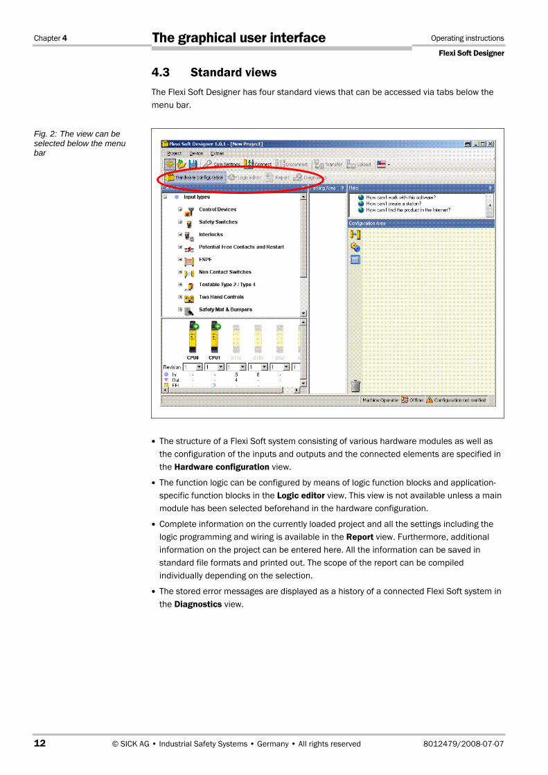
4.3 Standard views The Flexi Soft Designer has four standard views that can be accessed via tabs below the menu bar.
The structure of a Flexi Soft system consisting of various hardware modules as well as the configuration of the inputs and outputs and the connected elements are specified in the Hardware configuration view.
The function logic can be configured by means of logic function blocks and application-specific function blocks in the Logic editor view. This view is not available unless a main module has been selected beforehand in the hardware configuration.
Complete information on the currently loaded project and all the settings including the logic programming and wiring is available in the Report view. Furthermore, additional information on the project can be entered here. All the information can be saved in standard file formats and printed out. The scope of the report can be compiled individually depending on the selection.
The stored error messages are displayed as a history of a connected Flexi Soft system in the Diagnostics view.
Fig. 2: The view can be selected below the menu bar

Operating Instructions Chapter 4
Flexi Soft Designer
8012479/2008-07-07 © SICK AG • Industrial Safety Systems • Germany • All rights reserved 13
The graphical user interface
4.4 Positioning windows Every view consists of several sub-windows that can be positioned freely. You can
change the height, width and position of each sub-window by using the mouse to move the frame or title bar of the sub-window,
convert a sub-window into a flyout window by clicking the "Hide" button (drawing pin symbol) on the right in the title bar. The flyout is then positioned on the left-hand margin of the Flexi Soft Designer window,
move flyout windows back to their normal position by clicking the drawing pin icon in the flyout window again.
4.5 "Hardware configuration" standard view The Hardware configuration window consists of the following sub-windows:
Tabs for switching between the standard views Hardware configuration, Logic editor, Report and Diagnostics.
Menu bar with the menus Project, Device, View, Extras
Toolbar with icons for rapid access to menus that are often used
Selection window Elements; all the devices (e.g. sensors/encoders or actuators/displays, etc.) that can be connected to a Flexi Soft safety controller are listed here. The devices can be parameterized and renamed. In addition, user-defined devices can be created and stored. In addition to the elements, EFI elements can also be connected. They are dragged to the two EFI interfaces of the main module, provided that the main module (e.g. CPU1) provides EFI interfaces.
Fig. 3: Sub-windows can be converted to flyout menus

Chapter 4 Operating instructions
Flexi Soft Designer
14 © SICK AG • Industrial Safety Systems • Germany • All rights reserved 8012479/2008-07-07
The graphical user interface
Parking area; here the user can compile a selection of devices for a concrete application and store them temporarily.
Selection window Modules; all the Flexi Soft hardware modules that can be combined into a Flexi Soft safety controller are listed here. The modules that cannot be selected at the current configuration are greyed out. Modules that can be added to the current configuration are identified by a green "+" symbol. The software version number of the respective module can be selected. The number of inputs, outputs and EFI connections is displayed for each module.
Configuration area; the entire hardware configuration of the Flexi Soft safety controller and of the connected devices is created here and represented graphically. The individual modules and connected devices can be named, have a tag name assigned and can be parameterized. Icons for the functions are located on the left next to the positioned modules: Magnifier, settings and editing tag names (editing the I/O list). When a connection to a Flexi Soft control system is established, further functions are also available: Logging in (changing the user group), verifying (reading in and comparing the configuration) and starting/stopping the CPU.
Fig. 4: The "Hardware configuration" standard view

Operating Instructions Chapter 4
Flexi Soft Designer
8012479/2008-07-07 © SICK AG • Industrial Safety Systems • Germany • All rights reserved 15
The graphical user interface
4.5.1 Exercise for configuring the Flexi Soft modules
Create a new project using Project New. All the Flexi Soft modules are displayed in the Modules selection window. All the modules are greyed out with the exception of the CPUx main modules. Use the mouse to drag a main module (CPU0 or CPU1) into the Configuration area. The main module is displayed magnified there. The inputs/outputs and terminals are visible. The CPU modules are now greyed out and the other I/O modules are displayed in the Modules selection window. Furthermore, the three tabs Logic editor, Report and Diagnostics are now displayed in the toolbar.
Create further Flexi Soft I/O modules in the Configuration area. You can position them freely. Green arrows indicate where the new module will be positioned. Exception: The main module is always located at the extreme left.
Right-click the individual modules and click Edit… in the pop-up menu. Enter a new tag name (module name) for the respective module and close the window by clicking OK.
Change the positions of the modules subsequently by using the mouse to drag them to a different position. Delete the modules by right-clicking the module and clicking Delete in the pop-up menu. Alternatively, use the mouse to drag the module to the recycle bin icon at the bottom left of the Configuration area.
4.5.2 Exercise for configuring the connected devices
The selection structure in the Elements selection window can be expanded by means of a mouse click. Optional: Right-click a device and select Edit mask in the pop-up menu. Assign a user-defined Internal device number if you want to. This Internal device number is stored for this device.
Select some devices from the list and drag them into the Parking area.
The Parking area serves only to increase clarity. You can compile all the required devices here so that you do not forget any of them during the configuration. Alternatively, you can drag the devices directly from the Elements selection window into the Configuration area.
Then drag a device from the Parking area into the configuration area.
If the Configuration area does not contain a module with suitable free inputs/outputs, the device cannot be placed there. In this case, place at least one hardware module with inputs/outputs, e.g. XTIO or XTDI, in the configuration area.
When the device is moved over suitable free inputs/outputs, they light up green. The software automatically considers the required number of inputs/outputs. Drop the device on a suitable position. The device icon is now displayed in the view at this point.
Drag the device to other suitable inputs/outputs or back into the Parking area.
Delete the device by right-clicking the device icon and clicking Delete in the pop-up menu. Alternatively, use the mouse to drag the device to the recycle bin icon at the bottom left of the Configuration area.
A device can be parameterized when it is located in the Parking area or in the Configuration area. Right-click a device in the Parking area or Configuration area and select Edit… from the pop-up menu or double-click a device. The Element settings window is opened. Depending on the type of device you can
– assign a tag name (identifying name for the element)
– set parameters of the device, for example discrepancy times, ON-/OFF-delay times, test pulse active/not active, etc.
Close the Element settings window by clicking OK.
Exercise
Exercise
Note

Chapter 4 Operating instructions
Flexi Soft Designer
16 © SICK AG • Industrial Safety Systems • Germany • All rights reserved 8012479/2008-07-07
The graphical user interface
4.6 Logic editor standard view As soon as at least one Flexi Soft main module is located in the Configuration area, the Logic editor can be accessed via the tab of the same name.
The Flexi Soft Designer includes a graphical logic editor. The function logic is programmed by using logic and application-specific function blocks. The inputs, function blocks and outputs are positioned on a worksheet definable in size and are connected correspondingly.
The Logic editor window consists of the following sub-windows:
Menu bar with the menus Project, Device, View, Extras
Toolbar with icons for rapid access to menus that are often used
Tabs for switching between the standard views Hardware configuration, Logic editor, Report and Diagnostics.
Specific menu bar of the logic editor with the functions Add/Delete pages, Copy/Cut/Paste/Delete elements, Undo/Redo last action, Open the dialog box for editing logic results, Edit/Insert/Delete grid lines,
Selection window for Function blocks, Inputs and Outputs respectively
Info window on the bottom left for displaying the important system resources such as the number of used/available function blocks or the current execution time (cycle time of the logic). When the cursor is moved over a function block in the worksheet, additional information on this function block is displayed in the Info window.
Worksheet (Page) for creating the logic and I/O summary that can be selected alternatively by using a tab.
4.6.1 Exercise for using the logic editor
In the Hardware configuration standard view combine a main module, at least one FX3-XTIO module and one element.
Start the Logic editor by clicking the tab of the same name.
In the selection window for Inputs, Function blocks and Outputs, click Inputs in the centre left and drag an input from the list onto the worksheet.
In the selection window for Inputs, Function blocks and Outputs, click Function blocks in the centre left and drag an application-specific or logic function block from the list onto the worksheet.
In the selection window for Inputs, Function blocks and Outputs click Outputs in the centre left and drag an output from the list onto the worksheet.
Connect the node of the input with an input field of the function block (node) and an output (node) of the function block with the node of the output. To do so, click one node and drag the cursor to the node with which it is to be connected.
Mark the input, function block, output and the connections by dragging with the right-hand mouse button pressed and then position as desired.
A preview of the respective element or the details of a function block are displayed in the Info window (bottom left) when you move the cursor over it.
In order to delete an element or a function block right-click it and then select Delete.
Exercise

Operating Instructions Chapter 4
Flexi Soft Designer
8012479/2008-07-07 © SICK AG • Industrial Safety Systems • Germany • All rights reserved 17
The graphical user interface
4.7 Report standard view Complete information on the respective project is summarised clearly in the Report standard view. This also includes detailed wiring information at the end of the report.
The information to be summarised in a report can be selected individually from an expandable selection list on the left-hand side. The selection is made by clicking the check boxes.
The toolbar in the Report standard view can be used to
have a complete or partial documentation of a project created
store this documentation in the .pdf format on a data medium
update the documentation
enter additional information on the project.
4.7.1 Exercise for the Report standard view
Start the report by clicking the tab of the same name.
Click the check boxes of the components desired for the report in the selection list on the left-hand side. When a check mark is set or removed in the respective upper level, the subordinate levels are marked correspondingly.
After you have completed all the changes in the selection list in the toolbar, click Update. The report is now drawn up in the right-hand window section. It can be saved and printed using the icons in the toolbar.
The Change configuration view tab can be used to select two different views of the configuration information (hardware- or function-oriented).
Detailed information on using the wiring information at the end of the report is available in the Flexi Soft hardware operating instructions.
4.8 Diagnostics standard view In the Diagnostics standard view, all the stored error messages are displayed as a history of a connected Flexi Soft safety controller.
Exercise
Note

Chapter 5 Operating instructions
Flexi Soft Designer
18 © SICK AG • Industrial Safety Systems • Germany • All rights reserved 8012479/2008-07-07
Configuring connected devices
5 Configuring connected devices Configuration and verification of devices that are connected to the safety controller is generally not carried out using the Flexi Soft Designer software, even if they can be addressed via an RS-232 interface of a Flexi Soft module. These devices have their own mechanisms for configuration and verification.
The exception is formed by the EFI sensors connected to the Flexi Soft main module CPU1 (EFI elements from the elements window). These sensors can be configured directly in the Flexi Soft Designer by double-clicking the icon, or alternatively configured and verified locally at the sensor via the RS-232 interface. For this purpose, the SICK configuration and diagnostics software CDS is used.
Note

Operating Instructions Chapter 6
Flexi Soft Designer
8012479/2008-07-07 © SICK AG • Industrial Safety Systems • Germany • All rights reserved 19
Logic programming – Function blocks
6 Logic programming – Function blocks The function logic of the Flexi Soft system is programmed by using function blocks. These function blocks are certified for use in safety-relevant functions if all safety standards are observed during implementation. The following sections provide information on important aspects of using function blocks in the Flexi Soft system.
Solely safety-relevant signals may be used in safety-relevant logic. Ensure that the application fulfils all the applicable standards and regulations!
If you use the function blocks described in this section in safety-relevant applications, you must observe all the safety standards. Safety-relevant signals have to be used for safety input and safety output signals in safety-relevant applications.
The user is responsible for checking that the right signal sources are used for these function blocks and that the entire implementation of the safety logic fulfils the applicable standards and regulations. Always check the mode of operation of the Flexi Soft hardware and of the logic programme in order to ensure that these behave in accordance with your risk reduction strategy.
ATTENTION
Chapter 6 Operating instructions
Flexi Soft Designer
20 © SICK AG • Industrial Safety Systems • Germany • All rights reserved 8012479/2008-07-07
Logic programming – Function blocks
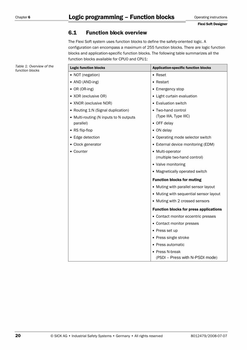
6.1 Function block overview The Flexi Soft system uses function blocks to define the safety-oriented logic. A configuration can encompass a maximum of 255 function blocks. There are logic function blocks and application-specific function blocks. The following table summarizes all the function blocks available for CPU0 and CPU1:
Logic function blocks Application-specific function blocks
NOT (negation)
AND (AND-ing)
OR (OR-ing)
XOR (exclusive OR)
XNOR (exclusive NOR)
Routing 1:N (Signal duplication)
Multi-routing (N inputs to N outputs parallel)
RS flip-flop
Edge detection
Clock generator
Counter
Reset
Restart
Emergency stop
Light curtain evaluation
Evaluation switch
Two-hand control (Type IIIA, Type IIIC)
OFF delay
ON delay
Operating mode selector switch
External device monitoring (EDM)
Multi-operator (multiple two-hand control)
Valve monitoring
Magnetically operated switch
Function blocks for muting
Muting with parallel sensor layout
Muting with sequential sensor layout
Muting with 2 crossed sensors
Function blocks for press applications
Contact monitor eccentric presses
Contact monitor presses
Press set up
Press single stroke
Press automatic
Press N-break (PSDI – Press with N-PSDI mode)
Table 1: Overview of the function blocks
Operating Instructions Chapter 6
Flexi Soft Designer
8012479/2008-07-07 © SICK AG • Industrial Safety Systems • Germany • All rights reserved 21
Logic programming – Function blocks
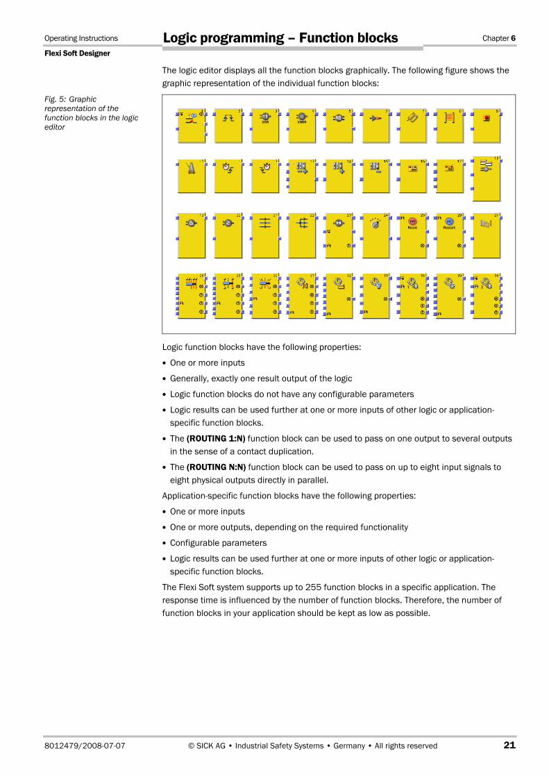
The logic editor displays all the function blocks graphically. The following figure shows the graphic representation of the individual function blocks:
Logic function blocks have the following properties:
One or more inputs
Generally, exactly one result output of the logic
Logic function blocks do not have any configurable parameters
Logic results can be used further at one or more inputs of other logic or application-specific function blocks.
The (ROUTING 1:N) function block can be used to pass on one output to several outputs in the sense of a contact duplication.
The (ROUTING N:N) function block can be used to pass on up to eight input signals to eight physical outputs directly in parallel.
Application-specific function blocks have the following properties:
One or more inputs
One or more outputs, depending on the required functionality
Configurable parameters
Logic results can be used further at one or more inputs of other logic or application-specific function blocks.
The Flexi Soft system supports up to 255 function blocks in a specific application. The response time is influenced by the number of function blocks. Therefore, the number of function blocks in your application should be kept as low as possible.
Fig. 5: Graphic representation of the function blocks in the logic editor

Chapter 6 Operating instructions
Flexi Soft Designer
22 © SICK AG • Industrial Safety Systems • Germany • All rights reserved 8012479/2008-07-07
Logic programming – Function blocks
6.2 Function block properties Function blocks offer a number of different properties that you can use. The configurable parameters differ depending on the function block. You can double-click the function block to access the configurable parameters and select the tab with the desired properties. The following example shows the Evaluation switch function block:
6.3 Input and output signal connections of function blocks Some devices offer a pre-evaluation that makes the use of a special function block with the same evaluation function superfluous. Then, you do not have to carry out this evaluation again in the logic.
6.3.1 Function block input connections
The Flexi Soft system supports applications up to SIL3 (in accordance with EN 62061) and Performance Level (PL) e (in accordance with EN ISO 13849-1). Possible sources for function block inputs are one or two safety signals connected locally to the Flexi Soft safety controller. You can choose between the following input evaluations (depending on the function block):
Single-channel
Dual-channel:
– Dual-channel equivalent
– Dual-channel complementary
– Dual dual-channel equivalent
– Dual dual-channel complementary
Fig. 6: Configurable parameters of function blocks
Note

Operating Instructions Chapter 6
Flexi Soft Designer
8012479/2008-07-07 © SICK AG • Industrial Safety Systems • Germany • All rights reserved 23
Logic programming – Function blocks
The following truth tables summarize the internal evaluation for the individual types of input signal evaluations of the Flexi Soft safety controller.
The fault present is active when the logic processing of the Flexi Soft safety controller detects an error in the combination or in the sequence of the input signals.
6.3.2 Single-channel evaluation
Input 1 Fault present Enable
0 0 0
1 0 1
x 1 0
6.3.3 Dual-channel equivalent evaluation
Input 1 Input 2 Fault present Enable
0 0 0 0
0 1 0 0
1 0 0 0
1 1 0 1
x x 1 0
Note
Fig. 7: Function block for single-channel evaluation
Table 2: Single-channel evaluation
Fig. 8: Function block for dual-channel equivalent evaluation
Table 3: Dual-channel equivalent evaluation

Chapter 6 Operating instructions
Flexi Soft Designer
24 © SICK AG • Industrial Safety Systems • Germany • All rights reserved 8012479/2008-07-07
Logic programming – Function blocks
6.3.4 Dual-channel complementary evaluation
Input 1A Input 1B Fault present Enable
0 0 0 0
0 1 0 0
1 0 0 1
1 1 0 0
x x 1 0
6.3.5 Dual dual-channel equivalent evaluation
Input 1A Input 1B Input 2A Input 2B Fault present Enable
0 0 0 0 0 0
0 0 0 1 0 0
0 0 1 0 0 0
0 0 1 1 0 0
0 1 0 0 0 0
0 1 0 1 0 0
0 1 1 0 0 0
0 1 1 1 0 0
1 0 0 0 0 0
1 0 0 1 0 0
1 0 1 0 0 0
1 0 1 1 0 0
1 1 0 0 0 0
1 1 0 1 0 0
1 1 1 0 0 0
1 1 1 1 0 1
x x x x 1 0
Fig. 9: Function block for dual-channel complementary evaluation
Table 4: Dual-channel with complementary evaluation
Fig. 10: Function block for dual dual-channel equivalent evaluation
Table 5: Dual dual-channel equivalent evaluation

Operating Instructions Chapter 6
Flexi Soft Designer
8012479/2008-07-07 © SICK AG • Industrial Safety Systems • Germany • All rights reserved 25
Logic programming – Function blocks
6.3.6 Dual dual-channel complementary evaluation
Input 1A Input 1B Input 2A Input 2B Fault present Enable
0 0 0 0 0 0
0 0 0 1 0 0
0 0 1 0 0 0
0 0 1 1 0 0
0 1 0 0 0 0
0 1 0 1 0 0
0 1 1 0 0 0
0 1 1 1 0 0
1 0 0 0 0 0
1 0 0 1 0 0
1 0 1 0 0 1
1 0 1 1 0 0
1 1 0 0 0 0
1 1 0 1 0 0
1 1 1 0 0 0
1 1 1 1 0 0
x x X x 1 0
Note that a dual-channel evaluation can already have been carried out at some devices that have been integrated in the hardware configuration. In this case, the XTDI or XTIO I/O device can transfer the result of this evaluation as a single bit via the internal FLEX BUS+. If there is such a pre-evaluation, you can configure the function block on a single-channel input.
Alternatively, you can apply this pre-evaluated input signal bit to both input channels of a function block with a dual-channel input configuration. Pre-evaluated signals can occur in the local input and output definition of the Flexi Soft safety controller or in an I/O device. If you apply a one-bit address to both inputs of the function block, the Flexi Soft safety controller regards the first connection as the logic result and ignores the second connection.
Fig. 11: Function block for dual dual-channel complementary evaluation
Table 6: Dual dual-channel complementary evaluation

Chapter 6 Operating instructions
Flexi Soft Designer
26 © SICK AG • Industrial Safety Systems • Germany • All rights reserved 8012479/2008-07-07
Logic programming – Function blocks
The following function blocks generate the same output value for a dual-channel input signal that was pre-evaluated by the I/O device.
Connect the pre-evaluated signals correctly!
If inputs or outputs for a dual-channel evaluation were pre-evaluated, you have to ensure that the resulting pre-evaluated signal of the dual-channel evaluation is connected as shown in the following graphic. Do not connect both pre-evaluated signals to the function block except if the dual-channel evaluation is to be effected in the function block.
Status information can be available for input signals. In some applications an evaluation of this status information can be important in order to specify the behaviour of the logic functions of the Flexi Soft safety controller. The input status specifies whether the data transferred from the I/O device to the Flexi Soft main module are:
Inactive, because this is the state at the I/O device or
Inactive, because there is a fault at the I/O device.
No category (in accordance with EN 954-1) or SIL or Performance Level (in accordance with EN 62061 or EN ISO 13849-1) is defined for the input behaviour of function blocks since the connection of the safety devices to the inputs is relevant for this purpose and not the connection to the function block itself. However, the following signals in accordance with EN 954-1 can be realised if the connection is effected in accordance with the specified categories:
Input signals up to Category 3 if a dual-channel input with the same test pulse source for both input channels is used
Input signals up to Category 4 if a dual-channel input with different test pulse sources for both input channels is used
Input signals up to Category 4 if two dual-channel inputs with different test pulse sources for both input channel pairs is used
Output signals up to Category 3 if single-channel safety outputs with or without test pulses are used and the necessary requirements for avoiding errors are fulfilled
Output signals up to Category 4 if single- or dual-channel safety outputs with test pulses are used
ATTENTION
Fig. 12: Dual-channel decentralised input with single-channel safety output

Operating Instructions Chapter 6
Flexi Soft Designer
8012479/2008-07-07 © SICK AG • Industrial Safety Systems • Germany • All rights reserved 27
Logic programming – Function blocks
Consult the applicable bodies of rules and regulations as well as standards!
When implementing a safety-relevant functional logic, verify that the controlling strategy and measures for risk minimization fulfil the regulations of the national bodies of rules and regulations. Consult these bodies of rules and regulations as well as standards in order to determine the requirements that have to be fulfilled by your application.
6.3.7 Output connections of the function block
Function blocks provide various output signal connections for connecting to physical outputs or to other function blocks. Possible output signal connections are (depending on the function block):
Enable (enable output)
Enable condition fulfilled (static enable)
Fault present (error output)
Discrepancy error
Synchronisation error
Function test required
EDM error (external device monitoring error)
Reset request (reset required)
Restart request (restart required)
Enable output 1
Enable output 2
The output of a function block cannot be connected to several output elements (physical outputs or EFI outputs), but to several subordinate function blocks. If you want to control several physical outputs with a function block, use the (ROUTING 1:N) function block. The output behaviour of the outputs listed above is explained at the description of the individual function blocks.
You can choose whether error and diagnostics outputs are displayed. In the configuration basic setting of the function blocks only the Enable output and some further outputs are selected (e.g. Reset required). In order to display error and diagnostics outputs increase the number of outputs on the I/O settings tab of the function block properties.
ATTENTION

Chapter 6 Operating instructions
Flexi Soft Designer
28 © SICK AG • Industrial Safety Systems • Germany • All rights reserved 8012479/2008-07-07
Logic programming – Function blocks
6.4 Parameterisation of function blocks In addition to the type of input (e.g. single-channel, dual-channel equivalent, etc.), function blocks can have further parameters that are defined on the properties page of the function block shown above.
The following has to be observed when selecting time monitoring functions for the discrepancy time, synchronisation time, pulse duration, muting time, etc.: The times
• can be selected in 10-ms steps
• have to be greater than the logic execution time
• have a precision of +/– 10 ms in the evaluation
The logic execution time depends on the number and type of the function blocks used and is displayed in the Flexi Soft Designer in the logic editor.
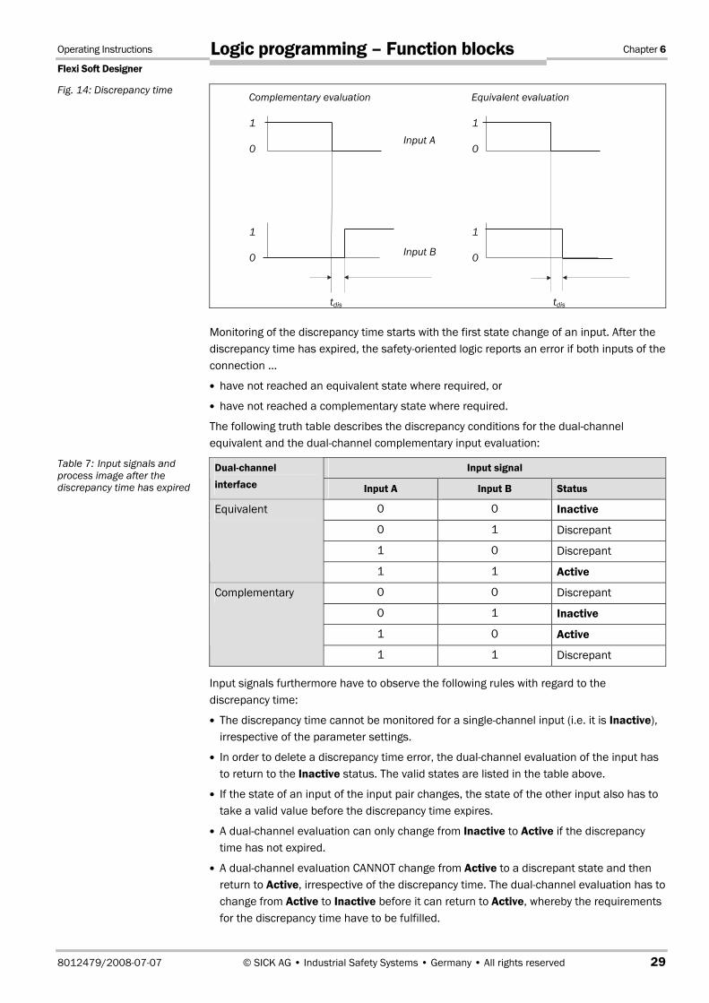
6.4.1 Discrepancy time
The discrepancy time tdis is the maximum time for which the two inputs of a dual-channel evaluation may have invalid states without the safety-oriented logic evaluating this state as an error. At a dual-channel equivalent evaluation both inputs may not be complementary for longer than the configured discrepancy time. At a dual-channel complementary evaluation both inputs may not be equivalent for longer than the configured discrepancy time.
Fig. 13: I/O configuration of the SGATE function block
Note
Evaluation switch function block with configuration basic setting
Evaluation switch function block with all the available inputs and outputs
I/O settings tab of the properties dialog for the Evaluation switch function block
Operating Instructions Chapter 6
Flexi Soft Designer
8012479/2008-07-07 © SICK AG • Industrial Safety Systems • Germany • All rights reserved 29
Logic programming – Function blocks
Monitoring of the discrepancy time starts with the first state change of an input. After the discrepancy time has expired, the safety-oriented logic reports an error if both inputs of the connection …
have not reached an equivalent state where required, or
have not reached a complementary state where required.
The following truth table describes the discrepancy conditions for the dual-channel equivalent and the dual-channel complementary input evaluation:
Input signal Dual-channel interface Input A Input B Status
0 0 Inactive
0 1 Discrepant
1 0 Discrepant
Equivalent
1 1 Active
0 0 Discrepant
0 1 Inactive
1 0 Active
Complementary
1 1 Discrepant
Input signals furthermore have to observe the following rules with regard to the discrepancy time:
The discrepancy time cannot be monitored for a single-channel input (i.e. it is Inactive), irrespective of the parameter settings.
In order to delete a discrepancy time error, the dual-channel evaluation of the input has to return to the Inactive status. The valid states are listed in the table above.
If the state of an input of the input pair changes, the state of the other input also has to take a valid value before the discrepancy time expires.
A dual-channel evaluation can only change from Inactive to Active if the discrepancy time has not expired.
A dual-channel evaluation CANNOT change from Active to a discrepant state and then return to Active, irrespective of the discrepancy time. The dual-channel evaluation has to change from Active to Inactive before it can return to Active, whereby the requirements for the discrepancy time have to be fulfilled.
Fig. 14: Discrepancy time
Table 7: Input signals and process image after the discrepancy time has expired
Complementary evaluation Equivalent evaluation
Input A
Input B
tdis tdis
1
0
1
0
1
0
1
0
Chapter 6 Operating instructions
Flexi Soft Designer
30 © SICK AG • Industrial Safety Systems • Germany • All rights reserved 8012479/2008-07-07
Logic programming – Function blocks
Valid values for the discrepancy time: 0 (no monitoring of the discrepancy time), 10 ms to 30,000 ms in 10-ms steps. If used, the set discrepancy time has to be greater than the logic execution time of the flexible Flexi Soft safety controller.
If a discrepancy error occurs, the error is displayed by the following steps:
Enable changes to Inactive (fail-safe) and
Fault present changes to Active and
Discrepancy error for Pair 1/2 is set to error (for input evaluation 1/2) or
Discrepancy error for Pair 3/4 is set to error (for input evaluation 3/4).
If signals of tested sensors are connected to XTDI and XTIO modules, the discrepancy time has to amount to at least the set test pulse time plus 12 ms, since a signal change at the input of the modules can be delayed by this time.
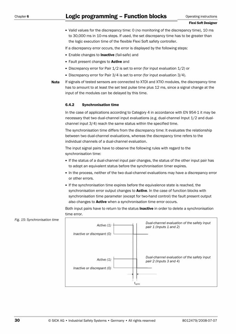
6.4.2 Synchronisation time
In the case of applications according to Category 4 in accordance with EN 954-1 it may be necessary that two dual-channel input evaluations (e.g. dual-channel Input 1/2 and dual-channel input 3/4) reach the same status within the specified time.
The synchronisation time differs from the discrepancy time: It evaluates the relationship between two dual-channel evaluations, whereas the discrepancy time refers to the individual channels of a dual-channel evaluation.
The input signal pairs have to observe the following rules with regard to the synchronisation time:
If the status of a dual-channel input pair changes, the status of the other input pair has to adopt an equivalent status before the synchronisation timer expires.
In the process, neither of the two dual-channel evaluations may have a discrepancy error or other errors.
If the synchronisation time expires before the equivalence state is reached, the synchronisation error output changes to Active. In the case of function blocks with synchronisation time parameter (except for two-hand control) the fault present output also changes to Active when a synchronisation time error occurs.
Both input pairs have to return to the status Inactive in order to delete a synchronisation time error.
Note
Fig. 15: Synchronisation time Dual-channel evaluation of the safety input pair 1 (Inputs 1 and 2)
Dual-channel evaluation of the safety input pair 2 (Inputs 3 and 4)
tsync
Active (1)
Inactive or discrepant (0)
Active (1)
Inactive or discrepant (0)

Operating Instructions Chapter 6
Flexi Soft Designer
8012479/2008-07-07 © SICK AG • Industrial Safety Systems • Germany • All rights reserved 31
Logic programming – Function blocks
6.4.3 Fault present
Various function blocks dispose of the Fault present diagnostics status bit. In order to use it, activate the check box on the I/O settings tab of the function block properties. When you activate the Use Fault Present check box, the additional output "Fault present" is displayed in the function block.
The fault present output informs you about the reason why an enable signal has adopted the Inactive state (fail-safe).
The fault present changes to Active when an error has been detected on the basis of the configured function block parameters (e.g. discrepancy time error, function test error, synchronisation error, etc.).
When the fault present is Active, Enable changes to Inactive (fail-safe). Deleting of the fault present output is described in the section of the respective function block.
Fig. 16: Activating the fault present
Fig. 17: Fault present output

Chapter 6 Operating instructions
Flexi Soft Designer
32 © SICK AG • Industrial Safety Systems • Germany • All rights reserved 8012479/2008-07-07
Logic programming – Function blocks
6.5 Logic function blocks
6.5.1 Logic function block NOT
Function block diagram
General description
The inverted state of Input 1 applies at the output. If, for example, Input 1 is Active, the output is Inactive. This function block evaluates exactly one input.
Never control safety output signals directly with a NOT function block!
Always ensure that the usage of a NOT function lies logically before a Reset function block in your application so that unintentional starting up is prevented. Never control safety output signals directly with a NOT function block.
Truth table
The following applies for the truth tables in this section:
"0" means logic Low or Inactive
"1" means logic High or Active
"x" means "any" = "0" or "1"
Truth table for NOT
Input Output
0 1
1 0
Error states and information on resetting
Logic functions do not carry out monitoring for error conditions.
Fig. 18: Function block diagram for the function block NOT
ATTENTION
Table 8: Truth table for the function block NOT

Operating Instructions Chapter 6
Flexi Soft Designer
8012479/2008-07-07 © SICK AG • Industrial Safety Systems • Germany • All rights reserved 33
Logic programming – Function blocks
6.5.2 Logic function block AND
Function block diagram
General description
The output is Active if all the evaluated outputs are Active. Up to eight inputs are evaluated.
Truth table
See below for truth tables for one to eight inputs. These truth tables use the following designations:
"0" means logic Low or Inactive
"1" means logic High or Active
"x" means "any" = "0" or "1"
Truth table for AND evaluation with one input
Input 1 Output
0 0
1 1
Truth table for AND evaluation with two inputs
Input 1 Input 2 Output
0 x 0
x 0 0
1 1 1
Truth table for AND evaluation with three inputs
Input 1 Input 2 Input 3 Output
0 x x 0
x 0 x 0
x x 0 0
1 1 1 1
Fig. 19: Function block diagram for the function block AND
Table 9: Truth table for AND evaluation with one input
Table 10: Truth table for AND evaluation with two inputs
Table 11: Truth table for AND evaluation with three inputs
Chapter 6 Operating instructions
Flexi Soft Designer
34 © SICK AG • Industrial Safety Systems • Germany • All rights reserved 8012479/2008-07-07
Logic programming – Function blocks
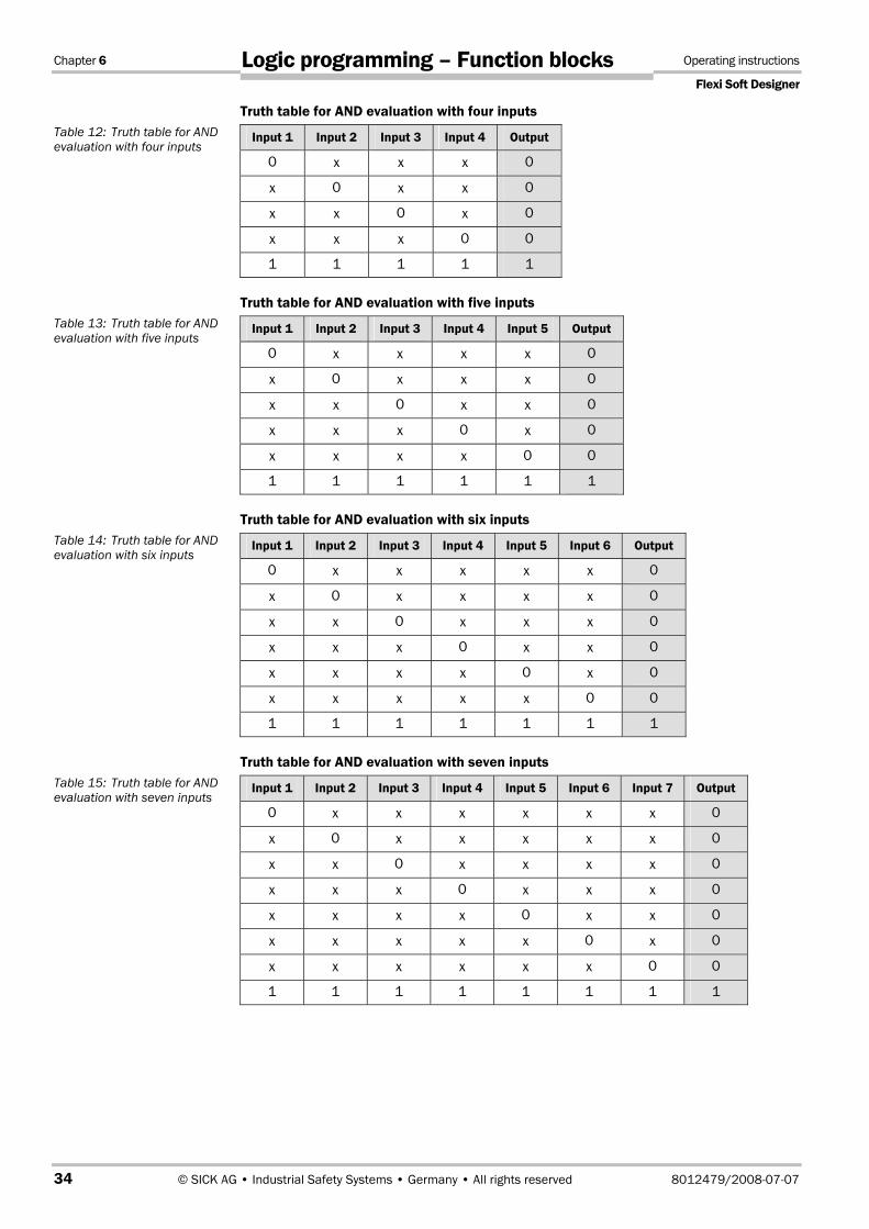
Truth table for AND evaluation with four inputs
Input 1 Input 2 Input 3 Input 4 Output
0 x x x 0
x 0 x x 0
x x 0 x 0
x x x 0 0
1 1 1 1 1
Truth table for AND evaluation with five inputs
Input 1 Input 2 Input 3 Input 4 Input 5 Output
0 x x x x 0
x 0 x x x 0
x x 0 x x 0
x x x 0 x 0
x x x x 0 0
1 1 1 1 1 1
Truth table for AND evaluation with six inputs
Input 1 Input 2 Input 3 Input 4 Input 5 Input 6 Output
0 x x x x x 0
x 0 x x x x 0
x x 0 x x x 0
x x x 0 x x 0
x x x x 0 x 0
x x x x x 0 0
1 1 1 1 1 1 1
Truth table for AND evaluation with seven inputs
Input 1 Input 2 Input 3 Input 4 Input 5 Input 6 Input 7 Output
0 x x x x x x 0
x 0 x x x x x 0
x x 0 x x x x 0
x x x 0 x x x 0
x x x x 0 x x 0
x x x x x 0 x 0
x x x x x x 0 0
1 1 1 1 1 1 1 1
Table 12: Truth table for AND evaluation with four inputs
Table 13: Truth table for AND evaluation with five inputs
Table 14: Truth table for AND evaluation with six inputs
Table 15: Truth table for AND evaluation with seven inputs

Operating Instructions Chapter 6
Flexi Soft Designer
8012479/2008-07-07 © SICK AG • Industrial Safety Systems • Germany • All rights reserved 35
Logic programming – Function blocks
Truth table for AND evaluation with eight inputs
Input 1 Input 2 Input 3 Input 4 Input 5 Input 6 Input 7 Input 8 Output
0 x x x x x x x 0
x 0 x x x x x x 0
x x 0 x x x x x 0
x x x 0 x x x x 0
x x x x 0 x x x 0
x x x x x 0 x x 0
x x x x x x 0 x 0
x x x x x x x 0 0
1 1 1 1 1 1 1 1 1
Error states and information on resetting
Logic functions do not carry out monitoring for error conditions.
6.5.3 Logic function block OR
Function block diagram
General description
The output is Active if any one of the evaluated inputs is Active. Up to eight inputs are evaluated.
Truth table
See below for truth tables for one to eight inputs. These truth tables use the following designations:
"0" means logic Low or Inactive
"1" means logic High or Active
"x" means "any" = "0" or "1"
Truth table for OR evaluation with one input
Input 1 Output
0 0
1 1
Table 16: Truth table for AND evaluation with eight inputs
Fig. 20: Function block diagram for the function block OR
Table 17: Truth table for OR evaluation with one input

Chapter 6 Operating instructions
Flexi Soft Designer
36 © SICK AG • Industrial Safety Systems • Germany • All rights reserved 8012479/2008-07-07
Logic programming – Function blocks
Truth table for OR evaluation with two inputs
Input 1 Input 2 Output
0 0 0
1 x 1
x 1 1
Truth table for OR evaluation with three inputs
Input 1 Input 2 Input 3 Output
0 0 0 0
1 x x 1
x 1 x 1
x x 1 1
Truth table for OR evaluation with four inputs
Input 1 Input 2 Input 3 Input 4 Output
0 0 0 0 0
1 x x x 1
x 1 x x 1
x x 1 x 1
x x x 1 1
Truth table for OR evaluation with five inputs
Input 1 Input 2 Input 3 Input 4 Input 5 Output
0 0 0 0 0 0
1 x x x x 1
x 1 x x x 1
x x 1 x x 1
x x x 1 x 1
x x x x 1 1
Truth table for OR evaluation with six inputs
Input 1 Input 2 Input 3 Input 4 Input 5 Input 6 Output
0 0 0 0 0 0 0
1 x x x x x 1
x 1 x x x x 1
x x 1 x x x 1
x x x 1 x x 1
x x x x 1 x 1
x x x x x 1 1
Table 18: Truth table for OR evaluation with two inputs
Table 19: Truth table for OR evaluation with three inputs
Table 20: Truth table for OR evaluation with four inputs
Table 21: Truth table for OR evaluation with five inputs
Table 22: Truth table for OR evaluation with six inputs

Operating Instructions Chapter 6
Flexi Soft Designer
8012479/2008-07-07 © SICK AG • Industrial Safety Systems • Germany • All rights reserved 37
Logic programming – Function blocks
Truth table for OR evaluation with seven inputs
Input 1 Input 2 Input 3 Input 4 Input 5 Input 6 Input 7 Output
0 0 0 0 0 0 0 0
1 x x x x x x 1
x 1 x x x x x 1
x x 1 x x x x 1
x x x 1 x x x 1
x x x x 1 x x 1
x x x x x 1 x 1
x x x x x x 1 1
Truth table for OR evaluation with eight inputs
Input 1 Input 2 Input 3 Input 4 Input 5 Input 6 Input 7 Input 8 Output
0 0 0 0 0 0 0 0 0
1 x x x x x x x 1
x 1 x x x x x x 1
x x 1 x x x x x 1
x x x 1 x x x x 1
x x x x 1 x x x 1
x x x x x 1 x x 1
x x x x x x 1 x 1
x x x x x x x 1 1
Error states and information on resetting
Logic functions do not carry out monitoring for error conditions.
Table 23: Truth table for OR evaluation with seven inputs
Table 24: Truth table for OR evaluation with eight inputs

Chapter 6 Operating instructions
Flexi Soft Designer
38 © SICK AG • Industrial Safety Systems • Germany • All rights reserved 8012479/2008-07-07
Logic programming – Function blocks
6.5.4 Logic function block Exclusive OR (XOR)
Function block diagram
General description
The output is Active if the evaluated inputs are complementary (e.g. with contrary state: one input Active and one input Inactive). Exactly two inputs are evaluated.
Truth table
The truth table uses the following designations:
"0" means logic Low or Inactive
"1" means logic High or Active
"x" means "any" = "0" or "1"
Truth table for XOR evaluation
Input 1 Input 2 Output
0 0 0
0 1 1
1 0 1
1 1 0
Error states and information on resetting
Logic functions do not carry out monitoring for error conditions.
Fig. 21: Function block diagram for the function block Exclusive OR (XOR)
Table 25: Truth table for XOR evaluation

Operating Instructions Chapter 6
Flexi Soft Designer
8012479/2008-07-07 © SICK AG • Industrial Safety Systems • Germany • All rights reserved 39
Logic programming – Function blocks
6.5.5 Logic function block Exclusive NOR (XNOR)
Function block diagram
General description
The output is Active if the evaluated inputs are equivalent (e.g. being in the same state: both inputs Active or both inputs Inactive). Exactly two inputs are evaluated.
Truth table
The truth table uses the following designations:
"0" means logic Low or Inactive
"1" means logic High or Active
"x" means "any" = "0" or "1"
Truth table for XNOR evaluation
Input 1 Input 2 Output
0 0 1
0 1 0
1 0 0
1 1 1
Error states and information on resetting
Logic functions do not carry out monitoring for error conditions.
Fig. 22: Function block diagram for the function block Exclusive NOR (XNOR)
Table 26: Truth table for XNOR evaluation

Chapter 6 Operating instructions
Flexi Soft Designer
40 © SICK AG • Industrial Safety Systems • Germany • All rights reserved 8012479/2008-07-07
Logic programming – Function blocks
6.5.6 Logic function block ROUTING 1:N
Function block diagram
General description
The function block ROUTING 1:N passes an input signal from a preceding function block to up to eight output signals. The input signal can originate from a preceding function block or directly from an input element.
Truth table
The truth table uses the following designations:
"0" means logic Low or Inactive
"1" means logic High or Active
"x" means "any" = "0" or "1"
Truth table for the ROUTING 1:N evaluation
Input 1 Fault
present Output 1 Output 2 Output 3 Output 4 Output 5 Output 6 Output 7 Output 8
0 0 0 0 0 0 0 0 0 0
1 0 1 1 1 1 1 1 1 1
x 1 0 0 0 0 0 0 0 0
Error states and information on resetting
Logic functions do not carry out monitoring for error conditions.
Fig. 23: Function block diagram for the function block Routing 1:N
Table 27: Truth table for the ROUTING 1:N evaluation

Operating Instructions Chapter 6
Flexi Soft Designer
8012479/2008-07-07 © SICK AG • Industrial Safety Systems • Germany • All rights reserved 41
Logic programming – Function blocks
6.5.7 Logic function block ROUTING N:N
Function block diagram
General description
The function block ROUTING N:N passes up to eight input signals parallel to up to eight outputs. The input signal can originate from a preceding function block or directly from a physical input.
Truth table
The truth table uses the following designations:
"0" means logic Low or Inactive
"1" means logic High or Active
Truth table for MULTI ROUTE evaluation
Input 1 Output 1 Input 2 Output 2 Input 3 Output 3
0 0 0 0 0 0
1 1 1 1 1 1
Error states and information on resetting
Logic functions do not carry out monitoring for error conditions.
Fig. 24: Function block diagram for the function block Routing N:N
Table 28: Truth table for MULTI ROUTE evaluation

Chapter 6 Operating instructions
Flexi Soft Designer
42 © SICK AG • Industrial Safety Systems • Germany • All rights reserved 8012479/2008-07-07
Logic programming – Function blocks
6.5.8 Function block RS flip-flop
Function block diagram
General description
The function block RS flip-flop stores the last value of the inputs Set or Reset. It is used as a single storage cell. The Reset signal has a higher priority that the Set signal. If Set was Active last, Output Q is Active and Output Q Not is Inactive. If the Reset input was Active last, Output Q is Inactive and Output Q Not is Active.
Truth table for the function block RS flip-flop
The following applies for the truth table in this section:
"0" means logic Low or Inactive
"1" means logic High or Active
"n–1" references the preceding value
"n" references the current value
Set input Reset input Output Q n–1 Output Q n Output Q
0 0 0 0 1
0 0 1 1 0
0 1 0 0 1
0 1 1 0 1
1 0 0 1 0
1 0 1 1 0
1 1 0 0 1
1 1 1 0 1
Error states and information on resetting
This function block does not carry out monitoring for error conditions.
Fig. 25: Logic connections for the function block RS flip-flop
Table 29: Truth table for the function block RS flip-flop

Operating Instructions Chapter 6
Flexi Soft Designer
8012479/2008-07-07 © SICK AG • Industrial Safety Systems • Germany • All rights reserved 43
Logic programming – Function blocks
6.5.9 Function block Edge detection
Function block diagram
General description
The function block Edge detection is used to detect a rising or falling edge of the input signal. The function block can be configured to detect a rising edge, a falling edge or both. If an edge corresponding to the parameter settings is detected, the output Edge detected changes to Active (High) for the duration of one control cycle.
Parameters of the function block
Parameter Possible parameter values: Configuration basic setting
Edge detection Rising edge
Falling edge
Rising and falling edge
Rising edge
Sequence/timing diagram
Error states and information on resetting
The function block Edge detection does not carry out monitoring for error conditions.
Fig. 26: Logic connections for the function block Edge detection
Table 30: Input parameters of the function block Edge detection
Fig. 27: Timing diagram for the function block Edge detection Input
Output Edge detectedEdge detection = Falling edge
Output Edge detectedEdge detection = Rising and falling edge
Output Edge detectedEdge detection = Rising edge
One control cycle

Chapter 6 Operating instructions
Flexi Soft Designer
44 © SICK AG • Industrial Safety Systems • Germany • All rights reserved 8012479/2008-07-07
Logic programming – Function blocks
6.5.10 Function block Clock generator
Function block diagram
General description
The function block Clock generator is used to define a pulsed cycle output. When the clock is Active (High), the Clock output pulses from Inactive (Low) to Active (High) in accordance with the parameter settings of the function block. When the clock is Inactive (Low) the Clock output becomes Inactive (Low) in accordance with the parameter settings of the function block.
Parameters of the function block
Parameter Possible parameter values: Configuration basic setting
Stop mode (type of stopping)
Immediately
After complete pulse
After complete pulse
Clock period time (cycle duration)
Configurable parameter based on a multiple of the cycle time of the controller. The range lies between 2 and 65,535 control cycles.
2 control cycles
Pulse duration Configurable parameter based on a multiple of the cycle time of the controller. The range lies between 1 and 65,534 control cycles. The pulse duration has to be lower than the cycle duration.
1 control cycle
Fig. 28: Logic connections for the function block Clock generator
Fig. 29: Parameter diagram for Clock generator
Table 31: Input parameters of the function block Clock generator
Clock period time
Pulse duration
Pulse duration < Clock period time (cycle duration) The pulse duration and the cycle duration are configured as a multiple of the cycle time of the controller

Operating Instructions Chapter 6
Flexi Soft Designer
8012479/2008-07-07 © SICK AG • Industrial Safety Systems • Germany • All rights reserved 45
Logic programming – Function blocks
Sequence/timing diagram
Error states and information on resetting
The function block Clock generator does not carry out monitoring for error conditions.
6.5.11 Function blocks Up counter, Down counter and Up/Down counter
Function block diagrams
General description
Each of the function blocks Up counter, Down counter and Up/Down counter has an internal counter that counts upwards or downwards depending on the input states of the inputs Counter up or Counter down. During upwards counting the overflow output is set to Active (High) when the upper limit is reached. During downwards counting the underflow output is set to Active (High) when the internal counter has reached the value "0". The parameter settings allow the user to determine whether the state of the internal counter is reset automatically to "0" or to a different value.
A transition from Inactive (Low) to Active (High), i.e., a "rising edge" at the input Up counter increases the value of the internal counter by "1".
A transition from Inactive (Low) to Active (High), i.e., a "rising edge" at the input Down counter decreases the value of the internal counter by "1".
If a transition from Inactive (Low) to Active (High), i.e., a "rising edge" at the input Up counter, as well as at the input Down counter, occurs (applies only to the function block UP/DOWN counter), the value of the internal counter remains unchanged.
Fig. 30: Timing diagram for the function block Clock generator
Fig. 31: Logic connections for the function blocks Up counter, Down counter and Up/Down counter
Clock on
Clock output with Stop mode = Immediately
Clock output with Stop mode = After last clock cycle

Chapter 6 Operating instructions
Flexi Soft Designer
46 © SICK AG • Industrial Safety Systems • Germany • All rights reserved 8012479/2008-07-07
Logic programming – Function blocks
Input parameters of the function block
Parameter Possible parameter values: Configuration basic setting
Reset counter to "0" Manual reset to "0"
Automatic reset to "0"
Reload counter to value Manual reload to value
Automatic reload to value
Overflow limit Integer between 1 and 65,535. The value for the overflow limit has to be greater than or equal to the reset value.
Reload value Integer between 1 and 65,535
Depending on the function block
Minimum duration for reset pulse to "0"
100 ms
350 ms
350 ms
Minimum duration for reset to value
100 ms
350 ms
350 ms
Reset counter to "0"
The Reset counter to "0" parameter determines what happens when the counter value reaches the overflow limit. If this parameter is configured to Automatic reset to "0", and the internal counter equals the value of the overflow limit, the overflow output becomes Active (High) for the duration of a control cycle. The value of the internal counter is reset to "0" subsequently.
If the Reset counter parameter is configured to a Manual reset and the overflow limit has been reached, the overflow output is set to Active (High). If the input Delete counter changes from Inactive (Low) to Active (High) and back to Inactive (Low) in agreement with the parameter Minimum duration for reset pulse to "0", the counter value is reset to "0". All the further "Up" counting pulses are ignored until a valid Reset counter input state occurs.
If the input Reset counter to "0" changes from Inactive (Low) to Active (High) to Inactive (Low) in agreement with the Minimum duration for reset pulse to "0", the counter value is reset to "0" irrespective of whether the overflow limit has been reached or not.
Reload counter to value
The Reset counter to value parameter determines what happens when the counter value reaches the value "0". If this parameter is configured to Automatic reload to value and the internal counter equals "0", the underflow output becomes Active (High) for the duration of a control cycle. The value of the internal counter is subsequently reset to the value in Reload value.
If the Reload counter to value parameter is configured to a Manual reload to value and the lower limit, i.e. "0", has been reached, the underflow output is set to Active (High). If the input Reload counter to value changes from Inactive (Low) to Active (High) and back to Inactive (Low) in accordance with the Minimum duration for reload value parameter, the value of the internal counter is reset to the value in Reload to value. All the further "Down" counting pulses are ignored until a valid Reload counter to value input state occurs.
If the input Reload counter to value changes from Inactive (Low) to Active (High) to Inactive (Low) in accordance with the parameter Minimum duration for reload to value, the counter value is reset to the reload value, irrespective of whether "0" has been reached or not.
Table 32: Parameter values for the function blocks Up counter, Down counter and Up/Down counter
Note
Note

Operating Instructions Chapter 6
Flexi Soft Designer
8012479/2008-07-07 © SICK AG • Industrial Safety Systems • Germany • All rights reserved 47
Logic programming – Function blocks
Overflow limit
The overflow limit determines the upper limit of the internal counter. When the internal counter reaches the value of the overflow limit (i.e. the upper limit), the overflow output changes to Active (High) until a valid Reset-counter- to-"0" sequence occurs. If the Reset counter to "0" is configured to Automatic reset to "0", the Overflow output becomes Active (High) for the duration of a control cycle. The controller cycle time is calculated by means of the Flexi Soft Designer software. The valid values for the overflow limit lie between 1 and 65,535. The basic setting for the overflow limit is 1,000.
Reset value
The reset value determines the initial value of the internal counter for applications in which counting is carried out downwards. When the internal counter reaches "0" (i.e., the lower limit), the underflow output changes to Active (High) until a valid Reset-counter-to-"0" sequence occurs. If the Reset counter to value is configured to Automatic reset to value, the underflow output becomes Active (High) for the duration of a control cycle. The controller cycle time is calculated by means of the Flexi Soft Designer software. The valid values for the reset value lie between 1 and 65,535. The basic setting for the reset value is 1,000.
Minimum duration for the pulse duration of the inputs Reset counter to value and Reset counter to 0
The minimum duration for the reset pulse duration determines the minimum duration of the Active (High) share of an Inactive-to-Active-to-Inactive sequence that resets the value of the internal counter to "0". Valid values are 100 ms and 350 ms. The basic setting is 350 ms. The highest valid reset pulse duration amounts to 30 s (cannot be configured).
Ensure that the transitions of the signals for resetting to "0" or value fulfil the requirements!
In case of a short-circuit to High (to 24 V DC) at a physical input, the evaluated signal can have a pulse when the signal is reset due to the short-circuit detection. If such a pulse can result in a hazardous state in the machine, the following points are to be observed:
Ensure protected cable laying for the signal line (due to cross-circuiting to other signal lines)
Do not reference for short-circuit detection, i.e. not test outputs.
ATTENTION

Chapter 6 Operating instructions
Flexi Soft Designer
48 © SICK AG • Industrial Safety Systems • Germany • All rights reserved 8012479/2008-07-07
Logic programming – Function blocks
Truth table for the function blocks Up counter, Down counter and Up/Down counter
The following applies for the truth table in this section:
"0" means logic Low or Inactive
"1" means logic High or Active
"↑" means that a rising edge has been detected at the signal input
"n–1" references the preceding value
"n" references the current value
"Y" references the value of the internal counter
"X" means "any", e.g. Reset takes priority over the states of the Up counter and Down counter.
Up Down Reset to "0"
Reload to value
Counter valuen–1
Counter valuen Overflow Underflow
↑ 0 0 0 Y Y+1 0 0
↑ 1 0 0 Y Y+1 0 0
↑ 0 0 0 Y Y+1 = Overflow limit
1 0
↑ 0 0 0 Y = Overflow limit
Y = Overflow limit
1 0
0 ↑ 0 0 Y Y–1 0 0
1 ↑ 0 0 Y Y–1 0 0
0 ↑ 0 0 Y Y–1 = 0 0 1
0 ↑ 0 0 Y = 0 Y = 0 0 1
↑ ↑ 0 0 Y Y 0 0
X X 1 0 Y Reset to "0" 0 0
X X 0 1 Y Reload set value
0 0
X X 1 1 Y Reset to "0" 0 0
Error states and information on resetting
This function block does not carry out monitoring for error conditions.
Table 33: Truth table for the function blocks Up counter, Down counter and Up/Down counter

Operating Instructions Chapter 6
Flexi Soft Designer
8012479/2008-07-07 © SICK AG • Industrial Safety Systems • Germany • All rights reserved 49
Logic programming – Function blocks
6.6 Application-specific function blocks
6.6.1 Application-specific function block RESET
Function block diagram
General description
In order to fulfil the normative requirements for safety applications on acknowledging and canceling a manual safety stop and the subsequent request to restart the application, each safety logic system of a flexible Flexi Soft safety controller should have a reset function block.
The reset signal is to be passed via an NO contact to a physical input.
The evaluation-switch and emergency-stop signals are combined internally. If any monitored safety input signal changes to Inactive, the Enable output also becomes Inactive and remains Inactive until a successful reset sequence occurs.
When all the monitored safety input signals (e.g. Evaluation switch and Emergency stop) return to Active, the outputs Enable condition fulfilled and Reset request change to Active and 1 Hz pulsed. By this means the function block indicates that it is waiting for a reset signal sequence.
A reset-signal sequence is successful when all the monitored safety input signals remain Active and the reset signal changes from Low (e.g. logic "0") to High (e.g. logic "1") and back to Low (e.g. logic "0") after the Reset request output has become Active. In this transition sequence the Active reset signal has to fulfil the requirements of the set parameter for the minimum reset pulse duration (either 100 ms or 350 ms). The basic setting is 350 ms.
Ensure that the transitions of the signals for resetting fulfil the requirements!
In case of a short-circuit to High (to 24 V DC) at a physical input, the evaluated signal can have a pulse when the signal is reset due to the short-circuit detection. If such a pulse can result in a hazardous state in the machine, the following points are to be observed:
Ensure protected cable laying for the signal line (due to cross-circuiting to other signal lines)
No short-circuit detection, i.e. do not reference to test outputs.
During a reset sequence, Enable changes to Active and the Reset request output changes to Inactive. The further specific behaviour of the reset sequence is described below. Each defined step has to occur in the specified sequence – the Flexi Soft system does not continue with the next step until the condition specified in the current step has been fulfilled.
Fig. 32: Function block diagram for the function block RESET
ATTENTION

Chapter 6 Operating instructions
Flexi Soft Designer
50 © SICK AG • Industrial Safety Systems • Germany • All rights reserved 8012479/2008-07-07
Logic programming – Function blocks
Requests for resetting when the monitored safety input is inactive (e.g. logic "0") or when the Flexi Soft system changes from the stop state to the start state:
1. Enable changes to Inactive.
2. The Enable condition fulfilled output changes to Inactive.
3. The output Reset request changes to Inactive.
4. All the monitored safety input signals are Active.
5. The Enable condition fulfilled output changes to Active.
6. The output Reset request changes to Active (e.g. 1 Hz pulse).
7. A successful reset sequence is carried out (see previous sections).
8. Enable changes to Active.
9. The output Reset request changes to Inactive.
Sequence/timing diagram
Error states and information on resetting
The function blocks Reset and Restart do not carry out monitoring for error conditions.
Fig. 33: Sequence/timing diagram for the function block RESET
Enable conditionfulfilledDisplay
restart request
Enable
MonitoredInput 1
Reset signal
Function block RESET
Stop Start

Operating Instructions Chapter 6
Flexi Soft Designer
8012479/2008-07-07 © SICK AG • Industrial Safety Systems • Germany • All rights reserved 51
Logic programming – Function blocks
6.6.2 Application-specific function block RESTART
Function block diagram
General description
The internal logic of the RESTART function block has the same functionality as that of the RESET function block. The RESTART function block allows graphic differentiation between the function blocks with regard to the observation of application standards for acknowledging and cancelling a manual restart request.
The restart signal is to be output via an NO contact.
The input signals of the RESTART function block are interlinked internally. If any monitored safety input signal changes to Inactive, Enable also becomes Inactive until a successful reset sequence occurs.
When all the monitored safety input signals (e.g. outputs of the RESET function block) return to Active, the outputs Enable condition fulfilled and Restart required change to Active and 1 Hz pulsed. By this means the function block indicates that it is waiting for a restart signal sequence.
A restart signal sequence is successful when all the monitored safety input signals remain Active and the restart signal changes from Low (e.g. logic "0") to High (e.g. logic "1") and back to Low (e.g. logic "0") after the Restart required output has become Active. In this transition sequence the Active restart signal has to fulfil the requirements of the set parameter for the minimum restart pulse duration (either 100 ms or 350 ms). The basic setting is 350 ms and requires the usage of a test output that is referenced to the Restart input.
Ensure that the transitions of the signals for restarting fulfil the requirements!
In case of a short-circuit to High (to 24 V DC) at a physical input, the evaluated signal can have a pulse when the signal is reset due to the short-circuit detection. If such a pulse can result in a hazardous state in the machine, the following points have to be observed:
Ensure protected cable laying for the signal line (due to cross-circuiting to other signal lines)
No short-circuit detection, i.e. do not reference to test outputs.
When a restart sequence is successful, Enable changes to Active and the Restart request output changes to Inactive. The further specific behaviour of the restart sequence is described below. Each defined step has to occur in the specified sequence – the Flexi Soft system does not continue with the next step until the condition specified in the current step has been fulfilled.
Fig. 34: Function block diagram for the function block RESTART
ATTENTION

Chapter 6 Operating instructions
Flexi Soft Designer
52 © SICK AG • Industrial Safety Systems • Germany • All rights reserved 8012479/2008-07-07
Logic programming – Function blocks
Requests for restarting when the monitored safety input is Inactive or when the Flexi Soft system changes from the stop state to the run state:
1. Enable changes to Inactive.
2. The Enable condition fulfilled output changes to Inactive.
3. The output Restart request changes to Inactive.
4. All the monitored safety input signals are Active.
5. The Enable condition fulfilled output changes to Active.
6. The output Restart request changes to Active (e.g. 1 Hz pulse).
7. A successful restart sequence is carried out (see previous sections).
8. Enable changes to Active.
9. The output Restart request changes to Inactive.
Sequence/timing diagram
Error states and information on resetting
The function blocks RESET and RESTART do not carry out monitoring for error conditions.
6.6.3 Application-specific function block Emergency stop
Function block diagram
General description
The function block Emergency stop allows the implementation of an emergency stop function with an emergency stop pushbutton.
If a corresponding dual-channel input element is configured in the hardware configuration of the Flexi Soft Designer, this function block is no longer required in the logic since the pre-evaluation is then carried out directly on the XTDI or XTIO module. But if the error output is required for further processing, the function block can be used to this purpose. To this purpose the two input signals are to be configured as single-channel signals and applied to the inputs of the function block.
Fig. 35: Sequence/timing diagram for the function block RESTART
Fig. 36: Function block diagram for the function block Emergency stop
Function block RESTART
Enable conditionfulfilled
Restart request
Enable
MonitoredInput 1
Restart signal
Stop Run

Operating Instructions Chapter 6
Flexi Soft Designer
8012479/2008-07-07 © SICK AG • Industrial Safety Systems • Germany • All rights reserved 53
Logic programming – Function blocks
If both inputs of a dual-channel input are connected to the same input bit, the function block evaluates this as an external dual-channel evaluation. In this case the function block behaves as follows:
The value of the second input is ignored.
Any discrepancy time configured for the input pair is ignored.
In the case of emergency off pushbuttons, a RESET and/or RESTART function block has to take over the processing of the reset/restart conditions for the safety chain when Enable is set to Inactive. This can also be necessary for emergency off pushbuttons with a combined push-/pull-to-unlatch mechanism.
In as far as configured, the fault present output can also be monitored by connection to the function block.
Input parameters of the function block
Parameter Possible parameter values: Configuration basic setting
Input type Single-channel
Dual-channel equivalent
Dual-channel complementary
Dual-channel equivalent
Discrepancy time
Inactive (= 0 ms), 10 ms … 30,000 ms in 10 ms steps. If used, the set discrepancy time has to be greater than the execution time of the flexible Flexi Soft safety controller.
30 ms
For further information on these parameters refer to section 6.3 "Input and output signal connections of function blocks" on page 22 and section 6.4 "Parameterisation of function blocks" on page 28.
Output parameters of the function block
The following additional error outputs are available:
Optional output connections of the function block
Discrepancy error
Fault present
In order to allow access to these output conditions increase the number of outputs on the I/O settings tab of the function block properties.
Table 34: Input parameters of the function block Emergency stop
Table 35: Output parameters of the function block Emergency stop

Chapter 6 Operating instructions
Flexi Soft Designer
54 © SICK AG • Industrial Safety Systems • Germany • All rights reserved 8012479/2008-07-07
Logic programming – Function blocks
Sequence/timing diagram
If the enable condition was already fulfilled at the state change of the Flexi Soft system from the stop state to the start state, this does not result in an Enable. The input evaluation must have been Inactive beforehand.
Error states and information on resetting
Diagnostics outputs
Error state Resetting the error state Remarks
Discrepancy error
Active A discrepancy error cannot be reset until the dual-channel evaluation of the input has become Inactive.
The discrepancy error returns to "0" when both inputs return to Active and there is no error.
Enable changes to Inactive and the fault present changes to Active, if the discrepancy error is Active.
6.6.4 Application-specific function block Light curtain evaluation (ESPE)
Function block diagram
General description
The function block Light curtain evaluation ESPE (electro-sensitive protective equipment) allows the implementation of a semiconductor protective device functionality with ESPE devices.
Fig. 37: Sequence/timing diagram for the function block Emergency stop
Table 36: Error states and information on resetting the function block Emergency stop
Fig. 38: Function block diagram for the function block Light curtain evaluation (ESPE)
Discrepancyerror output
Enable output
Input 2
Input 1
Function block Emergency stop Dual-channel equivalent logic
Stop Start
Fault present T > T Disc T < T Disc

Operating Instructions Chapter 6
Flexi Soft Designer
8012479/2008-07-07 © SICK AG • Industrial Safety Systems • Germany • All rights reserved 55
Logic programming – Function blocks
The internal logic of the function block Light curtain evaluation corresponds to the functionality of the function block Emergency stop, however with a limited parameter selection. The single-channel input type cannot be selected in the function block Light curtain evaluation.
Input parameters of the function block
Parameter Possible parameter values: Configuration basic setting
Input type Dual-channel equivalent
Dual-channel complementary
Dual-channel equivalent
Discrepancy time
Inactive (= 0 ms), 10 ms … 30,000 ms in 10 ms steps. If used, the set discrepancy time has to be greater than the scan time of the flexible Flexi Soft safety controller.
30 ms
For further information on these parameters refer to section 6.3 "Input and output signal connections of function blocks" on page 22 and section 6.4 "Parameterisation of function blocks" on page 28.
Output parameters of the function block
The following additional error outputs are available:
Optional output connections of the function block
Discrepancy error
Fault present
In order to allow access to these output connections increase the number of outputs on the I/O settings tab of the function block properties.
6.6.5 Application-specific function block Evaluation switch
Function block diagram
General description
In as far as configured, the fault present output can also be monitored by connection to the function block.
Table 37: Input parameters of the function block Light curtain evaluation (ESPE)
Table 38: Output parameters of the function block Light curtain evaluation (ESPE)
Fig. 39: Function block diagram for the function block Evaluation switch

Chapter 6 Operating instructions
Flexi Soft Designer
56 © SICK AG • Industrial Safety Systems • Germany • All rights reserved 8012479/2008-07-07
Logic programming – Function blocks
Input parameters of the function block
Parameter Possible parameter values: Configuration basic setting
Input type Single-channel
Single dual-channel equivalent
Single dual-channel complementary
Dual dual-channel equivalent
Dual dual-channel complementary
Dual-channel equivalent
Discrepancy time
Can be set separately for the inputs 1/2 and 3/4. Values: Inactive (= 0 ms), 10 ms … 30,000 ms in 10 ms steps. If used, the set discrepancy time has to be greater than the scan time of the flexible Flexi Soft safety controller.
30 ms
Synchronisa-tion time
Inactive (= 0 ms), 10 ms … 30,000 ms in 10 ms steps. If used, the set discrepancy time has to be greater than the scan time of the flexible Flexi Soft safety controller.
300 ms
Function test No function test
Function test required
No function test
If both inputs of a dual-channel input are connected to the same input bit, the function block evaluates this as an external dual-channel evaluation by the distributed I/O device. In this case, the function block behaves as follows:
The value of the second input is ignored.
Any discrepancy time configured for the input pair is ignored.
For further information on these parameters refer to section 6.3 "Input and output signal connections of function blocks" on page 22 and section 6.4 "Parameterisation of function blocks" on page 28.
Output parameters of the function block
The following additional error outputs are available:
Optional output connections of the function block
Discrepancy error – Inputs 1/2
Discrepancy error – Inputs 3/4
Synchronisation error
Function test request
Function test error
Fault present
In order to allow access to these output connections increase the number of outputs on the I/O settings tab of the function block properties. For further information on these parameters refer to section 6.3 "Input and output signal connections of function blocks" on page 22 and section 6.4 "Parameterisation of function blocks" on page 28.
Table 39: Input parameters of the function block Evaluation switch
Table 40: Output parameters of the function block Evaluation switch

Operating Instructions Chapter 6
Flexi Soft Designer
8012479/2008-07-07 © SICK AG • Industrial Safety Systems • Germany • All rights reserved 57
Logic programming – Function blocks
Sequence/timing diagram
Fig. 40: Sequence/timing diagram for the function block Switch monitoring, Category 2, single-channel with function test
Fig. 41: Sequence/ timing diagram for the function block Switch monitoring, Category 4, dual-channel without function test
Fig. 42: Sequence/ timing diagram for the function block Switch monitoring, Category 4, dual dual-channel without function test
Function testrequest
Enable
Input function testMCC
Input 1
Function block Switch monitoring Category 2, single-channel logic with function test
Stop Start Fault present
Function test error
Discrepancy errorPair 1/2 output
Enable output
Input 2
Input 1
Function block Switch monitoring Timing diagram of the discrepancy time monitoring
Stop Start
Fault present
T < TDiscrepancy T < TDiscrepancy T = TDiscrepancy T < TDiscrepancy T < TDiscrepancy
Discrepancy errorPair 1/2 output
Enable output
Pair 1, Input 2
Pair 1, Input 1
Function block Switch monitoring Category 4, dual-channel logic without function test – Timing diagram of the synchronisation monitoring
Stop Start
Fault present
TSynchronisation TSynchronisation TSynchronisation
Pair 2, Input 1
Pair 2, Input 2
Discrepancy errorPair 2 output
Synchronisation erroroutput

Chapter 6 Operating instructions
Flexi Soft Designer
58 © SICK AG • Industrial Safety Systems • Germany • All rights reserved 8012479/2008-07-07
Logic programming – Function blocks
Error states and information on resetting
Diagnostics outputs
Error state Resetting the error state Remarks
Discrepancy error
Active A discrepancy error cannot be reset until both inputs of the dual-channel input evaluation have become Inactive. The discrepancy error changes to Inactive when a sequence has been detected that sets Enable to Active and there is no error.
Enable changes to Inactive (fail-safe) and the fault present changes to Active, if the discrepancy error is Active.
Synchronisation error
Active A synchronisation error cannot be reset until the dual-channel evaluation of the input has become Inactive. The synchronisation error changes to Inactive when a sequence has been detected that sets Enable to Active and there is no error.
Enable changes to Inactive (fail-safe) and the fault present changes to Active, if the synchronisation error is Active.
Function test error
Active The function test error changes to Inactive when a sequence has been detected that sets Enable to Active and there is no error.
Enable changes to Inactive (fail-safe) and the fault present changes to Active, if the function test error is Active.
If the enable condition was already fulfilled at the state change of the Flexi Soft system from the stop state to the start state, this does not result in an Enable. The input evaluation must have been Inactive beforehand.
When the Flexi Soft safety controller changes from Stop to Start, all the errors are deleted and all the timers restarted. If the Function test request output is Active while any error state is detected, a High-Low-High sequence has to be carried out at the Function test input in order to delete the error, fulfil the function test request and activate the output.
6.6.6 Application-specific function block Two-hand control (Type IIIA, Type IIIC)
Function block diagram
General description
The function block Two-hand control provides the logic for monitoring the inputs of a two-hand control in accordance with EN 574.
The function block evaluates its input signals in pairs. Input 1 and Input 2 form a dual-channel evaluation and have to be complementary. Input 3 and Input 4 form a dual-channel evaluation and also have to be complementary. A discrepancy time can be specified for both input pairs.
Table 41: Error states and information on resetting the function block Switch monitoring
Note
Fig. 43: Function block diagrams for the function block Two-hand control

Operating Instructions Chapter 6
Flexi Soft Designer
8012479/2008-07-07 © SICK AG • Industrial Safety Systems • Germany • All rights reserved 59
Logic programming – Function blocks
The synchronisation time is the time during which a discrepancy of the input pairs is permissible. As specified in the standards and regulations, the synchronisation time for a two-hand switch evaluation may not exceed 500 ms (the synchronisation time is fixed and cannot be changed).
If both inputs of a dual-channel input pair are connected to the same input bit, the function block evaluates this as an external dual-channel evaluation by the distributed I/O device. In this case the function block behaves as follows:
The value of the second input is ignored.
Any discrepancy time configured for the input pair is ignored.
Enable only changes to Active if both dual-channel evaluations are effected within the synchronisation time of 500 ms. If the limit of 500 ms for the synchronisation time is exceeded, Enable remains Inactive until both dual-channel evaluations have returned to Inactive and subsequently both have changed to Active within the specifications for discrepancy time and synchronisation time.
A violation of the synchronisation time is not regarded as an error.
A violation of the discrepancy times is regarded as an error.
If the discrepancy time is exceeded or there is an input error, Enable changes to Inactive (fail-safe) and the fault present changes to Active.
If one of the two dual-channel evaluations changes to Inactive, Enable changes to Inactive and remains Inactive until both dual-channel evaluations have changed to Inactive. Enable does not change to Active until both dual-channel evaluations have changed from Inactive to Active within the specifications for the discrepancy time and synchronisation time.
The function block Two-hand control requires a transition from Inactive to Active in order for Enable to change to Active. If one or both dual-channel evaluations are Active during a transition from Stop > Run, Enable does not change to Active until both dual-channel evaluations have taken on the state Inactive and have then changed to Active in accordance with the requirements of the function block Two-hand control.
Input parameters of the function block
Parameter Possible parameter values: Configuration basic setting
Input type Dual dual-channel complementary Dual dual-channel complementary
Discrepancy time Input pair 1/2
Inactive (= 0 ms), 10 ms … 30,000 ms in 10 ms steps. If used, the set discrepancy time has to be greater than the scan time of the flexible Flexi Soft safety controller.
30 ms
Discrepancy time Input pair 3/4
Inactive (= 0 ms), 10 ms … 30,000 ms in 10 ms steps. If used, the set discrepancy time has to be greater than the scan time of the flexible Flexi Soft safety controller.
30 ms
Synchroni-sation time
Fixed specification with 500 ms 500 ms
For further information on these parameters refer to section 6.3 "Input and output signal connections of function blocks" on page 22 and section 6.4 "Parameterisation of function blocks" on page 28.
Table 42: Input parameters of the function block Two-hand control

Chapter 6 Operating instructions
Flexi Soft Designer
60 © SICK AG • Industrial Safety Systems • Germany • All rights reserved 8012479/2008-07-07
Logic programming – Function blocks
Output parameters of the function block
The following additional error outputs are available:
Optional output connections of the function block
Discrepancy error – Inputs 1/2
Discrepancy error – Inputs 3/4
Fault present
In order to allow access to these output connections increase the number of outputs on the I/O settings tab of the function block properties. For further information on these parameters refer to section 6.3 "Input and output signal connections of function blocks" on page 22 and section 6.4 "Parameterisation of function blocks" on page 28.
Sequence/timing diagram
Error states and information on resetting
Diagnostics outputs
Error state Resetting the error state Remarks
Discrepancy error Active A discrepancy error cannot be reset until the dual-channel evaluation of the input has become Inactive. The discrepancy error returns to "0" when both inputs return to Active and there is no error.
Enable changes to Inactive and the fault present changes to Active, if the discrepancy error is Active.
Table 43: Output parameters of the function block Two-hand control
Fig. 44: Sequence/timing diagram for the function block Two-hand control
Table 44: Error states and information on resetting the function block Two-hand control
Discrepancy error Pair 1
Enable
Input 2
Input 1
Function block Two-hand control
Fault present
T > TDiscrepancy T > TSynchronisation
Input 3
Input 4
Discrepancy error Pair 2
Stop Start

Operating Instructions Chapter 6
Flexi Soft Designer
8012479/2008-07-07 © SICK AG • Industrial Safety Systems • Germany • All rights reserved 61
Logic programming – Function blocks
6.6.7 Application-specific function block OFF delay
Function block diagram
General description
The function block OFF delay delays the switching-off of the output signal by a specified duration. The range for this delay amounts to 10 ms to 300 seconds, adjustable in steps of 10 ms. A delay period of 0 seconds is also valid and does not cause a delay. If used, the set delay time has to be greater than the execution time of the flexible Flexi Soft safety controller.
In the case of an OFF delay, the timer begins with the delay sequence when a transition of the input from Active to Inactive occurs. If Input 1 is Active, the output is also Active and remains Active until the input changes to Inactive and the timer has expired after the defined period.
Input parameters of the function block
Parameter Possible parameter values: Configuration basic setting
OFF delay time OFF delay time (t): 0 … 300 seconds in steps of 10 ms. If used, the set OFF delay time has to be greater than the execution time of the flexible Flexi Soft safety controller.
0 ms
Output parameters of the function block
No error outputs are available.
Sequence/timing diagram
Error states and information on resetting
The function block OFF delay does not carry out monitoring for error conditions.
Fig. 45: Function block diagram for the function block OFF delay
Table 45: Input parameters of the function block OFF delay
Fig. 46: Sequence/timing diagram for the function block OFF delay
Timer value
Enable output
Input
Function block OFF delay
Stop Start
Setpoint
0

Chapter 6 Operating instructions
Flexi Soft Designer
62 © SICK AG • Industrial Safety Systems • Germany • All rights reserved 8012479/2008-07-07
Logic programming – Function blocks
6.6.8 Application-specific function block ON delay
Function block diagram
General description
The function block ON delay delays the switching-on of the output signal by a specified duration. The range for this delay amounts to 10 ms to 300 seconds, adjustable in steps of 10 ms. A delay period of 0 seconds is also valid and does not cause a delay. If used, the set delay time has to be greater than the execution time of the flexible Flexi Soft safety controller.
In the case of an ON delay the timer begins with the delay sequence when a transition of Input 1 to Active occurs. After the delay sequence has expired, the Enable output changes to Active and retains this state until Input 1 changes to Inactive.
Input parameters of the function block
Parameter Possible parameter values: Configuration basic setting
ON delay time ON delay time (t): 0 … 300 seconds in steps of 10 ms. If used, the set ON delay time has to be greater than the execution time of the flexible Flexi Soft safety controller.
0 ms
Output parameters of the function block
No error outputs are available.
Sequence/timing diagram
Error states and information on resetting
The function block ON delay does not carry out monitoring for error conditions.
Fig. 47: Function block diagram for the function block ON delay
Table 46: Input parameters of the function block ON delay
Fig. 48: Sequence/timing diagram for the function block ON delay
Timer value
Enable output
Input
Function block ON delay
Stop Start
Setpoint
0
Fault present

Operating Instructions Chapter 6
Flexi Soft Designer
8012479/2008-07-07 © SICK AG • Industrial Safety Systems • Germany • All rights reserved 63
Logic programming – Function blocks
6.6.9 Application-specific function block Operating mode selector switch
Function block diagram
General description
The function block Operating mode selector switch selects an output depending on an input value. Output x is Active if Input x is Active.
The function block supports 2 to 8 inputs and the corresponding outputs.
Several inputs may not be Active simultaneously. If more than one input is Active, the input/output pair that was Active first is kept Active for two seconds. After two seconds, the fault present changes to Active and all the outputs change to Inactive. All the outputs remain Inactive when the Flexi Soft safety controller changes from the Stop to the Run state and when several inputs are Active during the first function evaluation. After two seconds, the fault present then changes to Active.
Not all the inputs may be Inactive simultaneously. If all the inputs are Inactive, the input/output pair that was Active last is kept Active for two seconds. After two seconds, the fault present changes to Active and all the outputs change to Inactive.
In as far as configured, the fault present output can also be monitored by connection to the function block.
Truth table
The truth table uses the following designations:
"0" means logic Low or Inactive
"1" means logic High or Active
"x" means "any" = "0" or "1"
Truth table for the function block Operating mode selector switch
Inputs Outputs
1 2 3 4 5 6 7 8 Fault present 1 2 3 4 5 6 7 8
1 0 0 0 0 0 0 0 0 1 0 0 0 0 0 0 0
0 1 0 0 0 0 0 0 0 0 1 0 0 0 0 0 0
0 0 1 0 0 0 0 0 0 0 0 1 0 0 0 0 0
0 0 0 1 0 0 0 0 0 0 0 0 1 0 0 0 0
0 0 0 0 1 0 0 0 0 0 0 0 0 1 0 0 0
0 0 0 0 0 1 0 0 0 0 0 0 0 0 1 0 0
0 0 0 0 0 0 1 0 0 0 0 0 0 0 0 1 0
0 0 0 0 0 0 0 1 0 0 0 0 0 0 0 0 1
x x x x x x x x 1 0 0 0 0 0 0 0 0
Fig. 49: Function block diagram for the function block Operating mode selector switch
Table 47: Truth table for the function block Operating mode selector switch

Chapter 6 Operating instructions
Flexi Soft Designer
64 © SICK AG • Industrial Safety Systems • Germany • All rights reserved 8012479/2008-07-07
Logic programming – Function blocks
Input parameters of the function block
None.
Output parameters of the function block
The following additional error outputs are available:
Optional output connections of the function block
Fault present
For further information on these parameters refer to section 6.3 "Input and output signal connections of function blocks" on page 22 and section 6.4 "Parameterisation of function blocks" on page 28.
Sequence/timing diagram
Error states and information on resetting
Diagnostics outputs
Error state Resetting the error state
Remarks
Fault present More than one input Active for more than 2 seconds. Or: All the inputs Inactive for more than 2 seconds.
The fault present returns immediately to "0" when the error state no longer exists
When the fault present is Active, the output changes to Inactive (fail-safe).
In order to eliminate the input error at the Active input, you can for example briefly interrupt the corresponding input line or test output line. A change in the signal state (High-Low-High) also deletes an error state of an Active input.
Table 48: Output parameters of the function block Operating mode selector switch
Fig. 50: Sequence/timing diagram for the function block Operating mode selector switch
Table 49: Error states and information on resetting the function block Operating mode selector switch
Note
Input 2
Output 1
Input 1
Function block Operating mode selector switch
Stop Start
< 2 s
Fault present
Output 2
2 s

Operating Instructions Chapter 6
Flexi Soft Designer
8012479/2008-07-07 © SICK AG • Industrial Safety Systems • Germany • All rights reserved 65
Logic programming – Function blocks
6.6.10 Application-specific function block EDM (External Device Monitoring)
Function block diagram
General description
The function block EDM (External Device Monitoring) checks the feedback signal of an external device that is present at its feedback signal input and verifies that it corresponds to the state of its outputs OSSD1 and OSSD2.
When the fault present is Inactive, the OSSD outputs are set in accordance with the value at the safety input (e.g. of the function block Light curtain evaluation already described). When the safety input is Active, the OSSD outputs are also Active. When the safety input is Inactive, the OSSD outputs are also Inactive.
OSSD output 1 and OSSD output 2 control an external device (e.g. a contactor). When the state of the OSSD outputs changes (e.g. from Active to Inactive), the EDM feedback signal also has to be effected within a defined period (i.e. TEDM). This maximum EDM delay time amounts to 100 ms to 1,000 ms.
The EDM feedback signal has to have the opposite state to that of the OSSD outputs:
If the OSSD outputs are Active, the EDM feedback signal has to be Inactive.
If the OSSD outputs are Inactive, the EDM feedback signal has to be Active.
If the EDM feedback signal does not follow a state change of the OSSD outputs within the specified time (TEDM), then …
the EDM error output changes to Active,
Fault present changes to Active,
OSSD1 (output 1) changes to Inactive (fail-safe),
OSSD2 (output 2) changes to Inactive (fail-safe).
In as far as configured, the fault present output can also be processed in its logic by connection to the function block. The fault present changes to Active if the EDM feedback signal does not adopt the opposite state of the OSSD outputs within the specified time.
If you require a delay of the OSSD output signal, realise the output delay with another function block before the EDM function block and not after it.
If delays of the OSSD output signal are located behind the function block EDM, this can result in an EDM error message.
Input parameters of the function block
Parameter Possible parameter values: Configuration basic setting
EDM feedback signal Maximum delay time (TEDM)
100 ms … 1,000 ms in 10 ms steps. If used, the set delay time has to be greater than the execution time of the flexible Flexi Soft safety controller.
300 ms
Fig. 51: Function block diagram for the function block EDM (External Device Monitoring)
Note
Table 50: Input parameters of the function block EDM (External Device Monitoring)

Chapter 6 Operating instructions
Flexi Soft Designer
66 © SICK AG • Industrial Safety Systems • Germany • All rights reserved 8012479/2008-07-07
Logic programming – Function blocks
Output parameters of the function block
The following additional error outputs are available:
Optional output connections of the function block
Fault present
For further information on these parameters refer to section 6.3 "Input and output signal connections of function blocks" on page 22 and section 6.4 "Parameterisation of function blocks" on page 28.
Sequence/timing diagram
Error states and information on resetting
Diagnostics outputs
Error state Resetting the error state Remarks
EDM error Active The error in the EDM changes to "0 when the safety input changes from Inactive to Active and there are no other errors
OSSD output 1 and OSSD output 2 change to Inactive and the fault present changes to Active when the error in the EDM is Active.
The EDM feedback signal has to be Active during the OFF > ON sequence to delete the fault or the error in the EDM, since the OSSD outputs are Inactive. After the fault has been eliminated and the OSSD outputs have returned to Active, the EDM feedback message has to change to Inactive within the specified EDM delay time (TEDM), otherwise another error occurs in the EDM.
If the EDM feedback signal has a fault, the required state change from Inactive to Active can be triggered by two methods:
Change from the Stop to the Run state. This resets the logic.
Or:
Briefly interrupt the EDM feedback signal at the source.
Table 51: Output parameters of the function block EDM (External Device Monitoring)
Fig. 52: Sequence/timing diagram for the function block External Device Monitoring (EDM)
Table 52: Error states and information on resetting the function block EDM (External Device Monitoring)
Safety input
EDM error output
EDM feedback
Function block EDM (External Device Monitoring)
Stop Run
Fault present
OSSD output 1
t > TEDM
OSSD output 2

Operating Instructions Chapter 6
Flexi Soft Designer
8012479/2008-07-07 © SICK AG • Industrial Safety Systems • Germany • All rights reserved 67
Logic programming – Function blocks
6.6.11 Function block Multiple two-hand control
Function block diagram
General description
The function block Multiple two-hand control is used to monitor simultaneous operation of up to three two-hand controls. For example, several two-hand controls or foot switches can be necessary in a press application with more than one operator in order to trigger the downward movement of the press together. The reactivation condition forces the reactivation of the operator inputs after a rising or falling edge has been detected at the Reactivation condition input.
Enable condition fulfilled inputs (static enable) (e.g. safety light curtains) can be connected optionally in order to ensure that the assigned devices are Active (High) before Enable can become Active (High). Resetting and restarting are handled independently of this function block.
The Operator and Enable condition fulfilled inputs have to be pre-evaluated signals!
A safety-relevant evaluation of the inputs of a two-hand control has to be effected either by a different function block (e.g. Two-hand control or Light curtain) or as a part of the configuration of the safety inputs (e.g. configuration of the inputs with dual-channel evaluation).
The following sequence has to be effected so that the Enable output changes to Active (High):
1. All the Operator inputs have to be Inactive (Low)
2. All the Operator inputs have to change to Active (High)
3. All the Enable condition fulfilled inputs have to be Active (High)
4. All the Operator inputs and Enable condition fulfilled inputs have to remain Active (High). This causes Enable change to Active (High).
5. The reactivation condition changes depending on the configuration of the function block (e.g. detection of falling edge or rising edge). The reactivation condition allows Enable to become Inactive (Low).
6. All the Operator inputs have to change to Inactive (Low). Every Operator input is considered independently of the others. For example, it is possible that Operator 1 changes to Inactive (Low) and then back to Active (High) before Operator 2 has returned to Inactive (Low). However, all the Operator inputs first have to change to Inactive (Low) and then back to Active (High) before Enable can be reset to Active (High).
7. Go to item 4 above.
Fig. 53: Logic connections for the function block Multiple two-hand control
ATTENTION

Chapter 6 Operating instructions
Flexi Soft Designer
68 © SICK AG • Industrial Safety Systems • Germany • All rights reserved 8012479/2008-07-07
Logic programming – Function blocks
Parameters of the function block
The following parameters of the function block can be configured:
Parameter Possible parameter values: Configuration basic setting
Reactivation condition (trigger condition)
Rising edge
Falling edge
Rising edge
Number of operators 2 operators
3 operators
2 operators
Number of static enables
No static enables
1 Enable condition fulfilled (1 static enable)
2 Enable conditions fulfilled (2 static enables)
No static enables
Error states and information on resetting
The function block Multiple two-hand control does not carry out monitoring for error conditions.
Sequence/timing diagram
Fig. 54: Sequence/timing diagram for Multiple two-hand
Table 53: Input parameters for the function block Multiple two-hand control
Operator 1 safety input THC/FS
Operator 2 safety input THC/FS
Operator 3 safety input THC/FS
Static safety input SLC
Reactivation condition(configured as a falling edge)
Enable
All the Operator x inputs have executed a cycle after the falling edge of the trigger condition (or after the start) and the static safety inputs are Active
Falling edge of the trigger condition recognised
Enable remains Inactive because theOperator 2 signal has not yet passed through
the cycle (e.g. Active -> Inactive -> Active) afterthe last occurrence of the trigger condition

Operating Instructions Chapter 6
Flexi Soft Designer
8012479/2008-07-07 © SICK AG • Industrial Safety Systems • Germany • All rights reserved 69
Logic programming – Function blocks
6.6.12 Function block Valve monitoring
Function block diagram
General description
The function block Valve monitoring allows the control and monitoring of outputs for valve control depending on the control input values. When a state changes at the valve control outputs, the function block checks the Feedback input for a state change in order to ensure that the change has taken place at the valve. The status change at the Feedback input has to accord with the configuration settings for the ON delay (T_ON) and OFF delay (T_OFF). Three different valve types are available: Single valves, double valves and directional valves.
The number of control and feedback inputs depends on the set valve type:
The single valve encompasses Control input 1 and Feedback input 1.
The double valve encompasses Control input 1 as well as Feedback input 1 and Feedback input 2.
For directional valves, Control input 1, Control input 2, Feedback input 1 and Feedback input 2 are used.
Connect the feedback signals correctly!
The signals for Feedback 1 and Feedback 2 have to be protected against short-circuits to the outputs (e.g. 1a, 1b, 2a and 2b) as well as against each other (e.g. by means of protected wiring or wiring of these signals solely within the control cabinet).
The number of outputs depends on the set valve type:
The simple valve encompasses Output 1a (Output 1b is optional)
Double valves and directional valves encompass: Output 1a and Output 2a (Output 1b and Output 2b are optional)
Output 1b is always identical with Output 1a
Output 2b is always identical with Output 2a
The function block Valve monitoring supports both manual and automatic resetting. If manual resetting is configured, a valid reset sequence Inactive (Low) to Active (High; at least 100 ms or 350 ms, maximum 30 s) to Inactive (Low) has to be carried out in order to reset the function block in case of an error state (e.g. feedback error or directional valve error). The outputs are not reactivated automatically after an error and a valid reset sequence (manual or automatic) has occurred, if at least one control input is Active (High) at the respective moment. All the control inputs concerned must first change to Inactive (Low) before the outputs can be reactivated (i.e. that all the control input values have to be Inactive (Low) and all the feedback inputs have to be Active (High)).
Fig. 55: Logic connections for the function Valve monitoring, configured for a directional valve
ATTENTION

Chapter 6 Operating instructions
Flexi Soft Designer
70 © SICK AG • Industrial Safety Systems • Germany • All rights reserved 8012479/2008-07-07
Logic programming – Function blocks
Ensure that the transitions of the signals for resetting fulfil the requirements of the safety standards and regulations!
In case of a short-circuit to High (to 24 V DC) at a physical input, the evaluated signal can have a pulse when the signal is reset due to the short-circuit detection. If such a pulse can result in a hazardous state in the machine, the following points have to be observed:
Ensure protected cable laying for the signal line (due to cross-circuiting to other signal lines)
No short-circuit detection, i.e. do not reference to test outputs.
The components of the valve monitoring check whether the feedback input signals follow the control input values in accordance with the configuration for the ON delay (T_ON) and OFF delay (T_OFF). If the feedback signals do not follow the signals of the control inputs in accordance with the configured parameters, the outputs of the function block are deactivated.
If an Active (High) signal is present at a control input for a shorter period than the configured ON delay, the output(s) is/are only Active (High) as long as the control input is Active (High) and the feedbacks are not checked.
If an Inactive (Low) signal is present at a control input for a shorter period than the OFF delay, the output(s) become(s) Inactive (Low) and are interlocked until the feedback signal has changed its state, thus reflecting the Inactive (Low) state of the control input. The output(s) can be reactivated to Active (High) when the control input(s) change(s) from Inactive (Low) to Active (High).
If both control inputs are Active (High) at the directional valve type, the outputs change to Inactive (Low).
A feedback error occurs under the following circumstances:
If one or more control inputs change their state and the corresponding feedback value does not change within the configured ON/OFF delay. The feedback value has to be Active (High) when the corresponding control input is Inactive (Low) or the feedback value has to be Inactive (Low) when the corresponding control input is Active (High).
If one or more feedback values are Active (High) while the corresponding control input values are also Active (High) and the Continuous monitoring at active valve parameter is set to "Yes".
If the feedback value is Inactive (Low) while the control input changes to Active (High).
A directional valve error occurs under the following circumstances:
Both control inputs are Active (High).
If a feedback or directional valve error is detected, the following steps have to be carried out in the correct sequence in order to reset the error state:
A valid reset sequence (manual or automatic) has to be carried out.
The control input value(s) has/have to change to Inactive (Low).
The corresponding feedback value(s) has/have to change to Active (High).
ATTENTION

Operating Instructions Chapter 6
Flexi Soft Designer
8012479/2008-07-07 © SICK AG • Industrial Safety Systems • Germany • All rights reserved 71
Logic programming – Function blocks
Parameters of the function block
Parameter Possible parameter values: Configuration basic setting
Condition for resetting Manual reset
Automatic reset
Manual reset
Continuous monitoring when valve active
No
Yes
No
Valve type Single valve
Double valve
Directional valve
Single valve
Max. ON feedback delay time (T_ON)
Parameterisable from 50 ms to 3 s in steps of 10 ms. If used, the set ON feedback delay time has to be greater than the execution time of the Flexi Soft safety controller.
50 ms
Max. OFF feedback delay time (T_OFF)
Parameterisable from 50 ms to 3 s in steps of 10 ms. If used, the set OFF feedback delay time has to be greater than the execution time of the Flexi Soft safety controller.
50 ms
Min. reset pulse duration 100 ms
350 ms
350 ms
Output parameters of the function block
Feedback error output
Directional valve error, depending on the configuration
Sequence/timing diagram
Table 54: Parameters of the function block Valve monitoring
Fig. 56: Sequence/timing diagram for single valve
Control input 1
Feedback 1 input
Output 1a/b
T_ON T_ON T_OFF T_ON T_OFF T_ON
Feedback error

Chapter 6 Operating instructions
Flexi Soft Designer
72 © SICK AG • Industrial Safety Systems • Germany • All rights reserved 8012479/2008-07-07
Logic programming – Function blocks
Fig. 57: Sequence/timing diagram for double valve
Fig. 58: Sequence/timing diagram for directional valve
Control input 1
Feedback 1 input
Output 1a/b
T_ON T_OFF T_ON
Feedback 2 input
Output 2a/b
Control input 1
Feedback 1 input
Output 1a/b
T_ON T_OFF T_ON
Feedback 2 input
Output 2a/b
Control input 2
Feedback error
Feedback error

Operating Instructions Chapter 6
Flexi Soft Designer
8012479/2008-07-07 © SICK AG • Industrial Safety Systems • Germany • All rights reserved 73
Logic programming – Function blocks
Error states and information on resetting
Diagnostics outputs
Fault present
Resetting the error state Remarks
Feedback error
Directional valve error
Active
If manual resetting is configured, a valid reset sequence Inactive (Low) to Active (High; > 100 ms or 350 ms, < 30 s) to Inactive (Low) has to be carried out in order to reset the function block in case of an error state (e.g. feedback error or directional valve error).
The outputs are not reactivated automatically after an error and a valid reset sequence (manual or automatic) have occurred, if at least one control input is Active (High) at the respective moment. All the control inputs concerned must first change to Inactive (Low) before the outputs can be reactivated (i.e. all the control input values have to be Inactive (Low) and all the feedback input values have to be Active (High)).
Enable changes to Inactive and the fault present output changes to Active, if feedback error or directional valve error is Active.
6.6.13 Function block Magnetically operated switch
Function block diagram
General description
The internal logic of the function block Magnetically operated switch corresponds to the functionality of the function block Emergency stop, only with a limited parameter selection. The function block allows graphic differentiation in accordance with the application.
The function block Magnetically operated switch is a predefined function block for non-contacting solenoid sensors or other complementary sensors for which discrepancy time monitoring is required. When the evaluation of the complementary inputs is Active (High), Enable is Active (High).
Table 55: Error states and information on resetting for the function block Valve monitoring
Fig. 59: Logic connections for the function block Magnetically operated switch

Chapter 6 Operating instructions
Flexi Soft Designer
74 © SICK AG • Industrial Safety Systems • Germany • All rights reserved 8012479/2008-07-07
Logic programming – Function blocks
Parameters of the function block
Parameter Possible parameter values: Configuration basic setting
Reset Automatic reset Automatic reset
Input type Dual-channel equivalent
Dual-channel complementary
Dual-channel complementary
Discrepancy time 10 to 1,500 ms 1,500 ms
Output parameters of the function block
The following additional error outputs are available:
Optional output connections of the function block
Discrepancy error
Fault present
In order to allow access to these output connections increase the number of outputs on the I/O settings tab of the function block properties.
Error states and information on resetting
Diagnostics outputs
Fault present
Resetting the error state Remarks
Discrepancy error
Active A discrepancy error cannot be reset until the dual-channel evaluation of the input has become Inactive.
The discrepancy error returns to "0" when both inputs return to the Active and there is no error.
Enable changes to Inactive and the fault present changes to Active, if the discrepancy error is Active.
6.7 Function blocks for muting with parallel sensors, sequential sensors and sensors with crossed layout
6.7.1 General description
Muting is the automatic temporary bypassing of all the safety-oriented functions of the control system or of the safety device. Muting is used when certain objects, e.g. pallets with material, may be moved into the hazardous area. During this transportation through electro-sensitive protective equipment (ESPE), e.g. a safety light curtain, the muting function suppresses monitoring by the ESPE.
Muting sensors monitor the presence of the material while it is being transported. Careful selection of the type and layout of the sensors makes it possible to differentiate between objects and persons.
In combination with the muting sensors and the ESPE the transported object generates an exactly defined signal sequence while it is moved through the hazardous area. They have to ensure that all dangers are excluded when a person enters an area protected by the ESPE (i.e. any state entailing danger has to be terminated immediately). It has to be impossible for a person to generate the same signal sequence as a transported object.
Table 56: Parameters of the function block Magnetically operated switch
Table 57: Output parameters of the function block Magnetically operated switch
Table 58: Error states and information on resetting the function block Magnetically operated switch

Operating Instructions Chapter 6
Flexi Soft Designer
8012479/2008-07-07 © SICK AG • Industrial Safety Systems • Germany • All rights reserved 75
Logic programming – Function blocks
The placement of the muting sensors is determined by the form of the object to be detected. To this purpose the following options are, amongst others, available with differing numbers of sensor input signals:
two sensors
two sensors and an additional signal C1
four sensors (two sensor pairs)
four sensors (two sensor pairs) and an additional signal C1
Three different function blocks are available for muting:
muting with two sensors with crossed layout
muting with four sensors with a parallel layout of two sensor pairs
muting with four sensors with a sequential layout of two sensor pairs
Since muting bypasses the safety functions of a protective device, several requirements have to be fulfilled, as shown below, in order to ensure the safety of the application.
The muting cycle is the specified sequence of all processes that are executed during muting.
The cycle begins when the first muting sensor is activated. The cycle ends depending on the configuration in the function block for the muting end condition. It is not possible to activate muting again until the preceding muting cycle has been terminated.
Material can be transported several times within one muting cycle if the muting conditions are maintained permanently in the process, meaning that at least one pair of sensors remain activated permanently.
The general safety regulations and protective measures have to be observed!
If you use muting, be sure to observe the following information about the correct use of muting:
Access to the hazardous area has to be detected reliably by the ESPE or be excluded through other measures. It has to be impossible for a person to pass by, pass over, pass under or cross the ESPE without being detected. Observe the operating instructions of the ESPE for the correct installation and use of the device.
Always observe the valid applicable local, regional and national regulations and standards applying to your application. Ensure that your application conforms to an appropriate risk analysis and avoidance strategy.
Muting may never be used to transport a person into the hazardous area.
Mount the control devices for resetting and overriding outside the hazardous area so that they cannot be actuated by a person located in the hazardous area. Furthermore, when operating a control device, the operator must have full visual command of the hazardous area.
The muting sensors have to be located in such a way that the hazardous area can only then be accessed after an intervention in the protective field, if the state causing the hazard has been terminated beforehand. One condition here is that the required safety distances defined in EN 999 are observed. At least two muting signals that are independent of each other are required.
Muting may only be activated for the period in which the object that triggered the muting condition blocks access to the hazardous area.
Muting has to be carried out automatically, but may not depend on a single electrical signal.
Notes
ATTENTION

Chapter 6 Operating instructions
Flexi Soft Designer
76 © SICK AG • Industrial Safety Systems • Germany • All rights reserved 8012479/2008-07-07
Logic programming – Function blocks
The material to be transported has to be detected along the entire length, meaning that an interruption of the output signals may not occur (see Sensor gap monitoring).
Muting must be triggered by at least two independently wired signals (e.g. by muting sensors) and may not depend completely on software signals (e.g. from a PLC).
The muting condition has to be terminated immediately after the passage of the object so that the protective device returns to its normal state that was bypassed by muting (i.e. so that it comes back into force).
The muting sensors have to be positioned in such a way that muting cannot be triggered unintentionally by anyone (see Fig. 60).
Always position the muting sensors in such a way that only the material is detected and not the conveyance means (pallet or vehicle).
Always position muting sensors in such a way that the material can pass unimpeded, but persons are detected reliably.
Always position the muting sensors in such a way that a minimum distance to the detection area of the ESPE (e.g. to the light beams of a light curtain) is observed while the material is being detected.
It has to be ensured that no persons are within the hazardous area before and during the activation of an override.
Before you activate the override ensure that the equipment is in a perfect condition, in particular the muting sensors (visual inspection).
When it has been necessary to activate an override, subsequently check whether the equipment functions properly and the layout of the muting sensors.
During long muting cycles (i.e. longer than 24 hours) or during longer machine downtimes check that the muting sensors function correctly.
A muting and/or override lamp has to be used in order to signal that the muting or override function is active. It is possible to use an external muting/override lamp or one that is integrated in the protective device (ESPE).
Fig. 60: Safety when mounting the muting sensors
Fig. 61: Detection of material during muting
Conveyance means
Transport level
Transported material Muting sensor
A: It may not be possible to activate sensors lying opposite each other simultaneously. B: It may not be possible to activate sensors mounted next to each other simultaneously.
A B

Operating Instructions Chapter 6
Flexi Soft Designer
8012479/2008-07-07 © SICK AG • Industrial Safety Systems • Germany • All rights reserved 77
Logic programming – Function blocks
Always position the muting or override lamp so that it can be seen well! It must be possible to see the muting or override lamp from all the positions around the hazardous area and for the system operator.
If safety-relevant information (i.e. distributed safety input values and/or safety output values) is transferred via a safety field bus network, always take the corresponding delay times into account. These delay times can influence both the system behaviour as well as the requirements for the minimum safety distances that are connected to the response times.
When an override input is configured, test pulse outputs may not be used for the configuration of the safety inputs.
Separate lines have to be used for the sensor signals A1 and A2 (B1 and B2).
A line that is independent of other input signals has to be used for the signals for Reset and Reset required in order to exclude unintentional resetting of the system. The line must furthermore be laid protected.
The total muting time cannot be set to indefinite (Inactive) without additional precautions being taken. If the total muting time is set to Inactive, additional measures have to be taken to ensure that no one can access the state entailing the hazard connected with the muting condition.
6.7.2 Muting sensors
Muting sensors detect material and supply the signals required by the control system. When the muting conditions are fulfilled, the control system can mute the protection device on the basis of the sensor signals.
Muting sensor signals can be generated by the following external sensors:
optical sensors
inductive sensors
mechanical switches
signals from the control system
If you use optical sensors for muting applications, use sensors with a background suppression in order to ensure that only the transported material fulfils the muting condition. These sensors detect material only up to a specific distance. Objects that are further away can therefore not fulfil the input conditions of the muting sensors.
6.7.3 Muting/override lamp
A muting and/or override lamp has to be used in order to signal that the muting or override function is active. It is possible to use an external muting/override lamp or one that is integrated in the protective device (ESPE).
It may be necessary to monitor the muting/override lamp(s) depending on your local, regional and national regulations and standards.
Always position the muting or override lamp so that it can be seen well!
It must be possible to see the muting or override lamp from all the positions around the hazardous area and for the system operator.
Note
ATTENTION

Chapter 6 Operating instructions
Flexi Soft Designer
78 © SICK AG • Industrial Safety Systems • Germany • All rights reserved 8012479/2008-07-07
Logic programming – Function blocks
6.7.4 Parameters of the function block
The following (function-block-specific) parameters provide additional configuration possibilities for the muting function.
Parameter Possible parameter values: Configuration basic setting
Direction detection Deactivated – movement in both directions
Forwards – Input pair A1/A2 must switch first
Backwards – Input pair B1/B2 must switch first
Usually deactivated. Depending on the function block
Condition for muting start
All muting sensors are Inactive (Low)
Last muting sensor is Active (High)
Last muting sensor is Active (High)
Condition for muting end Last muting sensor changes to Inactive (Low)
ESPE OSSD returns to Active (High)
Last muting sensor changes to Inactive (Low)
Total muting time Inactive, 5 s … 3600 s, resolution 1 s 5 s
Additional muting period after the ESPE release
0 ms, 200 ms, 500 ms, 1000 ms 0 ms
Concurrence monitoring Inactive, 10 ms … 3000 ms, resolution 10 ms. If used, the value of this parameter has to be greater than the execution time.
0 s (inactive)
Sensor gap monitoring Inactive, 10 ms … 1000 ms, resolution 10 ms. If used, the value of this parameter has to be greater than the execution time.
100 ms
Sequence monitoring Activated
Deactivated
Usually deactivated. Depending on the function block
C1 With
Without
With
Override input With
Without
With
Conveyor belt input With
Without
With
All the input parameters of the function block can be accessed by double-clicking the function block and then clicking the selection field belonging to the respective parameter.
Table 59: Input parameters of the function blocks for muting
Note
Operating Instructions Chapter 6
Flexi Soft Designer
8012479/2008-07-07 © SICK AG • Industrial Safety Systems • Germany • All rights reserved 79
Logic programming – Function blocks
Direction detection
Direction detection is used when the transported material has to be moved in a specific direction. The direction depends on the sequence in which the muting sensors are activated.
The basic setting for direction detection is Deactivated.
If direction detection is deactivated, the material to be transported can be moved in both directions in order to fulfil the muting conditions. In this case it is not relevant which sensor pair is activated first.
If Forwards was selected as the direction, the muting sensor pairs have to be activated in the sequence (A1/A2) before (B1/B2). Muting is not possible in the opposite direction. Muting is terminated by a transition from four active sensors to an inactive sensor pair "B" (0 or 1 sensor active).
If Backwards was selected as the direction, the muting sensor pairs have to be activated in the sequence (B1/B2) before (A1/A2). Muting is not possible in the forwards direction. Muting is terminated by a transition from four active sensors to an inactive sensor pair "A" (0 or 1 sensor active).
Condition for muting start
The Condition for muting start parameter determines when a valid muting sequence can begin. The Condition for muting start can be defined for one of the following conditions:
All the muting sensors have changed to Inactive (Low) together or individually and the OSSDs of the protective device (e.g. safety light curtain) are Active (High) (i.e. the protective field is free)
or
All the muting sensors except the last muting sensor are Inactive (Low) and the OSSDs of the protective device (e.g. safety light curtain) are Active (High) (i.e. the protective field is free)
If a higher throughput is required, it can be advantageous to allow the beginning of the next muting sequence as soon as the transported material has passed the protective device as well as all the muting sensors with the exception of the last one (i.e. "When the last muting sensor is Active (High)"). The basic setting for the Condition for muting start is "When the last muting sensor is Active (High)".
Condition for muting end
Similarly to the Condition for muting start parameter, the Condition for muting end parameter determines when a valid muting state ends. You can choose when the Condition for muting end occurs:
When a muting sensor of the last muting sensor pair changes to Inactive (Low; sensor free)
or
When the OSSDs of the protective device (e.g. safety light curtain) indicate that the protective field is no longer violated, i.e., the protective field is free, and the OSSDs return to the Active (High) state.
If after the muting end the OSSD input of the ESPE becomes Inactive (e.g. by a violation of the protective field of the ESPE) before the next valid muting sequence has begun, the Enable signal of the function block becomes Inactive. The next muting cycle cannot begin until the Condition for muting end has been fulfilled. The basic setting for the Condition for muting end is "After the last muting sensor becomes Inactive".

Chapter 6 Operating instructions
Flexi Soft Designer
80 © SICK AG • Industrial Safety Systems • Germany • All rights reserved 8012479/2008-07-07
Logic programming – Function blocks
Total muting time
The total muting time is used in order to limit the maximum duration of the muting sequence. If the set value for the total muting time is exceeded, the Muting error and Fault present outputs change to Active (High) and Enable changes to Inactive (Low).
The timer for the total muting time begins when the muting function is activated, indicated by the transition of the Muting status output to Active (High). The timer for the total muting time is stopped and reset to zero when the muting function changes to Inactive. If the optional Belt monitoring parameter is used, the timer for the total muting time pauses when the Belt monitoring input is Active (High), indicating that the conveyor belt has stopped.
The values for the total muting time lie between 0 and 3600 seconds. If the total muting time is set to "0", monitoring is not carried out. The basic setting for the total muting time is 5 s.
Additional muting period after the ESPE release
The "Additional muting period after the ESPE release" parameter is used when the Muting end detection parameter has been configured as "Muting end detection after OSSD enable". If the ESPE does not always detect the muting end exactly because of irregularities in the material or the transport means, you can increase the availability of the machine by configuring an additional muting period of up to 1000 ms. Only in this case does the Additional muting period after ESPE release parameter determine the additional muting period after the OSSDs of the ESPE have returned to Active (High), i.e. that the safety light curtain is no longer interrupted. Valid values are 0 ms, 200 ms, 500 ms and 1000 ms. The basic setting for this parameter is 0 ms.
Concurrence monitoring
The concurrence monitoring time is used to check whether the muting sensors are activated simultaneously. This value specifies the maximum duration for which the two dual-channel evaluated muting sensor inputs may have invalid states without this being evaluated as an error. For example, (A1 and A2) or (B1 and B2) must have adopted an equivalent state before the concurrence monitoring time has expired.
Concurrence monitoring begins with the first state change of an input of a muting sensor. If the concurrence monitoring time has expired and the two inputs of the connection have not adopted an equivalent state, an error occurs.
If the concurrence monitoring determines an error for at least one input pair, the function block indicates this error by setting the Muting error output to Active (High).
The range of values for concurrence monitoring lies between 0 and 3000 seconds. If the concurrence monitoring time is set to "0", concurrence monitoring does not take place (is inactive). If the concurrence monitoring is not equal to "0", the value is valid for both muting sensor pairs (A1/A2 and B1/B2) and has to be higher than the execution time of the Flexi Soft safety controller.

Operating Instructions Chapter 6
Flexi Soft Designer
8012479/2008-07-07 © SICK AG • Industrial Safety Systems • Germany • All rights reserved 81
Logic programming – Function blocks
Sensor gap monitoring
Occasional faults in the output signals of muting sensors that are not relevant for muting sometimes occur. The configuration of a value for sensor gap monitoring allows these brief faults to be filtered out without muting being interrupted.
When sensor gap monitoring is activated, an Inactive (Low) signal from a muting sensor input is ignored for the duration of the set value for sensor gap monitoring. The function block continues to interpret this signal as an uninterrupted Active (High) as long as only one sensor per pair A1/A2 or B1/B2 has a signal gap. If a signal gap has been detected at a sensor, the simultaneous occurrence of a further signal gap at another sensor results in the termination of muting.
The value for sensor gap monitoring can be configured within the range of 0 ms to 1000 ms. This parameter is deactivated when the value is set to "0". If used, the set time for sensor gap monitoring has to be greater than the execution time of the flexible Flexi Soft safety controller.
Sequence monitoring
Sequence monitoring is used to define a special mandatory sequence in which the muting sensors have to be Active. Table 60 shows the valid sequence for muting sensor input signals. This parameter is only available for configurations with four muting sensors, for example for parallel or sequential muting.
Direction detection Requirement for the muting sensor signal inputs for sequence monitoring:
Deactivated A1 before A2 before B1 before B2 or
B2 before B1 before A2 before A1
Only forwards A1 before A2 before B1 before B2
Only backwards B2 before B1 before A2 before A1
This parameter depends on the function block. Deviation from the sequence shown above result in a muting error, indicated by the status bit for muting errors. In order to avoid machine standstills the configured time for the sensor gap monitoring should furthermore be shorter than the time span that the transported object requires to pass a muting sensor pair (e.g. A1/A2 or B1/B2).
Input C1
Input C1 is used as an additional measure to avoid manipulations. If input C1 is used, a transition from Inactive (Low) to Active (High) has to take place before the first muting sensor pair becomes Active (High). Signal C1 must then remain Active (High) until both sensors of the muting sensor pair are Active (High) so that a valid muting condition can arise. If this condition is not fulfilled, this results in a muting error, indicated by the status bit for muting errors. Input signal C1 subsequently has to return to Inactive (Low) again before the subsequent muting cycle is permitted.
Table 60: Requirements for sequence monitoring

Chapter 6 Operating instructions
Flexi Soft Designer
82 © SICK AG • Industrial Safety Systems • Germany • All rights reserved 8012479/2008-07-07
Logic programming – Function blocks
Override/Override required
An Override input signal is used to remove transported objects that have remained in the protective field of the protective device (e.g. safety light curtain) after power failures, triggering of an emergency off, muting errors or similar circumstances.
Override required changes to Active (High) with a pulse of 2 Hz under the following conditions:
Muting is currently Inactive (i.e. muting status is Inactive (Low)).
At least one muting sensor is Active (High).
The OSSDs of the ESPE are Inactive (e.g. safety light curtain is interrupted).
Enable is Inactive.
If the conditions for the Override required output are fulfilled and the Override input changes from Inactive (Low) to Active (High; > 100 ms, but < 3 s) and back again to Inactive (Low), the Enable signal becomes Active (High), as if the muting conditions were fulfilled. When all the muting sensors return to the Inactive (Low) state and the OSSD input of the ESPE is Active (High) (e.g. indicating that the protective field of a safety light curtain is now free), the next valid muting cycle is expected. If the next object does not fulfil the conditions for a muting cycle, but the conditions for the Override required output, a further override cycle can be used in order to remove the transported material. The number of override cycles is limited.
A reset button can also be suitable for the override function. Check the requirements of your application in order to ensure that the safety-relevant logic fulfils the requirements of the local, regional, national and international regulations.
Table 61 provides information about the Override request and when Override is possible under the shown conditions and when not.
Muting status
At least one muting sensor is Active (High)
OSSDs of the ESPE are Active (High)
Override request output
Override possible
0 No 0 No No
0 No 1 No No
0 Yes 0 Flashes, 2 Hz Yes, if the maximum permissible number of override cycles has not
been exceeded
0 Yes 1 No No
1 No 0 No No
1 No 1 No No
1 Yes 0 No No
1 Yes 1 No No
Note
Table 61: Conditions for Override request and Override possible

Operating Instructions Chapter 6
Flexi Soft Designer
8012479/2008-07-07 © SICK AG • Industrial Safety Systems • Germany • All rights reserved 83
Logic programming – Function blocks
Figure 62 shows an example sequence for Override and Override required.
thigh has to be equal to or greater than 100 ms, but less than or equal to 3 s. If thigh is greater than 3 s, the Override input is ignored.
If you use Override, check whether the system is in a safe state!
The Override function is used to activate the safety output (i.e. Enable) of the muting function block although the safety device (e.g. a safety light curtain) signals that state an entailing danger may exist. The Override input should only be used when the hazardous area has been checked visually and nobody is in the hazardous area or has access to the hazardous area while the Override input is being used.
When an override input is configured, test pulse outputs may not be used for the configuration of the safety inputs.
During an override cycle, Enable is set to Active (High) like during a valid muting sequence. The number of permissible override cycles is limited in order to prevent excessive use of the override function. The number of permissible override cycles depends on the value for the total muting time and is generally determined by the following equation:
Number of override cycles = 60 minutes/set time for total muting time
The following exceptions apply for the number of permissible override cycles:
If the value for the total muting time is less than or equal to 10 s, the number of permissible override cycles amounts to 360.
If the value for the total muting time is greater than or equal to 15 minutes, the number of permissible override cycles amounts to 5.
Table 62 summarises the number of permissible override cycles:
Total muting time Number of override cycles Remarks
5 s 360
10 s 360
The maximum number of cycles for the total muting time < 10 s amounts to 360.
20 s 180
30 s 120
1 min 60
5 min 12
The maximum number of permissible cycles varies as specified.
15 min 5
30 min 5
60 min 5
Deactivated (unlimited) 5
The maximum number of cycles for the total muting time > 15 min amounts to 5.
Fig. 62: Logic diagram for Override and Override request
Note
ATTENTION
Table 62: Number of permissible override cycles
Override request
Override input
Enable
Override cycle
thigh

Chapter 6 Operating instructions
Flexi Soft Designer
84 © SICK AG • Industrial Safety Systems • Germany • All rights reserved 8012479/2008-07-07
Logic programming – Function blocks
The number of override cycles is stored in the control system. This number is controlled by the Override required output. The value is reset to "0", after a valid muting cycle has taken place, after a system reset (e.g. using the Flexi Soft Designer) or after a transition from the Stop state to the Start state.
After the Override required output has become Active (pulsing with 2 Hz) and a subsequent Override signal has become Active (High), muting begins again and Enable becomes Active (High).
If the muting cycle is stopped because of a faulty input signal of a muting sensor, Override required changes to Active (High) for the duration of one cycle, provided that the remaining conditions for Override required are fulfilled. If the faulty input of the muting sensor returns to Active (High) and subsequently to Inactive (Low), the muting cycle is stopped again and Override required becomes Active (High), provided that the remaining conditions for Override required are fulfilled.
During a valid override state, the muting direction, sequence monitoring (depending on the function block) and concurrence monitoring are not monitored for the duration of an override cycle.
Conveyor belt input
If the movement is stopped during the muting cycle, it is possible to exceed the total muting time and other parameters that can result in a muting error. This can be avoided by using the Conveyor belt input. This input is used to stop time-critical functions connected with muting when the material to be transported does not move further.
The input for monitoring the conveyor belt has to fulfil EN 61131 and has the following properties:
0 V DC = conveyor belt stopped, e.g. Inactive (Low)
24 V DC = conveyor belt running, e.g. Active (High)
The following timer functions are influenced by the input value of the conveyor belt monitoring:
Monitoring of the total muting time
Concurrence monitoring
If a belt stop is detected, the timer function pauses.
If the conveyor belt starts up again, the timer continues its function with the value stored before the pause plus 3 additional seconds.
Sensor gap monitoring is not influenced by a belt stop.
Output value: Muting status
The Muting status output indicates the state of the muting function in accordance with the following table:
Condition Muting status output
Muting cycle inactive, no error 0
Muting cycle active, no error 1
Muting error detected 0
Override active, no error 1
Table 63: Effects of the conveyor belt monitoring on the timer functions
Note
Table 64: Output values for muting status

Operating Instructions Chapter 6
Flexi Soft Designer
8012479/2008-07-07 © SICK AG • Industrial Safety Systems • Germany • All rights reserved 85
Logic programming – Function blocks
Muting lamp output value
The Muting lamp output is used in order to indicate an active muting cycle. The value for the Muting Lamp output depends directly on the value for the muting status as shown in the following table:
Muting status function block Muting lamp output
Output value of muting status is "0" 0
Output value of muting status is "1" 1
Override cycle active 1
Override request Flashes with 2 Hz
Output value: Muting error
The Muting error output is used to indicate that an error connected to the muting function block has been detected. In order to reset a muting error it is necessary that all the muting sensors return to Inactive (Low) and that the OSSD signal of the ESPE is Active (High). The value for the muting error is Active (High) when any muting error is detected.
Output value: Enable (output enable)
Enable is Active (High) if a valid muting condition exists, a valid override cycle occurs or if the OSSD input of the ESPE is free and no error/error state is active.
Table 65: Output values for the Muting lamp output

Chapter 6 Operating instructions
Flexi Soft Designer
86 © SICK AG • Industrial Safety Systems • Germany • All rights reserved 8012479/2008-07-07
Logic programming – Function blocks
6.7.5 Information on wiring
If muting functions are to be implemented, possible errors in the wiring have to be taken into consideration. If certain signal combinations are to be transferred in a common wire, additional precautions have to be taken in order to ensure that the respective signals are correct. Suitable organisational measures have to be taken (e.g. protected wiring) in order to ensure that errors cannot arise through this wiring.
Signal description A1
A2
B1
B2
C1
Conv
eyor
bel
t
OSS
D1/
2
Res
et
Ove
rrid
e
Res
et/O
verr
ide
Res
et re
ques
t lam
p
Ove
rrid
e la
mp
Mut
ing
stat
us la
mp
Mut
ing
over
ride
lam
p
Safe
ty o
utpu
t
A1 – A B B A A A A A A C C A A A
A2 A – B B A A A A A A C C A A A
B1 B B – A A A A A A A C C A A A
B2 B B A – A A A A A A C C A A A
C1 A A A A – A A A A A A C C C A
Conveyor belt A A A A A – C A A A C C C C A
OSSD1/2 A A A A A C – A C A C C C C A
Reset A A A A A A A – A – C C C C A
Override A A A A A A C A – – C A C A A
Reset/Override A A A A A A A – – – C A C A A
Reset request lamp C C C C A C C C C C – C C C A
Override lamp C C C C C C C C A A C – C – A
Muting status lamp A A A A C C C C C C C C – – A
Muting override lamp A A A A C C C C A A C – – – A
Safety output A A A A A A A A A A A A A A –
Table 66: Wiring combinations for muting and prerequisites A The specified signals may not be installed in a common wire unless protected wiring is used. B The specified signals may not be installed in a common wire unless protected wiring or sequence monitoring is used. C The specified signals may be installed in a common wire. – Not applicable
The signals for Reset (resetting), Reset/Override (combined input for resetting and overriding) and Reset request (resetting required) are only available if a Reset function block is used together with the Muting function block.
Note

Operating Instructions Chapter 6
Flexi Soft Designer
8012479/2008-07-07 © SICK AG • Industrial Safety Systems • Germany • All rights reserved 87
Logic programming – Function blocks
6.7.6 State transition from Stop to Start
If the system changes from the Stop state to the Start state, the following behaviourial patterns can be realised, depending on the state of the muting sensors and of the OSSDs of the sensors (e.g. safety outputs of a safety light curtain). Table 67 shows details of the system behaviour during the transition from Stop to Start.
State after the switch-on procedure: System behaviour:
OSSDs of the sensors
State of the muting sensors
Start Next action
All the muting sensors are Inactive (Low)
Muting is possible after correct activation/sequence of the muting sensors.
The muting condition is partially fulfilled.
Active (High) (e.g., no object in the protective field)
The muting condition is fulfilled.
A normal muting sequence is possible.
All the muting sensors have to return to Inactive (Low), before the OSSDs of the sensor become Inactive (Low). If the OSSDs of the sensors become Inactive (Low) before all the muting sensors have become Inactive (Low), Override has to be used.
All the muting sensors are Inactive (Low)
Muting is blocked. The sensor OSSDs have to become Active (High) before muting can take place.
The muting condition is partially fulfilled.
Inactive (Low) (e.g., object detected)
The muting condition is fulfilled.
Override is required, if configured.
Either transition to normal behaviour (in case of a cyclically correct sequence of sensor states) or the total override time is exceeded.
6.7.7 Error states and information on resetting
Diagnostics outputs Fault present
Resetting the error state Remarks
Muting error Error in the concurrence monitoring function Error in the total muting time monitoring Error in the direction detection Sequence error detected Error in the sensor gap monitoring
Active A complete valid muting cycle has to take place before any muting error can be reset. To this purpose either Override has to be used or all the muting sensors and the OSSDs of the ESPE have to be free and a subsequent valid muting sequence has to be passed through completely. If one of these two conditions is fulfilled, the Muting error output returns to Inactive, provided that no other error cause exists.
Enable changes to Inactive and the fault present changes to Active, if a muting-specific error is Active.
6.7.8 Muting with two parallel sensor pairs
Function block diagram
Table 67: Stop-to-Run transition behaviour for muting functions
Table 68: Error states and information on resetting for Muting function blocks
Fig. 63: Logic connections for the function block Muting with two parallel sensor pairs and resetting

Chapter 6 Operating instructions
Flexi Soft Designer
88 © SICK AG • Industrial Safety Systems • Germany • All rights reserved 8012479/2008-07-07
Logic programming – Function blocks
Representation of the application
Fig. 64 shows an example of the placement of sensors for muting with two parallel muting sensor pairs.
In this example the material moves from the left to the right. As soon as the first muting sensor pair A1 & A2 is activated, the protective effect of the protective device (ESPE) is muted. The protective effect remains muted until the muting sensor pair B1 & B2 is free again.
Input conditions for muting sensors
Condition Description
A1 & A2 (or B1 & B2)
Starts the muting cycle. The first sensor pair is activated depending on the direction of transportation of the material.
A1 & A2 & B1 & B2 Condition for transferring the muting function to the second sensor pair.
B1 & B2 (or A1 & A2)
Muting applies as long as this condition is fulfilled. The second sensor pair is activated depending on the direction of transportation of the material.
Equations and prerequisites for calculating the distance:
L1 ≥ v × 2 × TIN Muting sensor
v × t > L1 + L3
L1 < L3
TIN Light curtain < TIN Muting sensor
Where ...
L1 = Distance between the sensors (layout symmetrical to the detection area of the ESPE)
L3 = Length of material in conveyor direction
v = Velocity of the material (e.g. of the conveyor belt)
t = Set total muting time [s]
Fig. 64: Muting with two parallel sensor pairs
Table 69: Conditions for muting with four sensors in sequential layout
A1
A2 B2
B1 Transported material
Hazardous area
ESPE (e.g. safety light curtain) L1
L3
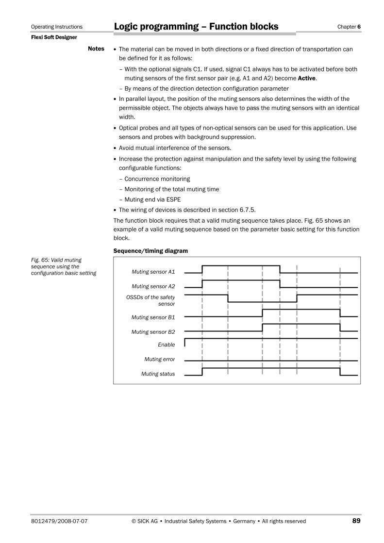
Operating Instructions Chapter 6
Flexi Soft Designer
8012479/2008-07-07 © SICK AG • Industrial Safety Systems • Germany • All rights reserved 89
Logic programming – Function blocks
The material can be moved in both directions or a fixed direction of transportation can be defined for it as follows:
– With the optional signals C1. If used, signal C1 always has to be activated before both muting sensors of the first sensor pair (e.g. A1 and A2) become Active.
– By means of the direction detection configuration parameter
In parallel layout, the position of the muting sensors also determines the width of the permissible object. The objects always have to pass the muting sensors with an identical width.
Optical probes and all types of non-optical sensors can be used for this application. Use sensors and probes with background suppression.
Avoid mutual interference of the sensors.
Increase the protection against manipulation and the safety level by using the following configurable functions:
– Concurrence monitoring
– Monitoring of the total muting time
– Muting end via ESPE
The wiring of devices is described in section 6.7.5.
The function block requires that a valid muting sequence takes place. Fig. 65 shows an example of a valid muting sequence based on the parameter basic setting for this function block.
Sequence/timing diagram
Notes
Fig. 65: Valid muting sequence using the configuration basic setting Muting sensor A1
Muting sensor A2
OSSDs of the safetysensor
Muting sensor B1
Muting sensor B2
Enable
Muting error
Muting status

Chapter 6 Operating instructions
Flexi Soft Designer
90 © SICK AG • Industrial Safety Systems • Germany • All rights reserved 8012479/2008-07-07
Logic programming – Function blocks
6.7.9 Muting with sequential layout of sensor pairs
Function block diagram
Representation of the application
Fig. 67 shows an example of the placement of sensors using the function block Muting with a sequential layout of sensor pairs.
In the example, the material moves from the left to the right. As soon as the muting sensors A1 & A2 are activated, the protective effect of the protective device (ESPE) is muted. The protective effect remains muted until a sensor of the muting sensor pair B1 & B2 becomes free again.
Input conditions for muting sensors
Condition Description
A1 & A2 (or B1 & B2)
Starts the muting cycle. The first sensor pair is activated depending on the direction of transportation of the material.
A1 & A2 & B2 & B1 Condition for transferring the muting function to the second sensor pair.
B1 & B2 (or A1 & A2)
Muting applies as long as this condition is fulfilled. The second sensor pair is activated depending on the direction of transportation of the material.
Fig. 66: Logic connections for the function block Muting with sequential layout of sensor pairs with Reset
Fig. 67: Example of the sequential layout of muting sensors
Table 70: Conditions for muting with four sensors in sequential layout
Transported material
ESPE (e.g. safety light curtain)
L2
L1
L3
Hazardous area
A1 A2 B1 B2

Operating Instructions Chapter 6
Flexi Soft Designer
8012479/2008-07-07 © SICK AG • Industrial Safety Systems • Germany • All rights reserved 91
Logic programming – Function blocks
Equations and prerequisites for calculating the distance:
L1 ≥ v × 2 × TIN Muting sensor
v × t > L1 + L3
L2 < L3
TIN Light curtain < TIN Muting sensor
Where ...
L1 = Distance between the inner sensors (layout symmetrical to the detection area of the ESPE)
L2 = Distance between the outer sensors (layout symmetrical to the detection area of the ESPE)
L3 = Length of the material in conveyor direction
v = Velocity of the material (e.g. of the conveyor belt)
t = Set total muting time [s]
In this example the material can either be moved in both directions or a fixed direction of transportation can be defined as follows:
– With the optional signal C1. If used, signal C1 always has to be activated before both muting sensors of the first sensor pair (e.g. A1 and A2) become Active.
– By means of the direction detection configuration parameter
The sensor layout shown in this example is suitable for all types of sensors.
Avoid mutual interference of the sensors.
Increase the protection against manipulation and the safety level by using the following configurable functions:
– Concurrence monitoring
– Monitoring of the total muting time
– Muting end via ESPE
– Sequence monitoring
The wiring of devices is described in section 6.7.5.
Notes

Chapter 6 Operating instructions
Flexi Soft Designer
92 © SICK AG • Industrial Safety Systems • Germany • All rights reserved 8012479/2008-07-07
Logic programming – Function blocks
Sequence/timing diagram
The function block requires that a valid muting sequence takes place. Fig. 68 shows an example of a valid muting sequence based on the parameter basic setting for this function block.
6.7.10 Function block 2-sensor muting (with crossed sensors) – Direction of movement only forwards or backwards
Function block diagram
Fig. 68: Valid muting sequence using the configuration basic setting
Fig. 69: Logic connections for the function block 2-sensor muting with resetting
Muting sensor A1
Muting sensor A2
OSSDs of the safety sensor
Muting sensor B1
Muting sensor B2
Enable
Muting error
Muting status

Operating Instructions Chapter 6
Flexi Soft Designer
8012479/2008-07-07 © SICK AG • Industrial Safety Systems • Germany • All rights reserved 93
Logic programming – Function blocks
Representation of the application
Fig. 70 shows an example of the sensor layout for the function block 2-sensor muting. The optional signal C1 is used as an additional protection for the muting system against manipulation.
The protective effect of the protective device is muted when the muting sensors are operated in a defined sequence. The muting sensor (signal C1) always has to be activated before both muting sensors of the first sensor pair (e.g. A1 and A2) become Active.
Input conditions for muting sensors
Condition Description
C1 & A1 & A2 Signal C1 always has to be activated before both muting sensors of the first sensor pair (e.g. A1 and A2) become Active.
A1 & A2 Muting applies as long as this condition is fulfilled and the requirement mentioned above existed.
Equations and prerequisites for calculating the distance:
L1 ≥ v × TIN Muting sensor
v × t > L2 + L3
L3 > L4
TIN Light curtain < TIN Muting sensor
Where ...
L1 = Minimum distance between the detection line of the ESPE and the detection by A1, A2
L2 = Distance between the two detection lines of the sensors (sensors activated/sensors free)
L3 = Length of material in conveyor direction
L4 = Maximum distance between C1 and the detection line of A1, A2
v = Velocity of the material (e.g. of the conveyor belt)
t = Set total muting time [s]
Fig. 70: Example of 2-sensor muting (with crossed layout sensors) and the optional signal C1
Table 71: Conditions for muting with two sensors and optional signal C1, crossed layout of the sensors
Transported material C1
Hazardous area
A1
A2
ESPE (e.g. safety light curtain) L3 L4
L1
L2

Chapter 6 Operating instructions
Flexi Soft Designer
94 © SICK AG • Industrial Safety Systems • Germany • All rights reserved 8012479/2008-07-07
Logic programming – Function blocks
Material flow is only possible in one direction in this example.
In order to move material in both directions (i.e. bidirectionally), place the intersection directly in the light beams of the ESPE (see section 6.7.11 "Function block 2-sensor muting (with crossed sensors) – Material transport in both directions" on page 94).
The sensor layout shown in this example is suitable for both through-beam photoelectric switches and photoelectric reflex switches.
Avoid mutual interference of the sensors.
Increase the protection against manipulation and the safety level by using the following configurable functions:
– Concurrence monitoring
– Monitoring of the total muting time
– Muting end via ESPE
The wiring of devices is described in section 6.7.5.
Sequence/timing diagram
The function block requires that a valid muting sequence takes place. Fig. 71 shows an example of a valid muting sequence based on the parameter basic setting for this function block. The optional signal C1 is not contained in the sequence shown below.
6.7.11 Function block 2-sensor muting (with crossed sensors) – Material transport in both directions
Function block diagram
Notes
Fig. 71: Valid muting sequence using the configuration basic setting
Fig. 72: Logic connections for the function block 2-sensor muting (with crossed sensors) with Reset
Muting sensor A1
Muting sensor A2
OSSDs of the safetysensor
Enable
Muting error
Muting status

Operating Instructions Chapter 6
Flexi Soft Designer
8012479/2008-07-07 © SICK AG • Industrial Safety Systems • Germany • All rights reserved 95
Logic programming – Function blocks
Representation of the application
The sensors can be located as follows in the case of muting applications with 2 crossed sensors in which the material has to be moved in both directions. The optional signal C1 is not used in this application example.
Ensure that the muting sensors detect only the moved material!
Ensure that the muting sensors are positioned in such a manner that no one can enter the hazardous area by fulfilling the muting conditions (meaning that they activate both muting sensors and thus create the required conditions for muting).
Input conditions for muting sensors
Condition Description
A1 & A2 Muting applies as long as this condition is fulfilled and, furthermore, the requirements mentioned above existed.
Equations and prerequisites for calculating the distance:
L1 ≥ v × TIN Muting sensor
v × t > L2 + L3
TIN Light curtain < TIN Muting sensor
Where ...
L1 = Minimum distance between the detection line of the ESPE and the detection by A1, A2
L2 = Distance between the two detection lines of the sensors (sensors activated/sensors free)
L3 = Length of material in conveyor direction
v = Velocity of the material (e.g. of the conveyor belt)
t = Set total muting time [s]
ATTENTION
Fig. 73: 2-sensor muting (with crossed sensors) for bidirectional movement of material
Table 72: Conditions for muting with two sensors and optional signal C1, crossed layout of the sensors
Transported material
ESPE (e.g. safety light curtain)
A1
A2 L3
L2
L1
Hazardous area

Chapter 6 Operating instructions
Flexi Soft Designer
96 © SICK AG • Industrial Safety Systems • Germany • All rights reserved 8012479/2008-07-07
Logic programming – Function blocks
Material flow is possible in both directions in this example.
In order for materials to be moved in both directions, place the intersection of the muting sensors exactly in the course of the light beams of the ESPE.
In order to move material in one direction only, place the intersection, with regard to the direction of the transport, behind the light beams of the ESPE (see section 6.7.10 "Function block 2-sensor muting (with crossed sensors) – Direction of movement only forwards or backwards" on page 92).
The sensor layout shown in this example is suitable for both through-beam photoelectric switches and photoelectric reflex switches.
Avoid mutual interference of the sensors.
Increase the protection against manipulation and the safety level by using the following configurable functions:
– Concurrence monitoring
– Monitoring of the total muting time
– Muting end via ESPE
The wiring of devices is described in section 6.7.5.
Sequence/timing diagram
The function block requires that a valid muting sequence takes place. Fig. 74 shows an example of a valid muting sequence based on the parameter basic setting for this function block.
Notes
Fig. 74: Valid muting sequence using the configuration basic setting Muting sensor A1
Muting sensor A2
OSSDs of the safetysensor
Enable
Muting error
Muting status

Operating Instructions Chapter 6
Flexi Soft Designer
8012479/2008-07-07 © SICK AG • Industrial Safety Systems • Germany • All rights reserved 97
Logic programming – Function blocks
6.8 Function blocks for press applications
6.8.1 Function block Eccentric press contact
Function block diagram
General description
The function block Eccentric press contact is used to monitor the cam input signals of mechanical or eccentric presses.
If no error was detected, the Enable signal of the function block Eccentric press contact is Active (High). Normally the Enable signal of this function block is connected to the next press element (e.g. function block Press set-up or function block Press single stroke).
The Enable signal of the subsequent function block (e.g. function block Press set-up or function block Press single stroke) is then used both for actuator control and as a feedback for the control input of this function block.
The minimum configuration requires an Overrun cam and the Run-up cam. Optionally, a Dynamic cam input can also be connected.
The function block Eccentric press contact monitors the Overrun cam and the correct cam signal sequence of presses. If any discrepancy is detected, Enable changes to Inactive (Low) and the corresponding error output changes to Active.
Parameters of the function block
Parameter Possible parameter values: Configuration basic setting
Dynamic cam With
Without
With
Minimum duration for restart pulse
100 ms
350 ms
350 ms
Ensure that the transitions of the signals for restarting fulfil the requirements of the safety standards and regulations!
In case of a short-circuit to High (to 24 V DC) at a physical input, the evaluated signal can have a pulse when the signal is reset due to the short-circuit detection. If such a pulse can result in a hazardous state in the machine, the following points have to be observed:
Ensure protected cable laying for the signal line (due to cross-circuiting to other signal lines)
No short-circuit detection, i.e. do not reference to test outputs.
Fig. 75: Logic connections for the function block Eccentric press contact
Table 73: Parameters of the function block Eccentric press contact
ATTENTION

Chapter 6 Operating instructions
Flexi Soft Designer
98 © SICK AG • Industrial Safety Systems • Germany • All rights reserved 8012479/2008-07-07
Logic programming – Function blocks
Input parameters of the function block
The function block Eccentric press contact supports the following input parameters
Control input
Restart input
Overrun cam
Run-up cam
Dynamic cam
Depending on your risk analysis and avoidance strategy, the inputs for each of these signals can be evaluated as single-channel or dual-channel.
The Run-up cam signals have to conform to your risk analysis!
If a single-channel signal (with or without testing) is used for the Run-up cam, an error can cause an Active (High) signal. You can avoid this by using two Overrun cam signals and evaluating these as a dual-channel input (with discrepancy time monitoring). If you use this signal, take the standards and regulations to be applied into consideration in accordance with your risk analysis and avoidance strategy.
A different test pulse signal has to be used for each monitored input.
The input signals for the Overrun cam, Run-up cam and Dynamic cam have to accord with Fig. 76.
Overrun cam
The signal of the Overrun cam allows the function block to monitor the overrunning of the press. When the press reaches the top dead centre (indicated by the transition of the Overrun cam signal to Active (High)), the corresponding Top output signal stops the press. An overrun error occurs when the press has not started again (i.e. the control input remains Inactive (Low)) and the Overrun cam changes from Active (High) to Inactive (Low) (i.e. falling edge). An overrun error can only be reset by a valid restart sequence.
ATTENTION
Fig. 76: Press cycle diagram for the function block Eccentric press contact
Run-up cam
Overrun cam
Dynamic cam
270° 90°
0°
180°

Operating Instructions Chapter 6
Flexi Soft Designer
8012479/2008-07-07 © SICK AG • Industrial Safety Systems • Germany • All rights reserved 99
Logic programming – Function blocks
Run-up cam
The rising edge of the Run-up cam input indicates the beginning of the Run-up part of the press cycle. This Up signal ends with a rising edge (i.e. the transition of the Overrun cam from Inactive (Low) to Active (High)).
For safety reasons, there must not be a Run-up signal, in case the press starts, while the Run-up cam is Active (High) (e.g. in the first cycle after switching on or after an error). The second cycle begins when the Overrun cam changes from Active (High) to Inactive (Low).
Dynamic cam
Dynamic cam is an optional input signal that determines how the output signals for the press cycle are determined. The input signal for Dynamic cam can both change its state several times as well as not at all during a single press cycle.
If Dynamic cam changes from Active (High) to Inactive (Low) (i.e. falling edge), the Top output becomes Active (High) and the Run-up output becomes Inactive (Low). The Top output remains Active (High) until Overrun cam changes from Active (High) to Inactive (Low). If this happens, the Top output becomes Inactive (Low). This means that a second transition of Dynamic cam from Active (High) to Inactive (Low) does not have any influence of the signal state of the Top output.
Output parameters of the function block
Top dead centre
If this function block is configured without Dynamic cam, the Top output signal is based on the Overrun cam input signal. Fig. 77 shows a logic diagram for the Top output.
If this function block is configured with an input for Dynamic cam and Dynamic cam changes from Active (High) to Inactive (Low) (i.e. falling edge), the Top output changes to Active (High). The Top dead centre output remains Active (High) until Overrun cam changes from Active (High) to Inactive (Low). When this happens the Top output becomes Inactive (Low). This means that a second transition of Dynamic cam from Active (High) to Inactive (Low) does not have any influence of the signal state of the Top output.
Fig. 77: Sequence/timing diagram for Top output with Dynamic cam
Fig. 78: Sequence/timing diagram for Top dead centre output without Dynamic cam
Overrun cam
Run-up cam
Top output
Overrun cam
Run-up cam
Top dead centre output
Dynamic cam

Chapter 6 Operating instructions
Flexi Soft Designer
100 © SICK AG • Industrial Safety Systems • Germany • All rights reserved 8012479/2008-07-07
Logic programming – Function blocks
Run-up output
The rising edge of the Run-up cam input indicates the beginning of the Run-up part of the press cycle. This Run-up signal ends with a rising edge (i.e. the transition from Inactive (Low) to Active (High) of the Overrun cam).
For safety reasons, there must not be a Run-up signal, in case the press starts, while the Run-up cam is Active (High) (e.g. in the first cycle after switching on or after an error). The second cycle begins when the Overrun cam changes from Active (High) to Inactive (Low).
The muting cycle is terminated when Dynamic cam changes from Active (High) to Inactive (Low). This is indicated by the transition of Run-up to Inactive (Low).
Error outputs
The following additional error outputs are available:
Optional output connections of the function block
Contact error
Overrun error
Fault present
Fig. 79: Sequence/timing diagram for Run-up output without Dynamic cam
Fig. 80: Sequence/timing diagram for Run-up output with Dynamic cam
Notes
Table 74: Error outputs for the function block Eccentric press contact
Overrun cam
Run-up cam
Run-up output
Overrun cam
Run-up cam
Run-up output
Dynamic cam

Operating Instructions Chapter 6
Flexi Soft Designer
8012479/2008-07-07 © SICK AG • Industrial Safety Systems • Germany • All rights reserved 101
Logic programming – Function blocks
Contact error output
Several conditions apply for the Overrun cam and Run-up cam input signals. These are:
When Overrun cam changes from Inactive (Low) to Active (High), Run-up cam has to be Active (High) or just have changed to Inactive (Low) during the current cycle.
When Overrun cam changes from Active (High) to Inactive (Low), Run-up cam has to be Inactive (Low).
When Run-up cam changes from Inactive (Low) to Active (High), Overrun cam has to be Inactive (Low).
When Run-up cam changes from Active (High) to Inactive (Low), Overrun cam has to be Active (High).
If one of the above-mentioned conditions is not fulfilled during operation, Enable becomes Inactive (Low; fail-safe) and the Contact error output becomes Active (High). Enable cannot be reset until a valid restart sequence has taken place (i.e. transition from Inactive (Low) to Active (High; at least 100 ms or 350 ms, maximum 30 s) to Inactive (Low)).
Overrun error output
When Overrun cam changes from Active (High) to Inactive (Low), the function block Eccentric press contact checks whether the control input signal is Active (High). If the control input signal is Inactive (Low), there is an overrun error.
Fig. 81: Example of a sequence/timing diagram for Overrun errors without Dynamic cam
Fig. 82: Example of a sequence/timing diagram for Overrun errors with Dynamic cam
Overrun cam
Control input
Overrun error
Enable
Overrun cam
Dynamic cam
Enable
Control input
Overrun error

Chapter 6 Operating instructions
Flexi Soft Designer
102 © SICK AG • Industrial Safety Systems • Germany • All rights reserved 8012479/2008-07-07
Logic programming – Function blocks
Error states and information on restarting
Diagnostics outputs
Fault present
Resetting the error state Remarks
Contact error
Overrun error
Active When Contact error or Overrun error are Active, the Restart request output is Active. A valid restart sequence sets the error state (i.e. contact error or overrun error) to Inactive.
Enable changes to Inactive and the fault present changes to Active, if either Contact error or Overrun error is Active.
Safety-relevant signals have to conform to standards and regulations to be applied!
Always take the valid national, regional and local regulations and standards into consideration for your application. Type-C standards such as EN 692 and EN 693 contain requirements how safety-relevant signals have to be used. For example, the restart signal has to be protected by suitable means in case of overrun errors (e.g. by a key switch or in a closed control cabinet).
6.8.2 Universal press contact
Function block diagram
General description
The function block Universal press contact is used to monitor press contacts of different press types (e.g. hydraulic presses and eccentric presses (i.e. mechanical presses)).
If no errors were detected, the Enable signal of the function block Universal press contact is Active (High). Normally, the Enable signal of this function block is connected to the next press element (e.g. Function block Press set-up or Function block Press single stroke).
The Enable signal of the subsequent function block (e.g. function block Press set-up or function block Press single stroke) is then used both for actuator control and as a feedback for the control input of this function block.
The minimum configuration requires only Top dead centre. Optionally, the Bottom dead centre and Overrun contact inputs can be connected. If Bottom dead centre is not used, the Run-up output is not available.
This function block monitors the overrunning of the press and the correct sequence of Top dead centre, Bottom dead centre and Overrun contact. If any discrepancy is detected, Enable changes to Inactive (Low) and the corresponding error output changes to Active.
If Bottom dead centre and Overrun contact are not used, a plausibility check is not possible for the function block. In this case, a check for overrunning cannot be carried out. The only remaining function in this case is the provision of the Top dead centre signal.
Table 75: Error states and information on restarting for the function block Eccentric press contact
ATTENTION
Fig. 83: Logic connections for the function block Universal press contact

Operating Instructions Chapter 6
Flexi Soft Designer
8012479/2008-07-07 © SICK AG • Industrial Safety Systems • Germany • All rights reserved 103
Logic programming – Function blocks
Parameters of the function block
Parameter Possible parameter values: Configuration basic setting
Bottom dead centre With
Without
With
Overrun contact With
Without
With
Number of Bottom dead centre signals per press cycle
1 (e.g. eccentric press)
0 … 2 (e.g. hydraulic press)
1 (e.g. eccentric press)
Min. restart pulse time (minimum duration for restart pulse)
100 ms
350 ms
350 ms
If the number of Bottom dead centre signals per press cycle is set to 0 to 2 (e.g. hydraulic press), it may not be possible to detect certain errors such as a short-circuit to Low (i.e. short-circuit to 0 V DC) or an Inactive (Low) signal that was caused by an error detected at the Bottom dead centre input signal.
Ensure that the transitions of the signals for restarting fulfil the requirements of the safety standards and regulations!
In case of a short-circuit to High (to 24 V DC) at a physical input, the evaluated signal can have a pulse when the signal is reset due to the short-circuit detection. If such a pulse can result in a hazardous state in the machine, the following points have to be observed:
Ensure protected cable laying for the signal line (due to cross-circuiting to other signal lines)
No short-circuit detection, i.e. do not reference to test outputs.
Input signals of the function block
The function block Universal press contact supports the following input parameters:
Control input
Restart input
Top dead centre
Bottom dead centre
Overrun contact
The input signals for Top dead centre, Bottom dead centre and Overrun contact have to use separate test pulse outputs and accord with Fig. 84 below. Depending on your risk analysis and avoidance strategy and the standards and regulations to be applied (e.g. EN 692 or EN 693) the Top dead centre, Bottom dead centre and Overrun contact inputs can be evaluated using single-channel or dual-channel configurations.
Table 76: Parameters of the function block Universal press contact
Notes
ATTENTION

Chapter 6 Operating instructions
Flexi Soft Designer
104 © SICK AG • Industrial Safety Systems • Germany • All rights reserved 8012479/2008-07-07
Logic programming – Function blocks
The Bottom dead centre signals have to conform to your risk analysis!
If a single-channel signal (with or without testing) is used for Bottom dead centre, an error can cause an Active (High) signal. You can avoid this by using two Bottom dead centre signals and evaluating these as a dual-channel input (with discrepancy time monitoring). If the number of Bottom dead centre signals per press cycle was configured to 0 … 2, two Bottom dead centre signals have to be used. If you use this signal, take the applicable standards and regulations into consideration in accordance with your risk analysis and avoidance strategy.
For a complete cycle of 360°, the following conditions apply for the Top dead centre, Bottom dead centre and Overrun contact signals:
Top dead centre (middle ring) has to be triggered at or near 0°. Top dead centre has to be Inactive (Low) in the filled section of the middle ring. During the remaining period of the press cycle, Top dead centre is Active (High). Only one Inactive (Low) signal is permissible for Top dead centre per press cycle.
The signal for Bottom dead centre (innermost ring) should be triggered at or near 180°. The filled section of the innermost ring shows the ideal Bottom dead centre signal. The hatched section shows other possible values for Bottom dead centre. Bottom dead centre is Active (High) in the filled and in the dark hatched section of the innermost ring. The bright hatched section is only permissible if all three contacts (Top dead centre, Bottom dead centre and Overrun contact) are used. Bottom dead centre should be Inactive (Low) during the remaining press cycle. The rising edge (i.e. the transition from Inactive (Low) to Active (High)) may not be effected before the falling edge (i.e. the transition from Active (High) to Inactive (Low)) of the Overrun contact has occurred in the preceding press cycle.
ATTENTION
Fig. 84: Press cycle diagram for the function block Universal press contact
Top dead centre(Inactive)
Bottom dead centre (Active)
Overrun contact(Active)
0°
180°
270° 90°

Operating Instructions Chapter 6
Flexi Soft Designer
8012479/2008-07-07 © SICK AG • Industrial Safety Systems • Germany • All rights reserved 105
Logic programming – Function blocks
The falling edge (i.e. the transition from Active (High) to Inactive (Low)) of Bottom dead centre has to occur under one of the following conditions:
– Before or while the Top dead centre signal changes to Inactive (Low), if the Overrun contact is configured as not used, or
– Before, during or after the Top dead centre signal changes to Inactive (Low), but before the falling edge (i.e. transition from Inactive (Low) to Active (High)) of the Overrun contact signal, if the latter is configured as used.
The rising edge (i.e. transition from Inactive (Low) to Active (High)) of the Overrun contact (outermost ring) has to occur before the Top dead centre becomes Inactive (Low). The falling edge (i.e. the transition from Active (High) to Inactive (Low)) has to occur after the Top dead centre signal has changed to Active (High). The filled section of the outermost ring shows the ideal Overrun contact signal. The hatched section shows other possible values for the Overrun contact. The Overrun contact is Active (High) in the filled and hatched section of the outermost ring. The Overrun contact should be Inactive (Low) during the remaining press cycle. Only one Active (High) signal is permissible for the Overrun contact per press cycle.
If one of the above-mentioned conditions is not fulfilled correctly during operation, Enable becomes Inactive (Low; fail-safe) and the Contact error output becomes Active (High). A valid restart sequence is necessary before Enable can return to Active (High).
Function block outputs
The following table describes the outputs that can be available depending on the configured input signals.
Outputs Contacts
Enable Top Run-up Reset request
Contact error
Overrun error
Top dead centre
Top dead centre + Overrun contact
Top dead centre + Bottom dead centre
Top dead centre + Overrun contact + Bottom dead centre
Table 77: Possible output signals for the function block Universal press contact

Chapter 6 Operating instructions
Flexi Soft Designer
106 © SICK AG • Industrial Safety Systems • Germany • All rights reserved 8012479/2008-07-07
Logic programming – Function blocks
Top output
The signal of the Top output is Active (High), when the Top dead centre signal is Active (High). Bottom dead centre and Overflow contact do not have any effect on the Top output signal. Fig. 85 shows a logic diagram for the Top output.
Run-up output
If Bottom dead centre is configured and used, it acts directly on the Run-up output. This output signal can be used in combination with other function blocks, e.g. for Upstroke muting. If Bottom dead centre is Active (High) during the system start-up, the Run-up output remains Inactive (Low) until the Bottom dead centre returns to Inactive (Low) and afterwards changes to Active (High). The following situations are possible:
Error outputs
The following additional error outputs are available:
Optional output connections of the function block
Contact error
Overrun error
Fault present
Fig. 85: Top signal
Fig. 86: Run-up output when Top dead centre and Bottom dead centre do not superimpose
Fig. 87: Run-up output when Top dead centre and Bottom dead centre superimpose
Fig. 88: Run-up output at two Bottom dead centre signals per press cycle
Table 78: Error outputs of the function block Universal press contact
Top dead centre
Bottom dead centre
Top output
Top dead centre
Bottom dead centre
Run-up output
Top dead centre
Bottom dead centre
Run-up output
Top dead centre
Bottom dead centre
Run-up output

Operating Instructions Chapter 6
Flexi Soft Designer
8012479/2008-07-07 © SICK AG • Industrial Safety Systems • Germany • All rights reserved 107
Logic programming – Function blocks
Contact error output
Several conditions apply for the use of the Top dead centre, Bottom dead centre and Overrun contact signal inputs. These are:
If Bottom dead centre is used and the number of the Bottom dead centre signals per press cycle is set to 1, one Bottom dead centre per cycle is required.
If Overrun contact is set to "Without", the falling edge has to occur at the Bottom dead centre (i.e. a transition from Active (High) to Inactive (Low)), before Top dead centre changes from Inactive (Low) to Active (High).
If Overrun contact is set to "With", the Bottom dead centre signal may become Inactive (Low) after the Top dead centre has changed from Inactive (Low) to Active (High). However, it has to change from Active (High) to Inactive (Low) before the Overrun contact changes from Active (High) to Inactive (Low).
Only one Top dead centre signal is allowed per press cycle (this can only be detected if Bottom dead centre and Overrun contact are also used).
If it is used, only one Overrun contact signal per cycle is allowed.
The rising edge (i.e. the transition from Inactive (Low) to Active (High)) at the Bottom dead centre may not occur before the falling edge (i.e. the transition from Active (High) to Inactive (Low)) of the Overrun contact of the preceding cycle.
The rising edge (i.e. Inactive (Low) to Active (High)) of the Overrun contact has to occur before the Top dead centre signal changes from Inactive (Low) to Active (High).
The falling edge (i.e. Active (High) to Inactive (Low)) of the Overrun contact has to occur after the Top dead centre signal has changed from Inactive (Low) to Active (High).
If one of the above-mentioned conditions is not fulfilled during operation, Enable becomes Inactive (Low, fail-safe) and the Contact error output becomes Active (High). Enable cannot be reset until after a valid restart sequence has taken place (i.e. transition from Inactive (Low) to Active (High; > 100 ms or 350 ms, < 30 s) to Inactive (Low)).
Overrun error output
If the Overrun contact input is defined and used, the function block monitors the overrunning of the press. If the Overflow contact input changes from Active (High) to Inactive (Low) and the control input remains Inactive (Low) (i.e. the press has not started), there is an overrun error and the Overrun error output becomes Active (High).
Fig. 89: Example of a sequence/timing diagram for Overrun error Top dead centre
Overrun contact
Control input
Enable
Overrun error

Chapter 6 Operating instructions
Flexi Soft Designer
108 © SICK AG • Industrial Safety Systems • Germany • All rights reserved 8012479/2008-07-07
Logic programming – Function blocks
Error states and information on restarting
Diagnostics outputs
Fault present
Resetting the error state Remarks
Contact error
Overrun error
Active When Contact errors or Overrun errors are Active, the Restart request output is Active (pulsing with 1 Hz). A valid restart sequence sets the error state (i.e. Contact error or Overrun error) to Inactive.
Enable changes to Inactive and the fault present changes to Active, if either the Contact error or Overrun error is Active.
Safety-relevant signals have to conform to the applicable standards and regulations to be applied!
Always take the valid national, regional and local regulations and standards into consideration for your application. Type-C standards such as EN 692 and EN 693 contain requirements how safety-relevant signals have to be used. For example, the restart signal has to be protected by suitable means in case of overrun errors (e.g. by a key switch or in a closed control cabinet).
6.8.3 Function block Press set-up
Function block diagram
General description
The function block Press set-up is generally used together with the function block Universal press contact or the function block Eccentric press contact in order to set up the press and in order to provide the information of the Top output as input for this function block. The Top output is required for single-stroke operation. Control of the press can, for example, be effected by means of a two-hand control.
Table 79: Error states and information on restarting for the function block Universal press contact
ATTENTION
Fig. 90: Logic connections for the function block Press set-up

Operating Instructions Chapter 6
Flexi Soft Designer
8012479/2008-07-07 © SICK AG • Industrial Safety Systems • Germany • All rights reserved 109
Logic programming – Function blocks
Parameters of the function block
Parameter Possible parameter values: Configuration basic setting
Restart interlock Without
When ON/START or EN1 Inactive
When Top output active or EN1 Inactive
Always
Always
EN2 static With
Without
With
Single-stroke securing With
Without
With
Min. restart pulse time (minimum duration for restart pulse)
100 ms
350 ms
350 ms
Ensure that the transitions of the signals for restarting fulfil the requirements!
In case of a short-circuit to High (to 24 V DC) at a physical input, the evaluated signal can have a pulse when the signal is reset due to the short-circuit detection. If such a pulse can result in a hazardous state in the machine, the following points have to be observed:
Protected cable laying for the signal line (due to cross-circuiting to other signal lines)
No short-circuit detection, i.e. do not reference to test outputs.
Input signals of the function block
The function block Press set-up supports the following input signals:
ON/START
The ON/START input signal is used to indicate the beginning and the end of the press movement. A rising edge (i.e. transition from Inactive (Low) to Active (High)) at the ON/START input signals a start of the press. An Inactive (Low) ON/START input signals a stop of the press. If Restart interlock is set to "When ON/START or EN1 Inactive", a valid restart sequence is required after a stop that was caused by an Inactive (Low) ON/START input signal.
EN1 static
The input signal EN1 static is mandatory. Enable always changes immediately to Inactive (Low), if EN1 static is Inactive (Low).
If this function block is used together with a press contact function block (e.g. Eccentric Press Contact or Universal Press Contact), its enable signal must be connected with the EN1 static input of this function block.
EN2 start
The input signal EN2 start is optional. If EN2 start is configured, Enable can only change to Active (High) (e.g. during switching on), if EN2 start is Active (High). If Enable is Active (High), EN2 start is no longer monitored.
Table 80: Parameters of the function block Press set-up
ATTENTION

Chapter 6 Operating instructions
Flexi Soft Designer
110 © SICK AG • Industrial Safety Systems • Germany • All rights reserved 8012479/2008-07-07
Logic programming – Function blocks
Top
The Top input signal is used in order to determine the end of the press cycle (i.e. the press has reached the top dead centres. This input signal is available at the function blocks Eccentric press contact or Universal press contact. The Top input signal is used for single-stroke securing. When the Single-stroke securing configuration parameter is set to "Yes", Enable changes to Inactive (Low) when the Top input signal changes from Inactive (Low) to Active (High).
Restart input
If the Restart interlock configuration parameter has been set to "Without", a Restart signal is not required in order to restart the press after any kind of stop. The Restart interlock parameter can also be set to the following values:
When ON/START or EN1 Inactive
When Top output Active or EN1 Inactive
Always
This parameter determines when a Restart interlock signal is expected as input signal for the function block. The Restart signal itself should be realised using a separate function block Restart in order to ensure that a valid restart sequence occurs.
If Enable changes to Inactive (Low) because of the above-mentioned settings of the configuration parameters for Restart interlock, Enable can only be reset after a valid restart sequence has been carried out (i.e. the Restart input changes from Inactive (Low) to Active (High; 100 ms or 350 ms < 30 s) and back to Inactive (Low)).
Output signals of the function block
Restart required
The Restart required output is Active, when a valid restart sequence is expected at the Restart input.
Enable
Enable is Active (High), when Restart request is Inactive (Low) (i.e. restart is not required) and the following conditions are fulfilled:
When Single-stroke securing is set to "Without", EN1 static is Active (High) and EN2 start (if necessary) is Active (High); and a rising edge (i.e. transition from Inactive (Low) to Active (High)) is detected at the ON/START input; or
If Single-stroke securing is set to "With", ON/START changes from Inactive (Low) to Active (High), EN1 static is Active (High) and EN2 start (if necessary) is Active (High). In this case Enable changes to Inactive (Low) when the Top input signal changes from Inactive (Low) to Active (High).

Operating Instructions Chapter 6
Flexi Soft Designer
8012479/2008-07-07 © SICK AG • Industrial Safety Systems • Germany • All rights reserved 111
Logic programming – Function blocks
Error conditions
The function block Press set-up does not carry out monitoring for error conditions.
6.8.4 Function block Press single stroke
Function block diagram
General description
The function block Press single stroke is generally used together with the function block Universal press contact or the function block Eccentric press contact in order to provide the information of the Top and Run-up outputs as input for this function block. The Top output is required for single-stroke operation. Controlling of the press can, for example, be implemented by means of a two-hand control or by means of a function block N-PSDI mode in connection with a safety light curtain.
Single-stroke securing is always Active and cannot be configured. This means: When the signal of the Top input changes to Active (High), Enable is always set to Inactive (Low). The requirements for a restart depend of the configuration of the parameters for Restart interlock.
Fig. 91: Sequence/timing diagram for the function block Press set-up
Fig. 92: Logic connections for the function block Press single stroke
ON/START
EN1 static
EN2 start
Top input
Enable
Enable remains active when Single-stroke securing is "No"

Chapter 6 Operating instructions
Flexi Soft Designer
112 © SICK AG • Industrial Safety Systems • Germany • All rights reserved 8012479/2008-07-07
Logic programming – Function blocks
Parameters of the function block
Parameter Possible parameter values: Configuration basic setting
Restart interlock Without When ON/START or EN1 Inactive or EN3 Inactive When Top output Active or EN1 Inactive or EN3 Inactive Always When EN1 Inactive or EN3 Inactive
Always
EN2 Enable condition fulfilled (static enable EN2)
With Without
With
Safety enable EN3 With Without
With
ON/START mode Stepping mode Only start
Stepping mode
Upstroke muting of ON/START
Yes No
No
Maximum upstroke muting time
Can be configured in the range of 0 to 7200 s (120 min). When the maximum upstroke muting time is set to 0, upstroke muting is not possible and nothing can be connected to the Run-up input.
30 s
Min. restart pulse time (minimum duration for restart pulse)
100 ms 350 ms
350 ms
Ensure that the transitions of the signals for restarting fulfil the requirements of the safety standards and regulations!
In case of a short-circuit to High (to 24 V DC) at a physical input, the evaluated signal can have a pulse when the signal is reset due to the short-circuit detection. If such a pulse can result in a hazardous state in the machine, the following points have to be observed:
Ensure protected cable laying for the signal line (due to cross-circuiting to other signal lines)
No short-circuit detection, i.e. do not reference to test outputs.
Input parameters and input signals of the function block
The function block Press single stroke supports the following input signals:
ON/START
The ON/START input signal is used to indicate the beginning and the end of the press movement. A rising edge (i.e. transition from Inactive (Low) to Active (High)) at the ON/START input signals a start of the press. An Inactive (Low) ON/START input signals a stop of the press. If the ON/START mode parameter is set to "Only start", the press cannot be stopped by the ON/START input signal.
Table 81: Parameters of the function block Press single stroke
ATTENTION

Operating Instructions Chapter 6
Flexi Soft Designer
8012479/2008-07-07 © SICK AG • Industrial Safety Systems • Germany • All rights reserved 113
Logic programming – Function blocks
If the ON/START mode parameter is set to "Stepping mode" and Restart interlock to "When ON/START or EN1 Inactive" or "Always", a valid restart sequence is required after a stop that was caused by an Inactive (Low) ON/START input signal.
The Enable signal of a two-hand control or of a function block N-PSDI mode is particularly suitable for connection to the ON/START input.
EN1 static
The input signal EN1 static is mandatory. Enable always changes immediately to Inactive (Low), if EN1 static is Inactive (Low).
If this function block is used together with a press contact function block (e.g. Eccentric press contact or Universal press contact), its Enable signal must be connected with the EN1 static input of this function block.
EN2 start
The input signal EN2 start is optional. If EN2 start is configured, Enable can only change to Active (High) (e.g. during switching on), if EN2 start is Active (High). If Enable is Active (High), EN2 start is no longer monitored.
Safety enable EN3
The Safety enable EN3 input signal is an optional signal that is available when Run-up is configured as used. Enable can only change from Inactive (Low) to Active (High) if EN3 Safety is Active (High) or if Run-up is Active (High). If Safety enable EN3 is Inactive (Low) and Run-up is Inactive (Low), Enable is set to Inactive (Low) and a restart sequence has to occur in accordance with the settings.
If Run-up is Active (High), the Safety enable EN3 signal is muted.
Upstroke muting of ON/START
If the maximum upstroke muting time is not set to 0, the Run-up input has to be connected. We advise using the Run-up output signal of a press contact function block (e.g. Eccentric press contact or Universal press contact).
In this case, the Safety enable EN3 and ON/START input signals are muted (muting of the ON/START input depends on the parameter settings) when the Run-up input is Active (High). This function block does not carry out a plausibility check of the Run-up input signal. If the Run-up input is Active (High) several times during a single press cycle, it is possible to mute the corresponding input of the function block several times. If a signal shall not be muted, it should be connected to the EN1 static input by means of an AND gate together with other signals that have to be connected to the EN1 static input.
Maximum upstroke muting time
The maximum upstroke muting time can be configured. This time begins with the rising edge of the signal at the Run-up input (i.e. the transition from Inactive (Low) to Active (High)). If the timer reaches the configured maximum upstroke muting time before a falling edge occurs at the Run-up input (i.e. a transition from Active (High) to Inactive (Low)), the function block interrupts the muting of the EN3 Safety and ON/START inputs. If at this moment one of these two inputs is Inactive (Low), Enable is also set to Inactive (Low).
The maximum upstroke muting time lies in the range of 0 to 120 minutes and is specified in seconds. If this parameter is set to "0", upstroke muting is deactivated.

Chapter 6 Operating instructions
Flexi Soft Designer
114 © SICK AG • Industrial Safety Systems • Germany • All rights reserved 8012479/2008-07-07
Logic programming – Function blocks
Restart input
If the Restart interlock configuration parameter has been set to "Without", a Restart signal is not required in order to restart the press after any kind of stop. The Restart interlock parameter can also be set to the following values:
When ON/START or EN1 Inactive or EN3 Inactive
When Top output Active or EN1 Inactive or EN3 Inactive
Always
When EN1 Inactive or EN3 Inactive
This parameter determines when a Restart interlock signal is expected as input signal for the function block. The Restart signal itself should be realised using a separate function block Restart in order to ensure that a valid restart sequence has occurred.
If Enable changes to Inactive (Low) because of the above-mentioned settings of the configuration parameters for Restart interlock, Enable can only be reset after a valid restart sequence has been carried out (i.e. the Restart input changes from Inactive (Low) to Active (High; 100 ms or 350 ms < 30 s) and back to Inactive (Low)).
Output signals of the function block
Restart request
The Restart request output is Active, when a valid restart sequence is expected at the Restart input.
Sequence/timing diagram for Enable
Fig. 93: Sequence/timing diagram for the function block Press single stroke when ON/START is configured in Stepping mode
Fig. 94: Sequence/timing diagram for the function block Press single stroke whenON/START is configured in Start only mode
Fig. 95: Sequence/timing diagram for the function block Press single stroke with upstroke muting of ON/START and Safety enable EN3
ON/START
Safety enable EN3
Top input
Run-up input
Enable
ON/START
Top input
Enable
ON/START
Top input
Enable
Upstroke muting

Operating Instructions Chapter 6
Flexi Soft Designer
8012479/2008-07-07 © SICK AG • Industrial Safety Systems • Germany • All rights reserved 115
Logic programming – Function blocks
Error conditions
The function block Press single stroke does not carry out monitoring for error conditions.
6.8.5 Function block Press automatic
Function block diagram
General description
The function block Press automatic is used in connection with press applications in which the workpieces are moved automatically to and from the press, but where a manual tool change is still required, for which, for example, a safety door has to be opened.
The function block can generate a stop signal for the press (i.e. Enable changes to Inactive (Low)) and enable the gate after a stop has been carried out in a position in which the tool can be changed easily (e.g. in the top position).
Parameters of the function block
Parameter Possible parameter values: Configuration basic setting
Restart interlock after stop has occurred
With
Without
With
Stop request With OFF/STOP Active
With ON/START Inactive
With OFF/STOP Active (High)
Run-up input With
Without
With
EN2 Enable condition fulfilled (static enable EN2)
With
Without
With
Minimum duration for restart pulse
100 ms
350 ms
350 ms
Ensure that the transitions of the signals for restarting fulfil the requirements of the safety standards and regulations!
In case of a short-circuit to High (to 24 V DC) at a physical input, the evaluated signal can have a pulse when the signal is reset due to the short-circuit detection. If such a pulse can result in a hazardous state in the machine, the following points have to be observed:
Ensure protected cable laying for the signal line (due to cross-circuiting to other signal lines)
No short-circuit detection, i.e. do not reference to test outputs.
Fig. 96: Logic connections for the function block Press automatic
Table 82: Parameters of the function block Press automatic
ATTENTION

Chapter 6 Operating instructions
Flexi Soft Designer
116 © SICK AG • Industrial Safety Systems • Germany • All rights reserved 8012479/2008-07-07
Logic programming – Function blocks
Input parameters and input signals of the function block
Stop at
The "Stop at" parameter determines the stop mode of the function block Press automatic. If this parameter is configured as "ON/START", the ON/START input signal is used to control the Enable signal directly. If configured to "OFF/STOP", Enable changes to Inactive (Low), when the OFF/STOP input signal is Active (High).
In both cases Enable changes to Active (High), when the following conditions are fulfilled:
A transition from Inactive (Low) to Active (High) occurs at the ON/START input; and
the OFF/STOP input is Inactive (Low), if it is connected; and
no other reason is present that would normally trigger a stop signal, e.g. EN1 START is Inactive (Low).
Run-up input
If the Run-up input parameter is configured as "With Run-up input", the connection of an Active (High) signal to this input allows the press to stop both during the downstroke and in the top position. If this parameter is set to "Without Run-up input", regular stops are only possible in the top position.
ON/START
The ON/START input signal is used to provide signals for the beginning and end of the press movement. If a rising edge (i.e. a transition from Inactive (Low) to Active (High)) is detected at the ON/START input, Enable becomes Active (High), provided that the OFF/STOP input is Inactive (Low) and no other reason is present that would normally trigger a stop signal, e.g. EN1 START is Inactive (Low). A valid restart sequence can be required before a signal transition of ON/START if the "With/Without restart interlock after stop" parameter is set to "Yes". If you connect a command device (e.g. a two-hand control) to the ON/START input, you must ensure that unintentional restarting is not possible.
OFF/STOP
If the "Stop at" parameter at OFF/STOP is set to Active, the OFF/STOP input signal is used to signal a stop to the press. When the OFF/STOP input is Active (High), Enable is set to Inactive (Low).
This input should only be used if the "Stop at" parameter has been set to OFF/STOP Active. The OFF/STOP input is not used when the "Stop at" parameter has been set to ON/START Inactive. A valid restart sequence can be required before a signal transition of ON/START when the "With/Without restart interlock after stop" parameter is set to "Yes". The OFF/STOP input is designed for the connection of signals that are not safety-relevant (e.g. from a programmable logic controller (PLC)). Safety-relevant signals may only be connected to the EN1 static input, not to the OFF/STOP input.
EN1 static
The input signal EN1 static is mandatory. Enable always changes immediately to Inactive (Low), if EN1 static is Inactive (Low).
If this function block is used together with a press contact function block (e.g. Eccentric press contact or Universal press contact), its enable signal must be connected with the EN1 static input of this function block.

Operating Instructions Chapter 6
Flexi Soft Designer
8012479/2008-07-07 © SICK AG • Industrial Safety Systems • Germany • All rights reserved 117
Logic programming – Function blocks
EN2 start
The input signal EN2 start is optional. When EN2 start is configured, Enable can only change to Active (High) (e.g. during switching on), when EN2 start is Active (High). When Enable is Active (High), EN2 start is no longer monitored.
Restart input
If the Restart interlock configuration parameter has been set to "No", a Restart signal is not required in order to restart the press after any kind of stop.
If the Restart interlock has been set to "Yes" and Enable changes to Inactive (Low), Enable can only be reset after a valid restart sequence has been carried out (i.e. the Restart input changes from Inactive (Low) to Active (high; > 100 ms or 350 ms < 30 s) and back to Inactive (Low)).
Output signals of the function block
Restart required
The Restart required output is Active, when a valid restart sequence is expected at the Restart input.
Sequence/timing diagram for Enable
Error conditions
The function block Press automatic does not carry out monitoring for error conditions.
6.8.6 Function block Press with N-PSDI mode
Function block diagram
Fig. 97: Sequence/timing diagram for the function block Press automatic with the OFF/STOP and Run-up inputs
Fig. 98: Logic connections for the function block Press with N-PSDI mode
ON/START
OFF/STOP
Top
Run-up
Enable
EN1 static active
EN2 atart active

Chapter 6 Operating instructions
Flexi Soft Designer
118 © SICK AG • Industrial Safety Systems • Germany • All rights reserved 8012479/2008-07-07
Logic programming – Function blocks
General description
The function block Press with N-PSDI mode is used for press applications with PSDI mode.
Conform to the safety regulations for PSDI mode!
The requirements for PSDI mode are specified in local, regional, national and international standards. Always implement PSDI applications in conformity with these standards and regulations as well as in conformity with your risk analysis and avoidance strategy.
If more than one mode is set up in which the ESPE (e.g. safety light curtain) is not used, the ESPE has to be deactivated in this mode so that it is clear that the ESPE is currently not active in protective operation.
If more than one ESPE (e.g. safety light curtain) is used in an application that uses the N-PSDI functions, only one of the ESPEs may be used to fulfil the requirements for N-PSDI mode.
In conformity with EN 692 and EN 693 for press applications the number of breaks is limited to 1 or 2. Other applications depend on the applicable standards.
Prevent access to movements entailing hazards!
Press systems with a configuration that would allow a person to enter, to cross through and to leave the protective field of an ESPE are not permitted for PSDI mode.
Consider the presence of several machine operators!
If more than one ESPE is used to control a press in PSDI mode, the control system has to require that the necessary number of breaks is carried out at every ESPE in order to trigger a press cycle (stroke).
This function block Press with N-PSDI mode defines a specific sequence of events that trigger a press cycle. "Breaks" are defined as the transition from Active (High) to Inactive (Low) to Active (High) of the PSDI input signal. In PSDI mode of a press an indirect manual triggering of a press cycle is carried out based on a predefined number of "breaks" in the ESPE. If the ESPE (e.g. safety light curtain) detects that the operating movements of the operator related to the insertion or removal of parts have ended and that the operator has withdrawn all body parts from the protective field of the ESPE, the press may trigger automatically.
The function block Press with N-PSDI mode can be used in connection with the function blocks Universal press contact or Press single stroke and an input for a safety light curtain. The Enable signal of this function block controls, for example, the ON/START input of a function block Press single stroke.
The function block Press with N-PSDI mode checks whether the start sequence is valid and when the break counter or the function block have to be reset.
ATTENTION

Operating Instructions Chapter 6
Flexi Soft Designer
8012479/2008-07-07 © SICK AG • Industrial Safety Systems • Germany • All rights reserved 119
Logic programming – Function blocks
Parameters of the function block
Parameter Possible parameter values: Configuration basic setting
Number of breaks Parameterisable, from 1 to 8 1
Mode Standard mode
Sweden mode
Standard mode
Maximum upstroke muting time
Parameterisable from 0 to 120 min, specified in seconds. When the maximum upstroke muting time is set to 0, upstroke muting is not possible and nothing can be connected to the Run-up input.
30 s
PSDI time monitoring Parameterisable, from 0 to 500 s 30 s
EN2 start Without
Only necessary for the first start
Necessary for all starts
Necessary for all starts
Release Limited
Unlimited
Limited
Restart interlock Always
Deactivation during the start-up (only for PSDI mode)
Without
Always
Minimum duration for restart pulse
100 ms
350 ms
350 ms
Ensure that the transitions of the signals for restarting fulfil the requirements!
In case of a short-circuit to High (to 24 V DC) at a physical input, the evaluated signal can have a pulse when the signal is reset due to the short-circuit detection. If such a pulse can result in a hazardous state in the machine, the following points have to be observed:
Ensure protected cable laying for the signal line (due to cross-circuiting to other signal lines)
No short-circuit detection, i.e. do not reference to test outputs.
Input parameters and input signals of the function block
Standard/Sweden mode
The Standard/Sweden mode parameter specifies the complete start sequence for the function block Press N-PSDI mode. Standard mode requires that the configured number of breaks is carried out, followed by a valid restart sequence.
Sweden mode first requires a valid restart sequence, followed by the configured number of breaks.
Table 83: Parameters of the function block Press with N-PSDI mode
ATTENTION

Chapter 6 Operating instructions
Flexi Soft Designer
120 © SICK AG • Industrial Safety Systems • Germany • All rights reserved 8012479/2008-07-07
Logic programming – Function blocks
Requirements for the start sequence
If Enable changes to Inactive (Low) because of one of the following conditions, a complete start sequence can be necessary:
EN1 static is Inactive (Low)
The Grid broken output is Active (High), while Cycle = 0 and there is no active upstroke muting and no stop at the Top dead centre
In case of a PSDI Timeout
After the control has been switched on
If the Grid broken output is Active (High) and Enable is Inactive (Low) and the PSDI input is also Inactive (Low) and the Restart interlock is set to "Without", a restart is possible without a complete restart sequence. This can also apply during the press run-up if the Restart interlock is set to "Deactivation during run-up (only for PSDI)".
The minimum break time at the PSDI input amounts to 100 ms. Shorter breaks are not evaluated as valid. If the EN2 (Start) input as configured as "Only necessary for the first start" or as "Necessary for all starts", it also has to be Active (High) if a complete start sequence is required.
After the initial complete start sequence has been completed and the press has completed a press cycle, the Top input has to indicate that the press has currently reached the Top dead centre. This is indicated by a rising edge of the Run-up input (i.e. the transition from Inactive (Low) to Active (High)). When this happens, the internal break counter is reset.
A cycle start sequence is required in order to trigger a subsequent cycle. In this case, Enable is set to Active (High) when the configured number of breaks has occurred and the remaining configured conditions have been fulfilled (e.g., EN2 (Start) can be configured as necessary for all starts).
Fig. 99: Sequence/timing diagram for a complete start sequence in standard mode in two-cycle mode
Fig. 100: Sequence/timing diagram for a complete start sequence in Sweden mode in two-cycle mode
PSDI input
Restart input
Enable output
EN1 static enable
EN2 start enable
PSDI input
Restart input
Enable output
EN1 static enable
EN2 start enable

Operating Instructions Chapter 6
Flexi Soft Designer
8012479/2008-07-07 © SICK AG • Industrial Safety Systems • Germany • All rights reserved 121
Logic programming – Function blocks
PSDI time monitoring
The PSDI time monitoring parameter specifies the required time both for a complete start sequence and for a cycle start sequence. If the PSDI time is exceeded, the PSDI timeout output changes to Active (High). In this case, a complete start sequence is necessary so that Enable can return to Active (High) (e.g. in order to start the press). The PSDI timer starts when the press is stopped at the Top dead centre (i.e. the Top input changes from Inactive (Low) to Active (High)) and after all the other stop conditions have been fulfilled.
The basic setting for the PSDI time amounts to 30 s in accordance with the maximum PSDI time allowed for eccentric presses (defined in DIN EN 692). If the PSDI time = 0, PSDI time monitoring is deactivated.
Enable limited/unlimited
The Enable limited/unlimited parameter determines under which circumstances a break is regarded as valid. If the Enable limited/unlimited parameter is set to "unlimited", breaks are valid when the rising edge (i.e. the transition from Inactive (Low) to Active (High) at the PSDI input) occurs after the Top input has changed to Active (High). The beginning of the break (i.e. falling edge; transition from Active (High) to Inactive (Low) at the PSDI input) may occur before the Top input is Active (High).
If the Enable limited/unlimited parameter is set to "limited", breaks are only valid when the rising edge (i.e. the transition from Inactive (Low) to Active (High) at the PSDI input) occurs after the Top input has changed to Active (High). The beginning of the break (i.e. falling edge; transition from Active (High) to Inactive (Low) at the PSDI input) may not occur before the Top input is Active (High).
Upstroke muting and Maximum upstroke muting time
Upstroke muting allows bypassing of the Cycle input (e.g. the OSSDs of a safety light curtain) during the upstroke of the press cycle. Upstroke muting is activated when the Maximum upstroke muting time parameter is set to a value greater than 0. Upstroke muting is deactivated when the Maximum Upstroke Muting Time parameter is set to 0.
When upstroke muting is activated …
it is imperative that the Run-up input is connected to a suitable signal. This can be the Run-up output e.g. of the Eccentric Press Contact function block or of the Universal Press Contact function block.
the input signals of the function block are bypassed if the Run-up input is Active (High) and the Top input remains Inactive (Low).
The function block does not check the Run-up input for plausibility. This means that it is possible to bypass the Cycle input several times if the Run-up input is activated several times during a single press cycle.
Fig. 101: Valid breaks when the Enable limited/unlimited parameter is set to "unlimited"
PSDI input
Top input

Chapter 6 Operating instructions
Flexi Soft Designer
122 © SICK AG • Industrial Safety Systems • Germany • All rights reserved 8012479/2008-07-07
Logic programming – Function blocks
The maximum upstroke muting time can be configured. The maximum upstroke muting time begins with the rising edge (i.e. the transition from Inactive (Low) to Active (High)) of the signal at the Run-up input. If the timer reaches the configured maximum upstroke muting time before a rising edge occurs at the Run-up input, upstroke muting is interrupted and, if the Cycle input is Inactive (Low), Enable is set to Inactive (Low). When a second rising edge occurs, upstroke muting begins again. The maximum upstroke muting time can be configured in a range of 0 to 120 minutes. If the value is set to "0", upstroke muting is deactivated.
Input EN1 static
The input signal EN1 static is mandatory. Enable always changes immediately to Inactive (Low), if EN1 static is Inactive (Low).
If this function block is used together with a press contact function block (e.g. Eccentric Press Contact or Universal Press Contact), its enable signal must be connected with the EN1 static input of this function block.
Input EN2 start
The input signal EN2 start is optional. If EN2 start is configured, the Enable signal can only change to Active (High) (e.g. during switching on), when EN2 start is Active (High). When Enable is Active (High), EN2 start is no longer monitored.
Restart input
If the Restart interlock configuration parameter has been set to "Without", a Restart signal is not required in order to restart the press after Enable has changed to Inactive (Low).
If the Restart interlock has been set to "Always" and Enable changes to Inactive (Low), Enable can only be reset after a valid restart sequence has been carried out (i.e. the Restart input changes from Inactive (Low) to Active (high; > 100 ms or 350 ms < 30 s) and back to Inactive (Low)). The only exception to these rules is formed by the cycle beginning. In this case the Restart interlock parameter does not have any effect on the function block.
If the Restart interlock has been set to "Always" and the Upstroke muting parameter has been configured as "Without", an Inactive (Low) signal at the Cycle input during the startup sets Enable immediately to Inactive (Low).
Fig. 102: Sequence/timing diagram for Upstroke muting in standard mode in two-cycle mode
EN1 static enable
EN2 start enable
PSDI input
Restart input
Top input
Upstroke muting
Run-up input
Enable

Operating Instructions Chapter 6
Flexi Soft Designer
8012479/2008-07-07 © SICK AG • Industrial Safety Systems • Germany • All rights reserved 123
Logic programming – Function blocks
If the Restart interlock has been set to "Always" and the Upstroke muting parameter is Active (High), Enable remains Active (High) until Top becomes Active (High), thus indicating that the press cycle has been completed. In this case, a complete restart sequence is required.
If the Restart interlock has been set to "Deactivation during run-up (only for PSDI)" and the Upstroke muting parameter is Active (High), Enable remains Active (High) until Top becomes Active (High), thus indicating that the press cycle has been completed. In this case, a cycle start sequence is required.
If the Cycle input changes to Active (High) during this time, Enable also changes back to Active (High). The setting for this parameter does not have any effect when the Restart and Run-up /Muting input signals remain unconnected.
Fig. 103: Sequence/timing diagram, when the Cycle input is Inactive (Low), Upstroke muting is deactivated and the Restart interlock is set to "Always".
Fig. 104: Sequence/timing diagram when the PSDI input is Inactive (Low), Upstroke muting is deactivated and the Restart interlock is set to "Deactivation during Run-up (only for PSDI)"
EN1 static enable
EN2 Start enable
PSDI input
Restart input
Top input
Complete start sequence
Run-up input
Enable
EN1 static enable
EN2 Start enable
PSDI input
Restart input
Top input
Complete start sequence
Run-up input
Enable

Chapter 6 Operating instructions
Flexi Soft Designer
124 © SICK AG • Industrial Safety Systems • Germany • All rights reserved 8012479/2008-07-07
Logic programming – Function blocks
Output signals of the function block
Restart required output
The Restart required output is Active (High), when a valid restart sequence is expected at the Restart input.
Break required output
The Break required output is Active (High), when a break is expected at the Restart input.
Grid broken output
The Grid broken output is Active (High) when a valid start sequence has been carried out and the Cycle input changes from Active (High) to Inactive (Low) while no muting is Active and no break is expected. If Grid broken is Active (High), a valid restart sequence generally has to be carried out before Enable can be set to Active (High).
If the Grid Broken output is Active (High) and Enable is Inactive (Low) and the Cycle input is also Inactive (Low) and the Restart interlock is set to "Without", a restart is possible without a complete restart sequence. This can also apply during the press run-up if the Restart interlock is set to "Deactivation during Run-up (only for PSDI)".
Error conditions
Diagnostics outputs
Fault present
Resetting the error state Remarks
Grid broken
PSDI timeout
Active
If a Grid broken occurs, the Cycle input generally has to return to Active, followed by a valid restart sequence, in order to reset the error.
If the Grid broken output is Active (High) and Enable is Inactive (Low) and the Cycle input is also Inactive (Low) and the Restart interlock is set to "Without" or "Deactivation during run-up", a restart is possible without a complete restart sequence.
For PSDI timeout the error is reset by a valid restart sequence.
Enable changes to Inactive and the fault present changes to Active, if Grid broken or PSDI timeout is Active.
Table 84: Error states and information on resetting for the Cycle Operation function block

Operating Instructions Chapter 7
Flexi Soft Designer
8012479/2008-07-07 © SICK AG • Industrial Safety Systems • Germany • All rights reserved 125
Transferring the system configuration
7 Transferring the system configuration Initially, the configuration of the safety controller only exists as a project, meaning as a Flexi Soft configuration file. The configuration has to be transferred via the Flexi system plug to the main module.
The Flexi system plug and the main module communicate via an internal interface. Direct connection of a PC to the system plug is not possible. Data can only be loaded to the system plug or read from it via a compatible main module.
The configuration data are checked for compatibility during transfer to the main module and can subsequently be verified (through reading and comparing) and optionally have a write protection assigned to it.
With the system plug the project data can be transferred without further processing using the Flexi Soft Designer to any number of Flexi Soft safety controllers. The configuration data are copied exactly in the process, including the verification and any write-protection information that were set during the configuration of the first safety controller with these data.
7.1 Transferring project data to the safety controller After the transfer, the configuration data are read back from the system plug if the verification has been activated in the Flexi Soft Designer (see chapter 7.3).
The reading back of the configuration data from the system plug requires some time. The system plug may not be removed during this time. The Flexi Soft Designer displays a corresponding warning as long as the process takes.
7.2 Compatibility check The configuration data contain an electronic type code and a version code for each module that is to be configured. During the transfer each module checks whether it is compatible with the configuration data. The compatibility check only applies to the functional part of the respective module, not to the hardware variant, the implementation of the terminals, for example, remains unconsidered.
If the compatibility check is negative, a corresponding error message is generated in the respective module and in the main module.
In Flexi Soft Designer different version numbers are assigned to some modules so that a compatible module can be selected from a list below the module.
7.3 Verification of the configuration After the configuration has been downloaded to the control system, the Flexi Soft system can be verified. To this purpose, the downloaded configuration data are read back out from the Flexi Soft system and compared with the project data. If they match, the data are displayed in a report. If the user confirms that they are correct, the system is considered to be verified.
Click the icon Receive and compare the configuration.
Note
Note
Note

Chapter 7 Operating instructions
Flexi Soft Designer
126 © SICK AG • Industrial Safety Systems • Germany • All rights reserved 8012479/2008-07-07
Transferring the system configuration
The Read and compare window is opened. Click Yes below at the question Mark device as verified? if the displayed configuration is the expected configuration. The system is then considered to be verified.
The configuration of the connected elements, for example EFI sensors, is not included in the process. Their verification is carried out analogous to the configuration and verification via the serial interfaces of the devices.
Fig. 105: Icon Receive and compare
Note
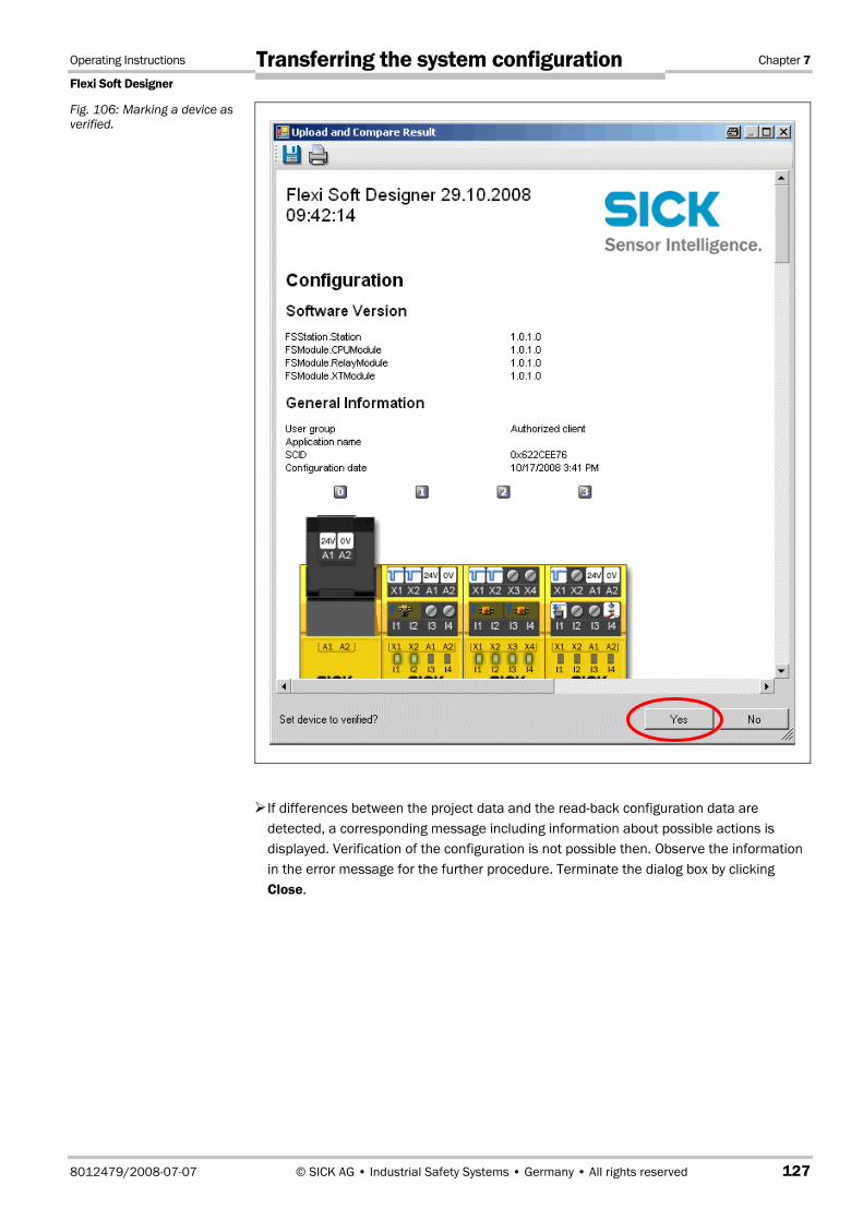
Operating Instructions Chapter 7
Flexi Soft Designer
8012479/2008-07-07 © SICK AG • Industrial Safety Systems • Germany • All rights reserved 127
Transferring the system configuration
If differences between the project data and the read-back configuration data are detected, a corresponding message including information about possible actions is displayed. Verification of the configuration is not possible then. Observe the information in the error message for the further procedure. Terminate the dialog box by clicking Close.
Fig. 106: Marking a device as verified.

Chapter 7 Operating instructions
Flexi Soft Designer
128 © SICK AG • Industrial Safety Systems • Germany • All rights reserved 8012479/2008-07-07
Transferring the system configuration
If the verification is completed successfully, a "Read in and compare" report that provides the most important project information is created subsequently. You can print out or store this report.
The query whether the device is to be marked as verified is displayed in the lower part of the report window. Only if the device and the corresponding configuration have been marked as verified, is the "Auto Start mode" in the configuration of the main module active. Logging in as an authorised user is required in order to mark the device as "verified". The status verified/not verified is indicated in the lower right-hand corner of the Flexi Soft Designer and by the CV LED at the Flexi Soft main module lighting up.
Fig. 107: Verification failed

Operating Instructions Chapter 7
Flexi Soft Designer
8012479/2008-07-07 © SICK AG • Industrial Safety Systems • Germany • All rights reserved 129
Transferring the system configuration
The verification flag is included in copying when the data are read back into the system plug and are also transferred automatically to each safety controller to which the configuration data are duplicated.
The safety controller is also ready to use when the configuration is only validated and not verified or does not have a write protection. The "Auto run mode" function of the main module, i.e., the automatic programme start after the voltage has been switched on, is not possible then.
The dialog box for verification is only displayed after a request by the user in order to ensure that the verification process does not have to be passed through every time the configuration is changed or new project data uploaded.
In order to validate the Flexi Soft system, the safety functions at the machine or system have to be checked completely and have to function perfectly. With regard to its content, the validation is identical to the the technical test taking place when the Flexi Soft system is commissioned.
Fig. 108: Verification successful
Note

Chapter 7 Operating instructions
Flexi Soft Designer
130 © SICK AG • Industrial Safety Systems • Germany • All rights reserved 8012479/2008-07-07
Transferring the system configuration
7.4 Activating the write protection of the configuration in the control system
A verified configuration can be protected against accidental changes by activating the write protection. The write protection can be set and deactivated in the Flexi Soft Designer by using the lock symbol in the hardware configuration to the left of the main module.
The write protection is included in copying when the data are transferred to the system plug and are also transferred automatically to each safety controller to which the configuration data are duplicated.

Operating Instructions Chapter 8
Flexi Soft Designer
8012479/2008-07-07 © SICK AG • Industrial Safety Systems • Germany • All rights reserved 131
Device states of the Flexi Soft system
8 Device states of the Flexi Soft system The Flexi Soft system knows different device states during operation. Some device states require a user intervention, e.g. the change in the state from Stop to Start using the Flexi Soft Designer. Other states are based on the internal self-test of the Flexi Soft system, e.g. Internal error. The following table summarises the device states of the Flexi Soft system.
MS LED Meaning
Off No/incorrect supply voltage
Red/green flashing (1 Hz) Self-test and system initialisation
Green flashing (1 Hz) Ready for operation
Green illuminated Application is being carried out
Red flashing Correctable error in the controller module or a different module
Red illuminated Critical error
CV LED Meaning
Off Status unknown
Yellow flashing (1 Hz), synchronous with red MS LED
Invalid configuration
Yellow flashing (2 Hz) Supply voltage may not be interrupted until the storage process has been completed
Yellow flashing (1 Hz), alternatively with red MS LED
Valid, but unverified configuration: error exists
Yellow flashing (1 Hz) Valid, but unverified configuration
Yellow illuminated Valid and verified configuration
Table 85: Device status and LED displays

Chapter 8 Operating instructions
Flexi Soft Designer
132 © SICK AG • Industrial Safety Systems • Germany • All rights reserved 8012479/2008-07-07
Device states of the Flexi Soft system
8.1.1 Change in the device state
Specific state changes in the Flexi Soft system are carried out manually in the Flexi Soft Designer. These changes in the device state are:
Change from Stop to Start
Change from Start to Stop
In order to change the device state, use the Stop and Start icon next to the representation of the modules in the hardware configuration.
Fig. 109: Stop-Start icon

Operating Instructions Chapter 8
Flexi Soft Designer
8012479/2008-07-07 © SICK AG • Industrial Safety Systems • Germany • All rights reserved 133
Device states of the Flexi Soft system
8.1.2 Auto Start mode and normal state
The Flexi Soft system can adopt the Start state directly after the supply voltage has been switched on if the required conditions are fulfilled. This automatic transition is called the Auto Start mode. The following conditions have to be fulfilled for the Auto Start mode:
A user configuration with regard to the software and hardware configuration has been created and downloaded successfully to a corresponding hardware.
The configuration has been uploaded back to the device and verified using "Read in and compare".
The Auto Start mode in the configuration is activated (activated in the basic setting). The Auto Start mode is switched on or off in the hardware configuration by double-clicking the CPU main module in the Settings tab.
In an unverified state, the Flexi Soft system waits for a command from the Flexi Soft Designer for the transition from the Stop to the Start state. The SELFTEST state has to have been completed successfully for this command.
When the Auto Start mode is deactivated, the Flexi Soft system does not change automatically to the Start state after the SELFTEST state after an interruption of the voltage supply in the Stop state has occurred. Then, you have to change to the Start mode manually in order to start the system.
Note

Chapter 9 Operating instructions
Flexi Soft Designer
134 © SICK AG • Industrial Safety Systems • Germany • All rights reserved 8012479/2008-07-07
Technical commissioning
9 Technical commissioning The configuration of the Flexi Soft system has to be completed before you begin with the technical commissioning.
9.1 Wiring and voltage supply
When connecting the Flexi Soft system, observe the technical data in the Flexi Soft hardware operating instructions.
Connect the individual field devices to the corresponding signal connections and check for each safety input, test/signal output and safety output whether these behave as required for the application. Diagnostics information from the Flexi Soft LEDs support you in validating the individual field signals. Check whether the external circuit, the realisation of the wiring, the choice of the pick-ups and their location at the machine fulfil the required safety level.
Eliminate any faults (e.g. incorrect wiring or crossed signals) at each safety input, test/signal output or safety output before you continue with the next step.
Switch on the voltage supply. As soon as the supply voltage is applied to the connections A1 and A2 of the controller module CPU0/CPU1 or the XTIO modules, the Flexi Soft system automatically carries out the following steps:
– internal self-test
– loading of the saved configuration
– testing of the loaded configuration for validity
The system does not start up if the steps described above could not be carried out successfully. If there is an error, this is indicated correspondingly by a LED (see the Flexi Soft hardware operating instructions) and the Flexi Soft system only transfers Inactive (failsafe) values.
9.2 Transferring the configuration After you have configured the hardware and the logic in the Flexi Soft system and have checked whether they are correct, transfer the configuration to the Flexi Soft system via the Flexi Soft Designer.
ATTENTION

Operating Instructions Chapter 9
Flexi Soft Designer
8012479/2008-07-07 © SICK AG • Industrial Safety Systems • Germany • All rights reserved 135
Technical commissioning
9.3 Technical test and commissioning The machine or system that is protected by a Flexi Soft safety controller may only be started up after a successful technical check of all the safety functions. The technical test may only be performed by professionals trained accordingly.
The technical test includes the following test items:
Uniquely mark all the connection cables and connectors at the Flexi Soft system in order to avoid confusion. Since the Flexi Soft system has several connections of the same design, you must ensure that loosened connection cables are not connected back to the wrong connection.
Verify the configuration of the Flexi Soft system.
Check the signal paths and the correct inclusion in higher-level controllers.
Check the correct data transfer from and to the Flexi Soft safety controller.
Check the logic programme of the safety controller.
Completely document the configuration of the entire system, of the individual devices and the results of the safety check.
Check the safety functions of the machine or system completely and ensure that the safety functions function perfectly.
In order to prevent unintentional overwriting of the configuration, activate the write protection of the configuration parameters of the Flexi Soft system. Modifications are now no longer possible unless the write protection has been deactivated.

Chapter 10 Operating instructions
Flexi Soft Designer
136 © SICK AG • Industrial Safety Systems • Germany • All rights reserved 8012479/2008-07-07
Troubleshooting and error elimination
10 Troubleshooting and error elimination
Error / Error message Cause Remedy
When Flexi Soft Designer is started, the following or a similar error message is displayed: "DLL not found - the Dynamic Link Library "mscoree.dll" was not found in the specified path.
Specify the registration key HKLM\Software\Microsoft\ NETFramework\InstallRoot so that it refers to the installation location of the .NET Framework."
Microsoft .NET Framework is not installed on the PC.
Install a suitable version of Microsoft.NET Framework. Ask your system administrator if appropriate. NET Framework is available for downloading on the internet pages of Microsoft.
Note:
Install .NET Framework 2.0 under Windows 98 / ME / 2000.
Install .NET Framework 3.0 or higher under Windows XP with ServicePack 2 or higher / 2003 Server.
.NET Framework is not available for older versions of Windows.
Table 86: Errors and error elimination

SICK AG | Waldkirch | Germany | www.sick.com
8012
479/
2008
-07-
07 ∙ T
L/VD
∙ Pr
inte
d in
Ger
man
y (2
008-
12) ∙
Sub
ject
to c
hang
e w
ithou
t not
ice
∙ The
spe
cifie
d pr
oduc
t fea
ture
s an
d te
chni
cal d
ata
do n
ot re
pres
ent a
ny g
uara
ntee
∙ 02
A4
sw in
t32 Australia
Phone +61 3 9497 4100 1800 33 48 02 – tollfreeE-Mail [email protected]
Belgium/LuxembourgPhone +32 (0)2 466 55 66E-Mail [email protected]
BrasilPhone +55 11 3215-4900E-Mail [email protected]
Ceská RepublikaPhone +420 2 57 91 18 50E-Mail [email protected]
ChinaPhone +852-2763 6966E-Mail [email protected]
DanmarkPhone +45 45 82 64 00E-Mail [email protected]
DeutschlandPhone +49 211 5301-260E-Mail [email protected]
EspañaPhone +34 93 480 31 00E-Mail [email protected]
FrancePhone +33 1 64 62 35 00E-Mail [email protected]
Great BritainPhone +44 (0)1727 831121E-Mail [email protected]
IndiaPhone +91–22–4033 8333E-Mail [email protected]
IsraelPhone +972-4-999-0590E-Mail [email protected]
ItaliaPhone +39 02 27 43 41E-Mail [email protected]
JapanPhone +81 (0)3 3358 1341E-Mail [email protected]
NederlandsPhone +31 (0)30 229 25 44E-Mail [email protected]
Norge Phone +47 67 81 50 00E-Mail [email protected]
ÖsterreichPhone +43 (0)22 36 62 28 8-0E-Mail [email protected]
PolskaPhone +48 22 837 40 50E-Mail [email protected]
Republic of KoreaPhone +82-2 786 6321/4E-Mail [email protected]
Republika SlowenijaPhone +386 (0)1-47 69 990E-Mail [email protected]
RomâniaPhone +40 356 171 120 E-Mail [email protected]
RussiaPhone +7 495 775 05 34E-Mail [email protected]
SchweizPhone +41 41 619 29 39E-Mail [email protected]
SingaporePhone +65 6744 3732E-Mail [email protected]
SuomiPhone +358-9-25 15 800E-Mail [email protected]
SverigePhone +46 10 110 10 00E-Mail [email protected]
TaiwanPhone +886 2 2375-6288E-Mail [email protected]
TürkiyePhone +90 216 587 74 00E-Mail [email protected]
USA/Canada/MéxicoPhone +1(952) 941-6780 1 800-325-7425 – tollfreeE-Mail [email protected]
More representatives and agencies in all major industrial nations at www.sick.com