flc 3701 - mpi extension card
TRANSCRIPT

FLC 3701 - MPI Extension Card
INSTALLATION GUIDEIG-0029-00 1.2 en-US ENGLISH
Important User InformationDisclaimerThe information in this document is for informational purposes only. Please inform HMS Industrial Networks of anyinaccuracies or omissions found in this document. HMS Industrial Networks disclaims any responsibility or liabilityfor any errors that may appear in this document.
HMS Industrial Networks reserves the right to modify its products in line with its policy of continuous productdevelopment. The information in this document shall therefore not be construed as a commitment on the part ofHMS Industrial Networks and is subject to change without notice. HMS Industrial Networks makes no commitmentto update or keep current the information in this document.
The data, examples and illustrations found in this document are included for illustrative purposes and are onlyintended to help improve understanding of the functionality and handling of the product. In view of the wide rangeof possible applications of the product, and because of the many variables and requirements associated with anyparticular implementation, HMS Industrial Networks cannot assume responsibility or liability for actual use based onthe data, examples or illustrations included in this document nor for any damages incurred during installation of theproduct. Those responsible for the use of the product must acquire sufficient knowledge in order to ensure that theproduct is used correctly in their specific application and that the application meets all performance and safetyrequirements including any applicable laws, regulations, codes and standards. Further, HMS Industrial Networks willunder no circumstances assume liability or responsibility for any problems that may arise as a result from the use ofundocumented features or functional side effects found outside the documented scope of the product. The effectscaused by any direct or indirect use of such aspects of the product are undefined and may include e.g. compatibilityissues and stability issues.
FLC 3701 - MPI Extension Card Installation Guide IG-0029-00 1.2 en-US
FLC 3701 - MPI Extension Card Installation Guide IG-0029-00 1.2 en-US
Table of Contents Page
1 Preface ................................................................................................................................. 31.1 About This Document .......................................................................................................3
1.2 Document history ............................................................................................................3
1.3 Related Documents ..........................................................................................................3
1.4 Trademark Information .....................................................................................................3
2 Product Summary................................................................................................................ 4
3 Safety, Environmental & Regulatory Information ............................................................. 53.1 Scope.............................................................................................................................5
3.2 ESD Damage Prevention ....................................................................................................5
3.3 Applicable Directives, Standards and Compliances .................................................................5
4 Hardware Description ......................................................................................................... 74.1 Mechanical Layout and Interfaces .......................................................................................7
4.2 Extension Card Label ........................................................................................................7
4.3 Front Panel LEDs ..............................................................................................................8
4.4 Ewon Flexy Extension Card Environmental Conditions ............................................................8
4.5 MPI Port Specification.......................................................................................................9
5 Plugging the Extension Card into the Base Unit.............................................................. 105.1 Base Unit Slot Compatibility ............................................................................................. 10
5.2 Extension Card Insertion.................................................................................................. 11
6 Powering on the Base Unit with its Extension Cards ...................................................... 13
7 Check Card Detection on the Embedded Web Page ....................................................... 147.1 Connecting to the Embedded Web Server .......................................................................... 14
7.2 Detected Cards Displayed in the System Page ..................................................................... 14

This page intentionally left blank

Preface 3 (16)
1 Preface1.1 About This Document
This document describes the hardware of the FLC 3701 - MPI extension card which is operationalwith the Ewon Flexy 205 only.
The Ewon Flexy family is a range of modular industrial gateway/router and as its name EwonFlexy suggests, it has been designed to enable numerous different combinations of base unitswith extension cards.
For additional related documentation and file downloads, please visit www.ewon.biz/support.
1.2 Document historyVersion Date Description
1.0 2018-01-19 First release1.1 2018-02-26 Changed: Plugging the Extension Card into the Base Unit, p. 10
1.2 2019-09-03 Changed: Safety, Environmental & Regulatory Information, p. 5Changed: Ewon Flexy Extension Card Environmental Conditions, p. 8
1.3 Related DocumentsDocument Author Document ID
Ewon Flexy 205 HMS IG-0028-00
1.4 Trademark InformationEwon® is a registered trademark of HMS Industrial Networks SA. All other trademarks mentionedin this document are the property of their respective holders.
FLC 3701 - MPI Extension Card Installation Guide IG-0029-00 1.2 en-US
Product Summary 4 (16)
2 Product SummaryThe present Installation Guide is focusing on the FLC 3701 - MPI extension card which is not astandalone product and must be inserted in a Flexy 205 base unit to work.
The Flexy 205 has its own Installation Guide which can be found in the Related Documents, p. 3.
This guide also addresses shortly how the extension cards integrate the Ewon Flexy as well assome recommendations on how to mount them.
FLC 3701 - MPI Extension Card Installation Guide IG-0029-00 1.2 en-US

Safety, Environmental & Regulatory Information 5 (16)
3 Safety, Environmental & Regulatory Information3.1 Scope
The present heading addresses Safety, Environmental & Regulatory Information about the FLC3701 - MPI extension card.
This extension card belongs to the same compliance frame than the Flexy 205. In the presentcase of a telecommunication extension card, additional directives, standards and instructionsapply.
3.2 ESD Damage Prevention
Always use ESD precautions when handling extension cards and / or opened base unit asthey contain parts and assemblies susceptible to be damaged by electrostatic discharge(ESD).
The extension card described in this document is a module exposing both sides of an electronicprinted circuit board. Therefore, it is packed in an antistatic ESD bag. In order to avoid ESDdamage, the product must be handled with the necessary precaution including:
• Grounded ESD protective work surface
• Personnel grounding
3.3 Applicable Directives, Standards and CompliancesThe extension card described in the present document belongs to class A InformationTechnology Equipment (ITE). In a domestic environment this product may cause radiointerference in which case the user may be required to take appropriate measures.
3.3.1 Applicable European DirectivesThe FLC 3701 - MPI extension card is in conformity with the following EC directives:
• RoHS Directive 2011/65/EU
• EMC Directive 2014/30/EU
3.3.2 Applicable Safety StandardsThe FLC 3701 is in conformity with the following safety standards:
• IEC / EN 60950-1
• UL 60950-1
• CSA-C22.2 No 60950-1-07
• EN/IEC 62368-1
• UL 62368-1
• CAN 62368-1
3.3.3 FCC ComplianceThe FLC 3701 complies with Part 15 of the FCC Rules. Operating is subject to the following twoconditions:
FLC 3701 - MPI Extension Card Installation Guide IG-0029-00 1.2 en-US

Safety, Environmental & Regulatory Information 6 (16)
• This product may not cause harmful interference
• This product must accept any interference received, including interference that may causeundesired operation.
3.3.4 CertificationsThe FLC 3701 has been certified by authorized bodies:
• UL Certificate of Compliance (COC) # 20190529_E350576
• CB certificate # DK-84039-UL
These certificates can be downloaded as PDF files on the Ewon support web site: www.ewon.biz/support
FLC 3701 - MPI Extension Card Installation Guide IG-0029-00 1.2 en-US
Hardware Description 7 (16)
4 Hardware Description4.1 Mechanical Layout and Interfaces
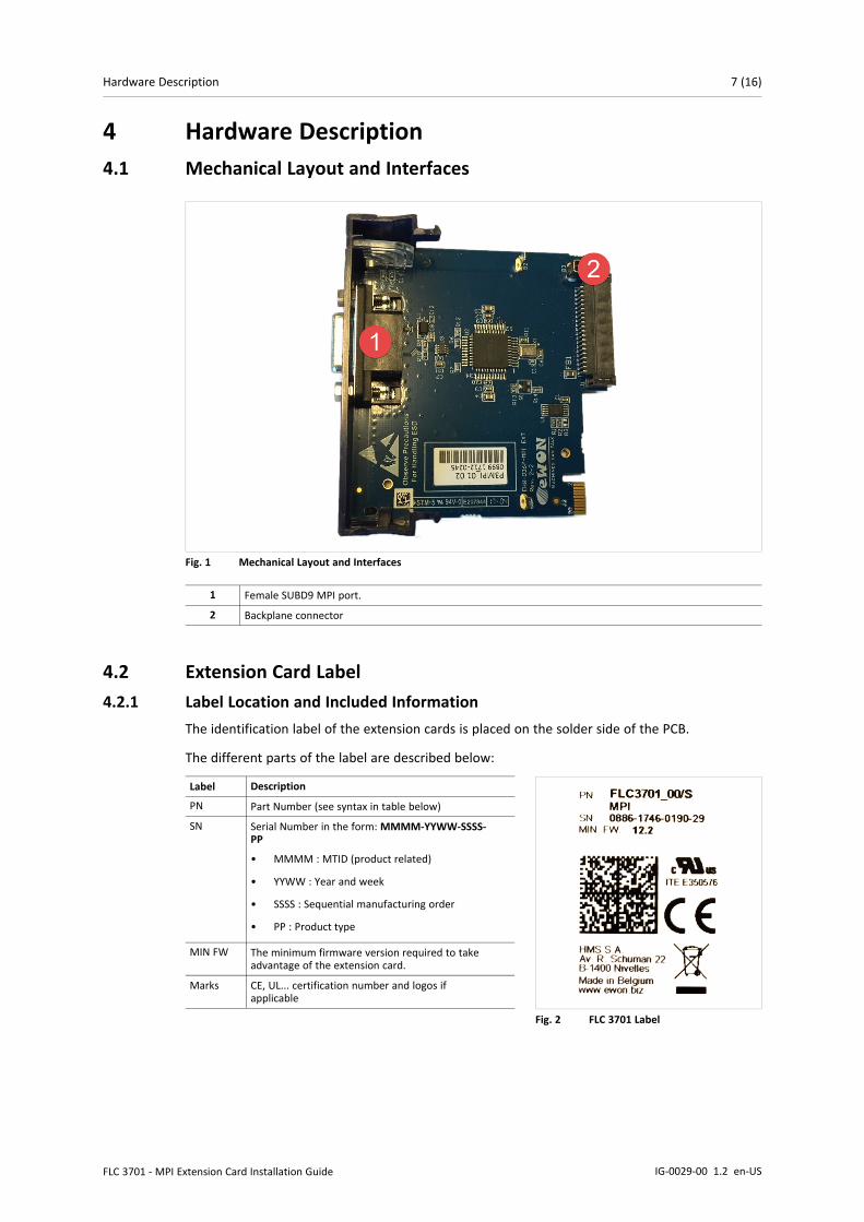
Fig. 1 Mechanical Layout and Interfaces
1 Female SUBD9 MPI port.
2 Backplane connector
4.2 Extension Card Label4.2.1 Label Location and Included Information
The identification label of the extension cards is placed on the solder side of the PCB.
The different parts of the label are described below:
Fig. 2 FLC 3701 Label
Label Description
PN Part Number (see syntax in table below)
SN Serial Number in the form: MMMM-YYWW-SSSS-PP
• MMMM : MTID (product related)
• YYWW : Year and week
• SSSS : Sequential manufacturing order
• PP : Product type
MIN FW The minimum firmware version required to takeadvantage of the extension card.
Marks CE, UL... certification number and logos ifapplicable
FLC 3701 - MPI Extension Card Installation Guide IG-0029-00 1.2 en-US
Hardware Description 8 (16)
4.2.2 Part Number Structure for Extension CardsFLYXXXX_00/S
FL FL is the prefix for the extensions of the Ewon Flexy family Only FL (constant)
Y 1 alphabetic sign (CAP)Defines the slots of the base module in which the extensioncard can be inserted.
A 2 first slotsonly
●●○○
B 2 last slotsonly
○○●●
X Any slots ●●●●
C Any slots.Available forFlexy 205 only.
○○○○
XXXX_00 The extension card type. The suffix _00 is used for software options.
/S The suffix might have an optional “/” characterIt might also be blank or include “S” character => Indicates compliance with the UL/IEC/EN 60950standard.
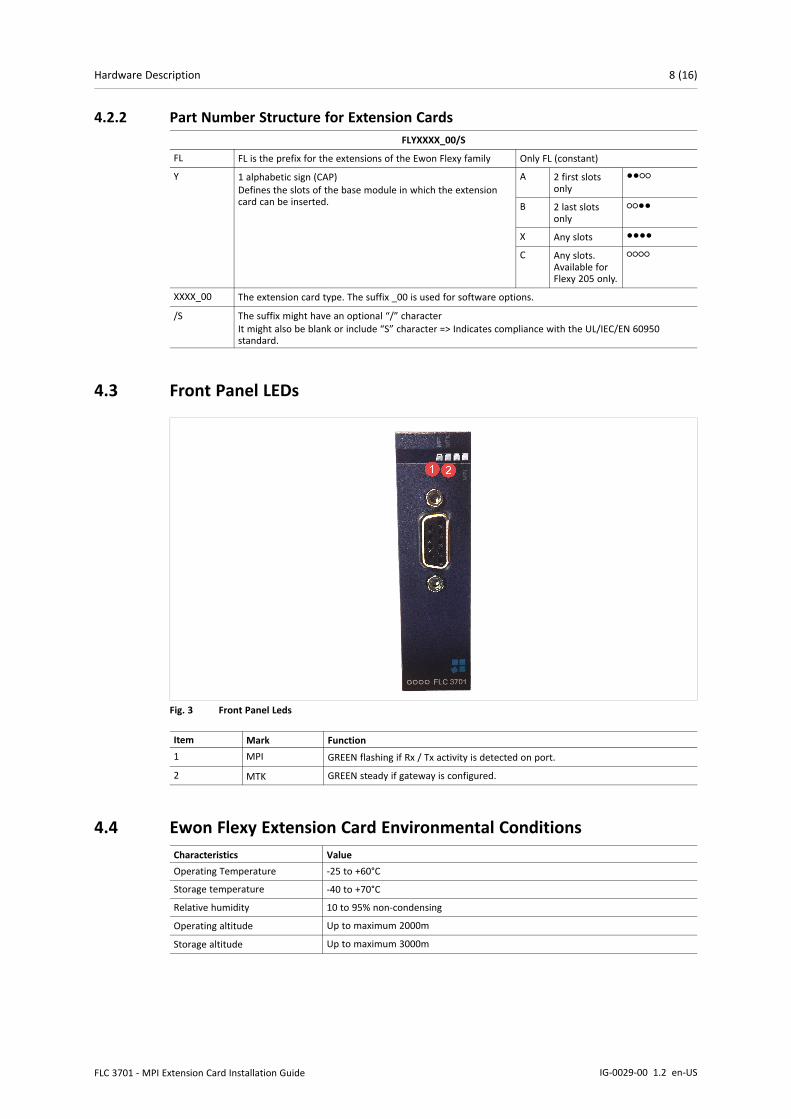
4.3 Front Panel LEDs
Fig. 3 Front Panel Leds
Item Mark Function1 MPI GREEN flashing if Rx / Tx activity is detected on port.
2 MTK GREEN steady if gateway is configured.
4.4 Ewon Flexy Extension Card Environmental ConditionsCharacteristics ValueOperating Temperature -25 to +60°C
Storage temperature -40 to +70°C
Relative humidity 10 to 95% non-condensing
Operating altitude Up to maximum 2000m
Storage altitude Up to maximum 3000m
FLC 3701 - MPI Extension Card Installation Guide IG-0029-00 1.2 en-US

Hardware Description 9 (16)
4.5 MPI Port SpecificationCharacteristic ValuePhysical mode MPI (1500V galvanic isolation through the power supply isolation from ground).
Baud rates From 9.6 kBauds to 12.0 MBauds.Polarization 100 kΩTermination NoneSUBD9 femaleconnector pinout
Pin # MP1 –
2 –
3 B+4 –
5 GND6 –
7 –
8 A-9 –
FLC 3701 - MPI Extension Card Installation Guide IG-0029-00 1.2 en-US
Plugging the Extension Card into the Base Unit 10 (16)
5 Plugging the Extension Card into the Base Unit5.1 Base Unit Slot Compatibility
The FLC 3701 must be inserted in one of the “Type C” slots of the base unit.
The reference code of the extension cards includes a letter defining their compatibility:
• FLC xxxx: designate cards that fit into “Type C” slots.
In addition to the card reference, each type of extension card bears a visual compatibility symbolon its front panel:
Design Slot Type Flexy 205 Location Flexy 10x & 20x○○○○ Type C Any slot Not compatible
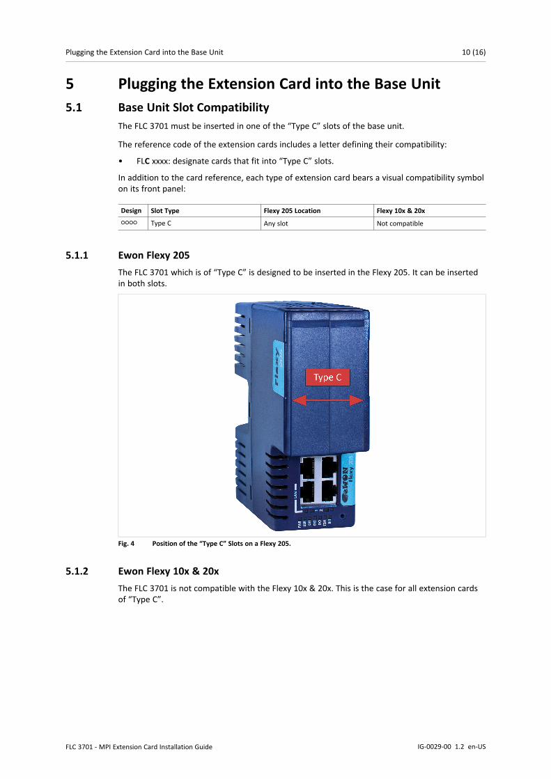
5.1.1 Ewon Flexy 205The FLC 3701 which is of “Type C” is designed to be inserted in the Flexy 205. It can be insertedin both slots.
Fig. 4 Position of the “Type C” Slots on a Flexy 205.
5.1.2 Ewon Flexy 10x & 20xThe FLC 3701 is not compatible with the Flexy 10x & 20x. This is the case for all extension cardsof “Type C”.
FLC 3701 - MPI Extension Card Installation Guide IG-0029-00 1.2 en-US

Plugging the Extension Card into the Base Unit 11 (16)
5.2 Extension Card Insertion5.2.1 How to Insert into the Flexy Base Unit
Wait 30 seconds after turning off the equipment before inserting (or removing) an extensioncard to avoid possible damage to the base unit and the extension cards.
Remove the slot filler of the location the new card will be inserted. To do so, press on both endsof the cover, note that the hooks are off-centered.
Fig. 5 Remove / Insert an Extension Card or Slot Filler.
1 Hooks to be pressed are off-centered. Press while pulling upwards.
2 Guides to slide down/up the FLC 3701.
Insert the extension card carefully and slide it down until the hook clicks. Make sure the card iscompletely inserted. DO NOT insist if a resistance is felt when trying to insert the card.
Boot the unit for the inserted extension cards to be detected. The web interface of the Flexybase unit has a diagnostic page showing the extension cards in their order of detection (from leftto right).
FLC 3701 - MPI Extension Card Installation Guide IG-0029-00 1.2 en-US

Plugging the Extension Card into the Base Unit 12 (16)
5.2.2 Insertion of Multiple FLC 3701Detection Order
The boot sequence of the base unit includes an automated detection of the inserted extensioncards. This detection is done sequentially, slot per slot starting from left to right (when holdingthe base unit with its logo on the right side).
Software Compatibility
The base unit allows the insertion of multiple extension cards, sometimes of the same type.Some configurations including multiple extension cards, even if mechanically acceptable, are notsupported by the embedded software. Cards in excess are ignored during the automateddetection process which means that the base unit and its running extension cards will operatenormally.
The Flexy firmware currently supports up to 1 FLC 3701.
The ignored card(s) will appear in the Diagnostic > Status > System Info > System but they willnot be functional.
Fig. 6 Order of the Extension Cards
The picture above shows an example of a configuration that would be OK mechanically andpower wise but would not be supported by the firmware.
During the boot process, the first 2 serial port extension cards are detected and both can be used.
In case of 2 single Ethernet cards, these 2 cards are also detected but the second Ethernet card isnot supported by the firmware and cannot be used. The presence of this “ignored” card in thebase unit does not alter the operation of the base unit itself nor does it alter its “accepted”extension cards.
5.2.3 Power RequirementsThe “Power Requirements” concept doesn’t apply to the Flexy 205 and its inserted extensioncards.
FLC 3701 - MPI Extension Card Installation Guide IG-0029-00 1.2 en-US

Powering on the Base Unit with its Extension Cards 13 (16)
6 Powering on the Base Unit with its Extension CardsWhen the base unit is powered on, it takes approximately 25 seconds for the unit to go throughits self-test procedure. The slots in which the extension cards have been inserted and their typeare detected during this process.
If the boot process completes normally, the following LED status should be observed:
• Base unit : USR LED flashing green slowly
• Extension card : None
If the USR LED of the base unit is flashing red, it might be because the extension card wasimproperly inserted (for example in a wrong slot).
FLC 3701 - MPI Extension Card Installation Guide IG-0029-00 1.2 en-US

Check Card Detection on the Embedded Web Page 14 (16)
7 Check Card Detection on the Embedded Web PageThe Flexy extension cards require no software configuration. They are automatically detected bythe base unit when the device boots.
7.1 Connecting to the Embedded Web ServerConfigure the network parameters to set the computer being used to reach the web interface onthe same IP range than the LAN of the Ewon device.
Once both devices are in the same IP range, connect the PC to one of the LAN port of the Ewondevice.
Open an Internet browser and access the homepage of the Ewon device by typing the LAN IPaddress in the URL field (the default address is http://10.0.0.53).
A dialog box will pop-up asking for credentials. Default ones are:
• login: adm
• password: adm
For security reasons, changing the default password adm is an absolute requirement. Tochange it, from the menu bar, click on Setup > Users and double click on the adm entry toedit and save its password.
7.2 Detected Cards Displayed in the System PageOnce connected to the embedded web pages of the Ewon device, the homepage displays thesystem status including detected extension cards.
To access in details the system status summary, click on Diagnostic > Status > System Info >System.
FLC 3701 - MPI Extension Card Installation Guide IG-0029-00 1.2 en-US

This page intentionally left blank

last page
© 2019 HMS Industrial NetworksBox 4126300 04 Halmstad, Sweden
[email protected] IG-0029-00 1.2 en-US / 2019-09-03 / 14618