flat slabs 8.7.1 definition and constructionauthor.uthm.edu.my/uthm/www/content/lessons/2969/flat...
TRANSCRIPT
FLAT SLABS 8.7.1 Definition and construction
The flat slab is defined in BS8110: Part 1, clause 1.2.2.1, as a slab with or without drops, supported generally without beams by columns with or without column heads. The code states that the slab may be solid or have recesses formed on the soffit to give a waffle slab. Only solid slabs will be discussed. Flat slab construction is shown in Fig. 8.20 for a building with circular internal columns, square edge columns and drop panels. The slab is thicker than that required in T-beam floor slab construction but the omission of beams gives a smaller storey height for a given clear height and simplification in construction and formwork. Various column supports for the slab either without or with drop panels are shown in Fig. 8.21. The effective column head is defined in the code. 8.7.2 General code provisions The design of slabs is covered in BS8110: Part 1, section 3.7. General requirements are given in clause 3.7.1, as follows. 1. The ratio of the longer to the shorter span should not exceed 2. 2. Design moments may be obtained by (a) Equivalent frame method (b) Simplified method (c) Finite element analysis

Fig. 8.20 (a) Floor plan; (b) section.

Fig. 8.21 (a) Slab without drop panel; (b) slab with drop panel and flared column head.
3. The effective dimension lh of the column head is taken as the lesser of (a) the actual dimension lhc or (b) lh max= lc+2(dh−40) where lc is the column dimension measured in the same direction as lh. For a flared head lhc is measured 40 mm below the slab or drop. Column head dimensions and the effective dimension for some cases are shown in Fig. 8.22 (see also BS8110: Part 1, Fig. 3.11). 4. The effective diameter of a column or column head is as follows: (a) For a column, the diameter of a circle whose area equals the area of the column (b) for a column head, the area of the column head based on the effective dimensions defined in requirement 3 The effective diameter of the column or column head must not be greater than one-quarter of the shorter span framing into the column.

5. Drop panels only influence the distribution of moments if the smaller dimension of the drop is at least equal to one-third of the smaller panel dimension. Smaller drops provide resistance to punching shear. 6. The panel thickness is generally controlled by deflection. The thickness should not be less than 125 mm. 8.7.3 Analysis The code states that normally it is sufficient to consider only the single load case of maximum design load, 1.4× dead load + 1.6× imposed load on all spans. The following two methods of analysis are set out in section 3.7.2 of the code to obtain the moments and shears for design. (a) Frame analysis method
The structure is divided longitudinally and transversely into frames consisting of columns and strips of slab. Either the entire frame or subframes can be analyzed by moment distribution. This method is not considered further.
(b) Simplified method Moments and shears may be taken from Table 3.19 of the code for structures where lateral stability does not depend on slab-column connections. The following provisions apply: 1. Design is based on the single load case mentioned above; 2. The structure has at least three rows of panels of approximately equal span in the direction considered. The design moments and shears for internal panels from Table 3.19 of the code are given in Table 8.5. Refer to the code for the complete table.
8.7.4 Division of panels and moments
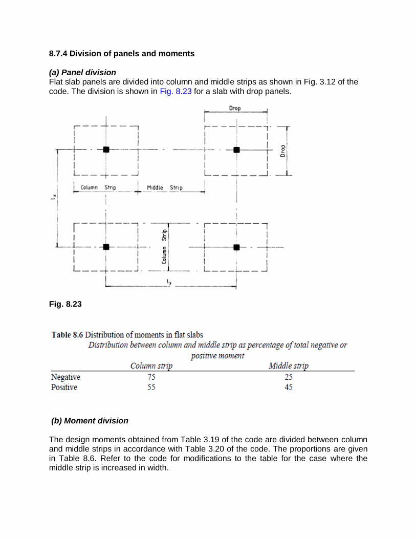
(a) Panel division Flat slab panels are divided into column and middle strips as shown in Fig. 3.12 of the code. The division is shown in Fig. 8.23 for a slab with drop panels.
Fig. 8.23
(b) Moment division The design moments obtained from Table 3.19 of the code are divided between column and middle strips in accordance with Table 3.20 of the code. The proportions are given in Table 8.6. Refer to the code for modifications to the table for the case where the middle strip is increased in width.

8.7.5 Design of internal panels and reinforcement details
The slab reinforcement is designed to resist moments derived from Tables 3.19 and 3.20 of the code. The code states in clause 3.7.3.1 for an internal panel that two-thirds of the amount of reinforcement required to resist negative moment in the column strip should be placed in a central zone of width one-half of the column strips. Reinforcement can be detailed in accordance with the simplified rules given in clause 3.12.10.3.1 and Fig. 3.25 of the code (section 8.2.3(d) above). 8.7.6 Design of edge panels
Design of edge panels is not discussed. Reference should be made to the code for design requirements. The design is similar to that for an interior panel. The moments are given in Table 3.19 of the code. The column strip is much narrower than for an internal panel (Fig. 3.13 of the code). The slab must also be designed for large shear forces as shown in Fig. 3.15 of the code. 8.7.7 Shear force and shear resistance
The code states is clause 3.7.6.1 that punching shear around the column is the critical consideration in flat slabs. Rules are given for calculating the shear force and checking shear stresses. (a) Shear forces
Equations are given in the code for calculating the design effective shear force Veff at a shear perimeter in terms of the design shear Vt transferred to the column. The equations for Veff include an allowance for moment transfer, i.e. the design moment transferred from the slab to the column. The code states that in the absence of calculations it is satisfactory to take Veff=1.15Vt for internal columns in braced structures with approximately equal spans. To calculate Vt all panels adjacent to the column are loaded with the maximum design load. (b) Shear resistance Shear due to concentrated loads on slabs is given in BS8110: Part 1, section 3.7.7. This was discussed in section 5.1.5. The checks are as follows. (i) Maximum shear stress at the face of the column

where u0 is the perimeter of the column (Fig. 8.24) and V is the design ultimate value of the concentrated load. (ii) Shear stress on a failure zone 1.5d from the face of the column
Fig. 8.24 where u is the perimeter of the failure zone 1.5d from the face of the column (Fig. 8.24). If v is less than the design concrete shear stress given in Table 3.9 of the code, no shear reinforcement is required. If the failure zone mentioned above does not require shear reinforcement, no further checks are required. It is not desirable to have shear reinforcement in light or moderately loaded slabs. 8.7.8 Deflection
The code states in clause 3.7.8 that for slabs with drops, if the width of drop is greater than one-third of the span, the rules limiting span-to-effective depth ratios given in section 3.4.6 of the code can be applied directly. In other cases span-to-effective depth ratios are to be multiplied by 0.9. The check is to be carried out for the most critical direction, i.e. for the longest span. The modification factor for tension reinforcement is based on the total moment at mid-span of the panel and the average of column strip and middle strip tension steel. 8.7.9 Crack control
The bar spacing rules for slabs given in clause 3.12.11.2.7 of the code apply.

Example 8.6 Internal panel of a flat slab floor (a) Specification The floor of a building constructed of flat slabs is 30 m×24 m. The column centres are 6 m in both directions and the building is braced with shear walls. The panels are to have drops of 3 m×3 m. The depth of the drops is 250 mm and the slab depth is 200 mm. The internal columns are 450 mm square and the column heads are 900 mm square. The loading is as follows: Dead load =self-weight + 2.5 kN/m2 for screed, floor finishes, partitions and ceiling Imposed load = 3.5 kN/m2 The materials are grade 30 concrete and grade 250 reinforcement. Design an internal panel next to an edge panel on two sides and show the reinforcement on a sketch. (b) Slab and column details and design dimensions A part floor plan and column head, drop and slab details are shown in Fig. 8.25. The drop panels are made one-half of the panel dimensions. The column head dimension lh0, 40 mm below the soffit of the drop panel, is 870 m. The effective dimension lh of the column head is the lesser of
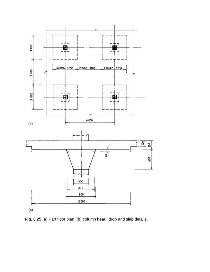
Fig. 8.25 (a) Part floor plan; (b) column head, drop and slab details.

1. lh0 = 870 mm and 2. lh max=450+2(600−40) = 1570 mm That is, lh=870 mm. The effective diameter of the column head is hc=(4×8702/π)1/2=981 mm < 1/4×6000=1500 mm hc=981 mm The effective span is l = 6000−2×981/3 = 5346 mm The column and middle strips are shown in Fig. 8.25(a). (c) Design loads and moments The average load due to the weight of the slabs and drops is [(9×0.25)+(27×0.2)]23.6/36 = 5.02 kN/m2 The design ultimate load is n = (5.02+2.5)1.4+(3.5×1.6) = 16.13 kN/m2 The total design load on the strip of slab between adjacent columns is F = 16.13×62 = 580.7 kN The moments in the flat slab are calculated using coefficients from Table 3.19 of the code and the distribution of the design moments in the panels of the flat slab is made in accordance with Table 3.20. The moments in the flat slab are as follows. For the first interior support,
−0.063 × 580.7 × 5.35= −195.7 kN m
For the centre of the interior span, +0.071 × 580.7 × 5.35= +220.6 kN m
The distribution in the panels is as follows. For the column strip
Negative moment =−0.75×195.7=−146.8 kN m Positive moment =0.55×220.6=121.3 kN m
For the middle strip
Negative moment =−0.25×195.7=−48.9 kN m Positive moment =0.45×220.6=99.3 kN m

(d) Design of moment reinforcement
The cover is 25 mm and 16 mm diameter bars in two layers are assumed. At the drop the effective depth for the inner layer is 250−25−16−8=201 mm In the slab the effective depth of the inner layer is 200−25−16−8=151 mm The design calculations for the reinforcement in the column and middle strip are made with width b=3000 mm. (i) Column strip negative reinforcement
From Fig. 4.13 this is less than 1.27 and thus
Provide a minimum of 19 bars 16 mm in diameter to give an area of 3819 mm2. Two-thirds of the bars or 13 bars are placed in the centre half of the column strips at a spacing of 125 mm. A further four bars are placed in each of the outer strips at a spacing of 190 mm. This gives 21 bars in total. (ii) Column strip positive reinforcement
From Fig. 4.13 100As/bd = 0.92. As=0.92×3000×151/100 = 4167.6 mm2 Provide 21 bars 16 mm in diameter to give an area of 4221 mm2 with a spacing of 150 mm.

(iii) Middle strip negative reinforcement
Provide 15 bars 12 mm in diameter to give an area of 1695 mm2 with a spacing of 200 mm. (iv) Middle strip positive reinforcement
M/bd2 = 1.45 100As/bd = 0.75 As = 3397.5 mm2
Provide 18 bars 16 mm in diameter to give an area of 3618 mm2 with a spacing of 175 mm. (e) Shear resistance (i) At the column face 40 mm below the soffit shear V = 1.15×16.13(36−0.872) = 653.7 kN The shear stress is
The maximum shear stress is satisfactory. (ii) At 1.5d from the column face
In the centre half of the column strip 16 mm diameter bars are spaced at 125 mm centres giving an area of 160.8 mm2/m.
The design concrete shear stress is vc = 0.79×(0.8)1/3(400/201)1/4(30/25)1/3/1.25
= 0.73 N/mm2
The shear stress is satisfactory and no shear reinforcement is required. (f) Deflection The calculations are made for the middle strip using the total moment at mid-span and the average of the column and middle strip tension steel. The basic span/d ratio is 26 (Table 3.10 of the code).
The modification factor is
The slab is satisfactory with respect to deflection. (g) Cracking The bar spacing does not exceed 3d, i.e. 603 mm for the drop panel and 453 mm for the slab. In accordance with BS8110: Part 1, clause 3.12.11.2.7, for grade 250 reinforcement the drop panel depth does not exceed 250 mm and so no further checks are required. (h) Arrangement of reinforcement
The arrangement of the reinforcement is shown in Fig. 8.26. Secondary reinforcement is required in the drop panel and slab to tie in the moment steel. The area required is 0.24% of grade 250 steel. The areas are as follows:

Drop panel 0.24×250×103/100=600 mm2/m 12 mm diameter bars at 180 mm centres to give an area of 628 mm2/m Slab 0.24×200×103/100=480 mm2/m 12 mm diameter bars at 220 mm centres to give an area of 514 mm2/m Note that the steel spacing are rationalized in Fig. 8.26. A mat of reinforcement is placed in the bottom of the drop panel. This laps with the reinforcement in the bottom of the slab.
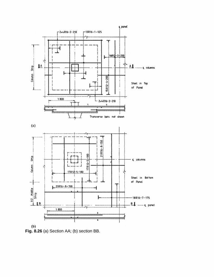
Fig. 8.26 (a) Section AA; (b) section BB.