flat-jack tests on old masonry buildingsrbento/tmp/severes/icem2012_3056.pdf · th15 international...
TRANSCRIPT

15th International Conference on Experimental Mechanics
ICEM15 1
PAPER REF: 3056
FLAT-JACK TESTS ON OLD MASONRY BUILDINGS
Ana Simões1 (*)
, António Gago2, Rita Bento
3, Mário Lopes
4
1, 2, 3, 4 ICIST, IST; Technical University of Lisbon, Portugal
(*)Email: [email protected]
ABSTRACT
In this work an experimental campaign with flat-jacks on old masonry buildings is presented
and discussed. The tests were carried out on load bearing masonry walls of an 18th
century
building of Lisbon downtown. They aimed the evaluation of the rubble stone masonry
deformability properties in compression and compressive strength (double flat-jack test) and
the shear strength parameters (shear flat-jack test). This study was developed within the scope
of the Portuguese research project SEVERES (www.severes.org).
Keywords: masonry, in situ tests, experimental results
INTRODUCTION
It is estimated that half of the existing building stock in Lisbon County is composed by old
masonry buildings (Ravara et al., 2001). The survey ‘Censos 2001’ (INE, 2002) estimated
that approximately 67% of these buildings are in need of structural intervention works and
that 10% are in an advanced stage of degradation. The functions that old buildings still have
nowadays, justify the concern about their structural safety and seismic vulnerability.
This study describes an experimental campaign developed to assess the physical and
mechanical properties of the old masonry buildings in the historical centre of Lisbon;
essential data to validate the numerical models that assess the seismic behaviour of the
buildings.
The exterior masonry walls of Lisbon old masonry buildings are generally made of rubble
limestone masonry with grit (red aggregate) or fragments of ceramic bricks, bounded by air
lime mortar. Due to the irregularity of the material and workmanship, the mechanical
characterization should be carried out on undisturbed and large dimension masonry
specimens. However, due to the historical value of the building most of the times the survey
has to be conducted with less destructive testing techniques.
The flat-jack test provides a relatively non-destructive way of determining the in situ
mechanical properties of masonry. This testing technique has been successfully used in
regular brick and stone masonry structures but its practice on rubble stone masonry structures
is not so common. In these cases the experimental procedures have to be adapted and
calibrated.
The experimental campaign with flat-jacks herein described was conducted on rubble stone
masonry bearing walls of an 18th
century building in Lisbon. The mechanical properties
analysed were: (i) deformability properties in compression and compressive strength (double
flat-jack test); and (ii) shear strength parameters (shear flat-jack test). In this article, the
experimental results obtained with the in situ flat-jack testing are presented and discussed.

Porto/Portugal, 22-27 July 2012
Editors: J.F. Silva Gomes and Mário A.P. Vaz 2
EXPERIMENTAL CAMPAIGN
The tests were carried out on an 18th
century building located in the historical downtown area
rebuilt after the 1755 earthquake. This typology of buildings (so called Pombalino’s
buildings) is characterized by a three-dimensional timber structure (named ‘gaiola
pombalina’) enclosed on the interior walls of the building and above the first storey.
Vaults and arches support the first storey floor, while the upper floors are composed by timber
beams usually placed perpendicular to the rubble stone masonry façade walls (Cardoso et al.,
2005). The roof with ceramic roof tiles is supported by timber trusses. The exterior walls are
made of rubble stone masonry with decreasing thickness with the height of the building.
The experimental tests were performed on the wall of the back façade at the ground floor
level (Fig. 1). At this location the wall has no openings and is thick enough to support the cuts
perpendicular to its surface without endangering the structure.
Fig. 1 Test site: back façade wall on the ground floor level and vertical cut B (dimensions in meters).
The flat-jacks used were manufactured according with the specifications of ASTM C 1196-04
(2004) and RILEM MDT.D.4 (2004). The flat-jack steel sheets are 0.12 centimetres (cm)
thick and have a semi-circular shape in plane (34.5 cm x 25.5 cm - Fig. 2), as recommended
for irregular stone masonry structures (Rossi, nd).
Fig. 2 Semi-circular flat-jack with (A) 34.5 cm and (B) 25.5 cm.
The deformation on the masonry surface were taken with a removal mechanical meter which
measures the relative distance between reference points (metal discs) disposed on the
masonry. The mechanical meter in use has a gauge length of 20.0 cm. Three measurement
repetitions are required at each row of points, the final value being the average of the
measurements.
The cuts on the masonry were made by a circular saw. Steel sheets (shims) with the same
plane shape of the flat-jack were used to pack the flat-jack inside the cut and to protect the
equipment from the rough surface of the masonry or local swelling. Between the flat-jack and

15th International Conference on Experimental Mechanics
ICEM15 3
the shims, a sheet of painting paper wrapped in white paper is placed to print the effective
contact surface between the flat-jack and the cut (paper stamp).
DOUBLE FLAT-JACK TEST
The double flat-jack test supports the assessment of the masonry deformability properties in
compression. The test procedure is described in ASTM C 1197-04 (2004) and in RILEM
MDT.D.5 (2004). In this test two horizontal cuts, 40.0 cm spaced, were made in the wall
delimiting a masonry specimen to be tested under uniaxial compression.
Vertical and horizontal distances on selected points were recorded to provide the masonry
Young’s modulus and the Poisson ratio. The maximum pressure of the test may be used to
estimate the compressive strength of the masonry.
According to ASTM C 1197-04 (2004) and RILEM MDT.D.5 (2004), the flat-jacks have an
inherent stiffness which resists expansion when pressurized and therefore, the internal
pressure of the flat-jack is greater than the state of stress on the masonry. The flat-jacks have
to be calibrated to determine this conversion factor according with the procedure described on
ASTM C 1197-04 (2004) and in RILEM MDT.D.5 (2004). As a result, the state of
compression stress in the masonry (fm) is approximately equal to the flat-jack pressure (p)
multiplied by the calibration factor of the flat-jack (Ke) and the ratio (Kc) between the bearing
area of the flat-jack in contact with the masonry (Aje) and the bearing area of the cut (Acut),
according to equation (1):
In what concerns the deformability properties, the tangent Young’s modulus (Et) is given by
equation (2), where δfm is the increment of stress and δεm is the corresponding increment of
strain:
The secant Young’s modulus (Es) is given by equation (3), where fm is the cumulative stress
and εm is the cumulative strain increment from zero:
The Poisson ratio (ν) is given by equation (4), where εh is the horizontal strain and εv the
vertical strain:
In order to seat the flat-jacks and the shims to the cut, the Standards recommend an initial
pressure of half the estimated maximum compressive strength of the masonry. Results from
other experimental tests with flat-jacks conducted on existing walls are summarized in Table
1, showing a wide range of values for this type of masonry. The values proposed by the
Italian standard OPCM 3274 (2003) for rubble stone masonry were also included.
The maximum compressive pressure was estimated based on the flat-jack test results from
Pagaimo (2004). In this case, the average maximum compressive stress applied on the
masonry is equal to 0.99 MPa. Taking equation (1), the factor Ke was based on the calibration
factors of the used flat-jacks (Ke=0.76) and Kc was taken as the average values defined by
Pagaimo (Kc=0.67). As a result, the maximum pressure on the flat-jack is 1.94 MPa; hence an
initial pressure of 0.97 MPa shall be applied to adjust the flat-jacks and the shims to the cut.
fm = p x Ke x (Aje / Acut) = p x Ke x Kc (1)
Et = δfm / δεm (2)
Et = fm / εm (3)
ν = εh / εv (4)

Porto/Portugal, 22-27 July 2012
Editors: J.F. Silva Gomes and Mário A.P. Vaz 4
Table 1 Masonry Compressive Mechanical Properties (literature results).
Type of Test
Maximum
Compressive
Stress (MPa) (*)
Young’s Modulus E (MPa)
Vicente
(2008)
Double Flat-Jack Test on
limestone rubble masonry and air
lime mortar (in situ)
0.76 144 – 2670
Secant between
30% and 60% of the
maximum stress
Pagaimo
(2004)
Double Flat-Jack Tests on
limestone rubble masonry and
clay air lime mortar (in-situ)
0.93 – 1.05 210 – 380
Secant between
30% and 60% of the
maximum stress
Roque
(2002)
Double Flat-Jack Tests on ‘xisto’
rubble masonry and clay mortar
(in-situ)
0.60 – 0.80 800 – 1200
Secant between
30% and 60% of the
maximum stress
OPCM
3274
(2003)
Table 11.D.1 – Irregular stone
masonry (pebbles, erratic and
irregular stone)
0.60 – 0.90 690 – 1050
Table 11.D.1 – Uncut stone
masonry with facing walls of
limited thickness and infill core
1.10 – 1.55 1020 – 1440
(*) For double flat jacks tests the ‘Maximum Compressive Stress’ values correspond to the maximum stresses applied during
the test, which may not be the masonry compressive strength. The values from OPCM 33274 are indicative values for the
masonry compressive strength.
DOUBLE FLAT-JACK TEST RESULTS
The double flat-jack test setup is displayed in Fig. 3. The points 1-1’ to 4-4’ refer to vertical
measurement rows and the points 5-5’ refer to the horizontal row.
Fig. 3 Double flat-jack test setup (dimensions in cm).
An initial pressure of 0.80 MPa was applied to the flat-jacks to pack them into the cuts
(slightly less than the initial estimative of 0.97 MPa). The pressure was after removed, though
it was not possible to completely nullify, retaining an internal pressure of 0.10 MPa.
Then, two cycles of loading and unloading were completed. On the first cycle, the flat-jacks
were pressurized up to 1.00 MPa and depressurized after, reaching an internal pressure of
0.10 MPa. In the second cycle, the flat-jacks were pressurized up to 2.09 MPa. Above this
level the upper part of the wall was not offering enough reaction and it was not possible to
increase the flat-jacks pressure. The relation between the stresses in the masonry (Ke=0.76
15th International Conference on Experimental Mechanics
ICEM15 5
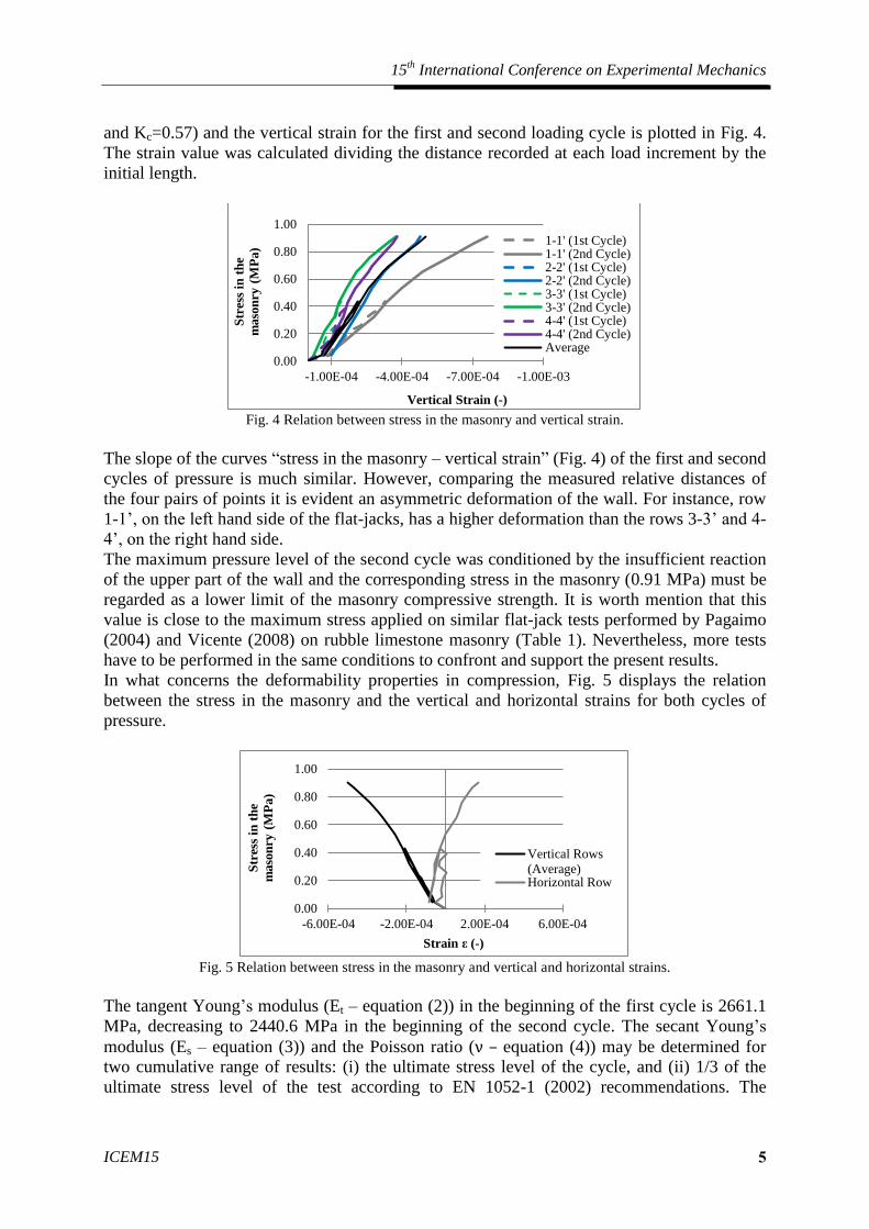
and Kc=0.57) and the vertical strain for the first and second loading cycle is plotted in Fig. 4.
The strain value was calculated dividing the distance recorded at each load increment by the
initial length.
Fig. 4 Relation between stress in the masonry and vertical strain.
The slope of the curves “stress in the masonry – vertical strain” (Fig. 4) of the first and second
cycles of pressure is much similar. However, comparing the measured relative distances of
the four pairs of points it is evident an asymmetric deformation of the wall. For instance, row
1-1’, on the left hand side of the flat-jacks, has a higher deformation than the rows 3-3’ and 4-
4’, on the right hand side.
The maximum pressure level of the second cycle was conditioned by the insufficient reaction
of the upper part of the wall and the corresponding stress in the masonry (0.91 MPa) must be
regarded as a lower limit of the masonry compressive strength. It is worth mention that this
value is close to the maximum stress applied on similar flat-jack tests performed by Pagaimo
(2004) and Vicente (2008) on rubble limestone masonry (Table 1). Nevertheless, more tests
have to be performed in the same conditions to confront and support the present results.
In what concerns the deformability properties in compression, Fig. 5 displays the relation
between the stress in the masonry and the vertical and horizontal strains for both cycles of
pressure.
Fig. 5 Relation between stress in the masonry and vertical and horizontal strains.
The tangent Young’s modulus (Et – equation (2)) in the beginning of the first cycle is 2661.1
MPa, decreasing to 2440.6 MPa in the beginning of the second cycle. The secant Young’s
modulus (Es – equation (3)) and the Poisson ratio (ν – equation (4)) may be determined for
two cumulative range of results: (i) the ultimate stress level of the cycle, and (ii) 1/3 of the
ultimate stress level of the test according to EN 1052-1 (2002) recommendations. The
0.00
0.20
0.40
0.60
0.80
1.00
-1.00E-03-7.00E-04-4.00E-04-1.00E-04
Str
ess
in t
he
maso
nry
(M
Pa)
Vertical Strain (-)
1-1' (1st Cycle)1-1' (2nd Cycle)2-2' (1st Cycle)2-2' (2nd Cycle)3-3' (1st Cycle)3-3' (2nd Cycle)4-4' (1st Cycle)4-4' (2nd Cycle)Average
0.00
0.20
0.40
0.60
0.80
1.00
-6.00E-04 -2.00E-04 2.00E-04 6.00E-04
Str
ess
in t
he
maso
nry
(M
Pa)
Strain ε (-)
Vertical Rows
(Average)Horizontal Row

Porto/Portugal, 22-27 July 2012
Editors: J.F. Silva Gomes and Mário A.P. Vaz 6
obtained values for the secant Young’s modulus and the Poisson ratio vary, respectively,
between (i) 1817.4 MPa and 0.34, (ii) 1684.4 MPa and 0.31.
The values for the secant Young’s modulus are slightly higher than the medium values
proposed by OPCM 2374 (2003) for the same masonry typology (Table 1). However, the
values proposed on the Italian standard cannot be directly used for the calibration of tests
performed on traditional Portuguese masonries. Additional experimental in situ tests have to
be conducted to confront the obtained values.
SHEAR FLAT-JACK TEST
The shear tests were based on the procedure suggested by Caliò (Caliò, 2009) for the test of
brick masonry specimens loaded by the building self-weight. However, in the present work a
vertical stress was applied to the rubble stone masonry specimen by a set of horizontal flat-
jacks. To define the masonry specimen to be tested under shear load, two vertical cuts with a
distance of 35.0 cm were made on the wall. A flat-jack was placed in one of the vertical cuts
while the other remained free. After imposing a vertical compressive stress on both horizontal
flat-jacks, the pressure on the vertical flat-jack is gradually increased. During the test
horizontal and diagonal distances are recorded. The horizontal load applied by the vertical
flat-jack to the masonry (Fh) is obtained from the flat-jack pressure (p), according to (6):
Assuming a Mohr-Coulomb Law for the masonry shear strength and considering that the
vertical stress on the posterior surface of the specimen (Ap) is zero (Caliò, 2009), the
maximum horizontal load (Fh,max) applied by the vertical flat-jack to the masonry is given by
(7):
where As is the area of the horizontal sliding surfaces, τo is the masonry cohesion, µ the
coefficient of friction and σn is the vertical stress applied to the specimen.
Knowing the magnitude of the vertical stress (σn) and the correspondent horizontal maximum
pressure (p) from at least two shear tests, the masonry cohesion (τo) and the coefficient of
friction (µ) can be calculated by equation (7).
SHEAR FLAT-JACK TEST RESULTS
Three shear flat-jack tests were carried out to evaluate the shear strength of the masonry. In
addition to the horizontal force applied, on the first two tests a set of horizontal flat-jacks
impose a vertical compressive stress to the masonry specimen. The third test aimed the
evaluation of the shear strength of the posterior surface of the masonry specimen. In this case,
in addition to the vertical cuts, two horizontal were made on the specimen to release the state
of vertical stress.
SHEAR TEST 1
The test 1 setup is shown in Fig. 6.a. Points A1-A2, A3-A4, B1-B2, B3-B4 are related with
measurements on of the horizontal relative distances and A2-B3, B2-A3 with the diagonal
relative distances. First, the pressure on the horizontal flat-jacks was increased and kept with a
constant value of 0.40 MPa. The pressure on the vertical flat-jack was then gradually
Fh = p x Ke x Kc x Aje (6)
Fh,max = As x (τo + µ x σn) + Ap x τo (7)

15th International Conference on Experimental Mechanics
ICEM15 7
increased until the maximum resistance of the specimen was obtained. The frontal cracks on
the masonry specimen at the end of the test are shown in Fig. 6.b.
a) b)
Fig. 6 Shear Test 1: a) test setup with a vertical pressure of 0.40 MPa (dimensions in cm); b) frontal cracks on
the masonry at the end of the test.
The ratio between the flat-jack pressure and the horizontal and diagonal relative distances of
the masonry specimen is plotted in Fig. 7. The final pressure on the vertical flat-jack was of
3.10 MPa to a maximum horizontal deformation between 2.62 mm (rows A1-A2 and B1-B2)
and 2.13 mm (rows A3-A4 and B3-B4).
Fig. 7 Loading cycle with a vertical pressure of 0.40 MPa.
Converting the pressure on the flat-jacks to stresses in the masonry, the maximum horizontal
stress was 1.03 MPa (Ke=0.71 and Kc=0.47), for a vertical stress of 0.16 MPa (Ke=0.70 and
Kc=0.58). The corresponding maximum horizontal force (equation (6)) is 47.5 kN.
For shear flat-jack tests of brick masonry it is reasonable to assume that the shear failure of
specimen occurs along two horizontal surfaces, coincident with the mortar bed joints, and on
the posterior surface of the masonry specimen (Bosiljkov et al., 2010). However, in rubble
stone masonry specimens, the definition of the sliding surfaces (horizontal and posterior) is
more ambiguous.
At the end of the test, two semi-horizontal cracks were clearly visible on the frontal surface of
the specimen (Fig. 8.a) and on the lateral sides (inside the vertical cuts). On the lateral sides, 3
to 4 cm long cracks were detected on the bottom of the specimen, while on the top a 20 cm
0.00
1.00
2.00
3.00
4.00
-6.00 -4.00 -2.00 0.00 2.00 4.00 6.00
Pre
ssu
re o
n
flat-
jack
p (
MP
a)
Relative Distance (mm)
A1-A2A3-A4B1-B2B3-B4A2-B3B2-A3

Porto/Portugal, 22-27 July 2012
Editors: J.F. Silva Gomes and Mário A.P. Vaz 8
long crack was visible on the left side (Fig. 8.b) and a 9 cm long crack on the right side (Fig.
8.c). However, its propagation inside the masonry specimen is undetermined.
a) b) c)
Fig. 8 Shear failure: a) frontal cracks and details from the top crack inside the vertical cuts; b) left lateral crack
and; c) right lateral crack (dimensions in cm).
In order to define the area of the sliding surfaces, the horizontal surfaces may consider the
frontal cracks visible on the masonry (Fig. 8.a) and accept that these cracks propagate inside
the specimen according with two different options. The first option assumes a propagation
length of 11 cm corresponding to the length of the rectangular part of the semi-circular flat-
jacks (Fig. 2), in which the masonry specimen is presumed to be under uniform stress state
(vertical and horizontal). The second considers a propagation length of 21 cm considering the
area of the flat-jack (Aj=75200 mm2) divided by the distance between the vertical cuts (equal
to 35 cm). The imprecision is significant, but the first option is expected to be less
conservative as the underestimation of the area of the failure surface leads to the
overestimation of the shear strength parameters.
The posterior vertical sliding surface is assumed to be the plane surface that connects both
horizontal sliding surfaces. The sliding surface failure is depicted in Fig. 9 along with the area
of the surfaces for both options.
Surface Area Option 1
L = 11 cm
Option 2
L = 21 cm
Assuperior
48785 mm2 93135 mm
2
Asinferior
52437 mm2 100107 mm
2
Ap 91651 mm2 91651 mm
2
Fig. 9 Test 1 failure surfaces.
SHEAR TEST 2
On the second shear test, a pressure of 0.60 MPa was applied to the horizontal flat-jacks. The
test 2 setup is shown in Fig. 10.a. Like before, points A1-A2, A3-A4, B1-B2, B3-B4 are
related with horizontal relative distances and A2-B3, B2-A3 with diagonal relative distances.
Fig. 10.b shows the frontal cracks on the masonry specimen at the end of the test. The
masonry that offers reaction to the vertical flat-jack also suffered a local crush, which
L

15th International Conference on Experimental Mechanics
ICEM15 9
conditioned the pressurization of the flat-jack and, probably induced the premature conclusion
of the test (with a final pressure on the flat-jack of 2.92 MPa). This premature failure may
explain the fact that the maximum horizontal pressure applied on the flat-jack is lower than
the maximum horizontal pressure applied on test 1, where a lower vertical stress was imposed
to the specimen.
a) b)
Fig. 10 Shear Test 2: a) test setup with a vertical pressure of 0.60 MPa (dimensions in cm); b) frontal cracks on
the masonry at the end of the test.
The ratio between the flat-jack pressure and the horizontal and diagonal relative distances of
the masonry specimen is described in Fig. 11. In this test the masonry specimen experienced a
great horizontal deformation, which ended up exceeding, on rows A1-A2 and B1-B2, the
range of the mechanical gauge in use. The final horizontal deformation was between 4.96 mm
(rows A1-A2 and B1-B2) and 2.80 mm (rows A3-A4 and B3-B4).
Fig. 11 Loading cycle with a vertical pressure of 0.60 MPa.
The results from test 2 were also influenced by the accumulated deformation of the masonry
specimen due to a previous loading. The second test was previously performed, but
uncompleted in consequence of the flat-jack’s weld throat rupture. In addition, and as
mentioned before, during the test the masonry against which the vertical flat-jack reacted
suffered a local crush (Fig. 10.b), which conditioned the pressurization of the vertical flat-
jack. The shear failure occurred for a horizontal stress on masonry of 1.07 MPa (Ke=0.73 and
0.00
1.00
2.00
3.00
4.00
-6.00 -4.00 -2.00 0.00 2.00 4.00 6.00
Pre
ssu
re o
n
flat-
jack
p (
MP
a)
Relative Distance (mm)
A1-A2A3-A4B1-B2B3-B4A2-B3B2-A3

Porto/Portugal, 22-27 July 2012
Editors: J.F. Silva Gomes and Mário A.P. Vaz 10
Kc=0.50), when the specimen was under a vertical stress of 0.24 MPa (Ke=0.70 and Kc=0.57).
The corresponding maximum horizontal force (equation (6)) was 52.6 kN. Though, it is
important to refer that the results from the shear test 2 are not completely reliable in
consequence of the incomplete test previously performed.
At the end of the test, cracks were visible on the frontal surface (Fig. 10.b) and on the lateral
side of the masonry specimen (inside the vertical cuts). On lateral surfaces, approximately 2
to 3 cm long cracks were visible on the bottom of the specimen and 6 cm long cracks on the
top. Once more, the test was stopped before the effective sliding of the masonry specimen and
the definition of the cracked surface is ambiguous. The sliding surfaces were defined
assuming the same hypothesis referred for test 1, as presented in Fig. 12.
Surface Area Option 1
L = 11 cm
Option 2
L = 21 cm
Assuperior
38954 mm2 74367 mm
2
Asinferior
38005 mm2 72555 mm
2
Ap 116708 mm2 116708 mm
2
Fig. 12 Test 2 failure surfaces.
SHEAR TEST 3
The last shear test was performed on a specimen already tested by double flat-jack vertical
loading; hence the specimen size differs from the test setup 1 and 2. Two vertical cuts were
made adjacent to the already existing horizontal cuts, defining a specimen approximately 40
cm high with a 40 cm width, connected to the masonry wall only on the posterior surface. The
test setup is shown in Fig. 13, as well as the gage point’s position. The rows A1-A2, A3-A4,
B1-B2, B3-B4 are related with horizontal relative distances and A2-B5, A5-B2 with diagonal
relative distances. A flat-jack was placed on the left vertical cut, while the right vertical cut
remained free for the specimen horizontal deformation (Fig. 13).
Fig. 13 Shear flat-jack test setup and gage point’s position (dimensions in cm).
The relation between the flat-jack pressure and the horizontal and diagonal relative distances
on the masonry specimen is described in Fig. 14. Due to the boundary conditions, it was
L

15th International Conference on Experimental Mechanics
ICEM15 11
impossible to observe the cracked surface of the wall (frontal and lateral). The test was
stopped with a final pressure on the flat-jack of 2.18 MPa, as the support was not offering
enough reaction to proceed with the test.
Fig. 14 Loading cycle without vertical pressure.
The final deformation was between 1.92 mm (rows A1-A2 and B1-B2) and 0.46 mm (rows
A3-A4 and B3-B4), a variation that cannot be ignored. In fact, considering both the distances
measured on the horizontal row B3-B4 and on the diagonal row A2-B5, it seems that the
masonry specimen was under in plane rotation (clockwise direction). Nevertheless, it will be
assumed that the shear failure occurred on the connection between the posterior part of the
specimen and the wall (Ap = 1600 mm2). The maximum pressure applied by the flat-jack was
2.18 MPa, which corresponds to a horizontal stress on the masonry of 0.74 MPa (Ke=0.64 and
Kc=0.53) and maximum horizontal force of 33.8 kN. Considering the assumed shear failure,
the shear strength of the posterior surface is 0.21 MPa.
DISCUSSION OF THE SHEAR TESTS RESULTS
Several tests were carried out in the laboratory to assess the shear strength parameters of
traditional rubble stone masonry (Milošević et al., 2011) (Milošević et al., 2012). The
masonry panels were built with the same materials (limestone and lime mortars) and
techniques used in traditional construction and subjected to diagonal compression tests and
triplet tests (Table 2).
Table 2 Masonry Shear Strength Parameters (literature results).
Type of Test Cohesion τ0
(MPa)
Coefficient of
friction µ
Milošević et al.
(2011)
Triplet Tests on limestone rubble masonry and air
lime mortar specimens 0.0815 0.558
Diagonal Compression Tests on limestone rubble
masonry and air lime mortar specimens 0.024 --
OPCM 3274
(2003)
Table 11.D.1 – Irregular stone masonry (pebbles,
erratic and irregular stone) 0.020 – 0.032 0.40
(Characteristic
value) Table 11.D.1 – Uncut stone masonry with facing
walls of limited thickness and infill core 0.035 – 0.051
From the diagonal compression tests on masonry and air lime mortar specimens it was
obtained for the cohesion a value of 0.024 MPa. From the triplet tests on masonry and air lime
0.00
1.00
2.00
3.00
4.00
-6.00 -4.00 -2.00 0.00 2.00 4.00 6.00
Pre
ssu
re o
n
flat-
jack
p (
MP
a)
Relative Distance (mm)
A1-A2A3-A4B1-B2B3-B4A2-B5B2-A5

Porto/Portugal, 22-27 July 2012
Editors: J.F. Silva Gomes and Mário A.P. Vaz 12
mortar specimens it was obtained for the cohesion a value of 0.0815 MPa and a coefficient of
friction of 0.558.
Despite the fact that Portuguese masonries do not exactly fit the Italian masonry typologies
and a regional influence on the technics and materials may have an important influence, the
values proposed by the OPCM 3274 (2003) can be used as indicative values (Table 2). For
masonry typologies that may be related with the present masonry the standard OPCM 3274
(2003) indicates cohesion values between 0.020 MPa and 0.051 MPa and a (characteristic)
value of 0.40 for the coefficient of friction.
Considering the shear surfaces based on the options depicted in Fig. 9 and Fig. 12,
respectively for test 1 and 2, values for the shear parameters (cohesion and coefficient of
friction) obtained with equation (7) are significantly different from the expected, particularly
the coefficient of friction which resulted greater than 1.0 (Table 3).
Table 3 Shear strength parameters (test 1 and 2).
Surface Area Option 1
L = 11 cm
Option 2
L = 21 cm
Cohesion τ0 (MPa) 0.060 0.026
Coefficient of friction µ 2.22 1.30
The shear test 3 aimed the determination of the shear strength of the posterior surface of the
specimen, which is possibly related to the masonry cohesion. In this test, the obtained shear
strength was 0.21 MPa, which is much higher than the referred values for the masonry
cohesion (Table 2).
In fact, if the results from test 1 and 2 (considering the conservative option of the 21 cm
uniform propagation) are affected by 0.21 MPa stress on the posterior failure surface, the
shear strength on the horizontal failure surfaces is lower than the shear strength of the
posterior surface. Assuming a Mohr-Coulomb Law for the masonry shear strength and
considering that the vertical stress on the posterior surface of the specimen (Ap) is zero (Caliò,
2009), this result cannot be correct (the coefficient of friction is a positive value).
If in one hand, the results from test 2 are not completely reliable, as well as the definition of
the shear failure surfaces (horizontal and posterior), on the other hand, test 3 indicated that the
posterior surface of the specimen has an influence on the shear strength that may be higher
than in reality.
These results may derive from the uncertainties in the definition of the failure surface and of
the heterogeneity of the materials, which may lead to an above normal resistance in a surface
across a major stone or to a change in the failure surface. Therefore more data is necessary for
comparison, to allow the identification of those types of situations and to purge
unreliable/unrepresentative results. It can thus be concluded that the experimental campaign
herein presented shows the need of performing more shear tests in rubble stone masonry walls
with the similar boundary conditions in order to calibrate the test procedure and to get
satisfactory correlating factors.
CONCLUSION
The flat-jack tests provide a relatively non-destructive technique to assess the in situ
mechanical properties of masonry walls. This testing technique has been successfully used in
regular brick and stone masonry structures, but its practice on rubble stone masonry structures
is not so common.

15th International Conference on Experimental Mechanics
ICEM15 13
From the compressive flat-jack tests experimental acceptable values were obtained for the
secant Young’s modulus (between 1684.4 MPa and 1817.4 MPa) and for the Poisson ratio
(between 0.31 and 0.34). The maximum compressive stress applied to the masonry specimen
(0.91 MPa) is also compatible with the maximum compressive stresses referred on the
literature regarding flat-jack tests.
As to the shear strength parameters, considerable deviations from the reference values were
obtained in this experimental campaign. As mentioned, the boundary conditions of the
specimen and the high heterogeneity of the material had a great influence on the results.
The existent standards concerning shear tests with flat-jacks (ASTM C 1531-03 (2003) and
RILEM MS-D.6 (1996)) were developed for regular block masonry where the cuts cross the
entire thickness of the wall, completely isolating the specimens from the remaining masonry.
The great thickness of the traditional masonry walls implies on boundary conditions which
have a major influence on the test results. Further studies have to be conducted to define the
necessary calibration parameters.
ACKNOWLEDGMENTS
The authors would like to thank Engineer Vasco Appleton from A2P, Lda and Architect
Fernando Gaio from Assimec, S.A. for providing access to the building where this
experimental campaign took place. The authors would also like to acknowledge the financial
support of the Portuguese Foundation for Science and Technology (Ministry of Science and
Technology of the Republic of Portugal) through the research project
PTDC/ECM/100872/2008 named ‘Seismic Vulnerability of Old Masonry Buildings’.
REFERENCES
(ASTM C 1197-04, 2004) ASTM C 1197-04 – Standard Test Method for in situ measurement
of masonry deformability properties using the flatjack method. ASTM International, West
Conshohocken, USA, 2004.
(ASTM C 1531-03, 2003) ASTM C 1531-03 – Standard Test Method for in situ measurement
of masonry mortar joint shear strength index. ASTM International, West Conshohocken,
USA, 2003.
(Binda & Tiraboschi, 1999) Binda, L.; Tiraboschi, C. – Flat-Jack Test: A slightly destructive
technique for the diagnosis of brick and stone masonry structures. Restoration of Buildings
and Monuments International Journal, Issue 5, p. 449-472, 1999.
(Bosiljkov et al., 2010) Bosiljkov, V.; Bokan-Bosiljkov, V.; Strah, B.; Velkavrh, J.; Cotič –
Deliverable D6: Review of innovative techniques for the knowledge of cultural assets.
Perpetuate Project, 2010.
(Caliò, 2009) Caliò, I. – La Prova di Scorrimento con Matinetto Piatto: Specifiche di Prova -
Allegato 3b.3-UR14-1. Rete dei Laboratori Universitari di Ingegneria Sismica (RELUIS),
Progetto di ricerca N.1: Valutazione e Riduzione della Vulnerabilità di Edifici in Muratura,
Rendicontazione Scientifica 3º anno, March 2009 (in Italian).
(Cardoso et al., 2005) Cardoso, R.; Lopes, M.; Bento, R. – Seismic evaluation of old masonry
buildings. Part I: Method description and application to a case-study. Engineering Structures
27, 2005, pp. 2024-2035.
(EN 1052-1:1998) EN 1052-1:1998 – Methods of test for masonry – Part 1: Determination of
compressive strength. European Committee for Standardization (CEN), September 1998.
(INE, 2002) Instituto Nacional de Estatísticas (INE) – Census of housing and population –
Census 2001 (Original Title: Recenseamento da população e da habitação (Portugal) –
Porto/Portugal, 22-27 July 2012
Editors: J.F. Silva Gomes and Mário A.P. Vaz 14
Censos 2001). Instituto Nacional de Estatísticas (INE), 2002, Lisbon, Portugal (in
Portuguese).
(Milošević et al., 2012) Milošević, J.; Gago, A.; Bento, R.; Lopes, M. – Experimental
Evaluation of the Shear Strength of Masonry Walls. Proceedings of the 15th
International
Conference on Experimental Mechanics, pp. 3023, Porto, July 2012.
(Milošević et al., 2011) Milošević, J.; Bento, R.; Gago, A.; Lopes, M. – Report 2:
Experimental Results. SEVERES Project, December 2011.
(OPCM 3274, 2003) OPCM 3274 – Ordinanza n. 3274 del 20/03/2003 – Primi elementi in
material di criteri generali per la classificazione sismica del territorio nazionale e di
normative tecniche per le costruzioni in zona sismica. Allegato 2 – Norme tecniche per il
progetto, la valutazione e l’adeguamento sismico degli edifice. Presidenza del Consiglio dei
Ministri d’Italia.
(Pagaimo, 2004) Pagaimo, F. – Morphological and Mechanical Characterization of Ancient
Masonry. Study of the Historic Village of Tentúgal (Original Title: Caracterização
Morfológica e Mecânica de Alvenarias Antigas. Caso de Estudo da Vila Histórica de
Tentúgal). M.Sc. Thesis in Engenharia Civil - Estruturas, Faculdade de Ciências e
Tecnologia, Universidade de Coimbra, November 2004, Portugal (in Portuguese).
(Ravara et al., 2001) Ravara, A.; Oliveira, C. S.; Carvalho, E. C.; Lopes, M.; Costa, P.;
Delgado, R.; Bairrão, R.; Silva, V. C. – Reducing the seismic vulnerability of the building
stock. Sociedade Portuguesa de Engenharia Sísmica (SPES) and Grémio das Empresas de
Conservação e Restauro do Património Arquitectónico (GECoRPA), Ordem dos Engenheiros,
April 2001, Lisbon, Portugal.
(RILEM MDT.D.5, 2004) RILEM MDT.D.5 – In-situ stress-strain behaviour tests based on
the flat jack. RILEM TC 177-MDT: Masonry durability and on-site testing. Materials and
Structures, Volume 37, August-September 2004, pp. 497-501.
(RILEM MS-D.6, 1996) RILEM MS-D.6 – In situ measurement of masonry bed joint shear
strength. RILEM TC 127-MS: Tests form masonry materials and structures, Volume 29,
October 1996, pp. 459-475.
(Roque, 2002) Roque, J. – Structural Rehabilitation of Old Masonry Walls (Original Title:
Reabilitação Estrutural de Paredes Antigas de Alvenaria). M.Sc. Thesis in Engenharia Civil,
Universidade do Minho, September 2002, Portugal (in Portuguese).
(Vicente, 2008) Vicente, R. – Strategies and methodologies for the urban rehabilitation.
Assessment of the vulnerability and seismic hazard of the buildings from the Coimbra historic
centre (Original Title: Estratégias e metodologias para intervenções de reabilitação urbana.
Avaliação da vulnerabilidade e do risco sísmico do edificado da Baixa de Coimbra). Phd
Thesis in Engenharia Civil, Universidade de Aveiro, 2008, Portugal (in Portuguese).