flashblox: achieving both performance isolation and … achieving both performance isolation and...
TRANSCRIPT

This paper is included in the Proceedings of the 15th USENIX Conference on
File and Storage Technologies (FAST ’17).February 27–March 2, 2017 • Santa Clara, CA, USA
ISBN 978-1-931971-36-2
Open access to the Proceedings of the 15th USENIX Conference on File and Storage Technologies
is sponsored by USENIX.
FlashBlox: Achieving Both Performance Isolation and Uniform Lifetime for Virtualized SSDs
Jian Huang, Georgia Institute of Technology; Anirudh Badam, Laura Caulfield, Suman Nath, Sudipta Sengupta, and Bikash Sharma, Microsoft; Moinuddin K. Qureshi,
Georgia Institute of Technology
https://www.usenix.org/conference/fast17/technical-sessions/presentation/huang

FlashBlox: Achieving Both Performance Isolationand Uniform Lifetime for Virtualized SSDs
Jian Huang† Anirudh Badam Laura Caulfield
Suman Nath Sudipta Sengupta Bikash Sharma Moinuddin K.Qureshi†
†Georgia Institute of Technology Microsoft
AbstractA longstanding goal of SSD virtualization has been toprovide performance isolation between multiple tenantssharing the device. Virtualizing SSDs, however, has tra-ditionally been a challenge because of the fundamentaltussle between resource isolation and the lifetime of thedevice – existing SSDs aim to uniformly age all the re-gions of flash and this hurts isolation. We propose uti-lizing flash parallelism to improve isolation between vir-tual SSDs by running them on dedicated channels anddies. Furthermore, we offer a complete solution by alsomanaging the wear. We propose allowing the wear of dif-ferent channels and dies to diverge at fine time granular-ities in favor of isolation and adjusting that imbalance ata coarse time granularity in a principled manner. Our ex-periments show that the new SSD wears uniformly whilethe 99th percentile latencies of storage operations in avariety of multi-tenant settings are reduced by up to 3.1xcompared to software isolated virtual SSDs.
1 IntroductionSSDs have become indispensable for large-scale cloudservices as their cost is fast approaching to that of HDDs.They out-perform HDDs by orders of magnitude, provid-ing up to 5000x more IOPS, at 1% of the latency [21].The rapidly shrinking process technology has allowedSSDs to boost their bandwidth and capacity by increas-ing the number of chips. However, the limitations ofSSDs’ management algorithms have hindered these par-allelism trends from efficiently supporting multiple ten-ants on the same SSD.
Tail latency of SSDs in multi-tenant settings is onesuch limitation. Cloud storage and database systemshave started colocating multiple tenants on the sameSSDs [14, 58, 79] which further exacerbates the alreadywell known tail latency problem of SSDs [25, 26, 60, 78].
The cause of tail latency is the set of complex flashmanagement algorithms in the SSD’s controller, calledthe Flash Translation Layer (FTL). The fundamentalgoals of these algorithms are decades-old and were
meant for an age when SSDs had limited capacity and lit-tle parallelism. The goals were meant to hide the idiosyn-crasies of flash behind a layer of indirection and exposea block interface. These algorithms, however, conflatewear leveling (to address flash’s limited lifetime) and re-source utilization (to exploit parallelism) which increasesinterference between tenants sharing an SSD.
While application-level flash-awareness [31, 36, 37,51, 75] improves throughput by efficiently leveraging thedevice level parallelism, these optimizations do not di-rectly help reduce the interference between multiple ten-ants sharing an SSD. These tenants cannot effectivelyleverage flash parallelism for isolation even when theyare individually flash-friendly because FTLs hide theparallelism. Newer SSD interfaces [38, 49] that pro-pose exposing raw parallelism directly to higher layersprovide more flexibility in obtaining isolation for tenantsbut they complicate the implementation of wear-levelingmechanisms across the different units of parallelism.
In this work, we propose leveraging the inherent par-allelism present in today’s SSDs to increase isolation be-tween multiple tenants sharing an SSD. We propose cre-ating virtual SSDs that are pinned to a dedicated num-ber of channels and dies depending on the capacity andperformance needs of the tenant. The fact that the chan-nels and dies can be more or less operated upon indepen-dently helps such virtual SSDs avoid adverse impacts oneach other’s performance. However, different workloadscan write at different rates and in different patterns, thiscould age the channels and dies at different rates. Forinstance, a channel pinned to a TPC-C database instancewears out 12x faster than a channel pinned to a TPC-E database instance, reducing the SSD lifetime dramat-ically. This non-uniform aging creates an unpredictableSSD lifetime behavior that complicates both provision-ing and load-balancing aspects of data center clusters.
To address this problem, we propose a two-part wear-leveling model which balances wear within each virtualSSD and across virtual SSDs using separate strategies.Intra-virtual SSD wear is managed by leveraging exist-ing SSD wear-balancing mechanisms while inter-virtual
USENIX Association 15th USENIX Conference on File and Storage Technologies 375

100 105 110 115 120 125
Time (seconds)
0100200300400500600700
Ban
dwid
th (M
B/s
ec)
Instance-1-readInstance-2-writeInstance-3-read
Instance-4-write
(a) Software Isolated Instances
100 105 110 115 120 125
Time (seconds)
0100200300400500600700
Ban
dwid
th (M
B/s
ec)
Instance-1-readInstance-2-writeInstance-3-read
Instance-4-write
(b) Hardware Isolated Instances
SoftwareIsolated
HardwareIsolated
05
1015202530354045
Late
ncy
(mill
isec
s) Instance-1-readInstance-2-writeInstance-3-readInstance-4-write
(c) 99th Percentile Latency
SoftwareIsolated
HardwareIsolated
0
5
10
15
20
Avg.
Num
ber
of B
lock
sE
rase
d Pe
r Se
cond CH-1
CH-2CH-3CH-4
CH-5CH-6CH-7CH-8
(d) Wear Leveling
Figure 1: Tenants sharing an SSD get better bandwidth (compare (a) vs. (b)) and tail latency as shown in (c) whenusing new hardware isolation. However, dedicating channels to tenants can lead to wear-imbalance between the variouschannels as shown in (d). Note that the number of blocks erased in the first, fourth and fifth channels is close to zerobecause they host workloads with only read operations. This imbalance of write bandwidth across different workloadscreates wear-imbalance across channels. A new design for addressing such a wear-imbalance is proposed in this paper.
SSD wear is balanced at coarse-time granularities to re-duce interference by using new mechanisms. We con-trol the wear imbalance between virtual SSDs using amathematical model and show that the new wear-levelingmodel ensures near-ideal lifetime for the SSD with neg-ligible disruption to tenants. More specifically, this workmakes the following contributions:
• We present a system named FlashBlox using whichtenants can share an SSD with minimal interferenceby working on dedicated channels and dies.
• We present a new wear-leveling mechanism that al-lows measured amounts of wear imbalance to obtainbetter performance isolation between such tenants.
• We present an analytical model and a system thatcontrol the wear imbalance between channels anddies, so that they age uniformly with negligible in-terruption to the tenants.
We design and implement FlashBlox and its new wear-leveling mechanisms inside an open-channel SSD stack(from CNEX labs [18]), and demonstrate benefits for aMicrosoft data centers’ multi-tenant storage workloads:the new SSD delivers up to 1.6x better throughput andreduces the 99th percentile latency by up to 3.1x. Fur-thermore, our wear leveling mechanism provides 95% ofthe ideal SSD lifetime even in the presence of adversar-ial write workloads that execute all the writes on a singlechannel while only reading on other channels.
The rest of this paper is organized as follows: § 2presents the challenges that we address in this work. De-sign and implementation of FlashBlox are described in§ 3. Evaluation results are shown in § 4. § 5 presents therelated work. We present the conclusions in § 6.
2 SSD Virtualization: Opportunityand Challenges
Premium storage Infrastructure-as-a-Service (IaaS) of-ferings [4, 7, 22], persistent Platform-as-a-Service(PaaS) systems [8] and Database-as-a-Service (DaaS)systems [2, 5, 9, 23] need SSDs to meet their servicelevel objectives (SLO) that are usually outside the scope
of HDD performance. For example, DocDB [5] guaran-tees 250, 1,000 and 2,500 queries per second respectivelyfor the S1, S2 and S3 offerings [6].
Storage virtualization helps such services make effi-cient use of SSDs’ high capacity and performance byslicing resources among multiple customers or instances.Typical database instances in DaaS systems are 10 GB –1 TB [6, 10] whereas each server can have more than 20TB of SSD capacity today.
Bandwidth, IOPS [48, 56] or a convex combinationof both [57, 74] is limited on a per-instance basis usingtoken bucket rate limiters or intelligent IO throttling [41,59, 66] to meet SLOs. However, there is no analogousmechanism for sharing the SSD while maintaining lowIO tail latency – an instance’s latency still depends onthe foreground reads/writes [25, 42, 73] and backgroundgarbage collection [34] of other instances.
Moreover, it is becoming increasingly necessary to co-locate diverse workloads (e.g. latency-critical applica-tions and batch processing jobs), to improve resource uti-lization, while maintaining isolation [33, 42]. Virtualiza-tion and container technologies are evolving to exploithardware isolation of memory [11, 47], CPU [16, 40],caches [28, 52], and networks [30, 72] to support suchscenarios. We extend this line of research to SSDs byproviding hardware-isolated SSDs, complete with a so-lution for the wear-imbalance problem that arises due tothe physical flash partitioning across tenants with diverseworkloads.
2.1 Hardware Isolation vs. Wear-LevelingTo understand this problem, we compare the two differ-ent approaches to sharing hardware. The first approachstripes data from all the workloads across all the flashchannels (eight total), just as existing SSDs do. Thisscheme provides the maximum throughput for each IO,and uses the software rate limiter which has been usedfor Linux containers and Docker [12, 13] to implementweighted fair sharing of the resources (the scenario forFigure 1(a)). Note that instances in the software-isolatedcase do not share physical flash blocks with other colo-cated instances. This eliminates the interference due to
376 15th USENIX Conference on File and Storage Technologies USENIX Association

FlashChannel
Die
Plane
…
Plane
Die
Plane
…
Plane
……
Channel
Die
Plane
…
Plane
Die
Plane
…
Plane
…………
Figure 2: SSD Architecture: Internal parallelism in SSDscreates opportunities for hardware-level isolation.
garbage collection in one instance affecting another in-stance’s read performance [34]. The second approachuses a configuration from our proposed mechanism thatprovides the hardware isolation by assigning a certainnumber of channels to each instance (the scenario forFigure 1(b)).
In both scenarios, there are four IO-intensive work-loads. These workloads request 1/8th, 1/4th, 1/4th and3/8th of the shared storage resource. The rate limiteruses these as weights in the first approach, while Flash-Blox assigns 1, 2, 2 and 3 channels respectively. Work-loads 2 and 4 perform 100% writes and workloads 1 and3 perform 100% reads. All workloads issue sequentially-addressed and aligned 64 KB IOs.
Hardware isolation not only reduces the 99th per-centile latencies by up to 1.7x (Figure 1(c)), but also in-creases the aggregate throughput by up to 10.8% com-pared to software isolation. However, pinning instancesto channels prevents the hardware from automaticallyleveling the wear across all the channels, as shown inFigure 1(d). We exaggerate the variance of write ratesto better motivate the problem of wear-imbalance thatstems from hardware-isolation of virtual SSDs. Later inthe paper, we will use applications’ typical write rates(see Figure 5) to design our final solution. To moti-vate the problem further, we must first explore the par-allelism available in SSD hardware, and the aspects ofFTLs which cause interference in the first approach.
2.2 Leveraging Parallelism for IsolationTypical SSDs organize their flash array into a hierar-chy of channels, dies, planes, blocks and pages [1, 17].As shown in Figure 2, each SSD has multiple channels,each channel has multiple dies, and each die has mul-tiple planes. The number of channels, dies and planesvaries by vendor and generation. Typically, there are 2 -4 planes per die, 4 - 8 dies per channel, and 8 - 32 chan-nels per drive. Each plane is composed of thousands ofblocks (typically 4-9MB) and each block contains 128-256 pages.
This architecture plays an important role in definingisolation boundaries. Channels, which share only the re-sources common to the whole SSD, provide the strongestisolation. Dies execute their commands with completeindependence, but they must share a bus with other dieson the same channel. Planes’ isolation is limited becausethe die contains only one address buffer. The controller
may isolate data to different planes, but operations onthese data must happen at different times or to the sameaddress on each plane in a die [32].
In current drives, none of this flexibility is exposed tothe host. Drives instead optimize for a single IO pat-tern: extremely large or sequential IO. The FTL logicallygroups all planes into one large unit, creating “super-pages” and “super-blocks” are hundreds of times largerthan their base unit. For example, a drive with 4MBblocks and 256 planes has a 1GB super-block.
Striping increases the throughput of large, sequentialIOs, but introduces the negative side effect of interfer-ence between multiple tenants sharing the drive. As alldata is striped, every tenant’s reads, writes and erases canpotentially conflict with every other tenant’s operations.
Previous work had proposed novel techniques to helptenants place their data such that underlying flash pagesare allocated from separate blocks. This helps improveperformance by reducing the write amplification factor(WAF) [34]. Lack of block sharing has the desirable sideeffect of clumping garbage into fewer blocks, leading tomore efficient garbage collection (GC), thereby reducingtail latency of SSDs [25, 42, 43, 73].
However, significant interference still exists betweentenants because when data is striped, every tenant usesevery channel, die and plane for storing data and thestorage operations of one tenant can delay other tenants.Software isolation techniques [57, 67, 68] split the theSSD’s resources fairly. However, they cannot maximallyutilize the flash parallelism when resource contention ex-ists at a layer below because of the forced sharing of in-dependent resources such as channels, dies and planes.
New SSD designs, such as open-channel SSDs that ex-plicitly expose channels, dies and planes to the operatingsystem [44, 38, 49], can help tenants who share an SSDavoid some of these pitfalls by using dedicated channels.However, the wear imbalance problem between chan-nels that ensues from different tenants writing at differentrates remains unsolved. We propose a holistic approachto solve this problem by exposing flash channels and diesas virtual SSDs, while the system underneath wear-levelswithin each vSSD and balances the wear across channelsand dies at coarse time granularities.
FlashBlox is concerned only with sharing of the re-sources within a single NVMe SSD. Fair sharing mech-anisms that split PCIe bus bandwidth across multipleNVMe devices, network interface cards, graphic pro-cessing units and other PCIe devices is beyond the scopeof this work.
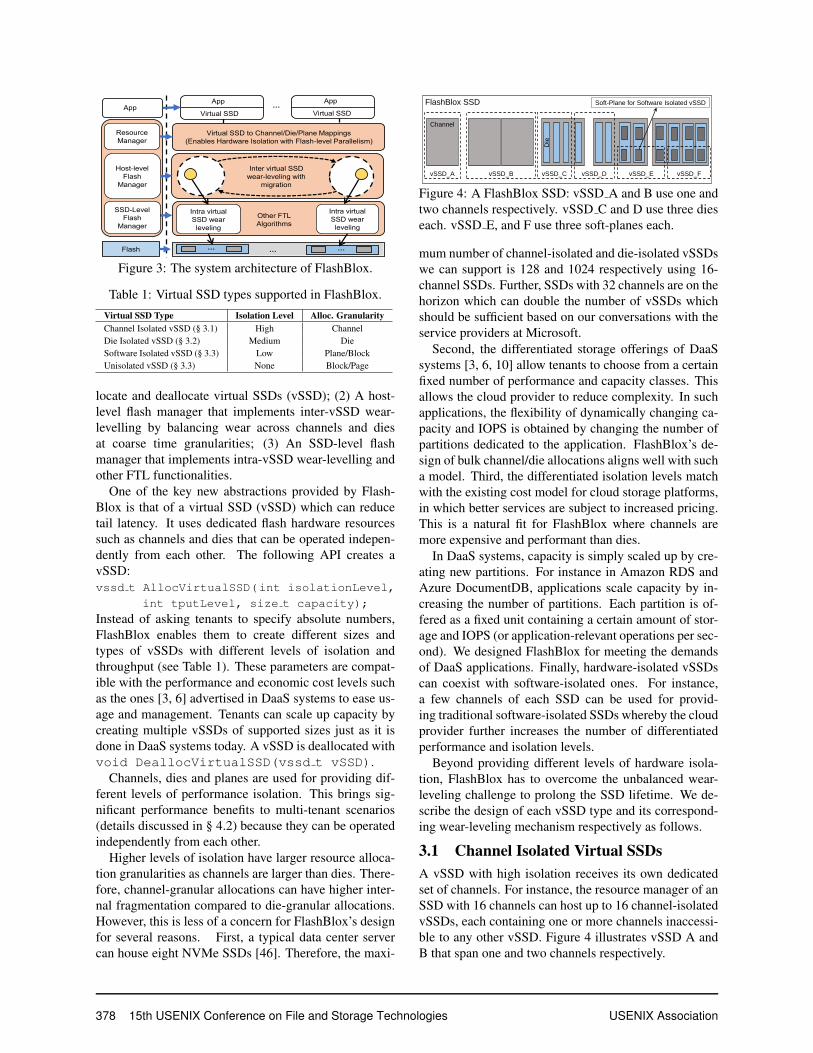
3 Design and ImplementationFigure 3 shows the FlashBlox architecture. At a highlevel, FlashBlox consists of the following three compo-nents: (1) A resource manager that allows tenants to al-
USENIX Association 15th USENIX Conference on File and Storage Technologies 377
App
Virtual SSD
Intra virtual
SSD wear
leveling
Intra virtual
SSD wear
leveling
… …
App
Host-level
Flash
Manager
Flash
App
Virtual SSD
Virtual SSD to Channel/Die/Plane Mappings
(Enables Hardware Isolation with Flash-level Parallelism)
Resource
Manager
…
SSD-Level
Flash
Manager
Inter virtual SSD
wear-leveling with
migration
Other FTL
Algorithms
…
Figure 3: The system architecture of FlashBlox.
Table 1: Virtual SSD types supported in FlashBlox.Virtual SSD Type Isolation Level Alloc. GranularityChannel Isolated vSSD (§ 3.1) High ChannelDie Isolated vSSD (§ 3.2) Medium DieSoftware Isolated vSSD (§ 3.3) Low Plane/BlockUnisolated vSSD (§ 3.3) None Block/Page
locate and deallocate virtual SSDs (vSSD); (2) A host-level flash manager that implements inter-vSSD wear-levelling by balancing wear across channels and diesat coarse time granularities; (3) An SSD-level flashmanager that implements intra-vSSD wear-levelling andother FTL functionalities.
One of the key new abstractions provided by Flash-Blox is that of a virtual SSD (vSSD) which can reducetail latency. It uses dedicated flash hardware resourcessuch as channels and dies that can be operated indepen-dently from each other. The following API creates avSSD:vssd t AllocVirtualSSD(int isolationLevel,
int tputLevel, size t capacity);
Instead of asking tenants to specify absolute numbers,FlashBlox enables them to create different sizes andtypes of vSSDs with different levels of isolation andthroughput (see Table 1). These parameters are compat-ible with the performance and economic cost levels suchas the ones [3, 6] advertised in DaaS systems to ease us-age and management. Tenants can scale up capacity bycreating multiple vSSDs of supported sizes just as it isdone in DaaS systems today. A vSSD is deallocated withvoid DeallocVirtualSSD(vssd t vSSD).
Channels, dies and planes are used for providing dif-ferent levels of performance isolation. This brings sig-nificant performance benefits to multi-tenant scenarios(details discussed in § 4.2) because they can be operatedindependently from each other.
Higher levels of isolation have larger resource alloca-tion granularities as channels are larger than dies. There-fore, channel-granular allocations can have higher inter-nal fragmentation compared to die-granular allocations.However, this is less of a concern for FlashBlox’s designfor several reasons. First, a typical data center servercan house eight NVMe SSDs [46]. Therefore, the maxi-
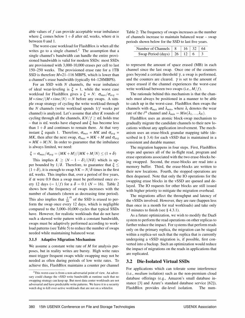
FlashBlox SSD
Channel
vSSD_A vSSD_B
Die
vSSD_C vSSD_D vSSD_E vSSD_F
Soft-Plane for Software Isolated vSSD
Figure 4: A FlashBlox SSD: vSSD A and B use one andtwo channels respectively. vSSD C and D use three dieseach. vSSD E, and F use three soft-planes each.
mum number of channel-isolated and die-isolated vSSDswe can support is 128 and 1024 respectively using 16-channel SSDs. Further, SSDs with 32 channels are on thehorizon which can double the number of vSSDs whichshould be sufficient based on our conversations with theservice providers at Microsoft.
Second, the differentiated storage offerings of DaaSsystems [3, 6, 10] allow tenants to choose from a certainfixed number of performance and capacity classes. Thisallows the cloud provider to reduce complexity. In suchapplications, the flexibility of dynamically changing ca-pacity and IOPS is obtained by changing the number ofpartitions dedicated to the application. FlashBlox’s de-sign of bulk channel/die allocations aligns well with sucha model. Third, the differentiated isolation levels matchwith the existing cost model for cloud storage platforms,in which better services are subject to increased pricing.This is a natural fit for FlashBlox where channels aremore expensive and performant than dies.
In DaaS systems, capacity is simply scaled up by cre-ating new partitions. For instance in Amazon RDS andAzure DocumentDB, applications scale capacity by in-creasing the number of partitions. Each partition is of-fered as a fixed unit containing a certain amount of stor-age and IOPS (or application-relevant operations per sec-ond). We designed FlashBlox for meeting the demandsof DaaS applications. Finally, hardware-isolated vSSDscan coexist with software-isolated ones. For instance,a few channels of each SSD can be used for provid-ing traditional software-isolated SSDs whereby the cloudprovider further increases the number of differentiatedperformance and isolation levels.
Beyond providing different levels of hardware isola-tion, FlashBlox has to overcome the unbalanced wear-leveling challenge to prolong the SSD lifetime. We de-scribe the design of each vSSD type and its correspond-ing wear-leveling mechanism respectively as follows.
3.1 Channel Isolated Virtual SSDsA vSSD with high isolation receives its own dedicatedset of channels. For instance, the resource manager of anSSD with 16 channels can host up to 16 channel-isolatedvSSDs, each containing one or more channels inaccessi-ble to any other vSSD. Figure 4 illustrates vSSD A andB that span one and two channels respectively.
378 15th USENIX Conference on File and Storage Technologies USENIX Association

YCSB-AYCSB-B
YCSB-CYCSB-D
YCSB-EYCSB-F
Cloud Storage
Web Search
Web PageRank
MapReduceTPCC
TATPTPCB
TPCE012345
Avg.
#B
lock
s E
rase
d / S
ec
0.0002 0.001
Figure 5: The average rate at which flash blocks areerased for various workloads, including NoSQL, SQLand batch processing workloads.
3.1.1 Channel Allocation
The throughput level and target capacity determinethe number of channels allocated to a channel iso-lated vSSD. To this end, FlashBlox allows the datacenter/DaaS administrator to implement the size ttputToChannel(int tputLevel) function thatmaps between throughput levels and required num-ber of channels. The number of channels allo-cated to the vSSD is, therefore, the maximum oftputToChannel(tputLevel) and dcapacity /capacityPerChannele.
Within a vSSD, the system stripes data across its al-located channels similar to traditional SSDs. This maxi-mizes the peak throughput by operating on the channelsin parallel. Thus, the size of the super-block of vSSD Ain Figure 4 is half that of vSSD B. Pages within thesuper-block are also striped across the channels similarto existing physical SSDs.
The hardware-level isolation present between thechannels by virtue of hardware parallelism allows theread, program and erase operations on one vSSD tolargely be unaffected by the operations on other vSSDs.Such an isolation enables latency sensitive applicationsto significantly reduce their tail latencies.
Compared to an SSD that stripes data from all appli-cations across all channels, a vSSD (over fewer chan-nels) delivers a portion of the SSD’s all-channel band-width. Customers of DaaS systems are typically givenand charged for a fixed bandwidth/IOPS level, and soft-ware rate-limiters actively keep their consumption incheck. Thus, there is no loss of opportunity for not pro-viding the peak-bandwidth capabilities for every vSSD.
3.1.2 Unbalanced Wear-Leveling Challenge
A significant side effect of channel isolation is the riskof uneven aging of the channels in the SSD as differentvSSDs may be written at different rates. Figure 5 showshow various storage workloads erase blocks at differentrates indicating that channels pinned naively to vSSDswill age at different rates if left unchecked.
Such uneven aging may exhaust a channel’s life longbefore other channels fail. Premature death of even asingle channel would render significant capacity losses(> 6% in our SSD). Furthermore, premature death of asingle channel leads to an opportunity loss of never be-
ing able to create a vSSD that spans all the 16 channelsfor the rest of the server’s lifetime. Such an imbalancein capability of servers represents lost opportunity costsgiven that other components in the server such as CPU,network and memory do not prematurely lose capabili-ties. Furthermore, unpredictable changes in capabilitiesalso complicate the job of load-balancers which typicallyassume uniform or predictably non-uniform (by design)capabilities. Therefore, it is necessary to ensure that allthe channels are aging at the same rate.
3.1.3 Inter-Channel Wear-Leveling
To ensure uniform aging of all channels, FlashBlox usesa simple yet effective wear-leveling scheme:
Periodically, the channel that has incurred the maxi-mum wear thus far is swapped with the channel that hasthe minimum rate of wear.
A channel’s wear rate is the average rate at whichit erased blocks since the last time the channel wasswapped. This prevents the most-aged channels fromseeing high wear rates, thus intuitively extending theirlifetime to match that of the other channels in the sys-tem.
Our experiments with workload traces from Mi-crosoft’s data center workloads show that such an ap-proach works well in practice. We can ensure near-perfect wear-leveling with this mechanism and a swapfrequency of once every few weeks. Furthermore, theimpact on tail-latency remains low during the 15-minutemigration period (see § 4.3.1). We analytically derive theminimum necessary frequency in § 3.1.4 and present thedesign of the migration mechanism in § 3.1.5.
3.1.4 Swap Frequency Analysis
Let σi denote the wear (total erase count of all the blockstill date) of the ith channel. ξ = σmax/σavg denotes thewear imbalance1 which must not exceed 1 + δ ; whereσmax = Max(σ1, ...,σN), σavg = Avg(σ1, ...,σN), N is thetotal number of channels, and δ measures the imbalance.
When the device is new, it is obviously not possibleto ensure that ξ ≤ 1+ δ without aggressively swappingchannels. On the other hand, it must be brought withinbounds early in the lifetime of the server (L = 150–250weeks typical) such that all the channels are available foras much of the server’s lifetime as possible.
SSDs are provisioned with a target erase workload andwe analyze for the same – let’s say M erases per week.We mathematically study the wear-imbalance vs. fre-quency of migration ( f ) tradeoff and show that manage-
1The ratio of maximum to average is an effective way to quantifyimbalance [45]. This is especially true in our case, as the lifetime ofthe new SSD is determined by the maximum wear of a single channel,whereas the lifetime of ideal wear-leveling is determined by the aver-age wear of all the channels. The ratio of maximum to average thusrepresents the loss of lifetime due to imperfect wear leveling.
USENIX Association 15th USENIX Conference on File and Storage Technologies 379
able values of f can provide acceptable wear imbalancewhere ξ comes below 1+δ after αL weeks, where α isbetween 0 and 1.
The worst-case workload for FlashBlox is when all thewrites go to a single channel.2 The assumption that asingle channel’s bandwidth can handle the entire provi-sioned bandwidth is valid for modern SSDs: most SSDsare provisioned with 3,000-10,000 erases per cell to last150–250 weeks. The provisioned erase rate for a 1TBSSD is therefore M=21–116 MBPS, which is lower thana channel’s erase bandwidth (typically 64–128MBPS).
For an SSD with N channels, the wear imbalanceof ideal wear-leveling is ξ = 1, while the worst caseworkload for FlashBlox gives a ξ = N: σmax/σavg =M ∗ time/(M ∗ time/N) = N before any swaps. A sim-ple swap strategy of cycling the write workload throughthe N channels (write workload spends 1/ f weeks perchannel) is analyzed. Let’s assume that after K rounds ofcycling through all the channels, KN/ f ≥ αL holds true– that is αL weeks have elapsed and ξ has become lessthan 1+ δ and continues to remain there. At that veryinstant ξ equals 1. Therefore, σmax = MK and σavg =MK, then after the next swap, σmax = MK +M and σavg= MK +M/N. In order to guarantee that the imbalanceis always limited, we need:
ξ = σmax/σavg = (MK +M)/(MK +M/N) ≤ (1 + δ )
This implies K ≥ (N − 1− δ )/(Nδ ) which is up-per bounded by 1/δ . Therefore, to guarantee that ξ ≤(1+δ ), it is enough to swap NK = N/δ times in the firstαL weeks. This implies that, over a period of five years,if α were 0.9 then a swap must be performed once ev-ery 12 days (= 1/ f ) for a δ = 0.1 (N = 16). Table 2shows how the frequency of swaps increases with thenumber of channels (shown as decreasing time period).This also implies that 2
16th
of the SSD is erased to per-form the swap once every 12 days, which is negligiblecompared to the 3,000–10,000 cycles that typical SSDshave. However, for realistic workloads that do not havesuch a skewed write pattern with a constant bandwidth,swaps must be adaptively performed according to work-load patterns (see Table 5) to reduce the number of swapsneeded while maintaining balanced wear.
3.1.5 Adaptive Migration Mechanism
We assume a constant write rate of M for analysis pur-poses, but in reality writes are bursty. High write ratesmust trigger frequent swaps while swapping may not beneeded as often during periods of low write rates. Toachieve this, FlashBlox maintains a counter per channel
2This worst-case is from a non-adversarial point of view. An adver-sary could change the vSSD write bandwidth at runtime such that noswapping strategy can keep up. But most data center workloads are notadversarial and have predictable write patterns. We leave it to a securitywatch dog to kill over-active workloads that are not on a whitelist.
Table 2: The frequency of swaps increases as the numberof channels increase to maintain balanced wear – swapperiods shown below for the SSD to last five years.
Number of Channels 8 16 32 64Swap Period (days) 26 12 6 3
to represent the amount of space erased (MB) in eachchannel since the last swap. Once one of the countersgoes beyond a certain threshold γ , a swap is performed,and the counters are cleared. γ is set to the amount ofspace erased if the channel experiences the worst-casewrite workload between two swaps (i.e., M/ f ).
The rationale behind this mechanism is that the chan-nels must always be positioned in a manner to be ableto catch up in the worst-case. FlashBlox then swaps thechannels with σmax and λmin, where λi denotes the wearrate of the ith channel and λmin = Min(λ1, ...,λN).
FlashBlox uses an atomic block-swap mechanism togradually migrate the candidate channels to their new lo-cations without any application involvement. The mech-anism uses an erase-block granular mapping table (de-scribed in § 3.4) for each vSSD that is maintained in aconsistent and durable manner.
The migration happens in four steps. First, FlashBloxstops and queues all of the in-flight read, program anderase operations associated with the two erase-blocks be-ing swapped. Second, the erase-blocks are read into amemory buffer. Third, the erase-blocks are written totheir new locations. Fourth, the stopped operations arethen dequeued. Note that only the IO operations for theswapping erase blocks in the vSSD are queued and de-layed. The IO requests for other blocks are still issuedwith higher priority to mitigate the migration overhead.
The migrations affect the throughput and latency ofthe vSSDs involved. However, they are rare (happen lessthan once in a month for real workloads) and take only15 minutes to finish (see § 4.3.1).
As a future optimization, we wish to modify the DaaSsystem to perform the read operations on other replicas tofurther reduce the impact. For systems that perform readsonly on the primary replica, the migration can be stagedwithin a replica-set such that the replica that is currentlyundergoing a vSSD migration is, if possible, first con-verted into a backup. Such an optimization would reducethe impact of migrations on the reads in applications thatare replicated.
3.2 Die-Isolated Virtual SSDsFor applications which can tolerate some interference(i.e., medium isolation) such as the non-premium clouddatabase offerings (e.g., Amazon’s small database in-stance [3] and Azure’s standard database service [62]),FlashBlox provides die-level isolation. The num-
380 15th USENIX Conference on File and Storage Technologies USENIX Association

ber of dies in such a vSSD is the maximum oftputToDie(tputLevel) (defined by the adminis-trator) and dcapacity / capacityPerDiee. Theirsuper-blocks and pages stripe across all the dies withinthe vSSD to maximize throughput. Figure 4 illustratesvSSD C, and D containing three dies each (vSSD Dhas dies from different channels). These vSSDs, how-ever, have weaker isolation guarantees since dies withina channel must share a bus.
The wear-leveling mechanism has to track wear at thedie level as medium-level isolated vSSDs are pinned todies. Thus, we split the wear-leveling mechanism inFlashBlox into two sub-mechanisms: channel level anddie level. The job of the channel-level wear-balancingmechanism is to ensure that all the channels are aging atroughly the same rate (see § 3.1). The job of the die-levelwear-balancing mechanism is to ensure that all the dieswithin a channel are aging roughly at the same rate.
As shown in § 3.1.4, an N channel SSD has to swap atleast N/δ times to guarantee ξ ≤ (1+δ ) within a targettime period. This analysis also holds true for dies withina channel. For the SSDs today, in which each channelhas 4 dies, FlashBlox has to swap dies in each channel40 times in the worst case during the course of the SSD’slifetime or once every month.
As an optimization, we leverage the channel-level mi-gration to opportunistically achieve the goal of die-levelwear-leveling, based on the fact that dies have to mi-grate along with the channel-level migration. Duringeach channel-level migration, the dies within the mi-grated channels with the largest wear is swapped with thedies that have the lowest write rate in the respective chan-nels. Experiments with real workloads show that such asimple optimization can effectively provide satisfactorylifetime for SSDs (see § 4.3.2).
3.3 Software Isolated Virtual SSDsFor applications that have even lower requirements ofisolation like Azure’s basic database service [62], thenatural possibility of using plane level isolation arises.However, planes within a die do not provide the samelevel of flexibility as channels and dies with respect tooperating them independently from each other: Each dieallows operating either one plane at a time or all theplanes at the same address offset. Therefore, we usean approach where all the planes are operated simultane-ously but their bandwidth/IOPS is split using software.
Each die is split into four regions of equal size calledsoft-planes by default, the size of each soft-plane is 4 GBin FlashBlox (other configurations are also supported).Planes are physical constructs inside a die. Soft-planeshowever are simply obtained by striping data across allthe planes in the die. Further, each soft-plane in a die ob-tains an equal share of the total number of blocks within a
die. They also receive fair share of bandwidth of the die.The rationale behind this is to make it easier for data cen-ter/PaaS administrator to map the throughput levels re-quired from tenants to quantified numbers of soft-planes.
vSSDs created using soft-planes are otherwise indis-tinguishable from traditional virtual SSDs where soft-ware rate limiters are used to split an SSD across multipletenants. Similar to such settings, we use the state-of-the-art token bucket rate-limiter [13, 67, 78] which has beenwidely used for Linux containers and Docker [12] to im-prove isolation and utilization at the same time. Our ac-tual implementation is similar to the weighted fair-sharemechanisms in prior work [64]. In addition, separatequeues are used for enqueuing requests to each die.
The number of soft-planes used for creating thesevSSDs is determined similarly to the previous cases: asthe maximum of tputToSoftPlane(tputLevel)and dcapacity / capacityPerSoftPlanee. Fig-ure 4 illustrates vSSDs E and F that contain three soft-planes each. The super-block used by such vSSDs is sim-ply striped across all the soft-planes used by the vSSD.We use such vSSDs as the baseline for our comparisonof channel and die isolated vSSDs.
The software mechanism allows the flash blocks ofeach vSSD to be trimmed in isolation, which can reducethe GC interference. However, it cannot address the sit-uation where erase operations on one soft-planes occa-sionally block all the operations of other soft-planes onthe shared die. Thus, such vSSDs can only provide soft-ware isolation which is lower than die-level isolation.
Besides these isolated vSSDs, FlashBlox also supportsan unisolated vSSD model which is similar to softwareisolated vSSD, but a fair sharing mechanism is not usedto isolate such vSSDs from each other. To guarantee thefairness between vSSDs in today’s cloud platforms, soft-ware isolated vSSDs are enabled by default in FlashBloxto meet low isolation requirements.
For both software isolated and unisolated vSSDs, theirwear-balancing strategy is kept the same rather thanswapping soft-planes. The rationale for this is that isola-tion between soft-planes of a die is provided using soft-ware and not by pinning vSSDs to physical flash planes.Therefore, a more traditional wear-leveling mechanismof simply rotating blocks between soft-planes of a dieis sufficient to ensure that the soft-planes within a dieare all aging roughly at the same rate. We describe thismechanism in more detail in the next section.
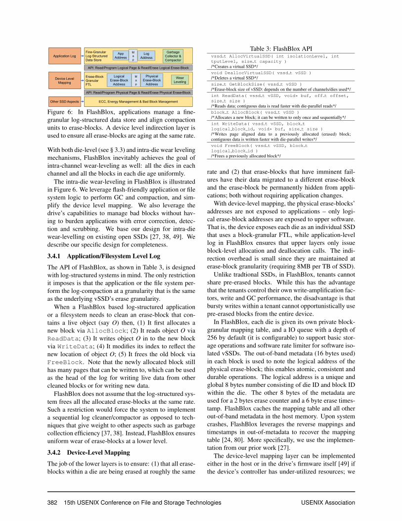
3.4 Intra Channel/Die Wear-LevelingThe goals of intra die wear-leveling are to ensure thatthe blocks in each die are aging at the same rate whileenabling applications to access data efficiently by avoid-ing the pitfalls of multiple indirection layers and redun-dant functionalities across these layers [27, 35, 54, 77].
USENIX Association 15th USENIX Conference on File and Storage Technologies 381
Application Log
Device Level
Mapping
Other SSD Aspects
Fine-Granular
Log-Structured
Data Store
M
a
p
App
AddressLog
Address
Garbage
Collector &
Compactor
Erase-Block
Granular
FTL
M
a
p
Logical
Erase-Block
Address
Physical
Erase-Block
Address
Wear
Leveling
ECC, Energy Management & Bad Block Management
API: Read/Program Logical Page & Read/Erase Logical Erase-Block
API: Read/Program Physical Page & Read/Erase Physical Erase-Block
Figure 6: In FlashBlox, applications manage a fine-granular log-structured data store and align compactionunits to erase-blocks. A device level indirection layer isused to ensure all erase-blocks are aging at the same rate.
With both die-level (see § 3.3) and intra-die wear levelingmechanisms, FlashBlox inevitably achieves the goal ofintra-channel wear-leveling as well: all the dies in eachchannel and all the blocks in each die age uniformly.
The intra-die wear-leveling in FlashBlox is illustratedin Figure 6. We leverage flash-friendly application or filesystem logic to perform GC and compaction, and sim-plify the device level mapping. We also leverage thedrive’s capabilities to manage bad blocks without hav-ing to burden applications with error correction, detec-tion and scrubbing. We base our design for intra-diewear-levelling on existing open SSDs [27, 38, 49]. Wedescribe our specific design for completeness.
3.4.1 Application/Filesystem Level Log
The API of FlashBlox, as shown in Table 3, is designedwith log-structured systems in mind. The only restrictionit imposes is that the application or the file system per-form the log-compaction at a granularity that is the sameas the underlying vSSD’s erase granularity.
When a FlashBlox based log-structured applicationor a filesystem needs to clean an erase-block that con-tains a live object (say O) then, (1) It first allocates anew block via AllocBlock; (2) It reads object O viaReadData; (3) It writes object O in to the new blockvia WriteData; (4) It modifies its index to reflect thenew location of object O; (5) It frees the old block viaFreeBlock. Note that the newly allocated block stillhas many pages that can be written to, which can be usedas the head of the log for writing live data from othercleaned blocks or for writing new data.
FlashBlox does not assume that the log-structured sys-tem frees all the allocated erase-blocks at the same rate.Such a restriction would force the system to implementa sequential log cleaner/compactor as opposed to tech-niques that give weight to other aspects such as garbagecollection efficiency [37, 38]. Instead, FlashBlox ensuresuniform wear of erase-blocks at a lower level.
3.4.2 Device-Level Mapping
The job of the lower layers is to ensure: (1) that all erase-blocks within a die are being erased at roughly the same
Table 3: FlashBlox APIvssd t AllocVirtualSSD( int isolationLevel, inttputLevel, size t capacity )/*Creates a virtual SSD*/void DeallocVirtualSSD( vssd t vSSD )/*Deletes a virtual SSD*/size t GetBlockSize( vssd t vSSD )/*Erase-block size of vSSD: depends on the number of channels/dies used*/int ReadData( vssd t vSSD, void* buf, off t offset,size t size )/*Reads data; contiguous data is read faster with die-parallel reads*/block t AllocBlock( vssd t vSSD )/*Allocates a new block; it can be written to only once and sequentially*/int WriteData( vssd t vSSD, block tlogical block id, void* buf, size t size )/*Writes page aligned data to a previously allocated (erased) block;contiguous data is written faster with die-parallel writes*/void FreeBlock( vssd t vSSD, block tlogical block id )/*Frees a previously allocated block*/
rate and (2) that erase-blocks that have imminent fail-ures have their data migrated to a different erase-blockand the erase-block be permanently hidden from appli-cations; both without requiring application changes.
With device-level mapping, the physical erase-blocks’addresses are not exposed to applications – only logi-cal erase-block addresses are exposed to upper software.That is, the device exposes each die as an individual SSDthat uses a block-granular FTL, while application-levellog in FlashBlox ensures that upper layers only issueblock-level allocation and deallocation calls. The indi-rection overhead is small since they are maintained aterase-block granularity (requiring 8MB per TB of SSD).
Unlike tradtional SSDs, in FlashBlox, tenants cannotshare pre-erased blocks. While this has the advantagethat the tenants control their own write-amplification fac-tors, write and GC performance, the disadvantage is thatbursty writes within a tenant cannot opportunistically usepre-erased blocks from the entire device.
In FlashBlox, each die is given its own private block-granular mapping table, and a IO queue with a depth of256 by default (it is configurable) to support basic stor-age operations and software rate limiter for software iso-lated vSSDs. The out-of-band metadata (16 bytes used)in each block is used to note the logical address of thephysical erase-block; this enables atomic, consistent anddurable operations. The logical address is a unique andglobal 8 bytes number consisting of die ID and block IDwithin the die. The other 8 bytes of the metadata areused for a 2 bytes erase counter and a 6 byte erase times-tamp. FlashBlox caches the mapping table and all otherout-of-band metadata in the host memory. Upon systemcrashes, FlashBlox leverages the reverse mappings andtimestamps in out-of-metadata to recover the mappingtable [24, 80]. More specifically, we use the implemen-tation from our prior work [27].
The device-level mapping layer can be implementedeither in the host or in the drive’s firmware itself [49] ifthe device’s controller has under-utilized resources; we
382 15th USENIX Conference on File and Storage Technologies USENIX Association

implement it in the host. Error detection, correction andmasking, and other low-level flash management systemsremain unmodified in FlashBlox.
Both the application/filesystem level log and thedevice-level mapping need to over provision, but fordifferent reasons. The log needs to over-provision forthe sake of garbage collection efficiency. Here, werely on the existing logic within log-structured, flash-aware applications and file systems to perform their ownover-provisioning appropriate for their workloads. Thedevice-level mapping needs its own over-provisioningfor the sake of retiring error-prone erase-blocks. In ourimplementation, we set this to 1% based on the error rateanalysis from our prior work [29].
3.5 Implementation DetailsPrototype SSD. We implement FlashBlox using aCNEX SSD [18] which is an open-channel SSD [44]containing 1 TB Toshiba A19 flash memory and an opencontroller that allows physical resource access from thehost. It has 16 channels, each channel has 4 dies, eachdie has 4 planes, each plane has 1024 blocks, each blockhas 256 pages with 16 KB page size. This hardware pro-vides basic I/O control commands to issue read, writeand erase operations against flash memory. We use amodified version of the CNEX firmware/driver stack thatallows us to independently queue requests to each die.FlashBlox is implemented using the C programming lan-guage in 11,219 lines of code (LoC) layered on top of theCNEX stack.
Prototype Application and Filesystem. We wereable to modify LevelDB key-value store and the Shore-MT database engine to use FlashBlox using only 38 and22 LoC modifications respectively. These modificationsare needed to use the APIs in Table 3. Additionally,we implemented a user-space log-structured file system(vLFS) with 1,809 LoC (only 26 LoC are from Flash-Blox API) based on FUSE for applications which cannotbe modified.
Resource Allocation. For each call to create a vSSD,the resource manager performs a linear search of all theavailable channels, dies and soft-planes to satisfy the re-quirements. A set of free lists of them are maintained forthis purpose. During deallocation, the resource managertakes the freed channels, dies and soft-planes and coa-lesces them when possible. For instance, if all the fourdies of a channel become free then the resource managercoalesces the dies into a channel and adds the channel tothe free channel set. In the future, we wish to explore ad-mission control and other resource allocation strategies.
4 EvaluationOur evaluation demonstrates that: (1) FlashBlox hasoverheads (WAF and CPU) comparable to state-of-the-
Table 4: Application workloads used for evaluation.Workload I/O Pattern
Key
-Val
ueSt
ore YCSB-A 50% read, 50% update
YCSB-B 95% read, 5% updateYCSB-C 100% readYCSB-D 95% read, 5% insertYCSB-E 95% scan, 5% insertYCSB-F 50% read, 50% read-modify-write
Dat
aC
ente
r Cloud Storage 26.2% read, 73.8% writeWeb Search 83.0% read, 17.0% write
Web PageRank 17.7% read, 82.2% writeMapReduce 52.9% read, 47.1% write
Dat
abas
es TPC-C mix (65.5% read, 34.5% write)TATP mix (81.2% read, 18.8% write)
TPC-B account update (100% write)TPC-E mix (90.7% read, 9.3% write)
art FTLs (§ 4.1); (2) Different levels of hardware isola-tion can be achieved by utilizing flash parallelism, andthey perform better than software isolation (§ 4.2.1);(3) Hardware isolation enables latency-sensitive appli-cations such as web search to effectively share an SSDwith bandwidth-intensive workloads like MapReducejobs (§ 4.2.2); (4) The impact of wear-leveling migra-tions on data center applications’ performance is low(§ 4.3.1) and (5) FlashBlox’s wear-leveling is near toideal (§ 4.3.2).
Experimental Setup: We used FIO benchmarks [20]and 14 different workloads for the evaluation (Table 4):six NoSQL workloads from the Yahoo Cloud Serv-ing Benchmarks (YCSB) [19], four database workloads:TPC-C [70], TATP [65], TPC-B [69] and TPC-E [71],and four storage workload traces collected from Mi-crosoft’s data centers.
YCSB is a framework for evaluating the performanceof NoSQL stores. All of the six core workloads con-sisting of A, B, C, D, E and F are used for the evalua-tion. LevelDB [39] is modified to run using the vSSDsfrom FlashBlox with various isolation levels. The open-source SQL database Shore-MT [55] is modified to workover the vSSDs of FlashBlox. The table size of the fourdatabase workloads TPC-C, TATP, TPC-B and TPC-Erange from 9 - 25 GB each. A wear-imbalance factorlimit of 1.1 is used for all our experiments to capture re-alistic swapping frequencies. The number of dies, chan-nels and planes used for each experiment is specified sep-arately for each experiment.
Storage intensive and latency sensitive applicationsfrom Microsoft’s data centers are instrumented to col-lect traces for cloud storage, web search, PageRank andMapReduce workloads. These applications are the first-party customers of Microsoft’s storage IaaS system.
4.1 MicrobenchmarksWe benchmark two vSSDs that each run an FIO bench-mark to evaluate FlashBlox’s WAF. Compared to the un-modified CNEX SSD’s page-level FTL, FlashBlox deliv-
USENIX Association 15th USENIX Conference on File and Storage Technologies 383

RW+SW RW+RW RW+SR RW+RR SW+SW SW+SR SW+RR0
0.250.500.751.001.251.501.752.00
WAF
FlashBloxUnmodified SSD
Figure 7: WAF comparison between FlashBlox and a tra-ditional SSD. RW/RR: random write/read; SW/SR: se-quential write/read.
ers lower WAFs as shown in Figure 7 because of the factthat FlashBlox’s vSSDs never share the same physicalflash blocks for storing their pages. As shown by previ-ous work [34], this reduces WAF because of absence offalse sharing of blocks at the application level. The dif-ferent types of vSSDs of FlashBlox have similar WAFsbecause they all use separate blocks, yet they provide dif-ferent throughput and tail latency levels (shown in Sec-tion 4.2) because of higher levels of isolation.
In addition, FlashBlox has up to 6% higher total sys-tem CPU usage compared to the unmodified CNEXSSD when running FIO. Despite merging the file sys-tem’s index with that of the FTL’s by using FlashBlox’sAPIs which reduces latency as shown by existing open-channel work [38, 49], the additional CPU overhead isdue to the device-level mapping layer that is accesed inevery critical path. As a future optimization for the pro-duction SSD, we plan to transparently move the device-level mapping layer into the SSD.
4.2 Isolation Level vs. Tail LatencyIn this section, we demonstrate that higher levels of iso-lation provide lower tail latencies. Multiple instances ofapplication workloads are run on individual vSSDs ofdifferent kinds. In each workload, the number of clientthreads executing transactions is gradually increased un-til the throughput tapers off. The maximum through-put achieved for the lowest number of threads is thenrecorded. The average and tail latencies of transactionsare recorded for the same number of threads.
4.2.1 Hardware Isolation vs. Software Isolation
In this experiment, the channel and die isolated vSSDsare evaluated against the software isolated vSSDs (withweighted fair sharing of storage bandwidth enabled). Webegin with a scenario of two LevelDB instances. Theyrun on two vSSDs in three different configurations, eachusing a different isolation level: high, medium, and low;they contain one channel, four dies and sixteen soft-planes respectively to ensure that the resources are con-sistent across experiments. The two instances run aYCSB workload each. The choice of YCSB is made forthis experiment to show how removing IO interferencecan improve the throughput and reduce latency for IO-bottlenecked applications.
A+A A+B A+C A+D A+E A+F0
20406080
100120140160
Thro
ughp
ut (K
ops
/sec
) DB1-in-Channel-Isolated-vSSDDB1-in-Die-Isolated-vSSDDB1-in-Software-Isolated-vSSD
DB2-in-Channel-Isolated-vSSDDB2-in-Die-Isolated-vSSDDB2-in-Software-Isolated-vSSD
Figure 8: The throughput of LevelDB+YCSB workloadsrunning at various levels of storage isolation.
Unisolated-vSSD
Software-Isolated-vSSD
Channel-Isolated-vSSD0.25
0.51248
163264
99th
Per
cent
ile
Late
ncy
(mill
isec
s) WebSearchMapReduce
(a) 99th Percentile Latency
Unisolated-vSSD
Software-Isolated-vSSD
Channel-Isolated-vSSD0
306090
120150180210
Ban
dwid
th (M
B/s
ec)
(b) BandwidthFigure 11: The performance of colocated Web Searchand MapReduce workload traces.
Each LevelDB instance is first populated with 32 GBof data and each key-value pair is 1 KB. The YCSB clientthreads perform 50 million CRUD (i.e., create, read, up-date and delete) operations against each LevelDB in-stance. We pick the size of the database and number ofoperations such that GC is always triggered. YCSB C isread-only, thus we report results for read operations only.
The total number of dies in each setting is the same. Inthe channel isolation case, two vSSDs are allocated fromtwo different channels. In the die isolation case, bothvSSDs share the channels, but are isolated at the die levelwithin the channel. In the software isolation case, bothvSSDs are striped across all the dies in two channels.
Figure 8 shows that on average, channel isolated vSSDprovides 1.3x better throughput compared to die isolatedvSSD and 1.6x compared to the software isolated vSSD.Similarly, higher levels of isolation lead to lower averagelatencies as shown in Figure 9 (a) and Figure 9 (b). Thisis because higher levels of isolation suffer from less in-terference between read and write operations from otherinstances. Die isolated vSSDs have to share the bus witheach other, thus, their performance is worse than chan-nel isolated vSSDs, which are fully isolated in hardware.Software isolated vSSDs share the same dies with eachother, suffering from higher interference.
Tail latency improvements are much more significant.As shown in Figure 9 (c) and Figure 9 (d), channel iso-lated vSSDs provide up to 1.7x lower tail latency com-pared to die isolated vSSDs and up to 2.6x lower tail la-tency compared to vSSDs that stripe data across all thedies akin to software isolated vSSDs whose operationsare not fully isolated from each other.
A similar experiment with four LevelDB instances isalso performed. Tail latency results are shown in Fig-ure 10 where channel isolated vSSDs provide up to 3.1xlower tail latency compared the software isolated vSSDs.
384 15th USENIX Conference on File and Storage Technologies USENIX Association

A+A A+B A+C A+D A+E A+F(a) Read (Average)
050
100150200250300350400
Mic
rose
cond
sDB1-in-Channel-Isolated-vSSD DB1-in-Die-Isolated-vSSD DB1-in-Software-Isolated-vSSD DB2-in-Channel-Isolated-vSSD DB2-in-Die-Isolated-vSSD DB2-in-Software-Isolated-vSSD
A+A A+B A+C A+D A+E A+F(b) Update (Average)
A+A A+B A+C A+D A+E A+F(c) Read (99th Percentile)
0200400600800
100012001400
A+A A+B A+C A+D A+E A+F(d) Update (99th Percentile)
Figure 9: The average and 99th percentile latencies of LevelDB+YCSB workloads running at various levels of storageisolation. Compared to die and software isolated vSSDs, channel isolated vSSD reduces the average latency by 1.2xand 1.4x respectively, and decreases the 99th percentile latency by 1.2 - 1.7x and 1.9 - 2.6x respectively. Note that theupdate latencies are not applicable for workload C which is read-only.
A+A+A+AA+B+A+B
A+C+A+CA+D+A+D
A+E+A+EA+F+A+F
A+B+C+DC+D+E+F
0200400600800
1000120014001600
Late
ncy
(mic
rose
cond
s) DB1-in-Channel-Isolated-vSSDDB2-in-Channel-Isolated-vSSDDB3-in-Channel-Isolated-vSSDDB4-in-Channel-Isolated-vSSD
DB1-in-Software-Isolated-vSSDDB2-in-Software-Isolated-vSSDDB3-in-Software-Isolated-vSSDDB4-in-Software-Isolated-vSSD
(a) Read Latency (99th Percentile)
A+A+A+AA+B+A+B
A+C+A+CA+D+A+D
A+E+A+EA+F+A+F
A+B+C+DC+D+E+F
(b) Update Latency (99th Percentile)
Figure 10: The 99th percentile latency of running four LevelDB instances with various levels of storage isolation. Thechannel isolated vSSD reduces the 99th percentile latency by 1.3 - 2.7x and 1.5 - 3.1x for read and update operationrespectively, compared to software isolated vSSD.
4.2.2 Latency vs. Bandwidth Sensitive Tenants
We now evaluate how hardware isolation provides bene-fits for instances that share the same physical SSD whenone is latency sensitive while others are not (for resourceefficiency [42]). Channel, software isolated and uniso-lated vSSDs are used in this experiment. The total num-ber of dies is the same in all three settings and is eight.The workloads from a large cloud provider are used forperforming this experiment. Web search is the instancethat requires lower tail latencies while MapReduce jobsare not particularly latency sensitive.
Results shown in Figure 11 demonstrate three trends:First, channel isolated vSSDs provide the best compro-mise between throughput and tail latency: tail latencyof the web search workloads decreases by over 2x for a36% reduction of bandwidth of the MapReduce job whencompared to an unisolated vSSD. The fall in throughputof MapReduce is expected because it only has half of thechannels of the unisolated case where its large sequentialIOs end up consuming the bandwidth unfairly due to thelack of any isolation techniques.
Second, software isolated vSSDs for web search andMapReduce can reduce the tail latency of web search tothe same level as the channel-isolated case, but the band-width of the MapReduce job decreases by more than 4xwhen compared to the unisolated vSSD. This is also ex-pected because the work that an SSD can perform is aconvex combination of IOPS and bandwidth. Web searchtakes a significant number of small IOPS when sharingbandwidth fairly with MapReduce and this in-turn re-duces the total bandwidth available for MapReduce.
4.3 Wear-Leveling Efficacy and OverheadWear-leveling in FlashBlox is supported in two differentlayers. One layer ensures that all the dies in the systemare aging at the same rate overall with channel migra-tions, while the other layer ensures that blocks within agiven die are aging at the same rate overall. Its overheadand efficacy are evaluated in this section.
4.3.1 Migration Overhead
We first evaluate the overhead of the migration mecha-nism. We migrate one channel and measure the changein throughput and 99th percentile latency on a variety ofYCSB workloads that are running on the channel.
The throughput of LevelDB running on that channeldrops by no more than 33.8% while the tail latencies ofreads and updates increase by up to 22.1% (Figure 12).For simplicity, we show results for migrating 1 GB ofthe 64GB channel. We use a single thread and the datamoves at a rate of 78.9MBPS. Moving all of the 64 GBof data would take close to 15 minutes.
The impact of migration on web search and MapRe-duce workloads is shown in Figure 13. During migra-tion, the bandwidth of the MapReduce job decreases by36.7%, the tail latencies of reads and writes of the websearch increase by 34.2%. These performance slow-downs bring channel-isolation numbers on par with thesoftware isolation. This implies that a 36.7% drop for15 minutes when amortized over our recommended swaprate represents a 0.04% overall drop.
4.3.2 Migration Frequency Analysis
To evaluate the wear-leveling efficacy, we built a simula-tor and used it to understand how the device ages for var-
USENIX Association 15th USENIX Conference on File and Storage Technologies 385

A B C D E F0
306090
120
Thro
ughp
ut
(K o
ps/s
ec) Without Migration With Migration
(a) Throughput
A B C D E F0
100200300400
Mic
rose
cond
s
(b) Read (99th Percentile)
A B C D E F0
100200300400500600
Mic
rose
cond
s
(c) Update (99th Percentile)
Figure 12: The impact of a channel migration on workloads: LevelDB’s throughput falls by 33.8%, its 99th percentileread and update latencies increase by 22.1% and 18.7% respectively.
0 5 10 15 20 25 30 35 40 45 50 55Time (seconds)
0
50
100
Ban
dwid
th
(MB
/sec
) Read Write
(a) Bandwidth of MapReduce
0 5 10 15 20 25 30 35 40 45 50 55Time (seconds)
0.300.350.400.450.50
Late
ncy
(mill
isec
onds
)
Read
(b) Read Latency of Web Search
0 5 10 15 20 25 30 35 40 45 50 55Time (seconds)
1.01.21.41.61.8
Late
ncy
(mill
isec
onds
)
Write
(c) Write Latency of Web Search
Figure 13: The overhead of migrating 1GB of data as MapReduce and web search are running on the channels involved:MapReduce’s bandwidth falls by up to 36.7% while web search’s latency increases by up to 34.2%.
1 2 4 8 12 16Number of Workloads
0123456
Year
s
NoSwapIdeal SSDswap per 1 weekswap per 2 weeksswap per 4 weeksswap per 8 weeksFlashBlox
(a) Channel Killer
1 2 4 8 12 16Number of Workloads
02468
1012
Year
s
(b) Die Killer
Figure 14: SSD lifetime of running adversarial writeworkloads that stress a single channel or a die.
ious workloads. For workload traces that are not from alog-structured application, we first execute the workloadon the log-structured file system vLFS built using Flash-Blox and trace FlashBlox API calls. We measure theblock consumption rate of these traces to evaluate the ef-ficacy of wear-leveling. For the CNEX SSD, γ = M/ f =24 TB (discussed in § 3.1.5). The supported number ofprogram erase (PE) cycles is 10 K in our drive. Our ab-solute lifetimes scale linearly for other SSDs and factorimprovements remain the same regardless of the numberof supported PE cycles.
Worst-case workloads. To evaluate the possibleworst cases for SSDs, we run the most write-intensiveworkloads against a few channels (channel killer) anddies (die killer). We gradually increase the number ofsuch workloads to stress the SSD. Each workload ispinned to exactly one channel or one die while keepingother channels or dies for read-only operations.
Figure 14 shows the SSD’s lifetime for a variety ofwear-leveling schemes. Without wear-leveling (NoSwapin Figure 14), the SSD dies after less than 4 months,while FlashBlox can always guarantee 95% of the ideallifetime within migration frequency of once per ≤ 4weeks for both channel and die killer workloads. Theadaptive wear-leveling scheme in FlashBlox automati-cally migrates a channel by adjusting to write-rates.
Mixed workloads. In real-world scenarios, a mix ofvarious kinds of workloads would run on the same SSD.We use all the 14 workloads (Table 4) simultaneously in
1 12 24 36 48 60 72 84 96 108 120 132 144 156
Time (weeks)
1.01.11.21.31.41.51.61.71.81.92.02.12.22.32.42.52.62.72.82.93.03.1
Wea
r Im
bala
nce
(Max
/Avg
) No Swapswap per 1 weekswap per 2 weeksswap per 4 weeksswap per 8 weeksFlashBlox
Figure 15: Wear imbalance of FlashBlox with differentwear-leveling schemes. The ideal wear imbalance is 1.0.
Table 5: Monte Carlo simulation (10K runs) of SSD life-time with randomly sampled workloads on the channels.
#vSSDNoSwap
Lifetime (Years)Ideal vs. FlashBlox
Lifetime (Years) Wear Im-balance
Swap Once inDays (Avg)99th 50th 99th 50th
4 1.2 1.6 6.2/6.1 13.8/13.5 1.02 948 1.2 1.3 3.7/3.6 6.7/6.6 1.02 2216 1.2 1.2 2.1/2.1 3.4/3.3 1.01 19
the experiment, and measure FlashBlox’s wear leveling.Fourteen channel isolated vSSDs are created for runningthese workloads and migrations. Figure 5 shows how theerase rates of these applications vary.
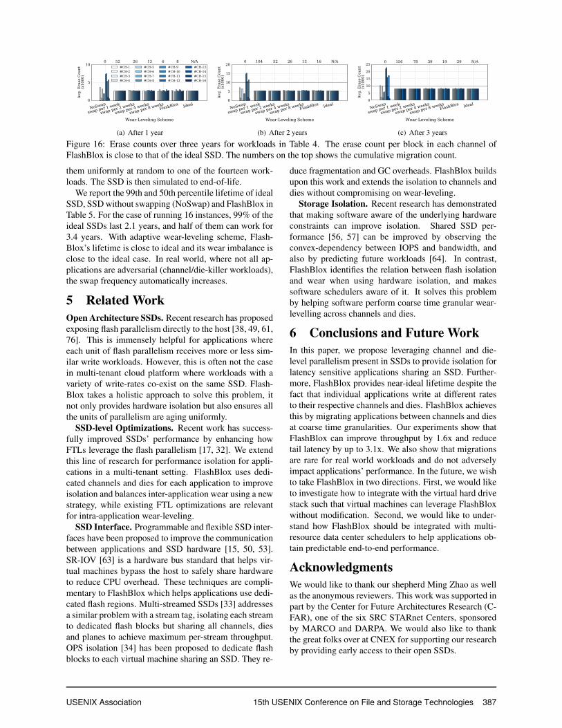
For the scheme without any migrations, the wear im-balance is 3.1, and the SSD dies after 1.2 years. Also,results show that blocks are more or less evenly aged fora migration frequency as high as once in four weeks, asshown in Figure 15. This indicates that for realistic sce-narios, where write traffic is more evenly matched, sig-nificantly fewer swaps could be tolerated.
Figure 16 shows the absolute erase counts of the chan-nels (including the erases needed for migrations andGC). Compared to the ideal wear-leveling, the absoluteerase counts are almost the same with the migration fre-quency of a week.
To further evaluate FlashBlox’s wear-leveling efficacy,we run a Monte Carlo simulation (10K runs) of the SSDlifetime. We create various number of vSSDs and assign
386 15th USENIX Conference on File and Storage Technologies USENIX Association
NoSwap
swap per 1 week
swap per 2 weeks
swap per 4 weeks
swap per 8 weeksFlashBlox Ideal
Wear-Leveling Scheme
0
5
10
Avg.
Era
se C
ount
(x10
00)
0 52 26 13 6 8 N/A#CH-1#CH-2#CH-3#CH-4
#CH-5#CH-6#CH-7#CH-8
#CH-9#CH-10#CH-11#CH-12
#CH-13#CH-14#CH-15#CH-16
(a) After 1 year
NoSwap
swap per 1 week
swap per 2 weeks
swap per 4 weeks
swap per 8 weeksFlashBlox Ideal
Wear-Leveling Scheme
0
5
10
15
20
Avg.
Era
se C
ount
(x10
00)
0 104 52 26 13 16 N/A
(b) After 2 years
NoSwap
swap per 1 week
swap per 2 weeks
swap per 4 weeks
swap per 8 weeksFlashBlox Ideal
Wear-Leveling Scheme
0
5
10
15
20
25
Avg.
Era
se C
ount
(x10
00)
0 156 78 39 19 29 N/A
(c) After 3 years
Figure 16: Erase counts over three years for workloads in Table 4. The erase count per block in each channel ofFlashBlox is close to that of the ideal SSD. The numbers on the top shows the cumulative migration count.
them uniformly at random to one of the fourteen work-loads. The SSD is then simulated to end-of-life.
We report the 99th and 50th percentile lifetime of idealSSD, SSD without swapping (NoSwap) and FlashBlox inTable 5. For the case of running 16 instances, 99% of theideal SSDs last 2.1 years, and half of them can work for3.4 years. With adaptive wear-leveling scheme, Flash-Blox’s lifetime is close to ideal and its wear imbalance isclose to the ideal case. In real world, where not all ap-plications are adversarial (channel/die-killer workloads),the swap frequency automatically increases.
5 Related WorkOpen Architecture SSDs. Recent research has proposedexposing flash parallelism directly to the host [38, 49, 61,76]. This is immensely helpful for applications whereeach unit of flash parallelism receives more or less sim-ilar write workloads. However, this is often not the casein multi-tenant cloud platform where workloads with avariety of write-rates co-exist on the same SSD. Flash-Blox takes a holistic approach to solve this problem, itnot only provides hardware isolation but also ensures allthe units of parallelism are aging uniformly.
SSD-level Optimizations. Recent work has success-fully improved SSDs’ performance by enhancing howFTLs leverage the flash parallelism [17, 32]. We extendthis line of research for performance isolation for appli-cations in a multi-tenant setting. FlashBlox uses dedi-cated channels and dies for each application to improveisolation and balances inter-application wear using a newstrategy, while existing FTL optimizations are relevantfor intra-application wear-leveling.
SSD Interface. Programmable and flexible SSD inter-faces have been proposed to improve the communicationbetween applications and SSD hardware [15, 50, 53].SR-IOV [63] is a hardware bus standard that helps vir-tual machines bypass the host to safely share hardwareto reduce CPU overhead. These techniques are compli-mentary to FlashBlox which helps applications use dedi-cated flash regions. Multi-streamed SSDs [33] addressesa similar problem with a stream tag, isolating each streamto dedicated flash blocks but sharing all channels, diesand planes to achieve maximum per-stream throughput.OPS isolation [34] has been proposed to dedicate flashblocks to each virtual machine sharing an SSD. They re-
duce fragmentation and GC overheads. FlashBlox buildsupon this work and extends the isolation to channels anddies without compromising on wear-leveling.
Storage Isolation. Recent research has demonstratedthat making software aware of the underlying hardwareconstraints can improve isolation. Shared SSD per-formance [56, 57] can be improved by observing theconvex-dependency between IOPS and bandwidth, andalso by predicting future workloads [64]. In contrast,FlashBlox identifies the relation between flash isolationand wear when using hardware isolation, and makessoftware schedulers aware of it. It solves this problemby helping software perform coarse time granular wear-levelling across channels and dies.
6 Conclusions and Future WorkIn this paper, we propose leveraging channel and die-level parallelism present in SSDs to provide isolation forlatency sensitive applications sharing an SSD. Further-more, FlashBlox provides near-ideal lifetime despite thefact that individual applications write at different ratesto their respective channels and dies. FlashBlox achievesthis by migrating applications between channels and diesat coarse time granularities. Our experiments show thatFlashBlox can improve throughput by 1.6x and reducetail latency by up to 3.1x. We also show that migrationsare rare for real world workloads and do not adverselyimpact applications’ performance. In the future, we wishto take FlashBlox in two directions. First, we would liketo investigate how to integrate with the virtual hard drivestack such that virtual machines can leverage FlashBloxwithout modification. Second, we would like to under-stand how FlashBlox should be integrated with multi-resource data center schedulers to help applications ob-tain predictable end-to-end performance.
AcknowledgmentsWe would like to thank our shepherd Ming Zhao as wellas the anonymous reviewers. This work was supported inpart by the Center for Future Architectures Research (C-FAR), one of the six SRC STARnet Centers, sponsoredby MARCO and DARPA. We would also like to thankthe great folks over at CNEX for supporting our researchby providing early access to their open SSDs.
USENIX Association 15th USENIX Conference on File and Storage Technologies 387

References[1] N. Agarwal, V. Prabhakaran, T. Wobber, J. D. Davis,
M. Manasse, and R. Panigrahy. Design Tradeoffs for SSDPerformance. In Proc. USENIX ATC, Boston, MA, June2008.
[2] Amazon Relational Database Service.https://aws.amazon.com/rds/.
[3] Amazon Relational Database Service Pricing.https://aws.amazon.com/rds/pricing/.
[4] Amazon’s SSD Backed EBS.https://aws.amazon.com/blogs/aws/new-ssd-backed-elastic-block-storage/.
[5] Azure DocumentDB.https://azure.microsoft.com/en-us/services/documentdb/.
[6] Azure DocumentDB Pricing.https://azure.microsoft.com/en-us/pricing/details/documentdb/.
[7] Azure Premium Storage.https://azure.microsoft.com/en-us/documentation/articles/storage-premium-storage/.
[8] Azure Service Fabric.https://azure.microsoft.com/en-us/services/service-fabric/.
[9] Azure SQL Database.https://azure.microsoft.com/en-us/services/sql-database/.
[10] Azure SQL Database Pricing.https://azure.microsoft.com/en-us/pricing/details/sql-database/.
[11] S. Blagodurov, S. Zhuravlev, M. Dashti, and A. Fedorova.A Case for NUMA-aware Contention Management onMulticore Systems. In Proc. USENIX ATC’11, Berkeley,CA, June 2011.
[12] Block IO Bandwidth (Blkio) in Docker.https://docs.docker.com/engine/reference/run/#block-io-bandwidth-blkio-constraint.
[13] Block IO Controller.https://www.kernel.org/doc/Documentation/cgroup-v1/blkio-controller.txt.
[14] Y. Bu, H. Lee, and J. Madhavan. Comparing SSD-placement Strategies to scale a Database-in-the-Cloud. InProc. SoCC’13, Santa Clara, CA, Oct. 2013.
[15] A. M. Caulfield, T. I. Mollov, L. Eisner, A. De, J. Coburn,and S. Swanson. Providing safe, user space access to fast,solid state disks. In Proc. ACM ASPLOS’12, London,United Kingdom, Mar. 2012.
[16] CGROUPS.https://www.kernel.org/doc/Documentation/cgroup-v1/cgroups.txt.
[17] F. Chen, R. Lee, and X. Zhang. Essential Roles of Ex-ploiting Internal Parallelism of Flash Memory based SolidState Drives in High-Speed Data Processing. In Proc.HPCA’11, San Antonio, Texas, Feb. 2011.
[18] CNEX Labs.http://www.cnexlabs.com/index.php.
[19] B. F. Cooper, A. Silberstein, E. Tam, R. Ramakrishnan,and R. Sears. Benchmarking cloud serving systems withycsb. In Proc. SoCC’12, Indianapolis, Indiana, June2010.
[20] FIO Benchmarks.https://linux.die.net/man/1/fio.
[21] Fusion-io ioDrive.https://www.sandisk.com/business/datacenter/products/flash-devices/pcie-flash/sx350.
[22] Google Cloud Platform: Local SSDs.https://cloud.google.com/compute/docs/disks/local-ssd.
[23] Google Cloud SQL.https://cloud.google.com/sql/.
[24] A. Gupta, Y. Kim, and B. Urgaonkar. DFTL: A FlashTranslation Layer Employing Demand-based SelectiveCaching of Page-level Address Mappings. In Proc. ACMASPLOS, Washington, DC, Mar. 2009.
[25] M. Hao, G. Soundararajan, D. Kenchammana-Hosekote,A. A. Chien, and H. S. Gunawi. The Tail at Store: A Rev-elation from Millions of Hours of Disk and SSD Deploy-ments. In Proc. FAST’16, Santa Clara, CA, Feb. 2016.
[26] J. He, D. Nguyen, A. C. Arpaci-Dusseau, and R. H.Arpaci-Dusseau. Reducing File System Tail Latencieswith Chopper. In Proc. FAST’15, Santa Clara, CA, Feb.2015.
[27] J. Huang, A. Badam, M. K. Qureshi, and K. Schwan. Uni-fied Address Translation for Memory-Mapped SSD withFlashMap. In Proc. ISCA’15, Portland, OR, June 2015.
[28] Intel Inc. Improving Real-Time Performance by UtilizingCache Allocation Technology. White Paper, 2015.
[29] Iyswarya Narayanan and Di Wang and Myeongjae Jeonand Bikash Sharma and Laura Caulfield and Anand Siva-subramaniam and Ben Cutler and Jie Liu and BadriddineKhessib and Kushagra Vaid. SSD Failures in Datacenters:What? When? and Why? In Proc. ACM SYSTOR’16,Haifa, Israel, June 2016.
[30] V. Jeyakumar, M. Alizadeh, D. Mazieres, B. Prabhakar,C. Kim, and A. Greenberg. EyeQ: Practical Network Per-formance Isolation at the Edge. In Proc. NSDI’13, Berke-ley, CA, Apr. 2013.
[31] W. K. Josephson, L. A. Bongo, K. Li, and D. Flynn. DFS:A File System for Virtualized Flash Storage. ACM Trans.on Storage, 6(3):14:1–14:25, 2010.
[32] M. Jung and M. K. Ellis H. Wilson III. Physically Ad-dressed Queueing (PAQ): Improving Parallelism in SolidState Disks. In Proc. ISCA’12, Portland, OR, June 2012.
388 15th USENIX Conference on File and Storage Technologies USENIX Association

[33] J.-U. Kang, J. Hyun, H. Maeng, and S. Cho. The Multi-Streamed Solid-State Drive. In Proc. HotStorage’14,Philadelphia, PA, June 2014.
[34] J. Kim, D. Lee, and S. H. Noh. Towards SLO ComplyingSSDs Through OPS Isolation. In Proc. FAST’15, SantaClara, CA, Feb. 2015.
[35] W.-H. Kim, B. Nam, D. Park, and Y. Won. ResolvingJournaling of Journal Anomaly in Android IO: Multi-version B-tree with Lazy Split. In FAST’14, Santa Clara,CA, Feb. 2014.
[36] R. Konishi, Y. Amagai, K. Sato, H. Hifumi, S. Kihara, andS. Moriai. The Linux implementation of a log-structuredfile system. SIGOPS OSR, 40(3), 2006.
[37] C. Lee, D. Sim, J.-Y. Hwang, and S. Cho. F2FS: A NewFile System for Flash Storage. In Proc. FAST’15, SantaClara, CA, Feb. 2015.
[38] S. Lee, M. Liu, S. Jun, S. Xu, J. Kim, and Arvind.Application-Managed Flash. In Proc. FAST’16, SantaClara, CA, Feb. 2016.
[39] LevelDB.https://github.com/google/leveldb.
[40] J. Leverich and C. Kozyrakis. Reconciling High ServerUtilization and Sub-millisecond Quality-of-Service. InProc. EuroSys’14, Amsterdam, Netherlands, Apr. 2014.
[41] N. Li, H. Jiang, D. Feng, and Z. Shi. PSLO: Enforcing theXth Percentile Latency and Throughput SLOs for Consol-idated VM Storage. In Proc. EuroSys’16, London, UnitedKingdom, Apr. 2016.
[42] D. Lo, L. Cheng, R. Govindaraju, P. Ranganathan, andC. Kozyrakis. Heracles: Improving Resource Efficiencyat Scale. In Proc. ISCA’15, Portland, OR, June 2015.
[43] J. Mars, L. Tang, R. Hundt, K. Skadron, and M. L. Soffa.Bubble-Up: Increasing Utilization in Modern WarehouseScale Computers via Sensible Co-locations. In Proc. MI-CRO’11, Porto Alegre, Brazil, Dec. 2011.
[44] Matias Bjorling and Javier Gonzalez and Philippe Bon-net. LightNVM: The Linux Open-Channel SSD Subsys-tem. In Proc. USENIX FAST’17, Santa Clara, CA, Feb.2016.
[45] H. Menon and L. Kale. A Distributed Dynamic Load Bal-ancer for Iterative Applications. In Proc. SC’13, Denver,Colorado, Nov. 2013.
[46] Microsoft’s Open Source Cloud Hardware.https://azure.microsoft.com/en-us/blog/microsoft-reimagines-open-source-cloud-hardware/.
[47] S. P. Muralidhara, L. Subramanian, O. Mutlu, M. Kan-demir, and T. Moscibroda. Reducing Memory Interfer-ence in Multicore Systems via Application-Aware Mem-ory Channel Partitioning. In Proc. MICRO’11, Porto Ale-gre, Brazil, Dec. 2011.
[48] R. Nathuji, A. Kansal, and A. Ghaffarkhah. Q-Clouds:Managing Performance Interference Effects for QoS-Aware Clouds. In Proc. EuroSys’12, Paris, France, Apr.2010.
[49] J. Ouyang, S. Lin, S. Jiang, Y. Wang, W. Qi, J. Cong, andY. Wang. SDF: Software-Defined Flash for Web-ScaleInternet Storage Systems. In Proc. ACM ASPLOS, SaltLake City, UT, Mar. 2014.
[50] X. Ouyang, D. Nellans, R. Wipfel, D. Flynn, and D. K.Panda. Beyond Block I/O: Rethinking Traditional StoragePrimitives. In Proc. HPCA’11, San Antonio, Texas, Feb.2014.
[51] M. Rosenblum and J. K. Ousterhout. The Design andImplementation of a Log-Structured File System. ACMTrans. on Computer Systems, 10(1):26–52, Feb. 1992.
[52] D. Sanchez and C. Kozyrakis. Vantage: Scalable and Ef-ficient Fine-Grain Cache Partitioning. In Proc. ISCA’11,San Jose, CA, June 2011.
[53] S. Seshadri, M. Gahagan, S. Bhaskaran, T. Bunker, A. De,Y. Jin, Y. Liu, and S. Swanson. Willow: A User-Programmable SSD. In Proc. OSDI’14, Broomfield, CO,Oct. 2014.
[54] K. Shen, S. Park, and M. Zhu. Journaling of journal is(almost) free. In Proc. FAST’14, Berkeley, CA, 2014.
[55] Shore-MT.https://sites.google.com/site/shoremt/.
[56] D. Shue and M. J. Freedman. From Application Requeststo Virtual IOPs: Provisioned Key-Value Storage with Li-bra. In Proc. EuroSys’14, Amsterdam, Netherlands, Apr.2014.
[57] D. Shue, M. J. Freedman, and A. Shaikh. PerformanceIsolation and Fairness for Multi-Tenant Cloud Storage. InProc. OSDI’12, Hollywood, CA, Oct. 2012.
[58] D. Shukla, S. Thota, K. Raman, M. Gajendran, A. Shah,S. Ziuzin, K. Sundama, M. G. Guajardo, A. Wawrzy-niak, S. Boshra, R. Ferreira, M. Nassar, M. Koltachev,J. Huang, S. Sengupta, J. Levandoski, and D. Lomet.Schema-agnostic indexing with azure documentdb. InProc. VLDB’15, Kohala Coast, Hawaii, Sept. 2015.
[59] A. Singh, M. Korupolu, and D. Mohapatra. Server-Storage Virtualization: Integration and Load Balancing inData Centers. In Proc. SC’08, Austin, Texas, Nov. 2008.
[60] D. Skourtis, D. Achlioptas, N. Watkins, C. Maltzahn, andS. Brandt. Flash on rails: consistent flash performancethrough redundancy. In Proc. USENIX ATC’14, Philadel-phia, PA, June 2014.
[61] X. Song, J. Yang, and H. Chen. Architecting Flash-based Solid-State Drive for High-performance I/O Virtu-alization. IEEE Computer Architecture Letters, 13:61–64,2014.
[62] SQL Database Options and Performance: UnderstandWhat’s Available in Each Service Tier.https://azure.microsoft.com/en-us/documentation/articles/sql-database-service-tiers/#understanding-dtus.
USENIX Association 15th USENIX Conference on File and Storage Technologies 389
[63] SR-IOV for SSDs.http://www.snia.org/sites/default/files/Accelerating%20Storage%20Perf%20in%20Virt%20Servers.pdf.
[64] Sungyong Ahn and Kwanghyun La and Jihong Kim.Improving I/O Resource Sharing of Linux Cgroup forNVMe SSDs on Multi-core Systems. In Proc. USENIXHotStorage’16, Denver, CO, June 2016.
[65] TATP Benchmark.http://tatpbenchmark.sourceforge.net/.
[66] E. Thereska, H. Ballani, G. O’Shea, T. Karagiannis,A. Rowstron, T. Talpey, R. Black, and T. Zhu. IOFlow:A Software-Defined Storage Architecture. In Proc.SOSP’13, Farmington, PA, Nov. 2013.
[67] Throtting IO with Linux.https://fritshoogland.wordpress.com/2012/12/15/throttling-io-with-linux.
[68] Token Bucket Algorithm.https://en.wikipedia.org/wiki/token_bucket.
[69] TPCB Benchmark.http://www.tpc.org/tpcb/.
[70] TPCC Benchmark.http://www.tpc.org/tpcc/.
[71] TPCE Benchmark.http://www.tpc.org/tpce/.
[72] Traffic Control HOWTO.http://linux-ip.net/articles/Traffic-Control-HOWTO/.
[73] B. Trushkowsky, P. Bodik, A. Fox, M. J. Franklin, M. I.Jordan, and D. A. Patterson. The SCADS Director: Scal-
ing a Distributed Storage System Under Stringent Perfor-mance Requirements. In Proc. FAST’11, Santa Clara, CA,Feb. 2016.
[74] H. Wang and P. Varman. Balancing Fairness and Effi-ciency in Tiered Storage Systems with Bottleneck-AwareAllocation. In Proc. FAST’14, Santa Clara, CA, Feb.2014.
[75] J. Wang and Y. Hu. WOLF: A Novel reordering writebuffer to boost the performance of log-structured file sys-tems. In Proc. FAST’02, Monterey, CA, Jan. 2002.
[76] P. Wang, G. Sun, S. Jiang, J. Ouyang, S. Lin, C. Zhang,and J. Cong. An Effective Design and Implementationof LSM-Tree based Key-Value Store on Open-ChannelSSD. In Proc. EuroSys’14, Amsterdam, the Netherlands,Apr. 2014.
[77] J. Yang, N. Plasson, G. Gillis, N. Talagala, and S. Sun-dararaman. Don’t stack your Log on my Log. In Proc.INFLOW’14, Broomfield, CO, Oct. 2014.
[78] S. Yang, T. Harter, N. Agrawal, S. S. Kowsalya, A. Krish-namurthy, S. AI-Kiswany, R. T. Kaushik, A. C. Arpaci-Dusseau, and R. H. Arpaci-Dusseau. Split-Level I/OScheduling. In Proc. SOSP’15, Monterey, CA, Oct. 2015.
[79] N. Zhang, J. Tatemura, J. M. Patel, and H. Hacigu-mus. Re-evaluating Designs for Multi-Tenant OLTPWorkloads on SSD-based I/O Subsystems. In Proc. SIG-MOD’14, Snowbird, UT, June 2014.
[80] Y. Zhang, L. P. Arulraj, A. C. Arpaci-Dusseau, and R. H.Arpaci-Dusseau. De-indirection for Flash-based SSDswith Nameless Writes. In Proc. 10th USENIX FAST, SanJose, CA, Feb. 2012.
390 15th USENIX Conference on File and Storage Technologies USENIX Association