flanges 150 lb - capex cancapexcan.com/ftp/flangefl1-21.pdf · flanges 150 lb fl-1. flanges 300 lb...
TRANSCRIPT

FLANGES 150 LBASA B16.5
COMMON DIMENSIONS BORE LENGTH THRU HUBNOMINAL THICK- O.D. DIAM. WELD- WELD- SLIP-ON DIAM. RADIUS THREAD
PIPE OUTSIDE NESS RAISED AT BASE ING SLIP- LAP ING AND LAP HUB AT OF LENGTHDRILLING BOLTING APPROX. WEIGHT EACH - POUNDS SIZE DIAM. MIN. FACE OF HUB NECK ON JOINT NECK THR'D JOINT BEVEL FILLET MIN.
NOMINAL BOLT NUM. DIAM. DIAM. MACHINE STUD BOLT LENGTH NOMINAL WELD- SLIP-ON O C R X B1 B2 B3 Y1 Y2 Y3 A r T PIPE CIRCLE OF OF OF BOLT LENGTH RAISED RING PIPE ING AND LAP 1/2 3 1/2 7/16 1 3/8 1 3/16 .62 .88 .90 1 7/8 5/8 5/8 .84 1/8 5/8SIZE DIAM. HOLES HOLES BOLTS RAISED FACE FACE JOINT SIZE NECK THR'D JOINT BLIND 3/4 3 7/8 1/2 1 11/16 1 1/2 .82 1.09 1.11 2 1/16 5/8 5/8 1.05 1/8 5/81/2 2 3/8 4 5/8 1/2 1 3/4 2 1/4 - - 1/2 2 1 1 1 1 4 1/4 9/16 2 1 15/16 1.05 1.36 1.38 2 3/16 11/16 11/16 1.32 1/8 11/163/4 2 3/4 4 5/8 1/2 2 2 1/4 - - 3/4 2 2 2 2 1 1/4 4 5/8 5/8 2 1/2 2 5/16 1.38 1.70 1.72 2 1/4 13/16 13/16 1.66 3/16 13/161 3 1/8 4 5/8 1/2 2 2 1/2 3 1 3 2 2 2 1 1/2 5 11/16 2 7/8 2 9/16 1.61 1.95 1.97 2 7/16 7/8 7/8 1.90 1/4 7/8
1 1/4 3 1/2 4 5/8 1/2 2 1/4 2 1/2 3 1 1/4 3 3 3 3 2 6 3/4 3 5/8 3 1/16 2.07 2.44 2.46 2 1/2 1 1 2.38 5/16 11 1/2 3 7/8 4 5/8 1/2 2 1/4 2 3/4 3 1/4 1 1/2 4 3 3 4 2 1/2 7 7/8 4 1/8 3 9/16 2.47 2.94 2.97 2 3/4 1 1/8 1 1/8 2.88 5/16 1 1/8
2 4 3/4 4 3/4 5/8 2 3/4 3 3 1/2 2 6 5 5 5 3 7 1/2 15/16 5 4 1/4 3.07 3.57 3.60 2 3/4 1 3/16 1 3/16 3.50 3/8 1 3/162 1/2 5 1/2 4 3/4 5/8 3 3 1/4 3 3/4 2 1/2 8 7 7 7 3 1/2 8 1/2 15/16 5 1/2 4 13/16 3.55 4.07 4.10 2 13/16 1 1/4 1 1/4 4.00 3/8 1 1/4
3 6 4 3/4 5/8 3 3 1/2 4 3 10 8 8 9 4 9 15/16 6 3/16 5 5/16 4.03 4.57 4.60 3 1 5/16 1 5/16 4.50 7/16 1 5/163 1/2 7 8 3/4 5/8 3 3 1/2 4 3 1/2 12 11 11 13 5 10 15/16 7 5/16 6 7/16 5.05 5.66 5.69 3 1/2 1 7/16 1 7/16 5.56 7/16 1 7/16
4 7 1/2 8 3/4 5/8 3 3 1/2 4 4 15 13 13 17 6 11 1 8 1/2 7 9/16 6.07 6.72 6.75 3 1/2 1 9/16 1 9/16 6.63 1/2 1 9/165 8 1/2 8 7/8 3/4 3 1/4 3 3/4 4 1/4 5 19 15 15 20 8 13 1/2 1 1/8 10 5/8 9 11/16 7.98 8.72 8.75 4 1 3/4 1 3/4 8.63 1/2 1 3/46 9 1/2 8 7/8 3/4 3 1/4 3 3/4 4 1/4 6 24 19 19 26 10 16 1 3/16 12 3/4 12 10.02 10.88 10.92 4 1 15/16 1 15/16 10.75 1/2 1 15/168 11 3/4 8 7/8 3/4 3 1/2 4 4 1/2 8 39 30 30 45 12 19 1 1/4 15 14 3/8 12.00 12.88 12.92 4 1/2 2 3/16 2 3/16 12.75 1/2 2 3/16
10 14 1/4 12 1 7/8 3 3/4 4 1/2 5 10 52 43 43 70 14 21 1 3/8 16 1/4 15 3/4 13.25 14.14 14.18 5 2 1/4 3 1/8 14.00 1/2 2 1/412 17 12 1 7/8 4 4 1/2 5 12 80 64 64 110 16 23 1/2 1 7/16 18 1/2 18 15.25 16.16 16.19 5 2 1/2 3 7/16 16.00 1/2 2 1/214 18 3/4 12 1 1/8 1 4 1/4 5 5 1/2 14 110 90 105 140 18 25 1 9/16 21 19 7/8 17.25 18.18 18.20 5 1/2 2 11/16 3 13/16 18.00 1/2 2 11/1616 21 1/4 16 1 1/8 1 4 1/2 5 1/4 5 3/4 16 140 98 140 180 20 27 1/2 1 11/16 23 22 19.25 20.20 20.25 5 11/16 2 7/8 4 1/16 20.00 1/2 2 7/818 22 3/4 16 1 1/4 1 1/8 4 3/4 5 3/4 6 1/4 18 150 130 160 220 22 29 1/2 1 13/16 25 1/4 24 1/4 21.25 22.22 22.25 5 7/8 3 1/8 4 1/4 22.00 1/2 3 1/820 25 20 1 1/4 1 1/8 5 1/4 6 6 1/2 20 180 165 195 285 24 32 1 7/8 27 1/4 26 1/8 23.25 24.25 24.25 6 3 1/4 4 3/8 24.00 1/2 3 1/422 27 1/4 20 1 3/8 1 1/4 5 1/2 6 1/2 7 22 225 185 245 355 ASA B16.5 covers only sizes throught 24" . 24 29 1/2 20 1 3/8 1 1/4 5 3/4 6 3/4 7 1/4 24 260 220 275 430 larger sizes as listed below have the same flange and drilling dimensions as class 125 Cast Iron flanges, ASA B16.1 .26 31 3/4 24 1 3/8 1 1/4 6 7 - - 26 300 250 - - 525 26 34 1/4 2 29 1/4 28 1/2 TO 26.25 - - 5 3 3/8 - - 26.00 - - - -28 34 28 1 3/8 1 1/4 6 7 - - 28 315 285 - - 620 28 36 1/2 2 1/16 31 1/4 30 3/4 BE 28.25 - - 5 1/16 3 7/16 - - 28.00 - - - -30 36 28 1 3/8 1 1/4 6 1/4 7 1/4 - - 30 360 315 - - 720 30 38 3/4 2 1/8 33 3/4 32 3/4 SPECIFIED30.25 - - 5 1/8 3 1/2 - - 30.00 - - - -32 38 1/2 28 1 5/8 1 1/2 6 3/4 8 - - 32 435 395 - - 870 32 41 3/4 2 1/4 35 3/4 35 BY 32.25 - - 5 1/4 3 5/8 - - 32.00 - - - -34 40 1/2 32 1 5/8 1 1/2 7 8 - - 34 465 420 - - 990 34 43 3/4 2 5/16 37 3/4 37 PUR- 34.25 - - 5 3/16 3 11/16 - - 34.00 - - - -36 42 3/4 32 1 5/8 1 1/2 7 8 1/4 - - 36 520 480 - - 1125 36 46 2 3/8 40 1/4 39 1/4 CHASER 36.25 - - 5 3/8 3 3/4 - - 36.00 - - - -42 49 1/2 36 1 5/8 1 1/2 7 1/2 8 3/4 - - 42 750 680 - - 1625 42 53 2 5/8 47 46 42.25 - - 5 5/8 4 - - 42.00 - - - -
ALL DIMENSIONS ARE INCHES* 22'' SIZE NOT COVERED BY ASA B16.5.THE 1/16'' RAISED FACE IS INCLUDED IN THICKNESS CAND LENGTH Y.SIZES 26'' AND LARGER HAVE SINGLE TAPER HUBS.
DRILLING TEMPLATE AND BOLTING WEIGTHS
FLANGES 150 LB
FL-1

FLANGES 300 LBASA B16.5
COMMON DIMENSIONS BORE LENGTH THRU HUB
DRILLING TEMPLATE AND BOLTING WEIGHTS NOMINAL THICK- O.D. DIAM. WELD- COUNTER WELD- SLIP-ON DIAM. RADIUS THREADDRILLING BOLTING APPROX. WEIGHT EACH - POUNDS PIPE OUTSIDE NESS RAISED AT BASE ING SLIP- LAP BORE ING AND LAP HUB AT OF LENGTH
NOMINAL BOLT NUM. DIAM. DIAM. MACHINE STUD BOLT LENGTH NOMINAL WELD- SLIP-ON SIZE DIAM. MIN. FACE OF HUB NECK ON JOINT MIN. NECK� THR'D� JOINT BEVEL FILLET MIN.PIPE CIRCLE OF OF OF BOLT LENGTH RAISED RING PIPE ING AND LAP O C R X B1 B2 B3 Q Y1 Y2 Y3 A r T SIZE DIAM. HOLES HOLES BOLTS RAISED FACE FACE JOINT SIZE NECK THR'D JOINT BLIND 1/2 3 3/4 9/16 1 3/8 1 1/2 .62 .88 .90 .93 2 1/16 7/8 7/8 .84 1/8 5/81/2 2 5/8 4 5/8 1/2 2 2 1/2 3 1/2 2 2 2 2 3/4 4 5/8 5/8 1 11/16 1 7/8 .82 1.09 1.11 1.14 2 1/4 1 1 1.05 1/8 5/83/4 3 1/4 4 3/4 5/8 2 1/2 2 3/4 3 1/4 3/4 3 3 3 3 1 4 7/8 11/16 2 2 1/8 1.05 1.36 1.38 1.41 2 7/16 1 1/16 1 1/16 1.32 1/8 11/161 3 1/2 4 3/4 5/8 2 1/2 3 3 1/2 1 4 3 3 3 1 1/4 5 1/4 3/4 2 1/2 2 1/2 1.38 1.70 1.72 1.75 2 9/16 1 1/16 1 1/16 1.66 3/16 13/16
1 1/4 3 7/8 4 3/4 5/8 2 3/4 3 3 1/2 1 1/4 5 4 4 4 1 1/2 6 1/8 13/16 2 7/8 2 3/4 1.61 1.95 1.97 1.99 2 11/16 1 3/16 1 3/16 1.90 1/4 7/81 1/2 4 1/2 4 7/8 3/4 3 3 1/2 4 1 1/2 7 6 6 6 2 6 1/2 7/8 3 5/8 3 5/16 2.07 2.44 2.46 2.50 2 3/4 1 5/16 1 5/16 2.38 5/16 1 1/8
2 5 8 3/4 5/8 3 3 1/4 4 2 9 7 7 8 2 1/2 7 1/2 1 4 1/8 3 15/16 2.47 2.94 2.97 3.00 3 1 1/2 1 1/2 2.88 5/16 1 1/42 1/2 5 7/8 8 7/8 3/4 3 1/4 3 3/4 4 1/2 2 1/2 12 10 10 12 3 8 1/4 1 1/8 5 4 5/8 3.07 3.57 3.60 3.63 3 1/8 1 11/16 1 11/16 3.50 3/8 1 1/4
3 6 5/8 8 7/8 3/4 3 1/2 4 4 3/4 3 15 13 13 16 3 1/2 9 1 3/16 5 1/2 5 1/4 3.55 4.07 4.10 4.13 3 3/16 1 3/4 1 3/4 4.00 3/8 1 7/163 1/2 7 1/4 8 7/8 3/4 3 3/4 4 1/4 5 3 1/2 18 17 17 21 4 10 1 1/4 6 3/16 5 3/4 4.03 4.57 4.60 4.63 3 3/8 1 7/8 1 7/8 4.50 7/16 1 7/16
4 7 7/8 8 7/8 3/4 3 3/4 4 1/4 5 4 25 22 22 27 5 11 1 3/8 7 5/16 7 5.05 5.66 5.69 5.69 3 7/8 2 2 5.56 7/16 1 11/165 9 1/4 8 7/8 3/4 4 4 1/2 5 1/4 5 32 28 28 35 6 12 1/2 1 7/16 8 1/2 8 1/8 6.07 6.72 6.75 6.75 3 7/8 2 1/16 2 1/16 6.63 1/2 1 13/166 10 5/8 12 7/8 3/4 4 1/4 4 3/4 5 1/2 6 42 39 39 50 8 15 1 5/8 10 5/8 10 1/4 7.98 8.72 8.75 8.75 4 3/8 2 7/16 2 7/16 8.63 1/2 28 13 12 1 7/8 4 3/4 5 1/4 6 8 67 58 58 81 10 17 1/2 1 7/8 12 3/4 12 5/8 10.02 10.88 10.92 10.88 4 5/8 2 5/8 3 3/4 10.75 1/2 2 3/16
10 15 1/4 16 1 1/8 1 5 1/4 6 6 3/4 10 91 81 91 125 12 20 1/2 2 15 14 3/4 12.00 12.88 12.92 12.94 5 1/8 2 7/8 4 12.75 1/2 2 3/812 17 3/4 16 1 1/4 1 1/8 5 3/4 6 1/2 7 1/4 12 140 115 140 185 14 23 2 1/8 16 1/4 16 3/4 13.25 14.14 14.18 14.19 5 5/8 3 4 3/8 14.00 1/2 2 1/214 20 1/4 20 1 1/4 1 1/8 6 6 3/4 7 1/2 14 180 165 190 250 16 25 1/2 2 1/4 18 1/2 19 15.25 16.16 16.19 16.19 5 3/4 3 1/4 4 3/4 16.00 1/2 2 11/1616 22 1/2 20 1 3/8 1 1/4 6 1/2 7 1/4 8 16 250 190 250 295 18 28 2 3/8 21 21 17.25 18.18 18.20 18.19 6 1/4 3 1/2 5 1/8 18.00 1/2 2 3/418 24 3/4 24 1 3/8 1 1/4 6 3/4 7 1/2 8 1/4 18 320 250 295 395 20 30 1/2 2 1/2 23 23 1/8 19.25 20.20 20.25 20.19 6 3/8 3 3/4 5 1/2 20.00 1/2 2 7/820 27 24 1 3/8 1 1/4 7 8 8 3/4 20 400 315 370 505 22* 33 2 5/8 25 1/4 25 1/4 21.25 22.22 22.25 22.19 6 1/2 4 5 3/4 22.00 1/2 3 1/1622* 29 1/4 24 1 5/8 1 1/2 7 1/2 8 3/4 9 3/4 22 465 370 435 640 24 36 2 3/4 27 1/4 27 5/8 23.25 24.25 24.25 24.19 6 5/8 4 3/16 6 24.00 1/2 3 1/424 32 24 1 5/8 1 1/2 7 3/4 9 10 24 580 475 550 790 MSS - SP44 CLASS 30026 34 1/2 28 1 3/4 1 5/8 8 3/4 10 11 26 670 570 - - 1050 26 38 1/4 3 1/8 29 1/2 28 3/8 TO 26.25 - - - - 7 1/4 7 1/4 - - 26 1/4 - - - -28 37 28 1 3/4 1 5/8 9 1/4 10 1/2 11 1/2 28 810 720 - - 1275 28 40 3/4 3 3/8 31 1/2 30 1/2 BE 28.25 - - - - 7 3/4 7 3/4 - - 28 1/4 - - - -30 39 1/4 28 1 7/8 1 3/4 10 11 1/4 12 1/4 30 930 810 - - 1500 30 43 3 5/8 33 3/4 32 9/16 SPECIFIED 30.25 - - - - 8 1/4 8 1/4 - - 30 1/4 - - - -32 41 1/2 28 2 1 7/8 10 1/2 12 13 1/4 32 1025 890 - - 1775 32 45 1/4 3 7/8 36 34 11/16 BY 32.25 - - - - 8 3/4 8 3/4 - - 32 1/4 - - - -34 43 1/2 28 2 1 7/8 10 3/4 12 1/4 13 1/2 34 1200 1075 - - 2025 34 47 1/2 4 38 36 7/8 PUR- 34.25 - - - - 9 1/8 9 1/8 - - 34 5/16 - - - -36 46 32 2 1/8 2 11 1/4 12 3/4 14 36 1300 1200 - - 2275 36 50 4 1/8 40 1/4 39 CHASER 36.25 - - - - 9 1/2 9 1/2 - - 36 5/16 - - - -
ALL DIMENSIONS ARE INCHES* 22'' SIZE NOT COVERED BY ASA B16.5.THE 1/16'' RAISED FACE IS INCLUDED IN THICKNESS C AND LENGTH Y.SIZES 26'' AND LARGER HAVE SINGLE TAPER HUBS.
FLANGES 300 LB
FL-2

ASA B16.5COMMON DIMENSIONS BORE LENGTH THRU HUB
NOMINAL THICK- O.D. OF DIAM. WELD- COUNTER WELD- SLIP-ON DIAM. RADIUS THREADDRILLING BOLTING APPROX. WEIGHT EACH - POUNDS PIPE OUTSIDE NESS RAISED AT BASE ING SLIP- LAP BORE ING AND LAP HUB AT OF LENGTH
NOMINAL BOLT NUM. DIAM. DIAM. STUD BOLT LENGTH NOMINAL WELD- SLIP-ON SIZE DIAM. MIN.* FACE OF HUB NECK ON JOINT MIN. NECK* THR'D* JOINT BEVEL FILLET MIN.*PIPE CIRCLE OF OF OF 1/4'' MALE-FEMALE RING PIPE ING AND LAP O C R X B1 B2 B3 Q Y1 Y2 Y3 A r T SIZE DIAM. HOLES HOLES BOLTS RAISED FACE TONGUE-GROOVE JOINT SIZE NECK THR'D JOINT BLIND 1/2 3 3/4 9/16 1 3/8 1 1/2 .88 .90 .93 2 1/16 7/8 7/8 .84 1/8 5/81/2 2 5/8 4 5/8 1/2 3 2 3/4 3 1/2 2 2 2 2 3/4 4 5/8 5/8 1 11/16 1 7/8 1.09 1.11 1.14 2 1/4 1 1 1.05 1/8 5/83/4 3 1/4 4 3/4 5/8 3 1/4 3 3 1/4 3/4 4 3 3 3 1 4 7/8 11/16 2 2 1/8 1.36 1.38 1.41 2 7/16 1 1/16 1 1/16 1.32 1/8 11/161 3 1/2 4 3/4 5/8 3 1/2 3 1/4 3 1/2 1 4 4 4 4 1 1/4 5 1/4 13/16 2 1/2 2 1/2 1.70 1.72 1.75 2 5/8 1 1/8 1 1/8 1.66 3/16 13/16
1 1/4 3 7/8 4 3/4 5/8 3 3/4 3 1/2 3 3/4 1 1/4 6 5 5 5 1 1/2 6 1/8 7/8 2 7/8 2 3/4 1.95 1.97 1.99 2 3/4 1 1/4 1 1/4 1.90 1/4 7/81 1/2 4 1/2 4 7/8 3/4 4 3 3/4 4 1 1/2 8 7 7 8 2 6 1/2 1 3 5/8 3 5/16 2.44 2.46 2.50 2 7/8 1 7/16 1 7/16 2.38 5/16 1 1/8
2 5 8 3/4 5/8 4 3 3/4 4 1/4 2 12 9 9 10 2 1/2 7 1/2 1 1/8 4 1/8 3 15/16 TO 2.94 2.97 3.00 3 1/8 1 5/8 1 5/8 2.88 5/16 1 1/42 1/2 5 7/8 8 7/8 3/4 4 1/2 4 1/4 4 3/4 2 1/2 18 13 12 15 3 8 1/4 1 1/4 5 4 5/8 BE 3.57 3.60 3.63 3 1/4 1 13/16 1 13/16 3.50 3/8 1 3/8
3 6 5/8 8 7/8 3/4 4 3/4 4 1/2 5 3 23 16 15 20 3 1/2 9 1 3/8 5 1/2 5 1/4 SPECI- 4.07 4.10 4.13 3 3/8 1 15/16 1 15/16 4.00 3/8 1 9/163 1/2 7 1/4 8 1 7/8 5 1/4 5 5 1/2 3 1/2 26 21 20 29 4 10 1 3/8 6 3/16 5 3/4 FIED 4.57 4.60 4.63 3 1/2 2 2 4.50 7/16 1 7/16
4 7 7/8 8 1 7/8 5 1/4 5 5 1/2 4 35 26 25 33 5 11 1 1/2 7 5/16 7 BY 5.66 5.69 5.69 4 2 1/8 2 1/8 5.56 7/16 1 11/165 9 1/4 8 1 7/8 5 1/2 5 1/4 5 3/4 5 43 31 29 44 6 12 1/2 1 5/8 8 1/2 8 1/8 PUR- 6.72 6.75 6.75 4 1/16 2 1/4 2 1/4 6.63 1/2 1 13/166 10 5/8 12 1 7/8 5 3/4 5 1/2 6 6 57 44 42 61 8 15 1 7/8 10 5/8 10 1/4 CHASER 8.72 8.75 8.75 4 5/8 2 11/16 2 11/16 8.63 1/2 28 13 12 1 1/8 1 6 1/2 6 1/4 6 3/4 8 89 67 64 100 10 17 1/2 2 1/8 12 3/4 12 5/8 10.88 10.92 10.88 4 7/8 2 7/8 4 10.75 1/2 2 3/16
10 15 1/4 16 1 1/4 1 1/8 7 1/4 7 7 1/2 10 125 91 110 155 12 20 1/2 2 1/4 15 14 3/4 12.88 12.92 12.94 5 3/8 3 1/8 4 1/4 12.75 1/2 2 3/812 17 3/4 16 1 3/8 1 1/4 7 3/4 7 1/2 8 12 175 130 150 225 14 23 2 3/8 16 1/4 16 3/4 14.14 14.18 14.19 5 7/8 3 5/16 4 5/8 14.00 1/2 2 1/214 20 1/4 20 1 3/8 1 1/4 8 7 3/4 8 1/4 14 230 180 205 290 16 25 1/2 2 1/2 18 1/2 19 16.16 16.19 16.19 6 3 11/16 5 16.00 1/2 2 11/1616 22 1/2 20 1 1/2 1 3/8 8 1/2 8 1/4 8 3/4 16 295 235 260 370 18 28 2 5/8 21 21 18.18 18.20 18.19 6 1/2 3 7/8 5 3/8 18.00 1/2 2 3/418 24 3/4 24 1 1/2 1 3/8 8 3/4 8 1/2 9 18 350 285 315 455 20 30 1/2 2 3/4 23 23 1/8 20.20 20.25 20.19 6 5/8 4 5 3/4 20.00 1/2 2 7/820 27 24 1 5/8 1 1/2 9 1/2 9 1/4 9 3/4 20 425 345 385 585 22† 33 2 7/8 25 1/4 25 1/4 22.22 22.25 22.19 6 3/4 4 1/4 6 22.00 1/2 3 1/16
22† 29 1/4 24 1 3/4 1 5/8 10 9 3/4 10 1/2 22 505 405 455 720 24 36 3 27 1/4 27 5/8 24.25 24.25 24.19 6 7/8 4 1/2 6 1/4 24.00 1/2 3 1/424 32 24 1 7/8 1 3/4 10 1/2 10 1/4 11 24 620 510 570 890 MSS-SP44 CLASS 40026 34 1/2 28 1 7/8 1 3/4 11 1/2 - - 12 26 750 650 - - 1125 26 38 1/4 3 1/2 29 1/2 28 5/8 TO BE 26.25 - - - - 7 5/8 7 5/8 - - 26 5/16 - - - -28 37 28 2 1 7/8 12 1/4 - - 12 3/4 28 880 780 - - 1425 28 40 3/4 3 3/4 31 1/2 30 13/16 SPECI- 28.25 - - - - 8 1/8 8 1/8 - - 28 5/16 - - - -30 39 1/4 28 2 1/8 2 13 - - 13 1/2 30 1000 900 - - 1675 30 43 4 33 3/4 32 15/16 FIED 30.25 - - - - 8 5/8 8 5/8 - - 30 5/16 - - - -32 41 1/2 28 2 1/8 2 13 1/2 - - 14 1/4 32 1150 1025 - - 1975 32 45 1/4 4 1/4 36 35 BY 32.25 - - - - 9 1/8 9 1/8 - - 32 3/8 - - - -34 43 1/2 28 2 1/8 2 13 3/4 - - 14 1/2 34 1300 1150 - - 2250 34 47 1/2 4 3/8 38 37 3/16 PUR- 34.25 - - - - 9 1/2 9 1/2 - - 34 3/8 - - - -36 46 32 2 1/8 2 14 - - 14 3/4 36 1475 1325 - - 2525 36 50 4 1/2 40 1/4 39 3/8 CHASER 36.25 - - - - 9 7/8 9 7/8 - - 36 7/16 - - - -
ALL DIMENSIONS ARE IN INCHES. † 22'' SIZE NOT COVERED BY ASA B16.5.DIMENSIONS OF SIZZES 1/2'' THROUGH 3 1/2'' ARE THE SAME AS FOR 600 lb. FLANGES. * THE 1/4'' RAISED FACE IS NOT INCLUDED IN THICKNESSC,LENGTH Y OR THREAD LENGTH T.
SIZES 26'' AND LARGER HAVE SINGLE TAPER HUBS.
400 LB. FLANGES
DRILLING TEMPLATE AND BOLTING WEIGHTS
FL-3

Drilling Template And Bolting Weights ASA B16.5DRILLING BOLTING APPROXIMATE WEIGHT COMMON DIMENSIONS BORE LENGTH THRU HUB
Nominal Bolt Number Diam. Diam. Stud Bolt Length Nominal EACH-POUNDS Nominal Thickness O.D. of Diam. of Welding Counter Welding Slip-on Diam. Radius ThreadPipe Circle of of of 1/4" Raised Male-Female Ring joint Pipe Welding Slip-on and Lap Blind Pipe Outside Min. Raised Base of Neck Slip-on Lap Joint Bore Neck and Lap Joint Hub at of LengthSize Diam. Holes Holes Bolts Face Tongue-Groove Size Neck Thr'd Joint Size Diam. Face Hub Min. Thr'd Bevel Fillet Min.1/2 2 5/8 4 5/8 1/2 3 2 3/4 3 1/2 2 2 2 2 O C R X B1 B2 B3 Q Y1 Y2 Y3 A r T 3/4 3 1/4 4 3/4 5/8 3 1/4 3 3 1/4 3/4 4 3 3 3 1/2 3 3/4 9/16 1 3/8 1 1/2 0.88 0.90 0.93 2 1/16 7/8 7/8 0.84 1/8 5/81 3 1/2 4 3/4 5/8 3 1/2 3 1/4 3 1/2 1 4 4 4 4 3/4 4 5/8 5/8 1 11/16 1 7/8 1.09 1.11 1.14 2 1/4 1 1 1.05 1/8 5/8
1 1/4 3 7/8 4 3/4 5/8 3 3/4 3 1/2 3 3/4 1 1/4 6 5 5 5 1 4 7/8 11/16 2 2 1/8 1.36 1.38 1.41 2 7/16 1 1/16 1 1/16 1.32 1/8 11/161 1/2 4 1/2 4 7/8 3/4 4 3 3/4 4 1 1/2 8 7 7 8 1 1/4 5 1/4 13/16 2 1/2 2 1/2 1.70 1.72 1.75 2 5/8 1 1/8 1 1/8 1.66 3/16 13/16
2 5 8 3/4 5/8 4 3 3/4 4 1/4 2 12 9 9 10 1 1/2 6 1/8 7/8 2 7/8 2 3/4 1.95 1.97 1.99 2 3/4 1 1/4 1 1/4 1.90 1/4 7/82 1/2 5 7/8 8 7/8 3/4 4 1/2 4 1/4 4 3/4 2 1/2 18 13 12 15 2 6 1/2 1 3 5/8 3 5/16 To 2.44 2.46 2.50 2 7/8 1 7/16 1 7/16 2.38 5/16 1 1/8
3 6 5/8 8 7/8 3/4 4 3/4 4 1/2 5 3 23 16 15 20 2 1/2 7 1/2 1 1/8 4 1/8 3 15/16 Be 2.94 2.97 3.00 3 1/8 1 5/8 1 5/8 2.88 5/16 1 1/43 1/2 7 1/4 8 1 7/8 5 1/4 5 5 1/2 3 1/2 26 21 20 29 3 8 1/4 1 1/4 5 4 5/8 Specified 3.57 3.60 3.63 3 1/4 1 13/16 1 13/16 3.50 3/8 1 3/8
4 8 1/2 8 1 7/8 5 1/2 5 1/4 5 3/4 4 42 37 36 41 3 1/2 9 1 3/8 5 1/2 5 1/4 By 4.07 4.10 4.13 3 3/8 1 15/16 1 15/16 4.00 3/8 1 9/165 10 1/2 8 1 1/8 1 6 1/4 6 6 1/2 5 68 63 61 68 4 10 3/4 1 1/2 6 3/16 6 The 4.57 4.60 4.63 4 2 1/8 2 1/8 4.50 7/16 1 5/86 11 1/2 12 1 1/8 1 6 1/2 6 1/4 6 3/4 6 81 80 78 86 5 13 1 3/4 7 5 /16 7 7/16 Purchaser 5.66 5.69 5.69 4 1/2 2 3/8 2 3/8 5.56 7/16 1 7/88 13 3/4 12 1 1/4 1 1/8 7 1/2 7 1/4 7 3/4 8 120 115 110 140 6 14 1 7/8 8 1/2 8 3/4 6.72 6.75 6.75 4 5/8 2 5/8 2 5/8 6.63 1/2 2
10 17 16 1 3/8 1 1/4 8 1/4 8 8 1/2 10 190 170 170 230 8 16 1/2 2 3/16 10 5/8 10 3/4 8.72 8.75 8.75 5 1/4 3 3 8.63 1/2 2 1/412 19 1/4 20 1 3/8 1 1/4 8 1/2 8 1/4 8 3/4 12 225 200 200 295 10 20 2 1/2 12 3/4 13 1/2 10.88 10.92 10.88 6 3 3/8 4 3/8 10.75 1/2 2 9/1614 20 3/4 20 1 1/2 1 3/8 9 8 3/4 9 1/4 14 280 230 250 355 12 22 2 5/8 15 15 3/4 12.88 12.92 12.94 6 1/8 3 5/8 4 5/8 12.75 1/2 2 3/4416 23 3/4 20 1 5/8 1 1/2 9 3/4 9 1/2 10 16 390 330 365 495 14 23 3/4 2 3/4 16 1/4 17 14.14 14.18 14.19 6 1/2 3 11/16 5 14.00 1/2 2 7/818 25 3/4 20 1 3/4 1 5/8 10 1/2 10 1/4 10 3/4 18 475 400 435 630 16 27 3 18 1/2 19 1/2 16.16 16.19 16.19 7 4 3/16 5 1/2 16.00 1/2 3 1/1620 28 1/2 24 1 3/4 1 5/8 11 1/4 11 11 1/2 20 590 510 570 810 18 29 1/4 3 1/4 21 21 1/2 18.18 18.20 18.19 7 1/4 4 5/8 6 18.00 1/2 3 1/822 30 5/8 24 1 7/8 1 3/4 12 11 3/4 12 1/2 22 720 590 670 1000 20 32 3 1/2 23 24 20.20 20.25 20.19 7 1/2 5 6 1/2 20.00 1/2 3 1/424 33 24 2 1 7/8 12 3/4 12 1/2 13 1/4 24 830 730 810 1250 22 34 1/4 3 3/4 25 1/4 26 1/4 22.22 22.25 22.19 7 3/4 5 1/4 6 7/8 22.00 1/2 3 7/1626 36 28 2 1 7/8 13 1/4 - 13 3/4 26 1025 950 - 1525 24 37 4 27 1/4 28 1/4 24.25 24.25 24.19 8 5 1/2 7 1/4 24.00 1/2 3 5/828 38 28 2 1/8 2 13 3/4 - 14 1/4 28 1175 1075 - 1750 MSS-SP44 Class 60030 40 1/4 28 2 1/8 2 14 - 14 1/2 30 1300 1175 - 2000 26 40 4 1/4 29 1/2 29 7/16 To 26.25 - - 8 3/4 8 3/4 - 26 7/16 - -32 42 1/2 28 2 3/8 2 1/4 14 3/4 - 15 1/2 32 1500 1375 - 2300 28 42 1/4 4 3/8 31 1/2 31 5/8 Be 28.25 - - 9 1/4 9 1/4 - 28 1/2 - -34 44 1/2 28 2 3/8 2 1/4 15 - 15 3/4 34 1650 1500 - 2575 30 44 1/2 4 1/2 33 3/4 33 15/16 Specified 30.25 - - 9 3/4 9 3/4 - 30 1/2 - -36 47 28 2 5/8 2 1/2 15 3/4 - 16 1/2 36 1750 1600 - 2950 32 47 4 5/8 36 36 1/8 By 32.25 - - 10 1/4 10 1/4 - 32 1/2 - -
All Dimension are in inches. The 1/4" raised face is not included in Thickness C, Length Y or Thread Length T. 34 49 4 3/4 38 38 5/16 The 34.25 - - 10 5/8 10 5/8 - 34 9/16 - -22" size not covered by ASA B16.5. Sizes 26" and Larger have single taper hubs. 36 51 3/4 4 7/8 40 1/4 40 5/8 Purchaser 36.25 - - 11 1/8 11 1/8 - 36 9/16 - -
600 LB. FORGED FLANGES
FL-4

Drilling Template And Bolting Weights ASA B16.5DRILLING BOLTING APPROXIMATE WEIGHT COMMON DIMENSIONS BORE LENGTH THRU HUB
Nominal Bolt Number Diam. Diam. Stud Bolt Length Nominal EACH-POUNDS Nominal Thickness O.D. of Diam. of Welding Counter Welding Slip-on Diam. Radius ThreadPipe Circle of of of 1/4" Raised Male-Female Ring joint Pipe Welding Slip-on and Lap Blind Pipe Outside Min.* Raised Base of Neck Slip-on Lap Joint Bore Neck* and Lap Joint Hub at of LengthSize Diam. Holes Holes Bolts Face Tongue-Groove Size Neck Thr'd Joint Size Diam. Face Hub Min. Thr'd* Bevel Fillet Min.*1/2 3 1/4 4 7/8 3/4 4 3 3/4 4 1/2 5 4 4 4 O C R X B1 B2 B3 Q Y1 Y2 Y3 A r T 3/4 3 1/2 4 7/8 3/4 4 1/4 4 4 1/4 3/4 6 5 5 6 1/2 4 3/4 7/8 1 3/8 1 1/2 0.88 0.90 0.93 2 3/8 1 1/4 1 1/4 0.84 1/8 7/81 4 4 1 7/8 4 3/4 4 1/2 4 3/4 1 9 8 8 8 3/4 5 1/8 1 1 11/16 1 3/4 1.09 1.11 1.14 2 3/4 1 3/8 1 3/8 1.05 1/8 1
1 1/4 4 3/8 4 1 7/8 4 3/4 4 1/2 4 3/4 1 1/4 10 9 9 9 1 5 7/8 1 1/8 2 2 1/16 1.36 1.38 1.41 2 7/8 1 5/8 1 5/8 1.32 1/8 1 1/81 1/2 4 7/8 4 1 1/8 1 5 1/4 5 5 1/4 1 1/2 13 12 12 13 1 1/4 6 1/4 1 1/8 2 1/2 2 1/2 1.70 1.72 1.75 2 7/8 1 5/8 1 5/8 1.66 3/16 1 3/16
2 6 1/2 8 1 7/8 5 1/2 5 1/4 5 3/4 2 25 25 25 25 1 1/2 7 1 1/4 2 7/8 2 3/4 1.95 1.97 1.99 3 1/4 1 3/4 1 3/4 1.90 1/4 1 1/42 1/2 7 1/2 8 1 1/8 1 6 5 3/4 6 1/4 2 1/2 36 36 35 35 2 8 1/2 1 1/2 3 5/8 4 1/8 To 2.44 2.46 2.50 4 2 1/4 2 1/4 2.38 5/16 1 1/2
3 7 1/2 8 1 7/8 5 1/2 5 1/4 5 3/4 3 31 26 25 29 2 1/2 9 5/8 1 5/8 4 1/8 4 7/8 Be 2.94 2.97 3.00 4 1/8 2 1/2 2 1/2 2.88 5/16 1 7/84 9 1/4 8 1 1/4 1 1/8 6 1/2 6 1/4 6 3/4 51 53 51 54 3 9 1/2 1 1/2 5 5 Specified 3.57 3.60 3.63 4 2 1/8 2 1/8 3.50 3/8 1 5/85 11 8 1 3/8 1 1/4 7 1/4 7 7 1/2 5 86 83 81 87 4 11 1/2 1 3/4 6 3/16 6 1/4 By 4.57 4.60 4.63 4 1/2 2 3/4 2 3/4 4.50 7/16 1 7/86 12 1/2 12 1 1/4 1 1/8 7 1/2 7 1/4 7 1/2 6 110 110 105 115 5 13 3/4 2 7 5/16 7 1/2 The 5.66 5.69 5.69 5 3 1/8 3 1/8 5.56 7/16 2 1/88 15 1/2 12 1 1/2 1 3/8 8 1/2 8 1/4 8 3/4 8 175 170 190 200 6 15 2 3/16 8 1/2 9 1/4 Purchaser 6.72 6.75 6.75 5 1/2 3 3/8 3 3/8 6.63 1/2 2 1/410 18 1/2 16 1 1/2 1 3/8 9 8 3/4 9 1/4 10 260 245 275 290 8 18 1/2 2 1/2 10 5/8 11 3/4 8.72 8.75 8.75 6 3/8 4 4 1/2 8.63 1/2 2 1/212 21 20 1 1/2 1 3/8 9 3/4 9 1/2 10 12 325 325 370 415 10 21 1/2 2 3/4 12 3/4 14 1/2 10.88 10.92 10.88 7 1/4 4 1/4 5 10.75 1/2 2 13/1614 22 20 1 5/8 1 1/2 10 1/2 10 1/4 11 14 400 400 415 520 12 24 3 1/8 15 16 1/2 12.88 12.92 12.94 7 7/8 4 5/8 5 5/8 12.75 1/2 316 24 1/4 20 1 3/4 1 5/8 11 10 3/4 11 1/2 16 495 425 465 600 14 25 1/4 3 3/8 16 1/4 17 3/4 14.14 14.18 14.19 8 3/8 5 1/8 6 1/8 14.00 1/2 3 1/418 27 20 2 1 7/8 12 3/4 12 1/2 13 1/4 18 680 600 650 850 16 27 3/4 3 1/2 18 1/2 20 16.16 16.19 16.19 8 1/2 5 1/4 6 1/2 16.00 1/2 3 3/820 29 1/2 20 2 1/8 2 13 1/2 13 1/4 14 20 830 730 810 1075 18 31 4 21 22 1/4 18.18 18.20 18.19 9 6 7 1/2 18.00 1/2 3 1/224 35 1/2 20 2 5/8 2 1/2 17 16 3/4 17 3/4 24 1500 1400 1550 2025 20 33 3/4 4 1/4 23 24 1/2 20.20 20.25 20.19 9 3/4 6 1/4 8 1/4 20.00 1/2 3 5/826 37 1/2 20 2 7/8 2 3/4 17 1/2 - 18 3/4 26 1575 1525 - 2200 24 41 5 1/2 27 1/4 29 1/2 24.25 24.25 24.19 11 1/2 8 10 1/2 24.00 1/2 428 40 1/4 20 3 1/8 3 18 1/4 - 19 1/2 28 1850 1800 - 2575 MSS-SP44 Class 90030 42 3/4 20 3 1/8 3 18 3/4 - 20 30 2150 2075 - 3025 26 42 3/4 5 1/2 29 1/2 30 1/2 To 26.25 - - 11 1/4 11 1/4 - 26 5/8 - -32 45 1/2 20 3 3/8 3 1/4 20 - 21 1/4 32 2575 2500 - 3650 28 46 5 5/8 31 1/2 32 3/4 Be 28.25 - - 11 3/4 11 3/4 - 28 11/16 - -34 48 1/4 20 3 5/8 3 1/2 21 - 22 1/2 34 3025 2950 - 4275 30 48 1/2 5 7/8 33 3/4 35 Specified 30.25 - - 12 1/4 12 1/4 - 30 3/4 - -36 50 3/4 20 3 5/8 3 1/2 21 1/2 - 23 36 3450 3350 - 4900 32 51 3/4 6 1/4 36 37 1/4 By 32.25 - - 13 13 - 32 3/4 - -
34 55 6 1/2 38 39 5/8 The 34.25 - - 13 3/4 13 3/4 - 34 13/16 - -36 57 1/2 6 3/4 40 1/4 41 7/8 Purchaser 36.25 - - 14 1/4 14 1/4 - 36 7/8 - -
All Dimension are in inches. *The 1/4" raised face is not included in Thickness C, Length Y or Thread Length T.Dimensions of sizes 1/2" through 2 1/2" are Sizes 26" and Larger have single taper hubs.the same as for 1500 lb. flanges.
900 lb. FLANGES
FL-5

Drilling Template And Bolting WeightsDRILLING BOLTING APPROXIMATE WEIGHT COMMON DIMENSIONS BORE LENGTH THRU HUB
Nominal Bolt Number Diam. Diam. Stud Bolt Length Nominal EACH-POUNDS Nominal Thickness O.D. of Diam. of Welding Counter Welding Slip-on Diam. Radius ThreadPipe Circle of of of 1/4" Raised Male-Female Ring joint Pipe Welding Slip-on and Lap Blind Pipe Outside Min.* Raised Base of Neck Slip-on Lap Joint Bore Neck and Lap Joint Hub at of LengthSize Diam. Holes Holes Bolts Face Tongue-Groove Size Neck Thr'd Joint Size Diam. Face Hub Min. Thr'd Bevel Fillet Min.1/2 3 1/4 4 7/8 3/4 4 3 3/4 4 1/2 5 4 4 4 O C R X B1 B2 B3 Q Y1 Y2 Y3 A r T 3/4 3 1/2 4 7/8 3/4 4 1/4 4 4 1/4 3/4 6 5 5 6 1/2 4 3/4 7/8 1 3/8 1 1/2 0.88 0.90 0.93 2 3/8 1 1/4 1 1/4 0.84 1/8 7/81 4 4 1 7/8 4 3/4 4 1/2 4 3/4 1 9 8 8 8 3/4 5 1/8 1 1 11/16 1 3/4 1.09 1.11 1.14 2 3/4 1 3/8 1 3/8 1.05 1/8 1
1 1/4 4 3/8 4 1 7/8 4 3/4 4 1/2 4 3/4 1 1/4 10 9 9 9 1 5 7/8 1 1/8 2 2 1/16 1.36 1.38 1.41 2 7/8 1 5/8 1 5/8 1.32 1/8 1 1/81 1/2 4 7/8 4 1 1/8 1 5 1/4 5 5 1/4 1 1/2 13 12 12 13 1 1/4 6 1/4 1 1/8 2 1/2 2 1/2 1.70 1.72 1.75 2 7/8 1 5/8 1 5/8 1.66 3/16 1 3/16
2 6 1/2 8 1 7/8 5 1/2 5 1/4 5 3/4 2 25 25 25 25 1 1/2 7 1 1/4 2 7/8 2 3/4 1.95 1.97 1.99 3 1/4 1 3/4 1 3/4 1.90 1/4 1 1/42 1/2 7 1/2 8 1 1/8 1 6 5 3/4 6 1/4 2 1/2 36 36 35 35 2 8 1/2 1 1/2 3 5/8 4 1/8 To 2.44 2.46 2.50 4 2 1/4 2 1/4 2.38 5/16 1 1/2
3 8 8 1 1/4 1 1/8 6 3/4 6 1/2 7 3 48 48 47 48 2 1/2 9 5/8 1 5/8 4 1/8 4 7/8 Be 2.94 2.97 3.00 4 1/8 2 1/2 2 1/2 2.88 5/16 1 7/84 9 1/2 8 1 3/8 1 1/4 7 1/2 7 1/4 7 3/4 4 73 73 75 73 3 10 1/2 1 7/8 5 5 1/4 Specified 3.57 3.60 3.63 4 5/8 2 7/8 2 7/8 3.50 3/8 25 11 1/2 8 1 5/8 1 1/2 9 1/2 9 1/4 9 3/4 5 130 130 140 140 4 12 1/4 2 1/8 6 3/16 6 3/8 By 4.57 4.60 4.63 4 7/8 3 9/16 3 9/16 4.50 7/16 2 1/46 12 1/2 12 1 1/2 1 3/8 10 9 3/4 10 1/4 6 165 165 170 160 5 14 3/4 2 7/8 7 5/16 7 3/4 The 5.66 5.69 5.69 6 1/8 4 1/8 4 1/8 5.56 7/16 2 1/28 15 1/2 12 1 3/4 1 5/8 11 1/4 11 11 3/4 8 275 260 285 300 6 15 1/2 3 1/4 8 1/2 9 Purchaser 6.72 6.75 6.75 6 3/4 4 11/16 4 11/16 6.63 1/2 2 3/410 19 12 2 1 7/8 13 1/4 13 13 1/2 10 455 435 485 510 8 19 3 5/8 10 5/8 11 1/2 8.72 8.75 8.75 8 3/8 5 5/8 5 5/8 8.63 1/2 312 22 1/2 16 2 1/8 2 14 3/4 14 1/2 15 1/4 12 690 580 630 690 10 23 4 1/4 12 3/4 14 1/2 10.88 10.92 10.88 10 6 1/4 7 10.75 1/2 3 5/1614 25 16 2 3/8 2 1/4 16 15 3/4 16 3/4 14 940 - 890 975 12 26 1/2 4 7/8 15 17 3/4 12.88 12.92 12.94 11 1/8 7 1/8 8 5/8 12.75 1/2 3 5/816 27 3/4 16 2 5/8 2 1/2 17 1/2 17 1/4 18 1/2 16 1250 - 1150 1300 14 29 1/2 5 1/4 16 1/4 19 1/2 - 14.18 - 11 3/4 - 9 1/2 14.00 1/2 -18 30 1/2 16 2 7/8 2 3/4 19 1/4 19 20 1/4 18 1625 - 1475 1750 16 32 1/2 5 3/4 18 1/2 21 3/4 - 16.19 - 12 1/4 - 10 1/4 16.00 1/2 -20 32 3/4 16 3 1/8 3 21 20 3/4 22 1/4 20 2050 - 1775 2225 18 36 6 3/8 21 23 1/2 - 18.20 - 12 7/8 - 10 7/8 18.00 1/2 -24 39 16 3 5/8 3 1/2 24 23 3/4 25 1/2 24 3325 - 2825 3625 20 38 3/4 7 23 25 1/4 - 20.25 - 14 - 11 1/2 20.00 1/2 -
All Dimension are in inches. *The 1/4" raised face is not included in Thickness C, Length Y or Thread Length T. 24 46 8 27 1/4 30 - 24.25 - 16 - 13 24.00 1/2 -
1500 lb. FLANGES
FL-6

Drilling Template And Bolting WeightsDRILLING BOLTING APPROXIMATE WEIGHT COMMON DIMENSIONS BORE LENGTH THRU HUB
Nominal Bolt Number Diam. Diam. Stud Bolt Length Nominal EACH-POUNDS Nominal Thickness O.D. of Diam. of Welding Counter Welding Slip-on Diam. Radius ThreadPipe Circle of of of 1/4" Raised Male-Female Ring joint Pipe Welding Slip-on and Lap Blind Pipe Outside Min.* Raised Base of Neck Slip-on Lap Joint Bore Neck* and Lap Joint Hub at of LengthSize Diam. Holes Holes Bolts Face Tongue-Groove Size Neck* Thr'd* Joint Size Diam. Face Hub Min. Thr'd* Bevel Fille Min.1/2 3 1/2 4 7/8 3/4 4 3/4 4 1/2 4 3/4 1/2 7 7 7 7 O C R X B1 B2 B3 Q Y1 Y2 Y3 A r T 3/4 3 3/4 4 7/8 3/4 4 3/4 4 1/2 4 3/4 3/4 8 8 8 8 1/2 5 1/4 1 3/16 1 3/8 1 11/16 0.88 0.90 0.93 2 7/8 1 9/16 1 9/16 0.84 1/8 1 1/81 4 1/4 4 1 7/8 5 1/4 5 5 1/4 1 12 11 11 11 3/4 5 1/2 1 1/4 1 11/16 2 1.09 1.11 1.14 3 1/8 1 11/16 1 11/16 1.05 1/8 1 1/4
1 1/4 5 1/8 4 1 1/8 1 5 3/4 5 1/2 6 1 1/4 17 16 16 17 1 6 1/4 1 3/8 2 2 1/4 1.36 1.38 1.41 3 1/2 1 7/8 1 7/8 1.32 1/8 1 3/81 1/2 5 3/4 4 1 1/4 1 1/8 6 1/2 6 1/4 6 3/4 1 1/2 25 22 22 23 1 1/4 7 1/4 1 1/2 2 1/2 2 7/8 1.70 1.72 1.75 3 3/4 2 1/16 2 1/16 1.66 3/16 1 1/2
2 6 3/4 8 1 1/8 1 6 3/4 6 1/2 7 2 42 38 37 39 1 1/2 8 1 3/4 2 7/8 3 1/8 1.95 1.97 1.99 4 3/8 2 3/8 2 3/8 1.90 1/4 1 3/42 1/2 8 1 1/4 1 1/8 7 1/2 7 1/4 7 3/4 2 1/2 52 55 53 56 2 9 1/4 2 3 5/8 3 3/4 To 2.44 2.46 2.50 5 2 3/4 2 3/4 2.38 5/16 2
3 9 8 1 3/8 1 1/4 8 1/2 8 1/4 8 3/4 3 94 83 80 86 2 1/2 10 1/2 2 1/4 4 1/8 4 1/2 Be 2.94 2.97 3.00 5 5/8 3 1/8 3 1/8 2.88 5/16 2 1/44 10 3/4 8 1 5/8 1 1/2 9 3/4 9 1/2 10 1/4 4 145 125 120 135 3 12 2 5/8 5 5 1/4 Specified 3.57 3.60 3.63 6 5/8 3 5/8 3 5/8 3.50 3/8 2 1/25 12 3/4 8 1 7/8 1 3/4 11 1/2 11 1/4 12 1/4 5 245 210 205 225 4 14 3 6 3/16 6 1/2 By 4.57 4.60 4.63 7 1/2 4 1/4 4 1/4 4.50 7/16 2 3/46 14 1/2 8 2 1/8 2 13 1/2 13 1/4 14 6 380 325 315 345 5 16 1/2 3 5/8 7 5/16 8 The 5.66 5.69 5.69 9 5 1/8 5 1/8 5.56 7/16 38 17 1/4 12 2 1/8 2 15 14 3/4 15 1/2 8 580 485 470 530 6 19 4 1/4 8 1/2 9 1/4 Purchaser 6.72 6.75 6.75 10 3/4 6 6 6.63 1/2 3 1/410 21 1/4 12 2 5/8 2 1/2 19 18 3/4 20 10 1075 930 900 1025 8 21 3/4 5 10 5/8 12 8.72 8.75 8.75 12 1/2 7 7 8.63 1/2 3 3/412 24 3/8 12 2 7/8 2 3/4 21 20 3/4 22 12 1525 1100 1100 1300 10 26 1/2 6 1/2 12 3/4 14 3/4 10.88 10.92 10.88 16 1/2 9 9 10.75 1/2 4 1/4
12 30 7 1/4 15 17 3/8 12.88 12.92 12.94 18 1/4 10 10 12.75 1/2 4 3/4
All Dimension are in inches. *The 1/4" raised face is not included in Thickness C, Length Y or Thread Length T.
2500 lb. FLANGES
FL-7

DRILLING BOLTING APPROX. WEIGHT PER UNNION (POUNDS) COMMON DIMENSIONS BORE LENGTH THRU HUB Y FACE FACE NOMINAL BOLT NUM. DIAM. DIAM. BOLT LENGTH+ NOMINAL WELDING NECK SLIP-ON AND THREADED NOMINAL O.D. DIAM. THICKNESS MIN. WELDING NECK SLIP-ON AND THREADED DIAM. TO HUB COUNTER-
PIPE CIRCLE OF OF OF RAISED RING PIPE RAISED RING RAISED RING PIPE OUTSIDE RAISED AT BASE C WELDING SLIP- HUB AT COUTER- BORESIZE DIAM. HOLES HOLES BOLTS FACE JOINT SIZE FACE JOINT FACE JOINT SIZE DIAM. FACE OF HUB RAISED RING NECK ON RAISED RING RAISED RING BEVEL BORE DEPTH
1 3 1/2 4 11/16 5/8 4 4 3/4 1 18 20 15 17 O R X FACE JOINT B1 B2 FACE JOINT FACE JOINT A F G1 1/4 3 7/8 4 11/16 5/8 4 4 3/4 1 1/4 21 23 17 20 1 4 7/8 2 2 1/8 1 1/2 1 1/4 1.049 1.36 3 1/4 3 1 7/8 1 5/8 1.32 1 1/4 5/81 1/2 4 1/2 4 13/16 3/4 4 1/4 5 1 1/2 28 30 24 28 1 1/4 5 1/4 2 1/2 2 1/2 1 1/2 1 1/4 1.380 1.70 3 5/16 3 1/16 1 13/16 1 9/16 1.66 1 1/4 9/16
2 5 8 11/16 5/8 4 4 3/4 2 33 36 27 31 1 1/2 6 1/8 2 7/8 2 3/4 1 1/2 1 1/4 1.610 1.95 3 3/8 3 1/8 1 7/8 1 5/8 1.90 1 1/4 5/82 1/2 5 7/8 8 13/16 3/4 4 1/4 5 2 1/2 43 46 36 42 2 6 1/2 3 5/8 3 5/16 1 1/2 1 1/4 2.067 2.44 3 3/8 3 1/8 1 15/16 1 11/16 2.38 1 1/2 1/2
3 6 5/8 8 13/16 3/4 4 1/4 5 3 48 52 42 48 2 1/2 7 1/2 4 1/8 3 15/16 1 1/2 1 1/4 2.469 2.94 3 1/2 3 1/4 2 1 3/4 2.88 1 3/4 5/84 7 7/8 8 13/16 3/4 4 1/4 5 4 68 73 60 66 3 8 1/4 5 4 5/8 1 1/2 1 1/4 3.068 3.57 3 1/2 3 1/4 2 1/16 1 13/16 3.50 1 3/4 1/25 9 1/4 8 7/8 3/4 4 1/4 5 1/2 5 78 89 69 80 4 10 6 3/16 5 3/4 1 1/2 1 1/4 4.026 4.57 3 5/8 3 3/8 2 1/8 1 7/8 4.50 1 3/4 7/166 10 5/8 12 7/8 3/4 4 1/4 5 1/2 6 100 115 94 110 5 11 7 5/16 7 1 1/2 1 3/8 5.047 5.66 4 3 7/8 2 1/8 2 5.56 1 3/4 5/168 13 12 1 7/8 4 1/2 6 8 155 180 135 160 6 12 1/2 8 1/2 8 1/8 1 1/2 1 7/16 6.065 6.72 3 15/16 3 7/8 2 1/8 2 1/16 6.63 1 3/4 1/410 15 1/4 16 1 1/8 1 5 1/2 6 1/2 10 220 255 200 230 8 15 10 5/8 10 1/4 1 5/8 1 5/8 7.981 8.72 4 3/8 4 3/8 2 7/16 2 7/16 8.63 2 - -12 17 3/4 16 1 1/4 1 1/8 5 1/2 7 12 330 380 280 325 10 17 1/2 12 3/4 12 5/8 1 7/8 1 7/8 10.020 10.88 4 5/8 4 5/8 2 5/8 2 5/8 10.75 2 3/16 - -14 20 1/4 20 1 1/4 1 1/8 6 7 14 425 485 395 450 12 20 1/2 15 14 3/4 2 2 12.000 12.88 5 1/8 5 1/8 2 7/8 2 7/8 12.75 2 3/8 - -16 22 1/2 20 1 3/8 1 1/4 6 1/2 8 16 590 660 465 535 14 23 16 1/4 16 3/4 2 1/8 2 1/8 13.250 14.14 5 5/8 5 5/8 3 3 14.00 2 1/2 - -18 24 3/4 24 1 3/8 1 1/4 6 1/2 8 18 750 830 610 690 16 25 1/2 18 1/2 19 2 1/4 2 1/4 15.250 16.16 5 3/4 5 3/4 3 1/4 3 1/4 16.00 2 11/16 - -20 27 24 1 3/8 1 1/4 7 8 20 910 1025 740 840 18 28 21 21 2 3/8 2 3/8 17.250 18.18 6 1/4 6 1/4 3 1/2 3 1/2 18.00 2 3/4 - -22 29 1/4 24 1 5/8 1 1/2 7 1/2 9 22 1125 1250 920 1050 20 30 1/2 23 23 1/8 2 1/2 2 1/2 19.250 20.20 6 3/8 6 3/8 3 3/4 3 3/4 20.00 2 7/8 - -24 32 24 1 5/8 1 1/2 7 1/2 9 24 1350 1500 1125 1300 22 33 25 1/4 25 1/4 2 5/8 2 5/8 21.250 22.22 6 1/2 6 1/2 4 4 22.00 3 - -26 34 1/2 28 1 3/4 1 5/8 10 1/2 11 1/2 26 1625 1825 1425 1625 24 36 27 1/4 27 5/8 2 3/4 2 3/4 23.250 24.25 6 5/8 6 5/8 4 3/16 4 3/16 24.00 3 1/4 - -28 37 28 1 3/4 1 5/8 11 12 28 1925 2150 1700 1900 26 38 1/4 29 1/2 28 3/8 3 1/8 3 1/8 TO BE 26.25 7 1/4 7 1/4 7 1/4 7 1/4 26.00 - - - -30 39 1/4 28 1 7/8 1 3/4 11 3/4 12 3/4 30 2225 2450 1975 2200 28 40 3/4 31 1/2 30 1/2 3 3/8 3 3/8 SPECI- 28.25 7 3/4 7 3/4 7 3/4 7 3/4 28.00 - - - -32 41 1/2 28 2 1 7/8 12 1/2 13 3/4 32 2525 2800 2300 2550 30 43 33 3/4 32 9/16 3 5/8 3 5/8 FIED 30.25 8 1/4 8 1/4 8 1/4 8 1/4 30.00 - - - -34 43 1/2 28 2 1 7/8 12 3/4 14 34 2850 3150 2600 2900 32 45 1/4 36 34 11/16 3 7/8 3 7/8 BY 32.25 8 3/4 8 3/4 8 3/4 8 3/4 32.00 - - - -36 46 32 2 1/8 2 13 1/4 14 1/2 36 3200 3550 3000 3325 34 47 1/2 38 36 7/8 4 4 PUR- 34.25 9 1/8 9 1/8 9 1/8 9 1/8 34.00 - - - -42 52 3/4 36 2 1/8 2 14 1/4 15 1/2 42 4150 4600 4300 4725 36 50 40 1/4 39 4 1/8 4 1/8 CHASER 36.25 9 1/2 9 1/2 9 1/2 9 1/2 36.00 - - - -
42 57 47 45 7/16 4 5/8 4 5/8 42.25 10 7/8 10 7/8 10 7/8 10 7/8 42.00 - - - -
ALL DIMENSIONS ARE IN INCHES
DRILLING TEMPLATE AND BOLTING WEIGHTS
300 lb ORIFICE FLANGES
FL-8

400 lb. & 600 lb.
DRILLING TEMPLATE AND BOLTING WEIGHTS400 lb. SIZES 3'' AND SMALLER ARE SAME AS 300 lb. UNIONS, EXCEPT THAT ALLOY STUD BOLTS ARE FURNISHED.LENGTH OF STUDS IN 3/4'' GREATER FOR RAISED
FACE AND 1/2'' GREATER FOR RING JOINT THAN LISTED LENGTH OF MACHINE BOLTS.DRILLING BOLTING APPROX. WEIGHT PER UNNION (POUNDS)
NOMINAL BOLT NUM. DIAM. DIAM. BOLT LENGTH+ NOMINAL WELDING NECK SLIP-ON AND THREADEDPIPE CIRCLE OF OF OF RAISED RING PIPE RAISED RING RAISED RINGSIZE DIAM. HOLES HOLES BOLTS FACE JOINT SIZE FACE JOINT FACE JOINT
4 7 7/8 8 1 7/8 5 1/2 6 4 83 92 65 745 9 1/4 8 1 7/8 5 3/4 6 1/4 5 99 110 75 856 10 5/8 12 1 7/8 6 1/4 6 1/2 6 135 145 110 1208 13 12 1 1/8 1 6 3/4 7 1/4 8 205 225 165 180
10 15 1/4 16 1 1/4 1 1/8 7 5/8 8 10 300 325 235 25512 17 3/4 16 1 3/8 1 1/4 8 8 1/2 12 420 445 330 355
DRILLING TEMPLATE AND BOLTING WEIGHTS600 lb. SIZES 3'' AND SMALLER ARE SAME AS 300 lb. UNIONS, EXCEPT:(1) ALLOY STUD BOLTS ARE FURNISHED; AND (2) WHEN FACED FOR RING JOINT,FLANGES
ARE DRILLED WITH BOLT HOLES 1/8'' LARGER THAN BOLT DIAMETERS GIVEN IN 300 lb. TABLE.4 8 1/2 8 1 7/8 5 3/4 6 1/4 4 97 110 87 985 10 1/2 8 1 1/8 1 6 1/2 7 5 155 170 145 1606 11 1/2 12 1 1/8 1 6 3/4 7 1/4 6 195 210 190 2058 13 3/4 12 1 1/4 1 1/8 7 5/8 8 1/4 8 285 305 275 295
10 17 16 1 3/8 1 1/4 8 1/2 9 10 450 485 410 44512 19 1/4 20 1 3/8 1 1/4 9 9 1/4 12 540 580 490 530
400 lb. DIMENSIONS OF SIZES 3'' AND SMALLER ARE IDENTICAL WITH THOSE OF 300lb. ORIFICE FLANGES.COMMON DIMENSIONS BORE LENGTH THRU HUB Y FACE
NOMINAL O.D. DIAM. THICK- DIAM. TO HUBPIPE OUTSIDE RAISED AT BASE NESS WELDING SLIP- WELDING SLIP-ON HUB AT COUTER-SIZE DIAM. FACE OF HUB MIN. NECK ON NECK AND BEVEL BORE
O R X C B1 B2 THREADED A F4 10 6 3/16 5 3/4 1 3/8 TO BE 4.57 3 1/2 2 4.50 1 11/165 11 7 5/16 7 1 1/2 SPECI- 5.66 4 2 1/8 5.56 1 15/166 12 1/2 8 1/2 8 1/8 1 5/8 FIED 6.72 4 1/16 2 1/4 6.63 2 1/168 15 10 5/8 10 1/4 1 7/8 BY 8.72 4 5/8 2 11/16 8.63 2 1/4
10 17 1/2 12 3/4 12 5/8 2 1/8 PUR- 10.88 4 7/8 2 7/8 10.75 2 7/1612 20 1/2 15 14 3/4 2 1/4 CHASER 12.88 5 3/8 3 1/8 12.75 2 5/8
600 lb. DIMENSIONS OF SIZES 3'' AND SMALLER ARE IDENTICAL WITH THOSE OF 300lb. ORIFICE FLANGES.4 10 3/4 6 3/16 6 1 1/2 TO BE 4.57 4 2 1/8 4.50 1 7/85 13 7 5/16 7 7/16 1 3/4 SPECI- 5.66 4 1/2 2 3/8 5.56 2 1/86 14 8 1/2 8 3/4 1 7/8 FIED 6.72 4 5/8 2 5/8 6.63 2 1/48 16 1/2 10 5/8 10 3/4 2 3/16 BY 8.72 5 1/4 3 8.63 2 1/2
10 20 12 3/4 13 1/2 2 1/2 PUR- 10.88 6 3 3/8 10.75 2 13/1612 22 15 15 3/4 2 5/8 CHASER 12.88 6 1/8 3 5/8 12.75 3
ALL DIMENSIONS ARE IN INCHES
ORIFICE FLANGES
FL-9

900 lb. & 1500 lb.
900 lb. FOR SIZES 2 1/2'' AND SMALLER,USE 1500 lb.STANDARDDRILLING BOLTING APPROX. WEIGHT PER UNNION (POUNDS)
NOMINAL BOLT NUM. DIAM. DIAM. BOLT LENGTH+ NOMINAL WELDING NECK SLIP-ON AND THREADEDPIPE CIRCLE OF OF OF RAISED RING PIPE RAISED RING RAISED RINGSIZE DIAM. HOLES HOLES BOLTS FACE JOINT SIZE FACE JOINT FACE JOINT
3 7 1/2 8 1 7/8 5 3/4 6 1/4 3 75 84 65 744 9 1/4 8 1 1/4 1 1/8 7 7 1/4 4 125 140 130 1455 11 8 1 3/8 1 1/4 7 1/2 8 5 205 225 200 2156 12 1/2 12 1 1/4 1 1/8 7 5/8 8 1/4 6 260 290 260 2858 15 1/2 12 1 1/2 1 3/8 9 9 1/4 8 420 450 410 43510 18 1/2 16 1 1/2 1 3/8 9 1/4 9 3/4 10 610 660 580 62012 21 20 1 1/2 1 3/8 10 10 3/4 12 760 820 760 820
1500 lb. DRILLING TEMPLATE AND BOLTING WEIGHTS1 4 4 1 7/8 5 1/2 5 3/4 1 29 28 26 26
1 1/4 4 3/8 4 1 7/8 5 1/2 5 3/4 1 1/4 31 31 29 291 1/2 4 7/8 4 1 1/8 1 5 3/4 6 1 1/2 38 40 36 38
2 6 1/2 8 1 7/8 5 3/4 6 1/4 2 63 72 63 712 1/2 7 1/2 8 1 1/8 1 6 1/4 6 3/4 2 1/2 90 100 90 100
3 8 8 1 1/4 1 1/8 7 7 5/8 3 120 135 120 1354 9 1/2 8 1 3/8 1 1/4 7 3/4 8 1/4 4 180 195 180 1955 11 1/2 8 1 5/8 1 1/2 9 3/4 10 1/4 5 320 345 320 3406 12 1/2 12 1 1/2 1 3/8 10 1/4 11 6 405 440 405 4358 15 1/2 12 1 3/4 1 5/8 11 1/2 12 1/2 8 630 730 600 68010 19 12 2 1 7/8 13 1/4 14 1/4 10 1100 1175 1050 112512 22 1/2 16 2 1/8 2 14 3/4 16 12 1675 1825 1475 1550
900 lb. FOR SIZES 2 1/2'' AND SMALLER,USE 1500 lb.STANDARDCOMMON DIMENSIONS BORE LENGTH THRU HUB Y FACE
NOMINAL O.D. DIAM. THICKNESS MIN. WELDING NECK SLIP-ON AND THREADED DIAM. TO HUBPIPE OUTSIDE RAISED AT BASE C WELDING SLIP- HUB AT COUTER-SIZE DIAM. FACE OF HUB RAISED RING NECK ON RAISED RING RAISED RING BEVEL BORE
O R X FACE JOINT B1 B2 FACE JOINT FACE JOINT A F3 9 1/2 5 5 1 1/2 1 1/2 3.57 4 4 2 1/8 2 1/8 3.50 1 7/84 11 1/2 6 3/16 6 1/4 1 3/4 1 3/4 TO BE 4.57 4 1/2 4 1/2 2 3/4 2 3/4 4.50 2 1/85 13 3/4 7 5/16 7 1/2 2 2 SPECI- 5.66 5 5 3 1/8 3 1/8 5.56 2 3/86 15 8 1/2 9 1/4 2 3/16 2 3/16 FIED 6.72 5 1/2 5 1/2 3 3/8 3 3/8 6.63 2 1/28 18 1/2 10 5/8 11 3/4 2 1/2 2 1/2 BY 8.72 6 3/8 6 3/8 4 4 8.63 2 3/410 21 1/2 12 3/4 14 1/2 2 3/4 2 3/4 PUR- 10.88 7 1/4 7 1/4 4 1/4 4 1/4 10.75 3 1/1612 24 15 16 1/2 3 1/8 3 1/8 CHASER 12.88 7 7/8 7 7/8 4 5/8 4 5/8 12.75 3 1/4
1500 lb. 2500 lb. ORIFICE FLANGES ARE ALSO AVAILABLE.1 5 7/8 2 2 1/16 1 3/8 1 1/4 1.36 3 1/8 3 1 7/8 1 3/4 1.32 1 1/2
1 1/4 6 1/4 2 1/2 2 1/2 1 3/8 1 1/4 1.70 3 1/8 3 1 7/8 1 3/4 1.66 1 1/21 1/2 7 2 7/8 2 3/4 1 3/8 1 1/4 1.95 3 3/8 3 1/4 1 7/8 1 3/4 1.90 1 1/2
2 8 1/2 3 5/8 4 1/8 1 1/2 1 1/2 TO BE 2.44 4 4 2 1/4 2 1/4 2.38 1 3/42 1/2 9 5/8 4 1/8 4 7/8 1 5/8 1 5/8 SPECI- 2.94 4 1/8 4 1/8 2 1/2 2 1/2 2.88 2 1/8
3 10 1/2 5 5 1/4 1 7/8 1 7/8 FIED 3.57 4 5/8 4 5/8 2 7/8 2 7/8 3.50 2 1/44 12 1/4 6 3/16 6 3/8 2 1/8 2 1/8 BY 4.57 4 7/8 4 7/8 3 9/16 3 9/16 4.50 2 1/25 14 3/4 7 5/16 7 3/4 2 7/8 2 7/8 PUR- 5.66 6 1/8 6 1/8 4 1/8 4 1/8 5.56 2 3/46 15 1/2 8 1/2 9 3 1/4 3 1/4 CHASER 6.72 6 3/4 6 3/4 4 11/16 4 11/16 6.63 38 19 10 5/8 11 1/2 3 5/8 3 5/8 8.72 8 3/8 8 3/8 5 5/8 5 5/8 8.63 3 1/410 23 12 3/4 14 1/2 4 1/4 4 1/4 10.88 10 10 6 1/4 6 1/4 10.75 3 9/1612 26 1/2 15 17 3/4 4 7/8 4 7/8 12.88 11 1/8 11 1/8 7 1/8 7 1/8 12.75 3 7/8
ORIFICE FLANGES
DRILLING TEMPLATE AND BOLTING WEIGHTS
FL-10

DIMENSIONAL TOLERANCES FOR FORGED PIPE FLANGES
The tolerances tabulated below apply to all ANSI Flanges and Large Diameter Flanges.Except where indicated, the tolerances are those established by ANSI B16.5, and the variations are maximum.Actual manufacturing and inspection procedures often control dimensions more closely than required.
Threaded, Socket Welded, Slip-On, Lap joint and Blind Welding Neck
When O.D. is When O.D. is Outside 24" or less ± 0.06" *(1.6mm) Outside 24" or Less ±0.06" *(1.6mm)
Dia. When O.D is Dia. When O.D. Over 24" ± 0.12" *(3.2mm) Over 24" ±0.12" *(3.2mm)
To Standard Inside 10" and Smaller ±0.03" *(0.8mm)Threaded Gauge Limits Dia. 12" thru 18" ±0.06" (1.6mm)
Inside Socket-Welding 10" and Smaller 20" thru 42" +0.12" (3.2mm).-0.06" (1.6mm)Dia. Slip-on and +0.03" (0.8mm) -0" 0.06" Raised Face ±0.03" (0.8mm)
Lap Joint 12" and Larger Dia. 0.25" Raised Face+0.06" (1.6mm),-0" of Tongue and Groove ±0.02" (0.5mm)
Outside 12" and Smaller +0.09" *(2.4mm),-.06"*(1.6mm) Contact Face Male, FemaleDia. 14" thru 42" +.12"*(3.2mm)
Of Hub Dia. of When "X" isHub at Point 24" or Smaller ±0.06" *(1.6mm)
Dia. 0.06" Raised Face ± 0.03" (0.8mm) of Welding When "X" isof 0.25" Raised Face Over 24" ±0.12" *(3.2mm)
Contact Tongue and Groove ± 0.02" (0.5mm) 0.5" -24" 26" -42"Face Male, Female Bolt Circle ±0.06" (1.6mm)±0.06"* Dia. Bolt Hole Spacing ±0.03" (0.8mm) ±0.3"*Of 10" and Smaller +0.03" (0.8mm),-0" 2.5" and Smaller
Counterbore 12" thru 42" +0.06" (1.6mm),-0" Eccentricity of 0.03" Max.(0.8mm)0.5"-24" 26"-42" Bolt Cicle with
Bolt Cirlce ±0.06" (1.6mm) ±0.06"* Respect to Facing 3" and LargerBolt hole spacing ±0.03" (0.8mm) ±0.03* Drilling 0.06" Max.(1.6mm)
2.5" and Smaller Eccentricity ofEccentricity of 0.03" Max. (0.8mm) Bolt Circle with 0.03" Max.* (0.8mm)
Bolt Circle with Respect to BoreRespect to Facing 3" and Larger Eccentricity of
Drilling 0.06" Max (1.6mm) Facing with 0.03" Max.(0.8mm)Eccentricity of Respect to BoreBolt Circle with 0.03" Max.* (0.8mm) Thickness 18" and Smaller +0.12" (3.2mm),-0"
Respect to Bore Over 18" +0.19" (4.8mm),-0"Eccentricity of 4" and Smaller ±0.06"(1.6mm)
Facing with 0.03" Max.*(0.8mm) Length 10" and Smaller +0.06" (1.6mm)-0.12"Respect to Bore Thru Hub 12" thru 42" +0.12" (3.2mm) -0.18"
Thickness 18" and Smaller +0.12"(3.2mm),-0" Ring Joint Gaskett‡20" thur 42" +0.19"(4.8mm),-0" Ring Width Dimension A ±0.008"
Length 10" and Smaller +0.06" *(1.6mm) Ring Depth Dimension B&H ±0.02"Thru hub 12" thru 42" ±0.12" *(3.2mm) Width
Ring Joint Facing Octagonal Flat Dimension C ±0.008"Pitch Dia. Dimension P ±0.007"
Depth Dimension L +0.016" (0.4mm),-0" Radius Dimension r ±0.02"Width Dimension D ±'0.008" Angle 23° Angle ±0.5°Pitch Dia. Dimension P ±0.005"Rad. at Bottom Dimension r Max.Angle 23° Angle ±0.5°
‡ Tolerances conform to ANSI B16.20* This tolerance is not convered in ANSI B16.5
This tolerance is + 0.03" for orifice flanges.
FL-11

FL-12

Outside Diameter3 I.D. Outside Diameter3 I.D. Height HeightRaised Face of Large of Raised Face,
Nominal Lap Joint, Large Female Large Raised Large and SmallPipe Size Large Male and and and Face Male and Tongue Depth of
and Small Small Small Large Small Small Small 150 and 400, 600, 900 GrooveLarge Tongue5 Male4,5 Tongue5 Tongue3,5 Groove5 Female4,5 Groove5 Groove3,5 300-Pound 1500 and 2500 or
R S T U W X Y Z Standards1 Pound Standards2 Female1/2 1 3/8 23/32 1 3/8 1 1 7/16 25/32 1 7/16 15/16 1/16 1/4 3/163/4 1 11/16 15/16 1 11/16 1 5/16 1 3/4 1 1 3/4 1 1/4 1/16 1/4 3/161 2 1 3/16 1 7/8 1 1/2 2 1/16 1 1/4 1 15/16 1 7/16 1/16 1/4 3/16
1 1/4 2 1/2 1 1/2 2 1/4 1 7/8 2 9/16 1 9/16 2 5/16 1 13/16 1/16 1/4 3/161 1/2 2 7/8 1 3/4 2 1/2 2 1/8 2 15/16 1 13/16 2 9/16 2 1/16 1/16 1/4 3/16
2 3 5/8 2 1/4 3 1/4 2 7/8 3 11/16 2 5/16 3 5/16 2 13/16 1/16 1/4 3/162 1/2 4 1/8 2 11/16 3 3/4 3 3/8 4 3/16 2 3/4 3 13/16 3 5/16 1/16 1/4 3/16
3 5 3 5/16 4 5/8 4 1/4 5 1/16 3 3/8 4 11/16 4 3/16 1/16 1/4 3/163 1/2 5 1/2 3 13/16 5 1/8 4 3/4 5 9/16 3 7/8 5 3/16 4 11/16 1/16 1/4 3/16
4 6 3/16 4 5/16 5 11/16 5 3/16 6 1/4 4 3/8 5 3/4 5 1/8 1/16 1/4 3/165 7 5/16 5 3/8 6 13/16 6 5/16 7 3/8 5 7/16 6 7/8 6 1/4 1/16 1/4 3/166 8 1/2 6 3/8 8 7 1/2 8 9/16 6 7/16 8 1/16 7 7/16 1/16 1/4 3/168 10 5/8 8 3/8 10 9 3/8 10 11/16 8 7/16 10 1/16 9 5/16 1/16 1/4 3/16
10 12 3/4 10 1/2 12 11 1/4 12 13/16 10 9/16 12 1/16 11 3/16 1/16 1/4 3/1612 15 12 1/2 14 1/4 13 1/2 15 1/16 12 9/16 14 5/16 13 7/16 1/16 1/4 3/1614 16 1/4 13 3/4 15 1/2 14 3/4 16 5/16 13 13/16 15 9/16 14 11/16 1/16 1/4 3/1616 18 1/2 15 3/4 17 5/8 16 3/4 18 9/16 15 13/16 17 11/16 16 11/16 1/16 1/4 3/1618 21 17 3/4 20 1/8 19 1/4 21 1/16 17 13/16 20 3/16 19 3/16 1/16 1/4 3/1620 23 19 3/4 22 21 23 1/16 19 13/16 22 1/16 20 15/16 1/16 1/4 3/1624 27 1/4 23 3/4 26 1/4 25 1/4 27 5/16 23 13/16 26 5/16 25 3/16 1/16 1/4 3/16
NOTE: A ''STOCK'' FACING can be either spiral or concentric.All dimentions are in inches Spiral is like a Musical Record. This facing is mostly used.1. Regular facing for 150 and 300 Lb. steel flanged fittings and Concentric is circles. flange standards is a 1/16 inch raised face included in the Photographic finish is spiral. minimum flange thickness. A 1/16 inch raised face is also per- mitted on the 400, 600, 900, 1500 and 2500 Lb. flange standards but it must be added to the minimum flange thickness.2. Regular facings for 400, 600, 900, 1500 abd 2500 Lb. flange standards is a 1/4 inch raised face not included in minimum flange thickness dimensions.3. A tolerance pf plus or minus 0.016 inch (1/64 inch) is allowed on the inside and outside diameters of all facings. 4. Care should be taken in the use of joints of these dimensions, (they apply particularly on lines where the joint is made on the end of pipe) toinsure that pipe used is thick enough to permit sufficient bearing surface to prevent crushing gasket. Threaded companion flanges are furnished with plain face and are threaded with American Standard Locknut Thread.5. Gaskets for male -ffemale and tongue-groove joints shall cover the bottom of the recess with minimum clearances taking into account the tolerances prescribed in Note 3.
American Standard Flange FacingsFor 150, 300, 400, 600, 900, 1500 and 2500 Lb. Flanges
FL-13

150 LB. STANDARD ASA B16.5 AND B16.20Pitch Ring Dimensions Distance
Nominal Diam. Groove Height Diam. Between RingPipe Ring & Dimensions Width of Raised Flanges andSize Groove Width Depth Octagonal Width Oval Octagonal Flat Face or Lap When Ring Is Groove
P F E R A B H C K Compressed Number1 1 7/8 11/32 1/4 1/32 5/16 9/16 1/2 .206 2 1/2 5/32 R 15
1 1/4 2 1/4 11/32 1/4 1/32 5/16 9/16 1/2 .206 2 7/8 5/32 R 171 1/2 2 9/16 11/32 1/4 1/32 5/16 9/16 1/2 .206 3 1/4 5/32 R 19
2 3 1/4 11/32 1/4 1/32 5/16 9/16 1/2 .206 4 5/32 R 222 1/2 4 11/32 1/4 1/32 5/16 9/16 1/2 .206 4 3/4 5/32 R 25
3 4 1/2 11/32 1/4 1/32 5/16 9/16 1/2 .206 5 1/4 5/32 R 293 1/2 5 3/16 11/32 1/4 1/32 5/16 9/16 1/2 .206 6 1/16 5/32 R 33
4 5 7/8 11/32 1/4 1/32 5/16 9/16 1/2 .206 6 3/4 5/32 R 365 6 3/4 11/32 1/4 1/32 5/16 9/16 1/2 .206 7 5/8 5/32 R 406 7 5/8 11/32 1/4 1/32 5/16 9/16 1/2 .206 8 5/8 5/32 R 438 9 3/4 11/32 1/4 1/32 5/16 9/16 1/2 .206 10 3/4 5/32 R 4810 12 11/32 1/4 1/32 5/16 9/16 1/2 .206 13 5/32 R 5212 15 11/32 1/4 1/32 5/16 9/16 1/2 .206 16 5/32 R 5614 15 5/8 11/32 1/4 1/32 5/16 9/16 1/2 .206 16 3/4 1/8 R 5916 17 7/8 11/32 1/4 1/32 5/16 9/16 1/2 .206 19 1/8 R 6418 20 3/8 11/32 1/4 1/32 5/16 9/16 1/2 .206 21 1/2 1/8 R 6820 22 11/32 1/4 1/32 5/16 9/16 1/2 .206 23 1/2 1/8 R 7222 24 1/4 11/32 1/4 1/32 5/16 - - 1/2 .206 25 1/2 1/8 R 8024 26 1/2 11/32 1/4 1/32 5/16 9/16 1/2 .206 28 1/8 R 76
FACING DIMENSIONS FOR RING JOINT FLANGES
FL-14

FACING DIMENSIONS FOR RING TYPE JOINT FLANGES300, 400 and 600 LB. STANDARDS
Pitch Ring Dimensions Distance Between Nominal Diam. Groove Height Diam. Flanges When Ring Ring
Pipe Ring & Dimensions Width of Raised Is Compressed andSize Groove Width Depth Octagonal Width Oval Octagonal Flat Face or Lap 300 Lb. 400 Lb. 600 Lb. Groove
P F E R A B H C K Std. Std. Std. Number1/2 1 11/32 9/32 7/32 1/32 1/4 7/16 3/8 0.170 2 1/8 1/8 1/8 R 113/4 1 11/16 11/32 1/4 1/32 5/16 9/16 1/2 0.206 2 1/2 5/32 5/32 5/32 R 131 2 11/32 1/4 1/32 5/16 9/16 1/2 0.206 2 3/4 5/32 5/32 5/32 R 16
1 1/4 2 3/8 11/32 1/4 1/32 5/16 9/16 1/2 0.206 3 1/8 5/32 5/32 5/32 R 181 1/2 2 11/16 11/32 1/4 1/32 5/16 9/16 1/2 0.206 3 9/16 5/32 5/32 5/32 R 20
2 3 1/4 15/32 5/16 1/32 7/16 11/16 5/8 0.305 4 1/4 7/32 3/16 3/16 R 232 1/2 4 15/32 5/16 1/32 7/16 11/16 5/8 0.305 5 7/32 3/16 3/16 R 26
3 4 7/8 15/32 5/16 1/32 7/16 11/16 5/8 0.305 5 3/4 7/32 3/16 3/16 R 313 1/2 5 3/16 15/32 5/16 1/32 7/16 11/16 5/8 0.305 6 1/4 7/32 3/16 3/16 R 34
4 5 7/8 15/32 5/16 1/32 7/16 11/16 5/8 0.305 6 7/8 7/32 7/32 3/16 R 375 7 1/8 15/32 5/16 1/32 7/16 11/16 5/8 0.305 8 1/4 7/32 7/32 3/16 R 416 8 5/16 15/32 5/16 1/32 7/16 11/16 5/8 0.305 9 1/2 7/32 7/32 3/16 R 458 10 5/8 15/32 5/16 1/32 7/16 11/16 5/8 0.305 11 7/8 7/32 7/32 3/16 R 4910 12 3/4 15/32 5/16 1/32 7/16 11/16 5/8 0.305 14 7/32 7/32 3/16 R 5312 15 15/32 5/16 1/32 7/16 11/16 5/8 0.305 16 1/4 7/32 7/32 3/16 R 5714 16 1/2 15/32 5/16 1/32 7/16 11/16 5/8 0.305 18 7/32 7/32 3/16 R 6116 18 1/2 15/32 5/16 1/32 7/16 11/16 5/8 0.305 20 7/32 7/32 3/16 R 6518 21 15/32 5/16 1/32 7/16 11/16 5/8 0.305 22 5/8 7/32 7/32 3/16 R 6920 23 17/32 3/8 1/16 1/2 3/4 11/16 0.341 25 7/32 7/32 3/16 R 7322 25 19/32 7/16 1/16 9/16 - 3/4 0.377 27 - - - R 8124 27 1/4 21/32 7/16 1/16 5/8 7/8 13/16 0.413 29 1/2 1/4 1/4 7/32 R 77
MSS_SP44 Classes 300, 400 and 60026 29 1/2 25/32 1/2 1/16 3/4 - 15/16 0.485 31 7/8 This dimension not shown R 9328 31 1/2 25/32 1/2 1/16 3/4 - 15/16 0.485 33 7/8 for 22" size in ASA R 9430 33 3/4 25/32 1/2 1/16 3/4 - 15/16 0.485 36 1/8 Standard or for sizes R 9532 36 29/32 9/16 1/16 7/8 - 1 1/16 0.583 38 3/4 26" through 36" in MSS- R 9634 38 29/32 9/16 1/16 7/8 - 1 1/16 0.583 40 3/4 SP44 R 9736 40 1/4 29/32 9/16 1/16 7/8 - 1 1/16 0.583 43 R 98
900 LB. STANDARD (for sizes 1/2" through 2 1/2", use 1500 lb. Standard dimensions)3 4 7/8 15/32 5/16 1/32 7/16 11/16 5/8 0.305 6 1/8 - 5/32 - R 314 5 7/8 15/32 5/16 1/32 7/16 11/16 5/8 0.305 7 1/8 - 5/32 - R 375 7 1/8 15/32 5/16 1/32 7/16 11/16 5/8 0.305 8 1/2 - 5/32 - R 416 8 5/16 15/32 5/16 1/32 7/16 11/16 5/8 0.305 9 1/2 - 5/32 - R 458 10 5/8 15/32 5/16 1/32 7/16 11/16 5/8 0.305 12 1/8 - 5/32 - R 4910 12 3/4 15/32 5/16 1/32 7/16 11/16 5/8 0.305 14 1/4 - 5/32 - R 5312 15 15/32 5/16 1/32 7/16 11/16 5/8 0.305 16 1/2 - 5/32 - R 5714 16 1/2 21/32 7/16 1/16 5/8 7/8 13/16 0.413 18 3/8 - 5/32 - R 6216 18 1/2 21/32 7/16 1/16 5/8 7/8 13/16 0.413 20 5/8 - 5/32 - R 6618 21 25/32 1/2 1/16 3/4 1 15/16 0.485 23 3/8 - 3/16 - R 7020 23 25/32 1/2 1/16 3/4 1 15/16 0.485 25 1/2 - 3/16 - R 7424 27 1/4 1 1/16 5/8 3/32 1 1 5/16 1 1/4 0.681 30 3/8 - 7/32 - R 78
MSS_SP44 Class 90026 29 1/2 1 3/16 11/16 3/32 1 1/8 - 1 3/8 0.780 32 3/4 R 10028 31 1/2 1 5/16 11/16 3/32 1 1/4 - 1 1/2 0.879 35 R 10130 33 3/4 1 5/16 11/16 3/32 1 1/4 - 1 1/2 0.879 37 1/4 This dimension not R 10232 36 1 5/16 11/16 3/32 1 1/4 - 1 1/2 0.879 39 1/2 shown in MSS-SP44 R 10334 38 1 7/16 13/16 3/32 1 3/8 - 1 5/8 0.977 42 R 10436 40 1/4 1 7/16 1316 3/32 1 3/8 - 1 5/8 0.977 44 1/4 R 105
For applicable foot notes see previous page.
FL-15

1500 LB. STANDARDPitch Ring Dimensions Distance
Nominal Diam. Groove Height Diam. Between RingPipe Ring & Dimensions Width of Raised Flanges andSize Groove Width Depth Octagonal Width Oval Octagonal Flat Face or Lap When Ring Groove
P F E R A B H C K Is Compressed Number1/2 1 9/16 11/32 1/4 1/32 5/16 9/16 1/2 0.206 2 3/8 5/32 R 123/4 1 3/4 11/32 1/4 1/32 5/16 9/16 1/2 0.206 2 5/8 5/32 R 141 2 11/32 1/4 1/32 5/16 9/16 1/2 0.206 2 13/16 5/32 R 16
1 1/4 2 3/8 11/32 1/4 1/32 5/16 9/16 1/2 0.206 3 3/16 5/32 R 18 1 1/2 2 11/16 11/32 1/4 1/32 5/16 9/16 1/2 0.206 3 5/8 5/32 R 20
2 3 3/4 15/32 5/16 1/32 7/16 11/16 5/8 0.305 4 7/8 1/8 R 242 1/2 4 1/4 15/32 5/16 1/32 7/16 11/16 5/8 0.305 5 3/8 1/8 R 27
3 5 3/8 15/32 5/16 1/32 7/16 11/16 5/8 0.305 6 5/8 1/8 R 354 6 3/8 15/32 5/16 1/32 7/16 11/16 5/8 0.305 7 5/8 1/8 R 395 7 5/8 15/32 5/16 1/32 7/16 11/16 5/8 0.305 9 1/8 R 446 8 5/16 17/32 3/8 1/16 1/2 3/4 11/16 0.341 9 3/4 1/8 R 468 10 5/8 21/32 7/16 1/16 5/8 7/8 1316 0.413 12 1/2 5/32 R 5010 12 3/4 21/32 7/16 1/16 5/8 7/8 13/16 0.413 14 5/8 5/32 R 5412 15 29/32 9/16 1/16 7/8 1 1/8 1 1/16 0.583 17 1/4 3/16 R 5814 16 1/2 1 1/16 5/8 3/32 1 1 5/16 1 1/4 0.681 19 1/4 7/32 R 6316 18 1/2 1 3/16 11/16 3/32 1 1/8 1 7/16 1 3/8 0.780 21 1/2 5/16 R 6718 21 1 3/16 11/16 3/32 1 1/8 1 7/16 1 3/8 0.780 24 1/8 5/16 R 7120 23 1 5/16 11/16 3/32 1 1/4 1 9/16 1 1/2 0.879 26 1/2 3/8 R 7524 27 1/4 1 7/16 13/16 3/32 1 3/8 1 3/4 1 5/8 0.977 31 1/4 7/16 R 79
2500 LB. STANDARD1/2 1 11/16 11/32 1/4 1/32 5/16 9/16 1/2 0.206 2 9/16 5/32 R 133/4 2 11/32 1/4 1/32 5/16 9/16 1/2 0.206 2 7/8 5/32 R 161 2 3/8 11/32 1/4 1/32 5/16 9/16 1/2 0.206 3 1/4 5/32 R 18
1 1/4 2 27/32 15/32 5/16 1/32 7/16 11/16 5/8 0.305 4 1/8 R 211 1/2 3 1/4 15/32 5/16 1/32 7/16 11/16 5/8 0.305 4 1/2 1/8 R 23
2 4 15/32 5/16 1/32 7/16 11/16 5/8 0.305 5 1/4 1/8 R 262 1/2 4 3/8 17/32 3/8 1/16 1/2 3/4 11/16 0.341 5 7/8 1/8 R 28
3 5 17/32 3/8 1/16 1/2 3/4 11/16 0.341 6 5/8 1/8 R 324 6 3/16 21/32 7/16 1/16 5/8 7/8 13/16 0.413 8 5/32 R 385 7 1/2 25/32 1/2 1/16 3/4 1 15/16 0.485 9 1/2 5/32 R 426 9 25/32 1/2 1/16 3/4 1 15/16 0.485 11 5/32 R 478 11 29/32 9/16 1/16 7/8 1 1/8 1 1/16 0.583 13 3/8 3/16 R 5110 13 1/2 1 3/16 11/16 3/32 1 1/8 1 7/16 1 3/8 0.780 16 3/4 1/4 R 5512 16 1 5/16 11/16 3/32 1 1/4 1 9/16 1 1/2 0.879 19 1/2 5/16 R 60
NOTE:
All dimensions are in inches. Unless otherwise specified by the purchaser, Ring Type Joint Flanges will be furnished in accordance with these details.
The depth of groove is added to the minimum flange thickness.Raised face "L" is equal to groove dimension "E" but is not subject to tolerances for "E".
FACING DIMENSIONS FOR RING JOINT FLANGES
FL-16

Nominal Pipe A- THREAD LENGTH, INCHESSize 150 Lb. 300 Lb. 400 Lb. 600 Lb. 900 Lb. 1500 Lb. 2500 Lb.1/2 5/8 5/8 5/8 5/8 7/8 7/8 1 1/83/4 5/8 5/8 5/8 5/8 1 1 1 1/41 11/16 11/16 11/16 11/16 1 1/8 1 1/8 1 3/8
1 1/4 13/16 13/16 13/16 13/16 1 3/16 1 3/16 1 1/21 1/2 7/8 7/8 7/8 7/8 1 1/4 1 1/4 1 3/4
2 1 1 1/8 1 1/8 1 1/8 1 1/2 1 1/2 22 1/2 1 1/8 1 1/4 1 1/4 1 1/4 1 7/8 1 7/8 2 1/4
3 1 3/16 1 1/4 1 3/8 1 3/8 1 5/8 2 2 1/23 1/2 1 1/4 1 7/16 1 9/16 1 9/16 - - - - - -
4 1 5/16 1 7/16 1 7/16 1 5/8 1 7/8 2 1/4 2 3/45 1 7/16 1 11/16 1 11/16 1 7/8 2 1/8 2 1/2 36 1 9/16 1 13/16 1 13/16 2 2 1/4 2 3/4 3 1/48 1 3/4 2 2 2 3/8 2 1/2 3 3 3/4
10 1 15/16 2 3/16 2 3/16 2 9/16 2 13/16 3 5/16 4 1/412 2 3/16 2 3/8 2 3/8 2 3/4 3 3 5/8 4 3/414 2 1/4 2 1/2 2 1/2 2 7/8 3 1/4 - - - -16 2 1/2 2 11/16 2 11/16 3 1/16 3 3/8 - - - -18 2 11/16 2 3/4 2 3/4 3 1/8 3 1/2 - - - -20 2 7/8 2 7/8 2 7/8 3 1/4 3 5/8 - - - -24 3 1/4 3 1/4 3 1/4 3 5/8 4 - - - -
FLANGES SHALL BE TAPPED WITH AMERICAN STANDARD TAPER PIPE THREADS IN ACCORDANCE WITH ASA STANDARD B2.1 BUT SHALL HAVE LONGER THREAD LENGTHS IN PROPORTION TO THE FLANGE
CHAMFER CONE,AND PITCH DIAMETER OF THREAD CONE ARE MAINTAINED. GAUGING NOTCH OF THE
PITCH DIAMETER AT SMALL END OF THREAD E0, IS MADE PROPORTIONALLY SMALLER IN FLANGES.
THREADING PRACTICE FOR AMERICAN STANDARD FLANGES
FL-17

Nominal Wall ThicknessNominal
Nominal Outside Sched. Sched. Sched Sched STD Sched Sched E.X.# Sched Sched Sched Sched Sched XXSize Size 10S 10 20 30 Wall 40 60 STG. 80 100 120 140 160 STG.
Nominal Inside Diameter
0.50 0.840 0.674 0.674 - - 0.622 0.622 - 0.546 0.546 - - - 0.464 0.2520.75 1.050 0.884 0.884 - - 0.824 0.824 - 0.742 0.742 - - - 0.612 0.4341.00 1.315 1.097 1.097 - - 1.049 1.049 - 0.957 0.957 - - - 0.815 0.5991.25 1.660 1.442 1.442 - - 1.380 1.380 - 1.278 1.278 - - - 1.160 0.8961.50 1.900 1.682 1.682 - - 1.610 1.610 - 1.500 1.500 - - - 1.338 1.1002.00 2.375 2.157 2.157 - - 2.067 2.067 - 1.939 1.939 - - - 1.687 1.5032.50 2.875 2.635 2.635 - - 2.469 2.469 - 2.323 2.323 - - - 2.125 1.7713.00 3.500 3.260 3.260 - - 3.068 3.068 - 2.900 2.900 - - - 2.624 2.3003.50 4.000 3.760 3.760 - - 3.548 3.548 - 3.364 3.364 - - - - 2.7284.00 4.500 4.260 4.260 - - 4.026 4.026 - 3.826 3.826 - 3.624 - 3.438 3.1525.00 5.563 5.295 5.295 - - 5.047 5.047 - 4.813 4.813 - 4.563 - 4.313 4.0636.00 6.625 6.375 6.357 - - 6.065 6.065 - 5.761 5.761 - 5.501 - 5.187 4.8978.00 8.625 8.329 8.329 8.125 8.071 7.981 7.981 7.813 7.625 7.625 7.437 7.187 7.001 6.813 6.875
10.00 10.750 10.420 10.420 10.250 10.136 10.020 10.020 9.750 9.750 9.562 9.312 9.062 8.750 8.500 8.75012.00 12.750 12.390 12.390 12.250 12.090 12.000 11.938 11.626 11.750 11.374 11.062 10.750 10.500 10.126 10.75014.00 14.000 13.625 13.500 13.376 13.250 13.250 13.124 12.812 13.000 12.500 12.124 11.812 11.500 11.188 -16.00 16.000 15.625 15.500 15.376 15.250 15.250 15.000 14.688 15.000 14.312 13.938 13.562 13.124 12.812 -18.00 18.000 17.625 17.500 17.376 17.124 17.250 16.876 16.500 17.000 16.124 15.688 15.250 14.876 14.438 -20.00 20.000 19.564 19.500 19.250 19.000 19.250 18.812 18.376 19.000 17.938 17.438 17.000 16.500 16.062 -22.00 22.000 - 21.500 - - 21.250 - - 21.000 - - - - - -24.00 24.000 23.500 23.500 23.250 22.876 23.250 22.624 22.062 23.000 21.562 20.938 20.376 19.876 19.312 -26.00 26.000 - - - - 25.250 - - 25.000 - - - - - -30.00 30.000 29.375 29.376 29.000 28.750 29.250 - - 29.000 - - - - - -
All DIMENSIONS ARE IN INCHES
FL-18

WELDING NECK FLANGESPIPE INSIDE DIAMETERS MINIMUM FINISHED FLANGE BORES†
NOMINAL DOUBLEPIPE STANDARD EXTRA SCHEDULE EXTRASIZE WALL STRONG 160 STRONG 150 Lb. 300 Lb. 400 Lb. 600 Lb. 900 Lb. 1500 Lb. 2500 Lb.1/2 .622 .546 .466 .252 * * * * * * *3/4 .824 .742 .614 .434 * * * * * * *1 1.049 .957 .815 .599 * * * * * * *
1 1/4 1.380 1.278 1.160 .896 * * * * * * *1 1/2 1.610 1.500 1.338 1.100 * * * * * * *
2 2.067 1.939 1.689 1.503 1.50 1.81 1.53 1.53 * * *2 1/2 2.469 2.323 2.125 1.771 2.21 2.21 2.21 2.21 * * *
3 3.068 2.900 2.624 2.300 2.80 2.80 2.21 2.21 2.21 2.15 2.133 1/2 3.548 3.364 - - 2.728 3.30 3.34 3.34 3.34 - - - - - -
4 4.026 3.826 3.438 3.152 3.78 3.75 3.75 3.37 3.12 3.09 3.095 5.047 4.813 4.313 4.063 4.75 4.75 4.75 4.31 4.00 3.93 3.636 6.065 5.761 5.189 4.897 5.71 5.65 5.65 4.78 4.78 4.78 4.628 7.981 7.625 6.813 6.875 7.59 7.40 7.40 6.81 6.81 6.81 6.1310 10.020 9.750 8.500 - - 9.43 9.43 9.43 9.00 8.34 8.15 8.1312 12.000 11.750 10.126 - - 11.34 11.25 11.25 10.62 10.12 10.12 9.5014 13.250 13.000 11.188 - - 12.78 12.71 12.71 12.50 12.50 12.50 - -16 15.250 15.000 12.814 - - 14.71 14.69 14.50 14.19 14.50 14.50 - -18 17.250 17.000 14.438 - - 17.00 16.88 16.50 16.50 16.50 16.50 - -20 19.250 19.000 16.604 - - 19.00 18.81 18.50 18.37 18.50 18.50 - -22 21.250 21.000 - - - - 21.00 20.88 20.50 20.50 - - - - - -24 23.250 23.000 19.314 - - 23.00 22.88 22.50 22.50 22.50 22.50 - -
ALL DIMENSIONS ARE IN INCHES.*THESE SIZES ARE FORGED SOLID.ANY SPECIFIED BORE CAN BE FURNISHED.† THESE ARE MINIMUM DIMENSIONS TO WHICH STOCK FORGINGS CAN BEMACHINED.SMALLER BORES CAN BE FURNISHED ON SPECIAL ORDER.
MINIMUM FINISHED BORES
FL-19
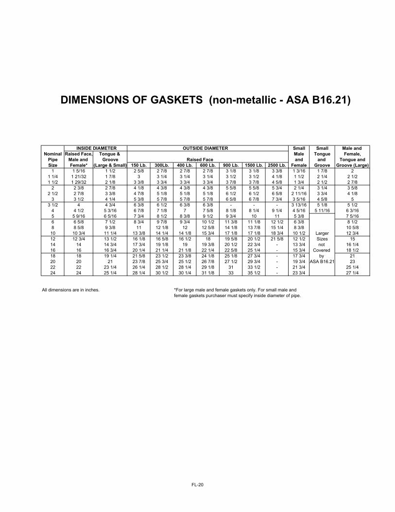
INSIDE DIAMETER OUTSIDE DIAMETER Small Small Male and Nominal Raised Face, Tongue & Male Tongue Female,
Pipe Male and Groove Raised Face and and Tongue andSize Female* (Large & Small) 150 Lb. 300Lb. 400 Lb. 600 Lb. 900 Lb. 1500 Lb. 2500 Lb. Female Groove Groove (Large)
1 1 5/16 1 1/2 2 5/8 2 7/8 2 7/8 2 7/8 3 1/8 3 1/8 3 3/8 1 3/16 1 7/8 21 1/4 1 21/32 1 7/8 3 3 1/4 3 1/4 3 1/4 3 1/2 3 1/2 4 1/8 1 1/2 2 1/4 2 1/21 1/2 1 29/32 2 1/8 3 3/8 3 3/4 3 3/4 3 3/4 3 7/8 3 7/8 4 5/8 1 3/4 2 1/2 2 7/8
2 2 3/8 2 7/8 4 1/8 4 3/8 4 3/8 4 3/8 5 5/8 5 5/8 5 3/4 2 1/4 3 1/4 3 5/82 1/2 2 7/8 3 3/8 4 7/8 5 1/8 5 1/8 5 1/8 6 1/2 6 1/2 6 5/8 2 11/16 3 3/4 4 1/8
3 3 1/2 4 1/4 5 3/8 5 7/8 5 7/8 5 7/8 6 5/8 6 7/8 7 3/4 3 5/16 4 5/8 53 1/2 4 4 3/4 6 3/8 6 1/2 6 3/8 6 3/8 - - - 3 13/16 5 1/8 5 1/2
4 4 1/2 5 3/16 6 7/8 7 1/8 7 7 5/8 8 1/8 8 1/4 9 1/4 4 5/16 5 11/16 6 3/165 5 9/16 6 5/16 7 3/4 8 1/2 8 3/8 9 1/2 9 3/4 10 11 5 3/8 7 5/166 6 5/8 7 1/2 8 3/4 9 7/8 9 3/4 10 1/2 11 3/8 11 1/8 12 1/2 6 3/8 8 1/28 8 5/8 9 3/8 11 12 1/8 12 12 5/8 14 1/8 13 7/8 15 1/4 8 3/8 10 5/810 10 3/4 11 1/4 13 3/8 14 1/4 14 1/8 15 3/4 17 1/8 17 1/8 18 3/4 10 1/2 Larger 12 3/412 12 3/4 13 1/2 16 1/8 16 5/8 16 1/2 18 19 5/8 20 1/2 21 5/8 12 1/2 Sizes 1514 14 14 3/4 17 3/4 19 1/8 19 19 3/8 20 1/2 22 3/4 - 13 3/4 not 16 1/416 16 16 3/4 20 1/4 21 1/4 21 1/8 22 1/4 22 5/8 25 1/4 - 15 3/4 Covered 18 1/218 18 19 1/4 21 5/8 23 1/2 23 3/8 24 1/8 25 1/8 27 3/4 - 17 3/4 by 2120 20 21 23 7/8 25 3/4 25 1/2 26 7/8 27 1/2 29 3/4 - 19 3/4 ASA B16.21 2322 22 23 1/4 26 1/4 28 1/2 28 1/4 29 1/8 31 33 1/2 - 21 3/4 25 1/424 24 25 1/4 28 1/4 30 1/2 30 1/4 31 1/8 33 35 1/2 - 23 3/4 27 1/4
All dimensions are in inches. *For large male and female gaskets only. For small male and female gaskets purchaser must specify inside diameter of pipe.
DIMENSIONS OF GASKETS (non-metallic - ASA B16.21)
FL-20

d 1/2'' 5/8'' 3/4'' 7/8'' 1'' 1 1/8'' 1 1/4'' 1 3/8'' d 1 1/2'' 1 5/8'' 1 3/4'' 1 7/8'' 2''SCREWTHREADS SCREWTHREADS
UNC UP TO 1'' INCL. 13 11 10 9 8 8 8 8 UNC UP TO 1'' INCL. 8 8 8 8 88-UN OVER 1'' 8-UN OVER 1''
S MAX 22.22 26.97 31.75 36.52 41.27 46.02 50.8 55.57 S MAX 60.32 65.07 69.85 74.62 79.37S MIN 21.59 26.19 30.79 35.41 40.01 44.61 49.23 53.83 S MIN 58.43 63.02 67.72 72.24 76.84m MAX 12.80 16.02 19.25 22.47 25.7 28.93 31.77 35 m MAX 38.22 41.45 44.67 47.9 51.13m MIN 11.79 14.91 18.04 21.16 24.29 27.41 30.15 33.28 m MIN 36.4 39.53 42.65 45.78 48.9
L* WEIGHT IN KG PER 1.000 PIECES L* WEIGHT IN KG PER 1.000 PIECES(INCLUDING 2 NUTS) (INCLUDING 2 NUTS)
2 99.2 169.7 268.5 8 1/2 2804.52 1/4 104.2 178.1 280.5 8 3/4 2853.92 1/2 109.4 187.2 296.5 9 2903.42 3/4 114.5 195.2 305.6 9 1/4 2952.8
3 119.5 203.3 316.1 9 1/2 3002.2 3675.83 1/4 124.7 211.2 327.8 9 3/4 3051.7 3791.83 1/2 129.7 219.3 339.6 10 3101.1 1849.8 4589.93 3/4 134.8 227.4 351.5 509 10 1/2 3200 3965.8 4724.5
4 139.9 235.4 363.7 525.2 11 3298.8 4081.9 4859.14 1/4 243.5 376.1 541.4 11 1/2 3397.7 4197.9 4993.64 1/2 251.5 387.8 557.6 788.5 12 3496.6 4313.9 5128.2 6133.64 3/4 259.6 398.6 573.8 799.0 13 4546 5397.3 6442.6
5 276.6 410.3 589.2 809.8 14 4778 5666.4 6751.65 1/4 280.1 423.3 606.0 831.2 15 5935.6 7060.5 8061.85 1/2 283.6 434.4 622.2 852.3 1132.6 16 6204.7 7369.5 8413.35 3/4 291.6 445.7 638.5 874.4 1159.7 17 7678.4 8764.8
6 299.7 457.3 654.5 895.0 1187.4 18 7987.4 9116.46 1/4 307.9 469.2 670.5 916.1 1215.0 19 8296.3 9367.96 1/2 315.8 480.9 686.9 937.2 1242.0 20 8605.3 9819.46 3/4 323.8 492.6 703.2 958.5 1269.8
7 331.9 504.4 719.5 979.6 1296.8 1666.17 1/4 512.6 735.7 1000.4 1324.6 1700.87 1/2 528 761.9 1022.0 1351.8 1734.87 3/4 539.3 773.4 1043.0 1379.6 1468.9
8 551.5 784.0 1065.0 1406.4 1803.5 2267.98 1/4 563.3 800.3 1085.4 1433.4 1838.2 2301.48 1/2 1106.9 1461.4 1870.7 2343.68 3/4 1134.6 1906.9 2365.7
9 1149.4 1940.9 2427.4
*L(LENGTH OF STUDBOLT) IS THE LENGTH OF FIRST THREAD.(WITHOUT POINTS).
STUD BOLTS WITH 2 HEXAGONAL NUTS UNC/8-UN
FL-21