fittings api 1104
DESCRIPTION
API 1104TRANSCRIPT
Dec. 1997
IPS-M-PI-150
This Standard is the property of Iranian Ministry of Petroleum. All rights are reserved to the owner. Neither whole nor any part of this document may be disclosed to any third party, reproduced, stored in any retrieval system or transmitted in any form or by any means without the prior written consent of the Iranian Ministry of Petroleum.
MATERIAL STANDARD
FOR
FLANGES AND FITTINGS
ORIGINAL EDITION
DEC. 1997
Dec. 1997
IPS-M-PI-150
1
0. INTRODUCTION
This Standard consists of Two Parts as follows:
Part I: Steel Pipe Flanges and Orifice Flanges
Part II: Steel Pipe Fittings
Throughout this Standard where a reference standard(s) is supplemented, the clause or section numbering of reference standard(s) has been used in each paragraph. Numberings which are not noted in the reference standard(s) are related to clause or section added to the reference standard(s).
Dec. 1997
IPS-M-PI-150
2
1. GENERAL DEFINITIONS
Throughout this Standard in supplementing reference standard(s) the following definitions shall hold:
Sub. (Substitution) The supplemented standard clause is deleted and replaced by a new clause.
Del. (Deletion) The supplemented standard clause is deleted without any replacement.
Add. (Addition) A new clause with a new number is added.
Mod. (Modification) Part of the supplemented standard clause is modified and/or a new statement or comment is added to that clause.
Purchaser
The party or parties entering into a contract or agreement to purchase flange(s) and / or fitting (s) in accordance with the requirements of this Standard and specially referred to as Company.
Company
Refers to one of the related and/or affiliated companies of the Iranian Ministry of Petroleum such as:
a) National Iranian Oil Company (NIOC)
b) National Iranian Gas Company (NIGC)
c) National Petrochemical Company (NPC)
Supplier/Vendor
Refers to person(s) or party(ies) entering into a contract or agreement to supply and/or fabricate the material in accordance with the requirements of this Standard.
Manufacturer
The party that manufactures or produces flange(s) and / or fitting (s) covered by this Standard.
Inspector
The representative of the Purchaser who is entrusted with inspection of products and production records and observance of production operations and quality control tests.
Dec. 1997
IPS-M-PI-150
This Standard is the property of Iranian Ministry of Petroleum. All rights are reserved to the owner. Neither whole nor any part of this document may be disclosed to any third party, reproduced, stored in any retrieval system or transmitted in any form or by any means without the prior written consent of the Iranian Ministry of Petroleum.
PART I
STEEL PIPE FLANGES AND ORIFICE FLANGES
Dec. 1997
IPS-M-PI-150/1
4
CONTENTS : PAGE No.
1. SCOPE ............................................................................................................................................ 5
2. REFERENCES ................................................................................................................................ 5
3. DEFINITIONS AND TERMINOLOGY ............................................................................................. 6
4. ABBREVIATIONS........................................................................................................................... 7
5. UNITS .............................................................................................................................................. 7
6. SECTION A: STEEL FLANGES IN SIZES DN 15 (NPS ½) TO DN 600 (NPS 24) ............................................................................... 7
7. SECTION B: STEEL FLANGES IN SIZE DN 650 (NPS 26) TO DN 1500 (NPS 60) .......................................................................... 11
8. SECTION C: ORIFICE FLANGES.............................................................................. 12
APPENDICES:
APPENDIX A SUPPLEMENTARY COMMENTARY................................................... 14

Dec. 1997
IPS-M-PI-150/1
5
1. SCOPE
This Part of the Standard covers minimum requirements for the procurement of steel flanges in sizes DN 15 (NPS ½) through DN 1500 (NPS 60) and also orifice flanges. The flanges shall be manufactured according to the following standards except for supplement thereof.
a) Flanges DN 15 (NPS ½) to DN 600 (NPS 24) as per ASME/ANSI B 16.5.
b) Flanges DN 650 (NPS 26) to DN 1500 (NPS 60) as per MSS-SP-44.
c) Orifice flanges as per ASME/ANSI 16.36-1988.
Cast iron and bronze flanges are not covered by this Standard.
2. REFERENCES
Throughout this Standard the following dated and undated standards/codes are referred to. These referenced documents shall, to the extent specified herein, form a part of this standard. For dated references, the edition cited applies. The applicability of changes in dated references that occur after the cited date shall be mutually agreed upon by the Company and the Vendor. For undated references, the latest edition of the referenced documents (including any supplements and amendments) applies.
API (AMERICAN PETROLEUM INSTITUTE)
API Standard 601 "Metallic Gaskets for Raised-Face Pipe Flanges and Flanged Connections (Double-Jacketed Corrugated and Spiral Wound)"
API Spec. 6A "Specification for Valves and Wellhead Equipment"
ASME (AMERICAN SOCIETY OF MECHANICAL ENGINEERS)
Section VIII division 1 "BPV Code for Pressure Vessel"
ASME / (AMERICAN SOCIETY OF MECHANICAL ENGINEERS /
ANSI AMERICAN NATIONAL STANDARD INSTITUTE)
B 1.20.1 "Pipe Threads, General Purpose"
ANSI - B 16.1 "Cast Iron Pipe Flanges and Flanged Fitting, Class 25, 125, 250, and 800"
B 16.5 "Pipe Flanges and Flanged Fittings"
ANSI - B 16.11 "Forged Steel Fittings, Socket-Welding and Threaded"
B 16.20 "Ring Joint Gaskets and Grooves for Steel Pipe Flanges"
B 16.21 "Non-Metallic Flat Gaskets for Pipe Flanges"
B 16.36 "Orifice Flanges"
ASTM (AMERICAN SOCIETY FOR TESTING AND MATERIALS)
A 105 "Specification for Forgings, Carbon Steel, for Piping Components"
A 181 "Specification for Forgings, Carbon Steel, for General-Purpose Piping"
A 182 "Specification for Forged or Rolled Alloy-Steel Pipe
Dec. 1997
IPS-M-PI-150/1
6
Flanges, Forged Fittings, and Valves and Parts for High-Temperature Services"
A 350 "Specification for Forgings Carbon and Low Alloy Steel, Requiring Notch Toughness Testing for Piping Components"
A 387 "Specification for Pressure Vessel Plates, Alloy Steel Chromium Molybdenum"
A 694 "Specification for Forgings, Carbon and Alloy Steel, for Pipe Flanges, Fittings, Valves, and Parts for High-Pressure Transmission Services"
IPS (IRANIAN PETROLEUM STANDARDS)
IPS-D-PI-144 "Insulated Flange Detail"
IPS-M-TP-750/15 "Specification for Flange Insulation Kit"
MSS (MANUFACTURERS STANDARDIZATION SOCIETY)
SP-6 "Standard Finishes for Contact Faces of Pipe Flanges and Connecting- End Flanges of Valves and Fittings"
SP-44 "Steel Pipeline Flanges"
3. DEFINITIONS AND TERMINOLOGY
For the purpose of This Part of the Standard the following definitions and terms shall hold.
3.1 Flange Edge
The reference plane, coincident with the front of a flange, from which the height of any type of flange facing and also the minimum flange thickness is measured.
3.2 Flange Thickness
The distance from the flange edge to the back face of a flange or, if the bolt holes are spot-faced, from the flange edge to the spot-facing.
3.3 Flange Facing
The profile of the connecting end of a flange. It is beyond the flange edge, except for a flange of PN 20 (class 150) or PN 50 (class 300) having a 1.6 mm high raised facing, in which case the raised facing is formed by cutting into the minimum flange thickness.
3.4 Contact Surface
That part of a flange facing upon which the gasket is actually compressed. In the case of flanges of PN 20 (class 150) and PN 50 (class 300) having 1.6 mm high raised facing, and in all nominal pressures (classes) having female and groove facings, the contact surface is coincident with the flange edge as defined above.
"Contact Surface" is not applicable to ring-joint facing.
Dec. 1997
IPS-M-PI-150/1
7
3.5 Full-Faced
Applies only to female, groove and ring-joint facings and defines the resultant profile when the raised portion of such facing is extended to the full diameter of the flange.
4. ABBREVIATIONS
AARH = "Arithmetical Average Roughness Height"
CAF = "Compressed Asbestos Fibre"
NB = "Nominal Bore"
PTFE = "Poly Tetra Fluoro Ethylene"
RF = "Raised Face"
RMS = "Root Mean Square"
RTJ = "Ring Type Joint"
SW = "Spiral Wound"
5. UNITS
This Standard is based on International System of Units (SI), except where otherwise specified.
6. SECTION A: STEEL FLANGES IN SIZES DN 15 (NPS ½) TO DN 600 (NPS 24)
This Section is supplement to reference standard ASME/ANSI B 16.5 "Pipe Flanges and Flanged Fittings".
1.4 Those flanges which are not covered by ASME/ANSI B.16.5 shall be calculated in accordance with ASME Section VIII Division 1. (Add.)
3.4 Pipe flanges of the following nominal diameters are specified:
DN 15 (NPS ½), DN 20 (NPS ¾), DN 25 (NPS 1), DN 32 (NPS 1¼), DN 40 (NPS 1½), DN 50 (NPS 2), DN 65 (NPS 2½), DN 80 (NPS 3), DN 90 (NPS 3½), DN 100 (NPS 4), DN 125 (NPS 5), DN 150 (NPS 6), DN 200 (NPS 8), DN 250 (NPS 10), DN 300 (NPS 12), DN 350 (NPS 14), DN 400 (NPS 16), DN 450 (NPS 18), DN 500 (NPS 20) and DN 600 (NPS 24).
Note:
The DN 90 (NPS 3½) not specified for Nominal Pressures PN 150 (class 900), PN 250 (class 1500) and PN 420 (class 2500) sizes over DN 300 (NPS 12) are not specified for PN 420 (class 2500) . (Add.)
3.5 The use of sizes DN 32 (NPS 1¼), DN 65 (NPS 2½), DN 90 (NPS 3½) and DN 125 (NPS 5) should be avoided where possible. (Add.)
4.1.2 Material
Add to the end of clause (a).
When the minimum yield strength of the hub portion of flange is less than that specified for maching pipe, the marking shall also include the grade of the material of the pipe to be matched with the flange. (Mod.)
Dec. 1997
IPS-M-PI-150/1
8
4.1.3 Rating class
The marking shall include the both applicable nominal pressure and pressure rating class PN 20 (150), PN 50 (300), PN 68 (400), PN 100 (600), PN 150 (900), PN 250 (1500) and PN 420 (2500). (Sub.)
4.1.4 Substitute IPS-M-PI-150 with B.16 in the first line of the clause. (Mod.)
4.1.8 Thread identification
When flanges are not screwed to ANSI/ASME B 1.20.1 they shall be marked to indicate the type of thread used. The marking shall be cast or stamped on the flanges. (Add).
4.1.9 Omission of marking
On flanges of such size as will not permit full marking, the marking may be omitted, with the approval of the Purchaser, to the degree which conditions require in the following sequence:
1) Material
2) Grade of maching pipe
3) Size
4) Class rating
5) Thread identification
6) Standard designation
7) Manufacturers name or trade mark (Add.)
5. MATERIAL
5.1 General
Flanges shall be forged in accordance with material specifications ASTM A 105, A 181, A 182, A 350, A 387, A 694 and nickel base alloys. Forging to other standards may be used only subject to the approval of the Purchaser. Slip-on flanges made from plate shall not be used except for low pressure duties and for reducing flanges and then only subject to the approval of the Purchaser. These materials are listed in Table 1A.
Note:
Columns related to castings in Table 1A shall be omitted. (Sub.)
5.1.2 In Figs. 12, 13 and 14, if t1, t2 or sum t1 + t2 exceeds 0.5t, the material of the flange shall be substituted by a material with higher yield strengths (e.g. ASTM A 694). Flange material with yield strengths 331 mPa (48 ksi) and higher shall be killed steel (A 350 gr LF-1 or gr LF-2). (Add.)
5.1.3 All flanges shall be furnished in a heat-treated condition. Heat treatment shall consist of normalizing, normalizing and tempering, or quenching and tempering. (Add.)
5.3.4 Bolting to gray cast iron flanges
This clause shall be deleted. (Del.)
Dec. 1997
IPS-M-PI-150/1
9
5.4 Gaskets (Sub.)
Different material used for supply of gaskets and joint rings for use with bolted flanged joints, primarily in piping systems and for connections of piping to equipment is covered in this section.
5.4.1 Health, safety and environmental requirements
In this respect, consideration shall be given to important information given in page IV of API Std 601 edition 1988.
5.4.1.1 Material safety data sheets shall be available for all jointing materials.
5.4.1.2 The supplier shall provide details of any necessary protective equipment to be used when handling jointing materials.
Any jointing Containing Compressed Asbestos Fibre (CAF) shall be suitably Packaged and labeled both on the packaging and gasket materials "Contains Asbestos".
5.4.2 Non-metallic flat gaskets
Non-metallic flat gaskets for flanges covered in this Standard shall be in accordance with ANSI B.16.21.
5.4.2.1 Non-metallic flat gaskets for raised face flanges shall be either self-centering within the flange bolts or full face type.
5.4.2.2 Gaskets with outside diameter matching the raised face of flanges should not be used.
5.4.2.3 Full face gaskets are recommended for raised face flanges smaller than DN 50 (2 inch nominal Bore) to avoid potential problems of incorrect size gaskets being fitted. For DN 50 (2 inch NB) and above self-centering gaskets shall be used for raised face flanges.
5.4.2.4 Non-metallic flat gaskets for use with flat face flanges should be full face.
5.4.3 Metallic and semi metallic gasket and joint rings
5.4.3.1 Metal jacketed gaskets
Metal jacketed gaskets for flanges covered in this Standard shall be of the double jacket type and shall comply with the requirements and dimensions of API 601.
5.4.3.2 Spiral wound gaskets
Spiral wound gaskets for flanges covered in this Standard shall comply with the requirements and dimensions of API 601.
5.4.4 Solid metal joint rings
5.4.4.1 Solid metal joint rings for wellhead equipment to API 6A shall comply with the requirements of API 6A.
5.4.4.2 When specified, Monel 400 joint rings shall have a maximum Brinell Hardness of 135 and be identified by the material symbol M 400.
5.4.4.3 Solid metal joint rings for piping and pipeline flanges to this Standard shall comply with ANSI B.16.20.
5.4.5 The data sheet in the next page covers joint requirements.
5.4.6 Appendix "A" serves as a guideline for selection of gasket from view point of "Material and

Dec. 1997
IPS-M-PI-150/1
10
Design".
DATA SHEET Project: Enq./order No. Service:
Pressure Rating:
Flange Std.
Design Temp.
Gasket Std.
Gasket Type
Material Flat Joints: Basic Material Graphited Jacket/Envelope Spiral Wound: Filler/Winding Centering Ring Inner Ring Metallic Joint Rings: Material Hardness
Dimensions: Nominal Size Full Face Inside Bolts Ring No/Type (oval or Oct) Thickness Additional Requirements: Data Sheet No. Date Rev.
9. INSULATING FLANGE
Insulating flanges shall be in accordance with this Standard specification for flanges except that bolt
holes shall be"16
1 larger for "321 thick insulating sleeves. Flanges shall be drilled in pair and
match-marked for optimum bolt hole alignment and to have anti-corrosion coating. Reference shall be made to standard drawing IPS-D-PI-144 and IPS-M-TP-750/9 "Specification for Flange Insulation Kit". (Add.)
Dec. 1997
IPS-M-PI-150/1
11
10. INSPECTION AND DEFECTS (Add.)
10.1 General Requirements
The Purchaser or his representative shall have free access, at all reasonable times to those parts of the manufacturer’s works engaged in the fabrication, production and testing of flanges under his contract, and shall be at liberty to witness the tests and inspect at any stage of the manufacturing the materials and equipment used in the manufacturing process.The manufacturer/supplier shall give both the Purchaser and his representative at the address stated on the purchase order at least two month’s advance notice before starting to manufacture the flanges.
The manufacturer shall supply the material, tools and equipment required for testing and inspection; the manufacturer shall apply and prepare the necessary test pieces and also supply the labor and appliances for such testing as may be carried out on his premises in accordance with standard. In the absence of facilities at his own works for making the prescribed tests the manufacturer shall arrange for the tests to be carried out elsewhere.
10.2 Defects
Flanges shall be free of any surface or internal defects in the finished condition.
Flanges which show defects on inspection or which prove defective in use shall be rejected and the manufacturer/ supplier so noticed. Any defective flange shall be replaced by the manufacturer/supplier and the manufacturer/supplier shall bear the full costs of the replacement.
7. SECTION B: STEEL FLANGES IN SIZE DN 650 (NPS 26) TO DN 1500 (NPS 60)
This section is supplement to reference standard MSS-SP-44 (steel pipeline flanges).
Substitute the following sentence with sentence between parenthesis in third line of clause 1.1 (by reference to section A of this Standard).
1.1.1 Dimensional requirements for sizes DN 600 (NPS 24) and smaller are provided by reference to section A of this Standard. When such flanges meet all other stipulations of this section of standard, they shall be considered as complying therewith. (Sub.)
3.3.4 Delete this clause. (Del.)
5.1.1 Class 150 flange drilling templates are the same as section A of this Standard and class 125 of ANSI/ASME B.16.1 (Mod.)
5.1.2 Delete first three lines of this clause. (Mod.)
5.2 Flange Ring Design
The outside diameter and flange thickness are designed in accordance with Appendix II of Division I of Section VIII of ASME boiler and pressure vessel code and flange ring shall have sufficient pressure capacity for the service based on its strength in the normalized condition. (Sub. with two first sentences)
5.3.1
a) When the mechanical (minimum yield strength) properties of all sections of the flanges are equal to or higher than those of the pipe to be mached, hub dimensions shall be designed in accordance with Appendix II of Section VIII of ASME "Boiler and Pressure Vessel Code". (Sub.)
b) Delete last sentence of this Clause. (Mod.)
Dec. 1997
IPS-M-PI-150/1
12
5.6 Bolt Holes
Bolt holes shall be drilled perpendicular to the flange face and shall be equally spaced. Bolt holes in an integral flange of a flanged valve or fitting shall straddle the centerline. (Sub.)
6.2 (Del.)
10.1 Facings
Delete second and fifth lines. (Mod.)
10.2 Flange Thickness
Tolerances for flange thickness shall be to +0.19 inch - zero. (Sub.)
10.3.1 Delete fourth line. (Mod.)
10.3.2 + 0.12 inch
- 0.06 inch (Sub. with fourth and fifth lines)
10.4 Delete third line. (Mod.)
10.5.3 Delete third line. (Mod.)
10.6 Delete this Clause. (Del.)
Tables 4 to 10
Delete dimension for lines smaller than 26 inches in above tables. (Mod.)
ANNEX A
The title of second column of table in this Annex shall be changed to cover sizes 26-36 inch inclusive. (Mod.)
8. SECTION C: ORIFICE FLANGES
This section is supplement to reference standard ASME/ANSI B.16.36-1988 "Orifice Flanges".
3.2 Bolting
Material shall be in accordance with ASME/ANSI B.16.5, but flanges shall be supplied without flange bolting. (Mod.)
3.3 Plugs
All orifice taps shall be furnished with solid forged round head plugs (per ANSI B.16.11) of the same basic metallurgy as the flanges. (Sub.)
6. FLANGE FACING FINISH
Where a "Smooth Finish" facing is specified in the item description, the gasket contact surface shall be 100-150 AARH in accordance with MSS-SP-6.100-150 RMS is also acceptable. (Sub.)
7.3 Flanges shall be supplied without gaskets. (Add.)
Dec. 1997
IPS-M-PI-150/1
13
8.3 Pipe Connection
Flanges shall have AGA standard tapping as follows.
8.3.1 DN 15 (½ NPS) for PN 50, 68, and 100 (ANSI Rating 300, 400 and 600) flanges. (Sub.)
8.3.2 DN 20 (¾ NPS) for PN 150, 250 and 420 (ANSI Rating 900, 1500 and 2500) flanges. (Sub.)
8.4 Orifice tap drill holes and dimensions shall be to AGA catalog No. X 50169. (Add.)
8.5 Orifice tapping shall have female taper pipe threads conforming to ANSI/ASME B 1.20.1. (Add.)
Dec. 1997
IPS-M-PI-150/1
14
APPENDICES
APPENDIX A
SUPPLEMENTARY COMMENTARY
A.1 Bolted Flanged Joints
The suitability of a particular gasket or joint ring must be established from consideration of the type and material of the flanges, flange facing and finish, quantity and type of bolting, service conditions, any specific requirements regarding leak tightness for Health, Safety or Environmental reasons, and any limitations on gasket materials e.g., use of asbestos.
Due consideration should be given to control of fugitive emissions from the completed joint when selecting gasket. For many applications joint selection will be specified in the piping or vessel specification.
Proper bolting up procedures, using appropriate equipment, are essential to ensure the correct and satisfactory joint assembly.
A.2 Guidance on Selection of Joint Type and Materials
The following guidance applies where pre-selection has not been carried out.
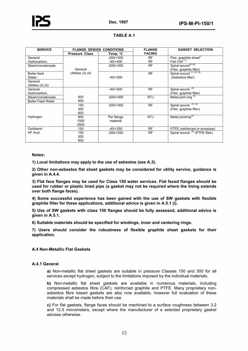
Table A.1 summarizes suitable jointing for piping flanges for various services. Use of jointing outside the ranges given may be acceptable but should be evaluated for each application. Additional guidance is given in sections A.4, A.5 and A.6.
Joint design maximum and minimum temperatures should be taken to be the same as the process design temperatures.
A.3 General Comments on Asbestos Usage
Before asbestos is selected as jointing or filler material, any restrictions imposed by health or environmental regulations in the country of use should be established. However, any perception of increased health risk in handling the material should be balanced against proven plant operational safety in those applications identified in this Standard.
Asbestos in whatever form must be handled, stored and disposed of under specific site procedures which may be based on Company Occupational Health guidance.
Disposal costs should be assessed as part of the whole life cost in selecting appropriate materials.
Dec. 1997
IPS-M-PI-150/1
15
TABLE A.1
FLANGE DESIGN CONDITIONS SERVICE
Pressure Class Temp. °C FLANGE FACING
GASKET SELECTION
General Hydrocarbon,
-200/+500 -40/+400
RF RF
Flex. graphite sheet(7Flat CAF (1)
Steam/condensate -200/+500 RF Spiral wound(5) (6)
(Flex. graphite filler) Boiler feed Water, General Utilities (3) (4)
General Utilities (3) (4)
-40/+500 RF Spiral wound (1) (5) (6)
(Asbestos filler)
General Hydrocarbon,
-40/+500 RF Spiral wound (6)
(Flex. graphite filler) Steam/condensate Boiler Feed Water
600 900
-200/+500 RTJ Metal joint ring (4)
150 300 600
-200/+500 RF Spiral wound (5) (6)
(Flex. graphite filler) Hydrogen
900 1500 2500
Per flange material
RTJ Metal jointring(4)
150 -40/+250 RF PTFE (reinforced or envelope) Oxidisers/ HF Acid 150
300 600
-200/+250 RF Spiral wound (6) (PTFE filler)
Notes:
1) Local limitations may apply to the use of asbestos (see A.3).
2) Other non-asbestos flat sheet gaskets may be considered for utility service, guidance is given in A.4.4.
3) Flat face flanges may be used for Class 150 water services. Flat faced flanges should be used for rubber or plastic lined pipe (a gasket may not be required where the lining extends over both flange faces).
4) Some successful experience has been gained with the use of SW gaskets with flexible graphite filler for these applications, additional advice is given in A.5.1 (i).
5) Use of SW gaskets with class 150 flanges should be fully assessed, additional advice is given in A.5.1.
6) Suitable materials should be specified for windings, inner and centering rings.
7) Users should consider the robustness of flexible graphite sheet gaskets for their application.
A.4 Non-Metallic Flat Gaskets
A.4.1 General
a) Non-metallic flat sheet gaskets are suitable in pressure Classes 150 and 300 for all services except hydrogen, subject to the limitations imposed by the individual materials.
b) Non-metallic flat sheet gaskets are available in numerous materials, including compressed asbestos fibre (CAF), reinforced graphite and PTFE. Many proprietary non-asbestos fibre based gaskets are also now available, however full evaluation of these materials shall be made before their use.
c) For flat gaskets, flange faces should be machined to a surface roughness between 3.2 and 12.5 micrometers, except where the manufacturer of a selected proprietary gasket advises otherwise.
Dec. 1997
IPS-M-PI-150/1
16
A.4.2 Compressed asbestos fibre flat sheet gaskets
a) Compressed asbestos fibre (CAF) flat gasket sheet material has a long successful operating history on general use over the temperature range -40°C to +400°C. As the exact minimum and maximum temperatures depend on the selection of filler and binder materials, any proposed use outside this range should be assessed with the manufacturer concerned.
b) Pre-cut gaskets should be specified. Cutting of gaskets should be avoided.
c) Unless required with special properties, CAF gaskets should be specified oil resistant to be suitable for oilrefinery and chemical plant duty.
Gaskets should be specified to an appropriate standard when required for aviation fuels, di-ester type synthetic lubrication oils and similar duties where control of swell characteristics is required.
d) CAF flat gaskets should be supplied graphited on both sides to help sealing and subsequent removal of the gasket, except where graphite may promote corrosion of the flanges.
Ungraphited gaskets should be specified for:
i) Austenitic stainless steel flanges on aqueous duties.
ii) Aggressive water duties, e.g. where cement lined pipe is used.
e) CAF flat gaskets should be specified 1.5 mm thick for flanges up to 24 inch NB and 3.00 mm thick for larger flanges. As a general rule, the thinner the gasket the better, but above 24 inch NB, thin gaskets may be difficult to handle 1.5 mm gaskets are acceptable on larger sizes where they can be handled satisfactorily.
A.4.3 Reinforced flexible graphite flat gaskets
a) Flexible graphite flat gaskets have sealing characteristics which are as good as CAF gaskets. The applicable temperature range is -200°C to +500°C. However these gaskets are soft and prone to damage in handling.
Graphite sheet may be reinforced with one or two layers of thin metallic sheets or perforated metallic mesh normally from stainless steel or nickel. The reinforcing material should be appropriate to the service.
b) In oxidising environments (including ambient air) flexible graphite may be oxidised at temperatures above 500°C. Flexible graphite sheet gaskets should not be used above 500°C, unless totally enclosed in a reducing environment.
A.4.4 Non-asbestos fibre flat gaskets
a) Non-asbestos fibre gaskets shall be manufactured based on aramid, glass or carbon fibre using fillers and binder acceptable to purchaser. The manufacturer shall specify possibility of embrittlement versus temperature in service.
b) Any potential health risk of substitute fibre materials should be specified by manufacturer.
c) The manufacturer should specify the suitable thickness for the service concerned.
d) The gasket manufacturer shall specify jointing compounds to match the gasket characteristics.
e) Manufacturer shall specify resistance of gasket against oil for maximum chloride content of 100 ppm.
A.4.5 Rubber, elastomeric and polymeric flat gaskets - general
Advice of materials specialists and manufacturers should be sought when selecting and specifying
Dec. 1997
IPS-M-PI-150/1
17
these materials except for the application of PTFE which is given below:
a) Jointing materials for water services should not support Legionella growth.
b) Jointing materials for potable water must not taint the water.
A.4.6 PTFE flat gaskets
a) Manufacturer shall specify additive or method he intends to use for improvement of stress relaxation.
b) Manufacturer shall specify suitable temperature ranges for PTFE joints. (vergin PTFE as well as PTFE envelope or reinforced joints) for review and approval of the Purchaser.
A.5 Spiral Wound and Metal Jacketed Gaskets
A.5.1 Spiral wound (SW) gaskets
a) Manufacturer shall confirm suitability of the gasket for pressure rating, and service conditions specified in purchase order.
b) SW gaskets for use with standard flanges should be supplied with both outer and inner support rings in all cases where not fully constrained within a groove.
A.5.2 Metal jacketed gaskets
Manufacturer shall confirm suitability of jacket and filler material with process fluid and service conditions given in purchase order with due regard to requirements of API 601.
A.6 Solid Metal Joint Rings (RTJ)
a) This Section does not apply to flat solid metal joints which are normally specially designed.
b) Rings and groove faces must be free of imperfections.
c) Manufacturer shall confirm compatibility of material of joint ring with the flange material and process conditions.
d) Ring hardness should be less than flange hardness.
e) Metal joint rings to ANSI B 16.20 may be octagonal or oval. ANSI B 16.20 and API 6A type R gaskets are equivalent and interchangeable.
Dec. 1997
IPS-M-PI-150
This Standard is the property of Iranian Ministry of Petroleum. All rights are reserved to the owner. Neither whole nor any part of this document may be disclosed to any third party, reproduced, stored in any retrieval system or transmitted in any form or by any means without the prior written consent of the Iranian Ministry of Petroleum.
PART II
STEEL PIPE FITTINGS
Dec. 1997
IPS-M-PI-150/2
20
CONTENTS : PAGE No.
1. SCOPE .......................................................................................................................................... 21 2. REFERENCES .............................................................................................................................. 21 3. DEFINITIONS AND TERMINOLOGY ........................................................................................... 23 4. ABBREVIATIONS......................................................................................................................... 23 5. UNITS ............................................................................................................................................ 24 6. SECTION A:WROUGHT STEEL BUTT WELDING FITTINGS FORON-PLOT PIPING SYSTEMS........................................................................................................................................................... 24 7. SECTION B: HIGH TEST WROUGHT BUTT WELDING FITTINGS FOR OFF-PLOT PIPING SYSTEMS ........................................................................................................................... 28 8. SECTION C: WROUGHT AND CAST STAINLESS STEEL BUTT WELDING FITTINGS .... 35 9. SECTION D: WROUGHT STEEL BUTT WELDING SHORT RADIUS ELBOWS AND RETURNS........................................................................................................................................................... 45 10. SECTION E: CARBON STEEL AND ALLOY STEEL THREADED AND SOCKET WELDING FITTINGS .......................................................................................................................................... 45 11. SECTION F: WELDING OUTLET FITTINGS ............................................................................. 56 12. SECTION G: STEEL PIPE UNIONS (SOCKET-WELDING AND THREADED)........................ 73
Dec. 1997
IPS-M-PI-150/2
21
1. SCOPE
This Part of the Standard covers minimum requirements for the procurement of steel pipe fittings in sizes DN 15 (NPS ½) through DN 1200 (NPS 48). Fittings shall be manufactured according to the following standards except for supplements mentioned in the relevant paragraphs:
1.1 Wrought steel butt welding fittings as per ANSI/ASME B 16.9-1986 and MSS-SP-75 1988.
1.2 Wrought and cast stainless steel butt welding fittings as per MSS-SP-43 1982.
1.3 Wrought steel butt welding short radius elbows and returns as per ANSI/ASME B 16.28 1986.
1.4 Carbon steel and alloy steel threaded and socket-welding fittings as per ANSI/ASME B 16.11 1980 and MSS SP- 83 latest edition.
2. REFERENCES
Throughout this Standard the following standards and codes are referred to. The edition of these standards and codes that are in effect at the time of publication of this Standard shall, to the extent specified herein, form a part of this Standard.The applicability of changes in standards and codes that occur after the date of this Standard shall be mutually agreed upon by the Company and the Vendor.
ANSI / (AMERICAN NATIONAL STANDARD INSTITUTE /
ASME AMERICAN SOCIETY OF MECHANICAL ENGINEERS)
B 16.9 "Factory Made Wrought Steel Butt Welding Fittings"
B 16.11 "Forged Steel Fittings (Socket Welding and Threaded)"
B 16.25 "Butt Welding Ends"
B 16.28 "Wrought Steel Butt Welding Short Radius Elbow and Returns"
B 31.1 "Power Piping"
B 31.3 "Chemical Plant and Petroleum Refinery Piping"
B 36.10 "Welded and Seamless Wrought Steel Pipe"
ASME (AMERICAN SOCIETY OF MECHANICAL ENGINEERS)
Section IV "Heating Boilers"
Section VIII "Pressure Vessels"
Section IX "Welding and Brazing Qualifications"
ASTM (AMERICAN SOCIETY FOR TESTING AND MATERIALS)
A 105 "Specification for Forgings, Carbon Steel, for Piping Components"
A 106 "Specification for Seamless Carbon Steel Pipe for High Temperature Service"
A 181 "Specification for Forgings, Carbon Steel, for General Purpose Piping"
A 182 "Specification for Forged or Rolled Alloy-Steel Pipe Flanges, Forged Fittings, and Valves and Parts for High-Temperature Service"
A 234 "Specification for Piping Fittings of Wrought Carbon Steel and Alloy Steel fo Moderate and Elevated Temperatures"
Dec. 1997
IPS-M-PI-150/2
22
A 276 "Specification for Stainless and Heat Resisting Steel Bars and Shapes"
A 312 "Specification for Seamless and Welded Austenitic Stainless Steel Pipe"
A 333 "Specification for Seamless and Welded Steel Pipe for Low Temperature Service"
A 334 "Specification for Seamless and Welded Carbon and Alloy Steel Tubes for Low Temperature Service"
A 335 "Specification for Seamless Ferritic Alloy Steel Pipe for High Temperature Service"
A 350 "Specification for Forging, Carbon and Low Alloy Steel, Requiring Notch Toughness Testing For Piping Components"
A 351 "Specification for Steel Casting, Austenitic for High Temperature Service"
A 387 "Specification for Pressure Vessel Plates Alloy Steel, Chromium-Molybdenum"
A 400 "Practice for Steel Bars, Selection Guide, Composition and Mechanical Properties"
A 403 "Specification for Wrought Austenitic Stainless Steel Piping Fittings"
A 420 "Specification for Piping Fittings of Wrought Carbon Steel and Alloy Steel for Low Temperature Service"
A 515 "Specification for Pressure Vessel Plates, Carbon Steel, for Intermediate and Higher Temperature Service"
A 516 "Specification for Pressure Vessel Plates, Carbon Steel for Moderate and Lower Temperature Service"
A 576 "Specification for Steel Bars, Carbon, Hot Wrought Special Quality"
B 164 "Specification for Nickel-Copper Alloy, Rod, Bar and Wire"
E 92 "Test Method for Vickers Hardness of Metallic Materials"
API (AMERICAN PETROLEUM INSTITUTE)
API-5L "Specification for Line Pipe"
BS (BRITISH STANDARD INSTITUTION)
BS-131 Part 2 "The Charpy V-Notch Impact Test on Metals"
BS 1501 "Steels for Pressure Purposes: Plates"
BS 1502 "Specification for Steels for Fired and Unfired Pressure Vessels: Sections and Bars"
BS 1503 "Specification for Steel Forging (Including Semifinished Forged Products) for Pressure Purposes"
BS 1600 "Specification for Dimensions of Steel Pipe for the Petroleum Industry"
BS 2600 "Radiographic Examination of Fusion Welded Butt Joints in Steel"
BS 2910 "Methods for Radiographic Examination of Fusion Welded Circumferential ButtJoints in Steel Pipes"
Dec. 1997
IPS-M-PI-150/2
23
BS 2926 "Specification for Chromium and Chromium-Nickel Steel Electrods fro Manual Metal Arc Welding"
BS 5383 "Specification for Material Identification of Steel, Nickel Alloy and Titanium Alloy Tubes by Continuous Character Marking and Color Coding of Steel Tubes"
BS 6072 "Method for Magnetic Particle Flaw Detection"
ISO (INTERNATIONAL STANDARD ORGANIZATION)
ISO-10474 "Steel and Steel Product, Inspection Documents”
Type 5.1 B&C
MIL (US MILITARY STANDARD)
MIL-C-15726 E "Copper Nickel Alloy Rod, Flat Products (Flat Wire, Strip, Sheet, Bar and Plate) and Forgings"
MSS (MANUFACTURERS STANDARDIZATION SOCIETY)
SP-43 "Wrought Stainless Steel Butt Welding Fittings"
SP-75 "Specification for High Test Wrought Butt Welding Fittings"
SP-83 "Steel Pipe Unions, Socket Welding and Threaded"
NACE (NATIONAL ASSOCIATION OF CORROSION ENGINEERS)
MR- 0175 "Material Requirements Sulfide Stress Cracking Resistant Metallic
Materials for Oil Field Equipment"
SIS (STANDARDIZERINGS KOMMISSIONEN I SVERIGE)
SIS 055900 "Swedish Standards Institution Practice-Surface Preparation Standard for Painting Steel Surface"
3. DEFINITIONS AND TERMINOLOGY
For the Purpose of this part of the Standard the following definitions and terms shall hold.
3.1 Killed Steel
Thoroughly deoxidized steel for example by addition of aluminum or silicon, in which the reaction between carbon and oxygen during solidification is suppressed.
3.2 Wrought Steel
Steel that has been mechanically worked after casting.
4. ABBREVIATIONS
HAZ "Heat Affected Zone"
HV 10 "Hardness Vickers 10"
Dec. 1997
IPS-M-PI-150/2
24
XS "Extra Strong"
XXS "Double Extra Strong"
5. UNITS
This Standard is based on International System of Units (SI), except where otherwise specified.
6. SECTION A:WROUGHT STEEL BUTT WELDING FITTINGS FORON-PLOT PIPING SYSTEMS
This Section is supplement to reference standard ASME/ANSI B 16.9 (1986).
3. SIZE AND SIZE IDENTIFICATION
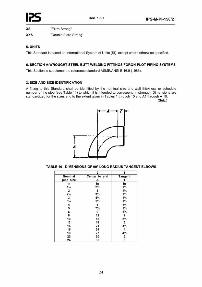
A fitting to this Standard shall be identified by the nominal size and wall thickness or schedule number of the pipe (see Table 11) to which it is intended to correspond in strength. Dimensions are standardized for the sizes and to the extent given in Tables 1 through 10 and A1 through A 10. (Sub.)
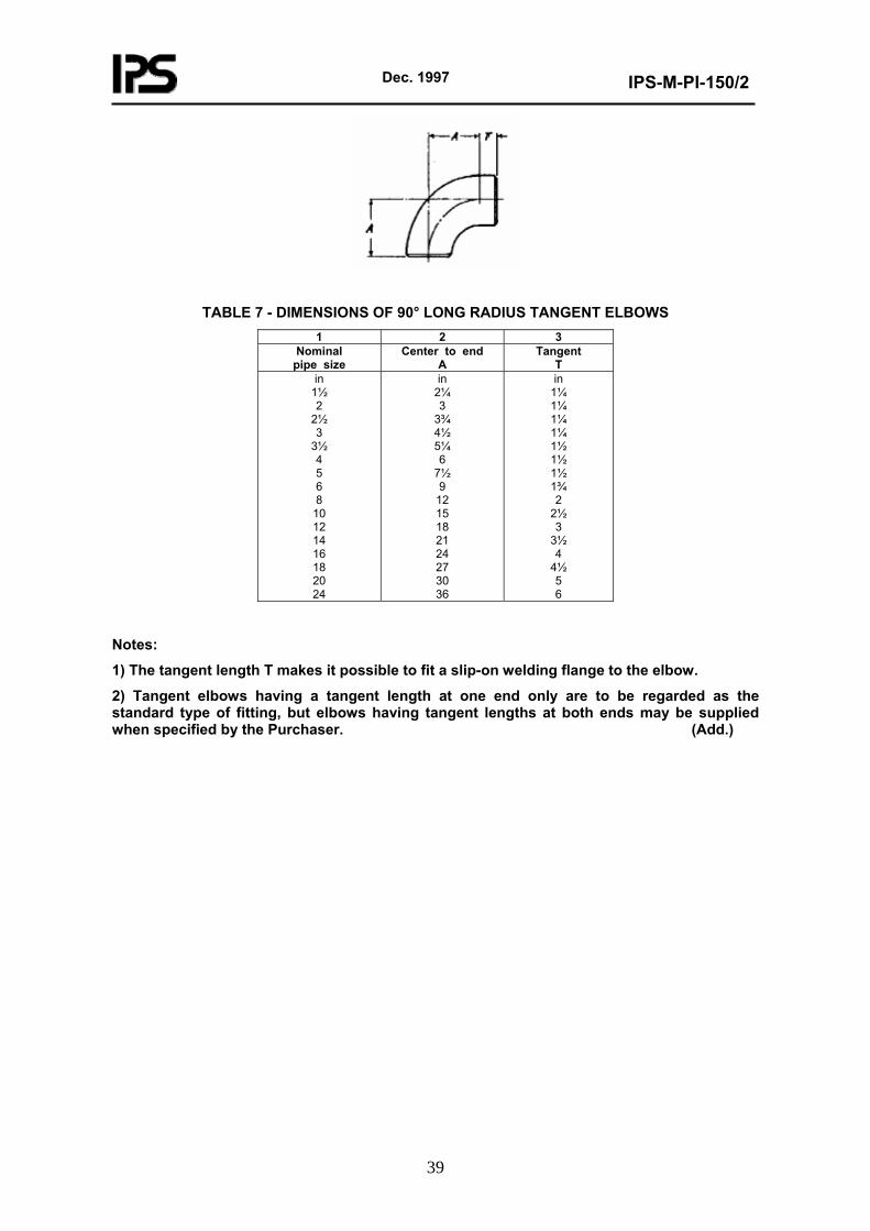
TABLE 10 - DIMENSIONS OF 90° LONG RADIUS TANGENT ELBOWS
1 2 3 Nominal
pipe size Center to end
A Tangent
T in 1½ 2
2½ 3
3½ 4 5 6 8
10 12 14 16 18 20 24
in 2¼ 3
3¾ 4½ 5¼ 6
7½ 9
12 15 18 21 24 27 30 36
in 1¼ 1¼ 1¼ 1¼ 1½ 1½ 1½ 1¾ 2
2½ 3
3½ 4
4½ 5 6
Dec. 1997
IPS-M-PI-150/2
25
Notes:
1) The tangent length T makes it possible to fit a slip-on welding flange to the elbow.
2) Tangent elbows having a tangent length at one end only are to be regarded as the standard type of fitting, but elbows having tangent lengths at both ends may be supplied when specified by the Purchaser. (Add.)
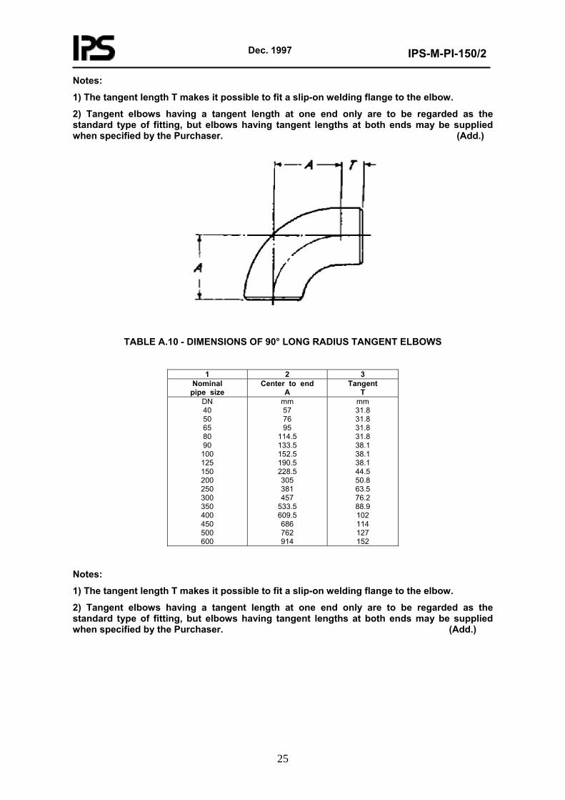
TABLE A.10 - DIMENSIONS OF 90° LONG RADIUS TANGENT ELBOWS
1 2 3
Nominal pipe size
Center to end A
Tangent T
DN 40 50 65 80 90
100 125 150 200 250 300 350 400 450 500 600
mm 57 76 95
114.5 133.5 152.5 190.5 228.5 305 381 457
533.5 609.5 686 762 914
mm 31.8 31.8 31.8 31.8 38.1 38.1 38.1 44.5 50.8 63.5 76.2 88.9 102 114 127 152
Notes:
1) The tangent length T makes it possible to fit a slip-on welding flange to the elbow.
2) Tangent elbows having a tangent length at one end only are to be regarded as the standard type of fitting, but elbows having tangent lengths at both ends may be supplied when specified by the Purchaser. (Add.)
Dec. 1997
IPS-M-PI-150/2
26
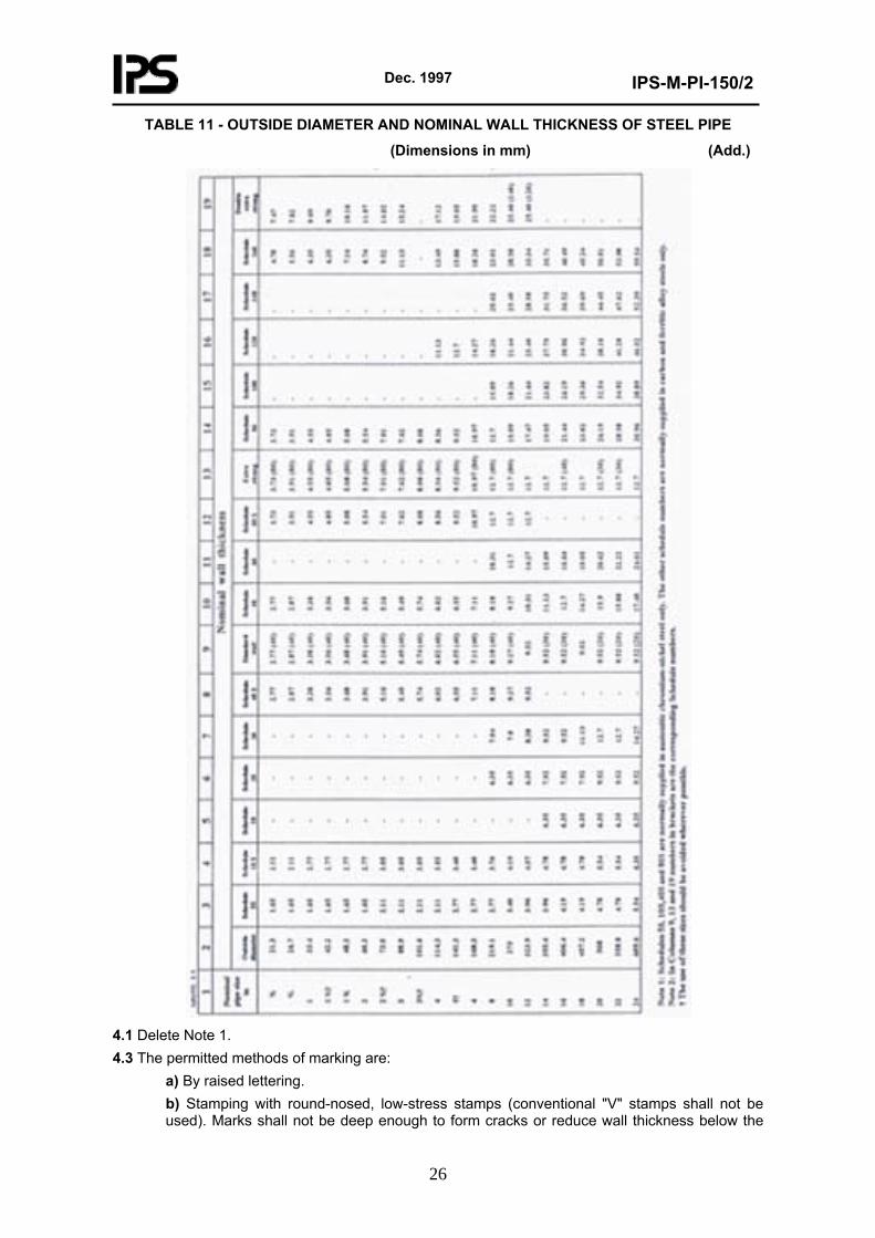
TABLE 11 - OUTSIDE DIAMETER AND NOMINAL WALL THICKNESS OF STEEL PIPE
(Dimensions in mm) (Add.)
4.1 Delete Note 1. 4.3 The permitted methods of marking are:
a) By raised lettering. b) Stamping with round-nosed, low-stress stamps (conventional "V" stamps shall not be used). Marks shall not be deep enough to form cracks or reduce wall thickness below the
Dec. 1997
IPS-M-PI-150/2
27
minimum required. c) Electro-etching or vibro-tool marking. (Add.)
4.4 Marking shall not be applied to internal surfaces, highly stressed parts and weld preparation surfaces. (Add.) 4.5 Marking by stamping shall be applied prior to heat treatment and stress relief. In this context, heat treatment includes postweld heat treatment and stress relief. (Add.) 4.6 Each component shall be marked with identification numbers or symbols which enable the cast or melt number and heat treatment to be traced. (Add.) 4.7 When color coding is specified for material identification, it may be based on BS 5383, but shall be subject to approval by the Engineer. (Add.) 5.1 Any particular requirements for materials used in low temperature services shall be specified by Engineer. (Add.) 5.2 The following limitations shall apply to all materials:
a) The carbon content by ladle analysis shall be 0.23% maximum for plate and 0.25% maximum for forgings. b) The manufacturer shall ensure on a basis of regular production checks that the carbon equivalent (CE) by ladle analysis does not exceed 0.45% where:
CE = C +6
Mn +
5 V Mo Cr ++
+15
Ni Cu +
Note: If necessary, in order to achieve minimum specified strengths, it shall be permissible to exceed the specified maximum manganese content, up to a maximum of 1.60%, provided the maximum permitted CE is not exceeded. Where the carbon content is limited, the actual tensile strength of the steel of any component should not exceed the min imum required by the relevant specification by more than 150 N/mm² (21, 750 psi) or 130 N/mm² (18, 850 psi) for steels with minimum tensile strength above 450 N/mm² (65, 260 psi).
c) Fittings made from longitudinally welded pipe shall have the weld and adjacent pipe radiographed after forming, in accordance with 5.2 of ASTM A 234-82 a. (Add.)
5.3 Materials to ASTM specifications shall additionally conform to the following as applicable: ASTM A 105, i) All forgings shall be normalised. A 106 and A181
ii) Forgings requiring weld repair are unacceptable. iii) Limitations (a) and (b) of clause 5.2 shall apply.
ASTM A 182 i) Forgings requiring weld repair are unacceptable. ii) Limitation (a) of clause 5.2 shall apply where appropriate.
ASTM A 234 i) Pipe used for manufacture of carbon steel fittings shall be seamless up to DN 400(NPS 16). For larger sizes, welded pipe may be used, the welding procedure being subject to approval by the Engineer. ii) Fittings requiring weld repairs are unacceptable. iii) Limitations (a), (b) and (c) of clause 5.2 shall apply.
ASTM A 350 i) Forgings requiring weld repair are unacceptable. ii) Limitations (a) and (b) of clause 5.2 shall apply only to carbon steels.
ASTM A 387 i) All flanges and flanged fittings shall be supplied in the normalised and tempered condition.
ASTM A 403 i) Forgings requiring weld repair are unacceptable.
Dec. 1997
IPS-M-PI-150/2
28
ASTM A 420 i) Chemical composition and mechanical properties shall conform to: Starting plate ASTM A 516, grade 60, 65 and 70 Starting plate ASTM A 333 grade 6 and ASTM A 334 grade 6
and tube ii) Pipe and tube used for the manufacture of fittings up to and including DN 400 (NPS 16) shall be seamless. Larger fittings may be made from fusion welded pipe. Welding and inspection procedures shall be subject to approval by the Engineer. iii) All welds (fabrication welds and welds in starting pipe) shall be subject to procedure qualification impact tests. iv) Forgings shall conform to ASTM A 350, grade LF2. v) For fully-killed aluminum-treated steels, impact testing of heat-affected zones of the parent metal is not required. (Add.)
12. INSPECTION (Add.) 12.1 When specified by the Purchaser, tests on materials or components shall be witnessed by the purchaser, or his appointed inspector. 12.2 The Purchaser or his appointed inspector shall be given access to those parts of the manufacturer’s works engaged on the production of fittings for Company, to inspect the materials being processed at any stage of manufacture. The Purchaser may reject any materials or components which in his opinion do not conform with this Standard. 13. CERTIFICATION (Add.) 13.1 The manufacturer shall submit certificates for chemical composition and physical properties together with details of any tests and heat treatments applied. 13.2 Certification may be waived only with the approval of the Purchaser. The marking shall then be taken as certification that the requirements of the purchase order and this Standard have been met. 14. DISPATCH (Add.) 14.1 Requirements for packaging and labeling shall be specified in the purchase order.
7. SECTION B: HIGH TEST WROUGHT BUTT WELDING FITTINGS FOR OFF-PLOT PIPING SYSTEMS
This section is supplement to reference standard MSS-SP-75(1988).
1.5 Additional requirements may be specified by Purchaser for sour services. (Add.)
1.6 This section shall not be applied to general refinery and petrochemical plant duties. (Add.)
2.5 Add to This Clause
The fitting shall be designed following the methodology described in ASME VIII Division 1 Appendix 2 or equivalent, using the design pressure, design temperature and design factor of the pipeline, and the anticipated external loads acting on the fitting.
6.5 The fittings should be designed in material with a strength equal to linepipe for which they are intended. Any reduction in strength shall be accompanied by an appropriate increase in thickness. (Add.)
Dec. 1997
IPS-M-PI-150/2
29
7.4 For sour service the limit on sulphur shall be reduced to 0.005% maximum and additional limitations on manganese may be necessary. (Add.)
7.5 The analysis shall be determined both on each heat of steel used, and on a broken mechanical test piece from each heat. (Add.)
7.6 Other elements shall not be added to the steel without approval of Purchaser. (Add.)
7.7 If any part of the product analysis fails to meet the requirements of 7.1, the whole heat shall be rejected or each individual item shall be fully analysed and all items failing to meet the requirements shall be rejected. (Add.)
8.9 The transverse tensile properties (yield strength, tensile strength, elongation and reduction of area) shall be determined in the parent metal and any weld using the round bar transverse specimen of API Specification 5L. The tensile properties shall meet the requirements for the equivalent line pipe and the transverse yield strength shall not exceed 600 Mpa. (Add.)
9.1 Substitute with Last Sentence
When the fitting consists of several components assembled together by welding, without further cold or hot forming, the individual components may be heat treated separately, i.e. prior to assembly.
9.1.1 Welds made to assemble individual components shall be post weld heat treated if the wall thickness exceeds 25 mm.
Fittings, or their individual components, shall be heat treated in accordance with Clause 9.1.2, 9.1.3 or 9.1.4. (Sub.)
10.5 The Inspector will only permit a retest if there is reason to believe that failure was due to some fault in preparationor testing, and that the result was not representative of the test sample. Otherwise the failed test shall be carried out on every fitting in the heat or lot, or alternatively the entire heat or lot shall be re-heat-treated and the full set of tests carried out on one item. (Sub.)
11.1 Add to the End of this Clause
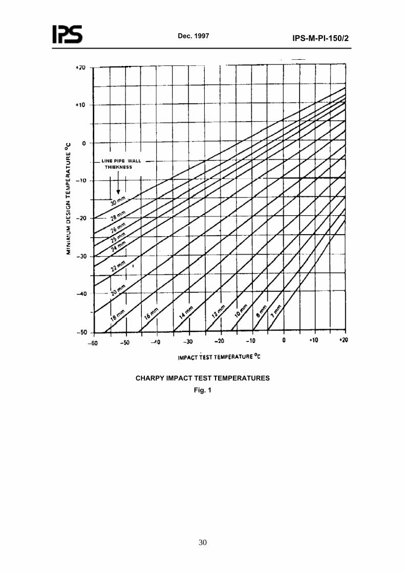
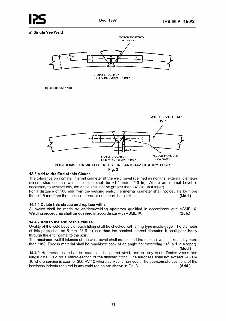
Transverse Charpy V-notch impact test pieces shall be taken from parent metal. In addition Charpy V-notch impact test pieces shall be taken from any longitudinal weld and HAZ, as shown in Fig. 2. The minimum acceptable Charpy toughness shall be an average, from three specimens, of 50J with no individual value below 40J. The test temperature shall be established from Fig. 1, using the wall thickness of the matching line pipe. The test temperature shall not be greater than the minimum design temperature.
Dec. 1997
IPS-M-PI-150/2
30
CHARPY IMPACT TEST TEMPERATURES
Fig. 1
Dec. 1997
IPS-M-PI-150/2
31
a) Single Vee Weld
POSITIONS FOR WELD CENTER LINE AND HAZ CHARPY TESTS
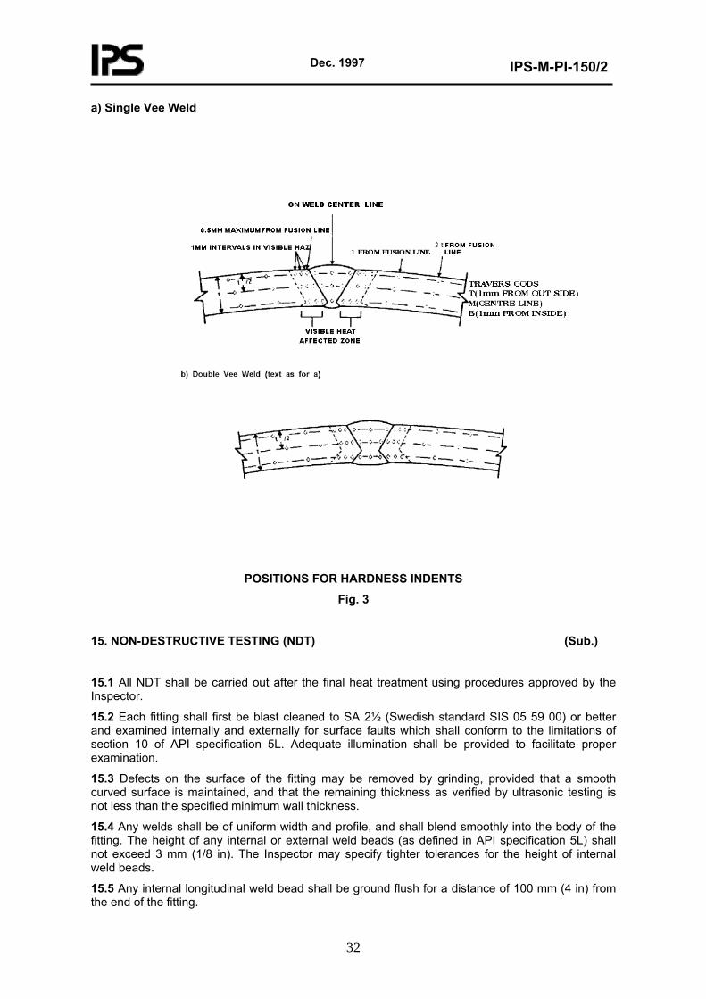
Fig. 2 13.3 Add to the End of this Clause The tolerance on nominal internal diameter at the weld bevel (defined as nominal external diameter minus twice nominal wall thickness) shall be ±1.5 mm (1/16 in). Where an internal bevel is necessary to achieve this, the angle shall not be greater than 14° (a 1 in 4 taper). For a distance of 100 mm from the welding ends, the internal diameter shall not deviate by more than ±1.5 mm from the nominal internal diameter of the pipeline. (Mod.) 14.4.1 Delete this clause and replace with: All welds shall be made by welders/welding operators qualified in accordance with ASME IX. Welding procedures shall be qualified in accordance with ASME IX. (Sub.) 14.4.2 Add to the end of this clause Ovality of the weld bevels of each fitting shall be checked with a ring type inside gage. The diameter of this gage shall be 5 mm (3/16 in) less than the nominal internal diameter. It shall pass freely through the end normal to the axis. The maximum wall thickness at the weld bevel shall not exceed the nominal wall thickness by more than 10%. Excess material shall be machined back at an angle not exceeding 14° (a 1 in 4 taper). (Mod.) 14.4.9 Hardness tests shall be made on the parent steel, and on any heat-affected zones and longitudinal weld on a macro-section of the finished fitting. The hardness shall not exceed 248 HV 10 where service is sour, or 300 HV 10 where service is non-sour. The approximate positions of the hardness indents required in any weld region are shown in Fig. 3. (Add.)
Dec. 1997
IPS-M-PI-150/2
32
a) Single Vee Weld
POSITIONS FOR HARDNESS INDENTS
Fig. 3
15. NON-DESTRUCTIVE TESTING (NDT) (Sub.)
15.1 All NDT shall be carried out after the final heat treatment using procedures approved by the Inspector.
15.2 Each fitting shall first be blast cleaned to SA 2½ (Swedish standard SIS 05 59 00) or better and examined internally and externally for surface faults which shall conform to the limitations of section 10 of API specification 5L. Adequate illumination shall be provided to facilitate proper examination.
15.3 Defects on the surface of the fitting may be removed by grinding, provided that a smooth curved surface is maintained, and that the remaining thickness as verified by ultrasonic testing is not less than the specified minimum wall thickness.
15.4 Any welds shall be of uniform width and profile, and shall blend smoothly into the body of the fitting. The height of any internal or external weld beads (as defined in API specification 5L) shall not exceed 3 mm (1/8 in). The Inspector may specify tighter tolerances for the height of internal weld beads.
15.5 Any internal longitudinal weld bead shall be ground flush for a distance of 100 mm (4 in) from the end of the fitting.
Dec. 1997
IPS-M-PI-150/2
33
15.6 Longitudinal, circumferential and repair welds shall be 100% radiographed. The radiographic examination shall be conducted with X-ray requirement using lead screens and films of agreed type. The image quality indicator shall be of agreed type and the thinnest wire clearly visible across the weld shall be not more than 1.25% of the wall thickness.
15.7 The following faults disclosed by radiography are unacceptable:
a) Cracks or incomplete penetration or fusion of any size.
b) Porosity exceeding 1% of the weld area in any 50 mm (2 in) length of weld.
c) Any slag inclusion exceeding 3 mm (1/8 in) long or 1.5 mm (1/16 in) wide.
d) Slag inclusions exceeding 6 mm (¼ in) total length in 100 mm (4 in) of weld.
15.8 Repairs to welded seams shall be limited to two per fitting, shall not exceed 5% of the seam length, and shall be carried out prior to final normalizing heat treatment.
15.9 Body repairs by welding shall not be permitted.
15.10 Cracks shall not be repaired and shall be cause for rejection. The cause of cracking shall be investigated, and established to the satisfaction of the Inspector.
15.11 Each fitting shall be examined for laminations, using an ultrasonic method approved by the Inspector covering a band at least 25 mm (1 in) wide at each end of the fitting.
15.12 Each fitting shall be dimensionally checked for the tolerance on diameter and out of roundness (see 21.1). The tolerance on wall thickness shall be checked at a minimum of 10 points equidistant around the circumference of the fitting.
15.13 After beveling, the whole surface of the bevel and 100 mm (4 in) at each end of any longitudinal weld shall be examined by wet magnetic particle inspection, to BS 6072. Defects such as laps, cracks or laminations shall not be permitted.
Laps and laminations less than 5 mm (3/16 in) deep shall be ground out and weld repaired to an approved procedure.
15.14 Hardness tests shall be performed externally at approximate 0.1 diameter intervals using a portable instrument approved by the Inspector e.g. equotip. Values shall not exceed those stated in 14.4.9.
16.1 The manufacturer shall provide Purchaser or his appointed Inspector with the followings:
a) Full access to all stages of the manufacturing process at all reasonable times.
b) Reasonable facilities for inspection.
c) To stamp or otherwise identify fittings and test pieces, and to reject any material which does not comply with the requirements of this Standard.
d) To witness all mechanical tests and see that agreed forming processes, heat treatments and non-destructive tests are employed, and that chemical analysis and finished dimensions of the product are within agreed tolerances.
e) To carry out dimensional checks on any fitting at any point to ensure that it conforms to the requirements of this Standard (see 21.1).
Note:
Inspection by Purchaser or his appointed Inspector does not relieve the manufacturer of his responsibility to ensure that the quality plan is strictly implemented and that related documentation is available.
(Sub. with first two sentences)
16.2 Add to This Clause:
An inspection certificate shall be provided by the manufacturer in accordance with the following:
Dec. 1997
IPS-M-PI-150/2
34
• ISO 10474 Type 5.1 B for chemical analysis, mechanical properties, notch toughness properties, hardness properties, heat treatment, non-destructive examination.
• ISO 10474 Type 5.1 C for other tests, e.g. dimensional checks, pressure test (when specified), functional checks. (Mod.)
17.1 Add to This Clause:
When sour service conditions are specified, the fitting shall be stamped "NACE MR 0175". (Mod.)
18. SUPPLEMENTARY REQUIREMENTS
SR-5
The base material and welds shall have a maximum hardness of 325 HV 10.
When sour service conditions are specified, the base material and welds shall have a maximum hardness as specified in NACE MR 0175.
Base metal hardness readings shall be made as per ASTM E 92 on each heat lot of fittings at 5 random locations.
As part of the welding procedure qualification tests, a hardness traverse shall be carried out across welds and heat affected zones at a distance of 2 mm from the external surface of the welds. Three hardness impressions shall be made in the weld while hardness impressions shall be made at 1 mm intervals in the heat affected zone, beginning at the fusion line. (Sub.)
SR-6 Add to this clause:
In addition, the actual yield to tensile strength ratio shall not exceed 0.85. (Mod.)
SR-7
The notch toughness properties shall be determined in accordance with section 11.1 of this Standard.
From each heat of steel, 3 transverse specimens shall be taken from the base material. As part of the welding procedure qualification tests, three sets of three transverse specimens shall be taken from welds at the following locations: weld center, fusion line, and fusion line +2 mm.
For flanged components in the fitting, the thickness used for determining the test temperature shall be either the thickness of the flange divided by 4 or the thickness at the weld preparation, whichever is greater. (Sub.)
SR-9 Add to this clause:
The welding ends of each fitting shall be 100% ultrasonically tested over a distance of 25 mm from each end from both the internal and external surfaces.
The acceptance criteria for ultrasonic inspection shall be in accordance with ASME VIII Division 1, Appendix 12. (Mod.)
SR-11
The carbon equivalent defined in 5.2(b) shall not exceed 0.43%. The carbon content shall not exceed 0.23% or 25% for forgings.
When sour service conditions are specified, the materials shall comply in addition with the requirements of NACE Standard MR 0175, and shall be proven to be resistant to hydrogen induced cracking. (Sub.)
19. CERTIFICATION (Add.)
19.1 The original steel makers and pipe makers certificates when applicable shall be supplied for
Dec. 1997
IPS-M-PI-150/2
35
each heat of steel used.
The Manufacturer shall prepare a test certificate for each heat of steel used (or each heat treatment lot where more than one lot is made from the same heat). This shall show the steel manufacturer, steelmaking process, heat number, heat analysis, product analysis, heat treatment, full mechanical properties as determined from test pieces for that heat or lot, and reference numbers of all fittings covered by the certificate. When bends manufactured by pressing and longitudinal welding are approved, full details of the welding consumables and weld metal properties shall be included. The certificate shall be subject to approval by the Purchaser.
20. INFORMATION REQUIRED WITH BID (Add.)
20.1 Any proposed deviations from this Standard.
20.2 The proposed chemical composition range.
20.3 The proposed guaranteed minimum mechanical properties.
20.4 If appropriate, the names of companies to whom similar fittings have previously been supplied should be given, together with the actual composition used and mechanical properties obtained.
20.5 Proposals for warranty in the event of failure of the fitting during field hydrostatic test.
20.6 The proposed manufacturing procedure and quality plan including steel making technique, casting technique, forming processes, heat treatments, welding procedure specifications where appropriate, non-destructive testing techniques and equipment, and the names of any sub-contractors involved, including steelmakers and pipemakers.
21. INFORMATION REQUIRED PRIOR TO MANUFACTURE (Add.)
21.1 Purchaser will specify whether the fitting will operate in sour on non-sour service.
21.2 The Manufacturer shall submit detailed shop drawings (including all nominal dimensions, wall thicknesses, tolerances, end bevel angles, grade of material and location of any weld seams) an his manufacturing procedure for approval by the Inspector before manufacture begins.
8. SECTION C: WROUGHT AND CAST STAINLESS STEEL BUTT WELDING FITTINGS
This section is supplement to reference standard MSS-SP-43 (1982).
3. SIZE
Size of the fittings in Table 1 through 7 and B.1 through B.7 and Annex A is identified by the corresponding nominal pipe size and wall thickness or schedule number of the pipe (see Table A.1) to which it is intended to correspond in strength. (Mod.)
4. MARKING
4.1
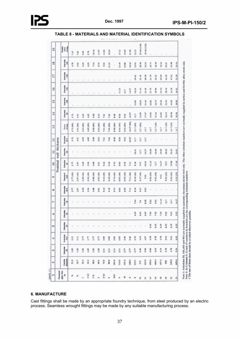
b) Material identification symbol (see Table 8). (Sub.)
e) Melt reference (for casting). (Add.)
Dec. 1997
IPS-M-PI-150/2
36
4.3 Add to the End of Clause
Fittings shall not be steel stamped, except that the melt reference may be steel stamped on cast fitting before final heat treatment; but such stamp marks shall be removed after the heat treatment by light grinding, and the reference replaced by other means.
5. MATERIAL
Fittings to this Standard shall be made of material complying with one of the standards given in Table 8. By agreement between Purchaser and Manufacturer other types of austenitic chromium-nickel steel may be used.
Carbon content of "L" grade stainless steel shall be limited to 0.03% max. Where Manufacturer offers materials exceeding o.030% max. carbon (see ASTM A 312 Table 1, Note B), procurement shall be subject to the approval of the Purchaser. (Sub.)
Dec. 1997
IPS-M-PI-150/2
37
TABLE 8 - MATERIALS AND MATERIAL IDENTIFICATION SYMBOLS
6. MANUFACTURE
Cast fittings shall be made by an appropriate foundry technique, from steel produced by an electric process. Seamless wrought fittings may be made by any suitable manufacturing process.
Dec. 1997
IPS-M-PI-150/2
38
Fitting fabricated by welding shall be made by an electric fusion-welding process, unless otherwise agreed between Purchaser and Manufacturer.
The qualification requirements for welders and welding operators, the welding procedure employed in the manufacture of fabricated fittings and welding materials shall be in accordance with ASME section IV latest edition. (Sub.)
6.1 Heat Treatment
Unless otherwise agreed between Purchaser and manufacturer, the fittings shall be heated uniformly to a temperature between 1000°C (1830°F) and 1150°C (2100°F) and then cooled rapidly in air or water. (Add.)
6.2 Descaling
All finished fittings shall be descaled by an appropriate process. (Add.)
6.3 Repair of Defects
Repairs to welded seams in fabricated fittings when approved, shall be effected by cleaning-out to sound metal and then re-welding. Repaired fittings shall be re-heat treated and re-tested in accordance with the requirements of 6.1, 8.3 and 8.5.
Repairs to cast fittings shall comply with Clause 14 of BS 1504 . Repaired fittings shall be re-heat treated and retested, in accordance with 8.3 and 8.5. (Add.)
7. FITTING DIMENSIONS
7.1 Inch dimensions for fittings covered by this Standard are given in Table 1 through 7. The metric dimensions are
given in Tables B.1 through B.7. (Mod.)
Dec. 1997
IPS-M-PI-150/2
39
TABLE 7 - DIMENSIONS OF 90° LONG RADIUS TANGENT ELBOWS 1 2 3
Nominal pipe size
Center to end A
Tangent T
in 1½ 2
2½ 3
3½ 4 5 6 8
10 12 14 16 18 20 24
in 2¼ 3
3¾ 4½ 5¼ 6
7½ 9
12 15 18 21 24 27 30 36
in 1¼ 1¼ 1¼ 1¼ 1½ 1½ 1½ 1¾ 2
2½ 3
3½ 4
4½ 5 6
Notes:
1) The tangent length T makes it possible to fit a slip-on welding flange to the elbow.
2) Tangent elbows having a tangent length at one end only are to be regarded as the standard type of fitting, but elbows having tangent lengths at both ends may be supplied when specified by the Purchaser. (Add.)
Dec. 1997
IPS-M-PI-150/2
40
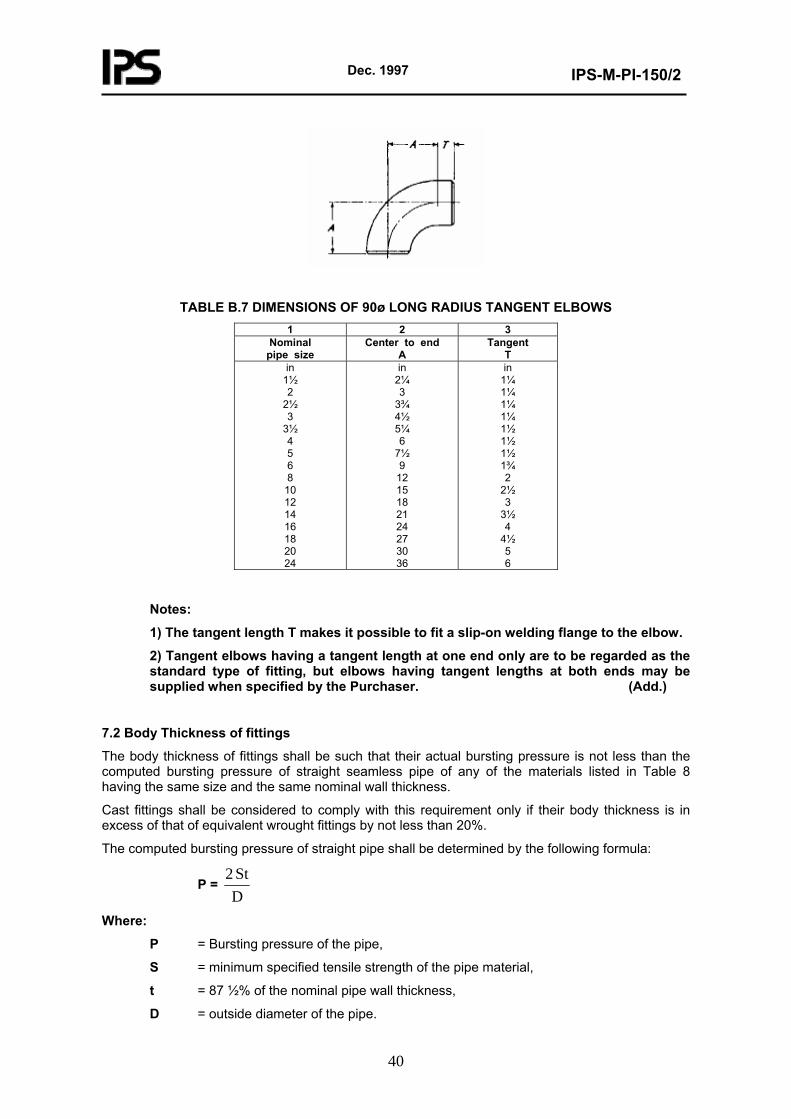
TABLE B.7 DIMENSIONS OF 90ø LONG RADIUS TANGENT ELBOWS 1 2 3
Nominal pipe size
Center to end A
Tangent T
in 1½ 2
2½ 3
3½ 4 5 6 8
10 12 14 16 18 20 24
in 2¼ 3
3¾ 4½ 5¼ 6
7½ 9
12 15 18 21 24 27 30 36
in 1¼ 1¼ 1¼ 1¼ 1½ 1½ 1½ 1¾ 2
2½ 3
3½ 4
4½ 5 6
Notes:
1) The tangent length T makes it possible to fit a slip-on welding flange to the elbow.
2) Tangent elbows having a tangent length at one end only are to be regarded as the standard type of fitting, but elbows having tangent lengths at both ends may be supplied when specified by the Purchaser. (Add.)
7.2 Body Thickness of fittings
The body thickness of fittings shall be such that their actual bursting pressure is not less than the computed bursting pressure of straight seamless pipe of any of the materials listed in Table 8 having the same size and the same nominal wall thickness.
Cast fittings shall be considered to comply with this requirement only if their body thickness is in excess of that of equivalent wrought fittings by not less than 20%.
The computed bursting pressure of straight pipe shall be determined by the following formula:
P = DSt 2
Where:
P = Bursting pressure of the pipe,
S = minimum specified tensile strength of the pipe material,
t = 87 ½% of the nominal pipe wall thickness,
D = outside diameter of the pipe.
Dec. 1997
IPS-M-PI-150/2
41
Note:
Coherent units should be used.
To ensure adequacy of design the manufacturer shall carry out bursting tests on prototype fittings. These bursting tests shall be made as specified in Clause 8.2. (Add.)
7.3 Dimensions of Welding Ends
The dimensions of the welding ends shall match those of the equivalent straight pipe dimensions, subject to the tolerances in clause 9. In order to obtain the proper dimensions at the welding ends, it is permissible to machine the inside of the fittings to a taper of not less than 1 in 4.
In the case of cast fittings the inside and outside surfaces at the ends shall be machine finished overall. The inside surfaces shall be machined parallel for a distance equal to 1½ times the corresponding nominal pipe wall thickness and then run out into the bore without abrupt change of section. The outside surface may be machined in any manner that avoids sharp angles and abrupt changes of slope in joining the bevel. (Add.)
8. TESTS (Sub.)
8.1 Test Facilities
Manufacturer shall prepare the necessary test pieces and supply the material required, the labour and appliances for such testing as may be carried out on his premises in accordance with this Standard. In the absence of facilities at his own works for making the prescribed tests, the Manufacturer shall arrange for the tests to be carried out elsewhere. (Add.)
8.2 Prototype Bursting Tests
These bursting tests shall be made in the following manner. Straight seamless pipe of any one of the materials listed in Table 8 (Section A), and of the same nominal wall thickness as the fitting to be tested and having a length equal to at least twice the pipe outside diameter shall be welded to each end of the fitting. Closures beyond the minimum length of the pipe shall be welded to the pipe ends.
Hydrostatic pressure shall be applied to the assembly and increased until either the fitting or one of the pipes bursts.
The prototype test on a fitting made of any one of the materials listed in Table 8 may be taken as representative of a fitting of the same size and nominal wall thickness of any of the other materials listed in Table 8.
The fitting shall be considered satisfactory if the pressure attained on bursting is equal to or greater than the computed bursting pressure of the straight pipe as ascertained by the formula in Clause 7.2.
If so specified by the Purchaser, the Manufacturer shall supply certificates stating that satisfactory bursting tests have been carried out on prototype fittings of the types and size covered by the Purchaser’s order. (Add.)
Dec. 1997
IPS-M-PI-150/2
42
8.3 Non-Destructive Testing (Add.)
8.3.1 Radiography
8.3.1.1 Cast fittings
Each fitting shall be subjected to complete radiographic examination to ensure freedom from harmful internal defects.The radiographic technique employed and the quality of films obtained thereby shall be generally in accordance with BS 2600 or BS 2910 as far as practicable and applicable. Acceptance limits shall be a matter for agreement between Purchaser and Manufacturer. (Add.)
8.3.1.2 Fabricated fittings
All welds in finished fabricated fittings shall be subject to radiographic examination over their full length. The radiographic technique employed, and the quality of the films obtained thereby, shall be as specified in BS 2600 or in BS 2910, whichever is applicable. The techniques 2, 7 or 11 quoted in these standards may be used. Acceptance limits shall be as specified in BS 3351, except that incomplete penetration shall not be permitted in longitudinal seams. (Add.)
8.3.2 Dye-penetrant method
The surface of all finished cast fittings, and the welded seams of all fabricated fitting shall be examined by the dyepenetrant or similar technique to ensure freedom from harmful surface flaws. Acceptance limits shall be a matter of agreement between Purchaser and Manufacturer. (Add.)
8.4 Intercrystalline Corrosion Test (Add.)
8.4.1 Wrought fittings
All materials listed in Table 8 (Section A) shall be subjected to the intercrystalline corrosion test specified in BS 1501 or BS 1503§. (Add.)
8.4.2 Cast fittings
All materials listed in Table 8 (Section B) shall be subjected to the intercrystalline corrosion test specified in BS 1504§. (Add.)
8.5 Hydrostatic Testing (Add.)
8.5.1 Hydrostatic testing of wrought seamless fittings is not required by this Standard.
8.5.2 Hydrostatic testing of wrought fabricated and cast seamless and fabricated fittings shall be applied.
Unless the value of the test pressure is otherwise agreed between Purchaser and Manufacturer it shall be determined by the following formula:
P = DSt 2
Where:
P = minimum test pressure,
Dec. 1997
IPS-M-PI-150/2
43
S = 75% of the minimum specified yield stress of the material of which the fitting is made,
t = nominal wall thickness of the fitting,
D = outside diameter of the fitting at the bevel.
Note:
Coherent units should be used.
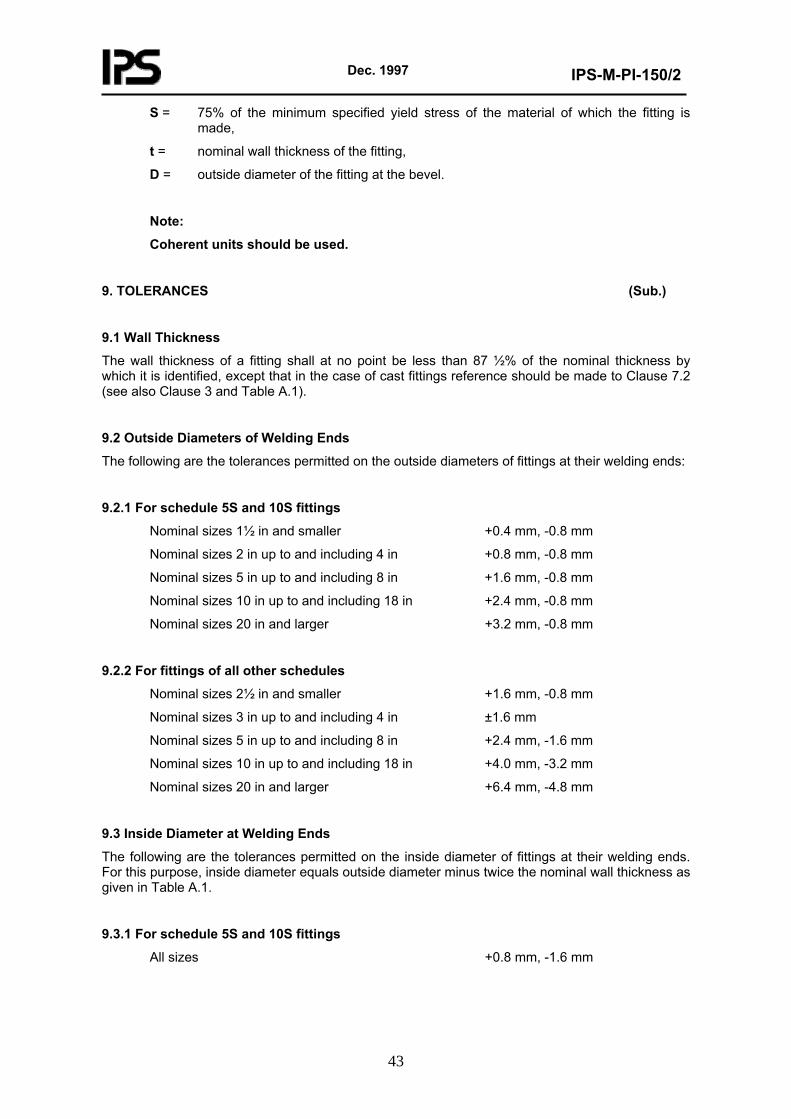
9. TOLERANCES (Sub.)
9.1 Wall Thickness
The wall thickness of a fitting shall at no point be less than 87 ½% of the nominal thickness by which it is identified, except that in the case of cast fittings reference should be made to Clause 7.2 (see also Clause 3 and Table A.1).
9.2 Outside Diameters of Welding Ends
The following are the tolerances permitted on the outside diameters of fittings at their welding ends:
9.2.1 For schedule 5S and 10S fittings
Nominal sizes 1½ in and smaller +0.4 mm, -0.8 mm
Nominal sizes 2 in up to and including 4 in +0.8 mm, -0.8 mm
Nominal sizes 5 in up to and including 8 in +1.6 mm, -0.8 mm
Nominal sizes 10 in up to and including 18 in +2.4 mm, -0.8 mm
Nominal sizes 20 in and larger +3.2 mm, -0.8 mm
9.2.2 For fittings of all other schedules
Nominal sizes 2½ in and smaller +1.6 mm, -0.8 mm
Nominal sizes 3 in up to and including 4 in ±1.6 mm
Nominal sizes 5 in up to and including 8 in +2.4 mm, -1.6 mm
Nominal sizes 10 in up to and including 18 in +4.0 mm, -3.2 mm
Nominal sizes 20 in and larger +6.4 mm, -4.8 mm
9.3 Inside Diameter at Welding Ends
The following are the tolerances permitted on the inside diameter of fittings at their welding ends. For this purpose, inside diameter equals outside diameter minus twice the nominal wall thickness as given in Table A.1.
9.3.1 For schedule 5S and 10S fittings
All sizes +0.8 mm, -1.6 mm
Dec. 1997
IPS-M-PI-150/2
44
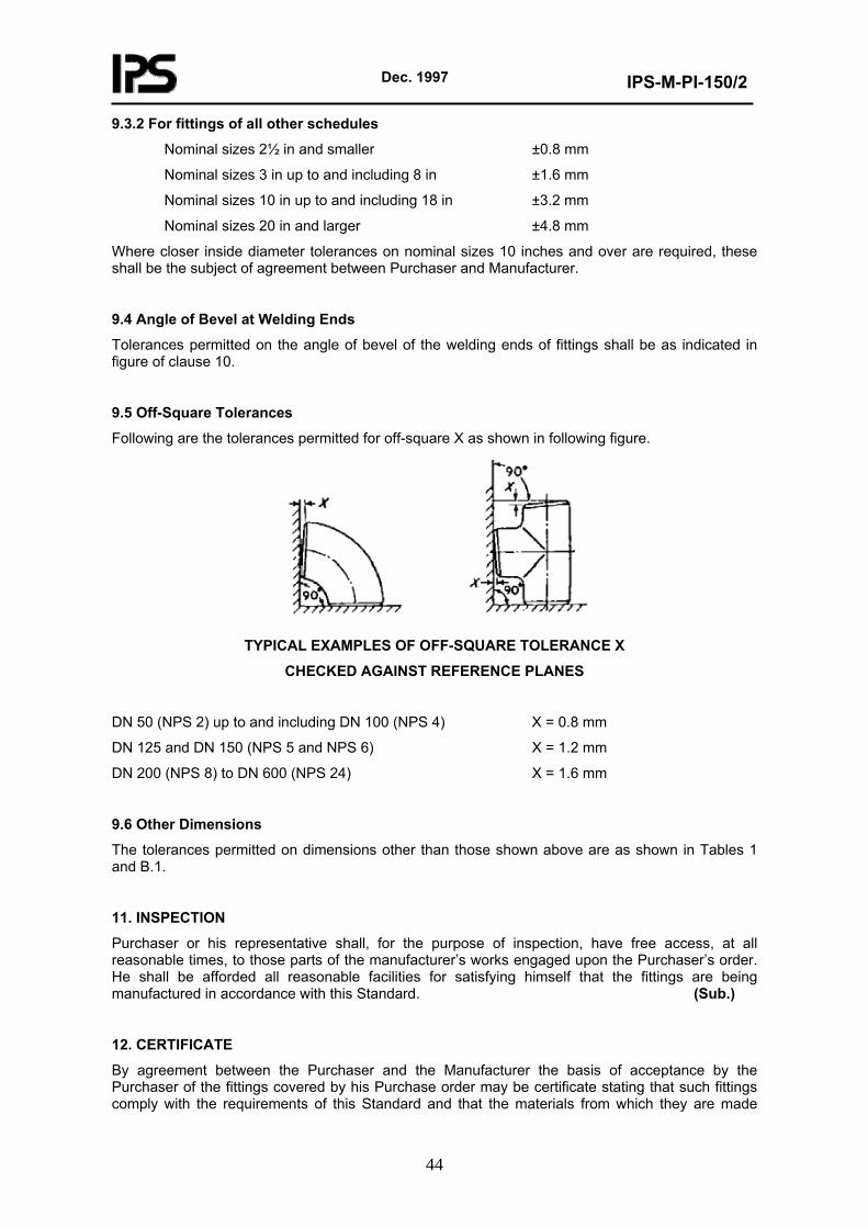
9.3.2 For fittings of all other schedules
Nominal sizes 2½ in and smaller ±0.8 mm
Nominal sizes 3 in up to and including 8 in ±1.6 mm
Nominal sizes 10 in up to and including 18 in ±3.2 mm
Nominal sizes 20 in and larger ±4.8 mm
Where closer inside diameter tolerances on nominal sizes 10 inches and over are required, these shall be the subject of agreement between Purchaser and Manufacturer.
9.4 Angle of Bevel at Welding Ends
Tolerances permitted on the angle of bevel of the welding ends of fittings shall be as indicated in figure of clause 10.
9.5 Off-Square Tolerances
Following are the tolerances permitted for off-square X as shown in following figure.
TYPICAL EXAMPLES OF OFF-SQUARE TOLERANCE X
CHECKED AGAINST REFERENCE PLANES
DN 50 (NPS 2) up to and including DN 100 (NPS 4) X = 0.8 mm
DN 125 and DN 150 (NPS 5 and NPS 6) X = 1.2 mm
DN 200 (NPS 8) to DN 600 (NPS 24) X = 1.6 mm
9.6 Other Dimensions
The tolerances permitted on dimensions other than those shown above are as shown in Tables 1 and B.1.
11. INSPECTION
Purchaser or his representative shall, for the purpose of inspection, have free access, at all reasonable times, to those parts of the manufacturer’s works engaged upon the Purchaser’s order. He shall be afforded all reasonable facilities for satisfying himself that the fittings are being manufactured in accordance with this Standard. (Sub.)
12. CERTIFICATE
By agreement between the Purchaser and the Manufacturer the basis of acceptance by the Purchaser of the fittings covered by his Purchase order may be certificate stating that such fittings comply with the requirements of this Standard and that the materials from which they are made
Dec. 1997
IPS-M-PI-150/2
45
have the chemical and physical characteristics specified in the appropriate standard or standards in Table 8. (Add.)
9. SECTION D: WROUGHT STEEL BUTT WELDING SHORT RADIUS ELBOWS AND RETURNS
Design, sizing manufacturing and test of these fittings shall be according to ASME/ANSI B 16.28 latest edition.
10. SECTION E: CARBON STEEL AND ALLOY STEEL THREADED AND SOCKET WELDING FITTINGS
This Section is supplement to reference standard ASME/ANSI B 16.11 (1980).
1. SCOPE
1.1 Change the number of tables from 4 through 7 to 4 through 10. (Mod.)
1.3 Change the number of tables from 4 through 7 and A4 through A7 to 4 through 10 and A4 through A10. (Mod.)
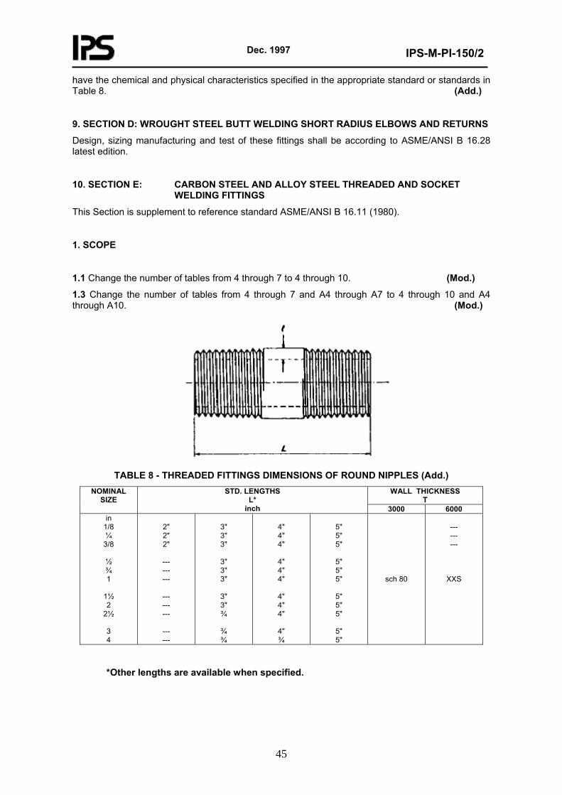
TABLE 8 - THREADED FITTINGS DIMENSIONS OF ROUND NIPPLES (Add.)
WALL THICKNESS T
NOMINAL SIZE
STD. LENGTHS L*
inch 3000 6000 in
1/8 ¼
3/8
½ ¾ 1
1½ 2
2½
3 4
2" 2" 2"
--- --- ---
--- --- ---
--- ---
3" 3" 3"
3" 3" 3"
3" 3" ¾
¾ ¾
4" 4" 4"
4" 4" 4"
4" 4" 4"
4" ¾
5" 5" 5"
5" 5" 5"
5" 5" 5"
5" 5"
sch 80
--- --- ---
XXS
*Other lengths are available when specified.
Dec. 1997
IPS-M-PI-150/2
46
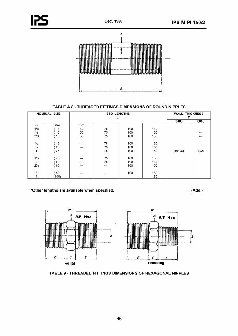
TABLE A.8 - THREADED FITTINGS DIMENSIONS OF ROUND NIPPLES WALL THICKNESS
T NOMINAL SIZE STD. LENGTHS
L* 3000 6000
in 1/8 ¼
3/8
½ ¾ 1
1½ 2
2½
3 4
Mm ( 6) ( 8) ( 10)
( 15) ( 20) ( 25)
( 40) ( 50) ( 65)
( 80) (100)
mm 50 50 50
--- --- ---
--- --- ---
--- ---
75 75 75
75 75 75
75 75 ---
--- ---
100 100 100
100 100 100
100 100 100
100 ---
150 150 150
150 150 150
150 150 150
150 150
sch 80
--- --- ---
XXS
*Other lengths are available when specified. (Add.)
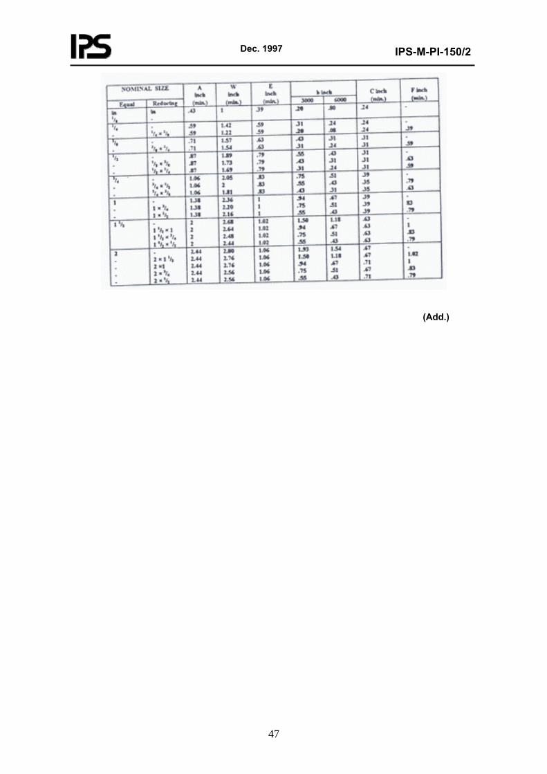
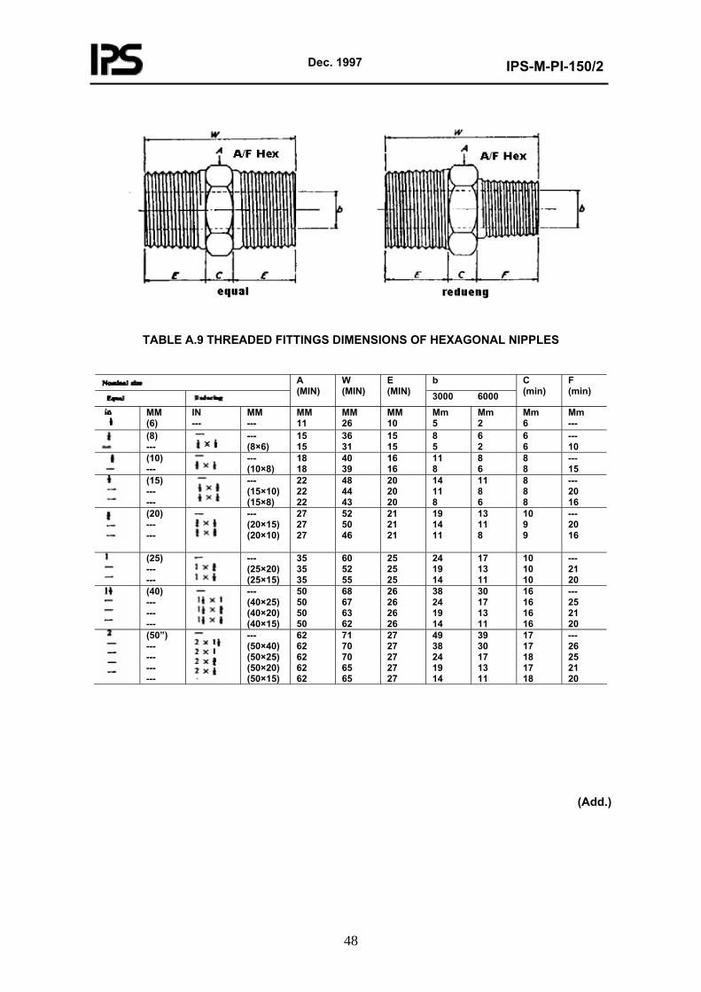
TABLE 9 - THREADED FITTINGS DIMENSIONS OF HEXAGONAL NIPPLES
Dec. 1997
IPS-M-PI-150/2
47
(Add.)
Dec. 1997
IPS-M-PI-150/2
48
TABLE A.9 THREADED FITTINGS DIMENSIONS OF HEXAGONAL NIPPLES
b
A (MIN)
W (MIN)
E (MIN) 3000 6000
C (min)
F (min)
MM (6)
IN ---
MM ---
MM 11
MM 26
MM 10
Mm 5
Mm 2
Mm 6
Mm ---
(8) ---
--- (8×6)
15 15
36 31
15 15
8 5
6 2
6 6
--- 10
(10) ---
--- (10×8)
18 18
40 39
16 16
11 8
8 6
8 8
--- 15
(15) --- ---
--- (15×10) (15×8)
22 22 22
48 44 43
20 20 20
14 11 8
11 8 6
8 8 8
--- 20 16
(20) --- ---
--- (20×15) (20×10)
27 27 27
52 50 46
21 21 21
19 14 11
13 11 8
10 9 9
--- 20 16
(25) --- ---
--- (25×20) (25×15)
35 35 35
60 52 55
25 25 25
24 19 14
17 13 11
10 10 10
--- 21 20
(40) --- --- ---
--- (40×25) (40×20) (40×15)
50 50 50 50
68 67 63 62
26 26 26 26
38 24 19 14
30 17 13 11
16 16 16 16
--- 25 21 20
(50”) --- --- --- ---
--- (50×40) (50×25) (50×20) (50×15)
62 62 62 62 62
71 70 70 65 65
27 27 27 27 27
49 38 24 19 14
39 30 17 13 11
17 17 18 17 18
--- 26 25 21 20
(Add.)
Dec. 1997
IPS-M-PI-150/2
49
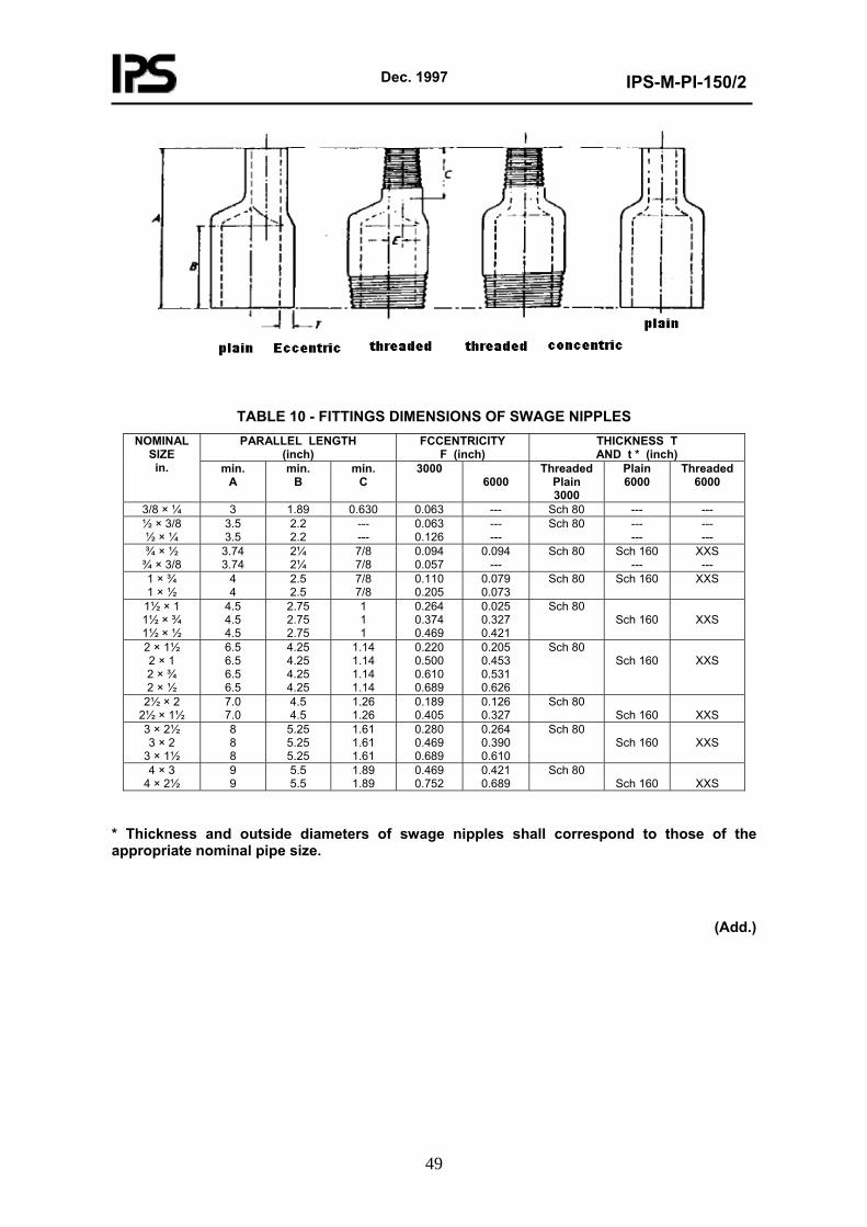
TABLE 10 - FITTINGS DIMENSIONS OF SWAGE NIPPLES PARALLEL LENGTH
(inch) FCCENTRICITY
F (inch) THICKNESS T AND t * (inch)
NOMINAL SIZE in. min.
A min.
B min.
C 3000
6000 Threaded
Plain 3000
Plain 6000
Threaded 6000
3/8 × ¼ 3 1.89 0.630 0.063 --- Sch 80 --- --- ½ × 3/8 ½ × ¼
3.5 3.5
2.2 2.2
--- ---
0.063 0.126
--- ---
Sch 80 --- ---
--- ---
¾ × ½ ¾ × 3/8
3.74 3.74
2¼ 2¼
7/8 7/8
0.094 0.057
0.094 ---
Sch 80 Sch 160 ---
XXS ---
1 × ¾ 1 × ½
4 4
2.5 2.5
7/8 7/8
0.110 0.205
0.079 0.073
Sch 80 Sch 160 XXS
1½ × 1 1½ × ¾ 1½ × ½
4.5 4.5 4.5
2.75 2.75 2.75
1 1 1
0.264 0.374 0.469
0.025 0.327 0.421
Sch 80 Sch 160
XXS
2 × 1½ 2 × 1 2 × ¾ 2 × ½
6.5 6.5 6.5 6.5
4.25 4.25 4.25 4.25
1.14 1.14 1.14 1.14
0.220 0.500 0.610 0.689
0.205 0.453 0.531 0.626
Sch 80 Sch 160
XXS
2½ × 2 2½ × 1½
7.0 7.0
4.5 4.5
1.26 1.26
0.189 0.405
0.126 0.327
Sch 80 Sch 160
XXS
3 × 2½ 3 × 2
3 × 1½
8 8 8
5.25 5.25 5.25
1.61 1.61 1.61
0.280 0.469 0.689
0.264 0.390 0.610
Sch 80 Sch 160
XXS
4 × 3 4 × 2½
9 9
5.5 5.5
1.89 1.89
0.469 0.752
0.421 0.689
Sch 80 Sch 160
XXS
* Thickness and outside diameters of swage nipples shall correspond to those of the appropriate nominal pipe size.
(Add.)
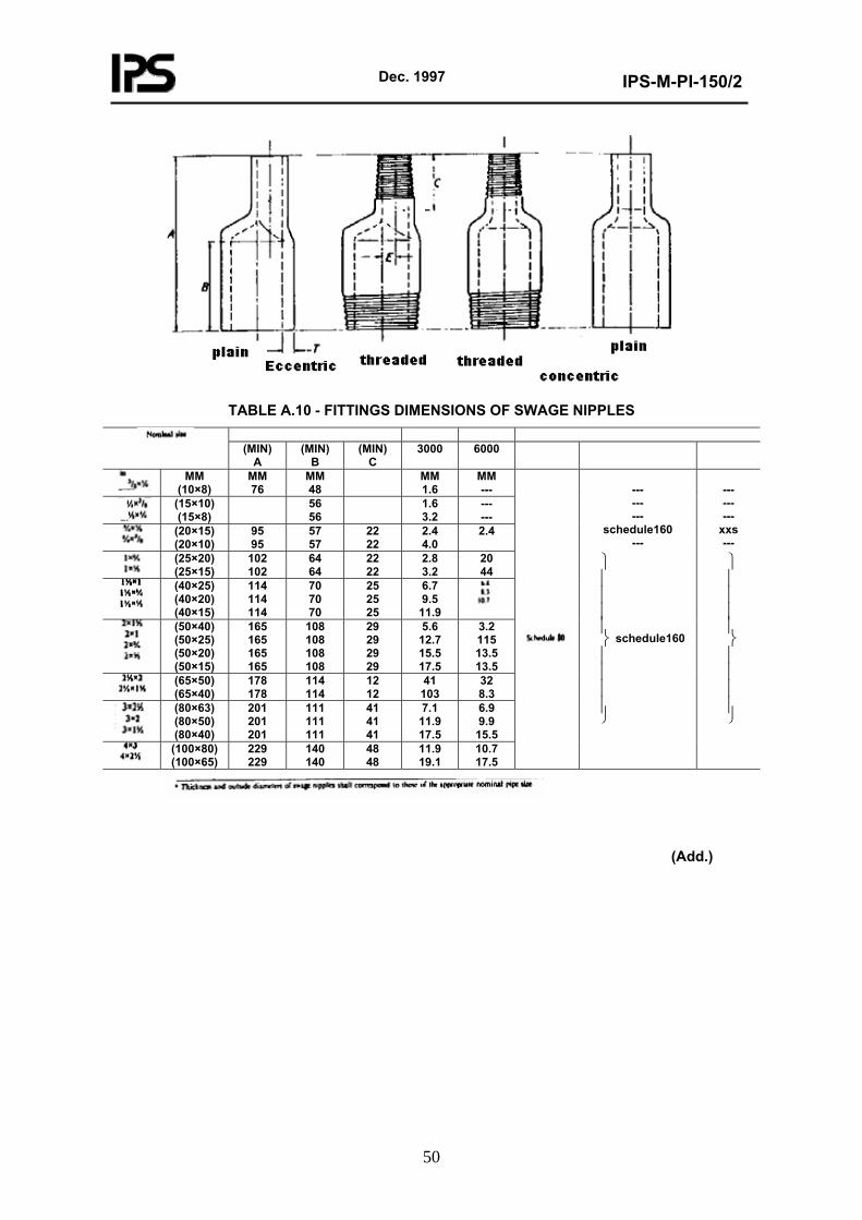
Dec. 1997
IPS-M-PI-150/2
50
TABLE A.10 - FITTINGS DIMENSIONS OF SWAGE NIPPLES
(MIN)
A (MIN)
B (MIN)
C 3000 6000
MM
(10×8) MM 76
MM 48
MM 1.6
MM ---
(15×10) (15×8)
56 56
1.6 3.2
--- ---
(20×15) (20×10)
95 95
57 57
22 22
2.4 4.0
2.4
(25×20) (25×15)
102 102
64 64
22 22
2.8 3.2
20 44
(40×25) (40×20) (40×15)
114 114 114
70 70 70
25 25 25
6.7 9.5
11.9
(50×40) (50×25) (50×20) (50×15)
165 165 165 165
108 108 108 108
29 29 29 29
5.6 12.7 15.5 17.5
3.2 115 13.5 13.5
(65×50) (65×40)
178 178
114 114
12 12
41 103
32 8.3
(80×63) (80×50) (80×40)
201 201 201
111 111 111
41 41 41
7.1 11.9 17.5
6.9 9.9
15.5
(100×80) (100×65)
229 229
140 140
48 48
11.9 19.1
10.7 17.5
--- --- ---
schedule160 ---
⎪⎪⎪⎪
⎭
⎪⎪⎪⎪
⎬
⎫
schedule160
--- --- ---
xxs ---
⎪⎪⎪⎪
⎭
⎪⎪⎪⎪
⎬
⎫
(Add.)
Dec. 1997
IPS-M-PI-150/2
51
TABLE 1 - TYPES OF FITTINGS BY CLASS AND SIZE RANGE
SOCKET-WELD THREADED DESCRIPTION
3000 6000 9000 2000 3000 6000 45° & 90° elbows 1/8 to 4 1/8 to 2 ½ to 2 1/8 to 4 1/8 to 4 1/8 to 4 Tees & crosses 1/8 to 4 1/8 to 2 ½ to 2 1/8 to 4 1/8 to 4 1/8 to 4 Coupling & half-coupling
1/8 to 4 1/8 to 2 ½ to 2 --- 1/8 to 4 1/8 to 4
CAP 1/8 to 3 ½ to 3 --- --- 1/8 to 4 1/8 to 4 Hexagonal nipples
--- --- --- --- 1/8 to 2 1/8 to 2
Round nipples --- --- --- --- 1/8 to 4 1/8 to 4 Swage nipples --- --- --- --- 3/8 × ¼ to 4 × 2½ Square & hex. & round plugs
--- 1/8 to 4 1)
Hex. & flush bushing
--- 1/8 to 4 1)
1) Plugs & bushing are not identified by pressure class. They maybe used for ratings up through pressure class 6000.
(Sub.)
2.3 Pressure/Temperature Ratings
Pressure/temperature rating are listed in Table 11.
Solid plugs and bushing do not carry specific ratings and are intended for use with threaded fittings of any of designation shown in Clause 2.1. (Add.)
4. Marking
4.1 Method of Marking
The method of marking used shall not be harmful to the fittings.
Hard stamping is permissible only by roller stamping. Stamping shall be done lightly and carefully so as to minimize the notch effect and not so deep as to cause cracks or reduce the wall thickness of fittings below the minimum allowed.
Stamping shall be applied prior to any final heat treatment when appropriate. (Sub.)
5. MATERIALS AND MANUFACTURE
5.1 Fittings may be produced by any of the following recognized processes:
1) Forging: elbows, crosses, tees.
2) Forging or machining from bar stock: caps, bushings, hexagonal nipples, pipe plugs.
3) Forging, or machining from bar stock or seamless pipe: couplings, half-couplings, round and swage nipples.
This Standard does not cover fittings which have been fabricated by welding.
Fittings to this Standard shall be made of materials complying with one of the standards listed in Table 12. (Sub.)
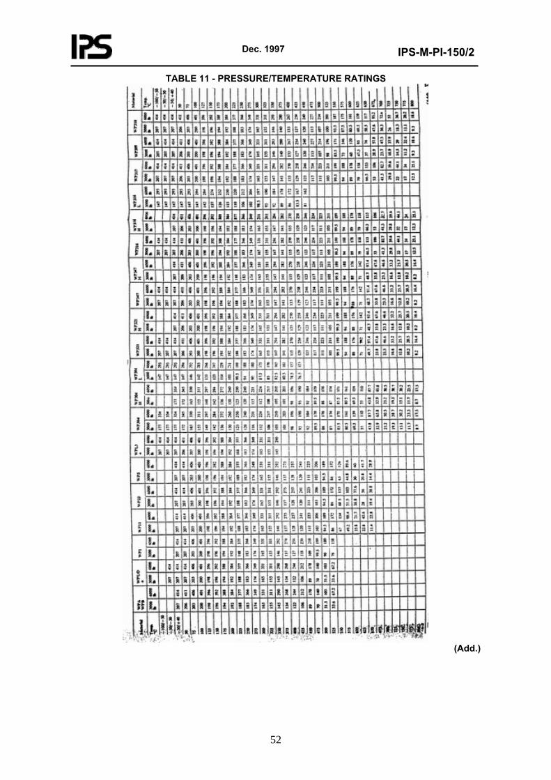
Dec. 1997
IPS-M-PI-150/2
52
TABLE 11 - PRESSURE/TEMPERATURE RATINGS
(Add.)
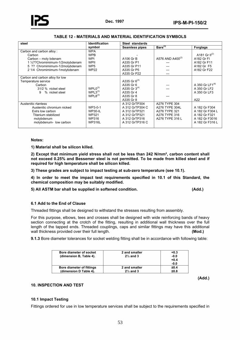
Dec. 1997
IPS-M-PI-150/2
53
TABLE 12 - MATERIALS AND MATERIAL IDENTIFICATION SYMBOLS Steel standards steel Identification
symbol Seamless pipes Bars(3) Forglags Carbon and carbon alloy : Carbon Carbon – moly bdenam 1 ½??Chromimimum-1/2molybdenam 5 ?? Chromimimum-1/2molybdenam 2 1/4 Chromimimum-1molybdenam
WPA WPB WPI WPII WP5 WP22
-
A106 Gr B A335 Gr P1 A335 Gr P11 A335 Gr P5 A335 Gr P22
A576 AND A400(2)
--- --- --- ---
A181 Gr II(2)
A182 Gr FI A182 Gr F11 A182 Gr F5 A182 Gr F22
Carbon and carbon alloy for low Temperature service Carbon 31/2 % nickel steel 9 % nickel steel
WPL0(3)
WPL3(3)
WPL8(3)
A335 Gr 6(4)
A335 Gr 6
A335 Gr 3(4)
A335 Gr 4
A335 Gr 8
A335 Gr 8
--- --- ---
A 350 Gr LF1(6)
A 350 Gr LF2 A 350 Gr LF3 A22
Austenitic rtantess Austenitic chromium nicked Exlrs low carbon Titanium stabilized molybdenum molybdenum- low carbon
WP3-0-1 WP30-IL WP321 WP316 WP316L
A 312 GrTP304 A 312 GrTP304 C A 312 GrTP321 A 312 GrTP321 A 312 GrTP316 A 312 GrTP316 C
A276 TYPE 304 A276 TYPE 304L A276 TYPE 321 A276 TYPE 316 A276 TYPE 316 L
A 182 Gr F304 A 182 Gr F304 L A 182 Gr F321 A 182 Gr F3016 A 182 Gr F316 L
Notes:
1) Material shall be silicon killed.
2) Except that minimum yield stress shall not be less than 242 N/mm², carbon content shall not exceed 0.25% and Bessemer steel is not permitted. To be made from killed steel and if required for high temperature shall be silicon killed.
3) These grades are subject to impact testing at sub-zero temperature (see 10.1).
4) In order to meet the impact test requirements specified in 10.1 of this Standard, the chemical composition may be suitably modified.
5) All ASTM bar shall be supplied in softened condition. (Add.)
6.1 Add to the End of Clause
Threaded fittings shall be designed to withstand the stresses resulting from assembly.
For this purpose, elbows, tees and crosses shall be designed with wide reinforcing bands of heavy section connecting at the crotch of the fitting, resulting in additional wall thickness over the full length of the tapped ends. Threaded couplings, caps and similar fittings may have this additional wall thickness provided over their full length. (Mod.)
9.1.3 Bore diameter tolerances for socket welding fitting shall be in accordance with following table:
Bore diameter of socket (dimension B, Table 4).
2 and smaller 2½ and 3
+0.3 -0.0 +0.4 -0.0
Bore diameter of fittings (dimension D Table 4).
2 and smaller 2½ and 3
±0.4 ±0.8
(Add.)
10. INSPECTION AND TEST
10.1 Impact Testing
Fittings ordered for use in low temperature services shall be subject to the requirements specified in
Dec. 1997
IPS-M-PI-150/2
54
the relevant material specification and in accordance with the requirements of BS 131: Part 2 and if so specified by the Purchaser. (Add.)
10.2 Hydrostatic Testing
Hydrostatic testing of fittings other than unions is not required by this Standard, but all fittings shall be capable of withstanding a hydrostatic test pressure of 1.5 times their designated pressure rating. (see clause 2). This test shall be applied only when specified in the Purchaser’s order. (Add.)
10.3 Inspection
The Purchaser or his representative shall, for the purpose of inspection, have free access at all reasonable times to those parts of the Manufacturer’s works engaged on the Purchaser’s order. He shall be afforded all reasonable facilities for satisfying himself that the fittings are being manufactured in accordance with this Standard. (Add.)
10.4 Test Facilities
Manufacturer shall prepare the necessary test pieces and supply the material required, the labour and appliances for such testing as may be carried out on his premises in accordance with this Standard. In the absence of facilities at his own works for making the prescribed tests, the Manufacturer shall arrange for the tests to be carried out elsewhere.
(Add.)
10.5 Workmanship and Finish
Fittings complying with this Standard shall be free from harmful defects and shall have a workmanlike finish.
Socket-welding fittings shall be faced at the ends at right angles to the axes.
The seats of unions shall be effectively protected against rust, during transit and storage. (Add.)
11. CERTIFICATION
By agreement between the Purchaser and the Manufacturer, the basis of acceptance by the Purchaser of the fittings covered by his order may be a certificate stating that such fittings comply with the requirements of this Standard, and that the material from which they are made has the chemical and physical characteristics specified in the appropriate standards listed in Table 12. (Add.)
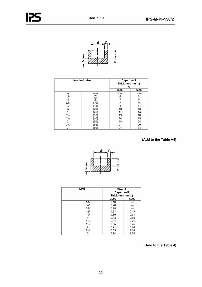
Dec. 1997
IPS-M-PI-150/2
55
Caps; wall Thickness (min.)
A
Nominal size
3000 6000 in
1/8 ¼
3/8 ½ ¾ 1
1¼ 1½ 2
2½ 3
mm (6) (8)
(10) (15) (20) (25) (32) (40) (50) (65) (80)
mm 4 7 7 8
10 11 13 14 18 21 24
mm ¾ ¾ ¾ 11 13 14 18 19 24 29 34
(Add to the Table A4)
Size A Caps: wall
Thickness (min.)
NPS
3000 6000 1/8² ¼²
3/8² ½² ¾² 1²
1¼² 1½² 2²
2½² 3²
0.16 0.28 0.28 0.31 0.39 0.43 0.51 0.55 0.71 0.83 0.94
--- --- ---
0.43 0.51 0.55 0.71 0.75 0.94 1.14 1.34
(Add to the Table 4)
Dec. 1997
IPS-M-PI-150/2
56
11. SECTION F: WELDING OUTLET FITTINGS 11.1 General Welding outlet fittings shall meet the general requirements of Clause 6 (butt-welding fittings) or Clause 10 (threaded socket-welding fittings) of this Part of the Standard. This Section of standard provides generally for the following types of forged steel outlet fittings:
- Weldolet, - Nipolet, - Sweepolet, - Latrolet & elbolet, - Thredolet, - Sockolet, - Coupolet.
Other types of fittings may be used subject to approval by the Purchaser. Manufacturer shall satisfy the Inspector that the design has been proven by means of burst or proof and fatigue tests and that the fittings have been designed to minimize stress concentrations. If specified by the Engineer sample/prototype forging shall be sectioned and etched to show flow lines. The test procedure and criteria of acceptable metal flow shall be subject to approval by the Inspector. 11.2 Temperature-Pressure Ratings Temperature-pressure rating of outlet fittings shall be the same as rating of header pipes which they should be branched. 11.3 Material Outlet fitting shall be made from materials listed in Table 11.1. 11.3.1 All fittings shall be forged. Welded, cast or fittings made from bar stock or machined from solid forged blocks are unacceptable. For sizes DN 50 (NPS 2) and below, forgings with solid bores machined out to suit pipe may be used. 11.3.2 Unless specified otherwise by the Purchaser austenitic stainless steel fittings shall be furnished in the solution annealed condition. No subsequent cold working is permitted. 11.4 Size and Dimensions 11.4.1 Butt-welding fittings shall be ordered by the schedule of mating pipe line and branch size, e.g. 8 in schedule 80 × 4 in schedule 80. 11.4.2 Socket-welding and threaded fittings shall be ordered by the pressure classification of 3000 lbs and 6000 lbs to meet the requirements of clause 10 of this Part of the Standard. 11.4.3 Table 11.2 outlines the full range of weldolet, thredolet, sockolet and nipolet size consolidation. All fittings shall be manufactured and marked as shown in this Table. All outlet sizes not listed in the table should be ordered to specific run pipe size. 11.4.4 Dimensions of different types of weldolets shall be in accordance with Tables 11.3 to 11.9 and for nippolets Table 11.10. 11.4.5 Tables 11.11 and 11.16 show different dimensions of Elbolets, latrolets, thredolets, sockolets, and coupolets.
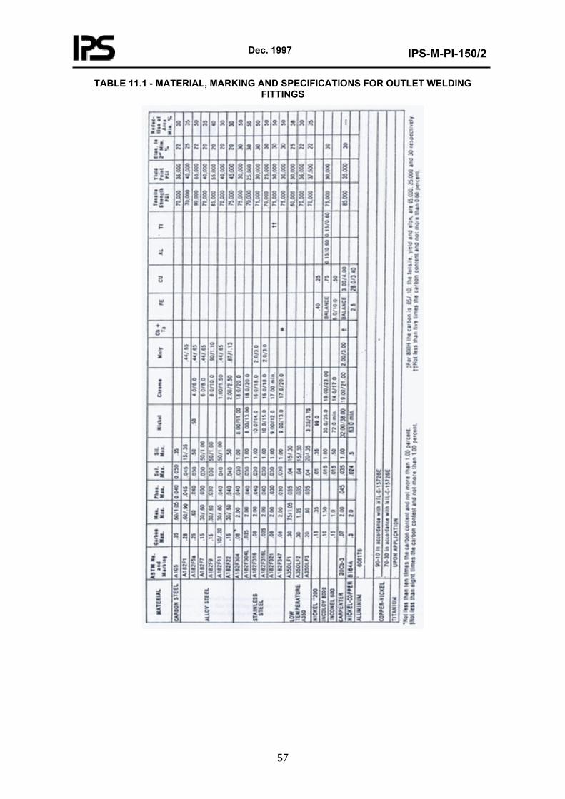
Dec. 1997
IPS-M-PI-150/2
57
TABLE 11.1 - MATERIAL, MARKING AND SPECIFICATIONS FOR OUTLET WELDING FITTINGS
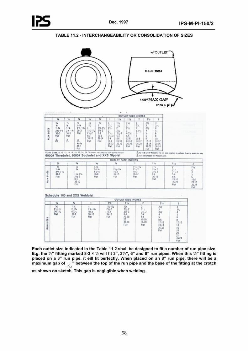
Dec. 1997
IPS-M-PI-150/2
58
TABLE 11.2 - INTERCHANGEABILITY OR CONSOLIDATION OF SIZES
Each outlet size indicated in the Table 11.2 shall be designed to fit a number of run pipe size. E.g. the ½” fitting marked 8-3 × ½ will fit 3”, 3½”, 6” and 8” run pipes. When this ½” fitting is placed on a 3” run pipe, it eill fit perfectly. When placed on an 8” run pipe, there will be a maximum gap of
321 ” between the top of the run pipe and the base of the fitting at the crotch
as shown on sketch. This gap is negligible when welding.
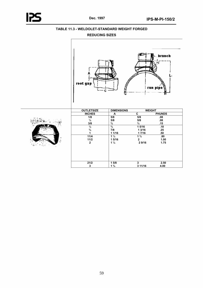
Dec. 1997
IPS-M-PI-150/2
59
TABLE 11.3 - WELDOLET-STANDARD WEIGHT FORGED
REDUCING SIZES
OUTLETSIZE DIMENSIONS WEIGHT INCHES A C PHUNDS
1/8 ¼
3/8
5/8 5/8 .08 5/8 5/8 .08 ¾ ¾ .15
½ ¾ 1
¾ 1 5/16 .18 7/8 1 3/16 .25 1 1/16 1 7/16 .50
11/4 11/2
2
1 ¼ 1 ¾ .80 1 5/16 2 1.00 1 ½ 2 9/16 1.75
21/2 3
1 5/8 3 2.50 1 ¾ 3 11/16 4.00
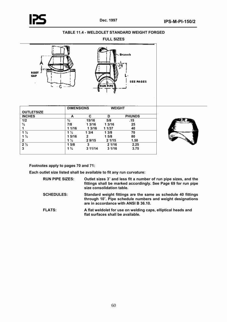
Dec. 1997
IPS-M-PI-150/2
60
TABLE 11.4 - WELDOLET STANDARD WEIGHT FORGED
FULL SIZES
OUTLETSIZE
DIMENSIONS WEIGHT
INCHES A C D PHUNDS 1/2 ¾ 1
¾ 15/16 5/8 .15 7/8 1 3/16 1 3/16 25 1 1/16 1 3/16 1 1/37 40
1 ¼ 1 ½ 2
1 ¼ 1 3/4 1 3/8 70 1 5/16 2 1 5/8 80 1 ½ 2 9/15 2 1/15 1.50
2 ½ 3
1 5/8 3 2 1/16 2.25 1 ¾ 3 11/14 3 1/16 3.75
Footnotes apply to pages 70 and 71:
Each outlet size listed shall be available to fit any run curvature:
RUN PIPE SIZES: Outlet sizes 3” and less fit a number of run pipe sizes, and the fittings shall be marked accordingly. See Page 69 for run pipe size consolidation table.
SCHEDULES: Standard weight fittings are the same as schedule 40 fittings through 10”. Pipe schedule numbers and weight designations are in accordance with ANSI B 36.10.
FLATS: A flat weldolet for use on welding caps, elliptical heads and flat surfaces shall be available.
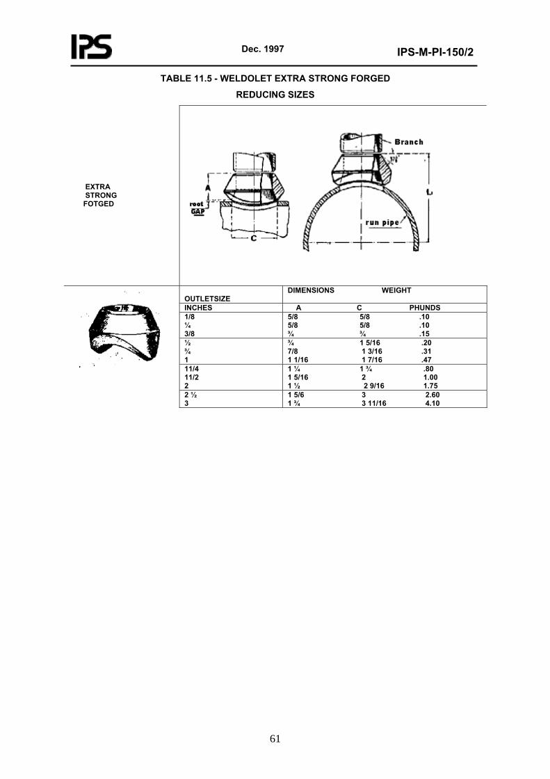
Dec. 1997
IPS-M-PI-150/2
61
TABLE 11.5 - WELDOLET EXTRA STRONG FORGED
REDUCING SIZES EXTRA STRONG FOTGED
OUTLETSIZE
DIMENSIONS WEIGHT
INCHES A C PHUNDS 1/8 ¼ 3/8
5/8 5/8 .10 5/8 5/8 .10 ¾ ¾ .15
½ ¾ 1
¾ 1 5/16 .20 7/8 1 3/16 .31 1 1/16 1 7/16 .47
11/4 11/2 2
1 ¼ 1 ¾ .80 1 5/16 2 1.00 1 ½ 2 9/16 1.75
2 ½ 3
1 5/6 3 2.60 1 ¾ 3 11/16 4.10
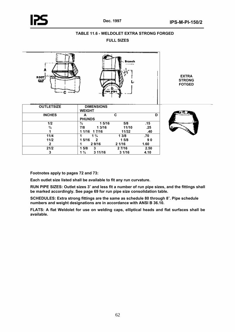
Dec. 1997
IPS-M-PI-150/2
62
TABLE 11.6 - WELDOLET EXTRA STRONG FORGED
FULL SIZES
EXTRA STRONG FOTGED
OUTLETSIZE DIMENSIONS WEIGHT
INCHES A C D PHUNDS
1/2 ¾ 1
¾ 1 5/16 5/8 .15 7/8 1 3/16 11/10 .25 1 1/16 1 7/16 11/32 .40
11/4 11/2
2
1 1 ¾ 1 3/8 .70 1 5/16 2 1 5/8 9 0 1 2 9/16 2 1/16 1.60
21/2 3
1 5/8 3 2 7/16 2.50 1 ¾ 3 11/16 3 1/16 4.10
Footnotes apply to pages 72 and 73:
Each outlet size listed shall be available to fit any run curvature.
RUN PIPE SIZES: Outlet sizes 3” and less fit a number of run pipe sizes, and the fittings shall be marked accordingly. See page 69 for run pipe size consolidation table.
SCHEDULES: Extra strong fittings are the same as schedule 80 through 8”. Pipe schedule numbers and weight designations are in accordance with ANSI B 36.10.
FLATS: A flat Weldolet for use on welding caps, elliptical heads and flat surfaces shall be available.
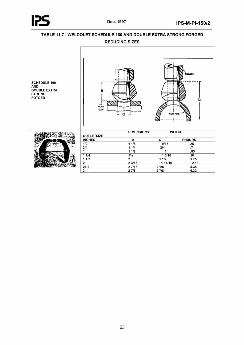
Dec. 1997
IPS-M-PI-150/2
63
TABLE 11.7 - WELDOLET SCHEDULE 160 AND DOUBLE EXTRA STRONG FORGED
REDUCING SIZES SCHEDULE 160 AND DOUBLE EXTRA STRONG FOTGED
OUTLETSIZE
DIMENSIONS WEIGHT
INCHES A C PHUNDS 1/2 3/4 1
1 1/8 9/16 .25 1 1/4 3/4 .71 1 1/2 1 .83
1 1/4 1 1/2 2
1¾ 1 5/16 .18 2 1 1/2 .1.75 2 3/16 1 11/16 2.13
21/2 3
2 7/16 2 1/8 3.38 2 7/8 2 7/8 6.32
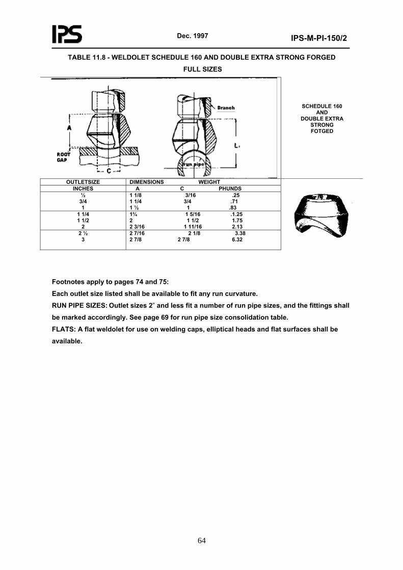
Dec. 1997
IPS-M-PI-150/2
64
TABLE 11.8 - WELDOLET SCHEDULE 160 AND DOUBLE EXTRA STRONG FORGED
FULL SIZES
SCHEDULE 160
AND DOUBLE EXTRA
STRONG FOTGED
OUTLETSIZE DIMENSIONS WEIGHT INCHES A C PHUNDS
½ 3/4 1
1 1/8 3/16 .25 1 1/4 3/4 .71 1 ½ 1 .83
1 1/4 1 1/2
2
1¾ 1 5/16 .1.25 2 1 1/2 1.75 2 3/16 1 11/16 2.13
2 ½ 3
2 7/16 2 1/8 3.38 2 7/8 2 7/8 6.32
Footnotes apply to pages 74 and 75:
Each outlet size listed shall be available to fit any run curvature.
RUN PIPE SIZES: Outlet sizes 2” and less fit a number of run pipe sizes, and the fittings shall
be marked accordingly. See page 69 for run pipe size consolidation table.
FLATS: A flat weldolet for use on welding caps, elliptical heads and flat surfaces shall be
available.
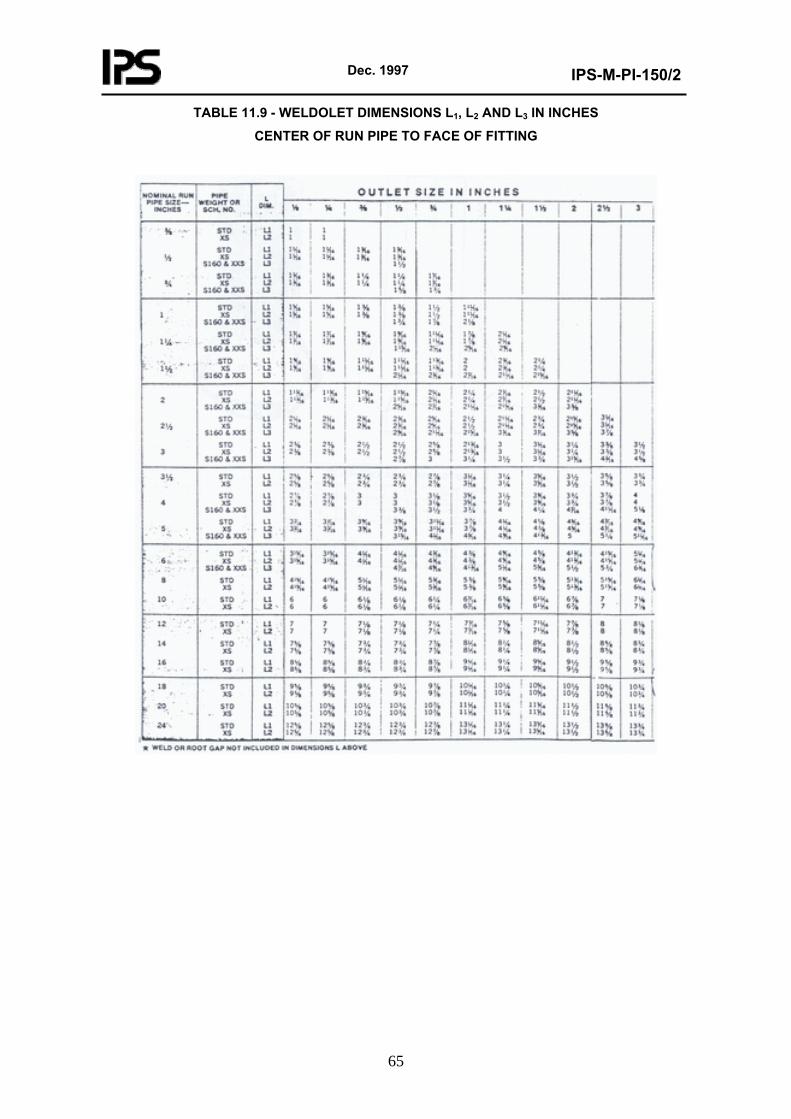
Dec. 1997
IPS-M-PI-150/2
65
TABLE 11.9 - WELDOLET DIMENSIONS L1, L2 AND L3 IN INCHES
CENTER OF RUN PIPE TO FACE OF FITTING
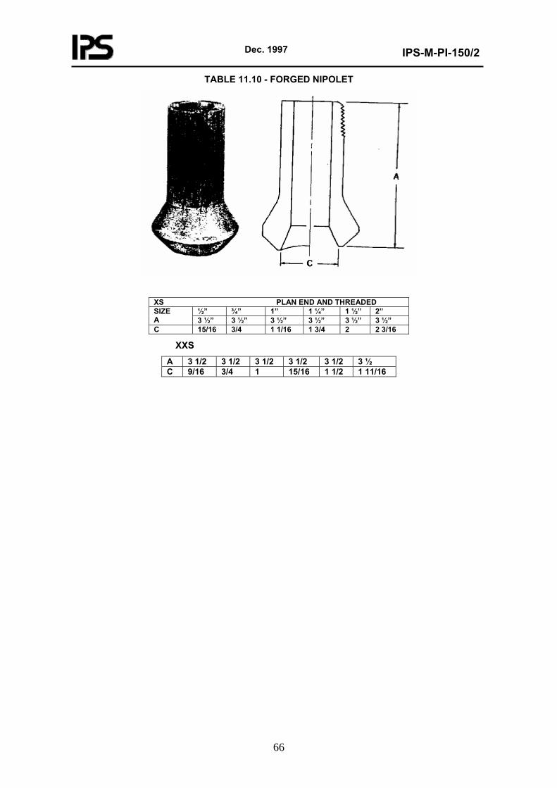
Dec. 1997
IPS-M-PI-150/2
66
TABLE 11.10 - FORGED NIPOLET
XS PLAN END AND THREADED ½” ¾” 1” 1 ¼” 1 ½” 2” SIZE
A 3 ½” 3 ½” 3 ½” 3 ½” 3 ½” 3 ½” C 15/16 3/4 1 1/16 1 3/4 2 2 3/16
XXS A 3 1/2 3 1/2 3 1/2 3 1/2 3 1/2 3 ½ C 9/16 3/4 1 15/16 1 1/2 1 11/16
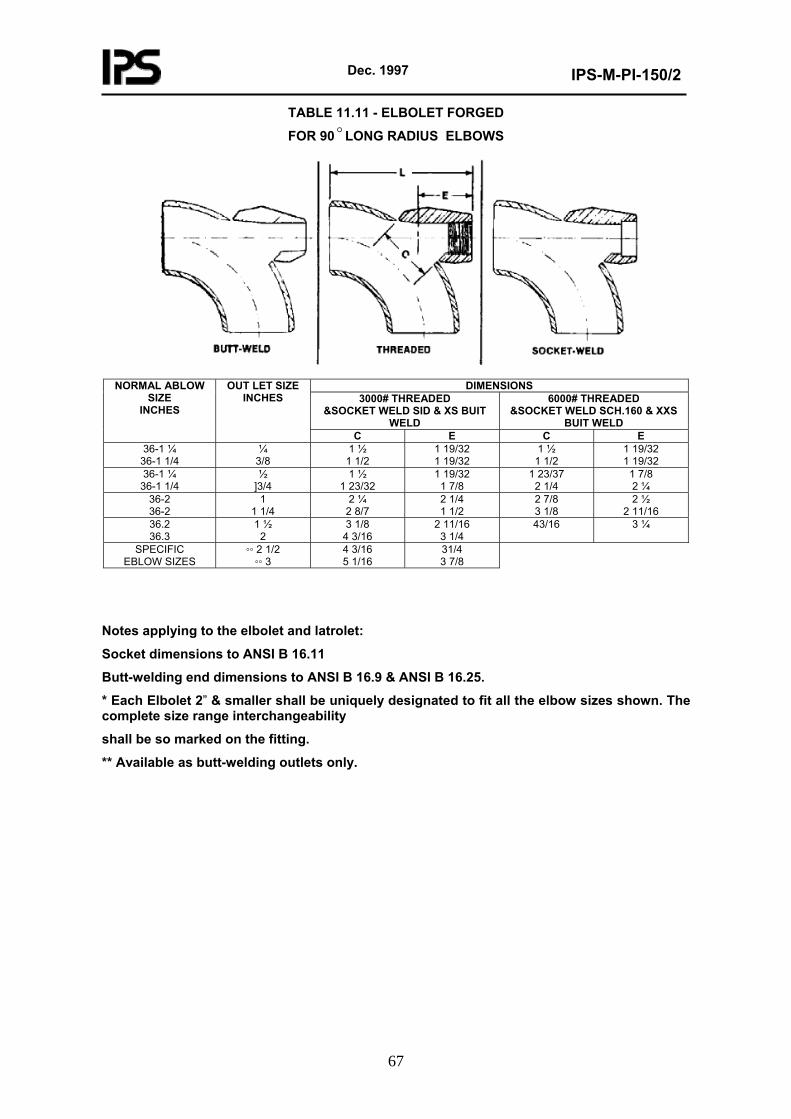
Dec. 1997
IPS-M-PI-150/2
67
TABLE 11.11 - ELBOLET FORGED
FOR 90oLONG RADIUS ELBOWS
DIMENSIONS
3000# THREADED &SOCKET WELD SID & XS BUIT
WELD
6000# THREADED &SOCKET WELD SCH.160 & XXS
BUIT WELD
NORMAL ABLOW SIZE
INCHES
OUT LET SIZE INCHES
C E C E 36-1 ¼
36-1 1/4 ¼
3/8 1 ½
1 1/2 1 19/32 1 19/32
1 ½ 1 1/2
1 19/32 1 19/32
36-1 ¼ 36-1 1/4
½ ]3/4
1 ½ 1 23/32
1 19/32 1 7/8
1 23/37 2 1/4
1 7/8 2 ¼
36-2 36-2
1 1 1/4
2 ¼ 2 8/7
2 1/4 1 1/2
2 7/8 3 1/8
2 ½ 2 11/16
36.2 36.3
1 ½ 2
3 1/8 4 3/16
2 11/16 3 1/4
43/16
3 ¼
SPECIFIC EBLOW SIZES
◦◦ 2 1/2 ◦◦ 3
4 3/16 5 1/16
31/4 3 7/8
Notes applying to the elbolet and latrolet:
Socket dimensions to ANSI B 16.11
Butt-welding end dimensions to ANSI B 16.9 & ANSI B 16.25.
* Each Elbolet 2” & smaller shall be uniquely designated to fit all the elbow sizes shown. The complete size range interchangeability
shall be so marked on the fitting.
** Available as butt-welding outlets only.
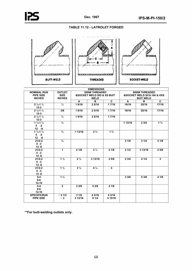
Dec. 1997
IPS-M-PI-150/2
68
TABLE 11.12 - LATROLET FORGED
DIMENSIONS
3000# THREADED &SOCKET WELD SID & XS BUIT
WELD
6000# THREADED &SOCKET WELD SCH.160 & XXS
BUIT WELD
NOMINAL RUN PIPE SIZE INCHES
OUTLET SIZE
INCHES A B C A B C
2 ½-1 ¼ 12-3
¼ 1 9/16 2 5/16 1 7/16 19/16 25/16 17/16
2 ½-1 ¼ 12-3
3/8 1 9/16 2 5/16 1 7/16 19/16 25/16 17/16
2 ½-1 ¼ 12-3
½ 1 9/16 2 5/16 1 7/16
1 ½-1 ¼ 5 -2
12 -6
½ 1 13/16 2 3/4 1 ¾
1 ½-1 ¼ 5 -2
12 -6
¾ 1 13/16 2 ¾ 1 ¾
21/2-2 5 -3 12 -6
¾ 2 1/8 3 1/4 2 1/8
21/2-2 5 -3 12 -6
1 2 1/8 3 ¼ 2 1/8 2 1/2 3 13/16 2 5/8
21/2-2 5 -3 12 -6
1 ¼ 2 ½ 3 13/16 2 5/8 2 3/4 4 1/4 3
21/2-2 5 -3 12 -6
1 ½ 2 ½ 4 ¼ 3
5-4 8-6
12-10
1 ½ 3 3/8 5 3/8 4 1/8
5-4 8-6
12-10
2 3 3/8 5 3/8 4 1/8
SPECIFICRUN PIPE SIZE
◦◦ 2 1/2 ◦◦ 3
3 1/8 3 13/16
4 3/16 6 1/4
4 3/16 4 15/16
**For butt-welding outlets only.
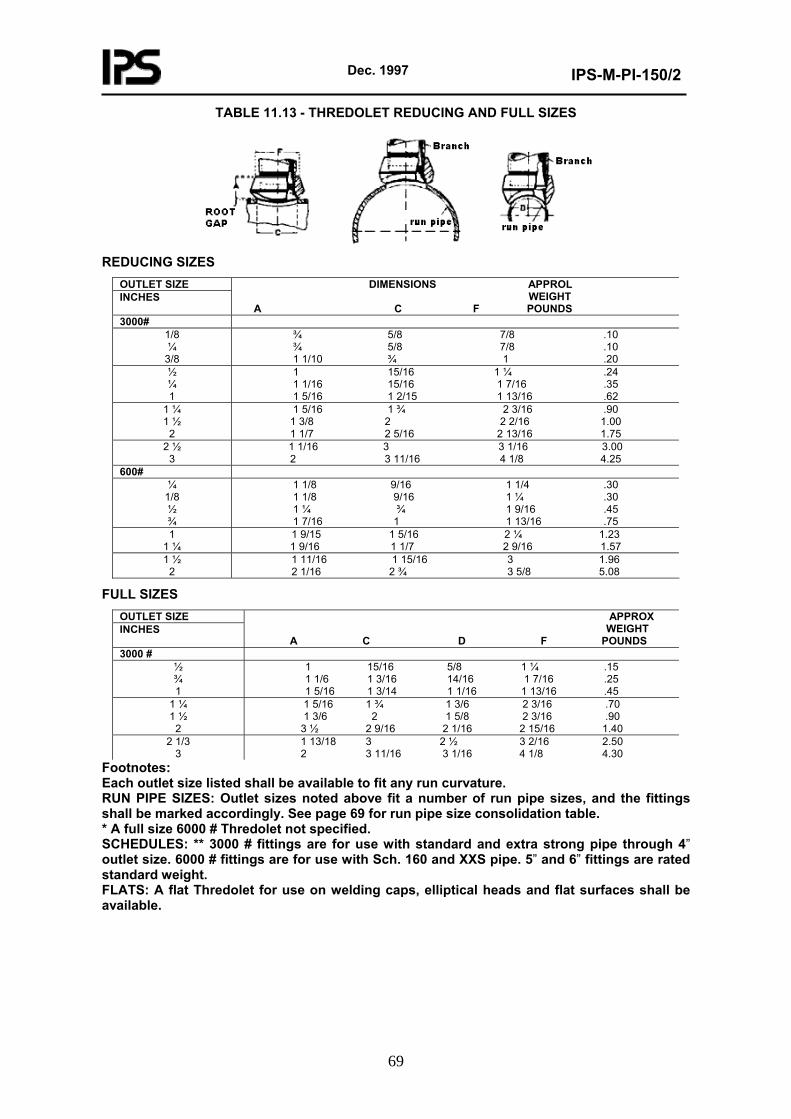
Dec. 1997
IPS-M-PI-150/2
69
TABLE 11.13 - THREDOLET REDUCING AND FULL SIZES
REDUCING SIZES
OUTLET SIZE INCHES
DIMENSIONS APPROL WEIGHT A C F POUNDS
3000# 1/8 ¼
3/8
¾ 5/8 7/8 .10 ¾ 5/8 7/8 .10 1 1/10 ¾ 1 .20
½ ¼ 1
1 15/16 1 ¼ .24 1 1/16 15/16 1 7/16 .35 1 5/16 1 2/15 1 13/16 .62
1 ¼ 1 ½
2
1 5/16 1 ¾ 2 3/16 .90 1 3/8 2 2 2/16 1.00 1 1/7 2 5/16 2 13/16 1.75
2 ½ 3
1 1/16 3 3 1/16 3.00 2 3 11/16 4 1/8 4.25
600# ¼
1/8 ½ ¾
1 1/8 9/16 1 1/4 .30 1 1/8 9/16 1 ¼ .30 1 ¼ ¾ 1 9/16 .45 1 7/16 1 1 13/16 .75
1 1 ¼
1 9/15 1 5/16 2 ¼ 1.23 1 9/16 1 1/7 2 9/16 1.57
1 ½ 2
1 11/16 1 15/16 3 1.96 2 1/16 2 ¾ 3 5/8 5.08
FULL SIZES OUTLET SIZE INCHES
APPROX WEIGHT A C D F POUNDS
3000 # ½ ¾ 1
1 15/16 5/8 1 ¼ .15 1 1/6 1 3/16 14/16 1 7/16 .25 1 5/16 1 3/14 1 1/16 1 13/16 .45
1 ¼ 1 ½
2
1 5/16 1 ¾ 1 3/6 2 3/16 .70 1 3/6 2 1 5/8 2 3/16 .90
3 ½ 2 9/16 2 1/16 2 15/16 1.40 2 1/3
3 1 13/18 3 2 ½ 3 2/16 2.50 2 3 11/16 3 1/16 4 1/8 4.30
Footnotes: Each outlet size listed shall be available to fit any run curvature. RUN PIPE SIZES: Outlet sizes noted above fit a number of run pipe sizes, and the fittings shall be marked accordingly. See page 69 for run pipe size consolidation table. * A full size 6000 # Thredolet not specified. SCHEDULES: ** 3000 # fittings are for use with standard and extra strong pipe through 4” outlet size. 6000 # fittings are for use with Sch. 160 and XXS pipe. 5” and 6” fittings are rated standard weight. FLATS: A flat Thredolet for use on welding caps, elliptical heads and flat surfaces shall be available.
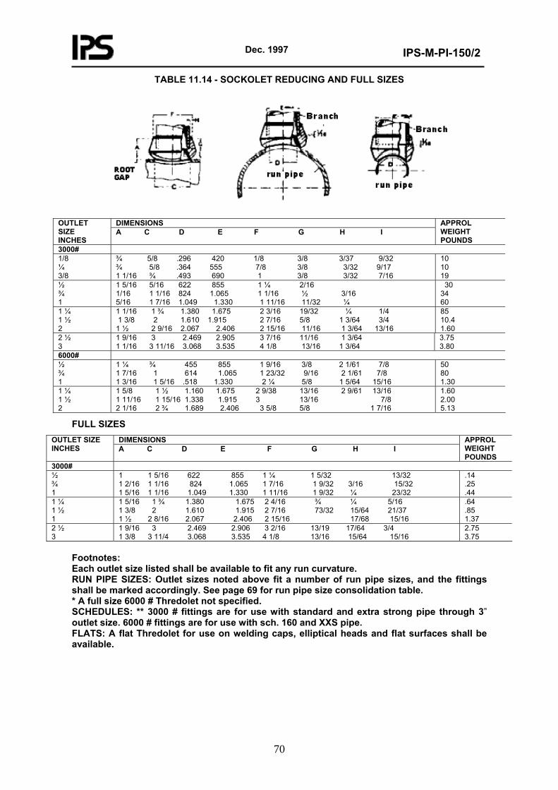
Dec. 1997
IPS-M-PI-150/2
70
TABLE 11.14 - SOCKOLET REDUCING AND FULL SIZES
DIMENSIONS OUTLET
SIZE INCHES
A C D E F G H I APPROL WEIGHT POUNDS
3000# 1/8 ¼ 3/8
¾ 5/8 .296 420 1/8 3/8 3/37 9/32 ¾ 5/8 .364 555 7/8 3/8 3/32 9/17 1 1/16 ¾ .493 690 1 3/8 3/32 7/16
10 10 19
½ ¾ 1
1 5/16 5/16 622 855 1 ¼ 2/16 1/16 1 1/16 824 1.065 1 1/16 ½ 3/16 5/16 1 7/16 1.049 1.330 1 11/16 11/32 ¼
30 34 60
1 ¼ 1 ½ 2
1 1/16 1 ¾ 1.380 1.675 2 3/16 19/32 ¼ 1/4 1 3/8 2 1.610 1.915 2 7/16 5/8 1 3/64 3/4 1 ½ 2 9/16 2.067 2.406 2 15/16 11/16 1 3/64 13/16
85 10.4 1.60
2 ½ 3
1 9/16 3 2.469 2.905 3 7/16 11/16 1 3/64 1 1/16 3 11/16 3.068 3.535 4 1/8 13/16 1 3/64
3.75 3.80
6000# ½ ¾ 1
1 ¼ ¾ 455 855 1 9/16 3/8 2 1/61 7/8 1 7/16 1 614 1.065 1 23/32 9/16 2 1/61 7/8 1 3/16 1 5/16 .518 1.330 2 ¼ 5/8 1 5/64 15/16
50 80 1.30
1 ¼ 1 ½ 2
1 5/8 1 ½ 1.160 1.675 2 9/38 13/16 2 9/61 13/16 1 11/16 1 15/16 1.338 1.915 3 13/16 7/8 2 1/16 2 ¾ 1.689 2.406 3 5/8 5/8 1 7/16
1.60 2.00 5.13
FULL SIZES DIMENSIONS OUTLET SIZE
INCHES A C D E F G H I APPROL WEIGHT POUNDS
3000# ½ ¾ 1
1 1 5/16 622 855 1 ¼ 1 5/32 13/32 1 2/16 1 1/16 824 1.065 1 7/16 1 9/32 3/16 15/32 1 5/16 1 1/16 1.049 1.330 1 11/16 1 9/32 ¼ 23/32
.14
.25
.44 1 ¼ 1 ½ 1
1 5/16 1 ¾ 1.380 1.675 2 4/16 ¾ ¼ 5/16 1 3/8 2 1.610 1.915 2 7/16 73/32 15/64 21/37 1 ½ 2 8/16 2.067 2.406 2 15/16 17/68 15/16
.64
.85 1.37
2 ½ 3
1 9/16 3 2.469 2.906 3 2/16 13/19 17/64 3/4 1 3/8 3 11/4 3.068 3.535 4 1/8 13/16 15/64 15/16
2.75 3.75
Footnotes: Each outlet size listed shall be available to fit any run curvature. RUN PIPE SIZES: Outlet sizes noted above fit a number of run pipe sizes, and the fittings shall be marked accordingly. See page 69 for run pipe size consolidation table. * A full size 6000 # Thredolet not specified. SCHEDULES: ** 3000 # fittings are for use with standard and extra strong pipe through 3” outlet size. 6000 # fittings are for use with sch. 160 and XXS pipe. FLATS: A flat Thredolet for use on welding caps, elliptical heads and flat surfaces shall be available.
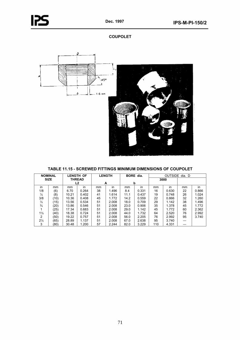
Dec. 1997
IPS-M-PI-150/2
71
COUPOLET
TABLE 11.15 - SCREWED FITTINGS MINIMUM DIMENSIONS OF COUPOLET
OUTSIDE dia. D NOMINAL SIZE
LENGTH OF THREAD
L2
LENGTH
A
BORE dia.
b 3000
in 1/8 ¼
3/8 ½ ¾ 1
1½ 2
2½ 3
mm (6) (8)
(10) (15) (20) (25) (40) (50) (65) (80)
mm 6.70
10.21 10.36 13.56 13.86 17.34 18.38 19.22 28.89 30.48
in 0.264 0.402 0.408 0.534 0.546 0.683 0.724 0.757 1.137 1.200
mm 38 41 45 51 51 51 51 51 51 57
in 1.496 1.614 1.772 2.008 2.008 2.008 2.008 2.008 2.008 2.244
mm 8.4
11.1 14.2 18.0 23.0 29.0 44.0 56.0 67.0 82.0
in 0.331 0.437 0.559 0.709 0.906 1.142 1.732 2.205 2.638 3.229
mm 16 19 22 29 35 45 64 76 95
110
in 0.630 0.748 0.866 1.142 1.378 1.772 2.520 2.992 3.740 4.331
mm 22 26 32 38 45 60 76 95 --- ---
in 0.866 1.024 1.260 1.496 1.772 2.362 2.992 3.740
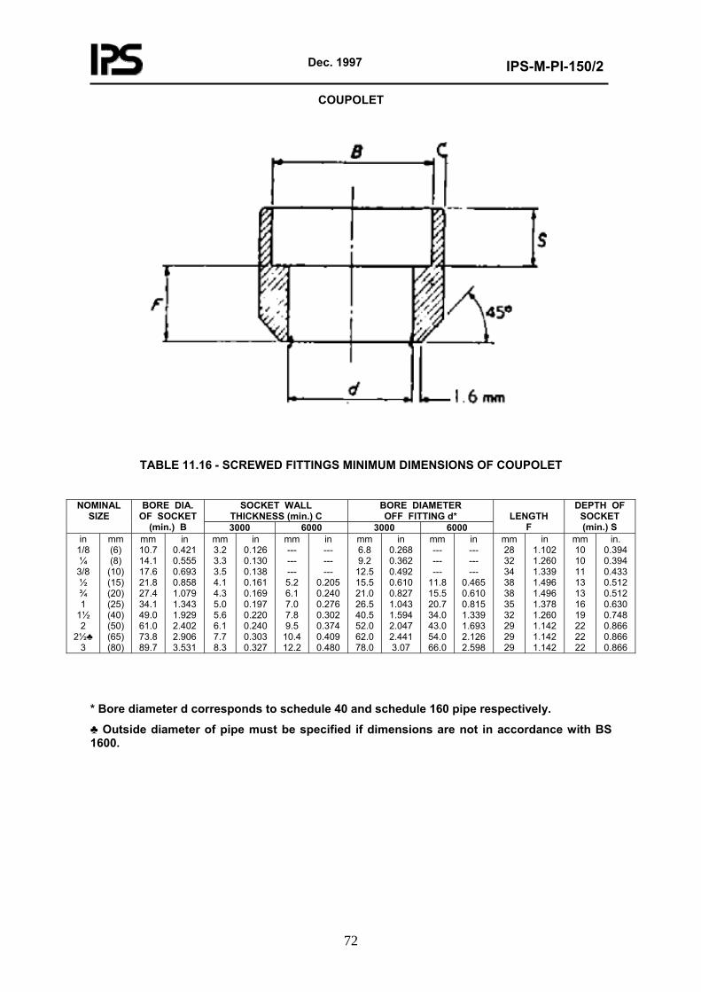
Dec. 1997
IPS-M-PI-150/2
72
COUPOLET
TABLE 11.16 - SCREWED FITTINGS MINIMUM DIMENSIONS OF COUPOLET
SOCKET WALL
THICKNESS (min.) C BORE DIAMETER OFF FITTING d*
NOMINAL SIZE
BORE DIA. OF SOCKET
(min.) B 3000 6000 3000 6000
LENGTH
F
DEPTH OF SOCKET (min.) S
in 1/8 ¼
3/8 ½ ¾ 1
1½ 2
2½♣ 3
mm (6) (8)
(10) (15) (20) (25) (40) (50) (65) (80)
mm 10.7 14.1 17.6 21.8 27.4 34.1 49.0 61.0 73.8 89.7
in 0.421 0.555 0.693 0.858 1.079 1.343 1.929 2.402 2.906 3.531
mm 3.2 3.3 3.5 4.1 4.3 5.0 5.6 6.1 7.7 8.3
in 0.126 0.130 0.138 0.161 0.169 0.197 0.220 0.240 0.303 0.327
mm --- --- --- 5.2 6.1 7.0 7.8 9.5
10.4 12.2
in --- --- ---
0.205 0.240 0.276 0.302 0.374 0.409 0.480
mm 6.8 9.2
12.5 15.5 21.0 26.5 40.5 52.0 62.0 78.0
in 0.268 0.362 0.492 0.610 0.827 1.043 1.594 2.047 2.441 3.07
mm --- --- ---
11.8 15.5 20.7 34.0 43.0 54.0 66.0
in --- --- ---
0.465 0.610 0.815 1.339 1.693 2.126 2.598
mm 28 32 34 38 38 35 32 29 29 29
in 1.102 1.260 1.339 1.496 1.496 1.378 1.260 1.142 1.142 1.142
mm 10 10 11 13 13 16 19 22 22 22
in. 0.394 0.394 0.433 0.512 0.512 0.630 0.748 0.866 0.866 0.866
* Bore diameter d corresponds to schedule 40 and schedule 160 pipe respectively.
♣ Outside diameter of pipe must be specified if dimensions are not in accordance with BS 1600.
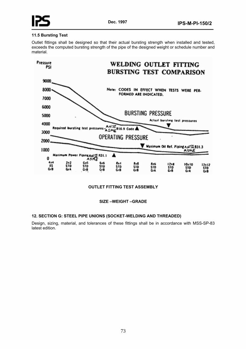
Dec. 1997
IPS-M-PI-150/2
73
11.5 Bursting Test
Outlet fittings shall be designed so that their actual bursting strength when installed and tested, exceeds the computed bursting strength of the pipe of the designed weight or schedule number and material.
OUTLET FITTING TEST ASSEMBLY
SIZE –WEIGHT –GRADE
12. SECTION G: STEEL PIPE UNIONS (SOCKET-WELDING AND THREADED)
Design, sizing, material, and tolerances of these fittings shall be in accordance with MSS-SP-83 latest edition.