fitting instructions fifth gear upgrade - monte hospitalmontehospital.com/shop/mh4700.pdf · title:...
TRANSCRIPT
Please read the instructions fully to make sure
you have everything on hand before starting.
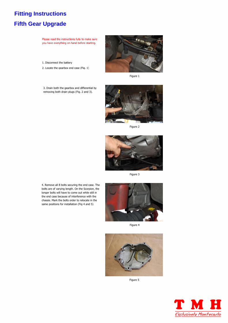
1. Disconnect the battery
2. Locate the gearbox end case (Fig. 1)
3. Drain both the gearbox and differential by
removing both drain plugs (Fig. 2 and 3).
4. Remove all 8 bolts securing the end case. The
bolts are of varying length. On the Scorpion, the
longer bolts will have to come out while still in
the end case because of interference with the
chassis. Mark the bolts order to relocate in the
same positions for installation (Fig 4 and 5).
Figure 1
Figure 2
Figure 3
Figure 4
Figure 5
Fitting Instructions
Fifth Gear Upgrade

5. Once the end case is removed, you will clearly
see the two 5th gears (Fig. 6) and the shift fork.
The gears are held by two special ring nuts with
4 indentations. The nuts are also crimped to the
shafts at 2 points around their circumference.
In order to remove and install the nuts, you
need a special four-legged tool that can be
fabricated by grinding a 1 1/16 inch socket (fig.
7). It is recommended that your order a pair of
special nuts before attempting to fabricate the
tool. This will help to ensure that you grind the
socket properly and that it fits the nut well
before you attempt to dismantle the gears
6. Before attempting to remove the nuts, you
must straighten both crimped sections on each
nut with a center punch. DO NOT ATTEMPT TO
REMOVE THE NUTS BEFORE PROPERLY
STRAIGHTENING THE CRIMPED SECTIONS.
OTHERWISE YOU RISK RUINING THE SHAFT
THREADS.
7. If you have difficulty loosening the special
nuts with the fabricated socket, you can do this
by carefully using a straight punch and hammer
by positioning the punch radially, as seen on Fig.
8. A couple of sharp hammer blows on the
punch should loosen the nut which can then be
removed with the special tool.
8. Remove the bolt securing the shift fork to its
shaft (Fig. 9). Make sure the synchro ring on the
primary shaft (on the right side of Fig. 9) is in
the disengaged position, that is pulled back from
the gear box. This is necessary so that the
springs, balls and pins do not jump out of the
synchro. Hold the gear and synchro assembly
firmly together and carefully slide the assembly
off the shaft. Should the balls and springs jump
out of the synchro, you will have to use patience
to put them back in before reassembly.
9. Remove the ring nut from the end of the
mainshaft and remove the gear (left side of Fig.
9).
10. Note on Fig. 10 that 3 of the hex bolts (8M
1.25) securing the retaining plate behind the
gears have been replaced with 3 Allen-head
bolts in order to allow the larger gear to clear
the bolts. Allen-head metric bolts (Fig. 12) are
available at Ace Hardware. Make sure you install
the new Allen-head bolts at this stage.
11. In order to clear larger gear, it is also
necessary to grind the shift fork as seen on Fig.
10. DO NOT overdo it. To make sure the fork
clears the gear teeth, install the fork all the way
in on its shaft and turn the gear by hand to
check that it is not touching the fork.
12. Remove the fork.
13. Start reassembly by fitting the new larger
5th gear larger to the primary shaft (upper one
on Fig. 10).
Figure 6
Figure 7
Figure 8
Figure 9
Figure 10
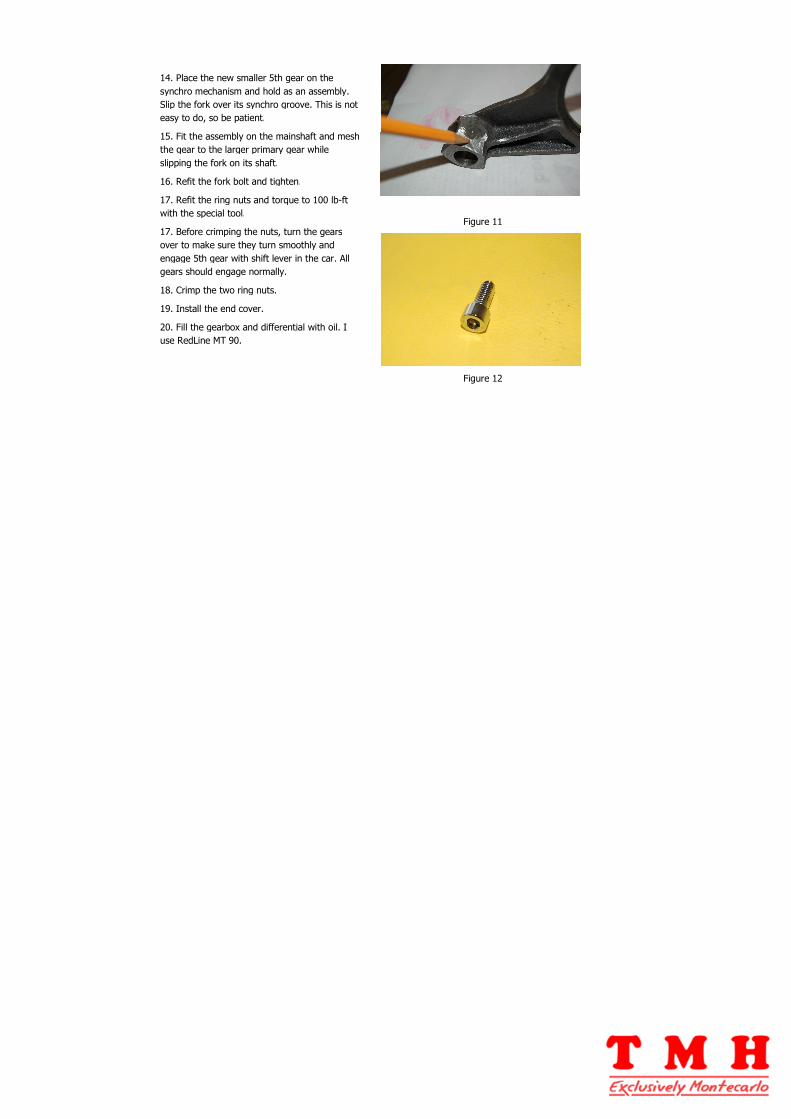
14. Place the new smaller 5th gear on the
synchro mechanism and hold as an assembly.
Slip the fork over its synchro groove. This is not
easy to do, so be patient.
15. Fit the assembly on the mainshaft and mesh
the gear to the larger primary gear while
slipping the fork on its shaft.
16. Refit the fork bolt and tighten.
17. Refit the ring nuts and torque to 100 lb-ft
with the special tool.
17. Before crimping the nuts, turn the gears
over to make sure they turn smoothly and
engage 5th gear with shift lever in the car. All
gears should engage normally.
18. Crimp the two ring nuts.
19. Install the end cover.
20. Fill the gearbox and differential with oil. I
use RedLine MT 90.
Figure 11
Figure 12