fitting instructions - atlantics manual... · installation must comply with the nf c 15-100...
TRANSCRIPT

FITTING INSTRUCTIONS
OPTIMOCOSY HR
412203
Family 4No. 4100Index No.Date 04/2015
2
1. WARNINGS ........................................................ 3
2. DESCRIPTION ..................................................... 3
2.1 General ........................................................ 3
2.2. Component parts ........................................ 3
2.3. Technical specifications ................................. 4
3. INSTALLING / FITTING THE PRODUCT .............. 4
3.1. Installation location ....................................... 4
3.2. Fitting to vertical wall .................................... 4
3.3. Air connections and associated terminations ......................... 5
3.4. Condensate connections ............................... 7
4. ELECTRICAL CONNECTIONS ............................. 8
5. START UP ........................................................... 9
5.1. Installing the 2 AA LR6 batteries ................... 9
5.2. Overview of the remote control .................... 9
5.3. Locking and unlocking the remote control .. 10
5.4. Settings ..................................................... 10
5.5. First use settings ......................................... 10
5.6. Overview of the LCD screen ....................... 12
5.7. Setting the time and date ........................... 12
5.8. Waking up the remote control .................... 13
5.9. Ventilation mode ........................................ 13
5.10. Manual ventilation mode.......................... 13
5.11. Programmed ventilation mode ................. 14
5.12. Quick boost.............................................. 15
5.13. Adjusting the auto cooling boost.............. 16
5.14. Controlling the OPTIMOCOSY according to CO2 level .......................................................... 17
5.15. Air quality and comfort level ..................... 17
5.16. Energy savings.......................................... 18
5.17. Adjusting night-time ventilation ............... 19
5.18. Away Mode ............................................. 20
6. INSTALLER MODE ........................................... 20
6.1. Resetting the start-up sequence .................. 20
6.2. Testing the installation ................................ 20
6.3. Adjusting the imbalance ............................. 22
6.4. Adjusting the away air flow ........................ 22
6.5. Adjusting the BY-PASS settings.................... 23
6.6. Earth-to-air heat exchanger wiring and settings ............................................................. 24
6.7. Frost protection device wiring and settings ............................................................. 26
7. SERVICING ....................................................... 27
7.1. Changing the filters .................................... 27
7.2. Cleaning the heat exchanger and the turbine blades ............................................................... 29
8. BREAKDOWNS AND FAULTS .......................... 30
9. GUARANTEE .................................................... 32
10. PROTECTING THE ENVIRONMENT ................ 32
CONTENTS
3
1. WARNINGS CAUTION:
This device is not intended to be used by persons (including children) with disabilities whether physical, mental or affecting their senses, or persons without the requisite knowledge or experience unless they have been supervised or instructed in using the device by someone responsible for their safety beforehand.Children should be monitored to prevent them from playing with the device.
2. DESCRIPTION2.1. General
Highly efficient dual flow ventilation system for private homes.
Our dual flow ventilation system blows fresh air into the living areas (bedrooms, sitting room, study) and extracts stale air from humid areas (kitchen, bathroom, toilet).The air is distributed and extracted via a network of ducts.
Fresh air from outside is filtered and pre-heated when it passes over a highly efficient heat exchanger which recovers the energy from the extracted air without allowing it to mix with the fresh air.• Remote controlled.• Thermal efficiency: 91%• Low consumption motors.• Complete fresh air by-pass providing optimum natural cooling in summer.• Condensate removal via automatically-filled integrated syphon.
Boost function: Increased air flows for improved cooling.Facility for controlling an earth-to-air heat exchanger. Numerous interface options.
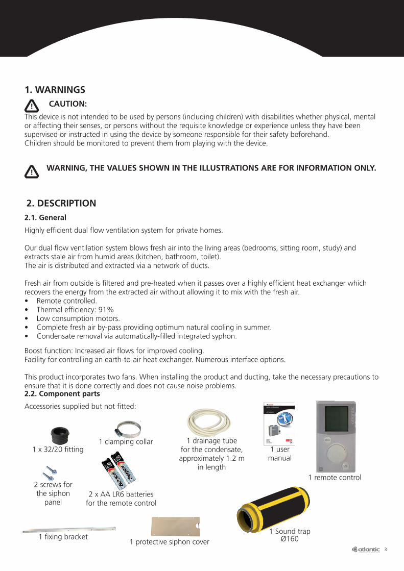
2.2. Component parts
Accessories supplied but not fitted:
This product incorporates two fans. When installing the product and ducting, take the necessary precautions to ensure that it is done correctly and does not cause noise problems.
1 clamping collar
1 fixing bracket
1 remote control
1 drainage tube for the condensate, approximately 1.2 m
in length
1 Sound trap Ø160
1 x 32/20 fitting
WARNING, THE VALUES SHOWN IN THE ILLUSTRATIONS ARE FOR INFORMATION ONLY.
!
!
2 screws for the siphon
panel
1 protective siphon cover
2 x AA LR6 batteriesfor the remote control
1 user manual
4
2.3. Technical specifications
Max air flow 300 m3/h @ 100 Pa.
Electrical characteristics:
•Electricalpower:20.1to67.8W-Th-C.•Maxpower:200Wforthe2fans(Maxcurrent=1A)•FortheoptionalBEToutputwiring:totalmaxpower=800W(maxcurrent=3.5A)
3. INSTALLING / FITTING THE PRODUCT
3.1. Installation location
The main unit must be installed vertically in the habitable area of the home and not in the loft. Wherever possible, the ducts should be installed in the heated area. Failing this, they should be insulated with a mini-mum of 50 mm of glass wool. If the above conditions are not met, the performance of the dual flow ventila-tion system will suffer, especially in terms of thermal efficiency.
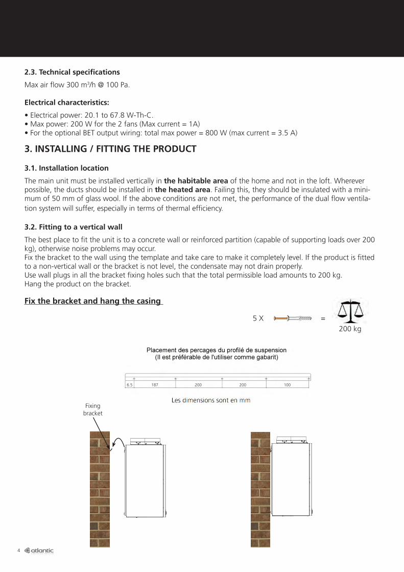
3.2. Fitting to a vertical wall
The best place to fit the unit is to a concrete wall or reinforced partition (capable of supporting loads over 200 kg), otherwise noise problems may occur.Fix the bracket to the wall using the template and take care to make it completely level. If the product is fitted to a non-vertical wall or the bracket is not level, the condensate may not drain properly.Use wall plugs in all the bracket fixing holes such that the total permissible load amounts to 200 kg.Hang the product on the bracket.
Fix the bracket and hang the casing
200 kg5 X =
6.5 187 200 200 100
Fixing bracket

5
3.3. Air connections and associated terminations
The best place to install the ducts is in the habitable area. Make sure you use ducts with 50 mm of glass wool insulation for the cold air flows: - Fresh Air Intake- Stale Air Exhaust
The cardboard insert can be used as a template to drill the duct holes in the ceiling.
112 161 206 161
143
144 148
138
Stale air Exhaust
port
Stale air Intake port
Fresh air Outlet port
Fresh air Intake port
The device nameplate must be clearly accessible from the outside. Ensure there is enough space to be able to get at it and pass the details on to the technicians in case of problems. The data should be copied into the user manual.
Make sure you place the template on the ceiling with the writing facing upwards
Nameplate
Allow for 300 mm clearance
!
!
6
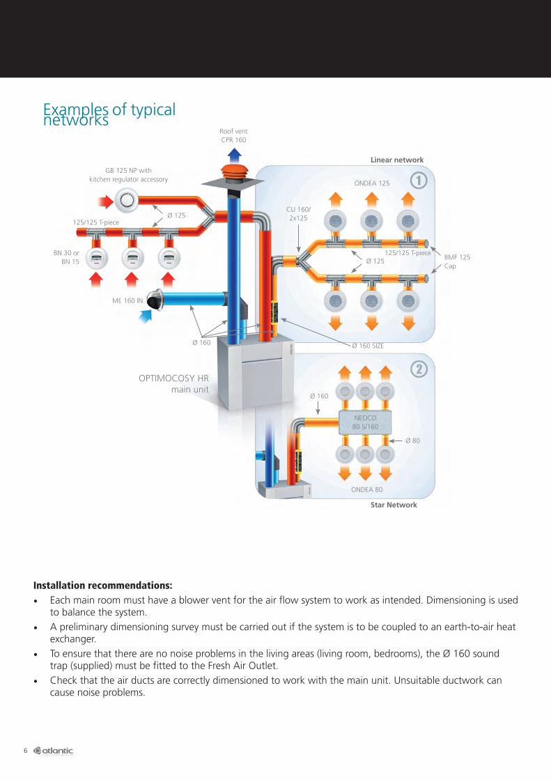
Installation recommendations:• Each main room must have a blower vent for the air flow system to work as intended. Dimensioning is used
to balance the system.• A preliminary dimensioning survey must be carried out if the system is to be coupled to an earth-to-air heat
exchanger.• To ensure that there are no noise problems in the living areas (living room, bedrooms), the Ø 160 sound
trap (supplied) must be fitted to the Fresh Air Outlet.• Check that the air ducts are correctly dimensioned to work with the main unit. Unsuitable ductwork can
cause noise problems.
Examples of typical networks
Roof vent CPR 160
GB 125 NP withkitchen regulator accessory
Ø 125125/125 T-piece
ME 160 IN
Ø 160 Ø 160 SIZE
CU 160/ 2x125
Ø 125 BMF 125Cap
125/125 T-piece
ONDEA 125
ONDEA 80
OPTIMOCOSY HRmain unit
Ø 160
Ø 80
NEOCD 80 S/160
Linear network
Star Network
BN 30 or BN 15
7
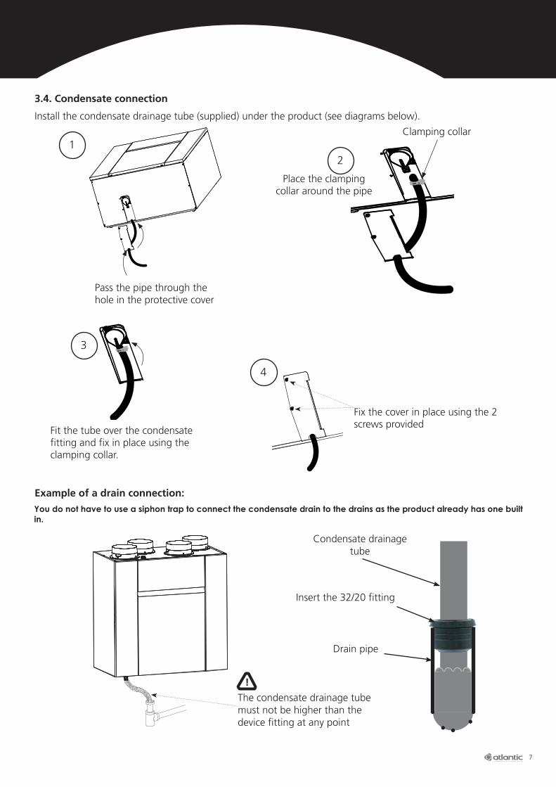
3.4. Condensate connection
Install the condensate drainage tube (supplied) under the product (see diagrams below).
Example of a drain connection:
Place the clamping collar around the pipe
Clamping collar
Pass the pipe through the hole in the protective cover
12
Fit the tube over the condensate fitting and fix in place using the clamping collar.
3
Fix the cover in place using the 2 screws provided
4
You do not have to use a siphon trap to connect the condensate drain to the drains as the product already has one built in.
The condensate drainage tube must not be higher than the device fitting at any point
Condensate drainage tube
Insert the 32/20 fitting
Drain pipe
!
8
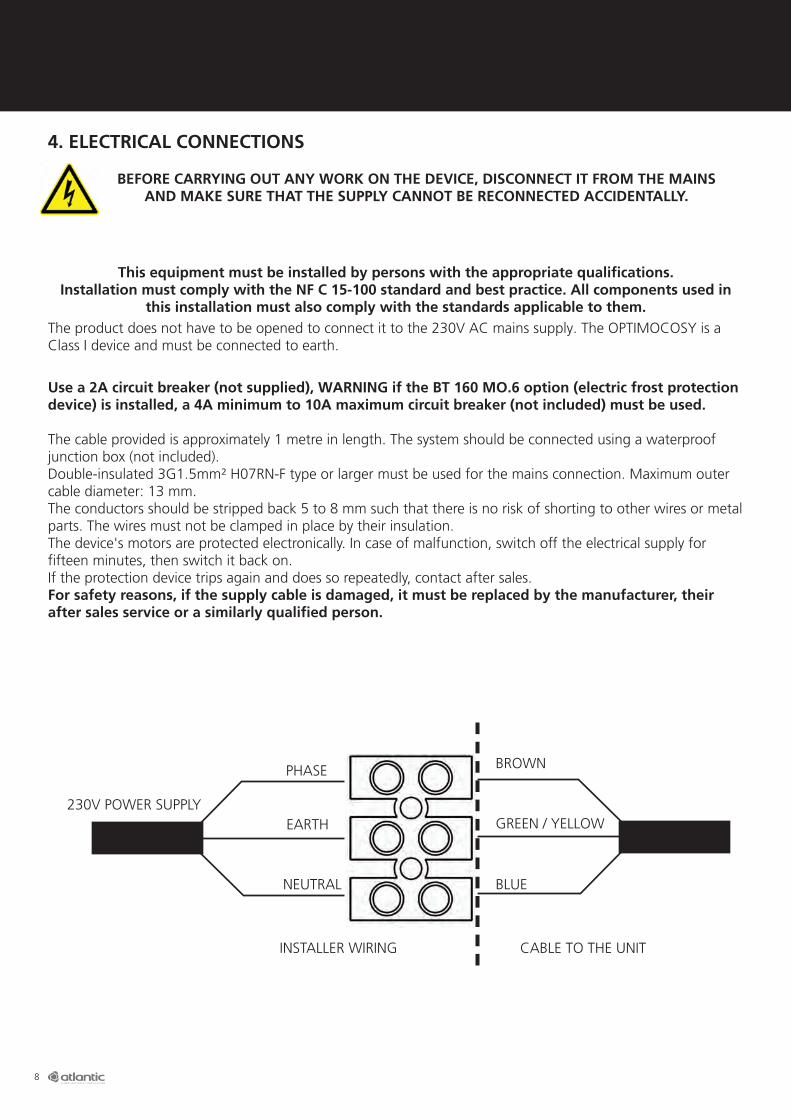
4. ELECTRICAL CONNECTIONS
BEFORE CARRYING OUT ANY WORK ON THE DEVICE, DISCONNECT IT FROM THE MAINS AND MAKE SURE THAT THE SUPPLY CANNOT BE RECONNECTED ACCIDENTALLY.
This equipment must be installed by persons with the appropriate qualifications.Installation must comply with the NF C 15-100 standard and best practice. All components used in
this installation must also comply with the standards applicable to them.The product does not have to be opened to connect it to the 230V AC mains supply. The OPTIMOCOSY is a Class I device and must be connected to earth.
Use a 2A circuit breaker (not supplied), WARNING if the BT 160 MO.6 option (electric frost protection device) is installed, a 4A minimum to 10A maximum circuit breaker (not included) must be used. The cable provided is approximately 1 metre in length. The system should be connected using a waterproof junction box (not included).Double-insulated 3G1.5mm² H07RN-F type or larger must be used for the mains connection. Maximum outer cable diameter: 13 mm. The conductors should be stripped back 5 to 8 mm such that there is no risk of shorting to other wires or metal parts. The wires must not be clamped in place by their insulation.The device's motors are protected electronically. In case of malfunction, switch off the electrical supply for fifteen minutes, then switch it back on. If the protection device trips again and does so repeatedly, contact after sales.For safety reasons, if the supply cable is damaged, it must be replaced by the manufacturer, their after sales service or a similarly qualified person.
BROWNPHASE
GREEN / YELLOWEARTH
NEUTRAL
CABLE TO THE UNITINSTALLER WIRING
BLUE
230V POWER SUPPLY

9
5. START UP5.1. Installing the 2 AA LR6 batteries
For increased savings and convenience, your OPTIMOCOSY is equipped with a remote control so that you can control all the device's functions remotely:• boost general home ventilation• reduce ventilation flows during prolonged absences• choose between automatic, manual and boost modes• display system information (state of the filters, intake / outlet temperature, system efficiency, etc.).
MENU button RETURN buttonScroll wheel and confirm button
WARNING, THE VALUES SHOWN IN THE
ILLUSTRATIONS ARE FOR INFORMATION ONLY.
!
5.2. Overview of the remote control
Push the tab inwards to release the catches Insert the batteries taking care to observe the correct polarity (shown on the holders)
Wall fixingTo fix the control to the wall, first detach the wall mount on the back. Now fix the mount to the wall using the appropriate screws and wall plugs (not included) for the type of wall.

10
Press the centre of the scroll wheel to confirm the data
When running the system for the first time, you will be asked to enter certain parameters for your home from a pre-programmed list.
Select the desired language by turning the remote control scroll wheel and pressing it to confirm your selection.
Select the desired date and time by turning the remote control scroll wheel and pressing it to confirm your selection.
Confirm this step by pressing the scroll wheel.
5.4. Settings
5.3. Verrouillage déverrouillage de la télécommande [Locking and unlocking the remote control]
5.5 Paramètrage de première mise en route [First use settings]
The range of the remote control can vary in relation to the obstacles encountered (walls, floors, etc.). In most cases, the remote control's range is sufficient for it to be used anywhere in the home. However, there are a few recommendations that should be followed to ensure that your CMV system works properly.
Recommendations:•Theremotecontrolmustnotbeexposedtosourcesofmoisture(showers,washbasins,etc.).•Themaximumrecommendedambienttemperaturearoundtheremotecontrolmustnotexceed40°Conacontinuousbasis.•Toensurethattheremotecontrolworkscorrectly,werecommendthatitisnotplacedonorfixedtoanymetalsurface.
OK
Date et heure [Date and time]
Language setting
Navigation reminder
MENU Press the MENU button 3 times to lock or unlock the remote control

11
Configuration logement / Pièces avec amenée air neuf [Home configuration / Rooms with fresh air vents]
Configuration logement / Pièces d’extraction air vicié [Home configuration / Rooms with stale air vents]
Paramétrages option / Puits canadien [Option settings / Earth-to-air heat exchanger]
Paramétrages option /Batterie électrique antigivrage [Option settings / Electric frost protection device]
Informations bilan des paramètrages [Settings summary]
Choose the number of main rooms in the home (salle à manger, salon, chambres [dining room, living room, bedrooms, etc.]). Confirm your choice by pressing the scroll wheel.
Select the number of bouches d'amenée d'air [blown air vents] in the home. Confirm your choice by pressing the scroll wheel.NB: do not count the vents in bathrooms, kitchens, toilets or wet rooms as these are extraction vents.
Choose the number of kitchens (maximum 1 kitchen), toilets, bathrooms or other wet rooms (laundry room, cellar, etc.). Confirm your choice by pressing the scroll wheel.
Choose this option if you have an earth-to-air heat exchanger. Confirm your choices by pressing the scroll wheel.
For information on how to install an earth-to-air heat exchanger, see chapter XXX pXX
Choose this option if you have an electric frost protection device. Confirm your choices by pressing the scroll wheel.
For information on how to install an electric frost protection device, see chapter XXX pXX
This screen displays the data you have just entered.
If you have made a mistake, you can go back by pressing the RETURN button.
If all the entries are correct, confirm by pressing the scroll wheel.
Paramètrages
Batterie électrique antigivrage
Options
12
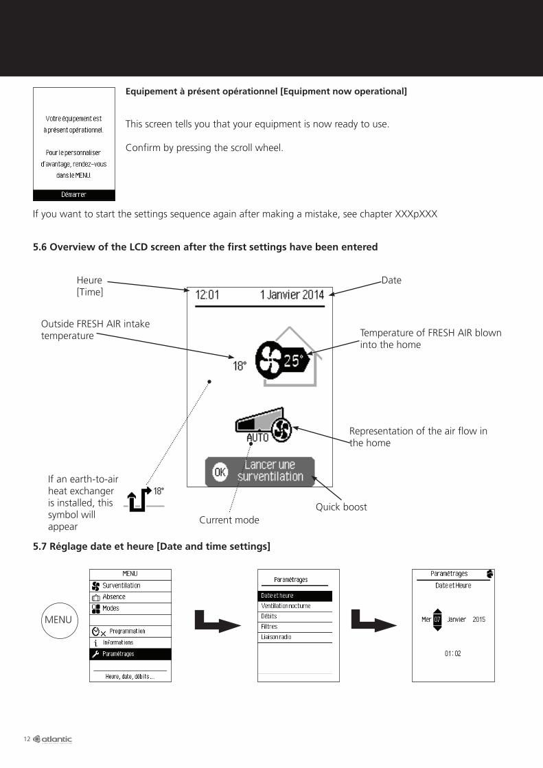
Equipement à présent opérationnel [Equipment now operational]
This screen tells you that your equipment is now ready to use.
Confirm by pressing the scroll wheel.
If you want to start the settings sequence again after making a mistake, see chapter XXXpXXX
Heure [Time]
Date
Outside FRESH AIR intake temperature Temperature of FRESH AIR blown
into the home
Representation of the air flow in the home
Quick boostCurrent mode
5.6 Overview of the LCD screen after the first settings have been entered
5.7 Réglage date et heure [Date and time settings]
If an earth-to-air heat exchanger is installed, this symbol will appear
MENU

13
5.8 Waking up the remote control
5.9 Ventilation mode
5.10 Manual ventilation mode
If the remote control is not used for more than 30 seconds, it goes into sleep mode.Press any button to wake it up.
This function lets you choose the ventilation mode. There are 3 ventilation modes to choose from:• manual, ventilation will operate at a constant rate of air flow all the time.• programmed, ventilation will operate according to one of the schedules you have programmed (night,
day, away). • automatic, ventilation is controlled according to CO2 level (indoor air quality).
This mode is used to permanently set a constant air flow throughout the home. The constant air flow is determined by the data you entered on first use. This value is pre-programmed in accordance with the current air flow regulations.
The Présence [At home] mode is used to permanently maintain a constant air flow.
The Présence + [At home +] mode is used to increase the flow by 10% to replace the air in the home more quickly.
Modes
MANUEL
Présence + Présence
Occupation normale du logement
V
Modes
MANUEL
Présence + Présence
Occupation normale du logement
V
MENU
MENU
14
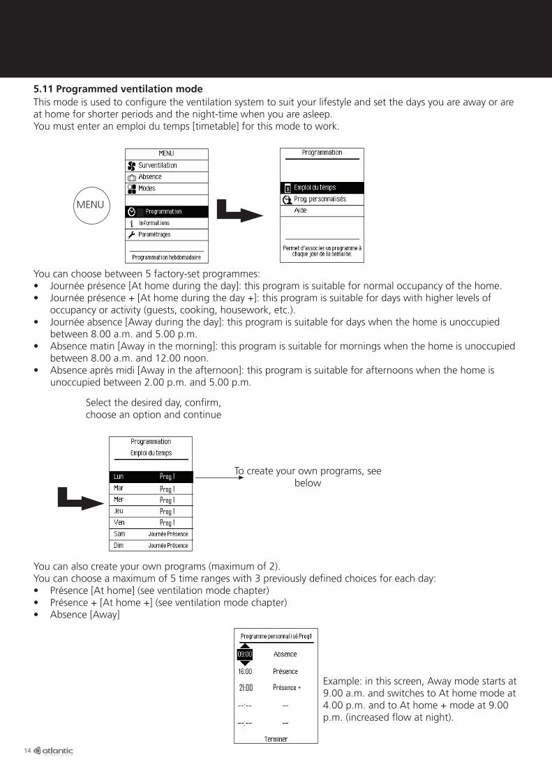
5.11 Programmed ventilation modeThis mode is used to configure the ventilation system to suit your lifestyle and set the days you are away or are at home for shorter periods and the night-time when you are asleep.You must enter an emploi du temps [timetable] for this mode to work.
You can choose between 5 factory-set programmes:• Journée présence [At home during the day]: this program is suitable for normal occupancy of the home.• Journée présence + [At home during the day +]: this program is suitable for days with higher levels of
occupancy or activity (guests, cooking, housework, etc.).• Journée absence [Away during the day]: this program is suitable for days when the home is unoccupied
between 8.00 a.m. and 5.00 p.m.• Absence matin [Away in the morning]: this program is suitable for mornings when the home is unoccupied
between 8.00 a.m. and 12.00 noon.• Absence après midi [Away in the afternoon]: this program is suitable for afternoons when the home is
unoccupied between 2.00 p.m. and 5.00 p.m.
You can also create your own programs (maximum of 2).You can choose a maximum of 5 time ranges with 3 previously defined choices for each day:• Présence [At home] (see ventilation mode chapter)• Présence + [At home +] (see ventilation mode chapter)• Absence [Away]
Example: in this screen, Away mode starts at 9.00 a.m. and switches to At home mode at 4.00 p.m. and to At home + mode at 9.00 p.m. (increased flow at night).
Select the desired day, confirm, choose an option and continue
To create your own programs, see below
Prog 1Prog 1
Prog 1Prog 1
Prog 1
21:00 Présence +
MENU
15
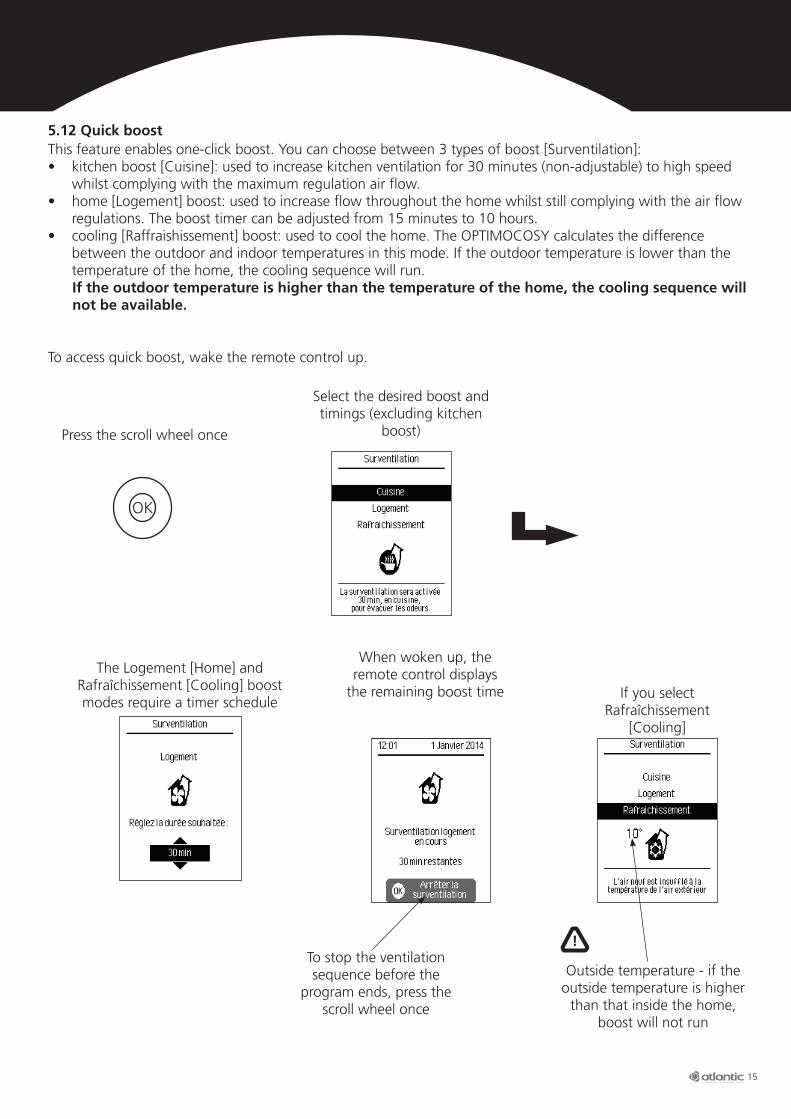
To access quick boost, wake the remote control up.
Press the scroll wheel once
Select the desired boost and timings (excluding kitchen
boost)
This feature enables one-click boost. You can choose between 3 types of boost [Surventilation]:• kitchen boost [Cuisine]: used to increase kitchen ventilation for 30 minutes (non-adjustable) to high speed
whilst complying with the maximum regulation air flow.• home [Logement] boost: used to increase flow throughout the home whilst still complying with the air flow
regulations. The boost timer can be adjusted from 15 minutes to 10 hours.• cooling [Raffraishissement] boost: used to cool the home. The OPTIMOCOSY calculates the difference
between the outdoor and indoor temperatures in this mode. If the outdoor temperature is lower than the temperature of the home, the cooling sequence will run.
If the outdoor temperature is higher than the temperature of the home, the cooling sequence will not be available.
5.12 Quick boost
OK
Outside temperature - if the outside temperature is higher
than that inside the home, boost will not run
To stop the ventilation sequence before the
program ends, press the scroll wheel once
If you select Rafraîchissement
[Cooling]
When woken up, the remote control displays
the remaining boost time
The Logement [Home] and Rafraîchissement [Cooling] boost modes require a timer schedule
!
16
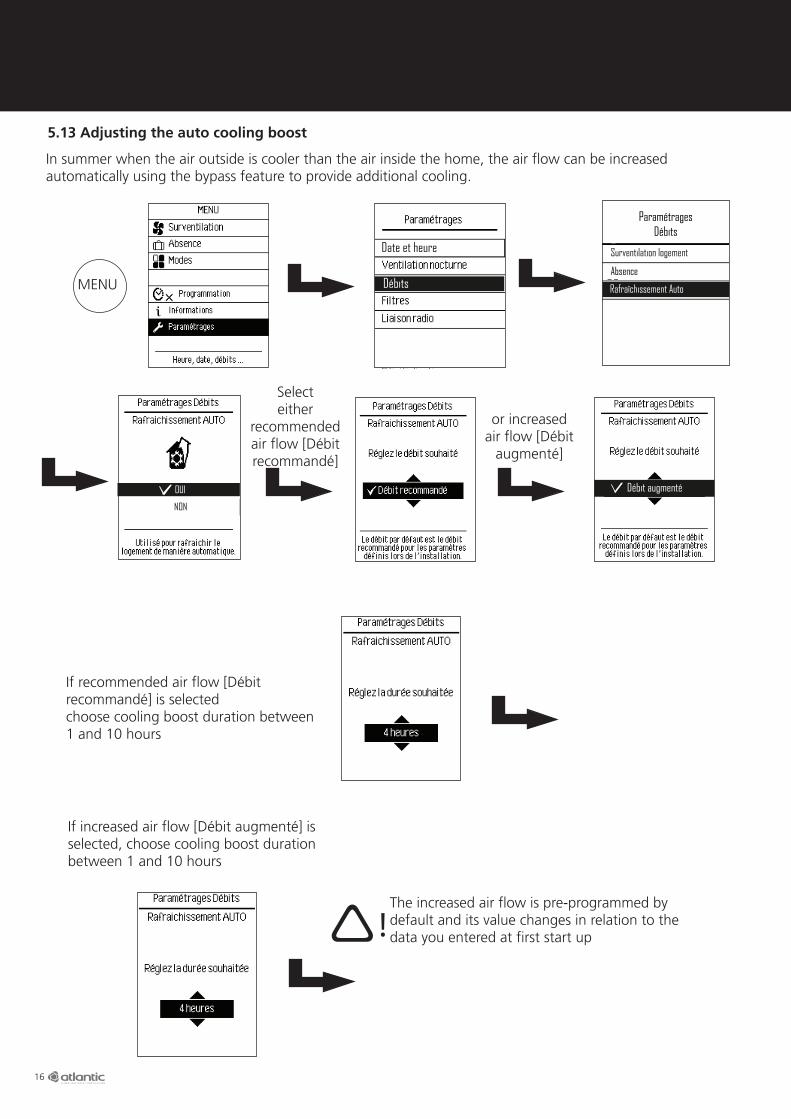
5.13 Adjusting the auto cooling boost
Select either
recommendedair flow [Débit recommandé]
or increased air flow [Débit
augmenté]
In summer when the air outside is cooler than the air inside the home, the air flow can be increased automatically using the bypass feature to provide additional cooling.
Débits
Date et heure
ParamétragesDébits
Surventilation logement
Absence
Rafraîchissement Auto
OUI
NON
Débit augmenté
If recommended air flow [Débit recommandé] is selectedchoose cooling boost duration between 1 and 10 hours
If increased air flow [Débit augmenté] is selected, choose cooling boost duration between 1 and 10 hours
The increased air flow is pre-programmed by default and its value changes in relation to the data you entered at first start up!
MENU

17
5.14. Controlling the OPTIMOCOSY according to CO2 level
5.15. Qualité d’air et confort [Air quality and comfort level]
The OPTIMOCOSY controls the air flow according to the CO2 level: the lower the CO2 level, the lower the air flow as less air needs to be changed and the higher the CO2 level, the higher the air flow as more air needs to be changed.
Modes
Paramétrages
MENU
The air quality (CO2 level) and comfort (temperature) logs can be viewed at any time
Air quality (CO2 level) data
Real time temperature data Maximum and minimum temperatures reached data
MENU
8°C
20°C18°C
10°C
8°C
18
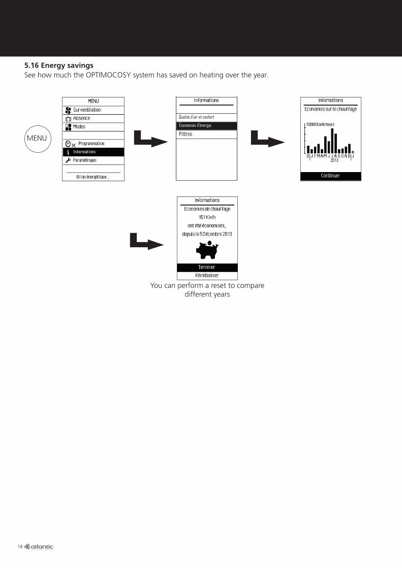
See how much the OPTIMOCOSY system has saved on heating over the year.
You can perform a reset to compare different years
5.16 Energy savings
Qualité d’air et confort
Economies d’énergie
MENU
19
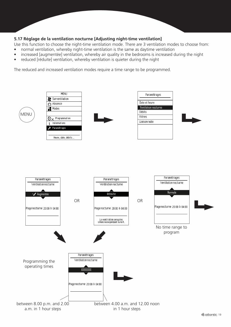
5.17 Réglage de la ventilation nocturne [Adjusting night-time ventilation]Use this function to choose the night-time ventilation mode. There are 3 ventilation modes to choose from:• normal ventilation, whereby night-time ventilation is the same as daytime ventilation• increased [augmentée] ventilation, whereby air quality in the bedrooms is increased during the night• reduced [réduite] ventilation, whereby ventilation is quieter during the night
The reduced and increased ventilation modes require a time range to be programmed.
OR OR
No time range to program
Programming the operating times
between 8.00 p.m. and 2.00 a.m. in 1 hour steps
between 4.00 a.m. and 12.00 noon in 1 hour steps
Ventilation nocturneDate et heure
Augmentée Normale
XXXXXXXX
MENU
20
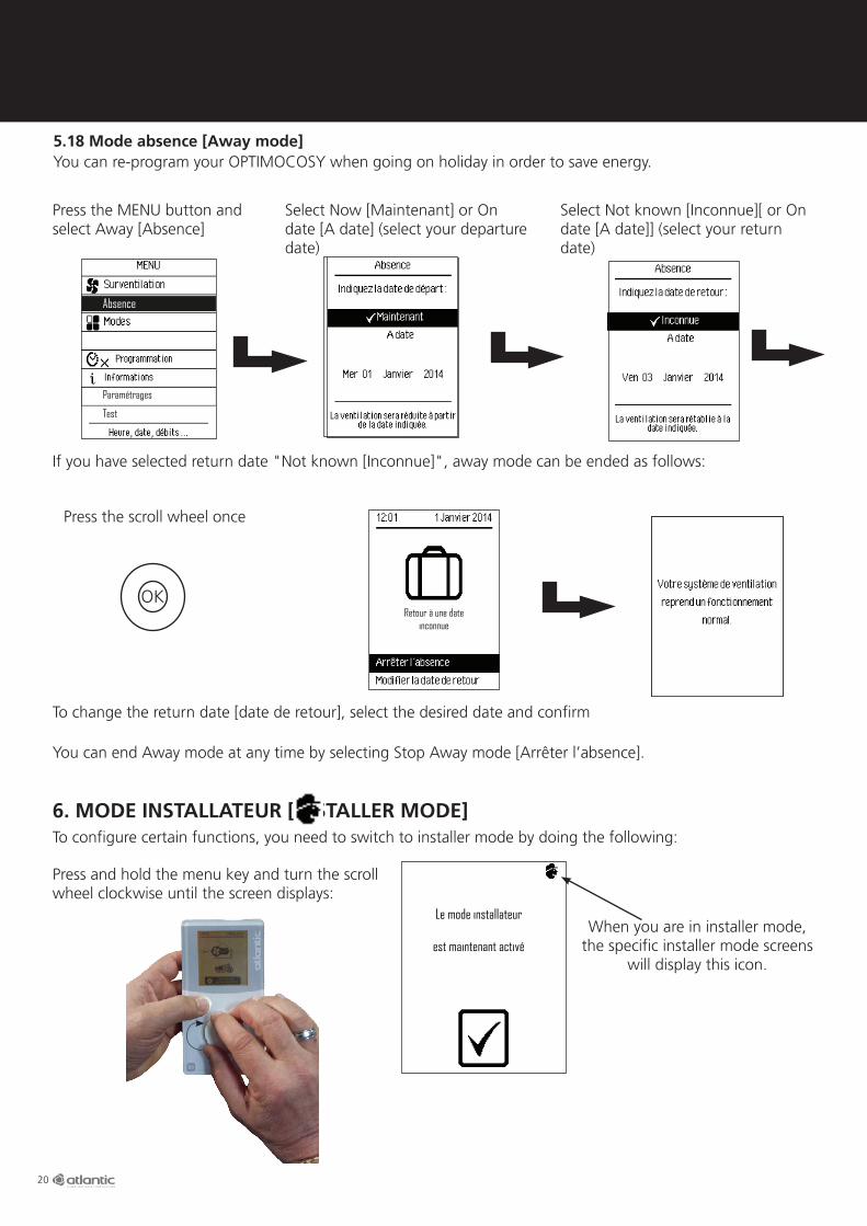
Press the MENU button and select Away [Absence]
Select Now [Maintenant] or On date [A date] (select your departure date)
Select Not known [Inconnue][ or On date [A date]] (select your return date)
You can re-program your OPTIMOCOSY when going on holiday in order to save energy. 5.18 Mode absence [Away mode]
Test
Absence
Paramétrages
Bat. élec. antigivrage
If you have selected return date "Not known [Inconnue]", away mode can be ended as follows:
To change the return date [date de retour], select the desired date and confirm
Press the scroll wheel once
You can end Away mode at any time by selecting Stop Away mode [Arrêter l’absence].
OKRetour à une date
inconnue
6. MODE INSTALLATEUR [INSTALLER MODE]To configure certain functions, you need to switch to installer mode by doing the following:
Press and hold the menu key and turn the scroll wheel clockwise until the screen displays:
When you are in installer mode, the specific installer mode screens
will display this icon.
Le mode installateur
est maintenant activé
Le mode installateur
est maintenant activé

21
To stop controlling the motor, press Terminer [End].
Le mode installateur
est maintenant activé
Le mode installateur
est maintenant activé
6.2 Testing the installation
6.1 Resetting the start-up sequence
Once the settings OPTIMOCOSY needs to operate have been entered, you can test your installation.
In this mode OPTIMOCOSY stops operating and you can control the components one at a time.
Switch to installer mode
Switch to installer mode
Press the MENU button and select Test
Test
Paramétrages
Bat. élec. antigivrage
Select Extractor Motor [Moteur Extraction]
Extractor Motor example; the procedure is the same for the other components
If you want to restart the sequence after making a mistake.
MENU
MENU
TestRéinitialisation
Date et Heure
Réinitialiser
Abandonner

22
6.3 Réglage du déséquilibre [Adjusting the imbalance]
In dual flow networks, blown air flow must equal extracted air flow. However, in certain networks, this balance cannot achieved (due to leaks, elbows and/or load losses). To remedy this situation, an imbalance must be created between the fresh air and extracted air flows.Begin by carrying out a survey of the air flows in the house: blown air (living areas) and extracted air (bathrooms/toilets and kitchen). For example, if the extracted air flow is 160 m3/h and the blown air flow is 170 m3/h, a + 10 m3/h imbalance is needed to balance the networks.
Test
Select the desired positive or negative imbalance [déséquilibre] value in m3/h
The adjustment range is +50 to -50 m3/h in 5 m3/hsteps
Débits
Date et Heure
Switch to installer mode
Switch to installer mode
ParamétragesDébits
Surventilation logement
Absence
Rafraîchissement Auto
Présence
Surventilation cuisine
Déséquilibre
Réinitialisation des débits
6.4 Réglage du débit d’absence [Adjusting the away air flow]
Test
The air flow can be adjusted from 47 m3/h to 299 m3/h in 3 m3/h steps (the default value will depend on your
home)
Débits
Date et Heure
ParamétragesDébits
Surventilation logement
Absence
Rafraîchissement Auto
Présence
Surventilation cuisine
Déséquilibre
Réinitialisation des débits
Débits
Date et Heure
MENU
47
Le mode installateur
est maintenant activé
Le mode installateur
est maintenant activé
MENU
23
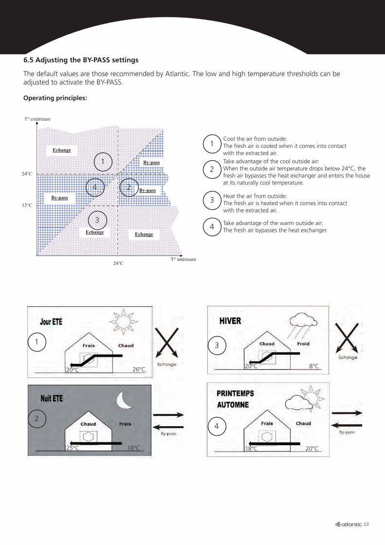
The default values are those recommended by Atlantic. The low and high temperature thresholds can be adjusted to activate the BY-PASS.
6.5 Adjusting the BY-PASS settings
Operating principles:
1
2
3
4
24°C
24°C
12°C
T° intérieure
T° extérieure
Echange
Echange Echange
By-pass
By-passBy-pass
1
2
3
4
Cool the air from outside:The fresh air is cooled when it comes into contact with the extracted air.
Heat the air from outside:The fresh air is heated when it comes into contact with the extracted air.
Take advantage of the cool outside air:Whentheoutsideairtemperaturedropsbelow24°C,thefresh air bypasses the heat exchanger and enters the house at its naturally cool temperature.
Take advantage of the warm outside air: The fresh air bypasses the heat exchanger.
Principe :
Equilibrage réseau d’insufflation : Une fois le réseau installé, il est nécessaire de régler les bouches d’insufflation (air neuf), le débit doit être équiréparti dans toutes les pièces. Pour cela ouvrir toutes les bouches du réseau. Commencer par la bouche la plus éloignée de la centrale, vérifier qu’il y a un débit minimum. Ensuite passer à la suivante, la fermer de quelques tours puis répéter l’opération sur toutes les bouches d’insufflation en les fermant de plus en plus au fur et à mesure que l’on se rapproche de la centrale.
1
2
26°C20°C
25°C 18°C
Principe :
Equilibrage réseau d’insufflation : Une fois le réseau installé, il est nécessaire de régler les bouches d’insufflation (air neuf), le débit doit être équiréparti dans toutes les pièces. Pour cela ouvrir toutes les bouches du réseau. Commencer par la bouche la plus éloignée de la centrale, vérifier qu’il y a un débit minimum. Ensuite passer à la suivante, la fermer de quelques tours puis répéter l’opération sur toutes les bouches d’insufflation en les fermant de plus en plus au fur et à mesure que l’on se rapproche de la centrale.
3
4
20°C
18°C 20°C
8°C

24
L N
3 2 1
MEarth-to-air heat exchanger
servomotor
Outside temperature
probe
6.6 Earth-to-air heat exchanger wiring and settings
Earth-to-air heat exchangers use underground thermal inertia to heat fresh air in winter and cool it in summer. The unit connects to the OPTIMOCOSY's fresh air intake [entrée d'air neuf].Setting the earth-to-air heat exchanger thresholds: The fresh air entering the OPTIMOCOSY first passes through the earth-to-air heat exchanger which consists of a buried pipe. This heats the air in winter and thereby increases the efficiency of the system. In summer, the system provides natural and free cooling 24 hours a day.During periods of warm weather, the OPTIMOCOSY can blow fresh air directly into the home by bypassing the heat exchanger but still pass it through the filter. When the fresh air passes through an earth-to-air heat exchanger, it is cooled naturally before entering the home.
When you start your OPTIMOCOSY for the first time, you will be asked to enter your home configuration settings. To configure the earth-to-air heat exchanger settings, go through the following steps:
Low temperature: outside temperature below which the earth-to-air heat exchanger is enabled (in winter) to take advantage of the underground heat.
High temperature: outside temperature above which the earth-to-air heat exchanger is enabled (in summer) to take advantage of the underground cold.
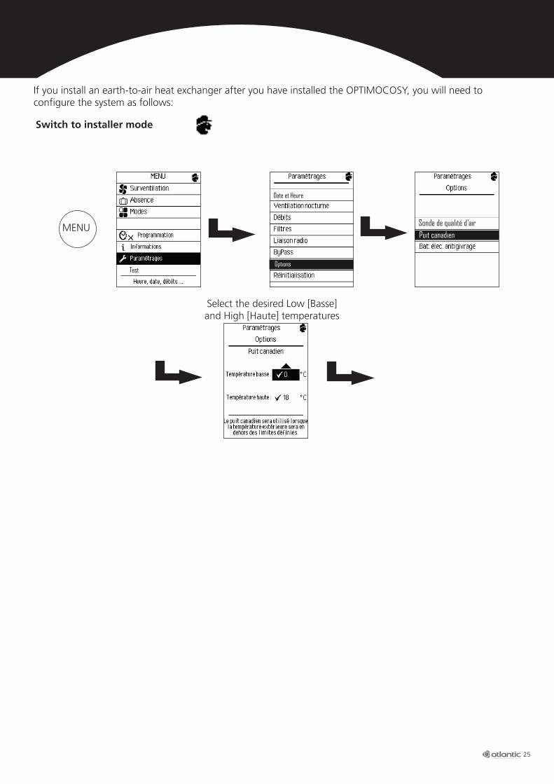
Select the desired Low [Basse] and High [Haute] temperatures
OUI27
5
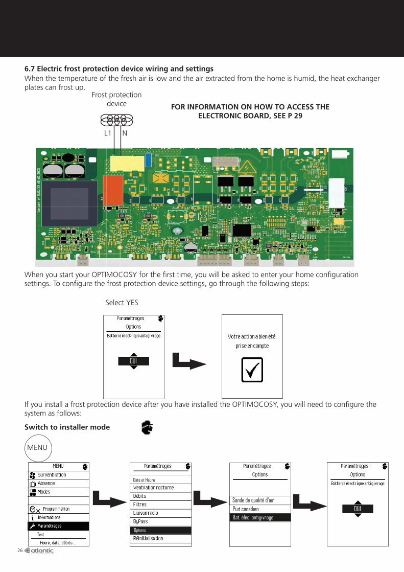
FOR INFORMATION ON HOW TO ACCESS THE ELECTRONIC BOARD, SEE P 29
25
If you install an earth-to-air heat exchanger after you have installed the OPTIMOCOSY, you will need to configure the system as follows:
Switch to installer mode
Test
Select the desired Low [Basse] and High [Haute] temperatures
Options
Date et Heure
Puit canadienSonde de qualité d’airMENU
Le mode installateur
est maintenant activé
26
If you install a frost protection device after you have installed the OPTIMOCOSY, you will need to configure the system as follows:
Puit canadienBat. élec. antigivrage
Sonde de qualité d’airOUI
TestOptions
Date et Heure
6.7 Electric frost protection device wiring and settingsWhen the temperature of the fresh air is low and the air extracted from the home is humid, the heat exchanger plates can frost up.
Frost protection device
L1 N
When you start your OPTIMOCOSY for the first time, you will be asked to enter your home configuration settings. To configure the frost protection device settings, go through the following steps:
OUI
Select YES
MENU
Switch to installer mode
Le mode installateur
est maintenant activé
FOR INFORMATION ON HOW TO ACCESS THE ELECTRONIC BOARD, SEE P 29

27
We recommend that you change the filters once a year
7. SERVICING7.1. Changing the filtersThe filters should be changed by the person responsible for servicing the installation. The filters must be changed when the "warning" message is displayed on the remote control.
The filters can be purchased directly from your installer or from online shops including www.boutique-atlantic.fr (Filters for OPTIMOCOSY). The shop can be accessed directly by scanning the following code:
Warning on the remote control
To change the filters, see the diagram below: Remove the 3 filters
Remove the filter access panel
G4 fresh air intake pre-filter
G4 stale air intake filter
F7 fresh air intake filter
28
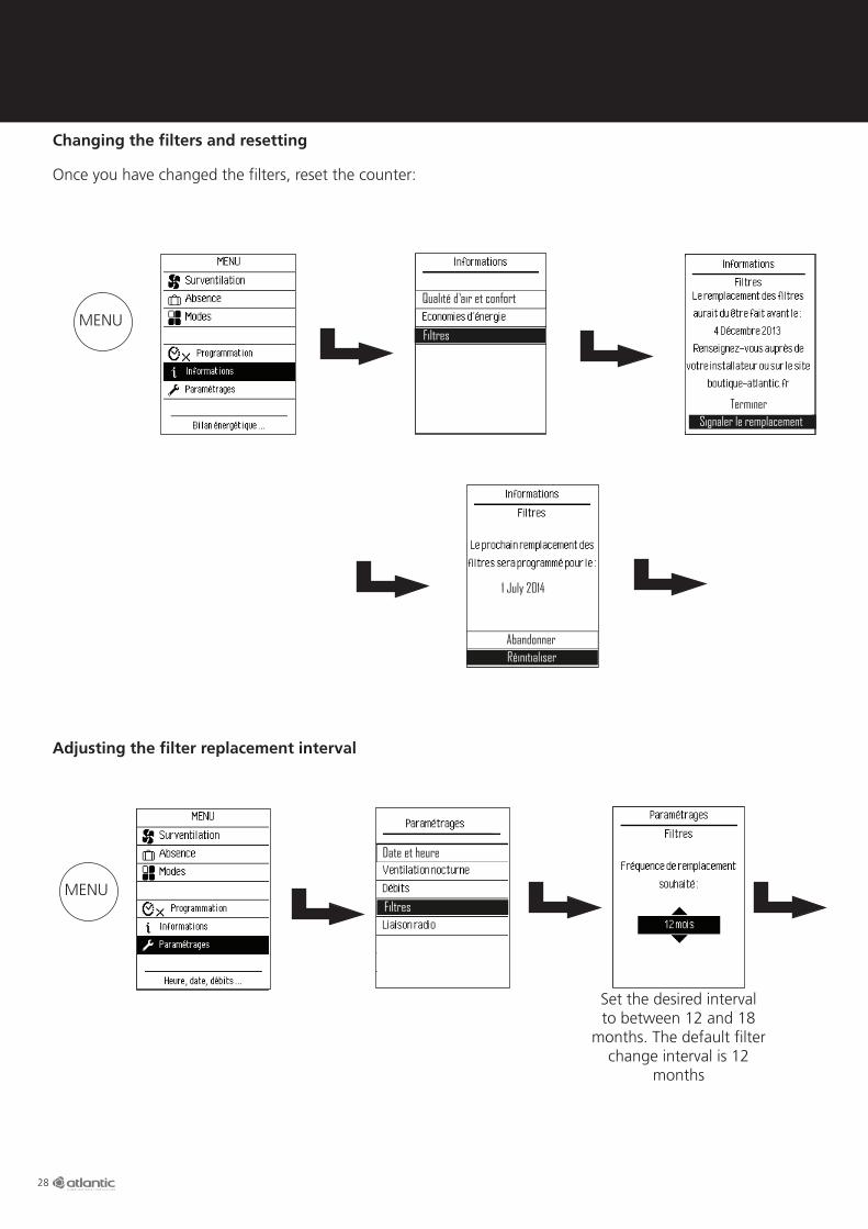
Changing the filters and resetting
Adjusting the filter replacement interval
Once you have changed the filters, reset the counter:
Filtres
Qualité d’air et confort
Signaler le remplacementTerminer
RéinitialiserAbandonner
1 July 2014
Filtres
MENU
Set the desired interval to between 12 and 18
months. The default filter change interval is 12
months
Filtres
Date et heure
MENU
29
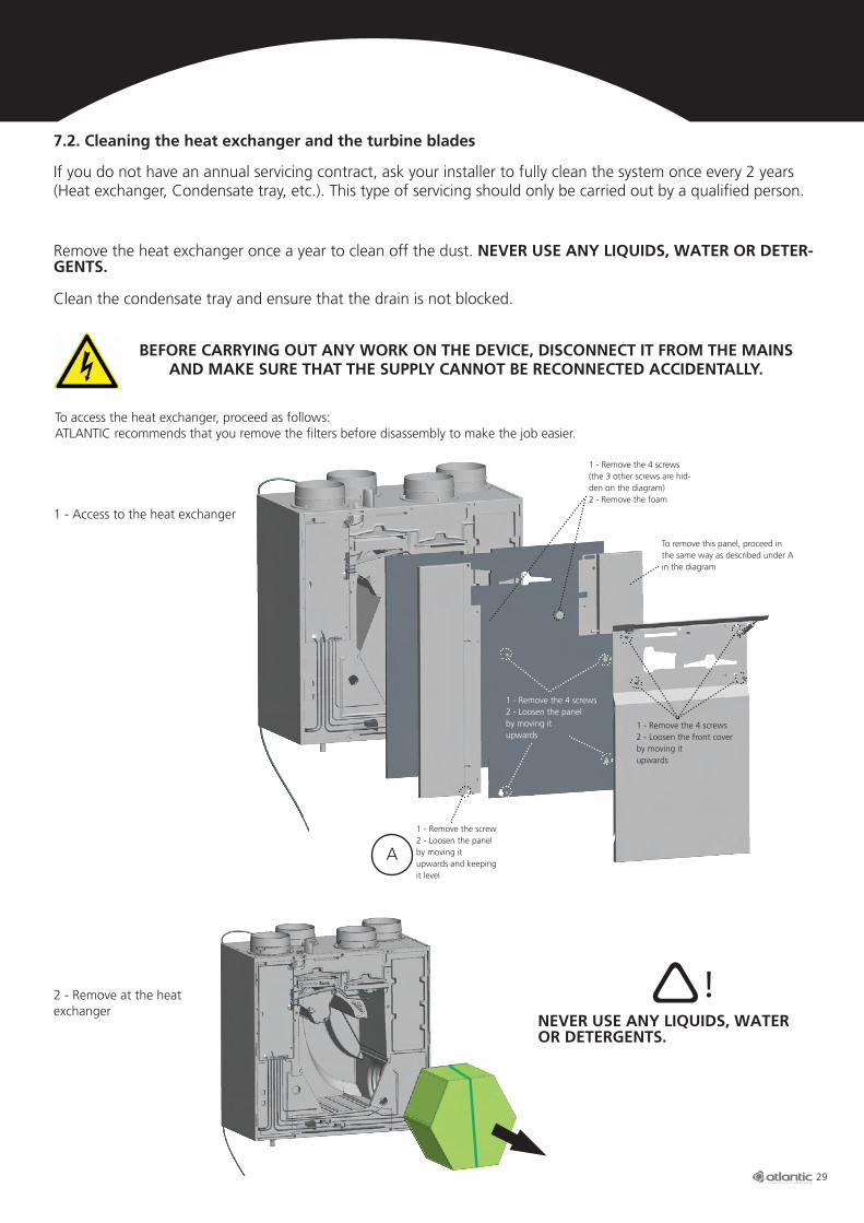
7.2. Cleaning the heat exchanger and the turbine blades
If you do not have an annual servicing contract, ask your installer to fully clean the system once every 2 years (Heat exchanger, Condensate tray, etc.). This type of servicing should only be carried out by a qualified person.
Remove the heat exchanger once a year to clean off the dust. NEVER USE ANY LIQUIDS, WATER OR DETER-GENTS.
Clean the condensate tray and ensure that the drain is not blocked.
BEFORE CARRYING OUT ANY WORK ON THE DEVICE, DISCONNECT IT FROM THE MAINS AND MAKE SURE THAT THE SUPPLY CANNOT BE RECONNECTED ACCIDENTALLY.
To access the heat exchanger, proceed as follows:ATLANTIC recommends that you remove the filters before disassembly to make the job easier.
1 - Access to the heat exchanger
2 - Remove at the heat exchanger
1 - Remove the 4 screws2 - Loosen the front cover by moving it upwards
1 - Remove the 4 screws (the 3 other screws are hid-den on the diagram)2 - Remove the foam
1 - Remove the screw2 - Loosen the panel by moving it upwards and keeping it level
To remove this panel, proceed in the same way as described under A in the diagram
1 - Remove the 4 screws2 - Loosen the panel by moving it upwards
A
NEVER USE ANY LIQUIDS, WATER OR DETERGENTS.
!

30
8 BREAKDOWNS AND FAULTS
3 - Cleaning the turbine blades
Left-hand side Right-hand side
The turbine blades can be accessed when the heat exchanger is removed. Use a paint brush or air duster to clean the turbine blades.
If the signal is lost, move the remote control closer to the OPTIMOCOSY to re-establish the connection.If the remote control becomes unpaired from the OPTIMOCOSY, it must be re-paired in the following way:
Stay on this screen and leave the remote control close by
Liaison radio
Date et heure
XMENU
31
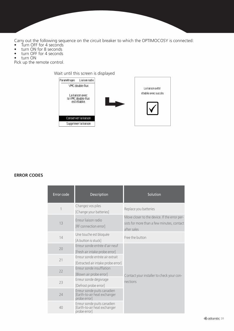
Wait until this screen is displayed
Carry out the following sequence on the circuit breaker to which the OPTIMOCOSY is connected:• Turn OFF for 4 seconds• turn ON for 8 seconds• turn OFF for 4 seconds• turn ON Pick up the remote control.
Error code Description Solution
1Changez vos piles
[Change your batteries]Replace you batteries
13Erreur liaison radio
[RF connection error]
Move closer to the device. If the error per-
sists for more than a few minutes, contact
after sales
14Une touche est bloquée
[A button is stuck]Free the button
20Erreur sonde entrée d’air neuf
[Fresh air intake probe error]
Contact your installer to check your con-
nections
21Erreur sonde entrée air extrait
[Extracted air intake probe error]
22Erreur sonde insufflation
[Blown air probe error]
23Erreur sonde dégivrage
[Defrost probe error]
24Erreur sonde puits canadien [Earth-to-air heat exchanger probe error]
40Erreur sonde puits canadien [Earth-to-air heat exchanger probe error]
ERROR CODES

© -
Pho
tos
for
info
rmat
ion
only
- 0
510
- A
tlant
ic C
limat
isat
ion
et V
entil
atio
n- 1
3, b
d M
onge
- 6
9330
Mey
zieu
- S
.A.S
. with
sha
re c
apita
l of
€2,9
16,4
00 -
RC
S Ly
on B
421
370
289
Head Office: Atlantic Climatisation et Ventilation
13, Bd Monge - ZI - BP 71 - 69882 Meyzieu CedexTel. +33 4 72 45 19 45www.atlantic-pro.fr
Installer's stamp:
9. WARRANTY
This device is guaranteed against all manufacturing defects for two years from the date of purchase. ATLANTIC Climatisation et Ventilation will therefore either exchange or supply those parts acknowledged to be faulty by its after sales team. Under no circumstances does the guarantee cover ancillary costs, be they labour, travelling expenses or other form of compensation of any sort. The guarantee specifically excludes damage due to the system not having been installed in accordance with this guide, improper use or repair attempts by unauthorised personnel. In case of problems, please contact your installer or, failing that, your retailer.
10. PROTECTING THE ENVIRONMENT
Treatment of waste electrical and electronic devices (applies to member countries of the European Union and other countries with selective collection systems).This logo indicates that the product must not be processed as domestic waste. It must be taken to an appropriate collection point for recycling electrical and electronic equipment. To find out more about recycling this product, please contact your local council, recycling centre or the shop you bought the product from.