fitness legacy zone rower - wicksteed.co.uk · specification installation instructions note note...
TRANSCRIPT
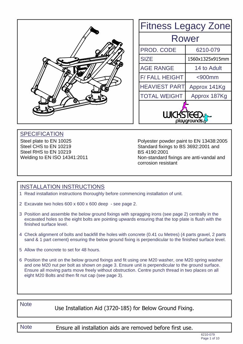
SPECIFICATION
INSTALLATION INSTRUCTIONS
Note
Note
PROD. CODE
SIZE
AGE RANGE
F/ FALL HEIGHT
HEAVIEST PART
TOTAL WEIGHT
Fitness Legacy Zone
Rower6210-079
14 to Adult
<900mm
Approx 141Kg
Approx 187Kg
6210-079Page 1 of 10
1560x1325x915mm
Ensure all installation aids are removed before first use.
Use Installation Aid (3720-185) for Below Ground Fixing.
Steel plate to EN 10025Steel CHS to EN 10219Steel RHS to EN 10219Welding to EN ISO 14341:2011
Polyester powder paint to EN 13438:2005Standard fixings to BS 3692:2001 andBS 4190:2001Non-standard fixings are anti-vandal andcorrosion resistant
1 Read installation instructions thoroughly before commencing installation of unit.
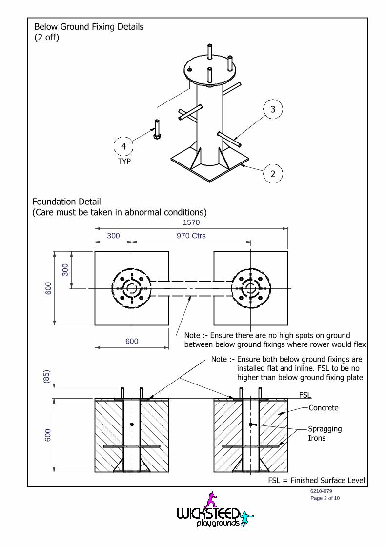
2 Excavate two holes 600 x 600 x 600 deep - see page 2.
3 Position and assemble the below ground fixings with spragging irons (see page 2) centrally in theexcavated holes so the eight bolts are pointing upwards ensuring that the top plate is flush with thefinished surface level.
4 Check alignment of bolts and backfill the holes with concrete (0.41 cu Metres) (4 parts gravel, 2 partssand & 1 part cement) ensuring the below ground fixing is perpendicular to the finished surface level.
5 Allow the concrete to set for 48 hours.
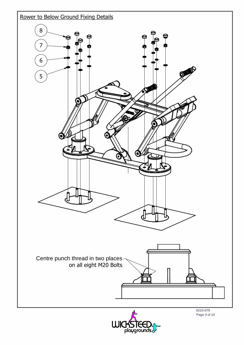
6 Position the unit on the below ground fixings and fit using one M20 washer, one M20 spring washerand one M20 nut per bolt as shown on page 3. Ensure unit is perpendicular to the ground surface.Ensure all moving parts move freely without obstruction. Centre punch thread in two places on alleight M20 Bolts and then fit nut cap (see page 3).
6210-079
Page 2 of 10
FSL = Finished Surface Level
Below Ground Fixing Details(2 off)
Foundation Detail(Care must be taken in abnormal conditions)
TYP
FSL
60
0
30
0
1570
970 Ctrs300
600
600
(85
)
Concrete
SpraggingIrons
Note :- Ensure there are no high spots on groundbetween below ground fixings where rower would flex
Note :- Ensure both below ground fixings areinstalled flat and inline. FSL to be nohigher than below ground fixing plate
3
2
4
6210-079
Page 3 of 10
Rower to Below Ground Fixing Details
Centre punch thread in two placeson all eight M20 Bolts
8
7
6
5
6210-079
Page 4 of 10
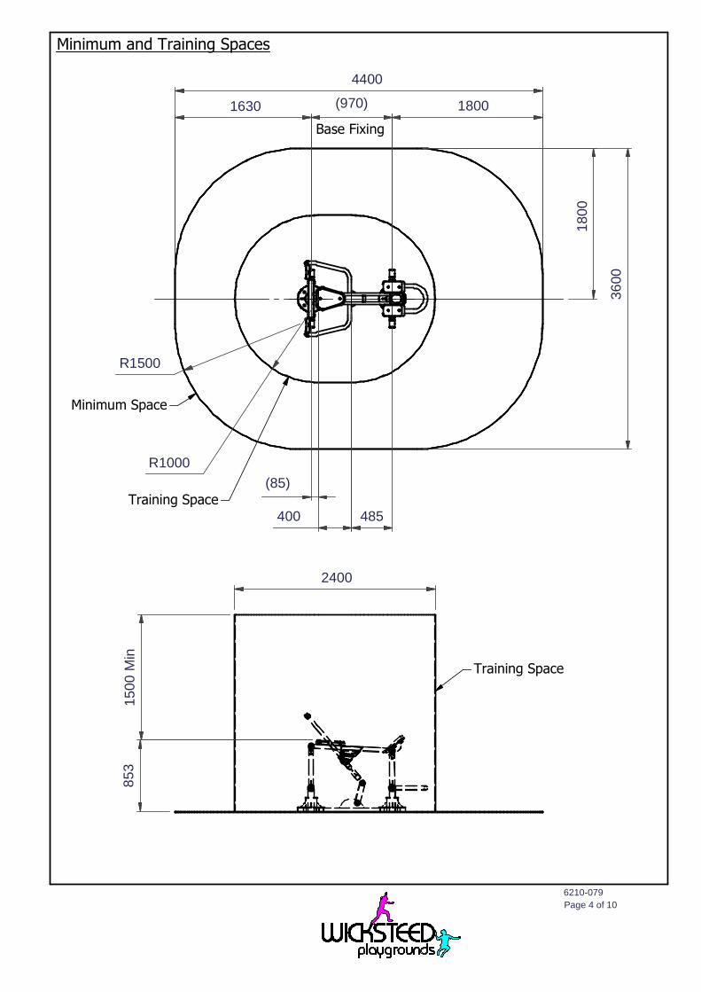
Minimum and Training Spaces
150
0M
in8
53
Training Space
(970)1630
36
00
(85)
485
R1000
400Training Space
Minimum Space
2400
4400
Base Fixing
180
0
1800
R1500
6210-079
Page 5 of 10
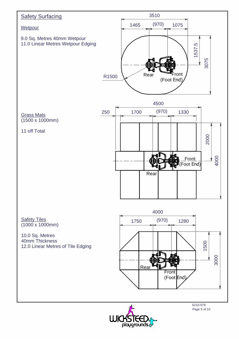
Safety Surfacing
Wetpour
9.0 Sq. Metres 40mm Wetpour11.0 Linear Metres Wetpour Edging
Grass Mats(1500 x 1000mm)
11 off Total
Safety Tiles(1000 x 1000mm)
10.0 Sq. Metres40mm Thickness12.0 Linear Metres of Tile Edging
3510
30
75
1537
.5
(970)1465 1075
Front(Foot End)
RearR1500
4500
1700 (970) 1330
20
00
40
00
Rear
Front(Foot End)
300
0
15
00
(970)1750 1280
4000
RearFront(Foot End)
250
6210-079
Page 6 of 10
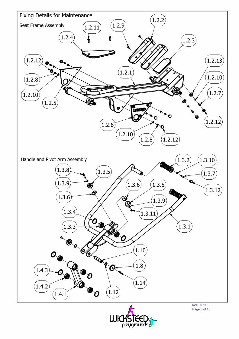
Fixing Details for Maintenance
Seat Frame Assembly
Handle and Pivot Arm Assembly
1.2.4
1.2.11 1.2.91.2.2
1.2.3
1.2.5
1.2.12
1.2.8
1.2.10
1.2.6
1.2.101.2.8 1.2.12
1.2.13
1.2.10
1.2.7
1.2.12
1.2.1
1.3.2 1.3.10
1.3.7
1.3.12
1.3.1
1.3.11
1.3.9
1.3.51.3.6
1.3.51.3.8
1.3.9
1.3.6
1.4.1
1.4.2
1.4.3
1.10
1.12
1.8
1.14
1.3.4
1.3.3
6210-079
Page 7 of 11
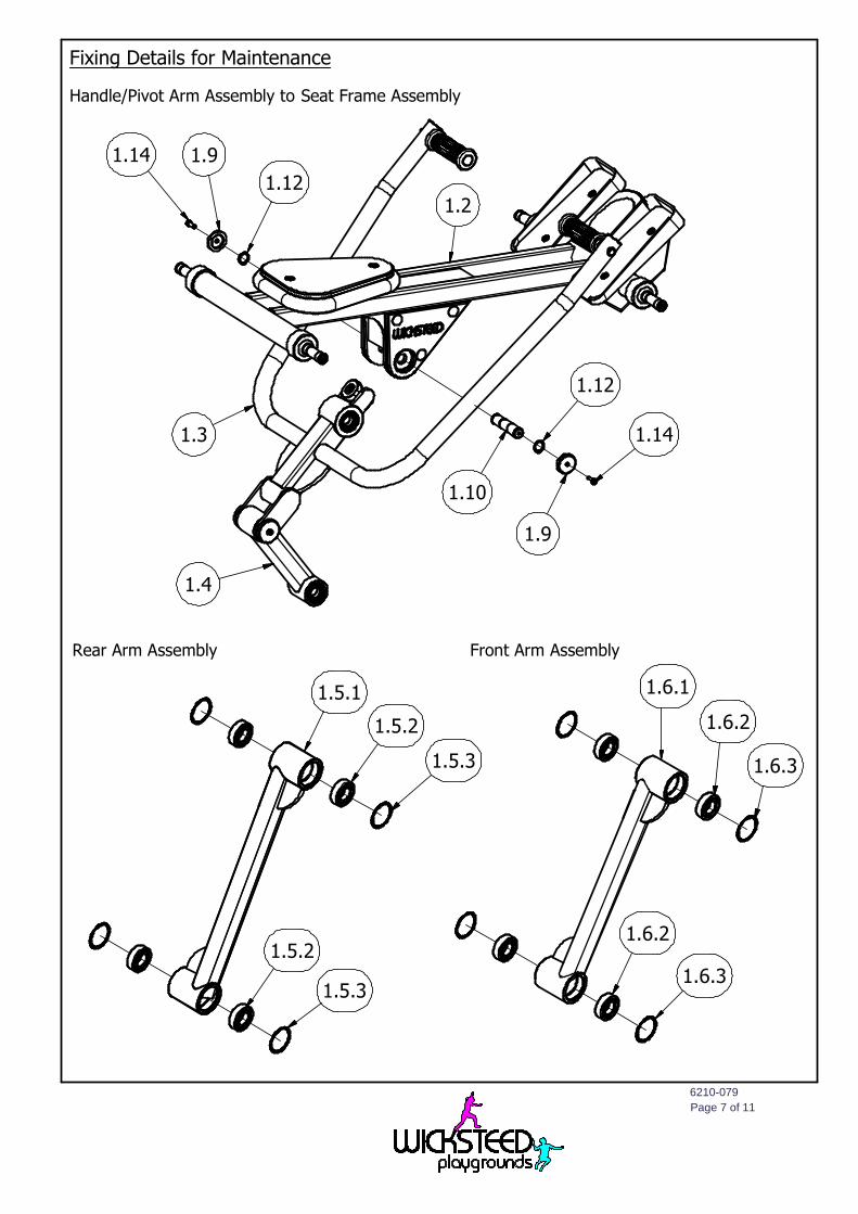
Fixing Details for Maintenance
Handle/Pivot Arm Assembly to Seat Frame Assembly
Rear Arm Assembly Front Arm Assembly
1.10
1.9
1.12
1.141.3
1.4
1.14 1.9
1.121.2
1.5.1
1.5.2
1.5.3
1.5.3
1.5.2
1.6.1
1.6.2
1.6.3
1.6.2
1.6.3
6210-079
Page 8 of 11
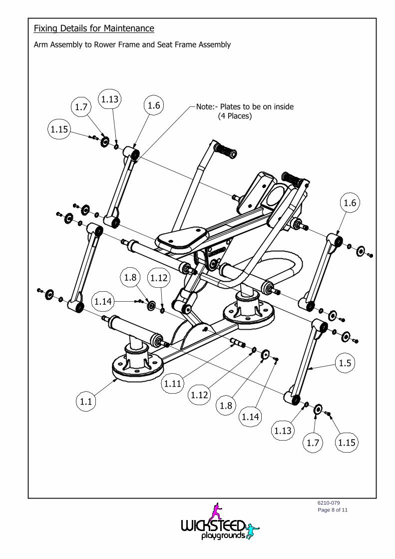
Fixing Details for Maintenance
Arm Assembly to Rower Frame and Seat Frame Assembly
1.6
1.5
1.11
1.121.8
1.14
1.13
1.7 1.15
1.1
1.14
1.8 1.12
1.15
1.71.13
1.6 Note:- Plates to be on inside(4 Places)
6210-079
Page 9 of 10
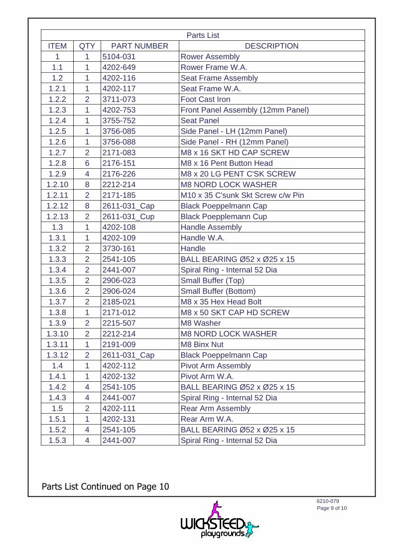
Parts List
ITEM QTY PART NUMBER DESCRIPTION
1 1 5104-031 Rower Assembly
1.1 1 4202-649 Rower Frame W.A.
1.2 1 4202-116 Seat Frame Assembly
1.2.1 1 4202-117 Seat Frame W.A.
1.2.2 2 3711-073 Foot Cast Iron
1.2.3 1 4202-753 Front Panel Assembly (12mm Panel)
1.2.4 1 3755-752 Seat Panel
1.2.5 1 3756-085 Side Panel - LH (12mm Panel)
1.2.6 1 3756-088 Side Panel - RH (12mm Panel)
1.2.7 2 2171-083 M8 x 16 SKT HD CAP SCREW
1.2.8 6 2176-151 M8 x 16 Pent Button Head
1.2.9 4 2176-226 M8 x 20 LG PENT C'SK SCREW
1.2.10 8 2212-214 M8 NORD LOCK WASHER
1.2.11 2 2171-185 M10 x 35 C'sunk Skt Screw c/w Pin
1.2.12 8 2611-031_Cap Black Poeppelmann Cap
1.2.13 2 2611-031_Cup Black Poepplemann Cup
1.3 1 4202-108 Handle Assembly
1.3.1 1 4202-109 Handle W.A.
1.3.2 2 3730-161 Handle
1.3.3 2 2541-105 BALL BEARING Ø52 x Ø25 x 15
1.3.4 2 2441-007 Spiral Ring - Internal 52 Dia
1.3.5 2 2906-023 Small Buffer (Top)
1.3.6 2 2906-024 Small Buffer (Bottom)
1.3.7 2 2185-021 M8 x 35 Hex Head Bolt
1.3.8 1 2171-012 M8 x 50 SKT CAP HD SCREW
1.3.9 2 2215-507 M8 Washer
1.3.10 2 2212-214 M8 NORD LOCK WASHER
1.3.11 1 2191-009 M8 Binx Nut
1.3.12 2 2611-031_Cap Black Poeppelmann Cap
1.4 1 4202-112 Pivot Arm Assembly
1.4.1 1 4202-132 Pivot Arm W.A.
1.4.2 4 2541-105 BALL BEARING Ø52 x Ø25 x 15
1.4.3 4 2441-007 Spiral Ring - Internal 52 Dia
1.5 2 4202-111 Rear Arm Assembly
1.5.1 1 4202-131 Rear Arm W.A.
1.5.2 4 2541-105 BALL BEARING Ø52 x Ø25 x 15
1.5.3 4 2441-007 Spiral Ring - Internal 52 Dia
Parts List Continued on Page 10
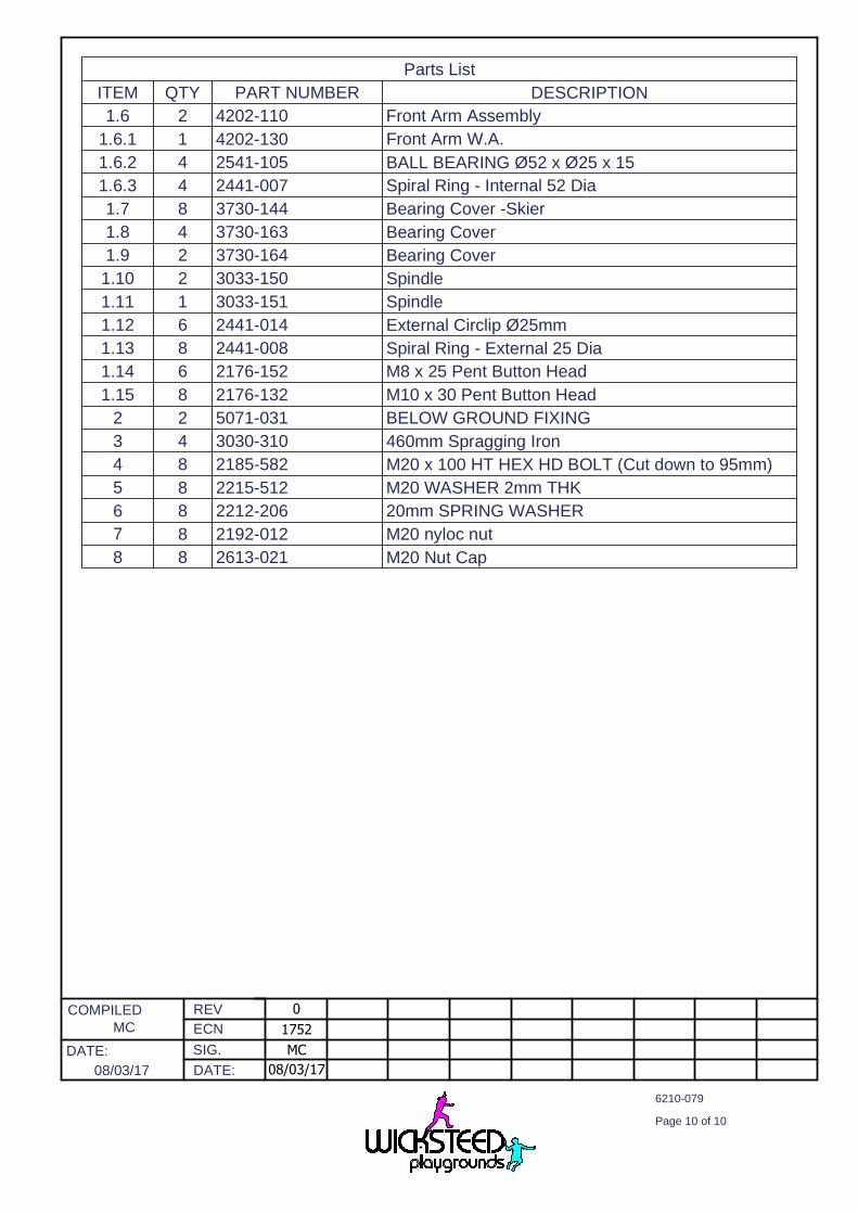
Parts List
ITEM QTY PART NUMBER DESCRIPTION
1.6 2 4202-110 Front Arm Assembly
1.6.1 1 4202-130 Front Arm W.A.
1.6.2 4 2541-105 BALL BEARING Ø52 x Ø25 x 15
1.6.3 4 2441-007 Spiral Ring - Internal 52 Dia
1.7 8 3730-144 Bearing Cover -Skier
1.8 4 3730-163 Bearing Cover
1.9 2 3730-164 Bearing Cover
1.10 2 3033-150 Spindle
1.11 1 3033-151 Spindle
1.12 6 2441-014 External Circlip Ø25mm
1.13 8 2441-008 Spiral Ring - External 25 Dia
1.14 6 2176-152 M8 x 25 Pent Button Head
1.15 8 2176-132 M10 x 30 Pent Button Head
2 2 5071-031 BELOW GROUND FIXING
3 4 3030-310 460mm Spragging Iron
4 8 2185-582 M20 x 100 HT HEX HD BOLT (Cut down to 95mm)
5 8 2215-512 M20 WASHER 2mm THK
6 8 2212-206 20mm SPRING WASHER
7 8 2192-012 M20 nyloc nut
8 8 2613-021 M20 Nut Cap
REV
ECN
SIG.
DATE:
COMPILED
DATE:
6210-079
Page 10 of 10
MC
08/03/17 08/03/17
MC
1752
0
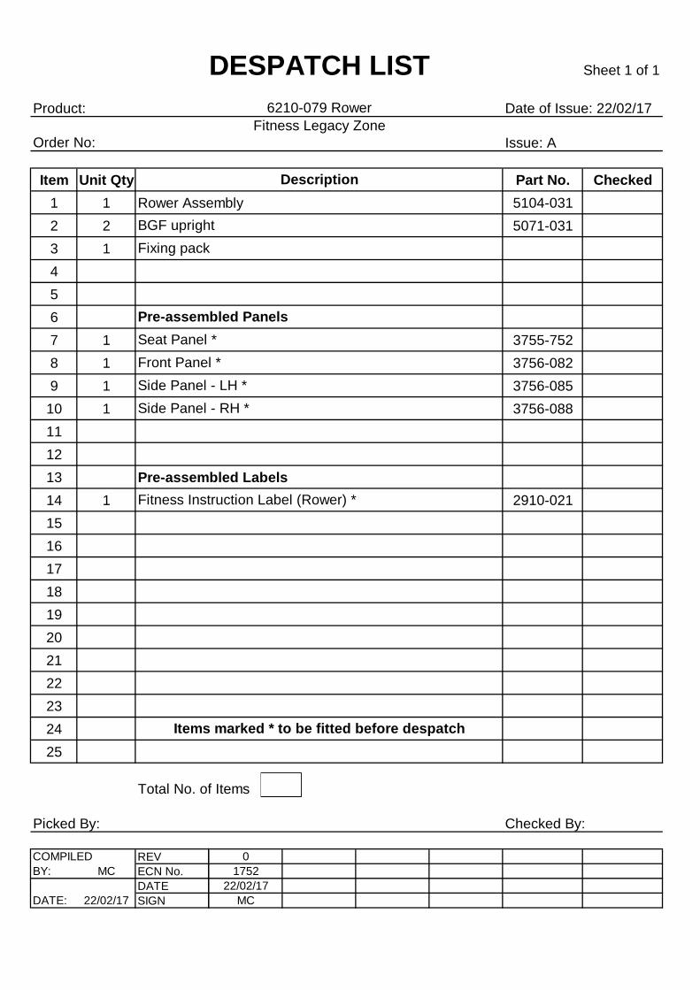
Product: Date of Issue: 22/02/17Fitness Legacy Zone
Issue: A
Item Unit Qty Part No. Checked
1 1 Rower Assembly 5104-031
2 2 5071-031
3 1
4
5
6
7 1 3755-752
8 1 3756-082
9 1 3756-085
10 1 3756-088
11
12
13 Pre-assembled Labels
14 1 2910-021
15
16
17
18
19
20
21
22
23
24
25
Picked By: Checked By:
COMPILED REV 0
BY: MC ECN No. 1752
DATE 22/02/17
DATE: 22/02/17 SIGN MC
Order No:
BGF upright
Pre-assembled Panels
Side Panel - LH *
Seat Panel *
Sheet 1 of 1
Front Panel *
DESPATCH LIST
Fitness Instruction Label (Rower) *
Side Panel - RH *
Fixing pack
6210-079 Rower
Description
Total No. of Items
Items marked * to be fitted before despatch
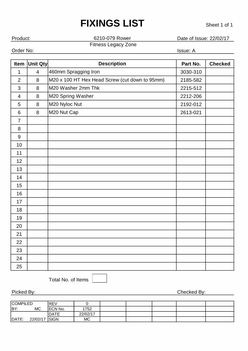
Product: Date of Issue: 22/02/17Fitness Legacy Zone
Issue: A
Item Unit Qty Part No. Checked
1 4 3030-310
2 8 2185-582
3 8 2215-512
4 8 2212-206
5 8 2192-012
6 8 2613-021
7
8
9
10
11
12
13
14
15
16
17
18
19
20
21
22
23
24
25
Picked By: Checked By:
COMPILED REV 0
BY: MC ECN No. 1752
DATE 22/02/17
DATE: 22/02/17 SIGN MC
Sheet 1 of 1
6210-079 Rower
M20 Nyloc Nut
M20 Nut Cap
Order No:
Description
460mm Spragging Iron
M20 x 100 HT Hex Head Screw (cut down to 95mm)
Total No. of Items
M20 Washer 2mm Thk
FIXINGS LIST
M20 Spring Washer