fit ultrasonico 1
TRANSCRIPT

8/10/2019 Fit Ultrasonico 1
http://slidepdf.com/reader/full/fit-ultrasonico-1 1/40
OPTISONIC 7300OPTISONIC 7300OPTISONIC 7300OPTISONIC 7300 Technical DatasheetTechnical DatasheetTechnical DatasheetTechnical Datasheet
Ultrasonic gas flowmeter
• Wide application range• No moving parts and no pressure loss• Complete solution for gasflow measurement
© KROHNE 04/2013 - 4001344704 - TD OPTISONIC 7300 R04 en

8/10/2019 Fit Ultrasonico 1
http://slidepdf.com/reader/full/fit-ultrasonico-1 2/40
CONTENTS
2 www.krohne.com 04/2013 - 4001344704 - TD OPTISONIC 7300 R04 en
OPTISONIC 7300
1 Product features 3
1.1 Ultrasonic process gas flow measurement..................................................................... 31.2 Variants............................................................................................................................. 51.3 Features............................................................................................................................ 61.4 Measuring principle.......................................................................................................... 7
2 Technical data 8
2.1 Technical data................................................................................................................... 82.2 Dimensions and weights ................................................................................................ 19
2.2.1 Gas flow sensor, carbon steel .............................................................................................. 202.2.2 Converter housing................................................................................................................. 232.2.3 Mounting plate, field housing ............................................................................................... 24
3 Installation 25
3.1 General notes on installation ......................................................................................... 253.2 Intended use ................................................................................................................... 253.3 Installation requirements signal converter................................................................... 253.4 Installation requirements sensor .................................................................................. 25
3.4.1 Inlet and outlet...................................................................................................................... 263.4.2 Mounting position.................................................................................................................. 263.4.3 Flange deviation.................................................................................................................... 273.4.4 T-section ............................................................................................................................... 27
3.4.5 Vibration ................................................................................................................................ 283.4.6 Control valve ......................................................................................................................... 283.4.7 Insulation............................................................................................................................... 28
4 Electrical connections 29
4.1 Safety instructions.......................................................................................................... 294.2 Signal cable (remote versions only)............................................................................... 294.3 Power supply .................................................................................................................. 304.4 Inputs and outputs, overview ......................................................................................... 31
4.4.1 Combinations of the inputs/outputs (I/Os) ........................................................................... 31
4.4.2 Description of the CG number .............................................................................................. 324.4.3 Fixed, non-alterable input/output versions.......................................................................... 334.4.4 Alterable input/output versions............................................................................................ 34
5 Application form 35
6 Notes 37

8/10/2019 Fit Ultrasonico 1
http://slidepdf.com/reader/full/fit-ultrasonico-1 3/40
PRODUCT FEATURES1
3
OPTISONIC 7300
www.krohne.com04/2013 - 4001344704 - TD OPTISONIC 7300 R04 en
1.1 Ultrasonic process gas flow measurementThe OPTISONIC 7300OPTISONIC 7300OPTISONIC 7300OPTISONIC 7300 offers an ultrasonic measurement system dedicated for process gas flowapplications. The OPTISONIC 7300 does not have the limitations that are usually associated withtraditional gas flow meters like periodical recalibrations, maintenance, pressure loss and alimited flow range. The OPTISONIC 7300 combines the advantages of ultrasonic measurement ina way that it is efficient, reliable and easy to use.
1 Current input option for calculation to standard conditions2 Process connections

8/10/2019 Fit Ultrasonico 1
http://slidepdf.com/reader/full/fit-ultrasonico-1 4/40
1 PRODUCT FEATURES
4
OPTISONIC 7300
www.krohne.com 04/2013 - 4001344704 - TD OPTISONIC 7300 R04 en
Highlights• Wide flow range• Independent of gas density and composition to a large extend
• No maintenance• No recalibration• Integrated volume correction to standard conditions using P, T measurement• No moving parts, no pressure loss
Industries• Chemicals• Petrochemicals• Power plants• Oil & Gas
Applications• General process control• Hydrocarbon gases in petrochemical plants• Process gases in chemical plants• Production of natural gas• Consumption / usage of natural gas• Usage of fuel gas• Air flows• Biogas

8/10/2019 Fit Ultrasonico 1
http://slidepdf.com/reader/full/fit-ultrasonico-1 5/40
PRODUCT FEATURES1
5
OPTISONIC 7300
www.krohne.com04/2013 - 4001344704 - TD OPTISONIC 7300 R04 en
1.2 Variants
Version and some general examples
Version• Available as compact or remote versionConnection options• Standard flange range available up to
ASME 900 lb / PN 40. Others on request.Correction to standard conditions (optional)• Gas flow volume correction to standard conditions• Using temperature and pressure inputsGFC 300 ultrasonic signal converter• Compact or field housing: Ex / non-Ex, IP66/67

8/10/2019 Fit Ultrasonico 1
http://slidepdf.com/reader/full/fit-ultrasonico-1 6/40
1 PRODUCT FEATURES
6
OPTISONIC 7300
www.krohne.com 04/2013 - 4001344704 - TD OPTISONIC 7300 R04 en
1.3 Features
Transducer designTransducer designTransducer designTransducer design
With the innovative patented design of thetransducers, the OPTISONIC 7300 offers a superiorapplication range. This new design allows not only alarger flow and diameter range, but also anextended range of gases that can be measured.
Dedicated to process applicationsDedicated to process applicationsDedicated to process applicationsDedicated to process applicationsThe OPTISONIC 7300 combines the advantages ofultrasonic flow measurement (free of maintenance,no recalibrations, free of obstructions and no movingparts) with a design that is dedicated for the processindustry. For applications in the process industrythis combination offers the optimum value in bothoperational as in investment costs.
Calculation to standard conditionsCalculation to standard conditionsCalculation to standard conditionsCalculation to standard conditionsGas flow is often specified in standard conditions (forexample flow at 0 °C and 1 bar a). The gas flowconverter GFC 300 optionally has two current inputs.If these are used for pressure and temperatureinput, the converter can calculate the volume flow tostandard conditions. With the input of standarddensity also mass flow can be calculated.
DiagnosticsDiagnosticsDiagnosticsDiagnosticsImportant information about both the process andsensor can be provided by diagnostic values.Examples are gain for information about pollution inthe sensor, velocity of sound for changes in the gascomposition and signal to noise ratio for changes inthe process.
T = 100 C P = 100 Bar

8/10/2019 Fit Ultrasonico 1
http://slidepdf.com/reader/full/fit-ultrasonico-1 7/40
PRODUCT FEATURES1
7
OPTISONIC 7300
www.krohne.com04/2013 - 4001344704 - TD OPTISONIC 7300 R04 en
1.4 Measuring principle
• Like canoes crossing a river, acoustic signals are transmitted and received along a diagonalmeasuring path.
• A sound wave going downstream with the flow travels faster than a sound wave goingupstream against the flow.
• The difference in transit time is directly proportional to the mean flow velocity of the medium.
Figure 1-1: Measuring principle1 Sound wave against flow direction2 Sound wave with flow direction3 Flow direction

8/10/2019 Fit Ultrasonico 1
http://slidepdf.com/reader/full/fit-ultrasonico-1 8/40
2 TECHNICAL DATA
8
OPTISONIC 7300
www.krohne.com 04/2013 - 4001344704 - TD OPTISONIC 7300 R04 en
2.1 Technical data
• The following data is provided for general applications. If you require data that is morerelevant to your specific application, please contact us or your local sales office.
• Additional information (certificates, special tools, software,...) and complete productdocumentation can be downloaded free of charge from the website (Download Center).
Measuring systemMeasuring principle Ultrasonic transit timeApplication range Flow measurement of dry gasesMeasured valueMeasured valueMeasured valueMeasured valuePrimary measured value Transit timeSecondary measuredvalues
Volume flow, corrected volume flow, mass flow, molar mass, flow speed, flowdirection, speed of sound, gain, signal to noise ratio, reliability of flowmeasurement, quality of acoustic signal
DesignFeatures 1 or 2 path all welded flow sensor with o-ring fitted titanium transducers.Modular construction The measurement system consists of a measuring sensor and a signal
converter.Compact version OPTISONIC 7300 CRemote version OPTISONIC 7000 F with GFC 300 F signal converterNominal diameter 1 path: DN50...80 / 2...3"
2 path: DN100...600 / 4"...24"
Larger diameters on request.Measurement range -30... +30 m/s / -98.4... +98.4 ft/sSignal converterSignal converterSignal converterSignal converterInputs / outputs Current (incl. HART® ), pulse, frequency and/or status output, limit switch
and/or control input (depending on the I/O version)Counters 2 internal counters with a max. of 8 counter places
(e.g. for counting volume and/or mass units).Self diagnostics Integrated verification, diagnosis functions: flowmeter, process,
measured value, bargraphCommunicationinterfaces
Modbus, HART® , FF

8/10/2019 Fit Ultrasonico 1
http://slidepdf.com/reader/full/fit-ultrasonico-1 9/40
TECHNICAL DATA2
9
OPTISONIC 7300
www.krohne.com04/2013 - 4001344704 - TD OPTISONIC 7300 R04 en
Display and user interfaceDisplay and user interfaceDisplay and user interfaceDisplay and user interfaceGraphic display LC display, backlit white
Size: 128x64 pixels, corresponds to 59x31 mm = 2.32"x1.22"Display turnable in 90 ° steps.The readability of the display could be reduced at ambient temperaturesbelow -25 °C / -13 °F.
Operator input elements 4 optical keys for operator control of the signal converter without opening thehousing.Option: Infrared interface (GDC)
Remote control PACTware ® including Device Type Manager (DTM)All DTM's and drivers will be available at the internet homepage of themanufacturer.
Display functionsDisplay functionsDisplay functionsDisplay functionsMenu Programming of parameters at 2 measured value pages, 1 status page,
1 graphic page (measured values and descriptions adjustable as required)Language of displaytexts
English, French, German
Units Metric, British and US units selectable from list / free unit.
Measuring accuracyGas flow (uncorrected)Gas flow (uncorrected)Gas flow (uncorrected)Gas flow (uncorrected)Reference conditions(for gas calibration)
Medium: AirTemperature: 20 °C / 68°FPressure: 1 bar / 14.5 psi
Theoretical calibration(standard)
DN100...600 / 4… 24": < ± 2% of actual measured flow rate, for 1...30 m/sDN50...80 / 2… 3": < ± 3% of actual measured flow rate, for 1...30 m/s
Gas calibration DN100...600 / 4 … 24": < ± 1% of actual measured flow rate, for 1...30 m/sDN50...80 / 2… 3": < ± 1.5% of actual measured flow rate, for 1...30 m/s
Repeatability < ± 0.2%
Operating conditionsTemperatureTemperatureTemperatureTemperatureProcess temperature Compact versionCompact versionCompact versionCompact version
-40...+125°C / -40...+257°F-40...+180°C / -40...+356°F, max. ambient temperature of 40 °C / 104°FRemote versionRemote versionRemote versionRemote version-40...+180°C / -40...+356°FCompact & remote versionCompact & remote versionCompact & remote versionCompact & remote versionCarbon steel flanges acc. to EN 1092-1,min. process temperature: -10 °C / +14°FCarbon steel flanges acc. to ASME, min. process temperature: -29 °C / -20°FFFKM transducer o-rings, min. process temperature: -20 °C / -4°F
Ambient temperature Standard (die-cast aluminum converter housing): -40 … +65°C / -40… +149°FOption (die-cast stainless steel converter housing): -40...+55 °C / -40...+131°F
Storage temperature -50 … +70°C / -58… +158°F

8/10/2019 Fit Ultrasonico 1
http://slidepdf.com/reader/full/fit-ultrasonico-1 10/40
2 TECHNICAL DATA
10
OPTISONIC 7300
www.krohne.com 04/2013 - 4001344704 - TD OPTISONIC 7300 R04 en
PressurePressurePressurePressureAll sensor designs at full rating acc. to below flange standards for standardmaterials.
Max. pressure limited bytransducer Titanium S7.01: 150 baraTitanium S7.04: 101 bara
EN 1092-1 DN200… 600: PN 10DN100… 150: PN 16DN50...80: PN 40
ASME B16.5 2… 24”: 150 lb RF2… 24”: 300 lb RF
2… 24”: 600 lb RF2...14": 900 lb RFHigher pressure ratings on request
Properties of mediumProperties of mediumProperties of mediumProperties of medium (Other properties on request)Physical condition Dry gasDensity StandardStandardStandardStandard
10… 45 g/mol / 1...150 kg/m 3 / 0.062...9.36 lb/ft 3
ExtendedExtendedExtendedExtended (may impose limitations on other spec's)
2… 80 g/mol / 0.2...250 kg/m 3 / 0.012...15.6 lb/ft 3
Installation conditionsInstallation For detailed information refer to Installation on page 25.Inlet run ≤ DN80: ≥ 20 DN
≥ DN100: ≥ 10 DNOutlet run ≥ 3 DNDimensions and weights For detailed information refer to Dimensions and weights on page 19.
MaterialsSensorSensorSensorSensorNACE conformity For standard range, all wetted materials are conform NACE MR175/103.Flanges(wetted)
Standard: carbon steel ASTM A105 NOption: stainless steel 316 L, Carbon steel A350 LF2Other materials on request.
Tube(wetted)
Standard: carbon steel ASTM A106 Gr. B or EquivalentOption: stainless steel 316 L, Carbon steel A333 GR6Other materials on request.
Nozzles transducerholders (wetted)
Stainless steel 316 Ti (1.4571)
Transducer holders(wetted)
Stainless steel 316 L (1.4404)
Transducers (wetted) Titanium grade 29Transducer o-rings(wetted)
Standard: FKM / FPMOption: FFKM
Coating Polyurethane

8/10/2019 Fit Ultrasonico 1
http://slidepdf.com/reader/full/fit-ultrasonico-1 11/40
TECHNICAL DATA2
11
OPTISONIC 7300
www.krohne.com04/2013 - 4001344704 - TD OPTISONIC 7300 R04 en
Tube transducer cabling,caps transducer holder
Stainless steel 316 L
Connection box(remote version only)
Standard: die-cast aluminium, polyurethane coated
Option: stainless steel 316 (1.4408)Converter/ connection-box support:
Stainless steel
ConverterConverterConverterConverterConverter housing Standard: die-cast aluminium, polyurethane coated
Option: stainless steel 316 (1.4408)Field version Standard: die-cast aluminium, polyurethane coated
Option: stainless steel 316 (1.4408)
Electrical connectionsPower supply Standard: 100 … 230 VAC (-15% / +10%), 50/60 Hz
Option: 24 VAC/DC (AC: -15% / +10%; DC: -25% / +30%)Power consumption AC: 22 VA
DC: 12 WSignal cable(remote version only)
2 X MR02 (shielded cable with 2 triax cores): Ø 10.6 mm5 m / 16 ftOption: 10...30 m / 33...98 ft
Cable entries Standard: M20 x 1.5Option: ½ " NPT, PF ½

8/10/2019 Fit Ultrasonico 1
http://slidepdf.com/reader/full/fit-ultrasonico-1 12/40
2 TECHNICAL DATA
12
OPTISONIC 7300
www.krohne.com 04/2013 - 4001344704 - TD OPTISONIC 7300 R04 en
Inputs and outputsGeneral All in-and outputs are galvanically isolated from each other and from all other
circuits.Description of usedabbreviations
Uext = external voltageUnom = nominal voltageUint = internal voltageUo = terminal voltageRL = resistance of loadInom = nominal current
Current outputCurrent outputCurrent outputCurrent outputOutput data Measurement of volume flow, corr. volume flow, mass flow, molar mass, flow
speed, velocity of sound, gain, diagnostics 1, 2, 3, HART ® communication.Settings Without HARTWithout HARTWithout HARTWithout HART®
Q = 0%: 0… 15 mAQ = 100%: 10… 20 mAError identification: 3 … 22 mA
With HARTWith HARTWith HARTWith HART®
Q = 0%: 4… 15 mAQ = 100%: 10… 20 mAError identification: 3 … 22 mA
Operating data Basic I/OsBasic I/OsBasic I/OsBasic I/Os Modular I/OsModular I/OsModular I/OsModular I/Os Ex-iEx-iEx-iEx-iActive Uint = 24 VDC
I ≤ 22 mA
RL ≤ 1 kΩ
Uint = 20 VDC
I ≤ 22 mA
RL ≤ 450 Ω
U0 = 21 VI0 = 90 mAP0 = 0.5 WC0 = 90 nF / L0 =2mHC0 = 110 nF /L0 = 0.5 mH
Passive U ext ≤ 32 VDC
I ≤ 22 mA
U0 ≥ 1.8 V
RL≤ (Uext - Uo) / Imax
Uext ≤ 32 VDC
I ≤ 22 mA
U0 ≥ 4 V
RL≤ (Uext - Uo) / Imax
UI = 30 VII = 100 mAPI = 1 WCI = 10 nFLI = 0 mH

8/10/2019 Fit Ultrasonico 1
http://slidepdf.com/reader/full/fit-ultrasonico-1 13/40

8/10/2019 Fit Ultrasonico 1
http://slidepdf.com/reader/full/fit-ultrasonico-1 14/40
2 TECHNICAL DATA
14
OPTISONIC 7300
www.krohne.com 04/2013 - 4001344704 - TD OPTISONIC 7300 R04 en
Passive U ext ≤ 32 VDC -
fmax in operating menu set to:ffffmaxmaxmaxmax ≤ 100 Hz:100 Hz:100 Hz:100 Hz:
I ≤ 100 mA
RL, max = 47 kΩ
RL, max = (Uext - U0) / Imax
open:I ≤ 0.05 mA at Uext = 32 VDCclosed:U0, max = 0.2 V at I ≤ 10 mAU0, max = 2 V at I ≤ 100 mA
fmax in operating menu set to:100 Hz < f100 Hz < f100 Hz < f100 Hz < fmaxmaxmaxmax ≤ 10 kHz:10 kHz:10 kHz:10 kHz:
I ≤ 20 mA
RL ≤ 10 kΩ for f ≤ 1 kHzRL ≤ 1 kΩ for f ≤ 10 kHzRL, max = (Uext - U0) / Imax
open:I ≤ 0.05 mA at Uext = 32 VDCclosed:U0, max = 1.5 V at I ≤ 1mAU0, max = 2.5 V at I ≤ 10 mAU0, max = 5.0 V at I ≤ 20 mA
NAMUR - Passive toEN 60947-5-6
open:Inom = 0.6 mAclosed:Inom = 3.8 mA
Passive toEN 60947-5-6
open:Inom = 0.43 mAclosed:Inom = 4.5 mA
UI = 30 VII = 100 mAPI = 1 WCI = 10 nFLI = 0 mH

8/10/2019 Fit Ultrasonico 1
http://slidepdf.com/reader/full/fit-ultrasonico-1 15/40
TECHNICAL DATA2
15
OPTISONIC 7300
www.krohne.com04/2013 - 4001344704 - TD OPTISONIC 7300 R04 en
Status output / limit switchStatus output / limit switchStatus output / limit switchStatus output / limit switchFunction and settings Settable as indicator for direction of flow, overflow, error, operating point.
Status and/or control: ON or OFFOperating data Basic I/Os Modular I/Os Ex-iActive - Uint = 24 VDC
I ≤ 20 mA
RL, max = 47 kΩ
open:I ≤ 0.05 mAclosed:U0, nom = 24 V atI = 20 mA
-
Passive U ext ≤ 32 VDC
I ≤ 100 mA
RL, max = 4 7 kΩ RL, max = (Uext - U0) /Imax
open:I ≤ 0.05 mA atUext = 32 VDCclosed:U0, max = 0.2 V atI ≤ 10 mAU0, max = 2 V atI ≤ 100 mA
Uext = 32 VDC
I ≤ 100 mA
RL, max = 4 7 kΩ RL, max = (Uext - U0) /Imax
open:I ≤ 0.05 mA atUext = 32 VDCclosed:U0, max = 0.2 V atI ≤ 10 mAU0, max = 2 V atI ≤ 100 mA
-
NAMUR - Passive toEN 60947-5-6
open:Inom = 0.6 mAclosed:Inom = 3.8 mA
Passive toEN 60947-5-6
open:Inom = 0.43 mAclosed:Inom = 4.5 mA
UI = 30 VII = 100 mAPI = 1 WCI = 10 nFLI = 0 mH

8/10/2019 Fit Ultrasonico 1
http://slidepdf.com/reader/full/fit-ultrasonico-1 16/40

8/10/2019 Fit Ultrasonico 1
http://slidepdf.com/reader/full/fit-ultrasonico-1 17/40

8/10/2019 Fit Ultrasonico 1
http://slidepdf.com/reader/full/fit-ultrasonico-1 18/40
2 TECHNICAL DATA
18
OPTISONIC 7300
www.krohne.com 04/2013 - 4001344704 - TD OPTISONIC 7300 R04 en
FOUNDATION FieldbusFOUNDATION FieldbusFOUNDATION FieldbusFOUNDATION FieldbusDescription Galvanically isolated acc. to IEC 61158
Current consumption: 10.5 mAPermissible bus voltage: 9...32 V; in Ex application 9...24 VBus interface with integrated reverse polarity protectionLink Master function (LM) supportedTested with Interoperable Test Kit (ITK) version 5.2
Function blocks 6 x analoque input, 2 x integrator, 1 x PID, 1 x arithmeticOutput data Volume flow, corr. volume flow, mass flow, molar mass, enthalpy flow,
spec. enthalpy, density, flow speed, process temperature, process pressure,electronic temperature, velocity of sound (av.), gain (av.), SNR (av.),velocity of sound 1-3, gain 1-3, SNR 1-3
MODBUSMODBUSMODBUSMODBUSDescription Modbus RTU, Master / Slave, RS485 (galvanically isolated)
Transmission procedure Half duplex, asynchronousAddress range 1 … 247Supported functioncodes
01, 03, 04, 05, 08, 16, 43
Broadcast Supported with function code 16Supported Baudrate 1200, 2400, 4800, 9600, 19200, 38400, 57600, 115200 Baud
Approvals and certificatesCECECECE
This device fulfills the statutory requirements of the EC directives.The manufacturer certifies successful testing of the product by applying theCE mark.
Electromagneticcompatibility
Directive: 2004/108/EC, NAMUR NE21/04Harmonized standard: EN 61326-1 : 2006
Low Voltage Directive Directive: 2006/95/ECHarmonized standard: EN 61010 : 2001
Pressure EquipmentDirective
Directive: 97/23/ECCategory I, II, III or SEPFluid group 1Production module H
Other approvals and standardsOther approvals and standardsOther approvals and standardsOther approvals and standards
Non-Ex StandardHazardous areasHazardous areasHazardous areasHazardous areas
For detailed information, please refer to the relevant Ex documentation.ATEX PTB 10 ATEX 1052Protection category acc.to IEC 529 / EN 60529
Signal converterSignal converterSignal converterSignal converter
Compact (C): IP66/67 (NEMA 4X/6)Field (F): IP66/67 (NEMA 4X/6)All flow sensorsAll flow sensorsAll flow sensorsAll flow sensorsIP67 (NEMA 6)
Shock resistance IEC 68-2-27
Vibration resistance IEC 68-2-64
8/10/2019 Fit Ultrasonico 1
http://slidepdf.com/reader/full/fit-ultrasonico-1 19/40
TECHNICAL DATA2
19
OPTISONIC 7300
www.krohne.com04/2013 - 4001344704 - TD OPTISONIC 7300 R04 en
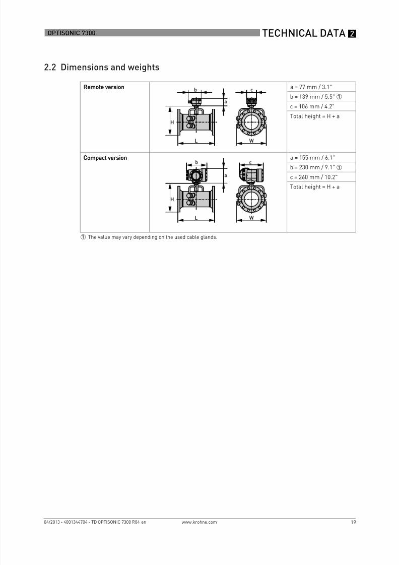
2.2 Dimensions and weights
Remote versionRemote versionRemote versionRemote version a = 77 mm / 3.1"
b = 139 mm / 5.5" 1
c = 106 mm / 4.2"Total height = H + a
Compact versionCompact versionCompact versionCompact version a = 155 mm / 6.1"b = 230 mm / 9.1" 1
c = 260 mm / 10.2"Total height = H + a
1 The value may vary depending on the used cable glands.

8/10/2019 Fit Ultrasonico 1
http://slidepdf.com/reader/full/fit-ultrasonico-1 20/40
2 TECHNICAL DATA
20
OPTISONIC 7300
www.krohne.com 04/2013 - 4001344704 - TD OPTISONIC 7300 R04 en
2.2.1 Gas flow sensor, carbon steel
EN 1092-1
Nominal size Dimensions [mm] Approxweight
[kg]DN PN [Bar] L H W Di 1
200 PN 10 460 368 429 207 46250 PN 10 530 423 474 261 66300 PN 10 580 473 517 310 81350 PN 10 610 519 542 341 109400 PN 10 640 575 583 392 141450 PN 10 620 625 623 442 170500 PN 10 670 678 670 493 202
600 PN 10 790 784 780 593 278
1 Di = inner diameter at flange face. Inner tube diameter may be smaller.
Nominal size Dimensions [mm] Approxweight
[kg]DN PN [Bar] L H W Di 1
100 PN 16 490 254 337 107 24
125 PN 16 520 283 359 133 32150 PN 16 540 315 387 159 35
1Di = inner diameter at flange face. Inner tube diameter may be smaller.
Nominal size Dimensions [mm] Approxweight
[kg]DN PN [Bar] L H W Di 1
50 PN 40 320 196 300 54.5 1165 PN 40 350 216 313 70.3 14
80 PN 40 480 230 324 82.5 19
1 Di = inner diameter at flange face. Inner tube diameter may be smaller.

8/10/2019 Fit Ultrasonico 1
http://slidepdf.com/reader/full/fit-ultrasonico-1 21/40
TECHNICAL DATA2
21
OPTISONIC 7300
www.krohne.com04/2013 - 4001344704 - TD OPTISONIC 7300 R04 en
ASME 150 lb
ASME 300 lb
Nominalsize
Dimensions Approxweight
L H W Di1
[inch] [mm] [inch] [mm] [inch] [mm] [inch] [mm] [lb] [kg]
2" 14.2 360 7.5 190 11.8 300 2.1 53 22 102½ " 15.0 380 8.3 210 12.2 310 2.5 63 33 15
3" 20.5 520 8.9 226 12.8 324 3.1 78 44 204" 21.7 550 10.1 258 13.3 337 4.0 102 64 295" 23.2 590 11.2 285 14.1 364 5.1 128 84 386" 24.4 620 12.2 312 15.2 387 6.1 154 90 418" 21.2 540 14.5 369 16.9 429 8.1 206 130 59
10" 24.0 610 16.9 428 18.7 474 10.3 260 185 8412" 26.4 670 19.4 492 20.4 512 12.2 311 266 12114" 28.7 730 21.0 534 21.3 540 13.4 340 352 16016" 30.3 770 23.3 591 23.5 597 15.4 391 462 21018" 30.7 780 25.0 635 25.0 635 17.5 441 570 25920" 32.7 830 27.3 693 27.5 699 19.3 489 607 30424" 35.8 910 31.5 801 32.0 813 23.3 591 904 411
1 Di = inner diameter at flange face. Inner tube diameter may be smaller.
Nominalsize Dimensions [inches] ApproxweightL H W Di 1
[inch] [mm] [inch] [mm] [inch] [mm] [inch] [mm] [lb] [kg]
2" 15.0 380 7.7 196 11.8 300 2.1 53 27 12
2½ " 15.4 390 8.5 217 12.2 310 2.5 63 38 173" 21.3 540 9.3 235 12.8 324 3.1 78 53 244" 22.4 570 10.7 271 13.3 337 4.0 102 86 395" 24.0 610 11.7 298 14.1 364 5.1 128 115 526" 25.2 640 13.0 331 15.0 387 6.1 154 146 66
8" 22.0 560 15.3 388 16.6 429 8.0 203 207 9410" 25.2 640 17.6 448 18.3 474 10.0 255 309 14012" 28.0 710 20.1 511 20.5 521 11.9 303 452 20514" 29.9 760 22.0 559 23.0 584 13.1 333 609 27616" 31.9 810 24.3 616 25.5 648 15.0 381 785 35618" 33.1 840 26.5 673 28.0 711 16.9 428 926 42020" 36.6 930 28.8 731 30.5 775 18.8 478 1237 56124" 38.2 970 33.5 851 36.0 914 22.6 575 1715 778
1 Di = inner diameter at flange face. Inner tube diameter may be smaller.

8/10/2019 Fit Ultrasonico 1
http://slidepdf.com/reader/full/fit-ultrasonico-1 22/40
2 TECHNICAL DATA
22
OPTISONIC 7300
www.krohne.com 04/2013 - 4001344704 - TD OPTISONIC 7300 R04 en
ASME 600 lb
ASME 900 lb
Nominalsize
Dimensions [inches] Approxweight
L H W Di1
[inch] [mm] [inch] [mm] [inch] [mm] [inch] [mm] [lb] [kg]
2" 15.7 400 7.7 196 11.5 300 1.9 49 33 152½ " 16.1 410 8.5 217 12.0 310 2.3 59 44 20
3" 22.0 560 9.3 235 12.5 324 2.9 74 66 304" 24.4 620 11.1 281 13.1 337 3.8 97 119 545" 26.0 660 12.7 323 14.1 359 4.8 122 183 836" 27.2 690 13.8 350 15.0 374 5.8 146 223 1018" 24.4 620 16.1 408 16.5 421 7.6 194 333 151
10" 27.2 690 18.3 479 20.0 508 9.6 243 531 24112" 28.3 720 20.9 530 22.0 559 11.4 289 655 29714" 29.9 760 22.4 568 23.7 603 12.5 317 798 36216" 32.7 830 25.0 635 27.0 686 14.3 364 1105 50118" 34.6 880 27.1 689 29.3 743 16.1 409 1389 63020" 35.4 900 29.5 750 32.0 813 17.9 456 1695 76924" 38.2 970 34.0 864 37.0 640 21.6 548 2438 1106
1 Di = inner diameter at flange face. Inner tube diameter may be smaller.
Nominalsize Dimensions [inches] ApproxweightL H W Di 1
[inch] [mm] [inch] [mm] [inch] [mm] [inch] [mm] [lb] [kg]
2" 17.7 450 8.7 222 11.5 300 1.7 43 64 29
2½ " 18.1 460 9.6 244 12.0 310 2.3 59 86 393" 23.6 600 9.9 251 12.5 324 2.6 67 119 544" 26.8 640 11.4 290 13.0 337 3.4 87 157 715" 26.8 680 12.6 333 13.7 359 4.6 116 240 1096" 28.7 730 14.3 363 15.0 381 5.5 140 335 152
8" 26.8 680 17.0 433 18.5 470 7.2 183 545 24710" 29.9 760 19.6 498 21.5 546 9.1 230 838 38012" 31.9 810 21.9 556 24.0 610 10.7 273 1168 53014" 33.9 860 23.1 588 25.2 641 11.8 300 1382 627
1 Di = inner diameter at flange face. Inner tube diameter may be smaller.

8/10/2019 Fit Ultrasonico 1
http://slidepdf.com/reader/full/fit-ultrasonico-1 23/40
TECHNICAL DATA2
23
OPTISONIC 7300
www.krohne.com04/2013 - 4001344704 - TD OPTISONIC 7300 R04 en
2.2.2 Converter housing
Dimensions and weights in mm and kg
Dimensions and weights in inches and lb
1 Compact housing (C)2 Field housing (F)
Version Dimensions [mm] Weight[kg]
a b c d e g h
C 202 120 155 260 137 - - 4.2F 202 120 155 - - 295.8 277 5.7
Version Dimensions [inches] Weight[lb]
a b c d e g h
C 7.75 4.75 6.10 10.20 5.40 - - 9.30F 7.75 4.75 6.10 - - 11.60 10.90 12.60

8/10/2019 Fit Ultrasonico 1
http://slidepdf.com/reader/full/fit-ultrasonico-1 24/40
2 TECHNICAL DATA
24
OPTISONIC 7300
www.krohne.com 04/2013 - 4001344704 - TD OPTISONIC 7300 R04 en
2.2.3 Mounting plate, field housing
Dimensions in mm and inches
[mm] [inches]aaaa 60 2.4bbbb 100 3.9cccc Ø 9 Ø 0.4

8/10/2019 Fit Ultrasonico 1
http://slidepdf.com/reader/full/fit-ultrasonico-1 25/40
INSTALLATION3
25
OPTISONIC 7300
www.krohne.com04/2013 - 4001344704 - TD OPTISONIC 7300 R04 en
3.1 General notes on installation
3.2 Intended use
The overall functionality of the OPTISONIC 7300OPTISONIC 7300OPTISONIC 7300OPTISONIC 7300 gas flowmeter is the continuous measurementof actual volume flow, mass flow, molar mass, flow speed, velocity of sound, gain, SNR anddiagnosis value.
3.3 Installation requirements signal converter
• Allow 10… 20 cm / 3.9 … 7.9" of space at the sides and rear of the signal converter to permitfree air circulation.
• Protect signal converter against direct solar radiation, install a sunshield if necessary.• Signal converters installed in switchgear cabinets require adequate cooling, e.g. by fan or
heat exchanger.• Do not expose the signal converter to intense vibration.
3.4 Installation requirements sensorTo secure the optimum functioning of the flowmeter, please note the following observations.
The OPTISONIC 7300 is designed for the measurement dry gasflow. Excess of liquids maydisturb the acoustic signals and should thus be avoided.The following guidelines should be observed in case occasional small amounts of liquids are tobe expected:
• Install the flow sensor in a horizontal position in a slightly descending line.• Orientate the flow sensor such that the path of the acoustic signal is in the horizontal plane.
For exchanging the transducers, please keep a free space of 1 m / 39" around the transducer.
Inspect the cartons carefully for damages or signs of rough handling. Report damage to thecarrier and to the local office of the manufacturer.
Do a check of the packing list to make sure that you have all the elements given in the order.
Look at the device nameplate to ensure that the device is delivered according to your order.Check for the correct supply voltage printed on the nameplate.
Responsibility for the use of the measuring devices with regard to suitability, intended use andcorrosion resistance of the used materials against the measured fluid lies solely with theoperator.
The manufacturer is not liable for any damage resulting from improper use or use for other thanthe intended purpose.

8/10/2019 Fit Ultrasonico 1
http://slidepdf.com/reader/full/fit-ultrasonico-1 26/40
3 INSTALLATION
26
OPTISONIC 7300
www.krohne.com 04/2013 - 4001344704 - TD OPTISONIC 7300 R04 en
3.4.1 Inlet and outlet
3.4.2 Mounting position
• Horizontally with the acoustic path in horizontal plane• Vertically
+15+15+15+15° <<<< α < -15< -15< -15< -15°
1 path flowmeter
Figure 3-1: Recommended inlet and oulet for ≤ DN80/3"1 ≥ 20 DN2 ≥ 3 DN
2 path flowmeter
Figure 3-2: Recommended inlet and oulet for ≥ DN100/4"1 ≥ 10 DN2 ≥ 3 DN
Figure 3-3: Mounting position

8/10/2019 Fit Ultrasonico 1
http://slidepdf.com/reader/full/fit-ultrasonico-1 27/40
INSTALLATION3
27
OPTISONIC 7300
www.krohne.com04/2013 - 4001344704 - TD OPTISONIC 7300 R04 en
3.4.3 Flange deviation
3.4.4 T-section
Figure 3-4: Horizontal and vertical mounting
Max. permissible deviation of pipe flange faces:Lmax - Lmin ≤ 0.5 mm / 0.02"
Figure 3-5: Flange deviation1 Lmax2 Lmin
Figure 3-6: Distance behind a T-section1 ≥ 10 DN

8/10/2019 Fit Ultrasonico 1
http://slidepdf.com/reader/full/fit-ultrasonico-1 28/40
3 INSTALLATION
28
OPTISONIC 7300
www.krohne.com 04/2013 - 4001344704 - TD OPTISONIC 7300 R04 en
3.4.5 Vibration
3.4.6 Control valve
To avoid distorted flow profiles and interference caused by valve noise in the sensor, controlvalves or pressure reducers should not be installed in the same pipeline as the flowmeter. Incase this is required, please contact the manufacturer.
3.4.7 Insulation
Figure 3-7: Avoid vibrations
Figure 3-8: Control valve
Figure 3-9: Leave vent holes free1 Vent holes
Always leave vent holes free!

8/10/2019 Fit Ultrasonico 1
http://slidepdf.com/reader/full/fit-ultrasonico-1 29/40
ELECTRICAL CONNECTIONS4
29
OPTISONIC 7300
www.krohne.com04/2013 - 4001344704 - TD OPTISONIC 7300 R04 en
4.1 Safety instructions
4.2 Signal cable (remote versions only)
The flow sensor is connected to the signal converter via the signal cable(s). A flow sensor withone acoustic path, 1 cable is required. A flow sensor with two acoustic paths, 2 cables arerequired.
All work on the electrical connections may only be carried out with the power disconnected. Takenote of the voltage data on the nameplate!
Observe the national regulations for electrical installations!
For devices used in hazardous areas, additional safety notes apply; please refer to the Exdocumentation.
Observe without fail the local occupational health and safety regulations. Any work done on theelectrical components of the measuring device may only be carried out by properly trainedspecialists.
Look at the device nameplate to ensure that the device is delivered according to your order.Check for the correct supply voltage printed on the nameplate.
Figure 4-1: Construction field version1 GFC 300 F converter2 Open connection box3 Tool for releasing connectors4 Marking on cable5 Insert cable(s) into connection box
Connect the cable on connector with similar numeral marking

8/10/2019 Fit Ultrasonico 1
http://slidepdf.com/reader/full/fit-ultrasonico-1 30/40
4 ELECTRICAL CONNECTIONS
30
OPTISONIC 7300
www.krohne.com 04/2013 - 4001344704 - TD OPTISONIC 7300 R04 en
4.3 Power supply
100… 230 VAC• Connect the protective ground conductor PE of the mains power supply to the separate
terminal in the terminal compartment of the signal converter.• Connect the live conductor to the L terminal and the neutral conductor to the N terminal.
24 VAC/DC• Connect a functional ground FE to the separate U-clamp terminal in the terminal
compartment of the signal converter.• When connecting to functional extra-low voltages, provide a facility for protective separation
(PELV) (VDE 0100 / VDE 0106 and/or IEC 364 / IEC 536 or relevant national regulations).
When this device is intended for permanent connection to the mains.It is required (for example for service) to mount an external switch or circuit breaker near thedevice for disconnection from the mains. It shall be easily reachable by the operator and markedas the disconnecting the device for this equipment.The switch or circuit breaker and wiring has to be suitable for the application and shall also be inaccordance with the local (safety) requirements of the (building) installation(e.g. IEC 60947-1 / -3)
The power terminals in the terminal compartments are equipped with additional hinged lids toprevent accidental contact.
1 100...230 VAC (-15% / +10%), 22 VA2 24 VAC/DC (AC: -15% / +10%; DC: -25% / +30%), 22 VA or 12 W
The device must be grounded in accordance with regulations in order to protect personnelagainst electric shocks.

8/10/2019 Fit Ultrasonico 1
http://slidepdf.com/reader/full/fit-ultrasonico-1 31/40
ELECTRICAL CONNECTIONS4
31
OPTISONIC 7300
www.krohne.com04/2013 - 4001344704 - TD OPTISONIC 7300 R04 en
4.4 Inputs and outputs, overview
4.4.1 Combinations of the inputs/outputs (I/Os)
This signal converter is available with various input/output combinations.
Basic version• Has 1 current output, 1 pulse output and 2 status outputs / limit switches.• The pulse output can be set as status output/limit switch and one of the status outputs as a
control input.
Ex i version• Depending on the task, the device can be configured with various output modules.• Current outputs can be active or passive.
• Optionally available also with Foundation Fieldbus and Profibus PA
Modular version• Depending on the task, the device can be configured with various output modules.
Bus systems• The device allows intrinsically safe and non intrinsically safe bus interfaces in combination
with additional modules.• For connection and operation of bus systems, please note the separate documentation.
Ex option• For hazardous areas, all of the input/output variants for the housing designs with terminal
compartment in the Ex d (pressure-resistant casing) or Ex e (increased safety) versions canbe delivered.
• Please refer to the separate instructions for connection and operation of the Ex-devices.

8/10/2019 Fit Ultrasonico 1
http://slidepdf.com/reader/full/fit-ultrasonico-1 32/40
4 ELECTRICAL CONNECTIONS
32
OPTISONIC 7300
www.krohne.com 04/2013 - 4001344704 - TD OPTISONIC 7300 R04 en
4.4.2 Description of the CG number
The last 3 digits of the CG number ( 5 , 6 and 7 ) indicate the assignment of the terminalconnections. Please see the following examples.
Examples for CG number
Description of abbreviations and CG identifier for possible optional moduleson terminals A and B
Figure 4-2: Marking (CG number) of the electronics module and input/output variants1 ID number: 62 ID number: 0 = standard3 Power supply option4 Display (language versions)5 Input/output version (I/O)6 1st optional module for connection terminal A7 2nd optional module for connection terminal B
CG 360 11 100 100...230 VAC & standard display; basic I/O: Ia or Ip & Sp/Cp & Sp & Pp/Sp
CG 360 11 7FK 100...230 VAC & standard display; modular I/O: Ia & PN/SN and optional module P N/SN & CN
CG 360 81 4EB 24 VDC & standard display; modular I/O: Ia & Pa/Sa and optional module P p/Sp & Ip
Abbreviation Identifier for CG No. DescriptionIa A Active current output
Ip B Passive current output
Pa / Sa C Active pulse output, frequency output, status output or limit switch(changeable)
Pp / Sp E Passive pulse output, frequency output, status output or limit switch(changeable)
PN / SN F Passive pulse output, frequency output, status output or limit switch acc.to NAMUR (changeable)
Ca G Active control input
Cp K Passive control input
CN H Active control input to NAMURSignal converter monitors cable breaks and short circuits acc. toEN 60947-5-6. Errors indicated on LC display. Error messages possiblevia status output.
IIna P Active current input
IInp R Passive current input
- 8 No additional module installed- 0 No further module possible

8/10/2019 Fit Ultrasonico 1
http://slidepdf.com/reader/full/fit-ultrasonico-1 33/40
ELECTRICAL CONNECTIONS4
33
OPTISONIC 7300
www.krohne.com04/2013 - 4001344704 - TD OPTISONIC 7300 R04 en
4.4.3 Fixed, non-alterable input/output versions
This signal converter is available with various input/output combinations.
• The grey boxes in the tables denote unassigned or unused connection terminals.• In the table, only the final digits of the CG no. are depicted.• Connection terminal A+ is only operable in the basic input/output version.
CG-No. Connection terminals
A+ A A- B B- C C- D D-
Basic in-/output (I/O) (Standard)1 0 0 Ip + HART® passive 1 Sp / Cp passive 2 Sp passive P p / Sp passive 2
Ia + HART® active 1
Ex-i in-/outputs (Option)2 0 0 Ia + HART® active PN / SN NAMUR 2
3 0 0 Ip + HART® passive PN / SN NAMUR 2
2 1 0 Ia active PN / SN NAMURCp passive 2
Ia + HART® active PN / SN NAMUR 2
3 1 0 Ia active PN / SN NAMURCp passive 2
Ip + HART® passive PN / SN NAMUR 2
2 2 0 Ip passive P
N / S
NNAMUR
Cp passive 2 Ia + HART®
activeP
N / S
NNAMUR 2
3 2 0 Ip passive P N / SN NAMURCp passive 2
Ip + HART® passive PN / SN NAMUR 2
1 Function changed by reconnecting2 Changeable

8/10/2019 Fit Ultrasonico 1
http://slidepdf.com/reader/full/fit-ultrasonico-1 34/40
4 ELECTRICAL CONNECTIONS
34
OPTISONIC 7300
www.krohne.com 04/2013 - 4001344704 - TD OPTISONIC 7300 R04 en
4.4.4 Alterable input/output versions
This signal converter is available with various input/output combinations.
• The grey boxes in the tables denote unassigned or unused connection terminals.• In the table, only the final digits of the CG no. are depicted.• Term. = (connection) terminal
CGno.
Connection terminals
A+ A A- B B- C C- D D-
Modular IOs (option)4 _ _ max. 2 optional modules for term. A + B Ia + HART® active Pa / Sa active 1
8 _ _ max. 2 optional modules for term. A + B Ip + HART® passive Pa / Sa active 1
6 _ _ max. 2 optional modules for term. A + B Ia + HART® active Pp / Sp passive 1
B _ _ max. 2 optional modules for term. A + B Ip + HART® passive Pp / Sp passive 1
7 _ _ max. 2 optional modules for term. A + B Ia + HART® active PN / SN NAMUR 1
C _ _ max. 2 optional modules for term. A + B Ip + HART® passive PN / SN NAMUR 1
Modbus (Option)G _ _ 2 max. 2 optional modules for term. A + B Common Sign. B
(D1)Sign. A(D0)
H _ _ 3 max. 2 optional modules for term. A + B Common Sign. B(D1)
Sign. A(D0)
1 Changeable2 Not activated bus terminator3 Activated bus terminator

8/10/2019 Fit Ultrasonico 1
http://slidepdf.com/reader/full/fit-ultrasonico-1 35/40

8/10/2019 Fit Ultrasonico 1
http://slidepdf.com/reader/full/fit-ultrasonico-1 36/40
5 APPLICATION FORM
36
OPTISONIC 7300
www.krohne.com 04/2013 - 4001344704 - TD OPTISONIC 7300 R04 en
Piping detailsNominal pipe size:
Outer diameter:Wall thickness / schedule:Pipe material:Pipe condition (old / new / painted /internal scaling / exterior rust):Liner material:Liner thickness:
Straight inlet / outlet section (DN):Upstream situation(elbows, valves, pumps):Flow orientation (vertical up / horizontal/ vertical down / other):
Environment detailsCorrosive atmosphere:Sea water:High humidity (% R.H.)Nuclear (radiation):Hazardous area:Additional details:
Hardware requirements:Accuracy requested(percentage of rate):Power supply (voltage, AC / DC):Analog output (4-20 mA)Pulse (specify minimum pulse width,pulse value):Digital protocol:Options:Remote mounted signal converter:Specify cable length:
Accessories:

8/10/2019 Fit Ultrasonico 1
http://slidepdf.com/reader/full/fit-ultrasonico-1 37/40
NOTES6
37
OPTISONIC 7300
www.krohne.com04/2013 - 4001344704 - TD OPTISONIC 7300 R04 en

8/10/2019 Fit Ultrasonico 1
http://slidepdf.com/reader/full/fit-ultrasonico-1 38/40
6 NOTES
38
OPTISONIC 7300
www.krohne.com 04/2013 - 4001344704 - TD OPTISONIC 7300 R04 en

8/10/2019 Fit Ultrasonico 1
http://slidepdf.com/reader/full/fit-ultrasonico-1 39/40
NOTES6
39
OPTISONIC 7300
www.krohne.com04/2013 - 4001344704 - TD OPTISONIC 7300 R04 en

8/10/2019 Fit Ultrasonico 1
http://slidepdf.com/reader/full/fit-ultrasonico-1 40/40