first industrial-grade coherent fiber link for optical
TRANSCRIPT
HAL Id: hal-01860814https://hal.archives-ouvertes.fr/hal-01860814
Submitted on 23 Sep 2018
HAL is a multi-disciplinary open accessarchive for the deposit and dissemination of sci-entific research documents, whether they are pub-lished or not. The documents may come fromteaching and research institutions in France orabroad, or from public or private research centers.
L’archive ouverte pluridisciplinaire HAL, estdestinée au dépôt et à la diffusion de documentsscientifiques de niveau recherche, publiés ou non,émanant des établissements d’enseignement et derecherche français ou étrangers, des laboratoirespublics ou privés.
First industrial-grade coherent fiber link for opticalfrequency standard dissemination
F Guillou-Camargo, V Ménoret, E. Cantin, O. Lopez, N Quintin, E Camisard,V. Salmon, J.-M Le Merdy, G. Santarelli, A. Amy-Klein, et al.
To cite this version:F Guillou-Camargo, V Ménoret, E. Cantin, O. Lopez, N Quintin, et al.. First industrial-grade coherentfiber link for optical frequency standard dissemination. Applied optics, Optical Society of America,2018, �10.1364/AO.57.007203�. �hal-01860814�
Letter Applied Optics 1
First industrial-grade coherent fiber link for opticalfrequency standard disseminationF. GUILLOU-CAMARGO1, V. MÉNORET1, E. CANTIN2,3, O. LOPEZ2, N. QUINTIN2,4, E. CAMISARD4, V.SALMON5, J.-M. LE MERDY5, G. SANTARELLI3,6, A. AMY-KLEIN2, P.-E. POTTIE3, B. DESRUELLE1,AND C. CHARDONNET2
1Muquans, Institut d’Optique d’Aquitaine,Rue François Mitterrand, 33400, Talence, France2Laboratoire de Physique des Lasers, Université Paris 13, CNRS, Villetaneuse, France3Laboratoire National de Métrologie et d’Essais-Systeme de Références Temps-Espace, Observatoire de Paris, Université PSL, CNRS, Paris, France4RENATER, Paris, France, 23-25 rue Daviel, 75013 Paris, France5Syrlinks, 28 rue Robert Keller, ZAC des Champs Blancs, 35510 Cesson-Sévigné, France4LP2N, Laboratoire de Photonique Numérique et Nanosciences, Institut d’Optique Graduate School, rue François Mitterrand, 33400 Talence, France*Corresponding author: [email protected]
Compiled August 23, 2018
We report on a fully bi-directional 680 km fiber link connecting two cities for which the equipment, the set up and the characterization are managed for the first time by an industrial consortium. The link uses an active telecommunication fiber n etwork w ith parallel data traffic a nd i s e quipped w ith t hree r epeater laser stations and four remote double bi-directional Erbium-doped fiber a mplifiers. We re port a sh ort te rm stabil-ity at 1 s integration time of 5.4 × 10⁻¹⁶ in 0.5 Hz band-width and a long term stability of 1.7 × 10⁻²⁰ at 65 000 s of integration time. The accuracy of the frequency transfer is evaluated as 3 × 10⁻²⁰. No shift is observed within the statistical uncertainty. We show a continu-ous operation over 5 days with an uptime of 99.93%. This performance is comparable with the state of the art coherent links established between National Metrol-ogy Institutes in Europe. It is a first s tep i n t he con-struction of an optical fiber n etwork f or m etrology in France, which will give access to an ultra-high perfor-mance frequency standard to a wide community of sci-entific users.
OCIS codes: (120.3930) Metrological instrumentation; (060.2360) Fiberoptics links and subsystems; (140.0140) Lasers and laser optics; (120.5050)Phase measurement.
http://dx.doi.org/10.1364/ao.XX.XXXXXX
1. INTRODUCTION
Optical fiber links are an emerging technology for high resolu-tion time and frequency transfer and comparison. Single modeoptical fibers are a very promising medium to carry metrologicalsignals because the guided propagation ensures excellent stabil-ity of the propagation delay, an unambiguous propagation pathand a much higher signal and lower noise than propagation in
free space over long hauls.In order to reach the lowest transfer instability, propagation
noise has to be cancelled [1]. Due to the excellent reciprocity ofthe phase accumulated forth and back, the noise can be mea-sured using a round-trip signal [2]. This can be done by retro-reflecting part of the signal, or by using a laser which is offsetphase locked to the incoming signal [3]. This latter techniquehas numerous advantages, as the light injected in the backwarddirection is constant in power. It is a key technique for the regen-eration of laser light in a cascaded link, where the link lengthis sub-divided in smaller spans, allowing for a better noise re-jection [4]. In addition it provides the opportunity to deliver auseful signal to an end-user [5]. This technique is developedsince 10 years in the optical and microwave domain [6–8] andwas recently implemented on a long-haul link of 2× 710 km,with 4 cascaded spans [5]. Cascaded link technique was usedin Europe for clock comparisons between National MetrologyInstitutes (NPL, PTB and LNE-SYRTE) [9–11].
It motivates a wide community of scientists, from fundamen-tal to applied physics and industry, to consider this technique forvarious applications [12–19]. Projects aiming at creating metro-logical networks at national and continental scale over telecom-munication fiber networks are pushing the technology forward,as their implementation requires a high level of maturity [20–23].Such metrological networks require the know-how to be trans-ferred from academia to industrial partners who can in turnprovide the scientific community with a high quality of service.As a first step towards such wide scale metrological network,we report here on the first long-haul coherent fiber link built,set-up, and managed by an industrial consortium, with supervi-sion abilities integrated into the network operating center of anational research and education network.
The manuscript is organized as follows. First we discuss thescientific objectives and subsequent requirements of a sustain-able metrological network, the way the fiber is accessed andthe equipment to be built. Then we show one of the pieces ofequipment we have developed for this network, an industrial-
Letter Applied Optics 2
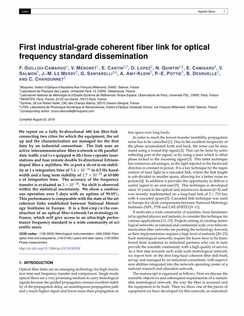
Fig. 1. Map of France with the REFIMEVE+ network. Redarrows: operational links. Blue arrows: planned links. Or-ange arrows: international cross-border links towards Braun-schweig (Germany), London (UK) and Torino (Italy). In thispaper, we focus on the link between Paris and Lille (thick redline).
grade version of the repeater laser station [5]. We focus ourdiscussion on the remote abilities and the supervision that wasimplemented to guarantee a proper operability by a networkoperation center. We report on the performance obtained using adedicated test bench, and describe the implementation and oper-ation of one link of the network, connecting two cities in Franceover 680 km of coherent fiber link. We show our experimentalresults and compare with the state-of-the-art.
2. THE REFIMEVE+ PROJECT
The frame of the work presented in this manuscript is the RE-FIMEVE+ project [23]. It aims at disseminating an ultra-stableoptical frequency standard emitting at a wavelength in the C-band of the ITU grid over 4 000 km of an active and operationaltelecommunication fiber network (see Figure 1). The network isoperated by RENATER, the French National Research and Edu-cation Network (NREN). The ultra-stable optical signal is gen-erated at the French National Metrology Institute for Time andFrequency LNE-SYRTE. It consists in continuous-wave coherentlight from a laser that is phase-locked to an ultra-stable cavity,and that can be related to the absolute frequency of frequencystandards using optical frequency combs. The ultra-stable sig-nal has to be disseminated to about 20 research laboratoriesin France, for applications ranging from comparison of opticalclocks and frequency standards to tests of advanced physics the-ories such as temporal variation of fundamental constants andgeneral relativity, ultra-high resolution atomic and molecularspectroscopy, radio-astronomy and applied physics topics likethe detection of atmospheric polluants. At the user end, theultra-stable signal can be used directly, or with the help of anoptical frequency comb.
The scientific requirements are a short-term relative fre-quency stability of the optical signal at the level of 10−15 at 1 saveraging time, and below 10−19 at one day. The accuracy of the
transferred signal must be limited by the frequency standardsthemselves. Finally, the up-time must be as close as possibleto 100%, in order to provide an efficient service to the scientificcommunity.
The fiber access is provided by RENATER. The metrologi-cal signal propagates in the same fiber as telecom data trafficusing the Dense Wavelength Division Multiplexing (DWDM)technology [24]. REFIMEVE+ uses the channel #44 centered at194.4 THz (1542.14 nm). This approach is essential for two rea-sons. First it reduces the costs as the fiber is shared and as manymaintenance operations are handle by an operating center. Sec-ond it enables the operation of a scientific instrument on thelong term, with an uptime as close as possible to 100%.
Thermal and acoustic fluctuations in the fiber introduce phasenoise which deteriorates the frequency stability of the metrologi-cal signal. To overcome this limitation, an active noise compen-sation is implemented, the round-trip phase fluctuations in thefiber being measured and corrected in real time. This requires themetrological signal to be bi-directional for optimal noise rejec-tion. Any telecom or network equipment is by-passed thanks tobi-directional Optical Add/Drop Multiplexers (OADM). Chan-nel #44 is added and dropped in the internet network with 0.2 dBinsertion loss for the data traffic. The OADM’s insertion loss forthe metrological signal is about 0.8 dB.
Moreover the signal attenuation is about 0.3 dB/km in av-erage in-field, because of losses both in the fiber and on mul-tiple optical interfaces. In every telecom shelter where a uni-directional EDFA has to be bypassed, a bi-directional EDFA am-plifies the metrological signal. However, the gain of these ampli-fiers has to be kept quite low (typically 12-21 dB) to prevent self-oscillations due to parasitic Fabry-Pérot cavity effects. Thereforelosses cannot be fully compensated with the bi-directional ED-FAs. For long-range fiber links, better amplification techniquessuch as Fiber Brillouin amplification or regeneration techniques,for example using the repeater laser stations (RLS) describedbelow, are used [5, 25]. For the REFIMEVE+ project, the solutionis to setup RLS along the link, every 300-500 km depending onthe link noise and the link loss net budget. This solution allowsus to set up cascaded links with better noise rejection and tobuild a fiber network which is both robust and reliable.
Beyond the repeater laser stations and the bi-directional ED-FAs, building a nation-wide network of 4 000 km requires otherspecific modules, such as multi-user stations, central hubs, andend-user modules. For that purpose a specific technologicaldevelopment was conducted by Laboratoire de Physique desLasers and co-workers. Technology transfer has been imple-mented to develop industrial grade equipment, a necessity for arobust and reliable operation of the REFIMEVE+ network. Notonly manufacturing, but the whole process of installing, pow-ering up, optimizing and operating the link in-field must becarried out according to industry standards so that REFIMEVE+becomes a large effective and productive research infrastructure,with upscale capacity.
Two key devices have been developed and used in the workpresented here: the bi-directional amplifiers and the repeaterlaser stations. The bi-directional amplifiers have been devel-oped by Keopsys [26]. The minimal input power is -70 dBm andthey achieve a noise figure below 5 dB with input signals aslow as -50 dBm. Even with strong input signals, output poweris limited by saturation to +5 dBm to comply with the opera-tional requirements of the network. This equipment has beenconceived to incorporate two bi-directional amplifiers in one19” rack of 1 U height and 250 mm depth. This is compliant
Letter Applied Optics 3
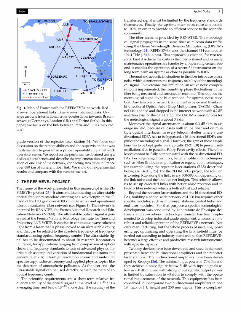
Fig. 2. Functional sketch of the remote controlled repeaterlaser station. OC: Optical Coupler, FM: Faraday Mirror, AOM:Acousto-Optic Modulator. PC: Polarisation Controller. PD:Photodiode. PLL: phase Lock Loop. CTL: Control. The track-ing oscillators used after each photo-detection are not shownin this picture. The pink rectangle represents the temperaturecontrolled box.
with the specifications of the remote shelters and nodes on thenetwork. Moreover they are remotely controlled through IP ac-cess and included into the supervision and monitoring softwarediscussed below (subsection C). The RLSs have been developedby the French company Muquans with a first step of networksupervision, and a detailed presentation is shown below.
3. THE INDUSTRIAL-GRADE REPEATER LASER STA-TION
A. ConceptsThe concept and principle of operation of RLS are describedin details elsewhere [6]. Here, we introduce this optoelectronicdevice from an engineering system point of view. The functionaldiagram displayed on Figure 2 shows the main subsystems of aRLS.
A RLS has three main roles [5]. First, it regenerates the incom-ing signal before sending it backward, enabling the compensa-tion of the noise of link N. Second, it sends regenerated light tothe N + 1 link and actively stabilizes it. Third, the repeater laserstation allows the dissemination of the compensated signal to alocal user. This output can also be used without compensationto measure the end-to-end frequency fluctuations between twoRLSs, as it will be described below.
A narrow linewidth laser diode (< 5 kHz) with an outputpower of approximately 20 mW is at the heart of the opto-electronic device. The laser of station N is combined with theincoming signal of the link to generate a beatnote, optimizedusing a polarization controller. This beatnote is used to auto-
matically phase-lock the station’s laser onto the link signal, sothat the phase fluctuations of the link are copied onto the opticalphase of the laser. Typically 1 to 2 mW of regenerated laserlight travel back in the network fiber. The optical signal to noiseratio outside the bandwidth of the lock is the one of the laserdiode, free of the accumulated spontaneous emission of the ED-FAs. This light will experience on the way back the same delayfluctuations before reaching station N − 1, where the round trippropagation noise of the link N is detected using a strongly un-balanced interferometer. The propagation noise is corrected bythe station N − 1 using an AOM.
The next span (N + 1) is fed with 1 to 2 mW of this regener-ated laser light. Again the same process occurs, the noise of thenext span is compensated after regeneration of the light in RLSN + 1.
B. Design and realizationThe repeater laser stations were developed by Muquans instrong interaction with the scientific academic partners and theRENATER network experts, so that both scientific and telecomrequirements were taken into account from the design stage.
Muquans developed the physical package and all the opti-cal subsystems, including the control of the laser source. Theelectronic subsystem is composed of three main modules: thelaser control, the interferometer temperature control, and thelink and PLL control. The latter was developed by Syrlinks acompany specialized in on-board systems for defense and spaceapplications. The RLS includes advanced automated servo loopsand an embedded Operating System for local supervision andremote control.
The interferometric setup in the RLS is critical because ithouses the optical phase detectors. The stability of the referencearms of the interferometer is essential for a good frequencystability at short and long integration times, because temporalphase fluctuations in these arms will be copied on the link [27].A specific work was conducted on the interferometer, in orderto control the optical lengths of the arms. We implementedan integration procedure to splice the components and controlthe fiber lengths to a few mm during the assembly of the inter-ferometers. Given a fiber thermal sensitivity of 37 fs/K/m, thisensures that the temperature dependence is greatly reduced. Thecomponents were also selected so that the interferometers havereproducible performances from one to the other. The opticalfiber setup is finally housed in a temperature controlled box,which is itself isolated from the environment, so that results areas much as possible reproductible. The internal temperatureof the interferometer is controlled to better than 0.05°C for a1°C external temperature variation. The temperature of theinterferometer is remotely controlled and monitored.
With this production method, a set of 33 interferometers havealready been built and characterized for the REFIMEVE+ project.Average thermal sensitivity is 0.8 fs/K with a standard deviationof 0.7 fs/K, which is comparable to the best values obtained inthe prototype stations installed in the Paris-Strasbourg link [5],but with a systematic approach.
The electronic processing and control of the signal is an essen-tial subsystem of this technology. A thorough work for ruggedi-zed design was conducted with a careful selection of robustcomponents. The RLS integrates a complex multi-function elec-tronic board with a stand-alone and smart mode of operation.This monolithic board handles all the functionalities requiredto stabilize a coherent link, such as detecting, amplifying andfiltering the signals, tracking the incoming signals, providing

Letter Applied Optics 4
Fig. 3. Scheme of the testbench with a simulated link of200 km, including two bi-directional OADMs and one bi-directional EDFA. For the noise floor measurement, the 200 kmlink is replaced by a short single mode fiber.
the reference and correction signals and automatically adjustingthe polarisation.
The industrial version of the RLS includes all the functionali-ties and automatic control of the laboratory prototypes, includ-ing its cycle-slip detector. In addition, several new functionalitiesand more control and set points were added.
The board is equipped with an FPGA and processor, thatcontrols the amplifiers gain, the servo loop parameters, andmanages the input/output functions. The board also featuresmonitoring of the temperature, input and output levels of thebeatnotes and RF signals. Several check points of the RF process-ing chain can be monitored remotely and automatically. FastFourier Transform of the error signals can be calculated in realtime. The bandwidth of the phase lock loops can be measured,saved and exported remotely, allowing for an efficient remotesetting.
The laser device is also remotely operated. In particular, theRLS features a scanning mode, used to look for the beatnotewith the incoming signal of link N.
An embedded computer manages the serial communicationswith the subsystems, and enables a back-up communicationwith a local operator. Events, such as detected cycle-slips, arelogged and time-tagged. The computer saves the data on localmemory and communicates with servers through an ethernetport and internet protocols.
An important work was conducted on the thermal manage-ment. We optimized the design and selected low power con-sumption components. This allows to slow down the aging ofthe electronic boards and reduces perturbations on the opticalinterferometer. The dimensions and weight were defined takinginto account the allocated footprint in the network nodes. RLSis composed of two 19" rack system units, one for the generalpower supply and the second for the opto-electronic system.The depths are 300 mm and 600 mm, and the heights 2 U and5 U respectively. The power consumption is 110 W, and the totalweight 17 kg.
C. Remote control and supervisionThanks to these features, the automation and remote operationof the RLS have been improved. All the lock-loops and their pa-rameters are digitally controlled and optimized through remoteaccess.
With this high level of automation, the operation of the link ismade in only three top-level steps. First, thermal regulations andthe laser are turned on. Then, the RLS checks the incoming signaland locks the laser diode on it. During this step, the polarizationis automatically adjusted. The RF gains can also be automatically
Fig. 4. Fractional frequency instability calculated from datarecorded with Λ-counter and 1-s gate time versus averagingtime. Dark red squares: Modified Allan deviation for a compen-sated 200 km laboratory link. Light red circles: Modified Allandeviation for the free-running 200 km laboratory link. Darkgreen stars: Modified Allan deviation for a short link to estimatethe noise floor of the RLS. Light green diamonds: ModifiedAllan deviation for the free-running short link.
set if needed. The RLS optimizes all the parameters until thelaser is locked. Finally, the N + 1 and local links are locked whena return signal is detected.
The RLS is programmed to automatically lock once it isstarted. If the RLS detects an input signal failure it will runthe parameters optimization loop until a satisfying lock is foundagain. Alarm signals are automatically generated and an opera-tor can remotely control the station in manual mode if necessary.
Each piece of equipment can be controlled individually. Thescientific operators of the network can monitor the status, andcheck measurement data of all the instruments. They can tuneparameters in order to optimize the performance and stabilityof the metrological network. On top of that a global supervisionsystem was implemented with a dedicated database and severaldata vizualisation functions. Furthermore, RENATER’s Net-work Operation Center (NOC) has a direct access to supervise,monitor, and control all the equipment. In case of a mainte-nance operation happening on the network, the NOC can shutdown at any time any of the REFIMEVE+ equipment, for thebest safety at work and service priority organisation. Althoughwe have not encountered emergency situations requiring to usethis function, we have validated it in our laboratory. Our workis still in progress, but in a near future the end-users will also beable to connect to the supervision server in order to monitor inreal-time the status of the metrological service and the validityof the ultra-stable signal delivered to their laboratory.
D. Operational validation
The quality control of each sub-system is carried out beforeintegration by Muquans. Here we focus on the final stage, wherethe performance of the overall system is assessed.
Indeed all the RLSs constructed for the REFIMEVE+ projectare thoroughly tested in the laboratory before being installed onthe RENATER network. At present 22 RLS were manufacturedand tested.
Letter Applied Optics 5
For that purpose, we have built a test bench, sketched outon Figure 3. We use a ultra-narrow laser diode as referencelaser (OEWaves Ultra-Narrow Linewidth Laser Module-Gen 3),with frequency noise of about 3 Hz2/Hz for Fourier frequencyabove 1 kHz. The laser frequency is kept close to 194.4 THz andmonitored on a regular basis using a calibrated wave-meter.
We use two repeater laser stations N and N + 1, N beingthe device under test and N + 1 being used both to send re-generated light backward in the link and to measure its stabil-ity. Station N is locked on the reference laser. As a first step,optimal settings for the laser of this station N are found, thenits output port OutN+1 is connected to the input port InN+1 ofthe second repeater laser station, either by a short link of 1 mor by a 200 km fiber link made of fiber spools, two OADMsand one bi-directional Keopsys EDFA. On this 200-km fiber link,we expect the overall noise level to be higher than on a reallink of the same length because of the phase fluctuations dueto the highly correlated temperature changes. Nevertheless, itallows to evaluate the RLS functions over a long fiber link beforeinstallation and gives an upper value of the link instability.
The ability of the RLS N and N + 1 to actively compensatethe noise of the link is checked by measuring its end-to-endstability. To achieve this, the user outputs of the two RLSs areconnected with a short fiber link that includes an AOM. Thissetup allows for the measurement of the end-to-end frequencyfluctuations of the link, using a two-way frequency comparisonmethod as first introduced in [28]. The beatnote signal betweenthe laser of the station N and the one transmitted on a shortfiber from station N + 1 and frequency-shifted with the AOMis detected on the PD3N of station N. In the same way, thebeatnote between the laser signal of station N + 1 and the onetransmitted on a short fiber from station N and frequency-shiftedwith the AOM is detected on the PD3N+1 of station N + 1. Bypost-processing these beatnotes, one obtains the phase differencebetween the user outputs signal of the two stations, which givesthe end-to-end phase fluctuations of the link. The beatnotesignals between the two laser stations are counted with a dead-time free frequency counter (K+K Messtechnik FXE80) operatedin Lambda-mode with a 1 s gate time.
We first measure the noise floor of the RLS under test using avery short link with a few meters of fiber. The resulting Allandeviation is shown on Figure 4. Frequency stabilities below2× 10−17 at 1 s and a few 10−20 for τ > 103 s are systematicallyachieved. The small excess of noise above τ '2 000 s, due tothe thermal periodic perturbation of the air conditioning systemacting on the station interferometer, is below 2× 10⁻²⁰. Thelong-term instability is as low as 2× 10⁻²¹ at 1 day averagingtime. This instability is well below that of the best optical clocksand shows that the RLS will not limit the link instability at the10−20 level. Moreover continuous operation of the stations overseveral weeks has been demonstrated.
We then replace the short fiber link by the 200 km fiber linkon spools. After optimisation of the laser settings, we obtainedthe results that are shown on Figure 4. The stability at 1 s is1× 10−15 and decreases to below 10−19 for τ > 104 s, limited bythe stability of the reference laser [30]. One can again observe asmall excess of noise at τ '2 000 s, due to the thermal periodicperturbation of the air conditioning system acting on the fiberspools bank. Note that this second test stage was only carried outwith the first few industrial-grade stations in order to validateall the RLS functions before in-field set-up.
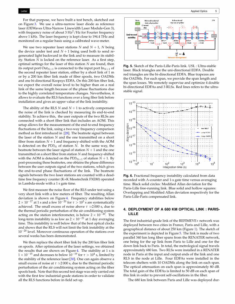
Fig. 5. Sketch of the Paris-Lille-Paris link. USL : Ultra-stablelaser. Black triangles are the uni-directional EDFA. Doublered triangles are the bi-directional EDFA. Blue trapezes arethe OADMs. For each span, we provide the span length andthe span losses. We remotely supervise and optimize 4 doublebi-directional EDFAs and 3 RLSs. Red lines refers to the ultra-stable signal.
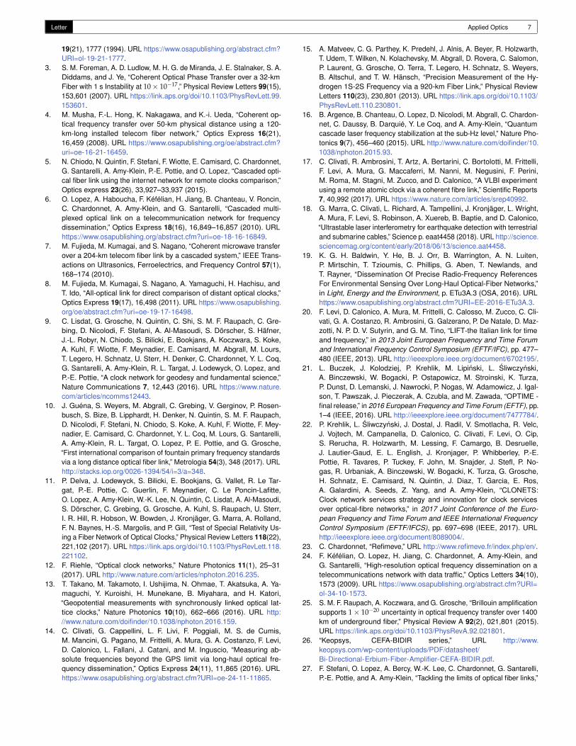
Fig. 6. Fractional frequency instability calculated from datarecorded with Λ-counter and 1-s gate time versus averagingtime. Black solid circles: Modified Allan deviation for theParis-Lille free-running link. Blue solid and hollow squares:Overlapping and Modified Allan deviation respectively for theParis-Lille-Paris compensated link.
4. DEPLOYMENT OF A 680 KM OPTICAL LINK : PARIS-LILLE
The first industrial-grade link of the REFIMEVE+ network wasdeployed between two cities in France, Paris and Lille, with ageographical distance of about 250 km (Figure 1). The sketch ofthe experiment is depicted in Figure 5. The link is made of twoparallel 340 km long fiber spans from the RENATER network,one being for the up link from Paris to Lille and one for thedown link back to Paris. In total, the metrological signal travelsapproximately 680 km. Two RLSs were installed in a RENATERnode in Paris at the input and output ends of the link and oneRLS in the node at Lille. Four EDFAs were installed in thetelecom shelters with 10 OADMs along the link on each span.The optical attenuation on each span is approximately 80 dB.The total gain of the EDFAs is limited to 50 dB on each span ofthis link in order to prevent self-oscillations in the fiber.
The 680 km link between Paris and Lille was deployed dur-

Letter Applied Optics 6
ing the summer of 2017. Installing all the RLSs and EDFAs inthe RENATER nodes and shelters took approximately one week.Once all the equipment was set up, remote communication waschecked and the link was stabilized, without any malfunction.At that stage, the lasers were locked but many cycle slips de-graded the stability and the accuracy of the frequency transfer.The best stability level as shown on Figure 6 was reached afterfurther optimizations that lasted approximately 3 weeks. Be-cause the RLS and EDFAs were fully tested before installation,this period of time was dedicated to adjusting the amplifier andlock loop gains, focusing on the dynamics of the link itself ratherthan on the equipment. Overall the installation and adjustmentprocess took under a month. Once the phase lock loops pa-rameters and the gain of the optical amplifiers were optimized,the cascaded link was operated continuously for several weeks.Even when perturbations occur because of thermal fluctuations,acoustic noise or activity on the network, events are time-taggedand the RLSs automatically re-lock in less than one minute. Theinterferometer temperature experienced fluctuations with a stan-dard deviation of .065 K during the acquisition of the data.
To estimate the stability of the link, we measure the end-to-end signal between the two RLS in Paris, using again a dead-timefree frequency counter operated in Λ-mode with a 1-s gate time.By measuring synchronously the correction signal applied tothe AOM of the first station (station 1 in Figure 5), we can alsoestimate the free-running noise on the first span of the link.
Figure 6 shows the free-running stability and the Overlappingand Modified Allan deviation of the compensated link during acontinuous 5-day measurement. When the link is compensated,we achieve a frequency stability of 5.4× 10⁻¹⁶ at 1 s integrationtime, which averages down to 1.7× 10⁻²⁰ at 65 000s. At shortterm, it is limited by the propagation delay and at long term bylaser and interferometer noise [27, 29–31]. This stability is com-parable to state-of-the-art ultra-stable optical frequency transferobtained by research laboratories.
The accuracy of the frequency transfer is assessed by calcu-lating the mean of the frequency data set, and the statisticaluncertainty given by the Overlapping Allan deviation at longintegration time [32]. We took the upper error bar at 65 000 s fora conservative estimate. One obtains −3× 10⁻²¹ ± (3× 10⁻²⁰).Note that the uncertainty is not limited by the inaccuracy of thelocal RF oscillator [5].
In order to better appreciate the performances of the link,Figure 7 shows the end-to-end phase fluctuations during thismeasurement. Over this time period, the RLS tagged 23 cycleslips. Most of them correspond to polarization adjustments. Intotal 285 data points were removed from the 432 000 s long data.The integrated phase fluctuations of the end-to end signal are ina range of 10 radians over 5 days. The corresponding time error,expressed in fs, is less than 8 fs. The up-time over this period isas high as 99.93%.
This performance, both in terms of stability and accuracy,meets the requirements of the REFIMEVE+ project.
5. CONCLUSIONS AND PERSPECTIVES
We demonstrated the setting-up and exploitation of the firstindustrial-grade coherent optical fiber link, as part of the RE-FIMEVE+ network. We show a state-of-the-art relative frequencystability and accuracy at 65 000 s integration time below the10−19 level over a cascaded link of 680 km. Moreover theindustrial-grade repeater laser station contribution to the in-stability is below 2× 10⁻²⁰ for integration times higher than
Fig. 7. End-to-end phase fluctuations after propagation over a680 km fiber link.
1 000 s. We also report an uptime of 99.93% over 5 continuousdays, which is very promising regarding the effectiveness ofREFIMEVE+ to the end-user.
With the work presented here, we totally fulfill the require-ments of the REFIMEVE+ project. We have demonstrated thebasics tools for the upcoming extension of this network. Wehave also built a test bench to validate the serial production ofrepeater laser stations.
Furthermore, we have set-up our production capacity for afull deployment of the network within the next 2 years. Thedeployment time we can achieve is now comparable to that of atelecommunication link for data traffic, which shows our highlevel of maturity and concerns about the control of schedule andcosts. With this work, the technological readiness level (TRL) ofthe RLSs was increased from 5-6 to 8. The TRL of the cascadedlinks with EDFAs and RLSs is now set as high as 8 [33].
Regarding the hardware developments, the next steps areto reach the same level of maturity for the end-user and eaves-dropping setups. Another major concern is the central hub ofthe network that is being developed with the concept of super-station [34]. Finally one crucial challenge relates to the networksupervision. Supervision software tools need to be further de-veloped and implemented. We demonstrate here our ability togather many informations into a complex database. The nextchallenge is to optimally utilize this database for the most ef-fective network and the best scientific use. Our objective ofdisseminating frequency standard with high availability is nowclose to hand.
6. FUNDING INFORMATION
We acknowledge funding support from the Agence Nationalede la Recherche (Equipex REFIMEVE+ ANR-11-EQPX-0039).
REFERENCES
1. L. Primas, G. Lutes, and R. Sydnor, “Fiber optic frequency transfer link,”in Proceedings of the 42nd Annual Frequency Control Symposium,1988, pp. 478–484 (1988).
2. L.-S. Ma, P. Jungner, J. Ye, and J. L. Hall, “Delivering the same opticalfrequency at two places: accurate cancellation of phase noise intro-duced by an optical fiber or other time-varying path,” Optics Letters
Letter Applied Optics 7
19(21), 1777 (1994). URL https://www.osapublishing.org/abstract.cfm?URI=ol-19-21-1777.
3. S. M. Foreman, A. D. Ludlow, M. H. G. de Miranda, J. E. Stalnaker, S. A.Diddams, and J. Ye, “Coherent Optical Phase Transfer over a 32-kmFiber with 1 s Instability at 10× 10−17,” Physical Review Letters 99(15),153,601 (2007). URL https://link.aps.org/doi/10.1103/PhysRevLett.99.153601.
4. M. Musha, F.-L. Hong, K. Nakagawa, and K.-i. Ueda, “Coherent op-tical frequency transfer over 50-km physical distance using a 120-km-long installed telecom fiber network,” Optics Express 16(21),16,459 (2008). URL https://www.osapublishing.org/oe/abstract.cfm?uri=oe-16-21-16459.
5. N. Chiodo, N. Quintin, F. Stefani, F. Wiotte, E. Camisard, C. Chardonnet,G. Santarelli, A. Amy-Klein, P.-E. Pottie, and O. Lopez, “Cascaded opti-cal fiber link using the internet network for remote clocks comparison,”Optics express 23(26), 33,927–33,937 (2015).
6. O. Lopez, A. Haboucha, F. Kéfélian, H. Jiang, B. Chanteau, V. Roncin,C. Chardonnet, A. Amy-Klein, and G. Santarelli, “Cascaded multi-plexed optical link on a telecommunication network for frequencydissemination,” Optics Express 18(16), 16,849–16,857 (2010). URLhttps://www.osapublishing.org/abstract.cfm?uri=oe-18-16-16849.
7. M. Fujieda, M. Kumagai, and S. Nagano, “Coherent microwave transferover a 204-km telecom fiber link by a cascaded system,” IEEE Trans-actions on Ultrasonics, Ferroelectrics, and Frequency Control 57(1),168–174 (2010).
8. M. Fujieda, M. Kumagai, S. Nagano, A. Yamaguchi, H. Hachisu, andT. Ido, “All-optical link for direct comparison of distant optical clocks,”Optics Express 19(17), 16,498 (2011). URL https://www.osapublishing.org/oe/abstract.cfm?uri=oe-19-17-16498.
9. C. Lisdat, G. Grosche, N. Quintin, C. Shi, S. M. F. Raupach, C. Gre-bing, D. Nicolodi, F. Stefani, A. Al-Masoudi, S. Dörscher, S. Häfner,J.-L. Robyr, N. Chiodo, S. Bilicki, E. Bookjans, A. Koczwara, S. Koke,A. Kuhl, F. Wiotte, F. Meynadier, E. Camisard, M. Abgrall, M. Lours,T. Legero, H. Schnatz, U. Sterr, H. Denker, C. Chardonnet, Y. L. Coq,G. Santarelli, A. Amy-Klein, R. L. Targat, J. Lodewyck, O. Lopez, andP.-E. Pottie, “A clock network for geodesy and fundamental science,”Nature Communications 7, 12,443 (2016). URL https://www.nature.com/articles/ncomms12443.
10. J. Guéna, S. Weyers, M. Abgrall, C. Grebing, V. Gerginov, P. Rosen-busch, S. Bize, B. Lipphardt, H. Denker, N. Quintin, S. M. F. Raupach,D. Nicolodi, F. Stefani, N. Chiodo, S. Koke, A. Kuhl, F. Wiotte, F. Mey-nadier, E. Camisard, C. Chardonnet, Y. L. Coq, M. Lours, G. Santarelli,A. Amy-Klein, R. L. Targat, O. Lopez, P. E. Pottie, and G. Grosche,“First international comparison of fountain primary frequency standardsvia a long distance optical fiber link,” Metrologia 54(3), 348 (2017). URLhttp://stacks.iop.org/0026-1394/54/i=3/a=348.
11. P. Delva, J. Lodewyck, S. Bilicki, E. Bookjans, G. Vallet, R. Le Tar-gat, P.-E. Pottie, C. Guerlin, F. Meynadier, C. Le Poncin-Lafitte,O. Lopez, A. Amy-Klein, W.-K. Lee, N. Quintin, C. Lisdat, A. Al-Masoudi,S. Dörscher, C. Grebing, G. Grosche, A. Kuhl, S. Raupach, U. Sterr,I. R. Hill, R. Hobson, W. Bowden, J. Kronjäger, G. Marra, A. Rolland,F. N. Baynes, H.-S. Margolis, and P. Gill, “Test of Special Relativity Us-ing a Fiber Network of Optical Clocks,” Physical Review Letters 118(22),221,102 (2017). URL https://link.aps.org/doi/10.1103/PhysRevLett.118.221102.
12. F. Riehle, “Optical clock networks,” Nature Photonics 11(1), 25–31(2017). URL http://www.nature.com/articles/nphoton.2016.235.
13. T. Takano, M. Takamoto, I. Ushijima, N. Ohmae, T. Akatsuka, A. Ya-maguchi, Y. Kuroishi, H. Munekane, B. Miyahara, and H. Katori,“Geopotential measurements with synchronously linked optical lat-tice clocks,” Nature Photonics 10(10), 662–666 (2016). URL http://www.nature.com/doifinder/10.1038/nphoton.2016.159.
14. C. Clivati, G. Cappellini, L. F. Livi, F. Poggiali, M. S. de Cumis,M. Mancini, G. Pagano, M. Frittelli, A. Mura, G. A. Costanzo, F. Levi,D. Calonico, L. Fallani, J. Catani, and M. Inguscio, “Measuring ab-solute frequencies beyond the GPS limit via long-haul optical fre-quency dissemination,” Optics Express 24(11), 11,865 (2016). URLhttps://www.osapublishing.org/abstract.cfm?URI=oe-24-11-11865.
15. A. Matveev, C. G. Parthey, K. Predehl, J. Alnis, A. Beyer, R. Holzwarth,T. Udem, T. Wilken, N. Kolachevsky, M. Abgrall, D. Rovera, C. Salomon,P. Laurent, G. Grosche, O. Terra, T. Legero, H. Schnatz, S. Weyers,B. Altschul, and T. W. Hänsch, “Precision Measurement of the Hy-drogen 1S-2S Frequency via a 920-km Fiber Link,” Physical ReviewLetters 110(23), 230,801 (2013). URL https://link.aps.org/doi/10.1103/PhysRevLett.110.230801.
16. B. Argence, B. Chanteau, O. Lopez, D. Nicolodi, M. Abgrall, C. Chardon-net, C. Daussy, B. Darquié, Y. Le Coq, and A. Amy-Klein, “Quantumcascade laser frequency stabilization at the sub-Hz level,” Nature Pho-tonics 9(7), 456–460 (2015). URL http://www.nature.com/doifinder/10.1038/nphoton.2015.93.
17. C. Clivati, R. Ambrosini, T. Artz, A. Bertarini, C. Bortolotti, M. Frittelli,F. Levi, A. Mura, G. Maccaferri, M. Nanni, M. Negusini, F. Perini,M. Roma, M. Stagni, M. Zucco, and D. Calonico, “A VLBI experimentusing a remote atomic clock via a coherent fibre link,” Scientific Reports7, 40,992 (2017). URL https://www.nature.com/articles/srep40992.
18. G. Marra, C. Clivati, L. Richard, A. Tampellini, J. Kronjäger, L. Wright,A. Mura, F. Levi, S. Robinson, A. Xuereb, B. Baptie, and D. Calonico,“Ultrastable laser interferometry for earthquake detection with terrestrialand submarine cables,” Science p. eaat4458 (2018). URL http://science.sciencemag.org/content/early/2018/06/13/science.aat4458.
19. K. G. H. Baldwin, Y. He, B. J. Orr, B. Warrington, A. N. Luiten,P. Mirtschin, T. Tzioumis, C. Phillips, G. Aben, T. Newlands, andT. Rayner, “Dissemination Of Precise Radio-Frequency ReferencesFor Environmental Sensing Over Long-Haul Optical-Fiber Networks,”in Light, Energy and the Environment, p. ETu3A.3 (OSA, 2016). URLhttps://www.osapublishing.org/abstract.cfm?URI=EE-2016-ETu3A.3.
20. F. Levi, D. Calonico, A. Mura, M. Frittelli, C. Calosso, M. Zucco, C. Cli-vati, G. A. Costanzo, R. Ambrosini, G. Galzerano, P. De Natale, D. Maz-zotti, N. P. D. V. Sutyrin, and G. M. Tino, “LIFT-the Italian link for timeand frequency,” in 2013 Joint European Frequency and Time Forumand International Frequency Control Symposium (EFTF/IFC), pp. 477–480 (IEEE, 2013). URL http://ieeexplore.ieee.org/document/6702195/.
21. L. Buczek, J. Kolodziej, P. Krehlik, M. Lipinski, L. Sliwczynski,A. Binczewski, W. Bogacki, P. Ostapowicz, M. Stroinski, K. Turza,P. Dunst, D. Lemanski, J. Nawrocki, P. Nogas, W. Adamowicz, J. Igal-son, T. Pawszak, J. Pieczerak, A. Czubla, and M. Zawada, “OPTIME -final release,” in 2016 European Frequency and Time Forum (EFTF), pp.1–4 (IEEE, 2016). URL http://ieeexplore.ieee.org/document/7477784/.
22. P. Krehlik, L. Sliwczynski, J. Dostal, J. Radil, V. Smotlacha, R. Velc,J. Vojtech, M. Campanella, D. Calonico, C. Clivati, F. Levi, O. Cip,S. Rerucha, R. Holzwarth, M. Lessing, F. Camargo, B. Desruelle,J. Lautier-Gaud, E. L. English, J. Kronjager, P. Whibberley, P.-E.Pottie, R. Tavares, P. Tuckey, F. John, M. Snajder, J. Stefl, P. No-gas, R. Urbaniak, A. Binczewski, W. Bogacki, K. Turza, G. Grosche,H. Schnatz, E. Camisard, N. Quintin, J. Diaz, T. Garcia, E. Ros,A. Galardini, A. Seeds, Z. Yang, and A. Amy-Klein, “CLONETS:Clock network services strategy and innovation for clock servicesover optical-fibre networks,” in 2017 Joint Conference of the Euro-pean Frequency and Time Forum and IEEE International FrequencyControl Symposium (EFTF/IFCS), pp. 697–698 (IEEE, 2017). URLhttp://ieeexplore.ieee.org/document/8089004/.
23. C. Chardonnet, “Refimeve,” URL http://www.refimeve.fr/index.php/en/.24. F. Kéfélian, O. Lopez, H. Jiang, C. Chardonnet, A. Amy-Klein, and
G. Santarelli, “High-resolution optical frequency dissemination on atelecommunications network with data traffic,” Optics Letters 34(10),1573 (2009). URL https://www.osapublishing.org/abstract.cfm?URI=ol-34-10-1573.
25. S. M. F. Raupach, A. Koczwara, and G. Grosche, “Brillouin amplificationsupports 1× 10⁻²⁰ uncertainty in optical frequency transfer over 1400km of underground fiber,” Physical Review A 92(2), 021,801 (2015).URL https://link.aps.org/doi/10.1103/PhysRevA.92.021801.
26. “Keopsys, CEFA-BIDIR series,” URL http://www.keopsys.com/wp-content/uploads/PDF/datasheet/Bi-Directional-Erbium-Fiber-Amplifier-CEFA-BIDIR.pdf.
27. F. Stefani, O. Lopez, A. Bercy, W.-K. Lee, C. Chardonnet, G. Santarelli,P.-E. Pottie, and A. Amy-Klein, “Tackling the limits of optical fiber links,”

Letter Applied Optics 8
Journal of the Optical Society of America. B, Optical Physics 32, 787–797 (2015).
28. C. E. Calosso, E. Bertacco, D. Calonico, C. Clivati, G. A. Costanzo,M. Frittelli, F. Levi, A. Mura, and A. Godone, “Frequency transfer via atwo-way optical phase comparison on a multiplexed fiber network,” Op-tics Letters 39(5), 1177–1180 (2014). URL https://www.osapublishing.org/abstract.cfm?uri=ol-39-5-1177.
29. P. A. Williams, W. C. Swann, and N. R. Newbury, “High-stabilitytransfer of an optical frequency over long fiber-optic links,” Jour-nal of the Optical Society of America B 25(8), 1284 (2008). URLhttps://www.osapublishing.org/abstract.cfm?URI=josab-25-8-1284.
30. W.-K. Lee, F. Stefani, A. Bercy, O. Lopez, A. Amy-Klein, and P.-E.Pottie, “Hybrid fiber links for accurate optical frequency comparison,”Applied Physics B 123(5), 161 (2017). URL http://dx.doi.org/10.1007/s00340-017-6736-5.
31. D. Xu, W.-K. Lee, F. Stefani, O. Lopez, A. Amy-Klein, and P.-E.Pottie, “Studying the fundamental limit of optical fiber links to the10−21 level,” Optics Express 26(8), 9515–9527 (2018). URL https://www.osapublishing.org/oe/abstract.cfm?uri=oe-26-8-9515.
32. E. Benkler, C. Lisdat, and U. Sterr, “On the relation between uncer-tainties of weighted frequency averages and the various types of Allandeviations,” Metrologia 52(4), 565 (2015). URL http://stacks.iop.org/0026-1394/52/i=4/a=565.
33. “The TRL Scale as a Research & Innovation Policy Tool, EARTORecommendations,” URL http://cache.media.education.gouv.fr/file/NMP/92/3/The_TRL_Scale_as_a_R_I_Policy_Tool_-_EARTO_Recommendations_-_Final_318923.pdf.
34. E. Cantin, N. Quintin, F. Wiotte, C. Chardonnet, A. Amy-Klein, O. Lopez,P.-E. Pottie, G. Santarelli, and E. Camisard, “Progress on the RE-FIMEVE+ project for optical frequency standard dissemination,” in2017 Joint Conference of the European Frequency and Time Forumand IEEE International Frequency Control Symposium (EFTF/IFCS),pp. 378–380 (IEEE, 2017). URL http://ieeexplore.ieee.org/document/8088897/.