first ever 40gigabit internet connection to the home challenge
TRANSCRIPT

1
Stupi LLC, 101 1St Street, Suite 553, Los Altos, CA 94022, USA
Peter Löthberg, <[email protected]>
Challenge:A: There was no Internet at my parents
house and the local ISP’s suck (the lack of performance is scary, and they have no IPv6 etc.).
B: Explain that if your house is fiber attached by a open neutral provider, there are many possibilities
C: We have hit another Bellhead bump in the road to remove unnecessary elements from the IP network. If my mother can make it work i, it must be a political/”my_job problem”.
First Ever 40Gigabit Internet Connection to the Home
Ripe 55, Amsterdam, October 2007

2
Mamma NET
Why:I’m crazy (sorry, no banana for pointing that out)The Swedish policy scene is full of FUD Fiber based optical networks are flexible and future proofVideo Conferencing with my parentsBBQ Bellheads said it can’t be doneIt has not been done, so why not give it a tryEvaluate the performance of SUnet’s new optical networkIt’s better than DSL and supports large packets..etc...
.... and to see if I can outperform “Mr Hype” in press releases

3
Mamma NET
Yes, 40G to my mom’s house isn’t what everyone can do:
The reason I’m giving this talk at Ripe is to help you break down the barriers that your transport people put up to stop you from building more efficient IP networks.
Remember X25, Frame Delay, ATM, Routers directly attached to DWDM systems without ADM’s etc
This is simple, you can do it, just look at the design criteria;If you have enough OSNRProperly manage your chromatic dispersionAre within PMD limitsProperly clean your connectors
4Ripe 55, Amsterdam, October 2007
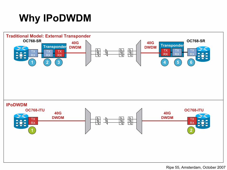
Why IPoDWDM
40G DWDM
40G DWDM
TXRX
TXRX
TXRX
TXRX
TXRX
40GDWDMTX
RX
TXRX
TXRX
OC768-SR
40GDWDM
OC768-SR
OC768-ITU OC768-ITU
Transponder Transponder
1 2 3 5
1 2
4
IPoDWDM
Traditional Model: External Transponder
6

5
Special Thanks to:....Mom and DADHans Wallberg and Börje Josefsson SUnetThe NuNoc STAFFSanta Claus, Kelly Ahuja, Björn Ehn, Walid Wakim CiscoHafstein Johnsson, Raimo Vekhajarvi, Malin Thorsen City of KarlstadHakan Syren, ELTEL NetworksRoss Saunders, Stratalight ”Ethernet Micke” Abrahamson, LM Jogback Tele2Marko Ivanov CienaAnders Magnusson LTUThomas Svensk Imtech
Thanks to:....
”It cant be done!” BBQ divisionNiklas Montin, Håkan Karlsson, Jim Houts, Dennis Davidsson ,Dave Meyer, Samer Parikh, and many more CiscoLeon Pavlov MobinetLars Molin GeosonicChase Cotton, Wes George, Björn Carlsson, Dave Harris SprintBob Rodeo, Mike Pellegrini CienaKalix FiberFredrik Holmqvist DCS

6Ripe 55, Amsterdam, October 2007
MotherNet Don’t forget to take the cards out before attempting shiping.
Greatly improves value of the 1988 WV-bus...

7Ripe 55, Amsterdam, October 2007
Moving the broadband router in to the garage.
My dad is performing damage management.
Leon is providing muscle resources
8Ripe 55, Amsterdam, October 2007
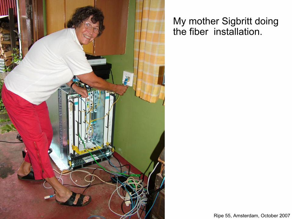
My mother Sigbritt doing the fiber installation.

9Ripe 55, Amsterdam, October 2007
MotherNet

10Ripe 55, Amsterdam, October 2007
World’s First and Fastest Internet Connection to the home, 40Gig!
Karlstad Stockholm
412.1Km
CRS-1 w/ Integrated 40Gig DWDM Optics
412Km3.5 dBQ
Un-optimized
Karlstad
Stockholm
40Gig CircuitOver Fiber
No Repeaters
40Gig, Plug and Play Circuit Turn Up“The most difficult part of the whole project was installing
Windows on Sigbritt’s PC,”said Hafsteinn Jonsson of Karlstad Stadsnat.

11Ripe 55, Amsterdam, October 2007
Network Layout
CRS-140G
DWDM10Km
TXRX
Existing Transport
OC768-ITU(ODB)
3rd Party DWDM Provider(Ciena)
40Gig Integrated DWDMOptics on CRS-1
Connectivity at Stockholm and Karlstad

12Ripe 55, Amsterdam, October 2007
Physical Network
CRS-140G
DWDM10KM
TXRX
Existing Transport
OC768-ITU(ODB)
3rd Party DWDM Provider( Ciena )
40Gig IntegratedDWDMOptics on CRS-1
84.3Kmor
(19.6dB)
102.2Kmor
(23.3dB)
107.4Kmor
(24.5dB)
110.8Kmor
(26.6dB)
Cummulative Fiber Dispersion W2E (at 1545 nm)
-1200-1000
-800-600-400-200
0200400600
Stockholm Savja Vasteras Orebro Karlstad Cummulative Fiber Dispersion W2E(at 1545 nm)
CRS-1
40GDWDMTX
RX
Existing Transport
OC768-ITU(ODB)
3rd Party DWDM Provider (Ciena) 40Gig IntegratedOptics on CRS-1
-501psDCU
Line CD Map, Does not include DCU at CRS
RXTX

13Ripe 55, Amsterdam, October 2007
The Local Loop: 10 795m
Hafstein Johnsson
Malin Thorsen
Installation and measurements by ELTEL Networks

14Ripe 55, Amsterdam, October 2007

15Ripe 55, Amsterdam, October 2007
Broad Band to My Mother, Optics
SavjaStockholm Orebro KarlstadVasteras
60 50 11080 80
23.3dB102.2km
0.062ps/n
19.6dB84.3km
0.081ps/n
24.5dB107.4km
0.122ps/n
26.6dB110.8km
0.188ps/n
5dB10.8km
0.0193ps/n
Sunet / Opto SUnet Karlstad Stadsnat
30
Ciena Band 5, Channel 5, Frequency = 193.30 THz, Wavelength = 1550.918 nm, MSA Channel 57
40G MPR
70 120 110110
23.3dB102.2km
0.167ps/n
19.6dB84.3km
0.138ps/n
24.5dB107.4km
0.098ps/n
26.6dB110.8km
0.079ps/n
40G MPR
+10 +15dB
120EDFA amplifier
Dispersion Compensation fiber SMF28 equivalent length
RX Power = -4.41 dBmTX Power = 1.19 dBm
TX Power = -2.81 dBmRX Power = -12.91 dBm
4.8dB10.8km
0.0385ps/n
PMD=0.472 ps+1.5ps=2.472ps
PMD=0.501 ps+1.5ps=2.501ps

16Ripe 55, Amsterdam, October 2007
MotherNet

17Ripe 55, Amsterdam, October 2007
CHAN 5
LC UPC connector

18Ripe 55, Amsterdam, October 2007
Stupi Test Network

19Ripe 55, Amsterdam, October 2007
Mothers Alternate use of the broadband gateway

20Ripe 55, Amsterdam, October 2007
Power Consumption
Operated for 48 days
- Power 1.56 KW
- Cost EUR 293/month

21Ripe 55, Amsterdam, October 2007
MotherNet
D-WDM 1-GE SFP,
Same color as the 40G signal
Same setup at Stockholm side

22Ripe 55, Amsterdam, October 2007
MotherNet

23Ripe 55, Amsterdam, October 2007
Optical ImpairmentsDWDM Building Blocks
TranspondersDWDM
Multiplexer
OpticalAmplifiers
OpticalAdd/Drop
ReceiveTransponders
DWDMDemultiplexer
ITU-T Transmitters
OA OADM OA
LTE
LTE
LTE
OEO
OEO
LTE
LTE
LTE

24Ripe 55, Amsterdam, October 2007
Optical Impairments
Chromatic Dispersion (CD)The refractive index of fiber has a wavelength dependence. This causes the higher frequencies to travel faster then lower frequencies causing a pulse broadening effect. Measured in ps/nm*km, threshold / limit measured in ps/nm.
Confusion, do I want it or not? Is it good or bad?Reducing Dispersion will increase distance and performance
Reducing / Eliminating Dispersion will also increase nonlinear effects thus limiting distance / performance
Dispersion Compensating Units (DCUs) are used to compensate for CD
tt+16.7ps
1 Km of SMF28 Fiber16.7 ps/nm

25Ripe 55, Amsterdam, October 2007
Optical Impairments
Optical Signal-to-Noise RatioCompensate for Attenuation with Optical Amplifier
Compensate for Dispersion with DCU
Can we now travel an infinite distance without Regen?No! We are limited by OSNR (besides other effects)
As we start to cascade Amplifiers we introduce noise in the form of ASE
Signal degradation caused by 2 factors:
1. Noise to noise beatings
2. Noise to signal interference
#1 we can take care of using a narrowband filter
#2 is the true problem since it is beating against the actual signal hence key limiting factor

26Ripe 55, Amsterdam, October 2007
Optical Impairments
How do we calculate Signal to Noise?In its simplest form OSNR is:
OSNR = 58 + Pin - NF - 10*log(N) - 10*log(M)Where:58 = power density in 0.1nm BWPin = input to EDFANF = Noise Figure of EDFAN = # of Optical ChannelsM = # of Amps in cascade
27Ripe 55, Amsterdam, October 2007
Optical ImpairmentsG.709 and Forward Error Correction (FEC)
Ethernet is the transport of choicePerformance Monitors similar to SONET would be required to ensure proactive monitoring and health of system
SolutionWavelength monitoring via standards based G.709
Provides SONET like OAM&P
Standard specifies OTU1(2.5G), OTU2(10G) and OTU3(40G)
Ethernet cost with SONET like OAM&P

28Ripe 55, Amsterdam, October 2007
Optical ImpairmentsG.709 Wrapper
3825
4080
1 7 8 14 15 16 17 3824
1
2
3
4
OPU k PayloadO
PUk
OH
OPUkŃ Optical Channel Payload Unit
ODUk
ODUkŃ Optical Channel Data Unit
Client SignalMapped in
OPUk Payload
Client Signal
OTUkFEC
OTUk OH
OTUkŃ Optical Channel Transport Unit
Alignm
Alignment
k Indicatesthe Order:1 2.5G2 10G3 40G

29Ripe 55, Amsterdam, October 2007
Log
(BER
)
4 5 6 7 8 9 10 11 12 13 14 15–15
–14–13
–12
–11
–10–9
–8
–7
–6–5
–4
–3
–2–1
0
S/N (dB)
UncodedNo FEC
G.709RS(255,239)
Raw Channel BER=1.5e-3
EFEC=8.4 dBFEC=6.2 dB
Optical ImpairmentsFEC
FEC extends reach and design flexibility, at “silicon cost”
G.709 standard improves OSNR tolerance by 6.2 dB (at 10–15 BER)
Offers intrinsic performance monitoring (error statistics)
Higher gains (8.4dB) possible by enhanced FEC (with same G.709 overhead)
Benefit: FEC/EFEC Extends Reach and Offers 10–15 BER
30Ripe 55, Amsterdam, October 2007
Optical Impairments
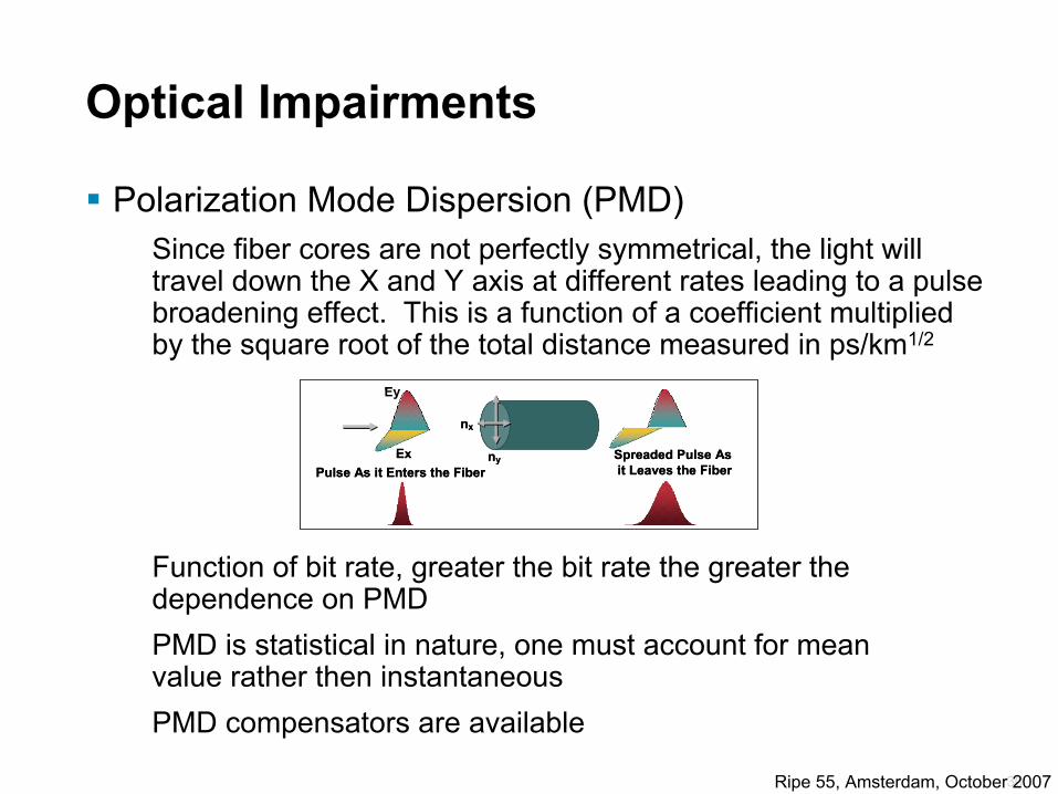
Polarization Mode Dispersion (PMD)Since fiber cores are not perfectly symmetrical, the light will travel down the X and Y axis at different rates leading to a pulse broadening effect. This is a function of a coefficient multiplied by the square root of the total distance measured in ps/km1/2
Function of bit rate, greater the bit rate the greater the dependence on PMDPMD is statistical in nature, one must account for mean value rather then instantaneousPMD compensators are available
nx
nyEx
Ey
Pulse As it Enters the FiberSpreaded Pulse As it Leaves the Fiber
nx
nyEx
Ey
Pulse As it Enters the FiberSpreaded Pulse As it Leaves the Fiber

31Ripe 55, Amsterdam, October 2007
Optical Impairments
FPM or FWMBeating between two channels at their difference frequency, modulates the phase at that frequency generating new tones as side bands. These new products interfere with other channels
BER degradation
Counter MeasuresUnequal Channel Spacing
Increase Channel Spacing
Chromatic Dispersion, waves alternate in and out of phase, reducing mixing efficiency
Total Beats = N(N-1)^2
λ1 λ2 λ3
f113 f112
f123
f213
f223 f132
f312
f221 f332
f321
f231
f331

32Ripe 55, Amsterdam, October 2007
Optical Impairments
XPMThis arises due to the weak dependence of the refractive index on intensity: n=n0 + n2*I. Here the nonlinear refractive index modulates one of the carriers onto the other.
Pulse broadening gets exaggerated with Chromatic Dispersion
Counter MeasuresChromatic Dispersion, the group velocity causes the interfering pulse to walk thru the other
Larger spacing between carriers

33Ripe 55, Amsterdam, October 2007
Modulation SchemesAcronyms
(N)RZ—(Non) Return to Zero
PSBT—Phase Shaped Binary Transmission
CS-RZ—Carrier Suppressed Return to Zero
DPSK—Differential Phase Shift Keying
DQPSK—Differential Quadature Phase Shift Keying
QPSK—Quadature Phase Shift Keying
PM-’X’—Polarization Multiplexing

34Ripe 55, Amsterdam, October 2007
Modulation Schemes
Modulation Attributes
Amplitude Phase Polarization
CS/RZ
NRZ
PSBT
DPSK
QPSK
DQPSK PM-’X’
Where ‘X’ Can Be DPSK, DQPSK, QPSK, etc. …

35Ripe 55, Amsterdam, October 2007
-40
-35
-30
-25
-20
-15
-10
-5
0
5
10
-100 -50 0 50 100
Relative Frequency (GHz)
Ral
ativ
e O
ptic
al P
ower
(dB
)
40G CS-RZ
10G NRZ
40G Duobinary
50 GHz Filter
Modulation Schemes PSBT Implementation
CW Laser
NRZ Data
Photodiode NRZ Data
EDFA
Optical Out
Serial 40G
Serial 40G
Optical In
Serial 40G
1 10
+E+E
+E-E
1 -10
NRZ Sequence
Dispersed NRZ+E field add lifting 0s
+1
0
+1
0
-1
Duo Binary Sequence
E fields cancelReducing ISI
Driver/Encoder
MZM
Tx Block Diagram
Rx Block Diagram

36Ripe 55, Amsterdam, October 2007
DWDM Filter Compatibility
-40
-35
-30
-25
-20
-15
-10
-50 -40 -30 -20 -10 0 10 20 30 40 50
Frequency (GHz)
Rel
ativ
e O
ptic
al P
ower
(dB
)
43Gb/s PSBT43Gb/s CS-RZ43Gb/s DPSK50GHz Interleaver

37Ripe 55, Amsterdam, October 2007
Modulation Schemes DPSK Implementation
CW Laser
BalancedPhotodiode
NRZ Data
NRZ Data
EDFA
Encoder/Driver
0 1 1 0 1 0 0
0 1 0 1 1 1 0
MZM
0 0 1 1 0 1 0 0 1 0 1 1 1 0
0 1 0 1 1 1 0
Re(E)
Im(E)
OOK
Re(E)
Im(E)
DPSKAs You Can See, Symbol Separation Is a Factor of 2 for the Same Average
Power Hence 3 dB First Order.
Why Is DPSK Have Better OSNR Performance?
DI
R
Serial 40G
Serial 40G
Serial 40G
Optical Out
OpticalIn
Tx Block Diagram
Rx Block Diagram1 0 1 0 0 0 1

38Ripe 55, Amsterdam, October 2007
Some Modulation Schemes of todayComparison Table
High
High
+/–800ps/nm
10ps
11dB/
0.1nm
PM-(D)QPSK
HighMediumLowLowLowPhotonics Complexity
LowLowMediumMediumMediumElectronics Complexity
+/–200ps/nm
+/–200ps/nm
+/–100ps/nm
+/–150ps/nm
+/–50ps/nmCD Tolerance
5ps5ps2.51ps2.5ps1psPMD Tolerance
13dB/
0.1nm
15dB/
0.1nm
13dB/
0.1nm
16dB/
0.1nm
16dB/
0.1nmOSNR Sensitivity
QPSKDQPSKDPSKPSBTOOK

39Ripe 55, Amsterdam, October 2007
Modulation Schemes DQPSK Implementation
While maintaining full data rate we half the line rate thus improving both CD and PMD robustness
More robust to OSNR then OOK although not as robust as DPSK due to separation
CW Laser
BalancedPhotodiode
π/2
BalancedPhotodiode
2π
0π
23π
MZM
MZM
2π
0π
23π
2π
0π
23π
Re(E)
Im(E)
Re(E)
Im(E)
R
R
Serial 20G
Serial 20G
Four Phase Levels:Decoder:Phase Data
0 0 0π/2 1 0
−π/2 0 1 π 1 1
Encoder / Driver
Basically DPSK with π/2 Phase Shift
Tx Block Diagram
Rx Block Diagram

40Ripe 55, Amsterdam, October 2007
Modulation SchemesQPSK Implementation
Similar to DQPSK although utilizes coherent detection
More complex and costly to implement, requires a laser source at Rx
BalancedPhotodiode
BalancedPhotodiode
LocalOscillator
CW Laser
π/2
MZM
MZM
Serial 20G
Serial 20G
Encoder / Driver
R
R
Tx Block Diagram
Rx Block Diagram

41Ripe 55, Amsterdam, October 2007
Modulation SchemesPolarization Mux (PM)-(D)QPSK
Theoretically 10 Gig performance
Utilized 10Gig electronics
Must control polarization
Most complex of all schemes
Serial 10G
(D)QPSK Modulator
Serial 10G
Serial 10G
(D)QPSK Modulator
Serial 10G
CW Laser
(D)QPSK Demodulator
(D)QPSK Demodulator
Tx Block Diagram
Rx Block Diagram

42Ripe 55, Amsterdam, October 2007
Modulation Schemes Implementation Complexity
Photonic Complexity
OOKDPSK
DQPSK
PSBT
4-Poly
Elec
tron
ic C
ompl
exity
Low High
Low
Hig
hCoherentDetection
Soft
Dec
isio
nM
LD
MSK
QPSK
16 QAM
PSK
TCM

43Ripe 55, Amsterdam, October 2007
Why IPoDWDMPossible Feature
Optical impairmentsCor
rect
ed b
its FEC Limit
Tran
spon
der
Working Path
Switchover Lost Data
ProtectedPath
BER
LOF
POS
on R
oute
r
Optical impairmentsCor
rect
ed b
its FEC Limit
10G
E W
DM
+ G
.709
on
Rou
ter
ProtectionTrigger
Working Path Protected
BER
Hitless Switch
Superior Protection Compared to Transponder-Based Networks

44Ripe 55, Amsterdam, October 2007
Network ArchitectureDesign Considerations
Noise Tolerance of 40G Receiver differs from 10GNoise and Impairment Limit: OSNR
0 to –23 dBm5 to –18 dBmRx Windows
~ 15 dB~ 18.6 dBOSNR (.1nm)
0 dBm0 dBmLaunch Powers
10G Transponder40G IPoDWDM Transceiver

45Ripe 55, Amsterdam, October 2007
Network ArchitectureDesign Considerations
Impairment Tolerance of 40G Receiver differs from 10GNoise and Impairment Limits: Dispersion
10 ps2.5 psPMD
+/– 2000 ps+/– 150 psCD
10G Transponder40G IPoDWDM Transceiver

46Ripe 55, Amsterdam, October 2007
Network ArchitectureDesign Considerations
CD Map
0
100
200
300
400
500
6000
103
212
292
374
455
485
547
637
697
753
826
856
955
Distance
Res
CD
CD Map
954 km Link Across 8 ROADM Nodes and 6 Line Amplifier Nodes
Noise and Impairment Limits: Dispersion (Cont.)

47Ripe 55, Amsterdam, October 2007
Network ArchitectureDesign Considerations
Q Margin vs. Dispersion
00.20.40.60.8
11.21.41.61.8
-150 -100 -50 0 50 100 150Dispersion (ps/nm)
Q M
argi
n (d
BQ
)
Fine Tuning Dispersion for Optimal Operating Margin
Noise and Impairment Limits: Dispersion (Cont.)

48Ripe 55, Amsterdam, October 2007
Network ArchitectureDesign Considerations
Smaller Window of Tolerance for Chromatic DispersionLine Compensation was deployed throughout the network to solidify the “Open” Architecture
Dispersion Grooming is deployed at the receiver where needed
RO
ADM
DWDM Line System
DSCM
DSC
M
Dispersion Grooming
Dispersion Grooming
Routing Platform
Routing Platform
RO
ADM
Integrated 40G DWDM
Interface
Integrated 40G DWDM
InterfaceLine
Compensation
Noise and Impairment Limits: Dispersion (Cont.)

49Ripe 55, Amsterdam, October 2007
Network ArchitectureDesign Considerations
Calculating Line Dispersion:
Determining Residual Dispersion:
−= 3
400
4)(
λλλλ SCD SMF
S0 = 0.092 ps/(nm2 * km)
λ0 = 1311nm
)()()( λλλ LineSMFRES CompCDCD −=
System Engineering: Engineering for Dispersion

50Ripe 55, Amsterdam, October 2007
If the Residual Dispersion, CDRES, is outside of the Receiver’s CD Tolerance window, additional Dispersion Grooming must be performed via additional compensation.
CDRX = CDRES – [CDGrooming]
For an IPoDWDM Transceiver with a CD Receiver Tolerance of +/– 150 ps, the dispersion at the receiver, CDRX, must be:
–150 ps < CDRX < +150 ps
Network ArchitectureDesign Considerations
RO
ADM
DWDM Line System
DSCM
DSC
M
Dispersion Grooming
Dispersion Grooming
Routing Platform
Routing Platform
RO
ADM
Integrated 40G DWDM
Interface
Integrated 40G DWDM
InterfaceLine
Compensation
Engineering for Dispersion (Cont.)

51Ripe 55, Amsterdam, October 2007
Network ArchitectureDesign Considerations
Spectrum Analysis of 954 km Link6 x 10G Production Channels + 2 x 40G Production Channels
Measured (shown): 18.95dB (0.1nm RBW) PostFEC BER (bps): 0

52Ripe 55, Amsterdam, October 2007
Network ArchitectureDesign Considerations
Fiber Characterization is a mustOTDR for loss and DistanceDispersion Compensation
Electronic/Tunable Dispersion CompensationCoherent Receivers
PMD CompensationORL/ReflectanceOSNR Gains
Narrow Band FiltersRAMAN Amplifiers

53Ripe 55, Amsterdam, October 2007
90 270
450
630
810
990
1170
1350
1530
1710
1530
1532
1534
1536
1538
1540
1542
1544
1546
1548
1550
1552
1554
1556
1558
1560
Length (km)
Wavelength (nm)
SMF28 fiber
No Slope Compensation
No TDC
No PMD

54Ripe 55, Amsterdam, October 2007
90 270
450
630
810
990
1170
1350
1530
1710
1530
1532
1534
1536
1538
1540
1542
1544
1546
1548
1550
1552
1554
1556
1558
1560
Length (km)
Wavelength (nm)
SMF28 fiber
No Slope Compensation
TDC
No PMD

55Ripe 55, Amsterdam, October 2007
90 270
450
630
810
990
1170
1350
1530
1710
1530
1532
1534
1536
1538
1540
1542
1544
1546
1548
1550
1552
1554
1556
1558
1560
Length (km)
Wavelength (nm)
SMF28 fiber
Slope Compensation
TDC
No PMD

56Ripe 55, Amsterdam, October 2007
Watch out for enemy tactics:Back to Back Systems, ROADMs, ...

57Ripe 55, Amsterdam, October 2007
PSBT and DPSK Distances on NDSF
FEC Limit
Margin3
dBQ
760BL-PSBT 40/50
795DPSK-NRZ 40/50
852DPSK-NRZ 40/100
1128
BL-PSBT 40/100
Reach (km)Format
Calculated at 3 dBQ margin

58Ripe 55, Amsterdam, October 2007
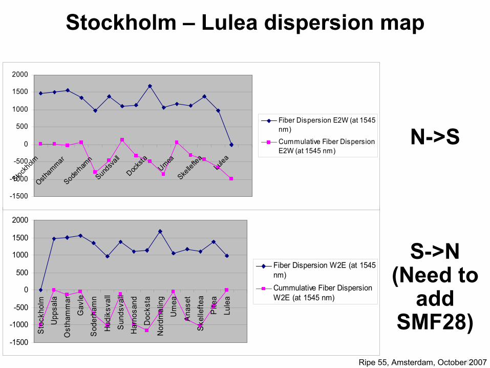
Lulea
BBQ: But that’s only 400Km...
OK, let’s make it longer..
Stockholm – Lulea
SMF28 fiber lenght is 1090Positivie PMD compensation is 46kmPMD N->S is 0.905ps+1.5ps=2.4ps PMD S->N is 1.655ps+1.5ps=3.15psTotal 1090909M + 46000M = 1136909MEDFA’s in System 15COADM’s in System 4Stockholm->Lulea Extra EDFA 1

59Ripe 55, Amsterdam, October 2007
Lulea is 1000KM away... (total project 2800Km drive)

60Ripe 55, Amsterdam, October 2007
MotherNet

61Ripe 55, Amsterdam, October 2007
62Ripe 55, Amsterdam, October 2007
-1500
-1000
-500
0
500
1000
1500
2000
Sto
ckho
lmU
ppsa
laO
stha
mm
ar
Gav
leS
oder
ham
n
Hud
iksv
all
Sun
dsva
llH
arno
sand
Doc
ksta
Nor
dmal
ing
Um
ea
Ana
set
Ske
llefte
aP
itea
Lule
a
Fiber Dispersion W2E (at 1545nm)Cummulative Fiber DispersionW2E (at 1545 nm)
-1500
-1000
-500
0
500
1000
1500
2000
Stockholm
Osthammar
Soderham
nSund
svall
Docks
ta
UmeaSke
llefte
a
Lulea
Fiber Dispersion E2W (at 1545nm)
Cummulative Fiber DispersionE2W (at 1545 nm)
Stockholm – Lulea dispersion map
N->S
S->N(Need to
add SMF28)

63Ripe 55, Amsterdam, October 2007
MotherNet

64Ripe 55, Amsterdam, October 2007
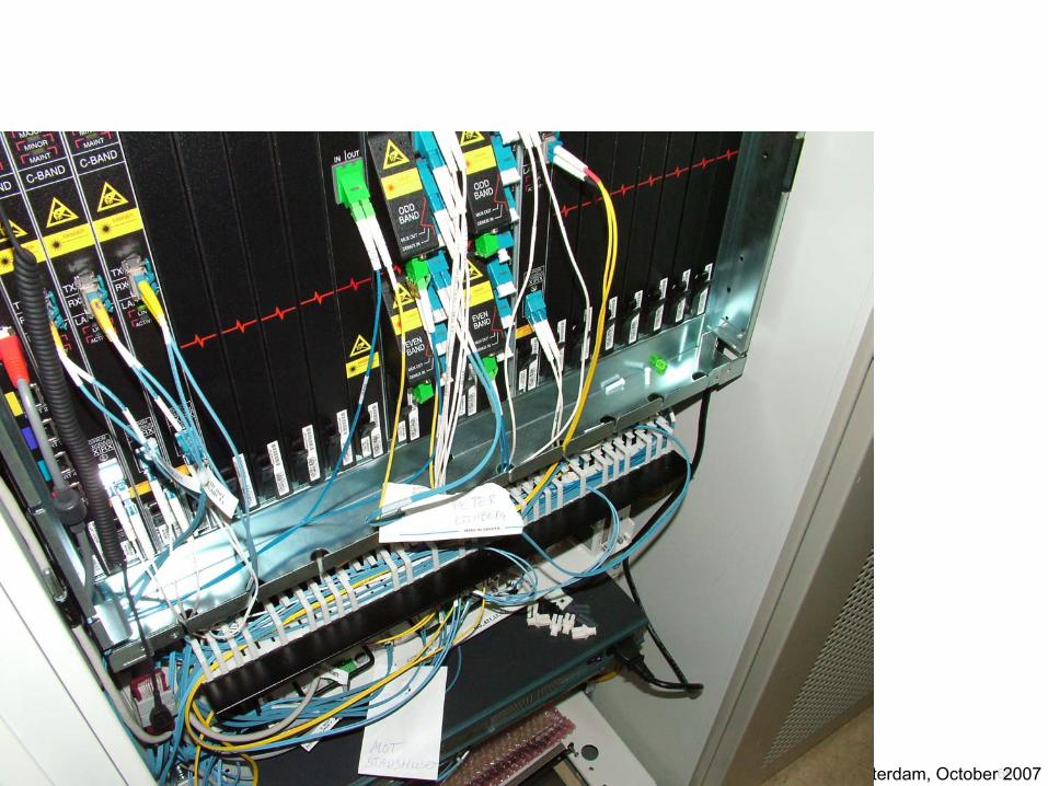
CRS1 and DCMin Stockholm
(Peter Style Instrall)
65Ripe 55, Amsterdam, October 2007

66Ripe 55, Amsterdam, October 2007

67Ripe 55, Amsterdam, October 2007
MotherNet
OK, ENOUGH!
Questions?