firefly aerospace payload user's guide 2019-08-30
TRANSCRIPT

’
Firefly is dedicated to providing customers with economical, reliable, and convenient access to
space. We accomplish this through the design, manufacture, and operation of launch vehicles incorporating
the best of New Space practices and Heritage Space principles.
We employ a collaborative method to mission management and mission assurance. This means
you will receive candid insight into key technical milestones and schedule status. Customers have the option
of even greater insight into Firefly’s engineering rigor for their most critical missions. Our launch vehicle
designs, testing approach, and the quality systems supporting our engineering processes are robust and
transparent to you.
As a customer, you will be provided a dedicated Mission Manager whose priority is ensuring
excellent customer service and support throughout your mission’s campaign. Our team possesses exemplary
industry heritage and expertise, having several decades of experience in both government and commercial
launch programs, At Firefly, we recognize the importance of delivering your spacecraft to orbit reliably, on
time, and at the lowest possible cost. Whether your mission is for a commercial on-orbit capability, scientific
Earth observation, interplanetary exploration, or National Security, we are committed to meeting your needs.
We welcome you to explore the capabilities of the Alpha launch vehicle within this Payload User’s
Guide. For questions regarding Firefly’s other launch and in-space capabilities, please contact the Firefly
Business Development team.
Sincerely,
Shea Ferring
Vice President of Mission Assurance

This user’s guide provides a capability summary for preliminary mission planning. The contents are
not mission specific and are intended to facilitate additional technical interchange between
customers and Firefly mission management personnel. The information in this user’s guide may be
superseded by mission specific documentation provided by Firefly Aerospace, Inc (“Firefly”). Upon
establishing a Launch Service Agreement, we encourage customers provide payload specific
information.
Please contact us with inquiries of Firefly and it’s launch vehicles for your mission.
Firefly Aerospace, Inc.
1320 Arrow Point Drive
Suite 109
Cedar Park, TX 78613
Web: www.firefly.com
E-Mail: [email protected]
March 2018 1.0 First Release
August 2019 2.0 Updated Release

Overview
Alpha
Architecture
Performance
Flight Profile
Payload Injection and Separation
Payload Fairing
Payload Accommodation and Interfaces
Mechanical Interfaces and Separation Systems
Alpha Electrical Interfaces
Loads and Environments
Steady State Acceleration
Acoustics
Shock
Random Vibration
Pressure and Venting
Thermal and Cleanliness
Radio Frequency and EMI/EMC
Standard and Non-Standard Services
Payload Processing Flow
Payload Arrival
Payload Encapsulation
Payload Fueling and Checkout Panels
Launch Campaign Timeline
Infrastructure Available for Customers
Customer Deliverables
Mission Management
Safety Requirements
Hazardous Systems and Operations
Waivers
Corporate Headquarters
Production and Test Facilities
Launch Complexes
SLC-2, Vandenberg Air Force Base
SLC-20, Cape Canaveral Air Force Station
Horizontal Integration Facility
Payload Processing Facility
About Firefly
About The Team
Acronyms
List of Figures
List of Tables


Firefly combines five decades of heritage space experience with the passion and innovativeness of
the “New Space” industry. Our competitive, world-class organization is dedicated to serving
customers with an unrivaled launch experience for their mission needs. Our vision is to pair
innovative technologies with proven flight heritage aerospace applications, tailored to a customer
responsive approach.
Though this guide is specific to the Alpha Launch Vehicle (LV), Figure 1 highlights key
characteristics of our family of LVs along with performance to Sun Synchronous Orbit (SSO), Low
Earth Orbit (LEO) and Geo-Transfer Orbit (GTO).
Performance and Key Characteristics of the Alpha and Beta Launch Vehicles
Payload [SSO, 500km] 630 3,000 kg
Max Payload [LEO, 200km] 1,000 4,000 kg
Payload [GTO] N/A 1,000 kg
GLOW 54,120 149,000 kg
Number of Stages 2 2
Total Length 29.75 31 m
Max Diameter 2.2 2.8 m
Structure All Composite All Composite
Oxidizer LOX LOX
Fuel RP-1 RP-1
Max Thrust [Stage 1] 736 / 165.5 2,208 / 496.4 kN / klbf
Max Thrust [Stage 2] 70 / 15.7 163 / 36.6 kN / klbfβ
10 m
20 m
30 m
0 m α

Firefly’s Alpha provides low-cost capabilities for small satellite customers at a price of $15M for
standard commercial launch services. Firefly aspires to design and engineer the Alpha launch
vehicle as the world’s most reliable, responsive, and operationally capable launch option within the
small launch vehicle class. Supported by Firefly’s streamlined approach to mission planning,
integration, and launch, Alpha is a well-rounded choice for commercial, civil, and demanding
national security missions.
Figure 2 shows an Alpha long duration stage 2 test performed at Firefly’s Briggs, Texas test
facility. These tests confirm engineering analyses and ensure all components are properly
validated while operating in a flight-like configuration.
Alpha Stage Test
Examples of increased efficiencies in our processes include:
• Streamlining Coupled Loads Analysis (CLA) and Interface Control Document/Drawings (ICD) to
decrease completion times from months to weeks or days depending on payload complexity
• A “Test-What You-Fly” and “Test-As-You-Fly” approach to ensure mission success.
• Limited use of ordnance to minimize payload exposure to harsh environments
• A vertically integrated corporate and engineering structure to ensure control over key
technologies and subsystems most impacting mission success, including propulsion, composites
manufacturing and mechanisms
Figure 3 highlights the elements comprising the Alpha Launch Vehicle.

Carbon Composite Structure
2.2 m [7.2 ft] Diameter
12.5 m3 [441.4 ft3] of Internal Volume
All Pneumatic Low Shock Fairing Separation
38.81” bolt interface, compatible with 937 clamp-band
Flight Computer
Multi-Band Path Array Antennae
GPS/IMU Navigation
Power Conditioning & Distribution Unit (PCDU)
Solenoid Drive
Data Acquisition Chassis (DAC)
Telemetry Transmitter
Lithium Polymer Batteries
Flight Termination System
Houses Second Stage Engine
Hot Gas Stage Separation
Carbon Composite
Power Conditioning & Distribution Unit (PCDU)
Solenoid Drive
Data Acquisition Chassis (DAC)
Lithium Polymer Batteries
GLOW 54,120 kg [119,314 lbm]
Height 29.75 m [97.6 ft]
Stage 1 Dry Mass- 2,895 kg [6,382 lbm]
Stage 2 Dry Mass- 909 kg [2,006 lbm]
1,000 kg LEO 28.5o, 200 km
850 kg LEO 45o, 500 km
600 kg to 600 km SSO
6 Ports @ 15” bolt interface
All Composite Construction
Design MEOP 80 psi
All Composite Construction
Design MEOP 80 psi
Aluminum Liner
Design MEOP 5500 psi
Lightning 1
Qty Engines: 1
Propellant: LOX/RP-1
Thrust: 70 kN [15.7 klbf] (vac)
Isp: 322.0 seconds (vac)
All Composite Construction
Design MEOP 80 psi
Aluminum Liner
Design MEOP 5500 psi
All Composite Construction
Design MEOP 80 psi
Reaver 1
Qty Engines: 4
Propellant: LOX/RP-1
Thrust: 736 kN [165.5 klbf] (vac)
Isp: 295.6 seconds (vac)
5.2
m [
16
.9 f
t]5
.75
m [
18
.6 f
t]1
8.8
m [
61
.6.1
ft]
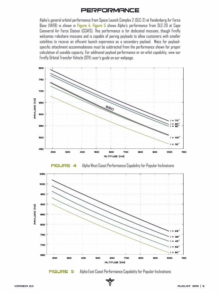
Alpha’s general orbital performance from Space Launch Complex 2 (SLC-2) at Vandenberg Air Force
Base (VAFB) is shown in Figure 4. Figure 5 shows Alpha’s performance from SLC-20 at Cape
Canaveral Air Force Station (CCAFS). This performance is for dedicated missions, though Firefly
welcomes rideshare missions and is capable of pairing payloads to allow customers with smaller
satellites to receive an efficient launch experience as a secondary payload. Mass for payload-
specific attachment accommodations must be subtracted from the performance shown for proper
calculation of useable capacity. For additional payload performance or on-orbit capability, view our
Firefly Orbital Transfer Vehicle (OTV) user’s guide on our webpage.
Alpha West Coast Performance Capability for Popular Inclinations
Alpha East Coast Performance Capability for Popular Inclinations

Alpha Coordinate Frame
The Alpha launch vehicle coordinate frame is depicted in Figure 6 below. The axes definitions are
used throughout the remainder of this document to specify and reference payload environments,
loads, flight, and test requirements. A representative flight profile of the Alpha launch vehicle is
provided in Figure 7. Although missions follow a similar profile, timing and altitude for key events
may vary per mission.
For missions requiring orbits above 400 km, Alpha’s second stage inserts into a low elliptical
transfer orbit, coasts to apogee, and then initiates a second burn maneuver to circularize into the
final desired orbit.

Alpha Direct Insert Flight Profile
Precise pointing and orbit insertion are provided by a
navigation control module consisting of an Inertial
Measurement Unit (IMU) and Global Positioning System (GPS)
receiver on the upper stage of the launch vehicle. The values in
Table 1 represent three-sigma (3) dispersions for a LEO
mission with a second stage Probability of Command Shutdown
(PCS) of 99.7%,
Payload Injection and Separation Accuracy
± 5 km perigee altitude
± 15 km apogee altitude
± 0.1 deg inclination
> 1 ft/sec separation velocity
< 1.4 deg pointing accuracy on each axis
< 1 deg/sec stability in pitch, yaw, and roll
MECO/Stage Separation (T+163 sec)
S1 Jettison
Fairing Jettison
to Orbital Phase
S1 Ignition (T-2 sec)
Liftoff (T-0 sec)
Fairing Separation (T+215 sec) SECO (T+482 sec) S2 Coast & BBQ
Collision Avoidance (T+3500 sec)
Payload
Deployment (T+3400 sec)
S2 Relight &
SECO2(T+3200 sec)
Secondary
Deployment(T+3700 sec)
S2 Ignition (T+168 sec)
ℎ=0 km
𝑣=0 km/s
ℎ=69 km
𝑣=2.92 km/s
ℎ=75 km
𝑣=2.90 km/s
ℎ=116 km
𝑣=3.17 km/s
ℎ=500 km
𝑣=7.96 km/s
ℎ=500 km
𝑣=7.96 km/s
S2 CCAM &
Passivation(T+3800 sec)

The Alpha payload fairing is a carbon composite structure developed, manufactured, and tested by
Firefly, measuring 2.2 m (7.2 ft) in diameter, and 5 m (16.4 ft) in height. The fairing separation
system employs a debris free, low-shock pneumatic separation method fully testable prior to flight.
Figure 8 illustrates the key payload fairing dimensions. The payload fairing remains in place until
launch ascent free molecular heating is below 1,136 W/m2. Immediately thereafter, Alpha initiates a
low shock separation system to deploy the two fairing halves from the payload and LV upper stage.
The payload envelope accounts for dynamic movement of the fairing and payload relative to each
other, acoustic isolation panels, thermal expansion, and manufacturing tolerances. To avoid
coupling with low frequency LV modes and violating this envelope, the SC should be designed to
fundamental frequencies of greater than 8 Hz lateral and 25 Hz axial.
Alpha Payload Fairing Configuration
R2 m
[79”]
1.6 m[63”]
2.5 m[98”]
0.38 m[15”]
937 Compatible0.985 m [38.81”]
5 m[197 in]
R2 m
[79”]
2 m
[79”]
1.6 m
[63 in]

The Alpha vehicle features a standardized 38.81” circular bolt pattern interface which is compatible
with the industry standard 937 adapter and other Firefly-specific dispenser structures. Firefly can
accommodate all industry standard interfaces and separation systems currently flight proven,
depending on customer needs. Accommodations outside the standard bolt pattern may be
negotiated and should be discussed early in the mission planning process. At customer request,
Firefly may procure the separation system desired. Figure 9 illustrates primary payload interface
dimensions within the launch vehicle coordinate frame. Also depicted are allowable payload mass
and CG in relation to the standard interface.
Payload Interface Dimensions in Launch Vehicle Coordinate Frame and Allowable CG Height

Payload Attach Fitting Configurations
Firefly is developing several standardized in-house payload dispensers to accommodate the full
array of small satellites from cube-sats to micro-sats, to ESPA class satellites and larger. Although
each dispenser is compatible with industry standard separation systems, Firefly maintains the
capability to design customized adapters to support unique mission needs. Figure 10 illustrates
some of the common payload configurations and dispensers for the Alpha launch vehicle. Please
contact Firefly for additional information regarding customized payload accommodations.

Alpha Standard Electrical Interface for Primary Payloads
One or two separating connector(s), totaling 30 pins
Ground connectors for EGSE room, TEL and LV interfaces
Seven 20 AWG twisted shielded pairs suitable for RS-
422 serial and ethernet communication
Four 16 AWG twisted shielded pairs suitable for
payload battery charging
Two separation loops for SC to detect separation
Two separation loops for LV to detect separation
Four redundant 28 VDC separation commands:
• 5 amps each
• Minimum pulse of 35ms up to 500ms
• Up to 4 signals simultaneously within 10ms
• Inhibits in accordance with AFSPCMAN 91-710
Figure 11 depicts Alpha’s standard electrical interface for the primary payload. This interface is
compatible with all industry standard separation systems and most spacecraft customer needs.
Additional electrical interface options are available based on customer mission unique needs.

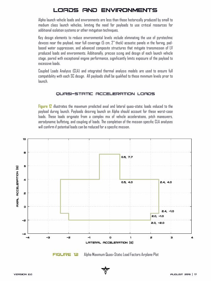
Alpha launch vehicle loads and environments are less than those historically produced by small to
medium class launch vehicles, limiting the need for payloads to use critical resources for
additional isolation systems or other mitigation techniques.
Key design elements to reduce environmental levels include eliminating the use of pyrotechnic
devices near the payload, near full coverage (5 cm, 2” thick) acoustic panels in the fairing, pad-
based water suppression, and advanced composite structures that mitigate transmission of LV
produced loads and environments. Additionally, precise sizing and design of each launch vehicle
stage, paired with exceptional engine performance, significantly limits exposure of the payload to
excessive loads.
Coupled Loads Analysis (CLA) and integrated thermal analysis models are used to ensure full
compatibility with each SC design. All payloads shall be qualified to these minimum levels prior to
launch.
Alpha Maximum Quasi-Static Load Factors Airplane Plot
Figure 12 illustrates the maximum predicted axial and lateral quasi-static loads induced to the
payload during launch. Payloads desiring launch on Alpha should account for these worst-case
loads. These loads originate from a complex mix of vehicle accelerations, pitch maneuvers,
aerodynamic buffeting, and coupling of loads. The completion of the mission specific CLA analyses
will confirm if potential loads can be reduced for a specific mission.
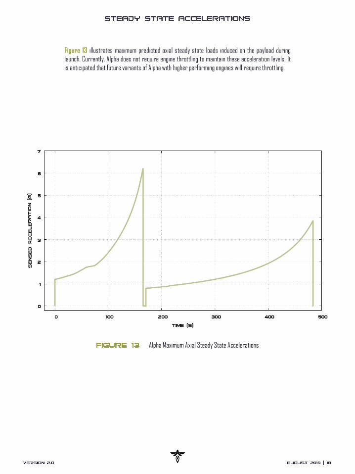
Alpha Maximum Axial Steady State Accelerations
Figure 13 illustrates maximum predicted axial steady state loads induced on the payload during
launch. Currently, Alpha does not require engine throttling to maintain these acceleration levels. It
is anticipated that future variants of Alpha with higher performing engines will require throttling.

Alpha Maximum Predicted Acoustic Environment
Alpha launch vehicle acoustic protection is intended to provide an Overall Sound Pressure Level
(OASPL) well below 139 dB. Currently predicted sound pressure levels within the Payload Fairing
(PLF) and insulative foam are well below this value without the use of water deluge. VAFB’s SLC-2
deluge system will further reduce predicted values. Figure 14 depicts the maximum predicted
acoustic environment of the Alpha launch vehicle without water suppression.
OASPL < 139 dB

The maximum shock environment at the payload interface occurs during payload separation from
the vehicle’s second stage and is dependent on the PAF/Payload Separation System configuration.
Shock levels at the payload separation interface due to stage separation, engine ignition and cutoff,
and payload fairing separation are all maintained below a maximum acceleration of 1,000 g’s at
1000 Hz. Figure 15 and Table 2 below depict the Alpha launch vehicle shock environment, but do
not include the mission specific payload separation system.
Alpha Maximum Predicted Shock Environment
Alpha Frequency and Acceleration Levels
100 HZ 30
100 - 1,000 HZ SEE FIGURE
1,000-10,000 HZ 1,000

Payloads are subjected to a combination of engine vibrations, vehicle structural modes, acoustics,
and aerodynamic forces transmitted through the launch vehicle and into the spacecraft interface.
The intensity of these vibrations is highly dependent on the payload mass, stiffness, and the
interface between the payload and the launch vehicle. The predicted maximum random vibration
PSD for a payload mass of 90 kg or greater, is shown in Figure 16 and Table 3. Test levels per the
GSFC-STD-7000A General Environmental Verification Standard (GEVS) are additionally displayed for
comparison.
Alpha Random Vibration Frequency and PSD Levels
Alpha Random Vibration Environment Plot
20 HZ 0.003
20 – 100 HZ SEE FIGURE
100 – 700 HZ 0.02
700 – 2,000 HZ SEE FIGURE
2,000 HZ 0.003
GRMS 4.9 G

The Alpha launch vehicle is designed to minimize rapid pressure drops within the payload fairing
during ascent. During ascent, the fairing will relieve internal pressure through one-way vents
located at the aft end of the payload fairing. The pressure decay rate will not exceed -0.3
psi/second, except for a brief period during transonic flight, when the decay rate is not expected to
exceed -0.9 psi/second (not depicted in the plot). Figure 17 depicts a typical payload pressure and
venting environment for the Alpha launch vehicle.
Alpha Payload Fairing Venting Environment
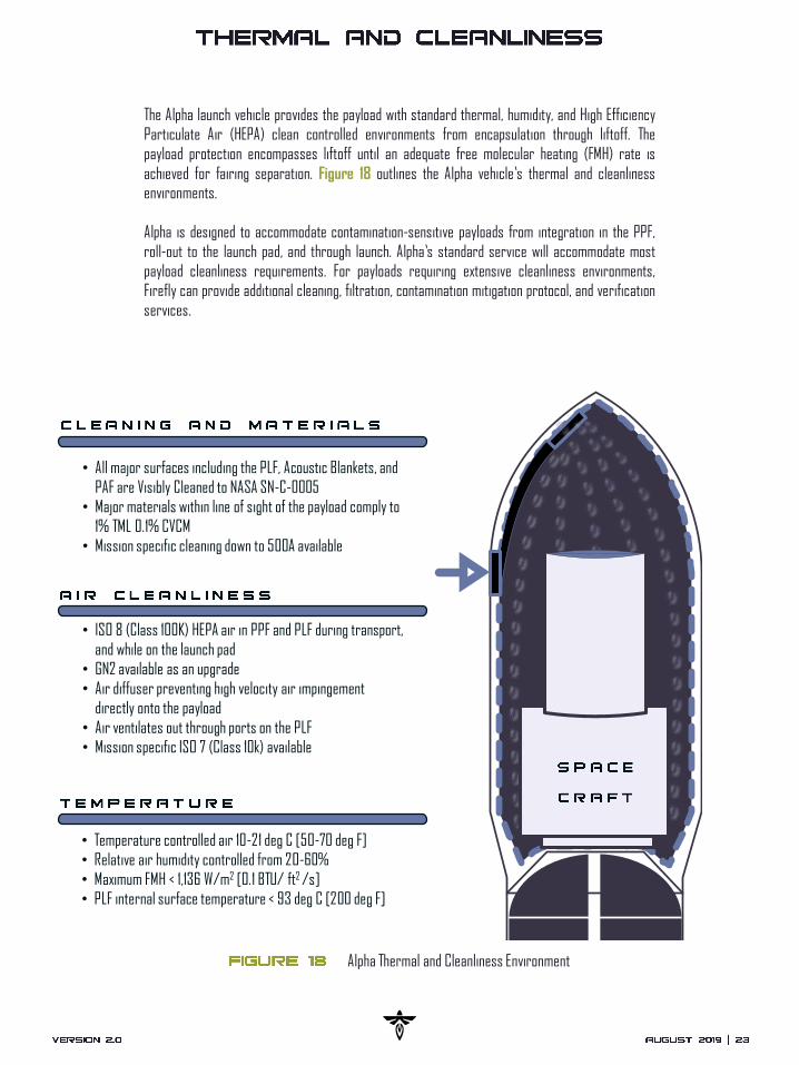
The Alpha launch vehicle provides the payload with standard thermal, humidity, and High Efficiency
Particulate Air (HEPA) clean controlled environments from encapsulation through liftoff. The
payload protection encompasses liftoff until an adequate free molecular heating (FMH) rate is
achieved for fairing separation. Figure 18 outlines the Alpha vehicle’s thermal and cleanliness
environments.
Alpha is designed to accommodate contamination-sensitive payloads from integration in the PPF,
roll-out to the launch pad, and through launch. Alpha’s standard service will accommodate most
payload cleanliness requirements. For payloads requiring extensive cleanliness environments,
Firefly can provide additional cleaning, filtration, contamination mitigation protocol, and verification
services.
Alpha Thermal and Cleanliness Environment
• ISO 8 (Class 100K) HEPA air in PPF and PLF during
transport, and while on the launch pad
• GN2 available as an upgrade
• Air diffuser preventing high velocity air impingement
directly onto the payload
• Air ventilates out through ports on the PLF
• Mission specific ISO 7 available
• Temperature controlled air 10-21 deg C [50-70 deg F]
• Relative humidity controlled from 20-60%
• Maximum FMH < 1,135 W/m2 [0.1 BTU/ ft2 /s]
• PLF internal surface temperature < 93 deg C [200 deg F]
• Temperature controlled air 10-21 deg C [50-70 deg F]
• Relative air humidity controlled from 20-60%
• Maximum FMH < 1,136 W/m2 [0.1 BTU/ ft2 /s]
• PLF internal surface temperature < 93 deg C [200 deg F]
• ISO 8 (Class 100K) HEPA air in PPF and PLF during transport,
and while on the launch pad
• GN2 available as an upgrade
• Air diffuser preventing high velocity air impingement
directly onto the payload
• Air ventilates out through ports on the PLF
• Mission specific ISO 7 (Class 10k) available
• All major surfaces including the PLF, Acoustic Blankets, and
PAF are Visibly Cleaned to NASA SN-C-0005
• Major materials within line of sight of the payload comply to
1% TML 0.1% CVCM
• Mission specific cleaning down to 500A available

Alpha can accommodate payloads which are powered on during launch, but for standard operations
it is recommended payloads be powered off during launch to reduce the potential for interference
or damage caused by RF or Electro Magnetic Interference (EMI). Customers must ensure payload
components or material constituents sensitive to RF transmissions are compatible with the radio
frequency and EMI/EMC environment provided in Table 4 below.
Alpha Radio Frequency and EMI/EMC Environment
S-BAND TRANSMITTER 2.2 - 2.4 GHZ
AVIONICS POWER SWITCHING 100 KHZ - 400 KHZ, 440KHZ, 660 KHZ, 960 KHZ
GPS L-BAND RECEIVERL1: 1575.42 MHZ
L2: 1227.60 MHZ
UHF RECEIVER 421 MHZ


Firefly employs a customer-oriented mission management approach by simplifying launch planning
and integration processes. By understanding both the payload and the launch vehicle boundaries,
Firefly can operate in a quick and agile manner, making customer interactions as streamlined as
possible.
Should non-standard services be required, the customer is encouraged to specify these items
during completion of the Payload Questionnaire. This will enable the Mission Manager to deliver
prompt information regarding payload accommodation, as well as adjustments to launch schedule
or cost. Standard and non-standard services offered by Firefly are described below.
• Dedicated Firefly Mission Manager
• Development of a mission-specific Interface Control Document (ICD)
• Launch vehicle licensing, including FAA and Range Safety Documentation
• Preliminary and final modeling and analysis of the integrated mission, including performance analysis, CLA, and thermal modeling
• Fit Check Verification of the Payload to the PAF
• Certified ISO 8 (Class 100K) cleanroom for payload to PAF integration areas, encapsulation, and through launch
• Two working group meetings, one at Firefly facilities, and the second at the launch site
• Mission dress rehearsal for key launch personnel
• Payload access prior to payload fairing closure
• Delivery of the payload into requested orbit
• Access to all other standard features presented in the guide like the electrical interface and fairing volume
• Post-flight launch services, including payload separation confirmation, delivery of the Post-Flight Data Package, Payload
Environment Report, and final orbit configuration
• Separation system provided by Firefly
• Extensive insight into mission assurance processes, designs, test results, and hardware pedigree
• Customized or multi-payload dispenser
• Payload qualification support for regulatory compliance
• Increased cleanliness levels to ISO 7 (Class 10K) cleanroom facilities for the payload and PLF integration spaces
• Additional mission analysis and modeling
• Contamination control analysis
• Payload non-hazardous and hazardous fueling and pressurization accommodations
• Payload access after payload fairing closure
• Dedicated payload GN2 purge, up to T-0
• RF Transmission after payload encapsulation, and before payload separation
• Additional services may be available upon request as coordinated during mission planning and mission contract
negotiations.

The payload arrives at the Payload Processing Facility (PPF) and is lifted from the transportation carrier by lift truck or overhead
crane located within the airlock. The payload is removed from its shipping container using an overhead crane and readied for
checkouts. Once checkouts are complete, combined SC and LV operations begin with mating of the SC to the Payload Attach Fitting
(PAF). Once the payload is fully assembled onto the PAF and any additional services performed, it is then ready for PLF
encapsulation.
Payloads are encapsulated within the payload fairing in a vertical orientation. Once encapsulated, a continuous supply of HEPA
filtered and temperature-controlled air is supplied to the PLF. A diffuser is installed within the payload fairing at the outlet, to
minimize direct airflow impingement upon sensitive components. The encapsulated payload is then rotated to a horizontal
orientation by means of a break-over fixture and mated to the LV. The encapsulated payload will remain in this horizontal,
cantilevered position until the integrated vehicle is rolled to the launch pad and erected to vertical in advance of launch. Payload
transportation and encapsulation processes are illustrated in Figure 19.
Payload Processing Flow

Each Firefly mission follows a standard timeline, beginning with initial customer contact, and ending
with completion of mission delivery. Flexibility is offered for customers needing an expedited
schedule and should be discussed early in the mission planning process to determine an adequate
timeline. All dates provided in Figure 20 below are intended as guidelines, and not firm constraints.
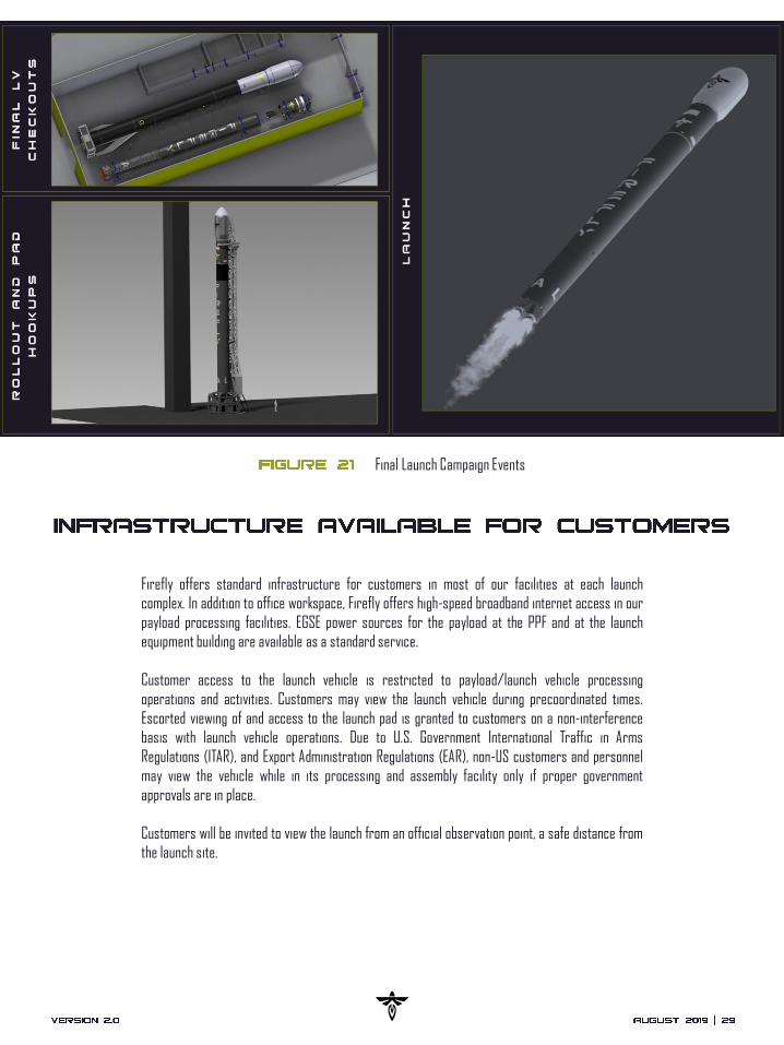
Figure 21 on the next page illustrates key final launch campaign events from vehicle integration
through launch.
Notional Launch Campaign Timeline
Retu
rn o
f all
Cust
omer
Equ
ipm
ent
Initi
al C
usto
mer
Con
tact
and
Com
plet
ion
of th
e Pa
yloa
d Qu
estio
nnai
re
Sign
ing
of L
aunc
h Ag
reem
ent a
nd D
own
Paym
ent
Kick
off W
orki
ng G
roup
and
Del
iver
y of
Pay
load
Dat
a Pa
ckag
e
Fire
fly D
eliv
ery
of P
relim
inar
y M
issi
on A
naly
sis
Mis
sion
Inte
grat
ion
& Gr
ound
Ope
ratio
ns W
orki
ng G
roup
Fit C
heck
(Flig
ht o
r M
ass
Sim
ulat
or)
Fire
fly D
eliv
ers
Fina
l Mis
sion
Ana
lysi
s
Com
men
cem
ent o
f Lau
nch
Cam
paig
n
Deliv
ery
of P
aylo
ad
Laun
ch R
eadi
ness
Rev
iew
Fina
l Con
firm
atio
n of
PL
Sep
and
Stat
e Ve
ctor
Mis
sion
Dat
a Re
view
L-18
m
L-14
m
L-12
m
L-9
m
L-8
m
L-6
m
L-3
m
L-6
w
L-4
w
L-2
d
L+1 h
L+1 w
L+2
m
Launch
As a non-standard option, hazardous, green, and other propellants and pressurization
accommodations may be provided by Firefly. Depending on the type of propellant, these
accommodations may take place at third-party facilities prior to transportation to the launch
complex. Propellant loading details will be coordinated as part of tailored mission support to the
payload.
Firefly offers standard infrastructure for customers in most of our facilities at each launch
complex. In addition to office workspace, Firefly offers high-speed broadband internet access in our
payload processing facilities. EGSE power sources for the payload at the PPF and at the launch
equipment building are available as a standard service.
Customer access to the launch vehicle is restricted to payload/launch vehicle processing
operations and activities. Customers may view the launch vehicle during precoordinated times.
Escorted viewing of and access to the launch pad is granted to customers on a non-interference
basis with launch vehicle operations. Due to U.S. Government International Traffic in Arms
Regulations (ITAR), and Export Administration Regulations (EAR), non-US customers and personnel
may view the vehicle while in its processing and assembly facility only if proper government
approvals are in place.
Customers will be invited to view the launch from an official observation point, a safe distance from
the launch site.
Final Launch Campaign Events


Primary and secondary payload customers are expected to deliver required documentation
pertaining to mission requirements, payload specifications, safety, and payload processing. These
items include, but are not limited to, the deliverables shown in Table 5.
Comprehensive Data Package
Customer Deliverables
An important first step for mission planning includes the
completion of Firefly’s Payload Questionnaire. This will be
provided by your Mission Manager and gives necessary
insight into your mission’s requirements.
Safety documentation and data to support range safety
operations and launch planning are requested early in the
mission planning process. It is the customer’s responsibility
to supply all design, qualification, and acceptance test
information for all hazardous and safety critical elements of
payload subsystems and payload operations.
Customers are expected to complete inputs to the Missile
System Prelaunch Safety Package (MSPSP) using the
template provided by Firefly. Your Firefly Mission Manager
will integrate this information into both the Federal Aviation
Administration (FAA) licensing application and the Range
Safety Review Package.
The Engineering Data Package includes, but is not limited to:
• CAD (inclusive of separation systems and appendages)
• FEA models and a Craig Bampton model for use in CLA
• Mass Properties Report
• Payload Analysis and Test Report
Any requests to operate outside of standard environmental
parameters specified herein must be included.
A detailed Payload Processing Plan including any requests
for non-standard services pertaining to payload processing
and launch operations.
A mass model of the payload is to be provided by the
customer for fit checks. Mass models should show interfaces
representative to flying on Alpha.

Each customer will be assigned a Firefly Mission Manager (FMM), who will remain the direct point-
of-contact throughout the mission planning and launch process. The FMM works closely with their
customer counterpart mission manager, ensuring all facets of the mission planning and integration
process are completed in a timely manner. In addition to ensuring a seamless integration process
to the launch vehicle, the FMM is also the key interface to both the Facility Manager and range
safety. The Facility Manager interface is related to accommodating SC needs at launch site
facilities. The Chief Range Safety Officer interface is for ensuring compliance to all ground and
flight safety requirements. Customers can expect candid transparency and open communication
from their FMM. Maintaining customer satisfaction and delivering an unrivaled customer experience
is part of what sets Firefly apart in an evolving launch market. Figure 22 outlines Firefly’s basic
mission management interface structure.
Mission Services Organizational Structure
Customer
Mission ManagerProgram Management,
Engineering, Operations,
Safety, Quality & Mission Assurance
Firefly Mission ManagerProgram Management,
LV Performance, Interfaces, Accommodations,
Combined Operations, Safety, Quality & Mission
Assurance
Facility ManagerContracting, Scheduling,
Safety, Cleanliness
Interfaces, and
Commodities
Range Chief Safety
OfficerEnvironmental,
Ground, &
Flight Safety

Safety is paramount in the mission planning and launch process. The customer’s Mission Manager,
along with the Mission Assurance team, will ensure payloads meet all safety requirements
throughout the design and launch planning process. Firefly will serve as a direct liaison between all
customers and range safety officials.
It is mandatory for customers to be in compliance with applicable AFSPCMAN 91-710 requirements,
as well as FAA 14 CFR, Part 400 for payload development, including the design of both flight and
ground systems. Customers are responsible for providing inputs to the Firefly MSPSP during early
stages of mission planning as part of Firefly’s Safety Data Package.
Payloads qualifying as a hazardous system or requiring hazardous operations outside of Firefly’s
Standard Service Package, will require both Firefly and range safety approval prior to performing
the operation or conducting launch. The customer’s payload classification will be determined early
in the mission planning stages, to ensure proper permissions are granted.
In the event systems or operations do not meet safety requirements but are believed to be
acceptable for ground and launch operations, range safety officials may grant a waiver. It is the
policy of both Firefly and range safety that waivers are used as a recourse and are not considered
standard practice.

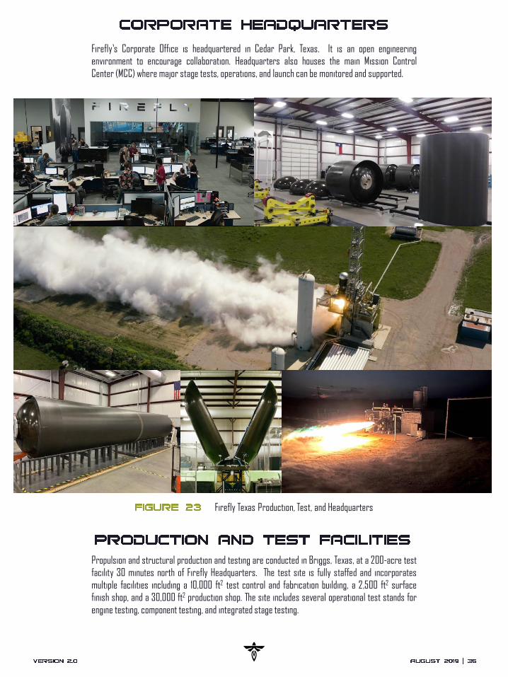
Firefly’s Corporate Office is headquartered in Cedar Park, Texas. It is an open engineering
environment to encourage collaboration. Headquarters also houses the main Mission Control
Center (MCC) where major stage tests, operations, and launch can be monitored and supported.
Firefly Texas Production, Test, and Headquarters
Propulsion and structural production and testing are conducted in Briggs, Texas, at a 200-acre test
facility 30 minutes north of Firefly Headquarters. The test site is fully staffed and incorporates
multiple facilities including a 10,000 ft2 test control and fabrication building, a 2,500 ft2 surface
finish shop, and a 30,000 ft2 production shop. The site includes several operational test stands for
engine testing, component testing, and integrated stage testing.

Firefly launch sites provide customers with a wide range of orbit options to fit mission objectives.
Each facility supports both dedicated and multiple manifest missions.
Firefly conducts Polar and SSO launches to high inclinations from SLC-2 at Vandenberg AFB,
California. Figure 25 shows typical orbit inclinations and launch azimuths from VAFB. Other orbit
inclinations may be possible, inquire with Firefly for additional details.
Vandenberg Air Force Base, SLC-2 Launch Inclinations and Azimuths
Allowable
Orbital Inclination [deg]
Launch Azimuth [deg] 201
104
180
8771
160
140
56
30
124
32
34
36
38
122 120 118 116

SLC-20 is an established launch complex located at Cape Canaveral Air Force Station (CCAFS)
Florida. Launches capable of achieving inclinations from 29 deg to 57 deg are possible from this
site. Figure 26 illustrates orbit inclinations and launch azimuths from CCAFS.
Cape Canaveral Air Force Station, SLC-20 Launch Inclinations and Azimuths
Allowable
Orbital Inclination [deg]
Launch Azimuth [deg]
35
57
70
34
29 90
120
39
24
84
26
28
30
32
82 80 78 76

An on-site horizontal integration facility (HIF) is being utilized for processing and integration of
Firefly launch vehicle stages. The HIF is also where the integrated PLF will be mated to the LV. The
HIF is climate controlled and provides power and high-pressure gases used for processing Alpha
LVs. The HIF is a 5,000 ft2 open high bay, with an eave height of 25 feet, allowing for removal of
Alpha components from shipping fixtures located on flatbed transportation trailers with deck
heights up to 58”. Two bridge cranes in the high bay support processing and operations. Multiple
engineering workstations, administrative space, and communications equipment rooms are
provided.
VAFB Horizontal Integration Facility

The PPF provides controlled environmental space and equipment for payload processing and
encapsulation with a high bay, an airlock, a garment room, and office space.
The PPF high bay is a climate-controlled ISO 8 (Class 100K) cleanroom. Ancillary rooms will be
visibly clean, air conditioned, humidity-controlled workspaces.
Available power consists of 120/240 V single phase 60 Hz, 208 V three phase 60 Hz, and 240/480 V
three phase 60 Hz for processing. Shop air is also available. Additional power and gasses can be
made available on a mission unique basis.
VAFB Payload Processing Facility


Firefly was founded to provide economical and reliable access to space for small payloads through
the design, manufacture, and operation of launch vehicles and spacecraft for the nation’s small
launch market.
To reduce risk and increase reliability, each vehicle is engineered with cross-industry design
insights, leveraging high maturity COTS components. We use a highly vertically integrated
manufacturing process. Propulsion, structures and avionics are designed, built, and tested in-
house, integrating COTS components as required. The technologies employed in our Alpha flagship
vehicle provide a clear pathway for future incremental improvements in capability.
Our engineering team is comprised of established industry leaders with experience in building
launch vehicles, spacecraft, and successful technology organizations, augmented by a passionate
team from the country’s top engineering universities.
With over 230 aerospace professionals on staff, we have a highly technical and capable workforce,
providing Firefly with a balanced culture that blends the best elements of New Space passion, with
heritage space rigor.
Some of The Firefly Team Enjoying an Engine Test!


Air Force Space Command Manual
Autonomous Flight Termination System
Autonomous Flight Termination Unit
Avionics
American Wire Gauge
Command and Data Handling
Computer Aided Design
Cape Canaveral Air Force Station
Cubic Feet per Minute
Coupled Loads Analysis
Commercial-Off-The-Shelf
Center of Gravity
Collected Volatile Condensable Materials
Export Administration Regulations
Electrical, Electronic and Electromechanical
Electrical Ground Support Equipment
Electromagnetic Compatibility
Electromagnetic Interference
Electrical Power System
Evolved Expendable Launch Vehicle
(EELV) Secondary Payload Adapter
Federal Aviation Administration
Finite Element Analysis
Federal Standard
Flight Readiness Review
Frames Per Second
Gross Lift-Off Weight
Gaseous Nitrogen
Guidance, Navigation and Control
Global Positioning System
Gravity Root Mean Square Acceleration
Ground Support Equipment
Graphical User Interface
High Efficiency Particulate Air
Horizontal Integration Facility
Interface Control Document
International Organization for Standardization
Specific Impulse
International Traffic in Arms Regulations
Low-Earth Orbit
Launch Readiness Review
Launch Operations Command Control
Liquid Oxygen
Launch Vehicle
Mission Control Center
Main Engine Cut-Off
Military Standard
Motorized Lightband
Mission Readiness Review
Missile System Prelaunch Safety Package
Overall Sound Pressure Level
Payload Attach Fitting
Probability of Command Shutdown
Payload Fairing
Payload Processing Facility
Payload Segment
Power Spectral Density
Quadrature Phase Shift Keying
Range Commander Council
Radio Frequency
Kerosene
Spacecraft
Second Engine Cut-Off
Space Launch Complex 2
Space Launch Complex 20
Space and Missile Systems Center
Shock Response System
Sun-Synchronous Orbit
To Be Confirmed
To Be Determined
Total Mass Loss
Technology Readiness LevelVandenberg Air Force Base

Key Characteristics of the Alpha and Beta LVs
Alpha Stage Test
Alpha Architecture
Alpha West Coast Performance Capability for Popular Inclinations
Alpha East Coast Performance Capability for Popular Inclinations
Alpha Coordinate Frame
Alpha Direct Insert Profile
Alpha Payload Fairing Configuration
Payload Interface Dimensions in Launch Vehicle Coordinate Frame and Allowable CG Height
Payload Attach Fitting Configurations
Alpha Standard Electrical Interface for Primary Payloads
Alpha Maximum Quasi-Static Load Factors Airplane Plot
Alpha Maximum Axial Steady State Accelerations
Alpha Maximum Predicted Acoustic Environment
Alpha Maximum Predicted Shock Environment
Alpha Random Vibration Environment
Alpha Payload Fairing Venting Environment
Alpha Thermal and Cleanliness Environment
Payload Processing Flow
Notional Launch Campaign Timeline
Final Launch Campaign Events
Mission Services Organizational Structure
Firefly Cedar Park Headquarters, Production, and Test Facilities
Vandenberg Air Force Base, SLC-2 Launch Inclinations and Azimuths
Cape Canaveral Air Force Station, SLC-20 Launch Inclinations and Azimuths
VAFB Horizontal Integration Facility
VAFB Payload Processing Facility
Some of The Firefly Team Enjoying an Engine Test!
Payload Injection and Separation Accuracy
Alpha Frequency and Acceleration Levels
Alpha Frequency and PSD Levels
Alpha Radio Frequency and EMI/EMC Environment
Customer Deliverables
