fire tests on industrial building - fsv Čvut -- people
TRANSCRIPT
1 INTRODUCTION The tests of separate structural elements, e.g. beams, columns, and joints in furnaces allowed to prepare the prediction design models of elements, see (Buchanan, 2003). The main aim of the fire test at structure of the Ammoniac Separator II in company Mittal Steel Ostrava, see Figure 1, was to learn more about the connection temperatures and the internal forces into structure. The behaviour of restrained beams during compartment fire at elevated temperatures, the heating of external element as well as column during local fire and the temperature of sandwich panels, light timber based panels and timber concrete element was studied under the heating by natural fire as well.
Simplified design of structure in fire is based on the design of structure at ambient temperature. The advanced design takes into account the structure loaded by a realistic temperature fire curve and the joints are exposed to forces caused by the elongation during the warming and by the contraction during the cooling faze as well which may be evaluated by the natural fire test only, see (Wald, 2006).
Structural elements outside the fire compartment are heated during the fire by radiation from the flames in the openings of the fire compartment only. The amount of heat transferred from the fire is affected by the position against the opening except of the intensity of the fire. The transfer of heat
outside the fire compartment may be modelled by FEM or by energy based analytical prediction models on more levels of sophistication, see (Wang, 2002). The analytical prediction is based on the gas temperature in the window, which may be evaluated by fluid dynamic models (CFD), zone models, by parametrical curves, or nominal ones with an asked accuracy. The presented work concludes, that the good prediction of the gas temperature by parametric fire curve enable to estimate the temperature of the external steelwork with asked accuracy, see (Law, 1987).
2 DESCRIPTION OF THE TEST
2.1 Steel frame The structure for the test is three storey industrial building attached to single storey framed building, see Figure 1 (Kallerová & Wald, 2006). The load-bearing structure consists of steel columns and beams supporting concrete slab thickness 130 mm, including the ribs. No shear connection between steel beams and the slab was installed. The beam-to-column and beam-to-beam connections are designed as simple end plate connections using two or six bolts M20, see Figure 2.
Fire tests on industrial building
F. Wald, M. Pultar & J. Chlouba Czech Technical University, Prague, Czech Republic
ABSTRACT: The paper presents the results of the fire test on an industrial building before demolition in steel plant in city Ostrava and its comparisons to Eurocode 3 design models. Two fire tests were performed; local fire and compartment fire. The local fire was concentrated to heating of a column and to the temperature distribution in close structure. The compartment fire was focussed on the temperature distribution into the connections during heating and during cooling of the structure; on the internal forces in columns due to the elongation and shortening of an unprotected floor; on the behaviour of steel beams; on the heating of the unprotected front beam; and on heating of the external beam outside the fire compartment. The models of two timber panels, two timber and concrete composite elements and two sandwich panels were exposed to natural fire in the fire compartment as well. The prediction of the temperature by parametric fire curve and of the development of the temperature in the beams by step by step method show a good accuracy. The model of the transfer of heat into the external element was found conservative compare to the measured temperatures.

2.2 Fire compartment The fire compartment sized 3,80 × 5,95 m height 2,78 m was located on 2nd floor. The walls were made from hollow ceramic bricks except the front wall which was made from light weight concrete. One window of width 2,40 m and height 1,40 m was located in the front wall, see Figure 3.
Figure 1. The building before demolition. The steel columns were partially encased in the walls and only the flange was exposed to fire. During the fire test, the exposed column flanges were protected by fibre-silicate boards. The beams and connections were not protected during the test.
Mechanical load was introduced on the third floor. The total load, including self weight of the structure, was 5,7 kN/m2. Wooden cribs created the fire load, 60 kg/m2 e.g. 1060 MJ/m2, by the compartment fire test, see Figure 4. 170 kg located on area 1 × 1 m was used for the local fire.
871135080
11030
35
35
200120 4040
200120
70
Ceramic tiles, 30 mm
IPN300 IPN180 IPN160
IPN300
2×M20 IPN160
240
3535
P10-70×200
4040
P10-200×210
6×M20
2107070
27055 145
Concrete C20/25, 110 mmConcrete slab, C20/25, 80 + 50 mmTrapezoidal sheet VSŽ 11002, 50 mm
Figure 2. The concrete slab, beam to beam and beam to column connections.
Plan 3300 3000300300
340I180
I180
I180
I160
I160
180
200
I300
4000
1320
1330
1350
A
B
C
D
1 2 3
+6,45
+9,50
+7,52
3 floorrd
2 floornd
Section
2780
1070
1400
310+8,92
Figure 3. Dimensions of the fire compartment.
Figure 4. The fire load for the compartment fire test.
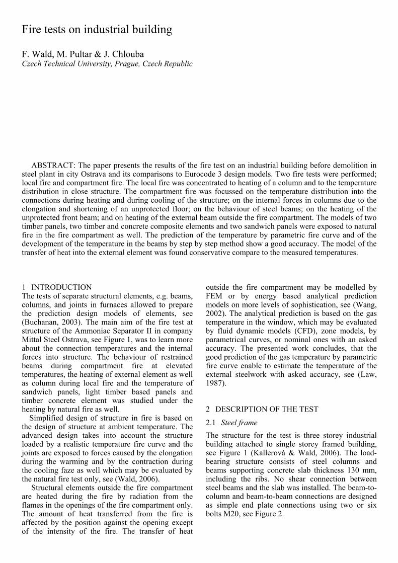
2.3 Measuring devices Thermocouples, strain gauges and displacement transducers recorded the behaviour of the structure during the fire test. In total there were 42 thermocouples to measure the temperature of the air in the fire compartment, of the structural elements and beam connections, see Figure 5. Vertical deformations were measured by five transducers located on third floor at mid-span of the primary and secondary beams. In addition, the relative horizontal displacements of the columns A2-D2, D1-D2 a D2-D3 were observed by three transducers. Strains in the columns were measured by 16 strain gauges attached to the column flanges on first and third floors. The fire and smoke development was recorded by five video cameras and one thermo imaging camera.
500 500
TG1
1000 1000 1000 1000
TG2TG3TG4TG5TG6TC16
TC1
TC2
TC3
TC4
TC5
1 2 3
1 2 3A
B
C
D
A
B
C
D
2000
J1J2
Figure 5. Location of thermocouples on first floor of column D2.
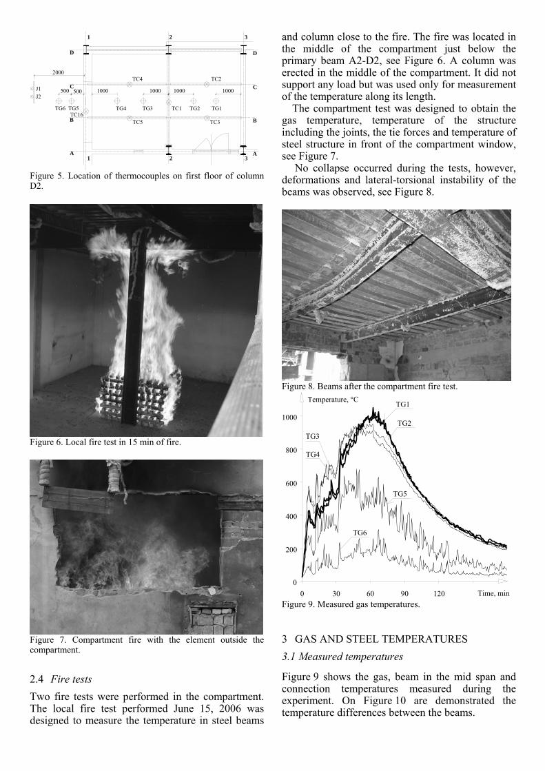
Figure 6. Local fire test in 15 min of fire.
Figure 7. Compartment fire with the element outside the compartment.
2.4 Fire tests Two fire tests were performed in the compartment. The local fire test performed June 15, 2006 was designed to measure the temperature in steel beams
and column close to the fire. The fire was located in the middle of the compartment just below the primary beam A2-D2, see Figure 6. A column was erected in the middle of the compartment. It did not support any load but was used only for measurement of the temperature along its length.
The compartment test was designed to obtain the gas temperature, temperature of the structure including the joints, the tie forces and temperature of steel structure in front of the compartment window, see Figure 7.
No collapse occurred during the tests, however, deformations and lateral-torsional instability of the beams was observed, see Figure 8.
Figure 8. Beams after the compartment fire test.
0
200
400
600
800
1000
0 30 60 90 120
TG1
TG2
TG3
TG4
TG5
TG6
Temperature, °C
Time, min Figure 9. Measured gas temperatures.
3 GAS AND STEEL TEMPERATURES 3.1 Measured temperatures
Figure 9 shows the gas, beam in the mid span and connection temperatures measured during the experiment. On Figure 10 are demonstrated the temperature differences between the beams.
0
200
400
600
800
1000
0 30 60 90 120
TC1
TC2TC3
TC4TC5
TC16
Average gas
Temperature, °C
Time, min
TG1, TG2, TG3, TG4
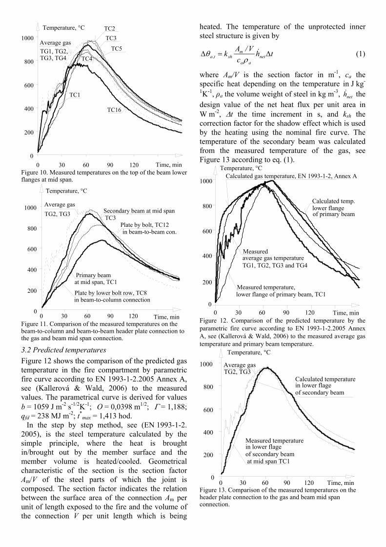
Figure 10. Measured temperatures on the top of the beam lower flanges at mid span.
0
200
400
600
800
1000
0 30 60 90 120
Primary beam
Plate by lower bolt row, TC8
Average gas
Temperature, °C
Time, min
TG2, TG3 Secondary beam at mid span
Plate by bolt, TC12
at mid span, TC1
TC3
in beam-to-beam con.
in beam-to-column connection
Figure 11. Comparison of the measured temperatures on the beam-to-column and beam-to-beam header plate connection to the gas and beam mid span connection.
3.2 Predicted temperatures Figure 12 shows the comparison of the predicted gas temperature in the fire compartment by parametric fire curve according to EN 1993-1-2.2005 Annex A, see (Kallerová & Wald, 2006) to the measured values. The parametrical curve is derived for values b = 1059 J m-2 s-1/2K-1; O = 0,0398 m1/2; Γ = 1,188; qfd = 238 MJ m-2; t*
max = 1,413 hod. In the step by step method, see (EN 1993-1-2. 2005), is the steel temperature calculated by the simple principle, where the heat is brought in/brought out by the member surface and the member volume is heated/cooled. Geometrical characteristic of the section is the section factor Am/V of the steel parts of which the joint is composed. The section factor indicates the relation between the surface area of the connection Am per unit of length exposed to the fire and the volume of the connection V per unit length which is being
heated. The temperature of the unprotected inner steel structure is given by
thc
V/Ak netaa
msht,a Δ=Δ &
ρθ (1)
where Am/V is the section factor in m-1, ca the specific heat depending on the temperature in J kg-
1K-1, ρa the volume weight of steel in kg m-3, neth& the design value of the net heat flux per unit area in W m-2, Δt the time increment in s, and ksh the correction factor for the shadow effect which is used by the heating using the nominal fire curve. The temperature of the secondary beam was calculated from the measured temperature of the gas, see Figure 13 according to eq. (1).
0
200
400
600
800
1000
0 30 60 90 120
Measured temperature,
Calculated temp.
Temperature, °C
lower flange
lower flange of primary beam, TC1
Measuredaverage gas temperature
Calculated gas temperature, EN 1993-1-2, Annex A
of primary beam
TG1, TG2, TG3 and TG4
Time, min Figure 12. Comparison of the predicted temperature by the parametric fire curve according to EN 1993-1-2.2005 Annex A, see (Kallerová & Wald, 2006) to the measured average gas temperature and primary beam temperature.
0
200
400
600
800
1000
0 30 60 90 120
Average gas
Temperature, °C
Time, min
TG2, TG3
in lower flage
at mid span TC1
Measured temperature
of secondary beam
in lower flageCalculated temperature
of secondary beam
Figure 13. Comparison of the measured temperatures on the header plate connection to the gas and beam mid span connection.
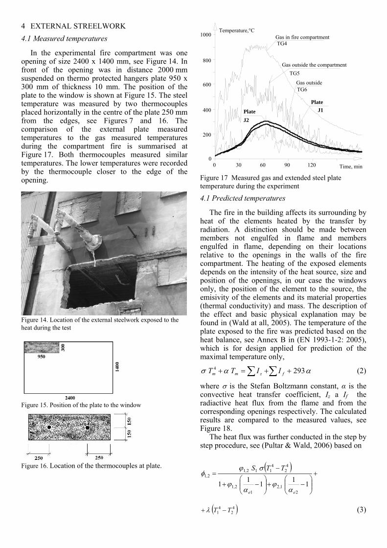
4 EXTERNAL STREELWORK 4.1 Measured temperatures
In the experimental fire compartment was one opening of size 2400 x 1400 mm, see Figure 14. In front of the opening was in distance 2000 mm suspended on thermo protected hangers plate 950 x 300 mm of thickness 10 mm. The position of the plate to the window is shown at Figure 15. The steel temperature was measured by two thermocouples placed horizontally in the centre of the plate 250 mm from the edges, see Figures 7 and 16. The comparison of the external plate measured temperatures to the gas measured temperatures during the compartment fire is summarised at Figure 17. Both thermocouples measured similar temperatures. The lower temperatures were recorded by the thermocouple closer to the edge of the opening.
Figure 14. Location of the external steelwork exposed to the heat during the test
Figure 15. Position of the plate to the window
Figure 16. Location of the thermocouples at plate.
1000
Time, min
Plate
Gas in fire compartmentTemperature,°C
Gas outside the compartment
Gas outside
Plate
0
200
400
600
800
0 30 60 90 120
J1
J2
TG4
TG5
TG6
Figure 17 Measured gas and extended steel plate temperature during the experiment
4.1 Predicted temperatures
The fire in the building affects its surrounding by heat of the elements heated by the transfer by radiation. A distinction should be made between members not engulfed in flame and members engulfed in flame, depending on their locations relative to the openings in the walls of the fire compartment. The heating of the exposed elements depends on the intensity of the heat source, size and position of the openings, in our case the windows only, the position of the element to the source, the emisivity of the elements and its material properties (thermal conductivity) and mass. The description of the effect and basic physical explanation may be found in (Wald at all, 2005). The temperature of the plate exposed to the fire was predicted based on the heat balance, see Annex B in (EN 1993-1-2: 2005), which is for design applied for prediction of the maximal temperature only,
αασ 2934 ∑∑ ++=+ fzmm IITT (2)
where σ is the Stefan Boltzmann constant, α is the convective heat transfer coefficient, Iz a If the radiactive heat flux from the flame and from the corresponding openings respectively. The calculated results are compared to the measured values, see Figure 18.
The heat flux was further conducted in the step by step procedure, see (Pultar & Wald, 2006) based on
( )+
⎟⎟⎠
⎞⎜⎜⎝
⎛−+⎟⎟
⎠
⎞⎜⎜⎝
⎛−+
−=
111112
121
21
42
41121
21
e,
e,
,,
TTS
αϕ
αϕ
σϕφ
( )42
41 TT −+ λ (3)
where index 1 relates to the opening, index 2 to the exposed element, 21,φ is the resultant radiative heat flux,
js, dSj∫= 2
ji21 r
coscosπ
ψψϕ (4)
is the average radiative factor, S1 is the window area, Ti are the temperatures of the flames in the window and exposed element, αei is absorptivity of the flames, is λ the heat transfer coefficient under the cooling of the element of temperature T0. The differential equation derived from eq. (2) for the temperature of the element T2 was solved numerically.
in gas in fire compartment
Temperature,°C
Measured in plate; J1, J2
Predictedin plate
Measured
Time, min0 30 60 90 1200
200
400
600
800
1000
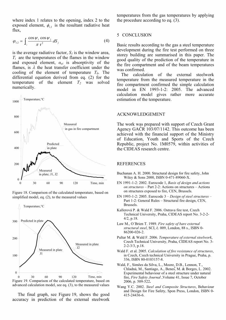
Figure 18. Comparison of the calculated temperature, based on simplified model, eq. (2), to the measured values
Time, min
Measured in plate
Temperature,°C
J1
J2
0
100
200
300
0 30 60 90 120
Predicted in plate
Measured in plate
Figure 19. Comparison of the calculated temperature, based on advanced calculation model, see eq. (3), to the measured values
The final graph, see Figure 19, shows the good
accuracy in prediction of the external steelwork
temperatures from the gas temperatures by applying the procedure according to eq. (3).
5 CONCLUSION
Basic results according to the gas a steel temperature development during the fire test performed on three storey building are summarised in this paper. The good quality of the prediction of the temperature in the fire compartment and of the beam temperatures was confirmed.
The calculation of the external steelwork temperature from the measured temperature in the fire compartment confirmed the simple calculation model in EN 1993-1-2: 2005. The advanced calculation model gives rather more accurate estimation of the temperature.
ACKNOWLEDGEMENT
The work was prepared with support of Czech Grant Agency GAČR 103/07/1142. This outcome has been achieved with the financial support of the Ministry of Education, Youth and Sports of the Czech Republic, project No. 1M0579, within activities of the CIDEAS research centre.
REFERENCES
Buchanan A. H. 2000. Structural design for fire safety, John Wiley & Sons 2000, ISBN 0-471-89060-X.
EN 1991-1-2: 2002. Eurocode 1, Basis of design and actions on structures – Part 2-2: Actions on structures – Actions on structures exposed to fire, CEN, Brussels.
EN 1993-1-2: 2005. Eurocode 3 – Design of steel structures – Part 1-2: General Rules – Structural fire design, CEN, Brussels.
Kallerová P. & Wald F. 2006. Ostrava fire test, Czech Technical University, Praha, CIDEAS report No. 3-2-2-4/2, p.18.
Law M., O´Brien T. 1989. Fire safety of bare external structural steel, SCI, č. 009, London, 88 s., ISBN 0-86200-026-2.
Pultar M. & Wald F. 2006. Temperature of external steelwork, Czech Technical University, Praha, CIDEAS report No. 3-2-2-3/3, p.18.
Wald F. et al. 2005. Calculation of fire resistance of structures, in Czech, Czech technical University in Prague, Praha, p. 336, ISBN 80-0103157-8.
Wald, F., Simões da Silva, L., Moore, D.B., Lennon, T., Chladná, M., Santiago, A., Benes, M. & Borges, L. 2002. Experimental behaviour of a steel structure under natural fire, Fire Safety Journal ,Volume 41, Issue 7, October 2006, p. 509-522.
Wang Y.C. 2002. Steel and Composite Structures, Behaviour and Design for Fire Safety, Spon Press, London, ISBN 0-415-24436-6.