fire resistance assessment - egger · pdf filefire resistance assessment sponsor: egger (uk)...
TRANSCRIPT

The legal validity of this report can only be claimed on presentation of the complete report
Report for: Egger (UK) Ltd. Ref: Chilt/A10187 Revision C
Page 1 of 38
Fire Resistance Assessment
Sponsor:
Egger (UK) Ltd.
Anick Grange Road
Hexham
Northumberland
NE46 4JS
CONFIDENTIAL
Report: Chilt/A10187 Revision C
Contract: CNA/F14148
Egger (UK) Ltd. Eurospan FD60 Doorsets for 60 Minutes Fire Resistance
Issue Date: 11 July 2014
Valid Until: 25 April 2017
Page 1 of 38
This document is confidential and remains the property of Chiltern International Fire Ltd. The legal validity of this report can only be claimed on the
presentation of the complete report.

The legal validity of this report can only be claimed on presentation of the complete report
Report for: Egger (UK) Ltd. Ref: Chilt/A10187 Revision C
Page 2 of 38
BM TRADA – the new name for Chiltern International Fire Ltd.
From July 1st 2013, Chiltern International Fire Ltd. commenced trading under the name of its parent company BM TRADA and at the same time adopted a brand new visual identity.
Historically, the group has delivered its services through a number of individual companies: BM TRADA Certification Ltd, TRADA Technology Ltd, Chiltern International Fire Ltd. (including Chiltern Dynamics) and a network of international offices. Both BM TRADA Group and these individual companies will now trade under the same name - BM TRADA - and adopt the new visual identity.
To coincide with this change, our Technical Reports, Test Reports, Products Assessments, company stationery and marketing collateral have been re-designed to carry the new branding and visual identity.
The validity of all documents previously issued by the individual companies including certificates, test reports and product assessments is unaffected by this change and a letter to this effect will be available to download from our website www.bmtradagroup.com.
About BM TRADA
With origins dating back to 1934, we have a deep history and services which are highly valued by our customers. We offer independent certification, testing, inspection, training and technical services around the world. In all these areas we continue to use industry-leading experts in their chosen fields to develop and deliver services – an ethos that has been at the heart of our approach since we began.
A recent review of our businesses and customers revealed that the individual identities sometimes make communications confusing, and that in an already complex business area, clarity and simplicity in communications is rare, but valued. It also revealed that a single identity and combined offer would help us strengthen our appeal.
With this in mind, we brought the companies together under the name BM TRADA and took the opportunity to create a fresh new visual identity.
We have modernised our image and combined our strengths. However, our values, our people and the integrity of our services remain the same. I hope you will welcome these changes and the improvements they will bring.
Jon Osborn Chief Operating Officer

The legal validity of this report can only be claimed on presentation of the complete report
Report for: Egger (UK) Ltd. Ref: Chilt/A10187 Revision C
Page 3 of 38
Contents Page No.
1 Introduction ...................................................................................................................... 4
2 General Description of Construction ................................................................................ 4
3 Leaf Sizes........................................................................................................................ 4
4 Configurations ................................................................................................................. 4
5 Leaf Size Adjustment ....................................................................................................... 5
6 Overpanels ...................................................................................................................... 5
7 Glazing ............................................................................................................................ 7
8 Door Frames ................................................................................................................. 11
9 Leaf Facing Materials .................................................................................................... 13
10 Lippings ......................................................................................................................... 14
11 Intumescent Materials ................................................................................................... 14
12 Adhesives ...................................................................................................................... 15
13 Hardware ....................................................................................................................... 15
14 Door Gaps ..................................................................................................................... 19
15 Supporting Construction ................................................................................................ 19
16 Fixings ........................................................................................................................... 19
17 Sealing to Structural Opening ........................................................................................ 20
18 Insulation ....................................................................................................................... 21
19 Smoke Control ............................................................................................................... 22
20 Conclusion..................................................................................................................... 22
21 Declaration by the Applicant .......................................................................................... 23
22 Limitations ..................................................................................................................... 24
23 Validity ........................................................................................................................... 24
Appendix A - Performance Data .......................................................................................... 25
Appendix B - Proprietary 60 Minute Glazing Systems .......................................................... 27
Appendix C - Revisions & Amendments............................................................................... 30
Appendix D - Data Sheets ................................................................................................... 31

The legal validity of this report can only be claimed on presentation of the complete report
Report for: Egger (UK) Ltd. Ref: Chilt/A10187 Revision C
Page 4 of 38
1 Introduction
This document constitutes a global assessment relating to Eurospan FD60 fire resisting doorsets, for Egger (UK) Ltd. The assessment uses established extrapolation and interpretation techniques in order to extend the scope of application by determining the limits for the design based on the tested constructions and performances obtained. The assessment is an evaluation of the potential fire resistance performance, if the elements were to be tested in accordance with BS 476: Part 22: 1987.
2 General Description of Construction
The construction for door leaves covered by this assessment comprises the following:
Element Species/type Dimensions (mm) Density (kg/m³)
Stiles & rails None fitted - -
Core Egger Eurospan
FD60 particleboard 38 thick 576
Facings Egger Eurospan
FD60 particleboard 8 thick 666
Adhesive Lipping
Polyurethane - - Core
Lippings Sapele 8 thick 640
3 Leaf Sizes
Assessment for increased leaf dimensions is based on the design’s performance and the characteristics exhibited during test. Data sheets specifying the maximum assessed leaf sizes and graphs showing the permitted gradient between maximum height and width are contained in appendix D.
Unequal leaf double doorsets are covered by this assessment with no restriction on the smaller leaf dimensions. Doorsets containing leaves with smaller dimensions than those stated are deemed to be less onerous and are therefore automatically covered.
4 Configurations
Based on the test evidence listed in appendix A, this assessment covers the following doorset configurations:
Abbreviation Description
LSASD & ULSASD Latched & unlatched, single acting, single doorset
DASD Double acting, single doorset
LSADD & ULSADD Latched & unlatched, single acting, double doorset
DADD Double acting, double doorset

The legal validity of this report can only be claimed on presentation of the complete report
Report for: Egger (UK) Ltd. Ref: Chilt/A10187 Revision C
Page 5 of 38
5 Leaf Size Adjustment
Eurospan FD60 door leaves of this design may be altered as follows:
Element Reduction
Leaf The manufactured size of the leaf may be reduced in height or width without restriction
Timber lippings The dimensions stated in section 10 may be reduced by 20% for fitting purposes
6 Overpanels
6.1 Solid
Overpanels of the same construction as the door leaves may be used only when separated by a transom. The overpanel must be fully contained within the door frame (see following diagram).
The transom must be to the same specification as the door frame.
Door frame joints must utilise one of the following four methods: mortise and tenon joints, half lapped joints, mitre joints or butt joints (see section 8.2).
All methods require joints to be tight, with no gaps, and require mechanical fixing with the appropriate size ring shank nails or screws. Butt joints must be additionally bonded with urea formaldehyde or equivalent.
Overpanels must be fixed by screwing through the rear of the frame with steel screws passing at least 30mm into the centre line of the overpanel. Fixings must be no more than 100mm from each corner and a maximum of 250mm centres in between.
The intumescent seals specified for the jambs in appendix D may be fitted in the overpanel edges or frame reveal; in either case the frame to overpanel junction is permitted to have a maximum 2mm gap tolerance.
Maximum overpanel heights are as follows:
Configuration Max. Overpanel Height (mm)
Single doorsets 2000
Double doorsets 1500
Note: Drawing is representative of doorset construction only; actual construction must be as the text within this document specifies.
Transom
Overpanel fixings
Leaf head
Intumescent seals

The legal validity of this report can only be claimed on presentation of the complete report
Report for: Egger (UK) Ltd. Ref: Chilt/A10187 Revision C
Page 6 of 38
6.2 Glazed Fanlights
Timber frame doorsets including a transom may include a glazed fanlight. The timber frame and glazing beads must be hardwood with a minimum density of 640kg/m3, whilst the frame section for the transom must be a minimum of 70mm x 44mm. Timber door frame and transom construction must comply with the specification contained in section 8.
The maximum assessed fanlight dimensions are detailed in the table below, subject to the following restriction:
The glazing system and glass must be able to demonstrate adequate performance when tested as a window or screen in accordance with BS 476: Part 22: 1987 or BS EN 1634-1, at the pane dimensions to be installed:
Configuration Height (mm) Width (mm)
Single doorsets ≤600 Overall door width
Double doorsets ≤600 Overall door width
Note: Drawing is representative of doorset construction only; actual construction must be as the text within this document specifies.
Assessed glass Bead fixings
Glazing seal
Transom
Leaf head

The legal validity of this report can only be claimed on presentation of the complete report
Report for: Egger (UK) Ltd. Ref: Chilt/A10187 Revision C
Page 7 of 38
7 Glazing
7.1 General
The testing conducted on the Eurospan FD60 doorset design has demonstrated that the design is capable of tolerating large glazed apertures. Based on the dimensions tested, the maximum assessed glazed area for all configurations is 0.85m2.
Glazing must meet the criteria contained in the following sections:
7.2 Assessed Glazing Systems
The maximum assessed glazed area is 0.85m2. The glazing system must be one of the following tested proprietary systems:
Glazing System Manufacturer Max. Area (m2)
1. System 90+ Lorient Polyproducts Ltd. 0.85
2. System 63 (circular apertures only) Lorient Polyproducts Ltd. 0.85
3. System 36/15 Lorient Polyproducts Ltd. 0.85
4. Fireglaze 60 Sealmaster Ltd. 0.85
5. Therm-A-Glaze 60 Intumescent Seals Ltd. 0.85
6. Pyroglaze 601 Mann McGowan Ltd. 0.85
7. FG602 Pyroplex Ltd. 0.42
Note:
1. Pyroglaze 60 must only be used with 60mm long steel screw glazing bead fixings.
2. Pyroplex FG60 must only be used with tested glass and maximum dimensions described in section 7.6 below.

The legal validity of this report can only be claimed on presentation of the complete report
Report for: Egger (UK) Ltd. Ref: Chilt/A10187 Revision C
Page 8 of 38
7.3 Assessed Glass Products
Assessed glass types are as follows:
Glass Type Manufacturer Thickness (mm) Max. Area (m2)
1. Pyroshield Pilkington Group Ltd. 6 & 7 0.85
2. Pyroshield 21 Pilkington Group Ltd. 6 & 7 0.72
3. Pyran S Schott UK Ltd. 6 0.85
4. Pyrostem CGI Ltd. 6 0.85
5. Pyrodur 60-10 Pilkington Group Ltd. 10 0.85
6. Pyroguard EW MAXI CGI Ltd. 11 0.85
7. Pyrobelite 12 AGC Flat Glass UK 12 0.85
8. Pyrodur 60-20 Pilkington Group Ltd. 13 0.85
9. Pyroguard EI30 CGI Ltd. 15 0.85
10. Pyrostop 30-10 Pilklington Group Ltd. 15 0.85
11. Contraflam EI30 Vetrotech Saint-Gobain Ltd. 16 0.85
12. Pyrobel 16 AGC Flat Glass UK 16 0.85
13. Pyroguard EI602 CGI Ltd. 23 0.42
Notes:
1. Pilkington Pyroshield 2 is limited to 0.72m2 and may only be utilised with the tested
glazing system and maximum dimensions described in section 7.5 below.
2. CGI Pyroguard EI60 is limited to 0.42m2 and may only be utilised with the tested glazing
system and maximum dimensions described in section 7.6 below.
3. All glass types must be fitted fully in accordance with the manufacturer’s tested details/installation requirements, particularly with respect to edge cover and expansion clearance.

The legal validity of this report can only be claimed on presentation of the complete report
Report for: Egger (UK) Ltd. Ref: Chilt/A10187 Revision C
Page 9 of 38
7.4 Glazing Beads & Installation
Glazing beads must be from hardwood as specified in the following table:
Material Profile Min. Density (kg/m³) Application
Hardwood Splayed 640 All proprietary systems detailed in section 7.2 and appendix B
Hardwood Square 640 Proprietary systems 4 & 5 as specified in 7.2 and glass types 7 - 12 as specified in 7.3
A square bead profile may be used as an alternative to the splayed beads required for the proprietary systems, subject to the restricted glass types and glazing systems specified in the table above (see appendix B for square bead profile options).
Glazing beads fitted to the door leaves must be hardwood of minimum density 640kg/m3, with a profile appropriate for the glazing system used (see appendix B). The beads must be retained in position using minimum 60mm long x 2mm Ø steel pins, or 60mm long No. 6 - 8 steel screws, inserted at 35 – 40° to the plane of the glass, at no more than 50mm from each corner and at 150mm maximum centres.
Timber for glazing beads must be straight grained, joinery quality hardwood, free from knots, splits and checks.
Aperture shape is not restricted, providing the glazing system and beads are compatible with that shape.
False timber beads must not be applied across the glass face without specific test evidence to justify the system used.
7.5 Pyroshield 2
The following table details the maximum pane sizes and approved glazing systems permitted for Pyroshield 2:
Glass Type Glazing System (see section 7.2)
Max. Pane Size1
(height x width – mm) Max. Area (m
2)
Pyroshield 2 2 1300 x 550 0.72
5 1300 x 310 0.40
Notes:
1. The heights and widths listed are the maximum single dimension allowable for an individual pane utilising the relevant glazing system; maximum dimensions may not be increased even if the other dimension for the pane is reduced.
2. Glazed opening must not be less than 100mm from any door edge. Multiple apertures are acceptable up to the maximum approved area, with a minimum dimension of 80mm between apertures. The aperture shape is not restricted, providing the intumescent material and beads are proven to be compatible with that shape.
3. Glazing beads must be retained in position with 63mm long x 1.8mm diameter steel pins or 60mm long No. 6 – 8 screws, inserted at 35 - 40° to the vertical, at no more than 50mm from each corner and at 150mm maximum centres. Pneumatically fired pins are acceptable providing they meet the specification given above.
4. Timber for glazing beads must be straight grained, joinery quality, free from knots, splits and checks.
5. False timber beads must not be applied across the glass face without specific test evidence to justify the system used.
6. Sectional drawings detailing the tested and approved proprietary glazing systems are contained in appendix B.

The legal validity of this report can only be claimed on presentation of the complete report
Report for: Egger (UK) Ltd. Ref: Chilt/A10187 Revision C
Page 10 of 38
7.6 Pyroguard EI60
The following system must be used with the CGI Ltd. Pyroguard EI60 glass type listed in section 7.3, for glazed apertures up to 0.42m2:
1. Hardwood (min. density 640kg/m3) glazing beads 30mm high by 25mm deep including a
5mm x 5mm bolection return and a 20° chamfer.
2. Beads must be retained in position with 64mm long x 1.8mm diameter steel pins or 60mm long No. 6 – 8 steel screws, fitted at maximum 180mm centres and maximum 50mm from corners.
3. Pyroplex 30096 glazing liner must be fitted lining the glazing aperture.
4. Pyroplex 30095 glazing intumescent must be fitted between the glass and the bead on both faces.
5. The glass must be fitted allowing for 3mm expansion on all edges.
6. An 8mm thick hardwood aperture liner may be fitted, if required.
7. Aperture shape is not restricted, providing the glazing system and beads are compatible with that shape.
8. Timber for glazing beads must be straight grained, joinery quality hardwood, free from knots, splits and checks.
9. Glazed openings must not be less than 145mm from any edge, with a minimum dimension of 145mm between apertures.
10. Multiple apertures are permitted, subject to point 9 above.
11. Sectional drawings detailing the tested and approved proprietary glazing systems are contained in appendix B.

The legal validity of this report can only be claimed on presentation of the complete report
Report for: Egger (UK) Ltd. Ref: Chilt/A10187 Revision C
Page 11 of 38
8 Door Frames
8.1 Door Frame Construction
Door frames must be timber as follows:
Material Section Size (mm) Min. Density (kg/m³)
Hardwood 70 x 32 640
All door frame timber must be straight grained, joinery quality, free from knots, splits and checks.
A 12mm deep planted stop is adequate for single acting frames, whilst double acting frames may be scalloped or square. If frames are square, the maximum radius to the corners of the leaf is 8mm.
Frame joints may be mortice and tenoned, mitred, half lapped or butted and with no gaps (see section 8.2). All jointing methods require mechanical fixing with the appropriate size ring shank nails or screws.
The following diagram depicts the assessed frame profiles and dimensions:
A = min. 70mm B = min. 32mm (see table above) C = min. 12mm
R = radius from floor spring 8mm max. radius to create a maximum 2mm edge profiling
Standard Scalloped Profiled Edges

The legal validity of this report can only be claimed on presentation of the complete report
Report for: Egger (UK) Ltd. Ref: Chilt/A10187 Revision C
Page 12 of 38
8.2 Door Frame Joints
Half Lapped Joint Mitre Joint
Mortice & Tenon Joint Butt Joint
Note: Drawing is representative of each type of door frame joint only; actual construction in terms of intumescent seal location and material, etc. must be as the text within this document specifies.

The legal validity of this report can only be claimed on presentation of the complete report
Report for: Egger (UK) Ltd. Ref: Chilt/A10187 Revision C
Page 13 of 38
8.3 Door Frame Installation
The following diagrams indicate acceptable and unacceptable door frame installations:
6 to 10mm
Max 10 x 10mm shadow gap with 2mm
intumescent mastic capping or
10 x 4mm PVC encased intumescent seal
15mm
Permitted Permitted
PermittedNot PermittedNot Permitted
Permitted
Notes: Drawings are representative of door frame installation only; actual installation must be as the text within this document specifies. See section 18 for specification on sealing to structural opening.
For shadow detail depicted (top right) the sub-frame material must be non-combustible or timber with a minimum density of 640kg/m
3.
9 Leaf Facing Materials
9.1 Primary Facings
The Eurospan FD60 design is produced with integral 8mm thick particleboard facings, therefore alternative materials are not permitted.
9.2 Additional Decorative & Protective Facings
The following additional facing materials are permitted for this door design since they would degrade rapidly under test conditions without significant effect:
Facing Material Max. Permitted Thickness (mm)
Paint 0.5
Timber veneers 2
Plastic laminates 2
PVC 2
Decorative paper/non-metallic foil 0.4
Notes:
1. Metallic facings are not permitted (except for push plates and kick plates).
2. Materials must not conceal intumescent strips.
3. Plastic laminates must not be applied to the edges of leaves.

The legal validity of this report can only be claimed on presentation of the complete report
Report for: Egger (UK) Ltd. Ref: Chilt/A10187 Revision C
Page 14 of 38
10 Lippings
Eurospan FD60 doors require lipping in accordance with the following specification:
Material Size (mm – thick) Min. Density (kg/m3)
Straight grained joinery quality hardwood, free
from knots, splits and checks
1. Flat = 8 – 13 with a maximum 2mm profiling permitted at corners of lipping (see section 8.1).
2. Rounded = 8 – 13 with a radius matching the distance between leaf edge and floor pivot (see section 8.1).
3. Rebated = Not permitted.
640
Notes:
1. Single acting doorsets must be lipped on the vertical edges, and may additionally be lipped on all edges as required.
2. Double acting doorsets must be lipped on all edges.
3. A 2.5° chamfer is permitted to the lipping at the leading edge of leaves providing the door gaps meet the requirements in section 15.
11 Intumescent Materials
The intumescent materials tested and assessed for this doorset design are as follows:
Application Location Product/Manufacturer
Edge seals Fitted in the frame jambs or leaf edges
PVC encased Type 617 – Lorient Polyproducts Ltd.
Pyroplex Rigid Box Seals – Pyroplex Ltd.
Hinges Under both
hinge blades
1mm MAP paper – Lorient Polyproducts Ltd.
1mm Interdens – Lorient Polyproducts Ltd. or Dufaylite Developments Ltd.
1mm Pyrostrip 300 – Mann McGowan Ltd.
1mm Therm-A-Strip – Intumescent Seals Ltd.
Lock/latches Under forend
& keep
1mm MAP paper – Lorient Polyproducts Ltd.
1mm Interdens – Lorient Polyproducts Ltd. or Dufaylite Developments Ltd.
1mm Pyrostrip 300 – Mann McGowan Ltd.
1mm Therm-A-Strip – Intumescent Seals Ltd.
Top pivots & flush bolts
Lining all sides of the
mortices
2mm MAP paper – Lorient Polyproducts Ltd.
2mm Interdens – Lorient Polyproducts Ltd. or Dufaylite Developments Ltd.
2mm Therm-A-Strip – Intumescent Seals Ltd.
2mm Dorma gasket pack – Dorma Door Controls Ltd.
The seal specification for each configuration is shown in appendix D.

The legal validity of this report can only be claimed on presentation of the complete report
Report for: Egger (UK) Ltd. Ref: Chilt/A10187 Revision C
Page 15 of 38
12 Adhesives
The following adhesives must be used in construction:
Element Adhesive
Facings to core Polyurethane
Timber Lippings PVA or Polyurethane
13 Hardware
13.1 General
The following sections detail the permitted scope and constraints for fitting hardware to this door design. The following items of hardware must also bear the CE Mark:
Latches & Locks: Test Standard EN 12209
Single Axis Hinges: Test Standard EN 1935
Controlled Door Closing Devices: Test Standard EN 1154
Electro-Mechanically Operated Locks: Test Standard EN 14846
Electrically Powered Hold-Open Devices: Test Standard EN 1155
Door Co-ordinators: Test Standard EN 1158
Emergency Exit Hardware: Test Standard EN 179
Panic Exit Hardware: Test Standard EN 1125.
13.2 Tested Hardware
The following hardware has been successfully incorporated in the tests on this design:
Element Make/Type Size (mm) Location
Hinges
Royde & Tucker H101 lift-off type
100 x 35 (blade size) Fitted 150mm, 1157mm & 2166mm from head of leaf
Royde & Tucker H105 lift-off type
100 x 35 (blade size) Fitted 150mm, 1017mm and 1857mm from head of leaf
Lock/latch
E*S tubular steel mortise latch
57 x 26 (forend size) Fitted 1000mm from threshold
Arrone tubular steel mortice latch
155 x 22 (forend size) Fitted 1000mm from threshold
155 x 24 (keep size)
Closer
Dorma (UK) Ltd. TS71 overhead type
232 x 68 (footprint size)
Fitted on the exposed face as per the manufacturer’s
instructions
Rutland TS3204 overhead type
220 x 59 (footprint size)
Fitted on the exposed face as per the manufacturer’s
instructions
Dorma (UK) Ltd. BTS 84 floor spring &
adjustable top pivot. Product Ref. 8066
324 x 130 (footprint size)
Fitted in the threshold as per the manufacturer’s instructions
122 x 29 (footprint size)
Fitted in the frame and leaf head as per the
manufacturer’s instructions
Furniture Aluminium lever type
door handle 100 x 38 (footprint
size) Fitted appropriate to the latch

The legal validity of this report can only be claimed on presentation of the complete report
Report for: Egger (UK) Ltd. Ref: Chilt/A10187 Revision C
Page 16 of 38
13.3 Additional & Alternative Hardware
13.3.1 Latches & Locks
Latches and locks must either be as tested, or alternatively components with the following specification are acceptable:
Maximum forend and strike plate dimensions
235mm high by 25mm wide by 4mm thick
Maximum body dimensions 165mm high by 100mm wide by 18mm thick
Intumescent protection See section 11
Materials All parts essential to the locking/latching action (including the latch bolt, forend and strike) to be steel
Location 1000 - 1200mm from the threshold of the leaf
13.3.2 Hinges
Leaves must be hung on a minimum of 3 hinges. Leaves >2400mm (h) must be hung on 4 hinges. Hinges with the following specification are acceptable:
Blade height 90 – 120mm
Blade width (excluding knuckle)
30 – 35mm
Blade thickness 2.5 – 4mm
Fixings Minimum of 4No. 30mm long No. 8 or No. 10 steel wood screws per blade
Materials Steel or stainless steel
Hinge positions
If 3 hinges are required
Top 100 – 180mm from the head to top of hinge
2nd
Minimum 200mm from top hinge or centrally fitted between top and bottom hinge
Bottom 150 – 250mm from the foot of leaf to bottom of hinge
If 4 hinges are required
Top 100 – 180mm from the head to top of hinge
2nd
& 3rd
Equispaced between top and bottom or 2
nd
hinge 200mm from top hinge and 3rd
hinge equally spaced between 2
nd and bottom hinge
Bottom 150 – 250mm from the foot of leaf to bottom of hinge
Intumescent protection See section 11
13.3.3 Automatic Closing
Automatic closing devices must either be as tested or components of equal specification that have demonstrated contribution to the required performance of this type of 60 minute doorset design, when tested to BS 476: Part 22: 1987 or BS EN 1634-1.
Note: The top pivots to floorspring assemblies must be protected with 2mm thick intumescent gaskets (see section 11), or alternatively the manufacturers tested intumescent pack.

The legal validity of this report can only be claimed on presentation of the complete report
Report for: Egger (UK) Ltd. Ref: Chilt/A10187 Revision C
Page 17 of 38
13.3.4 Flush Bolts
Flush bolts may be incorporated centrally into the top and bottom of one meeting edge, providing the following maximum dimensions are not exceeded and the components are fitted opposite the edge fitted with intumescent strips:
200mm long x 20mm deep x 20mm wide
Flush bolts must be steel and the mortice must be as tight to the mechanism as is compatible with its operation. All edges of the mortice must be protected with intumescent gaskets as specified in section 11. Alternatively, the hardware manufacturers tested gaskets may be used.
13.3.5 Pull Handles
These may be surface-fixed to the door leaf provided that they are steel or brass and the length is limited to 1200mm between the fixing points. No additional intumescent protection is required provided that the hole for the bolt through the leaf is tight.
13.3.6 Push Plates/Kick Plates
Face-fixed push plates and kick plates may be fitted to the doorsets provided their fitting requires the removal of no part of the door leaf. These items are permitted up to a maximum 20% of the door leaf area if mechanically fixed and a maximum of 30% if bonded with a contact or thermally softening adhesive and positioned to fall away from the leaf. Plates must not return around the door leaf edges.
13.3.7 Door Selectors
Where required to accommodate latched doorsets, these may be freely applied, provided that they are not invasive in the leaf edges or door frames. Those that are invasive will require fire resistance test/assessment evidence to support their use. No additional intumescent protection is required unless test evidence dictates otherwise.
13.3.8 Door Security Viewers
Door security viewers with brass or steel bodies of a diameter less than or equal to 15mm may be used provided that the through-hole is bored tight to the case of the viewer (maximum tolerance +1mm). Lenses must be glass and the item must be bedded in to a tested intumescent mastic.
Intumescent gaskets
Flush bolt mechanism
Door leaf

The legal validity of this report can only be claimed on presentation of the complete report
Report for: Egger (UK) Ltd. Ref: Chilt/A10187 Revision C
Page 18 of 38
13.3.9 Panic Hardware
Panic hardware may be fitted, provided that its installation does not require the removal of any timber from the leaf, stop or frame reveal and it in no way interferes with the self-closing action of the door leaf.
13.3.10 Environmental Seals
Silicon based flame retardant acoustic, weather and dust seals may be fitted to this doorset design without compromising the performance, providing their fitting does not interfere with the activation of the intumescent seals or hinder the self-closing function of the leaves.
13.3.11 Threshold Seals
The following types of automatic threshold drop seals may be recessed in to the bottom rail of leaves to this design without compromising the performance:
Manufacturer Product
Lorient Polyproducts Ltd. IS8010si
Raven Products Ltd. RP8Si
Athmer Schall-Ex Duo L-15
Norsound Ltd. NOR810, NOR810S, NOR810dB+
13.3.12 Letter Boxes/Plates
Letter boxes/plates may be fitted providing the product has demonstrated contribution to the required integrity performance of this type of doorset design, when tested to BS 476: Part 22: 1987 or BS EN 1634-1, when installed in a timber based doorset of comparable thickness. Products may be fitted up to 1200mm from floor level and no closer than 100mm to any leaf edge.
13.3.13 Air Transfer Grilles
Air transfer grilles may be fitted providing the product has suitable test evidence to BS 476: Part 22: 1987 or BS EN 1634-1, demonstrating a minimum 60 minutes integrity performance when installed within a timber based doorset of comparable thickness. Margins to leaf edges are as detailed for glazing and the position of the unit will be dictated by the pressure regime tested for the grille (normally below mid-height). The area occupied by the grille must not exceed 0.2m2 and must be deducted from the assessed glazing area, if both elements are fitted.
If it is required to fit air transfer grilles outside of the aforementioned scope, guidance and appropriate test evidence must be sought from the manufacturer of the grille, including permitted numbers of grilles, spacing within the door leaf, additional intumescents, aperture liners and location within the doorset (with respect to pressure regime).
Lorient Polyproducts Ltd. manufacture a range of intumescent air transfer grilles with an integral smoke control shutter tested to BS 476: Part 31: Section 31.1.

The legal validity of this report can only be claimed on presentation of the complete report
Report for: Egger (UK) Ltd. Ref: Chilt/A10187 Revision C
Page 19 of 38
13.3.14 Cable-Way
Based on the integrity performance of the doorset construction, with no burn-through of the core material, we consider it acceptable to allow the provision for a concealed cable-way to facilitate electro-magnetic closing/latching mechanisms. The cable-way must be concealed in the following way:
1. A hole drilled centrally though the leaf of maximum 10mm diameter.
2. The cable for the electronic closing/latching mechanism must be no more than 2mm smaller in diameter than the hole through the leaf.
3. The cable for the electronic closing/latching mechanism must be PVC encased.
4. Cable-ways are only permitted for use with latched, single leaf, single acting doorsets with maximum leaf dimensions of 2100mm (h) x 900mm (w).
5. The hole must be located below 1500mm from the threshold and must be spaced a minimum of 90mm from any apertures within the leaf, e.g. glazing, air transfer grilles or letter plates, etc.
This approval is subject to the hardware manufacturer having the appropriate test evidence for the product for use with this type of 60 minute construction. Test evidence generated in steel doorsets is not acceptable. Any tested intumescent gaskets for the lockset, closing mechanism, receiver plate, cable loops, etc. must be replicated.
14 Door Gaps
For fire resisting applications, door edge gaps and alignment tolerances must be set within the range defined in the following table:
Location Dimensions
Door edge gaps A minimum of 2mm and a maximum of 4mm
Alignment tolerances Leaves must not be proud of each other or from the door frame by more than 1mm
Threshold 10mm between bottom of leaf and top of floor covering
15 Supporting Construction
The supporting construction must provide the required level of fire resistance designated for the doorset design and be a suitable medium to permit adequate fixity.
16 Fixings
The frame jambs are to be fixed to the supporting construction using steel fixings at 500mm maximum centres. The fixings must be of the appropriate type for the supporting construction and must penetrate to a minimum depth of 50mm. It is not necessary to fix the frame head, although packers must be inserted.

The legal validity of this report can only be claimed on presentation of the complete report
Report for: Egger (UK) Ltd. Ref: Chilt/A10187 Revision C
Page 20 of 38
17 Sealing to Structural Opening
The door frame to structural opening gap must be protected using one of the following methods:
1. Gaps up to 10mm must be sealed on both sides with a 10mm depth of acrylic intumescent mastic, fire tested for this application to BS 476: Part 22: 1987 or BS EN 1634-1. Joint must be fitted with 15mm thick architraves overlapping at least 15mm each side.
2. Gaps between 10mm and 20mm must be tightly packed with mineral fibre capped on both sides with a 10mm depth of acrylic intumescent mastic, fire tested for this application to BS 476: Part 22: 1987 or BS EN 1634-1. Architraves are optional.
3. Gaps up to 20mm filled with proprietary fire stopping product (e.g. expanding PU foam or preformed compressible intumescent foam). Products must be tested for this application to BS 476: Part 22: 1987 or BS EN 1634-1. Joint must be fitted with 15mm thick architraves overlapping at least 15mm each side.
4. Timber based or non-combustible subframe up to 50mm thick, with no gaps between the components. Joint must be fitted with 15mm thick architraves overlapping at least 15mm each side.
Fire stopping product
Frame fixing Architrave
Timber based or non-combustible subframe
Architrave
Fixing for subframe
Frame fixing
Architrave for joints not filled with mineral wool and optional for filled joints
Frame fixing Mineral fibre infill for joints exceeding 10mm
Acrylic intumescent mastic

The legal validity of this report can only be claimed on presentation of the complete report
Report for: Egger (UK) Ltd. Ref: Chilt/A10187 Revision C
Page 21 of 38
5. Timber based or non-combustible subframe up to 50mm thick, with gaps up to 10mm between the components filled on both sides with 10mm depth of acrylic intumescent mastic or full depth expanding PU foam, fire tested for this application to BS 476: Part 22: 1987 or BS EN 1634-1. Joint must be fitted with 15mm thick architraves overlapping at least 15mm each side.
Guidance for various methods of sealing the frame to structural opening gap is also given in BS 8214: 2008, Code of practice for timber fire doors, which may be referred to where appropriate.
Note: Drawings are representative of doorset installation only; actual installations must be as the text within this document specifies.
18 Insulation
Insulation performance may be claimed for a doorset to this design meeting the following criteria:
Type Details
Partially insulating Doorsets incorporating up to 20% of non-insulating glazing
Fully insulating Unglazed doorsets
15mm thick architrave
10mm of acrylic intumescent mastic or full depth PU foam
Frame fixing
Sub frame fixing

The legal validity of this report can only be claimed on presentation of the complete report
Report for: Egger (UK) Ltd. Ref: Chilt/A10187 Revision C
Page 22 of 38
19 Smoke Control
19.1 General
If the doorset design is required to provide a smoke control function to comply with Building Regulations, the doorset must meet one of the following criteria (unless pressurization techniques complying with BS EN 1201-6 are used):
(a) have a leakage rate not exceeding 3m3/m/hour (head and jambs only) when tested at 25Pa under BS 476 Fire tests on building materials and structures, Section 31.1 - Methods for measuring smoke penetration through doorsets and shutter assemblies, Method of measurement under ambient temperature conditions; or
(b) meet the additional classification requirement of Sa when tested to BS EN 1634-3: 2004 - Fire resistance tests for door and shutter assemblies, Part 3 – Smoke control doors.
Smoke seals or combined intumescent/smoke seals that are fitted to the door to achieve the performance requirements specified above must have been tested in accordance with the associated test method. Providing the smoke seals, any interruptions, door gaps, and the type/configuration of the doorset are consistent with the detail tested, the doorset will comply with current smoke control legislation under Approved Document B, and a suffix ‘S’ or ‘Sa’, as appropriate, may be added to the designation. Any other components installed where smoke leakage may occur must also be taken into account.
Note: The incorrect specification and fitting of smoke seals may impair the operation of a doorset and therefore compromise the fire resistance performance. Advice should be sought from the seal manufacturers regarding the correct specification and installation of smoke seals or combined smoke and intumescent seals.
19.2 Further Considerations
Other guidance is available, including BS EN 9999-2008 - Code of practice for fire safety in the design, management and use of buildings, which may impose different or additional requirements. It is the responsibility of the relevant parties to stipulate the precise smoke control specification, prior to commencing manufacture and/or installation.
20 Conclusion
If the Egger Eurospan FD60 doorsets, constructed in accordance with the specification documented in this global assessment, were to be tested in accordance with BS 476: Part 22: 1987, it is our opinion that they would provide a minimum of 60 minutes integrity and insulation (subject to section 18).

The legal validity of this report can only be claimed on presentation of the complete report
Report for: Egger (UK) Ltd. Ref: Chilt/A10187 Revision C
Page 23 of 38
21 Declaration by the Applicant
1. We the undersigned confirm that we have read and comply with obligations placed on us by FTSG Resolution No. 82: 2001.
2. We confirm that the component or element of structure, which is the subject of this assessment, has not to our knowledge been subjected to a fire test to the Standard against which this assessment is being made.
3. We agree to withdraw this assessment from circulation should the component or element of structure be the subject of a fire test to the Standard against which this assessment is being made.
4. We are not aware of any information that could adversely affect the conclusions of this assessment.
5. If we subsequently become aware of any such information we agree to ask the assessing authority to withdraw the assessment.
Signed:
Name:
For and on behalf of: Egger (UK) Ltd.

The legal validity of this report can only be claimed on presentation of the complete report
Report for: Egger (UK) Ltd. Ref: Chilt/A10187 Revision C
Page 24 of 38
22 Limitations
The following limitations apply to this assessment:
1. This assessment addresses itself solely to the elements and subjects discussed and does not cover any other criteria. All other details not specifically referred to should remain as tested or assessed.
2. This assessment is issued on the basis of test data and information to hand at the time of issue. If contradictory evidence becomes available, BM TRADA reserves the right to withdraw the assessment unconditionally but not retrospectively.
3. This assessment has been carried out in accordance with Fire Test Study Group Resolution No. 82: 2001.
4. Opinions and interpretations expressed herein are outside the scope of UKAS accreditation.
5. This assessment relates only to those aspects of design, materials and construction that influence the performance of the element(s) under fire resistance test conditions. It does not purport to be a complete specification ensuring fitness for purpose and long-term serviceability. It is the responsibility of the client to ensure that the element conforms to recognised good practice in all other respects and that, with the incorporation of the guidance given in this assessment, the element is suitable for its intended purpose.
23 Validity
1. The assessment is initially valid until 25th April 2017 after which time it must be submitted to BM TRADA for technical review.
2. This assessment report is not valid unless it incorporates the declaration given in Section 21 duly signed by the applicant.
Signature:
Name: J Godfrey P N Barker
Title: Product Assessor Principal Technical Officer

The legal validity of this report can only be claimed on presentation of the complete report
Report for: Egger (UK) Ltd. Ref: Chilt/A10187 Revision C
Page 25 of 38
Appendix A
Performance Data
Primary Data
Report Reference
Configuration Leaf Size (mm) Test
Standard Performance
(mins)
RF10047
A: ULSADD 2135 x 915/545 x
54 BS 476: Part
22: 1987
Integrity: 581
Insulation: 581
B: ULSASD 2135 x 915 x 54 BS 476: Part
22: 1987
Integrity: 62
Insulation: 0
RF10104 DADD 2135 x 915/545 x
54 BS 476: Part
22: 1987
Integrity: 75
Insulation: 0
RF10166
A: ULSASD 2446 x 1235 x 54
BS 476: Part 22: 1987
Integrity: 61
Insulation: 61
B: ULSASD 2815 x 927 x 54 Integrity: 562
Insulation: 562
RF12009
A: ULSADD 2135 x 915/545 x
54 BS 476: Part
22: 1987
Integrity: 62
Insulation: 62
B: ULSASD 2815 x 926 x 54 Integrity: 68
Insulation: 68
PF13278 (Pyroplex
edge seals)
A: ULSADD 2130 x 908/534 x
54 BS 476: Part 20/22: 1987
Integrity: 61
Insulation: 61
B: ULSASD 2130 x 895 x 54 BS 476: Part 20/22: 1987
Integrity: 72
Insulation: 72
RF13014 (Pyroplex
FG60 glazing system & Pyroguard EI60 glass)
ULSADD 2300 x 975 x 54 BS 476: Part 20/22: 1987
Integrity: 563
Insulation: 563
Notes:
1. The premature failure at the top hanging corner of the doorset was due to inadequate sealing between the door frame and structural opening during installation. If the sealing had been to the required specification, the doorset would have achieved 61 minutes integrity.
2. Failure on doorset B occurred at the latch position – the latch keep fitted measured 235 x 50mm and fully interrupted both intumescent seals in the frame reveal; although it was bedded onto 1mm thick Interdens. The size of latch keep assessed in section 14.2 is limited to 235 x 25mm; a minimum of 5mm of each seal in the leaf edge must be intact, running past the keep. If a keep of these dimensions had been fitted it is our assessment the doorset would have achieved a minimum of 60 minutes integrity.

The legal validity of this report can only be claimed on presentation of the complete report
Report for: Egger (UK) Ltd. Ref: Chilt/A10187 Revision C
Page 26 of 38
3. The premature failures witnessed at the meeting edges, above the latch position and from
the top hanging corners were not attributable to the glass or glazing system. The other tests conducted on this door core have proven that the door core is capable of performing for 60 minutes under fire test conditions. As no failures were attributable to the glass or glazing system, it is reasonable to assume that including the tested glass and glazing system with this door core will not adversely affect its performance.

The legal validity of this report can only be claimed on presentation of the complete report
Report for: Egger (UK) Ltd. Ref: Chilt/A10187 Revision C
Page 27 of 38
Appendix B
Proprietary 60 Minute Glazing Systems
15°
5
Assessed glassSystem 36/15 gasket
System 36/15
Lorient Polyproducts Ltd
60mm pins
or screws
17
LX Palusol liner
2mm
4mmFireglaze mastic
20°
flexible gasketSystem 63
45°
System 90+ channel
45°
2mm Therm-A-Line
Therm-A-Bead
Intumescent liner
20°
Assessed glass
555
555
19
22
25
25
25mm x 4 mm
intumescent liner2mm Pyroglaze 300
25mm x 3 mm 500P or 500PSA
20°
5
5
16 25
Therm-A-Glaze 60
Intumescent Seals Ltd
System 63
Lorient Polyproducts Ltd
System 90+
Lorient Polyproducts Ltd
Fireglaze Mastic
Sealmaster Ltd
Pyroglaze 60
Mann McGowan Ltd
60mm
pins or screws
LX Palusol liner
2mm
G60 liner5
16 25
516 25
60mm
pins or screws
60mm
pins or screws
60mm
pins or screws
60mm
pins or screws
Assessed glass
Assessed glass
Assessed glass
Assessed glass
LX Palusol liner
2mm

The legal validity of this report can only be claimed on presentation of the complete report
Report for: Egger (UK) Ltd. Ref: Chilt/A10187 Revision C
Page 28 of 38
20°
System FG60
Pyroplex Ltd
Pyroplex 30095 bead
to glass seal
60mm
pins or screws
Assessed glass
Hardwood liner
8mm
Pyroplex 30095
liner5
16 25
5
64mm pins or screws
8mm thick hardwood aperture liner (optional)
Pyroplex 30096 liner

The legal validity of this report can only be claimed on presentation of the complete report
Report for: Egger (UK) Ltd. Ref: Chilt/A10187 Revision C
Page 29 of 38
Assessed Square Glazing Bead Profiles
(The following square bead profile may be used as an alternative to the splayed beads
detailed above - refer to section 7 for glazing system and glass restrictions.)
3
3
15
5
5
Suited to glass thickness
15
To finish flush with the leaf face
15
To finish flush with the leaf face

The legal validity of this report can only be claimed on presentation of the complete report
Report for: Egger (UK) Ltd. Ref: Chilt/A10187 Revision C
Page 30 of 38
Appendix C
Revisions & Amendments
Revision BM TRADA Reference
Date Description
A 12083 25.04.12
Inclusion of new test evidence referenced in test reports Chilt/RF10166 and Chilt/RF12009. Increase in associated scope and update to latest assessment format.
B 14084 30.04.14
Inclusion of Pyroplex perimeter intumescent seals based on BMT/FEP/F13278. Inclusion of a Pyroplex glazing system and CGI Pyroguard EI60 glass, based on Chilt/RF13014. A review and update of the assessment, with no change to the initial validity period.
C 14148 11.07.14 Amended data sheets with no change to the initial validity period.

The legal validity of this report can only be claimed on presentation of the complete report
Report for: Egger (UK) Ltd. Ref: Chilt/A10187 Revision C
Page 31 of 38
Appendix D
Data Sheets for:
Egger (UK) Ltd.
Eurospan FD60 Doorsets
60 Minutes Fire Resistance

The legal validity of this report can only be claimed on presentation of the complete report
Report for: Egger (UK) Ltd. Ref: Chilt/A10187 Revision C
Page 32 of 38
2100
2150
2200
2250
2300
2350
900 910 920 930 940 950 960 970 980 990 1000 1010 1020 1030
He
igh
t (m
m)
Width (mm)
Maximum Door Leaf Size
LSASD ULSASD & DASD
Egger (UK) Ltd. Eurospan FD60 Doorsets - 60 Minutes Fire Resistance
Latched & Unlatched, Single & Double Acting, Single Doorsets
Configuration Height (mm) Width (mm)
Leaf Sizes
LSASD From:
To:
2135 x 1020
2363 x 915
ULSASD & DASD
From:
To:
2135 x 995
2313 x 915
Intumescent Materials: Lorient Polyproducts Ltd. – Type 617
Head: 2No. 15 x 4mm strips exposed and fitted 5mm either side of the centreline in the leaf or frame head.
Jambs: 2No. 15x4mm strips exposed and fitted 5mm either side of the centreline in the frame reveal or leaf edge.
Hardware Protection: See section 11.
The legal validity of this report can only be claimed on presentation of the complete report
Report for: Egger (UK) Ltd. Ref: Chilt/A10187 Revision C
Page 33 of 38
2100
2120
2140
2160
2180
2200
2220
2240
2260
2280
2300
2320
900 910 920 930 940 950 960 970 980 990 1000
Heig
ht (m
m)
Width (mm)
Maximum Door Leaf Size
LSADD ULSADD & DADD
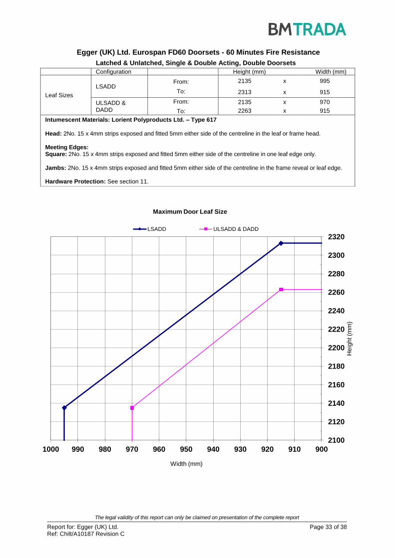
Egger (UK) Ltd. Eurospan FD60 Doorsets - 60 Minutes Fire Resistance
Latched & Unlatched, Single & Double Acting, Double Doorsets
Configuration Height (mm) Width (mm)
Leaf Sizes
LSADD From:
To:
2135 x 995
2313 x 915
ULSADD & DADD
From:
To:
2135 x 970
2263 x 915
Intumescent Materials: Lorient Polyproducts Ltd. – Type 617
Head: 2No. 15 x 4mm strips exposed and fitted 5mm either side of the centreline in the leaf or frame head.
Meeting Edges: Square: 2No. 15 x 4mm strips exposed and fitted 5mm either side of the centreline in one leaf edge only.
Jambs: 2No. 15 x 4mm strips exposed and fitted 5mm either side of the centreline in the frame reveal or leaf edge.
Hardware Protection: See section 11.

The legal validity of this report can only be claimed on presentation of the complete report
Report for: Egger (UK) Ltd. Ref: Chilt/A10187 Revision C
Page 34 of 38
2120
2170
2220
2270
2320
2370
870 890 910 930 950 970 990 1010
He
igh
t (m
m)
Width (mm)
Maximum Door Leaf Size
LSASD ULSASD & DASD
Egger (UK) Ltd. Eurospan FD60 Doorsets - 60 Minutes Fire Resistance - Pyroplex
Latched & Unlatched, Single & Double Acting, Single Doorsets
Configuration Height (mm) Width (mm)
Leaf Sizes
LSASD From:
To:
2130 x 1009
2393 x 895
ULSASD & DASD
From:
To:
2130 x 984
2343 x 895
Intumescent Materials: Pyroplex Ltd. – Pyroplex Rigid Box Seals
Head: 2No. 15 x 4mm strips; one fitted 8mm from the exposed face and the other fitted 8mm from the unexposed
face, in the frame reveal. Jambs: 2No. 15 x 4mm strips; one fitted 8mm from the exposed face and the other fitted 8mm from the unexposed
face, in the frame reveal. Hardware Protection: See section 11.

The legal validity of this report can only be claimed on presentation of the complete report
Report for: Egger (UK) Ltd. Ref: Chilt/A10187 Revision C
Page 35 of 38
2120
2140
2160
2180
2200
900 910 920 930 940
Heig
ht (m
m)
Width (mm)
Maximum Door Leaf Size
LSADD ULSADD & DADD
Egger (UK) Ltd. Eurospan FD60 Doorsets - 60 Minutes Fire Resistance - Pyroplex
Latched & Unlatched, Single & Double Acting, Double Doorsets
Configuration Height (mm) Width (mm)
Leaf Sizes
LSADD From:
To:
2130 x 933
2190 x 908
ULSADD & DADD
From:
To:
2130 x 912
2140 x 908
Intumescent Materials: Pyroplex Ltd. – Pyroplex Rigid Box Seals
Head: 2No. 15 x 4mm strips, one fitted 8mm from the exposed face and the other fitted 8mm from the unexposed
face in the frame head. Meeting Edges: Square: 2No. 15 x 4mm strips, one fitted 8mm from the exposed face and the other fitted 8mm from the unexposed
face in the closing edge of the left hand leaf only. Jambs: 2No. 15 x 4mm strips, one fitted 8mm from the exposed face and the other fitted 8mm from the unexposed
face in the frame reveal. Hardware Protection: See section 11.

The legal validity of this report can only be claimed on presentation of the complete report
Report for: Egger (UK) Ltd. Ref: Chilt/A10187 Revision C
Page 36 of 38
2100
2150
2200
2250
2300
2350
900 910 920 930 940 950 960 970 980 990 1000 1010 1020 1030
He
igh
t (m
m)
Width (mm)
Maximum Door Leaf Size
LSASD ULSASD & DASD
Egger (UK) Ltd. Eurospan FD60 Doorsets - 60 Minutes Fire Resistance – Tall Leaves
Latched & Unlatched, Single & Double Acting, Single Doorsets
Configuration Height (mm) Width (mm)
Leaf Sizes
LSASD From:
To:
2815 x 982
2958 x 926
ULSASD & DASD
From:
To:
2815 x 957
2908 x 926
Maximum Overpanel Height (mm) Transomed 2000
Glazing Max. Glazed Area (m
2) 0.85 (see section 7 for details)
Approved Systems See section 7 & appendix B
Frame Specification
Material Hardwood
Min. Section (mm) 70 x 32
Min. Density (kg/m3) 640
Intumescent Materials: Lorient Polyproducts Ltd. – Type 617
Head: 2No. 15 x 4mm strips exposed and fitted 5mm either side of the centreline in the leaf or frame head.
Jambs: 2No. 15 x 4mm strips exposed and fitted 5mm either side of the centreline in the frame reveal or leaf edge.
Hardware Protection: See section 11.

The legal validity of this report can only be claimed on presentation of the complete report
Report for: Egger (UK) Ltd. Ref: Chilt/A10187 Revision C
Page 37 of 38
2425
2450
2475
2500
2525
1200 1210 1220 1230 1240 1250 1260 1270 1280 1290 1300
He
igh
t (m
m)
Width (mm)
Maximum Door Leaf Size
LSASD ULSASD & DASD
Egger (UK) Ltd. Eurospan FD60 Doorsets - 60 Minutes Fire Resistance – Wide Leaves
Latched & Unlatched, Single & Double Acting, Single Doorsets
Configuration Height (mm) Width (mm)
Leaf Sizes
LSASD From:
To:
2446 x 1265
2506 x 1235
ULSASD & DASD
From:
To:
2446 x 1240
2456 x 1235
Maximum Overpanel Height (mm) Transomed 2000
Glazing Max. Glazed Area (m
2) 0.85 (see section 7 for details)
Approved Systems See section 7 & appendix B
Frame Specification
Material Hardwood
Min. Section (mm) 70 x 32
Min. Density (kg/m3) 640
Intumescent Materials: Lorient Polyproducts Ltd. – Type 617
Head: 2No. 15 x 4mm strips exposed and fitted 5mm either side of the centreline in the leaf or frame head.
Jambs: 2No. 15 x 4mm strips exposed and fitted 5mm either side of the centreline in the frame reveal or leaf edge.
Hardware Protection: See section 11.
The legal validity of this report can only be claimed on presentation of the complete report
Report for: Egger (UK) Ltd. Ref: Chilt/A10187 Revision C
Page 38 of 38
2100
2150
2200
2250
2300
2350
2400
2450
2500
900 950 1000 1050 1100
Heig
ht (m
m)
Width (mm)
Maximum Door Leaf Size
LSADD ULSADD & DADD
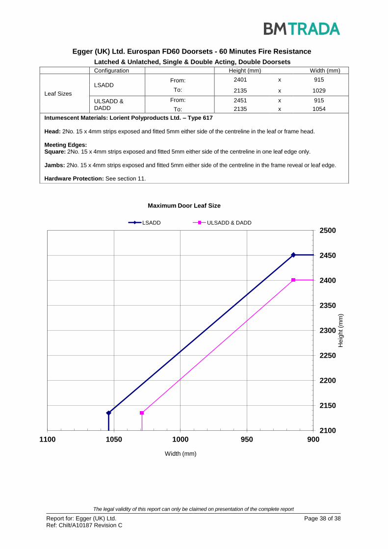
Egger (UK) Ltd. Eurospan FD60 Doorsets - 60 Minutes Fire Resistance
Latched & Unlatched, Single & Double Acting, Double Doorsets
Configuration Height (mm) Width (mm)
Leaf Sizes
LSADD From:
To:
2401 x 915
2135 x 1029
ULSADD & DADD
From:
To:
2451 x 915
2135 x 1054
Intumescent Materials: Lorient Polyproducts Ltd. – Type 617
Head: 2No. 15 x 4mm strips exposed and fitted 5mm either side of the centreline in the leaf or frame head.
Meeting Edges: Square: 2No. 15 x 4mm strips exposed and fitted 5mm either side of the centreline in one leaf edge only.
Jambs: 2No. 15 x 4mm strips exposed and fitted 5mm either side of the centreline in the frame reveal or leaf edge.
Hardware Protection: See section 11.

REGISTERED IN ENGLAND NO. 3125010