fire protection - uthealth...a. pipe, fittings, valves, and connections for sprinkler, standpipe and...
TRANSCRIPT

Fire Protection21 13 13 - Fire Protection Systems (101016)
Mechanical23 00 00 - Basic Mechanical Requiements23 05 13 - Motors23 05 29 - Sleeves Flashings Supports and Anchors23 05 48 - Vibration Isolation23 05 53 - Mechanical Identification23 05 93 - Testing, Adjusting and Balancing (TAB)23 05 93.A - Testing, Adjusting and Balancing - Contractor Responsibilities23 06 20 - Hydronic Specialties23 07 13 - Ductwork Insulation23 07 19 - Piping Insulation23 09 23 - Direct Digital Control Systems23 20 00.A - Piping, Valves and Fittin23 21 00 - Hydronic Piping23 31 00 - Ductwork23 33 00 - Ductwork Accessories23 37 00 - Air Inlets and Outlets23 41 00 - Filters23 73 00 Fan Coil Units
Electrical26 00 00 - Basic Electrical Requirements26 00 00.01 - Electrical Demolition26 05 00 - Basic Electrical Material and Method26 05 19 - Cable Wire and Connectors 600V26 05 29 - Securing and Supporting Methods26 05 33 - Raceway Conduit and Boxes
Fire Alarm28 31 00 - Fire Alarm and Smoke Detection System
E&C Engineers & Consultants Divisions 21, 23, 26 & 28 - 1
E&C No. 3611.00
UTHSC-H SON 520 Freezer Room and Offices Division 21, 23, 26 & 28, Page 1
Houston, TX Index

UTHSC-H SON 520 Freezer Room and Offices Division 21, 23, 26 & 28, Page 2
Houston, TX Index
E&C Engineers & Consultants Divisions 21, 23, 26 & 28 - 2
E&C No. 3611.00
For Construction
E&C Engineers & Consultants, Inc.
TX Firm Registration No: F-003068
Date:
Engineer of Record: Heather Camden, PE
State: of Texas License No: 86883
10-24-2019LIC E N
ESD
86883
HEATHER CAMDEN
THE SEAL APPEARING ON THIS DRAWING WAS AUTHORIZED BY:
E&C Engineers & Consultants Inc.Texas Firm Registration No: F-003068
STATE OF TEXA
S
PROF
ESSIONAL EN
GIN
EER
Digitally signed by Heather CamdenDate: 2019.10.24 15:49:35-05'00'
UTHSC-H SON 520 Freezer Room and Offices Section 21 13 13, Page 1Houston, TX FIRE PROTECTION SYSTEMS
E&C Engineers & Consultants Inc. 21 13 13 - 1 E&C Job No. 3611.00
SECTION 21 13 13
FIRE PROTECTION SYSTEMS
PART 1 GENERAL
1.01 The following sections are to be included as if written herein:
A. Section 23 00 00 – Basic Mechanical RequirementsB. Section 23 05 29 – Sleeves, Flashings, Supports and Anchors
1.02 SECTION INCLUDES
A. Pipe, fittings, valves, and connections for sprinkler, standpipe and fire hose, and combination sprinkler and standpipe systems.
1.03 SCOPE OF WORK
A. The scope of this project is to add and relocate fire protection as required to properly cover the space as noted with the revised architectural background. This specification is based on the OFPC mater, which is assumed to have been used during original sprinkler design. The intent is to match existing heads and pipe. Verify head type prior to ordering new materials.
1.04 RELATED SECTIONS
B. Section 23 20 00.A - Piping, Valves and Fittings
1.05 REFERENCES
A. ANSI/ASME B16.1 - Cast Iron Pipe Flanges and Flanged Fittings, Class 25, 125, 250, and 800.
B. ANSI/ASME B16.3 - Malleable Iron Threaded Fittings, Class 150 and 300.C. ANSI/ASME B16.4 - Cast Iron Threaded Fittings, Class 125 and 250.D. ANSI/ASME B16.5 - Pipe Flanges and Flanged Fittings.E. ANSI/ASME B16.9 - Factory-made Wrought Steel Buttwelding Fittings.F. ANSI/ASME B16.11 - Forged Steel Fittings, Socket-welding and Threaded.G. ANSI/ASME B16.18 - Cast Copper Alloy Solder-Joint Pressure Fittings.H. ANSI/ASME B16.22 - Wrought Copper and Copper Alloy Solder Joint Pressure Fittings.I. ANSI/ASME B16.25 - Buttwelding Ends.J. ANSI/ASME B36.10 - Welded and Seamless Wrought Steel Pipe.K. ANSI/ASME Sec 9 - Welding and Brazing Qualifications.L. ANSI/ASTM A135 - Electric-Resistance-Welded Steel Pipe.M. ANSI/ASTM A47 - Malleable Iron Castings.N. ANSI/ASTM B32 - Solder Metal.O. ANSI/AWS A5.8 - Brazing Filler Metal.P. ANSI/AWWA C110 - Ductile Iron and Gray Iron Fittings.Q. ANSI/AWWA C151 - Ductile Iron Pipe, Centrifugally Cast.R. ASTM A53 - Pipe, Steel, Black and Hot-Dipped, Zinc-coated Welded and Seamless.S. ASTM A120 - Pipe, Steel, Black and Hot-Dipped, Zinc-coated (Galvanized) Welded and
Seamless, for Ordinary Uses.T. ASTM A234 - Piping Fittings of Wrought Carbon Steel and Alloy Steel for Moderate and
Elevated Temperatures.U. ASTM A795 - Black and Hot-Dipped Zinc-Coated (Galvanized) Welded and Seamless
Steel Pipe for Fire Protection Use.

UTHSC-H SON 520 Freezer Room and Offices Section 21 13 13, Page 2Houston, TX FIRE PROTECTION SYSTEMS
E&C Engineers & Consultants Inc. 21 13 13 - 2 E&C Job No. 3611.00
V. ASTM B75 - Seamless Copper Tube.W. ASTM B88 - Seamless Copper Water Tube.X. ASTM B251 - General Requirements for Wrought Seamless Copper and Copper-Alloy
Tube.Y. ASTM F442 - Chlorinated Poly (Vinyl Chloride) (CPVC) Plastic Pipe (SDR-PR).Z. AWS D10.9 - Specifications for Qualification of Welding Procedures and Welders for
Piping and Tubing.AA. NFPA 13 - Installation of Sprinkler Systems.BB. NFPA 14 - Standpipe and Hose Systems.CC. NFPA 24 - Installation of Private Fire Service Mains and Their AppurtenancesDD. UL - Fire Protection Equipment Directory.EE. City of Houston, Texas, Fire Department Standards.FF. State of Texas, State Fire Marshal Rules.GG. All hose threads, coupling types, etc., utilized in the fire protection systems shall conform
to the standards and requirements of the City of Houston, Texas Fire Department.
1.06 SUBMITTALS
A. Submit under provisions of Section 23 00 00.B. Shop Drawings: Indicate pipe materials used, jointing methods, supports, floor and wall
penetration seals. Indicate installation, layout, weights, mounting and support details, and piping connections.
C. Product Data: Provide data on sprinkler heads, valves, and specialties, including manufacturer’s catalogue information. Submit performance ratings rough-in details, weights, support requirements, and piping connections.
D. Manufacturer's Certificate: Certify that system has been tested and meets or exceeds requirements specified, and suggested by listed codes.
E. Provide certificate of compliance from authority have jurisdiction indicating approval of field acceptance tests.
1.07 OPERATION AND MAINTENANCE DATA
A. Submit under provisions of Section 23 00 00.B. Maintenance Instructions: Include installation instructions, spare parts lists, procedures,
and treatment programs.
1.08 QUALITY ASSURANCE
A. Sprinkler Systems: Perform work to NFPA 13.B. Standpipe and Hose Systems: Perform to NFPA 14.C. Welding Materials and Procedures: Perform to ASME Code.D. Equipment and Components: Bear FM label or marking. Provide manufacturer's name
and pressure rating marked on valve body.E. Maintain one copy of each document on site.F. Design system under direct supervision of a Professional Engineer experienced in design
of this work and licensed in the State of Texas. All design submittal documents and shop drawings shall bear the responsible engineers signed and dated seal.
G. All parts of fire protection piping systems shall conform to all provisions of Underwriters' Laboratories requirements. All equipment shall bear the Underwriters' Laboratories label of approval.
1.09 DELIVERY, STORAGE, AND HANDLING
A. Deliver, store, protect, and handle products to site under provisions of Section 23 00 00.B. Deliver and store valves in shipping containers, with labeling in place.
UTHSC-H SON 520 Freezer Room and Offices Section 21 13 13, Page 3Houston, TX FIRE PROTECTION SYSTEMS
E&C Engineers & Consultants Inc. 21 13 13 - 3 E&C Job No. 3611.00
C. Provide temporary protective coating on cast iron and steel valves.D. Provide temporary end caps and closures on piping and fittings. Maintain in place until
installation.
PART 2 PRODUCTS
2.01 WALL, FLOOR AND CEILING PLATES:
A. See Section 23 05 29.
2.02 SLEEVES, INSERTS, AND FASTENINGS:
A. General: All openings through all floors, walls, and roofs, etc., regardless of material for the passage of piping, etc., shall be sleeved.
B. See Section 23 05 29.
2.03 UNIONS:
A. See Section 23 20 00.A.
2.04 FLANGES:
A. See Section 23 20 00.A.
2.05 BACKFLOW PREVENTERS: Backflow preventers (BFP) shall be reduced pressure type, Febco 825, Watts or approved equal. A BFP shall be installed to isolate all non-potable water requirements from the building domestic water system. (All BFP's shall be installed within the building.)
2.06 MATERIALS:
A. PIPING:1. All pipe used for fire protection standpipe systems and fire sprinkler systems
shall be Schedule 40 black steel pipe. See Section 23 20 00.A. All piping 2 1/2" and larger shall be welded, unless otherwise indicated herein.
2. Use of piping, when approved by UT System, shall be “roll” grooved type; cut grooved pipe is not permitted.
3. No pipe smaller than 4" nominal pipe size shall be used for standpipe systems except for individual runout to one hose cabinet. The 1-1/2" or 2-1/2" runout to cabinet shall have a maximum center line height of 60".
4. Scheduled 10 pipe is not permitted.B. FITTINGS:
1. All welding type steel fittings employed in fabricating fire protection standpipe system and fire sprinkler systems shall conform to A.S.T.M. Specification A-234 and ANSI Standard B16.9-1964. All threaded fittings shall be 300 pound malleable iron fittings. Grooved type fittings will not be accepted for use in standpipe systems unless specifically indicated. Pipe size changes shall be performed through the use of reducing tees or reducers designed for that purpose. The use of bushings is explicitly prohibited.
UTHSC-H SON 520 Freezer Room and Offices Section 21 13 13, Page 4Houston, TX FIRE PROTECTION SYSTEMS
E&C Engineers & Consultants Inc. 21 13 13 - 4 E&C Job No. 3611.00
2. Unless otherwise shown or required, all fittings shall be welding type steel fittings. See Section 23 20 00.A.
3. Threaded fittings shall be used when shown and shall be used from the point of connection of the pipe to the riser to each fire hose cabinet. Threaded fittings shall be Crane or Grinnell Company's 300 pound malleable iron fittings.
4. Grooved end couplings 2 ½” and larger shall be Victaulic Style 07 “Zero-Flex” Rigid Coupling, with EPDM gasket (minimum 700 psi working pressure) for use with roll grooved piping. Products by Gustin-Bacon, Gruvlok are acceptable or Engineer-approved equal. Reducing type couplings, outlet couplings, “T” outlet fittings, cut-in style fittings, snap joint couplings, and flange adapter type fittings are not acceptable. Provide grooved fittings similar to standard weld fittings.
5. Extra heavy "Thread-o-lets" shall be used at each point of departure from the riser to the fire hose or valve cabinet. A "Thread-o-let" shall be installed below the level of the valve in the cabinet and a minimum of two (2) threaded ells shall be used to provide a swing joint connection from the riser to the valve in the cabinet.
6. Refer to Section 23 20 00.A for additional requirements.
2.07 VALVES:
A. See Section 23 20 00.A.
2.08 SPRINKLER SYSTEM
A. SYSTEM DESCRIPTION1. System to provide coverage for entire building and the entire area of the
renovation.2. Provide system to NFPA 13 light hazard occupancy requirements unless
otherwise noted.3. Interface system with building fire and smoke alarm system.
B. SUBMITTALS1. Submit under provisions of Section 23 00 00.2. Preliminary Shop Drawings: Prior to detailed submission, submit preliminary
layout of finished ceiling areas indicating only head locations coordinated with ceiling installation.
3. Shop Drawings: Indicate hydraulic calculations, detailed pipe layout, hangers and supports, components and accessories. Indicate system controls.
4. Submit shop drawings, product data, and hydraulic calculations for review. Submit copies of all information, and review comments to Architect/Engineer and Owner.
5. Samples: Submit two of each style of sprinkler head specified.C. PROJECT RECORD DOCUMENTS
1. Submit under provisions of Section 23 00 00.2. Record actual locations of sprinkler heads and deviations of piping from
drawings. Indicate drain and test locations.D. OPERATION AND MAINTENANCE DATA
1. Submit under provisions of Section 23 00 00.2. Maintenance Data: Include components of system, servicing requirements,
Record Drawings, inspection data, replacement part numbers and availability, and location and numbers of service depot.
E. QUALITY ASSURANCE1. Perform Work in accordance with NFPA 13.2. Equipment and Components: Bear FM label or marking.3. Maintain one copy of all documents on site.
F. EXTRA MATERIALS

UTHSC-H SON 520 Freezer Room and Offices Section 21 13 13, Page 5Houston, TX FIRE PROTECTION SYSTEMS
E&C Engineers & Consultants Inc. 21 13 13 - 5 E&C Job No. 3611.00
1. Furnish under provisions of Section 23 00 00.2. Provide extra sprinkler heads as suggested under provisions of NFPA 13.3. Provide suitable wrenches for each head type.4. Provide metal storage cabinet in location designated.
G. PRODUCTS1. General: The Contractor shall provide all components required for the complete
installation of automatic sprinkler systems as hereinafter specified and indicated on the Drawings.
2. Qualifications of the Installer: The system shall be installed by a firm regularly engaged in the design and installation of automatic sprinkler systems in accordance with requirements of the National Fire Protection Association and Fire Protection and Engineering Bureau of Texas, or by an authorized agent of such firm. Evidence to support the above requirements may be required and any proposed installer who cannot show suitable experience will be rejected.
3. System Layout: The fire sprinkler areas, piping, head locations, etc. as indicated is only for Contractor's reference as to areas to be protected and possible piping routes. If header or manifold sizes are given in the drawings, then the sizes given shall be the minimum sizes installed. Actual number, spacing and location of heads, size and routes of piping shall be provided in accordance with the applicable Specifications and acceptable Shop Drawings. All layouts, head spacing, coverage, etc., as may be required by the referenced authorities and/or Architectural and Structural conditions shall be made without increase in cost to the Owner or the Architect/Engineer. Modifications to head spacing, pipe routes, etc. shall be closely coordinated with the work of all other trades. The Fire Sprinkler Subcontractor shall be responsible for the design and installation of the fire sprinkler system as described herein and on the project drawings. The piping of the system shall be sized used the "hydraulic" method, as included in NFPA Standard No. 13. Piping sized using the "schedule" method is unacceptable, except where expanding an existing "scheduled" system.
4. Shop Drawings: Shop Drawings shall be submitted prior to fabrication. The Shop Drawings shall include detail plans of sprinkler systems including piping sizes, sections and plot plan indicating the locations of underground supply connections, control valves, fire department connections, and other equipment to be used. The Shop Drawings shall become an integral part of these Specifications.
5. Materials and Equipment:a. General: All materials and equipment used in the installation of the
sprinkler system shall be listed as approved by the Underwriters' Laboratories, Inc., List of Inspected Fire Protection Equipment and Materials, or the Factory Mutual Testing Laboratories List of Approved Equipment, Fire Protection Devices and Devices Involving Fire Hazard, and shall be the latest design of the manufacturer. All piping, control valves, drain valves, fittings, etc. shall be as specified under this Section, Fire Protection System, & in Section 23 20 00.A utilizing welded, flanged, and threaded fittings only. Where valves are not specified by Figure No. they shall be of specified manufacture, U.L. listed for service, and of same quality level as Figure Nos. specified. All pipe 2 1/2" and larger shall be welded, except as may be allowed herein. All pipe 2" and smaller shall be threaded using 300 pound malleable iron, A135 Schedule 40 black steel pipe and fittings. Note that if galvanized pipe or fittings are installed in other than dry systems, the contractor shall be responsible to remove the galvanized pipe or fittings and replace them with specified materials as soon as possible prior to further installation of the system. (EXCEPTION: Dry pipe systems shall be hot dipped galvanized pipe and fittings of same schedule as dry systems, per Factory Mutual recommendations.)

UTHSC-H SON 520 Freezer Room and Offices Section 21 13 13, Page 6Houston, TX FIRE PROTECTION SYSTEMS
E&C Engineers & Consultants Inc. 21 13 13 - 6 E&C Job No. 3611.00
6. Sprinkler Heads:a. Unless otherwise specified or indicated on the Drawings, sprinkler heads
shall be quick response type spray heads of the upright or pendant ordinary degree temperature rating type except that sprinkler heads to be installed in the vicinity of heating equipment and lights shall be of the temperature rating required for such locations by National Fire Protection Association Standard No. 13. Chrome plated bronze heads shall be installed in all locations. Ceiling sprinklers shall be Concealed Sprinkler Heads- Quick Response. Concealed sprinkler heads shall be solder link operated Viking Horizon Mirage-HP Model B 2 Quick Response concealed automatic sprinkler rated at 160°F and 175 psi. Cover plate shall be rated at 135°F and it shall be selected by the architect form the manufacturer’s standard color selections to match the color of ceiling in each area. Uprights shall be Grinnel No. F950 brass upright.
b. Heads shall be located in a symmetrical pattern related to ceiling features such as grid, beams, light fixtures, diffusers, etc., and where applicable, heads shall be located symmetrically with the ceiling grid, centered in two directions.
c. The Contractor shall provide spare heads equal to one percent (1%) of the total number of heads installed under the Contract, but not less than ten (10). The heads shall be packed in a suitable wall mounted sprinkler cabinet and shall be representative of, and in proportion to, the number of each type and temperature rating heads installed. In addition to the spare heads, the Contractor shall provide not less than one special sprinkler head wrench for each type of head. The cabinet shall be located where directed by the Construction Inspector.
7. Piping: Installation of piping, fittings and valves shall be as specified in Chapter 3, System Components, NFPA Standard No. 13, except where noted otherwise. Piping shall be concealed in all areas with finished ceilings. Piping shall be sterilized as specified in Section 23 20 00.A. The O.S. & Y. valves shall be provided under Section 23 20 00.A.Note that the use of piping bushings for any purpose is explicitly prohibited.
8. Water Flow Alarm Switch: Provide, where indicated on the Drawings, McDonnell UL approved line size flow switches. Flow switch shall be provided with delay, adjustable up to 90 seconds (60 to 90 seconds in Austin). See Division 26 for electrical signal connection by others to these flow switches.
H. Hydrostatically test entire system per NFPA 13 procedure and at least 150 percent of charge or working pressure, whichever is greater.
I. Require test be witnessed by campus Fire Marshal.J. Add locations and hazards as required by project conditions.
Location System Type/HazardOffices Light Hazard
2.09 STANDPIPE SYSTEMS:
A. General: The Contractor shall provide all components required for the complete installation of standpipe systems as hereinafter specified and indicated on the Drawings.

UTHSC-H SON 520 Freezer Room and Offices Section 21 13 13, Page 7Houston, TX FIRE PROTECTION SYSTEMS
E&C Engineers & Consultants Inc. 21 13 13 - 7 E&C Job No. 3611.00
B. Qualifications of the Installer: The system shall be installed by a firm regularly engaged in the design and installation of automatic sprinkler systems in accordance with requirements of the National Fire Protection Association and Fire Protection and Engineering Bureau of Texas, or by an authorized agent of such firm. Evidence to support the above requirements may be required and any proposed installer who cannot show suitable experience will be rejected.
C. System Layout: The fire zones, piping, etc. as indicated is only for Contractor's reference as to areas to be protected and for possible piping routes. If header or manifold sizes are given in the drawings, then the sizes given shall be the minimum sizes installed. Actual number, spacing and locations, size and routes of piping shall be provided in accordance with the applicable Specifications and acceptable Shop Drawings. All layouts, coverage, etc., as may be required by the referenced authorities and/or Architectural and Structural conditions shall be made without increase in cost to the Owner or the Architect/Engineer. Modifications to head spacing, pipe routes, etc. shall be closely coordinated with the work of all other trades. The Fire Sprinkler Subcontractor shall be responsible for the design and installation of the fire system as described herein and on the project drawings.
D. Shop Drawings: Shop Drawings shall be submitted prior to fabrication. The Shop Drawings shall include detail plans of systems including piping sizes, sections and plot plan indicating the locations of underground supply connections, control valves, fire department connections, and other equipment to be used. The Shop Drawings shall become an integral part of these Specifications. Submit to Factory Mutual for review and comment.
E. Materials and Equipment: 1. General: All materials and equipment used in the installation of the sprinkler
system shall be listed as approved by the Underwriters' Laboratories, Inc., List of Inspected Fire Protection Equipment and Materials, or the Factory Mutual Testing Laboratories List of Approved Equipment, Fire Protection Devices and Devices Involving Fire Hazard, and shall be the latest design of the manufacturer. All piping, control valves, drain valves, fittings, etc. shall be as specified under this Section, utilizing welded, flanged, and threaded fittings only. Where valves are not specified by Figure No. they shall be of specified manufacture, U.L. listed for service, and of same quality level as Figure Nos. specified. All pipe 2 1/2" and larger shall be welded, except as may be allowed herein. All pipe 2" and smaller shall be threaded using 300 pound malleable iron, A120 Schedule 40 black steel pipe and fittings. Note that if galvanized pipe or fittings are installed, the contractor shall be responsible to remove the galvanized pipe or fittings and replace them with specified materials as soon as possible prior to further installation of the system.
2.10 FIRE VALVE CABINET:
A. Fire valve cabinet shall be Allenco recessed cabinet Model No. 280. Door shall be hollow welded construction with semi-concealed hinge and semi-recessed cam action latch. Door style to be "S" steel. Cabinet shall be 16 gauge body and trim style "L", baked white enamel inside, white prime coat outside.
B. Fire angle valve, Allenco #170U 2-1/2 x 2-1/2, 150 pound angle valve, cast brass body, satin trim, complete with red enamel malleable iron handle. Male outlet shall have 7-1/2 threads per inch hosepipe thread, Allenco #120 cast brass pin lug cap and chain.

UTHSC-H SON 520 Freezer Room and Offices Section 21 13 13, Page 8Houston, TX FIRE PROTECTION SYSTEMS
E&C Engineers & Consultants Inc. 21 13 13 - 8 E&C Job No. 3611.00
2.11 FIRE EXTINGUISHER CABINETS:
A. Fire extinguisher cabinets shall be Allenco No. 285A Custom Recessed, No. 285 AT Custom Shallowall for semi-recessed or No. 285 AW Custom Surface as required. Cabinets shall have hollow welded door and clean welded corners for recessed types and clean welded 2-inch radius bend on trim for semi-recessed and surface mounted units. Cabinets shall have semi-concealed continuous hinge, keyed alike cylinder locks and break glass in door. Cabinets shall be furniture grade steel with baked white enamel finish inside and white prime coat outside.
B. All cabinets shall have minimum inside dimension of 12" wide, 27” high and 7-1/2" deep. Furnish in each cabinet an AMEREX or equal No. 441, 10 lb. multipurpose Red Fire Extinguisher, dry chemical for A, B or C use, U.L. rated 4A-30B-C, FM approved, dry air or nitrogen pressurized.
2.12 ROOF MANIFOLDS:
A. Roof manifolds shall be equal to W.D. Allen Company's No. 439 cast brass Underwriters' Laboratory listed horizontal roof manifold. Complete with Allenco No. 17OU 2-1/2" Underwriters' listed angle valve and Allenco No. 120 2-1/2" brass caps and chains, 2-way, 2-1/2" x 2-1/2" x 4". 2-1/2" outlets shall be 7-1/2 threads per inch iron pipe size.
B. Systems shall be flushed through a temporary hose until the system is clean. Any leaks found shall be remedied in each instance in a manner approved in advance by the Owner's duly authorized representative. The systems shall be alternately tested and repaired where necessary until they have demonstrated their capability to withstand the test pressure for a period of 24 hours without any appreciable drop in the test pressure initially applied.
PART 3 EXECUTION
3.01 PREPARATION - All systems:
A. Ream pipe and tube ends. Remove burrs. Bevel plain end ferrous pipe.B. Remove scale and foreign material, from inside and outside, before assembly.C. Prepare piping connections to equipment with flanges or unions.D. Flush entire system of foreign matter.
3.02 SYSTEM TESTS
A. Hydrostatically test entire standpipe system in accordance with NFPA 14 and sprinkler in accordance with NFPA 13.
B. Test shall be witnessed by campus Fire Marshal.
3.03 INSTALLATION
A. SPRINKLERS1. Install piping in accordance with NFPA 13 for sprinkler systems, NFPA 14 for
standpipe and hose systems, and NFPA 24 for service mains. Note that the piping sizes indicated in the plans are the minimum acceptable. The Qualified Contractor shall provide proper sizes, materials and installation as required in the appropriate NFPA Standard.
2. Route piping in orderly manner, plumb and parallel to building structure. Maintain gradient.
3. See Section 23 20 00.A and 23 05 29.
UTHSC-H SON 520 Freezer Room and Offices Section 21 13 13, Page 9Houston, TX FIRE PROTECTION SYSTEMS
E&C Engineers & Consultants Inc. 21 13 13 - 9 E&C Job No. 3611.00
4. Slope piping and arrange systems to drain at low points. Use eccentric reducers to maintain top of pipe level.
5. Provide drain valves at main shut-off valves, low points of piping and apparatus. Provide Fire Department test station, piped to drain.
6. Locate outside alarm gong on building wall as indicated.7. Place pipe runs to minimize obstructions with other work.8. Place piping in concealed spaces above finished ceilings.9. Center heads in two directions in ceiling tile and provide piping offsets as
required.10. Apply paper cover to ensure concealed sprinkler head and cover plates do not
receive field paint finish.11. Install and connect fire pumps in accordance with Section 21 30 00 and NFPA
13.12. Locate fire department connection with sufficient clearance from walls,
obstructions, or adjacent Siamese connectors to allow full swing of fire department wrench handle.
B. STANDPIPES1. Fire standpipe risers shall be located at the stairs as shown on the drawings.
System shall be empty (dry without air pressurization) and shall be complete with fire valves for Fire Department hose connections.
2. Install in accordance with manufacturer's instructions.3. Install in accordance with NFPA 14 for standpipe and hose systems.4. Locate and secure hose cabinet plumb and level. Establish top of cabinet
surface 66 inches above finished floor.5. All polyester hoses must be new and unused at the time of acceptance of the
project.6. Locate angle valve in cabinet at 60 inches above floor.7. Locate dry chemical fire extinguisher in cabinet.8. Connect standpipe system to water source ahead of domestic water connection.9. Where static pressure exceeds 100 psi at any hose station, provide pressure
reducing valve to prevent pressure on hose exceeding 90 psi.10. Provide two-way fire department outlet connection on roof.
3.04 GENERAL FABRICATION OF PIPE:
A. See Section 23 20 00.A.
END OF SECTION


UTHSC-H SON 520 Freezer Room and Offices Section 23 00 00, Page 1Houston, TX BASIC MECHANICAL REQUIREMENTS
E&C Engineers & Consultants Inc. 23 00 00 - 1 E&C Job No. 3611.00
SECTION 23 00 00BASIC MECHANICAL REQUIREMENTS
PART 1 GENERAL
1.01 SECTION INCLUDES
A. Basic Mechanical Requirements specifically applicable to Division 23 Sections, in addition to Division 01 - General Requirements.
1.02 RELATED DOCUMENTS:
A. THE UNIFORM GENERAL CONDITIONS, SUPPLEMENTARY GENERAL CONDITIONS, and DIVISION 01 of the Specifications apply to the work specified in this Section.
B. All work covered by this Section of these Specifications shall be accomplished in accordance with all applicable provisions of the Contract Documents and any addenda or directives which may be issued herewith, or otherwise.
1.03 GENERAL:
A. The Contractor shall execute all work hereinafter specified or indicated on accompanying Drawings. Contractor shall provide all equipment necessary and usually furnished in connection with such work and systems whether or not mentioned specifically herein or on the Drawings.
B. The Contractor shall be responsible for fitting his material and apparatus into the building and shall carefully lay out his work at the site to conform to the structural conditions, to avoid all obstructions, to conform to the details of the installation and thereby to provide an integrated satisfactory operating installation.
C. The Mechanical, Electrical, and associated Drawings are necessarily diagrammatic by their nature, and are not intended to show every connection in detail or every pipe or conduit in its exact location. These details are subject to the requirements of standards referenced elsewhere in these specifications, and structural and architectural conditions. The Contractor shall carefully investigate structural and finish conditions and shall coordinate the separate trades in order to avoid interference between the various phases of work. Work shall be organized and laid out so that it will be concealed in furred chases and suspended ceilings, etc., in finished portions of the building, unless specifically noted to be exposed. All exposed work shall be installed parallel or perpendicular to the lines of the building unless otherwise noted.
D. When the mechanical and electrical Drawings do not give exact details as to the elevation of pipe, conduit and ducts, the Contractor shall physically arrange the systems to fit in the space available at the elevations intended with proper grades for the functioning of the system involved. Piping, exposed conduit and the duct systems are generally intended to be installed true and square to the building construction, and located as high as possible against the structure in a neat and workmanlike manner. The Drawings do not show all required offsets, control lines, pilot lines and other location details. Work shall be concealed in all finished areas.
1.04 DEFINITIONS: (Note: These definitions are included here to clarify the direction and intention of this specification. The list given here is not by any means complete. For further clarification as required, contractor shall contact the designated owner’s representative.)

UTHSC-H SON 520 Freezer Room and Offices Section 23 00 00, Page 2Houston, TX BASIC MECHANICAL REQUIREMENTS
E&C Engineers & Consultants Inc. 23 00 00 - 2 E&C Job No. 3611.00
A. CONCEALED / EXPOSED: Concealed areas are those areas which cannot be seen by the building occupants. Exposed areas are all areas which are exposed to view by the building occupants, including under counters, inside cabinets and closets, plus all mechanical rooms.
B. General Requirements: The provisions of requirements of other Division 01 sections apply to entire work of contract and, where so indicated, to other elements which are included in project. Basic contract definitions are included in the General Conditions.
C. Indicated: The term "indicated" is a cross reference to graphic representations, notes or schedules on drawings, to other paragraphs or schedules in the Specifications, and to similar means of recording requirements on contract documents. Where terms such as "shown", "noted", "scheduled", and "specified" are used in lieu of "indicated", it is for the purpose of helping reader locate the cross reference, and no limitation of location is intended except as specifically noted.
D. Directed, requested, etc.: Where not otherwise explained, terms such as "directed", "requested", "authorized", "selected", "approved", "required", "accepted", and "permitted" mean directed by Architect/Engineer", "requested by Architect/Engineer" and similar phrases. However, no such implied meaning will be interpreted to extend Architect's/Engineer's responsibility into Contractor's area of construction supervision and job safety.
E. And/Or: Where "and/or" is used in these Specifications or on the Drawings, it shall mean "that situations exist where either one or both conditions occur or are required and shall not be interpreted to permit an option on the part of the Contractor.
F. Approve: Where used in conjunction with Architect's/Engineer's response to submittals, requests, applications, inquiries, reports and claims by Contractor, the meaning of term "approved" will be held to limitations to Architect's/Engineer's responsibilities and duties as specified in General and Supplementary Conditions. In no case will "approval" by Architect/Engineer be interpreted as a release of Contractor from responsibilities to fulfill requirements of contract documents or to extend Architect's/Engineer's responsibility into Contractor's area of construction supervision and job safety.
G. As required: Where "as required" is used in these Specifications or on the drawings, it shall mean "that situations exist that are not necessarily described in detail or indicated that may cause the contractor certain complications in performing the work described or indicated. These complications entail the normal coordination activities expected of the Contractor where multiple trades are involved and new or existing construction causes deviations to otherwise simplistic approaches to the work to be performed. The term shall not be interpreted to permit an option on the part of the Contractor to achieve the end result."
H. Furnish:
1. The term "furnish" is used to mean "supply and deliver to project site, ready for unloading, unpacking, assemble, installation, and similar operations."
2. Where "furnish" applies to work for which the installation is not otherwise specified, "furnish" in such case shall mean "furnish and install."
I. Install: The term "install" is used to describe operations at project site including "unloading, unpacking, assembly, erection, placing, anchoring, applying, working to dimension, finishing, curing, protecting, cleaning and similar operation."

UTHSC-H SON 520 Freezer Room and Offices Section 23 00 00, Page 3Houston, TX BASIC MECHANICAL REQUIREMENTS
E&C Engineers & Consultants Inc. 23 00 00 - 3 E&C Job No. 3611.00
J. Provide: The term "provide" means "to furnish and install, complete and ready for intended use."
1.05 PERMITS, UTILITY CONNECTIONS AND INSPECTIONS:
A. General: Refer to DIVISION 01 for construction phasing and time increments.
B. Fees and Costs: Refer to Division 01 for payment requirements of fees and utility costs.
C. All work performed on this project is under the authority of the State of Texas, therefore no local construction fees or construction permits will be required except as may be required for new service taps, or new or modified connections to City controlled services. If inspections by City personnel are specifically required by this document, refer to Division 01 for responsibility.
D. Compliance: The Contractor shall comply in every respect with all requirements of National Fire Protection Association, local Fire Department regulations and utility company requirements. In no case does this relieve the Contractor of the responsibility of complying with these Specifications and Drawings where specified conditions are of higher quality than the requirements of the above-specified authorities. Where requirements of the Specifications and Drawings are more lenient than the requirements of the above authorities having jurisdiction, the Contractor shall make installations in compliance with the requirements of the above authorities with no extra compensation.
1.06 CONTRACT DOCUMENTS:
A. All dimensional information related to new structures shall be taken from the appropriate Drawings. All dimensional information related to existing facilities shall be taken from actual measurements made by the Contractor on the site.
B. The interrelation of the Specifications, the Drawings, and the schedules are as follows: The Specifications determine the nature and setting of the several materials, the Drawings establish the quantities, dimensions and details, and the schedules give the performance characteristics. If the Contractor requires additional clarification, he shall request it in writing, following the contractually prescribed information flow requirements.
C. Should the Drawings or Specifications conflict within themselves, or with each other, the better quality, or greater size or quantity of work or materials shall be performed or furnished.
1.07 FUTURE WORK
A. Provide for future work under requirements of Section 01 11 00.
1.08 SUBMITTALS
A. Refer to Uniform General Conditions.
B. Proposed Products List: Include Products specified in the following Sections:
1. Section 23 00 04 – Ductwork Cleaning
2. Section 23 05 29 - Sleeves, Flashings, Supports and Anchors

UTHSC-H SON 520 Freezer Room and Offices Section 23 00 00, Page 4Houston, TX BASIC MECHANICAL REQUIREMENTS
E&C Engineers & Consultants Inc. 23 00 00 - 4 E&C Job No. 3611.00
3. Section 23 05 93 – Testing, Adjusting and Balancing (TAB)
4. Section 23 05 93A – Testing, Adjusting and Balancing Contractor Responsibilities
5. Section 23 07 13 - Ductwork Insulation
6. Section 23 31 00 - Ductwork
7. Section 23 33 00 - Ductwork Accessories
8. Section 23 37 00 - Air Inlets and Outlets
C. Submit shop drawings and product data grouped to include complete submittals of related systems, products, and accessories in a single submittal.
D. Mark dimensions and values in units to match those specified.
E. Submit Fabrication Drawings whenever (1) equipment proposed varies in physical size and arrangement from that indicated on the Drawings, thus causing rearrangement of equipment space, (2) where tight spaces require extreme coordination between ductwork, piping, conduit, and other equipment, (3) where called for elsewhere in these Specifications; and (4) where specifically requested by the Architect/Engineer. Fabrication Drawings shall be made at no additional charge to the Owner or the Architect/Engineer.
F. All required Fabrication Drawings, except as noted otherwise, shall be prepared at a scale of not less than 1/4" = 1'-0". Fabrication Drawings for ductwork, air handling units, and sections in Mechanical Rooms shall be drawn at a minimum scale of 3/8" = 1'-0". Submit three blueline prints of each Fabrication Drawing to the Architect/Engineer for review. Reproduction and submittal of the Construction Documents is not acceptable. The Architect/Engineer will review the drawing and return one print with comments.
1.09 SUBSTITUTION OF MATERIALS AND EQUIPMENT:
A. Refer to General Conditions for substitution of materials and equipment.
B. General: Within thirty days after the date of contract award or work order, whichever is later, and before purchasing or starting installation of materials or equipment, the Contractor shall submit for review, a complete list of suppliers, contractors and manufacturers for all materials and equipment which will be submitted for incorporation into the project. The list shall be arranged in accordance with the organization of the Specifications. This initial list shall include the manufacturer's name and type or catalog number as required to identify the quality of material or equipment proposed. This list will be reviewed by the Engineer and the Owner and will be returned to the Contractor with comments as to which items are acceptable without further submittal data and which items will require detailed submittal data for further review and subsequent approval. The initial list shall be submitted as herein specified. Materials and equipment requiring detailed submittal data shall be submitted with sufficient data to indicate that all requirements of these Specifications have been met and samples shall be furnished when requested. All manufacturer's data used as part of the submittal shall have all inapplicable features crossed out or deleted in a manner that will clearly indicate exactly what is to be furnished.
C. It is not the intent of the Drawings and/or Specifications to limit products to any particular manufacturer nor to discriminate against an "APPROVED EQUAL" product as produced by

UTHSC-H SON 520 Freezer Room and Offices Section 23 00 00, Page 5Houston, TX BASIC MECHANICAL REQUIREMENTS
E&C Engineers & Consultants Inc. 23 00 00 - 5 E&C Job No. 3611.00
another manufacturer. Some proprietary products are mentioned to set a definite standard for acceptance and to serve as a reference in comparison with other products. When a manufacturer's name appears in these Specifications, it is not to be construed that the manufacturer is unconditionally acceptable as a provider of equipment for this project. The successful manufacturer or supplier shall meet all of the provisions of the appropriate specification(s).
D. The specified products have been used in preparing the Drawings and Specifications and thus establish minimum qualities with which substitutes must at least equal to be considered acceptable. The burden of proof of equality rests with the Contractor. The decision of the designer is final.
E. When requested by the Architect/Engineer, the Contractor shall provide a sample of the proposed substitute item. In some cases, samples of both the specified item and the proposed item shall be provided for comparison purposes.
F. Timeliness: The burden of timeliness in the complete cycle of submittal data, shop Drawings, and sample processing is on the Contractor. The Contractor shall allow a minimum of six (6) weeks time frame for review of each submission by the office of the design discipline involved after receipt of such submissions by that design discipline. The Contractor is responsible for allowing sufficient time in the construction schedule to cover the aforementioned cycles of data processing, including time for all resubmittal cycles on unacceptable materials, equipment, etc. covered by the data submitted. Construction delays and/or lack of timeliness in the above regard are the responsibility of the Contractor and will not be considered in any request for scheduled construction time extensions and/or additional costs to the Owner.
G. All equipment installed on this project shall have local representation, local factory authorized service, and a local stock of repair parts.
H. Acceptance of materials and equipment will be based on manufacturer's published data and will be tentative subject to the submission of complete shop Drawings indicating compliance with the contract documents and that adequate and acceptable clearances for entry, servicing, and maintenance will exist. Acceptance of materials and equipment under this provision shall not be construed as authorizing any deviations from the Specifications, unless the attention of the Architect/Engineer has been directed in writing to the specific deviations. Data submitted shall not contain unrelated information unless all pertinent information is properly identified.
I. Certification: The Contractor shall carefully examine all data forwarded for approval and shall sign a certificate to the effect that the data has been carefully checked and found to be correct with respect to dimensions and available space and that the equipment complies with all requirements of the Specifications.
J. Physical Size of Equipment: Space is critical; therefore, equipment of larger sizes than shown, even though of specified manufacturer, will not be acceptable unless it can be demonstrated that ample space exists for proper installation, operation, and maintenance.
K. Materials and Equipment Lists: Eight (8) copies of the list of materials and equipment, the name of manufacturer, trade name, type, and catalog number shall be submitted to the Architect/Engineer. The lists shall be accompanied by eight (8) sets of pictorial and descriptive data derived from the manufacturers' catalogs, sales literature, or incorporated in the Shop Drawings.

UTHSC-H SON 520 Freezer Room and Offices Section 23 00 00, Page 6Houston, TX BASIC MECHANICAL REQUIREMENTS
E&C Engineers & Consultants Inc. 23 00 00 - 6 E&C Job No. 3611.00
L. Should a substitution be accepted, and should the substitute material prove defective, or otherwise unsatisfactory for the service intended within the guarantee period, this material or equipment shall be replaced with the material or equipment specified at no additional cost to the Owner.
1.10 MATERIALS AND WORKMANSHIP:
A. All materials, unless otherwise specified, shall be new, free from all defects, suitable for the intended use, and of the best quality of their respective kinds. Materials and equipment shall be installed in accordance with the manufacturer's recommendations and the best standard practice for the type of work involved. All work shall be executed by mechanics skilled in their respective trades, and the installations shall provide a neat, precise appearance. Materials and/or equipment damaged in shipment or otherwise damaged prior to installation shall not be repaired at the job site but shall be replaced with new materials and/or equipment.
B. The responsibility for the furnishing of the proper equipment and/or material and seeing that it is installed as intended by the manufacturer, rests entirely upon the Contractor who shall request advice and supervisory assistance from the representative of specific manufacturers during the installation.
1.11 FLAME SPREAD PROPERTIES OF MATERIALS:
A. Materials and adhesives incorporated in this project to be installed within return air plenums shall conform to NFPA Standard 255, "Method of Test of Surface Burning Characteristics of Building Materials" and NFPA 90. The classification shall not exceed a flame spread rating of 25 for all materials, adhesives, finishes, etc., specified for each system, and shall not exceed a smoke developed rating of 50.
1.12 REGULATORY REQUIREMENTS
A. The "Authority Having Jurisdiction" over the project described by these documents is the Owner, as an Agency of the State of Texas. As such, it is required that the installation shall meet the minimum standards prescribed in the latest editions of the following listed codes and standards, which are made a part of these Specifications. All referenced codes and standards shall be those current at the date of issue of the design documents.
B. National Fire Protection Association Standards (NFPA):
1. NFPA No. 13, Sprinkler System, Installation
2. NFPA No. 14, Standpipes and Hose Systems
3. NFPA No. 20, Centrifugal Fire Pumps
4. NFPA No. 37, Stationary Combustion Engines & Gas Turbines
5. NFPA No. 45, Fire Protection for Laboratories Using Chemicals
6. NFPA No. 51, Welding & Cutting, Oxygen-Fuel Gas Systems
7. NFPA No. 54, Gas Appliances, Piping, National Fuel Gas Code
8. NFPA No. 70, National Electrical Code

UTHSC-H SON 520 Freezer Room and Offices Section 23 00 00, Page 7Houston, TX BASIC MECHANICAL REQUIREMENTS
E&C Engineers & Consultants Inc. 23 00 00 - 7 E&C Job No. 3611.00
9. NFPA No. 72D, Proprietary Signaling Systems
10. NFPA No. 78, Lightning Protection Code
11. NFPA No. 90A, Air Conditioning Systems
12. NFPA No. 91, Blower & Exhaust Systems
13. NFPA No. 99, Health Care Facilities
14 NFPA No. 101, Life Safety Code
15. NFPA No. 200, Series, Building Construction
16. NFPA No. 255, Method of Test of Surface Burning Characteristics of Building Materials
27. NFPA No. 258, Standard Research Test Method for Determining Smoke Generation of Solid Materials
C. American National Standards Institute (ANSI):
1. A40.8, National Plumbing Code
2. B31.1, Power Piping
3. B9.1, Safety Code for Mechanical Refrigeration
D. American Gas Association Publications (AGA): Directory of Approved Gas Appliances and Tested Accessories
E. American Society of Mechanical Engineers (ASME): Boiler and Pressure Vessel Codes
F. Air Conditioning and Refrigeration Institute Standards (ARI): All standards related to refrigeration and air conditioning equipment and piping furnished under these Specifications.
G. Sheet Metal and Air Conditioning Contractors National Association, Inc. (SMACNA): All current editions of applicable manuals and standards (See Sections 23 31 00.UT and 23 33 00.UT).
H. Air Moving and Conditioning Association (AMCA): All current editions of applicable manuals and standards.
I. American Society of Testing Materials (ASTM): All current editions of applicable manuals and standards.
J. American Water Works Association (AWWA): All current editions of applicable manuals and standards.
K. National Electrical Manufacturers' Association (NEMA): All current editions of applicable manuals and standards.
L. City of Houston, Fire Department as may be applicable to construction on this site.

UTHSC-H SON 520 Freezer Room and Offices Section 23 00 00, Page 8Houston, TX BASIC MECHANICAL REQUIREMENTS
E&C Engineers & Consultants Inc. 23 00 00 - 8 E&C Job No. 3611.00
M. International Building Code, (Includes the International Mechanical and International Plumbing Codes)
N. Texas Occupational Safety Act: All applicable safety standards
O. Occupational Safety and Health Act (OSHA)
P. ADA and ANSI Standards: All work shall be in accord with all regulations and requirements of the Standards and Specifications for Handicapped and Disabled for the Construction of Public Buildings and Facilities in the State of Texas Usable by Physically Handicapped and Disabled persons, ANSI Standards and the requirements of the American Disabilities Act.
Q. Texas State Fire Marshal Rules
R. State Energy Code
S. Refer to Specification Sections hereinafter bound for additional Codes and Standards.
T. All materials and workmanship shall comply with all applicable state and national codes, Specifications, and industry standards. In all cases where Underwriters' Laboratories, Inc. have established standards for a particular type material, such material shall comply with these standards. Evidence of compliance shall be the UL "label" or "listing" under Re-Examination Service.
U. The Contract Documents are intended to comply with the aforementioned rules and regulations; however, some discrepancies may occur. Where such discrepancies occur, the Contractor shall immediately notify the Architect/Engineer in writing of said discrepancies and apply for an interpretation. Should the discovery and notification occur after the execution of a contract, any additional work required for compliance with said regulations shall be paid for as covered by Division 01 of these Contract Documents, providing no work of fabrication of materials has been accomplished in a manner of noncompliance. Should the Contractor fabricate and/or install materials and/or workmanship in such a manner that does not comply with the applicable codes, rules and regulations, the Contractor who performed such work shall bear all costs arising in correcting these deficiencies to comply with said rules and regulations.
1.13 GENERAL MATERIALS AND EQUIPMENT REQUIREMENTS:
A. Storage at Site: The Contractor shall not receive material or equipment at the job site until there is suitable space provided to properly protect equipment from rust, drip, humidity, and dust damage.
B. Capacities shall be not less than those indicated but shall be such that no component or
system becomes inoperative or is damaged because of startup or other overload conditions.
C. Conformance with Agency Requirements: Where materials or equipment are specified to be approved, listed, tested, or labeled by the Underwriters' Laboratories, Inc., or constructed and/or tested in accordance with the standards of the American Society of Mechanical Engineers or the Air Moving and Conditioning Association, the Contractor shall submit proof that the items furnished under this Section of the Specifications conform to such requirements. The label of the Underwriters Laboratories, Inc., applied to the item will be acceptable as sufficient evidence that the items conform to such requirements. The ASME stamp or the AMCA label will be acceptable as sufficient evidence that the items conform to the respective requirements.

UTHSC-H SON 520 Freezer Room and Offices Section 23 00 00, Page 9Houston, TX BASIC MECHANICAL REQUIREMENTS
E&C Engineers & Consultants Inc. 23 00 00 - 9 E&C Job No. 3611.00
D. Nameplates: Each major component of equipment shall have the manufacturer's name, address, and catalog number on a plate securely attached to the item of equipment. All data on nameplates shall be legible at the time of Final Inspection.
E. Prevention of Rust: Standard factory finish will be acceptable on equipment specified by model number; otherwise, surfaces of ferrous metal shall be given a rust inhibiting coating. The treatment shall withstand 200 hours in salt spray fog test, in accordance with Method 6061 of Federal Standard No. 141. Immediately after completion of the test, the specimen shall show no signs of wrinkling or cracking and no signs of rust creepage beyond 1/8" on either side of the scratch mark. Where rust inhibitor coating is specified hereinafter, any treatment that will pass the above test is acceptable unless a specific coating is specified except that coal tar or asphalt type coating will not be acceptable unless so stated for a specific item. Where steel is specified to be hot-dip galvanized, mill-galvanized sheet steel may be used provided all raw edges are painted with a zinc-pigmented paint conforming to Military Specification MIL-P-26915.
F. Protection from Moving Parts: Belts, pulleys, chains, gears, couplings, projecting set screws, keys, and other rotating parts shall be fully enclosed or properly guarded for personnel protection.
G. Verification of Dimensions: The Contractor shall be responsible for the coordination and proper relation of his work to the building structure and to the work of all trades. The Contractor shall visit the premises and become thoroughly familiar with all details of the work and working conditions, to verify all dimensions in the field, and to advise the Architect/Engineer of any discrepancy before performing any work. Adjustments to the work required in order to facilitate a coordinated installation shall be made at no additional cost to the Owner or the Architect/Engineer.
1.14 WALL, FLOOR AND CEILING PLATES:
A. See Section 23 05 29.
1.15 SLEEVES, INSERTS, AND FASTENINGS:
A. See Section 23 05 29.
1.16 PROJECT/SITE CONDITIONS
A. Install Work in locations shown on Drawings, unless prevented by Project conditions.
B. Prepare drawings showing proposed rearrangement of Work to meet Project conditions, including changes to Work specified in other Sections. Obtain permission of Architect/Engineer before proceeding.
1.17 MANUFACTURER'S RECOMMENDATIONS
A. The manufacturer's published directions shall be followed in the delivery, storage, protection, installation, piping, and wiring of all equipment and material. The Contractor shall promptly notify the Architect/Engineer, in writing, of any conflict between the requirements of the Contract Documents and the manufacturers' directions, and shall obtain the Architect/Engineer's instructions before proceeding with the work. Should the Contractor perform any such work that does not comply with the manufacturers' directions or such

UTHSC-H SON 520 Freezer Room and Offices Section 23 00 00, Page 10Houston, TX BASIC MECHANICAL REQUIREMENTS
E&C Engineers & Consultants Inc. 23 00 00 - 10 E&C Job No. 3611.00
instructions from the Architect/Engineer, he shall bear all costs arising in connection with the deficiencies.
1.18 SPACE AND EQUIPMENT ARRANGEMENT:
A. The size of mechanical and electrical equipment indicated on the Drawings is based on the dimensions of a particular manufacturer and a particular model. While other manufacturers and models may be acceptable, it is the responsibility of the Contractor to determine if the equipment he proposes to furnish will fit in the space with all adequate clearances. Fabrication Drawings shall be prepared when required by the Architect/Engineer or Owner to indicate a suitable arrangement.
B. All equipment shall be installed in a manner to permit access to all surfaces. All valves, motors, drives, filters, and other accessory items shall be installed in a position to allow removal for service without disassembly of another part.
1.19 LARGE APPARATUS:
A. Any large piece of apparatus which is to be installed in any space in the building, and which is too large to permit access through stairways, doorways, or shafts shall be brought to the job and placed in the space before the enclosing structure is completed. Following placement in the space, such apparatus shall be thoroughly, completely protected from damage as hereinafter specified.
1.20 PROTECTION:
A. The Contractor shall at all times take such precautions as may be necessary to properly protect all materials and equipment from damage from the time of delivery until the completion of the work. This shall include the erection of all required temporary shelters and supports to adequately protect any items stored in the open on the site from the weather, the ground and surrounding work; the cribbing of any items above the floor of the construction; and the covering of items in the incomplete building with tarpaulins or other protective covering; the installation of electric heaters in electrical switchgear and similar equipment to prevent moisture damage. Failure on the part of the Contractor to comply with the above will be sufficient cause for the rejection of the items in question.
B. Take particular care not to damage the building structure in performing work. All finished floors, step treads, and finished surfaces shall be covered to prevent any damage by workmen or their tools and equipment during the construction of the building.
C. Equipment and materials shall be protected from rust both before and after installation. Any equipment or materials found in a rusty condition at the time of final inspection must be cleaned of rust and repainted as specified elsewhere in these Specifications.
1.21 COOPERATION BETWEEN TRADES AND WITH OTHER CONTRACTORS:
A. Each trade, subcontractor, and/or Contractor must work in harmony with the various other trades (including Controls and Testing and Balancing), subcontractors and/or Contractors on the job as may be required to facilitate the progress to the best advantage of the job as a whole. Each trade, subcontractor, and/or Contractor must pursue its work promptly and carefully so as not to delay the general progress of the job. This Contractor shall work in harmony with Contractors working under other contracts on the premises.
1.22 ELECTRICAL WIRING OF MOTORS AND EQUIPMENT:

UTHSC-H SON 520 Freezer Room and Offices Section 23 00 00, Page 11Houston, TX BASIC MECHANICAL REQUIREMENTS
E&C Engineers & Consultants Inc. 23 00 00 - 11 E&C Job No. 3611.00
A. The Contractor shall note that the electrical design and Drawings are based on the equipment scheduled and indicated on the Drawings, and should any mechanical equipment be provided requiring changes to the electrical design, the required electrical changes shall be made at no cost to the Owner.
B. The Electrical Trades shall provide all interconnecting wiring for the installation of all power. The Electrical Trades shall provide all disconnect switches as required for proper operation, as indicated on the Drawings or required by applicable code. All combination starters, individual starters, and other motor starting apparatus not specifically scheduled or specified as provided by the equipment manufacturer under the scope of Division 23, shall be provided under the scope of Division 26.
C. The Mechanical Trades shall provide complete wiring diagrams indicating power wiring and interlock wiring. Diagrams shall be submitted to the Architect/Engineer for review within thirty (30) days after the submittals for equipment have been reviewed. Diagrams shall be based on accepted equipment and shall be complete full phase and interlock control Drawings, not a series of manufacturer's individual diagrams. After these diagrams have been reviewed by the Architect/Engineer, copies shall be transmitted to the Electrical Trades by the Contractor. They shall be followed in detail.
1.23 SUPERVISION:
A. Each Contractor and subcontractor shall keep a competent superintendent or foreman on the job at all times. (Refer to the Uniform General Conditions for additional information concerning supervision.)
B. It shall be the responsibility of each superintendent to study all Drawings and familiarize himself with the work to be done by other trades. He shall coordinate his work with other trades and before material is fabricated or installed, make sure that his work will not cause an interference with another trade. Where interferences are encountered, they shall be resolved at the job site by the superintendents involved. Where interferences cannot be resolved without major changes to the Drawings, the matter shall be referred to the A/E for ruling.
1.24 SITE OBSERVATION:
A. Site observation by the Architect/Engineer is for the express purpose of verifying compliance by the Contractor with the Contract Documents, and shall not be construed as construction supervision nor indication of approval of the manner or location in which the work is being performed as being a safe practice or place.
1.25 PRECEDENCE OF MATERIALS
A. The specifications determine the nature and setting of materials and equipment. The drawings establish quantities, dimensions and details.
B. The installation precedence of materials shall be as follows. Note that if an interference is encountered, this shall guide the contractor in the determination of which trade shall be given the "Right-of-Way".
Building linesStructural MembersSoil and Drain Piping

UTHSC-H SON 520 Freezer Room and Offices Section 23 00 00, Page 12Houston, TX BASIC MECHANICAL REQUIREMENTS
E&C Engineers & Consultants Inc. 23 00 00 - 12 E&C Job No. 3611.00
Condensate DrainsVent PipingSupply, Return, and Outside Air DuctworkExhaust DuctworkHVAC Water and Steam PipingSteam Condensate PipingFire Protection PipingNatural Gas PipingDomestic Water (Cold and Hot)Refrigerant PipingElectrical Conduit
1.26 CONNECTIONS FOR OTHERS:
A. The Mechanical Contractor shall rough in for and make all gas, water, steam, sewer, etc. connections to all fixtures, equipment, machinery, etc., provided by others in accordance with detailed roughing-in Drawings provided by the equipment suppliers, by actual measurements of the equipment connections, or as detailed.
B. After the equipment is set in place, this Contractor shall make all final connections and shall provide all required pipe, fittings, valves, traps, etc.
C. Provide all air gap fittings required, using materials hereinbefore specified. In each service line connected to an item of equipment or piece of machinery, provide a shutoff valve. On each drain not provided with a trap, provide a suitable trap.
D. All pipe fittings, valves, traps, etc., exposed in finished areas and connected to chrome plated lines provided by others shall be chrome plated to match.
E. Provide all sheet metal ductwork, transition pieces, etc., required for a complete installation of vent hoods, fume hoods, etc., provided by others.
1.27 INSTALLATION METHODS:
A. Where to Conceal: All pipes, conduits, etc., shall be concealed in pipe chases, walls, furred spaces, or above the ceilings of the building unless otherwise indicated.
B. Where to Expose: In mechanical rooms, janitor's closets tight against pan soffits in exposed "Tee" structures, or storage spaces, but only where necessary, piping may be run exposed. All exposed piping shall be run in the most aesthetic, inconspicuous manner, and parallel or perpendicular to the building lines.
C. Support: All piping, ducts and conduits shall be adequately and properly supported from the building structure by means of hanger rods or clamps to walls as herein specified.
D. Maintaining Clearance: Where limited space is available above the ceilings below concrete beams or other deep projections, pipe and conduit shall be sleeved through the projection where it crosses, rather than hung below them in a manner to provide maximum above-floor clearance. Sleeves shall be as herein specified. Approval shall be obtained from the Architect/Engineer for each penetration.
E. All pipe, conduits, etc., shall be cut accurately to measurements established at the building and shall be worked into place without springing or forcing. All ducts, pipes and conduits run exposed in machinery and equipment rooms shall be installed parallel to the building lines,

UTHSC-H SON 520 Freezer Room and Offices Section 23 00 00, Page 13Houston, TX BASIC MECHANICAL REQUIREMENTS
E&C Engineers & Consultants Inc. 23 00 00 - 13 E&C Job No. 3611.00
except that piping shall be sloped to obtain the proper pitch. Piping, ducts and conduits run in furred ceilings, etc., shall be similarly installed, except as otherwise shown. Conduits in furred ceilings and in other concealed spaces shall be neatly grouped and racked indicating good workmanship. All conduit and pipe openings shall be kept closed until the systems are closed with final connections.
1. All piping not directly buried in the ground shall be considered as "interior piping".
2. Prior to the installation of any ceiling material, gypsum, plaster, or acoustical board, the Contractor shall notify the construction inspector so that arrangement can be made for an inspection of the above-ceiling area about to be "sealed" off. The Contractor shall give as much advance notice as possible no less than 10 working days.
3. All above-ceiling areas will be subject to a formal inspection before ceiling panels are installed, or installation is otherwise concealed from view. All mechanical and electrical work at and above the ceiling, including items supported by the ceiling grid, such as air inlets or outlets and lighting fixtures, shall be complete and installed in accordance with contract requirements, including power to lighting fixtures, fans, and other powered items. Adequate lighting shall be provided to permit thorough inspection of all above-ceiling items. The inspection will include representatives of the following: General Contractor and each Subcontractor having work above the ceiling, Architect/Engineer, Physical Plant, Resident Construction Manager's Construction Inspector(s), the Resident Construction Manager and Office of Facilities Planning and Construction (OFPC). Areas to be included and time of inspection shall be coordinated with the Construction Inspector.
4. The purpose of this inspection is to verify the completeness and quality of the installation of the air conditioning systems, the electrical systems, the plumbing systems, and any other special above ceiling systems such as pneumatic tube, vacuum systems, fire sprinkler piping and cable tray systems. The ceiling supports (tee bar or lath) shall be in place so that access panel and light fixture locations are identifiable and so that clearances and access provisions may be evaluated.
5. No ceiling materials may be installed until the resulting deficiency list from this inspection is worked off and the Construction Inspector has given approval.
1.28 RECORDS FOR OWNER:
A. The Contractor shall maintain a set of "blueline" prints in the Field Office for the sole purpose of recording "installed" conditions. Daily note all changes made in these Drawings in connection with the final installation including exact dimensioned locations of all new underground utilities, services and systems and all uncovered existing active and inactive piping outside the building.
B. At Contract completion the Contractor shall provide a set of reproducible revised drawings per Division 01. The contractor shall transfer the information from the "blueline" prints maintained as described above, and turn over this neatly marked set of reproducible Drawings representing the "as installed" work to the Architect/Engineers for verification and subsequent transmittal to the Owner. The Contractor shall refer to Division 01 of these Specifications, and to the Uniform General Conditions, for additional information. These Drawings shall include as a minimum:
1. Addendum written drawing changes.
UTHSC-H SON 520 Freezer Room and Offices Section 23 00 00, Page 14Houston, TX BASIC MECHANICAL REQUIREMENTS
E&C Engineers & Consultants Inc. 23 00 00 - 14 E&C Job No. 3611.00
2. Addendum supplementary drawings.
3. Accurate, dimensioned locations of all underground utilities, services and systems.
4. Identification of equipment work shown on Alternates as to whether alternates were accepted and work actually installed.
5. Change Order written drawing changes.
6. Change Order supplementary drawings.
C. In addition to the above, the Contractor shall accumulate during the progress of the job the following data, in duplicate, prepared in a neat brochure or packet folder and turn over to the Architect/Engineer for review, and subsequent delivery to the Owner.
1. All warranties and guarantees and manufacturers' directions on equipment and material covered by the Contract.
2. Two sets of operating instructions for heating and cooling and other mechanical and electrical systems. Operating instructions shall also include recommended preventative maintenance and seasonal changeover procedures.
3. Valve tag charts and diagrams specified herein.
4. Approved wiring diagrams and control diagrams representing "as installed" conditions.
5. Copies of approved Shop Drawings.
6. Any and all other data and/or drawings required as submittals during construction.
7. Repair parts list of all major items and equipment including name, address and telephone number of local supplier or agent.
F. All of the above data shall be submitted to the Architect/Engineer for approval, and shall be corrected as instructed by the Architect/Engineer.
1.29 ACCESS DOORS:
A. General: This Contractor shall provide wall or ceiling access doors for unrestricted access to all concealed items of mechanical equipment or devices.
B. Doors: Access doors mounted in painted surfaces shall be of Milcor (Inland-Ryerson Construction Products Company) manufacture, Style K for plastered surfaces and Style M or DW for non-plastered surfaces. The Style K doors shall be set so that the finished surface of the door is even with the finished surface of the adjacent finishes. Access doors mounted on tile surfaces shall be of similar construction as noted above, except they shall be of stainless steel materials. Access doors shall be a minimum of 12" x 12" in size.
1.30 OPERATION PRIOR TO COMPLETION:
A. When any piece of mechanical equipment is operable and it is to the advantage of the Contractor to operate the equipment, he may do so, providing that he properly supervises the operation, and has the Construction Inspector's written permission to do so. The

UTHSC-H SON 520 Freezer Room and Offices Section 23 00 00, Page 15Houston, TX BASIC MECHANICAL REQUIREMENTS
E&C Engineers & Consultants Inc. 23 00 00 - 15 E&C Job No. 3611.00
warranty period shall, however, not commence until such time as the equipment is operated for the beneficial use of the Owner, or date of substantial completion, whichever occurs first.
B. Regardless of whether or not the equipment has or has not been operated, the Contractor shall properly clean the equipment, install clean filter media, properly adjust, and complete all deficiency list items before final acceptance by the Owner. The date of acceptance and performance certification will be the same date.
1.31 CHECKING AND TESTING MATERIALS AND/OR EQUIPMENT:
A. Before the work is accepted, an authorized representative of the manufacturer of the installed materials and/or equipment shall personally inspect the installation and operation of his materials and/or equipment to determine that it is properly installed and in proper operating order. The qualifications of the representative shall be appropriate to the technical requirements of the installation. The qualifications of the representative shall be submitted to the owner for approval. The decision of the owner concerning the appropriateness of the representative shall be final. Testing and checking shall be accomplished during the course of the work where required by work being concealed, and at the completion of the work otherwise. In addition, the Contractor shall submit to the Architect/Engineer a signed statement from each representative certifying as follows: "I certify that the materials and/or equipment listed below have been personally inspected by the undersigned authorized manufacturer's representative and is properly installed and operating in accordance with the manufacturer's recommendations".
B. Check inspections shall include plumbing equipment, heating, air conditioning, insulation, ventilating equipment, controls, mechanical equipment and such other items hereinafter specified or specifically designated by the Architect/Engineer.
1.32 TESTS:
A. The Contractor shall make, at no additional cost to the Owner, any tests deemed necessary by the inspection departments having jurisdiction, and in the National Fire Protection Association, ASTM, etc. Standards listed. The Contractor shall provide all equipment, materials, and labor for making such tests. Reasonable amounts of fuel and electrical energy costs for system tests will be paid by the Owner. Fuel and electrical energy costs for system adjustment and tests which follow beneficial occupancy by the Owner will be borne by the Owner.
B. Additional tests specified hereinafter under the various Specification Sections shall be made.
C. The Construction Inspector shall be notified in writing at least 10 working days prior to each test and other Specification requirements requiring action on the part of the Construction Inspector. All equipment shall be placed in operation and tested for proper automatic control requirements before the balancing agency starts their work.
D. Maintain Log of Tests as hereinafter specified.
E. See Specifications hereinafter for additional tests and requirements.
1.33 LOG OF TESTS:
A. All tests shall have pertinent data logged by the Contractor at the time of testing. Data shall include date, time, personnel, description, and extent of system tested, test conditions, test results, specified results, and other pertinent data. Data shall be delivered to the

UTHSC-H SON 520 Freezer Room and Offices Section 23 00 00, Page 16Houston, TX BASIC MECHANICAL REQUIREMENTS
E&C Engineers & Consultants Inc. 23 00 00 - 16 E&C Job No. 3611.00
Architect/Engineer as specified under "Requirements for Final Acceptance". All Test Log entries shall be legibly signed by the Project Contractor or his authorized job superintendent.
1.34 COOPERATION AND CLEANUP:
A. It shall be the responsibility of each trade to cooperate fully with the other trades on the job to help keep the job site in a clean and safe condition. At the end of each day's work, each trade shall properly store all of his tools, equipment and materials and shall clean his debris from the job. Upon the completion of the job, each trade shall immediately remove all of his tools, equipment, any surplus materials and all debris caused by that portion of the work.
1.35 CLEANING AND PAINTING:
A. All equipmentfurnished and installed in exposed areas under Divisions 23 and 26 of these Specifications shall be cleaned, prepared, and painted according to the specification for the equipment.
B. All purchased equipment furnished by the mechanical and electrical subcontractors shall be delivered to the job with a suitable factory protective finish with the colors hereinafter specified. The following materials shall not be painted: copper, galvanized metal, stainless steel, fiberglass, PVC, and PVDF.
C. Before painting, materials and equipment surfaces shall be thoroughly cleaned of cement, plaster, and other foreign materials, and all oil and grease spots shall be removed. Such surfaces shall be carefully wiped and all cracks and corners scraped out. Exposed metal work shall be carefully brushed down with the steel brushes to remove rust and other spots and left smooth and clean.
D. Color of finish painting noted shall be painted using Pratt and Lambert, Inc.'s "Effector" enamel, or approved equal. Two coats shall be applied with a light tint first coat and deep color for final coat. Colors shall be as follows:
ITEM COLOR "P and L" PAINT NUMBER
Pump Couplings and Safety Yellow Y361M (Daisy Yellow)Fuel Gas Piping
Fire Protection Safety Red R131R (Vibrant Red)Equipment and Piping
Note that the paint specified above is included for purposes of establishing a quality which shall be used on this project. The proposed paint shall be submitted, and alternatives will be considered using the submittal procedures specified in this document.
E. Jacketing on insulation shall not be painted.
F. No nameplates on equipment shall be painted, and suitable protection shall be afforded to the plates to prevent their being rendered illegible due to the painting operation.
G. Scope of painting for Division 23 and 26 work in areas other than those defined as "exposed" is as follows:

UTHSC-H SON 520 Freezer Room and Offices Section 23 00 00, Page 17Houston, TX BASIC MECHANICAL REQUIREMENTS
E&C Engineers & Consultants Inc. 23 00 00 - 17 E&C Job No. 3611.00
1. All canvas finishes including those underfloor and in concealed spaces shall be painted with one sizing coat if not already sized, containing mildew resistant additive and Arabol adhesive prior to any other specified finish paint.
2. All fuel piping (natural gas, LPG, etc.) and all fire protection piping shall be painted whether concealed or exposed, in all areas of the project without exception. Fuel piping shall be painted safety yellow, and fire protection piping shall be painted safety red. These "safety" colors shall be as defined by OSHA. Primer and first color coat may be omitted on piping above ceilings.
3. If insulated, the piping shall be primed, only, prior to insulation, and the insulation jacketing shall be painted as specified for piping. The requirements of this paragraph are "primary" and have priority over any conflicting specification or instruction, should a conflict in the Construction Documents exist.
H. The surfaces to be finish painted shall first be prepared as follows:
1. On canvas finishes pretreat as specified above. Insulated surfaces having vapor barrier jacket exposed to view shall first be painted with one (1) coat of sealer.
2. Galvanized and black steel surfaces shall first be painted with one (1) coat of P&L galvanized metal primer. Primer may be eliminated on concealed fire and gas piping.
3. Aluminum surfaces shall first be painted with one (1) coat of P&L zinc chromate primer. (See Section 1.51.5)
4. Cast iron pipe shall first be primed with a "nonbleed" primer.
5. The underside of all cast iron sinks not recessed in a cabinet are included as items to be painted in exposed areas.
I. Where factory applied finishes are damaged in transit, storage or installation, or before final acceptance, they shall be restored to factory fresh condition by competent refinishers using the spray process.
PART 2 PRODUCTS
NOT USED
PART 3 EXECUTION
NOT USEDEND OF SECTION


UTHSC-H SON 520 Freezer Room and Offices Section 23 05 13, Page 1Houston, TX MOTORS
E&C Engineers & Consultants Inc. 23 05 13 - 1E&C Job No. 3611.00
SECTION 23 05 13
MOTORSPART 1 GENERAL
1.01 The following sections are to be included as if written herein:
A. Section 23 00 00 – Basic Mechanical RequirementsB. Section 23 05 29 – Sleeves, Flashings, Supports and AnchorsC. Section 23 05 53 – Mechanical Identification
1.02 SECTION INCLUDES
A. Single phase electric motors.B. Three phase electric motors.C. The Contractor shall provide all motors required for equipment supplied under this Division
of the work.
1.03 RELATED WORK
A. Section 23 73 00 Fan Coil Unit with Coils: Fan motors
1.04 REFERENCES
A. AFBMA 9 - Load Ratings and Fatigue Life for Ball Bearings.B. AFBMA 11 - Load Ratings and Fatigue Life for Roller Bearings.C. ANSI/IEEE 112 - Test Procedure for Polyphase Induction Motors and Generators.D. ANSI/NEMA MG 1 - Motors and Generators.E. ANSI/NFPA 70 - National Electrical Code.
1.05 SUBMITTALS
A. Submit product data under provisions of Section 23 00 00.B. Submit test results verifying nominal efficiency and power factor for motors 1 horsepower
and larger.C. Submit manufacturer's installation instructions under provisions of Section 23 00 00.
1.06 OPERATION AND MAINTENANCE DATA
A. Submit operation and maintenance data under provisions of Section 23 00 00.B. Include assembly drawings, bearing data including replacement sizes, and lubrication
instructions.
1.07 QUALIFICATIONS
A. Manufacturer: Company specializing in manufacture of electric motors for commercial use, and their accessories, with minimum three years documented product development, testing, and manufacturing experience. Marathon motors shall not be accepted.
1.08 REGULATORY REQUIREMENTS
A. Conform to ANSI/NFPA 70.

UTHSC-H SON 520 Freezer Room and Offices Section 23 05 13, Page 2Houston, TX MOTORS
E&C Engineers & Consultants Inc. 23 05 13 - 2E&C Job No. 3611.00
1.09 DELIVERY, STORAGE, AND HANDLING
A. Deliver products to site under provisions of Section 23 00 00.B. Store and protect products under provisions of Section 23 00 00.C. Protect motors stored on site from weather and moisture by maintaining factory covers and
suitable weather-proof covering. For extended outdoor storage, remove motors from equipment and store separately.
1.10 WARRANTY
A. Provide five year manufacturer's warranty under provisions of Section 23 00 00.B. Warranty: Include coverage for motors 1 horsepower and larger.
PART 2 PRODUCTS
2.01 GENERAL CONSTRUCTION AND REQUIREMENTS
A. Electrical Service: Refer to Drawing Schedules for required electrical characteristics.B. All Motors: Design for continuous operation in 40 degrees C environment, and for
temperature rise in accordance with ANSI/NEMA MG 1 limits for insulation class, Service Factor, and motor enclosure type.
C. Totally Enclosed Motors: Design for a service factor of 1.00 and an 80 degrees C maximum temperature rise in the same conditions.
D. Explosion-Proof Motors: UL approved and labeled for hazard classification, with over temperature protection.
E. Visible Nameplate: Indicating motor horsepower, voltage, phase, cycles, RPM, full load amps, locked rotor amps, frame size, manufacturer's name and model number, Service Factor, Power Factor, efficiency.
F. Electrical Connection: Conduit connection boxes, threaded for conduit. For fractional horsepower motors where connection is made directly, provide threaded conduit connection in end frame.
G. Motors shall be built in accordance with the latest ANSI, IEEE, and NEMA Standards, and shall be fully coordinated with the equipment served, shall be of sizes and electrical characteristics scheduled, and of approved manufacture as described herein or of the same manufacture as the equipment which they serve. All motors provided by the Contractor shall be of the same manufacture unless they are an integral part of the piece of equipment to which they are attached. Nameplate rating of motors shall match the characteristics scheduled.
H. All motors shall be designed for NEMA Design B starting torque unless the driven machine requires high starting torque and shall be selected for quiet operation, free from magnetic hum.
I. In addition, all motors shall be provided with adequately sized electrical connection box with threaded hub for attachment of flexible conduit, unless bus duct connection is indicated. Where motors are connected to driven equipment by the use of a V-belt drive, they shall be furnished with adjustable rails.
J. Dynamic Balance shall be no greater than the vibration limits of the driven equipment as defined in Section 23 34 16 for fans and Section 23 20 00 for pumps.
K. All motors shall be provided with all copper windings, terminal wiring, and copper or bronze lugs. AL/CU rated connectors are not allowed.
L. All motors installed with direct-drive equipment shall be selected for rpm to match the rpm of the unit being served.
2.02 SINGLE PHASE POWER - SPLIT PHASE MOTORS

UTHSC-H SON 520 Freezer Room and Offices Section 23 05 13, Page 3Houston, TX MOTORS
E&C Engineers & Consultants Inc. 23 05 13 - 3E&C Job No. 3611.00
A. Starting Torque: Less than 150 percent of full load torque.B. Starting Current: Up to seven times full load current.C. Breakdown Torque: Approximately 200 percent of full load torque.D. Drip-proof Enclosure: Class A (50 degrees C temperature rise) insulation, NEMA Service
Factor, prelubricated sleeve or ball bearings.E. Enclosed Motors: Class A (50 degrees C temperature rise) insulation, 1.0 Service Factor,
prelubricated ball bearings.F. Single phase motors, in general, shall be less than 3/4 horsepower and shall be permanent
split phase, capacitor start, induction run, 120 volt, 60 hertz motors with dripproof enclosures except as hereinafter specified. These motors shall have built-in thermal overload protection with automatic reset, and shall be rated for temperature rise as hereinbefore specified for 3-phase motors.
2.03 SINGLE PHASE POWER - PERMANENT-SPLIT CAPACITOR MOTORS
A. Starting Torque: Exceeding one fourth of full load torque.B. Starting Current: Up to six times full load current.C. Multiple Speed: Through tapped windings.D. Open Drip-proof or Enclosed Air Over Enclosure: Class A (50 degrees C temperature rise)
insulation, minimum 1.0 Service Factor, prelubricated sleeve or ball bearings, automatic reset overload protector.
E. Single phase motors, in general, shall be less than 3/4 horsepower and shall be permanent split phase, capacitor start, induction run, 120 volt, 60 hertz motors. These motors shall have built-in thermal overload protection with automatic reset, and shall be rated for temperature rise as hereinbefore specified for 3-phase motors.
2.04 SINGLE PHASE POWER - CAPACITOR START MOTORS
A. Starting Torque: Three times full load torque.B. Starting Current: Less than five times full load current.C. Pull-up Torque: Up to 350 percent of full load torque.D. Breakdown Torque: Approximately 250 percent of full load torque.E. Motors: Capacitor in series with starting winding; capacitor-start/capacitor-run motors shall
have two capacitors in parallel with run capacitor remaining in circuit at operating speeds.F. Enclosures shall be of the open drip-proof type with a service factor of 1.15 and Class B
insulation rated at 90 degrees C temperature rise measured above 40 degrees C room ambient condition at full load, unless otherwise noted.
G. Enclosed Motors: Class A (50 degrees C temperature rise) insulation, 1.0 Service Factor, prelubricated ball bearings.
H. Single phase motors, in general, shall be less than 3/4 horsepower and shall be permanent split phase, capacitor start, induction run, 120 volt, 60 hertz motors. These motors shall have built-in thermal overload protection with automatic reset, and shall be rated for temperature rise as hereinbefore specified for 3-phase motors.
2.05 THREE PHASE POWER - SQUIRREL CAGE MOTORS
A. Enclosures shall be of the open drip-proof type with a service factor of 1.15 and Class B insulation rated at 90 degrees C temperature rise measured above 40 degrees C room ambient condition at full load, unless otherwise noted.
B. In general, all motors 3/4 horsepower and larger, unless smaller motors are indicated to be supplied as 3-phase, shall be 3-phase and shall be squirrel cage high efficiency induction type with standard NEMA frame sizes.
C. Motors 1 HP and larger shall have integral frames. D. Starting Torque: Between one and one and one-half times full load torque.E. Starting Current: Six times full load current.
UTHSC-H SON 520 Freezer Room and Offices Section 23 05 13, Page 4Houston, TX MOTORS
E&C Engineers & Consultants Inc. 23 05 13 - 4E&C Job No. 3611.00
F. Power Output, Locked Rotor Torque, Breakdown or Pullout Torque: NEMA Design B characteristics.
G. Design, Construction, Testing, and Performance: Conform to ANSI/NEMA MG 1 for Design B motors.
H. Insulation System: NEMA Class B or better.I. Testing Procedure: In accordance with ANSI/IEEE 112, Test Method B. Load test motors to
determine freedom from electrical or mechanical defects and compliance with performance data. Test and balance motors to limits defined in 2.01J.
J. Motor Frames: NEMA standard T-frames of steel, aluminum, or cast iron with end brackets of cast iron or aluminum with steel inserts.
K. Bearings: Ball or roller type, double shielded with continuous grease relief to accommodate excessive pressure caused by thermal expansion or over lubrication. All motor bearings shall be factory prepacked with a nondetergent lubricant, and shall be provided with lubrication fitting arranged to provide easy access when installed on the driven apparatus except as noted hereinafter. Permanently lubricated factory-sealed motors may be provided in fractional HP sizes only where they are an integral part of a piece of approved apparatus. All bearings shall be designed for B-10, 200,000 hour minimum life hours of continuous service. Calculate bearing load with NEMA minimum V- belt pulley with belt center line at end of NEMA standard shaft extension. Stamp bearing sizes on nameplate.
L. Sound Power Levels: Refer to ANSI/NEMA MG 1.M. Part Winding Start Where Indicated: Use part of winding to reduce locked rotor starting
current to approximately 60 percent of full winding locked rotor current while providing approximately 50 percent of full winding locked rotor torque.
N. Weatherproof Epoxy SealedMotors (Where Indicated): Epoxy seal windings using vacuum and pressure with rotor and starter surfaces protected with epoxy enamel. Bearings shall be double shielded with waterproof non-washing grease.
O. Nominal Efficiency: Meet or exceed values per 23 05 13-3.03 at full load and rated voltage when tested in accordance with ANSI/IEEE 112.
P. Nominal Service Factor: Meet or exceed values per 23 05 13-3.02 at full load and rated voltage when tested in accordance with ANSI/IEEE 112.
Q. Motors 1 HP and larger shall be provided with a copper frame grounding lug of hydraulic compression design, for installation by the electrical subcontractor.
R. Motors 10hp and larger shall be inverter duty rated and shall be provided with shaft grounding device.
2.06 STARTING EQUIPMENT:
A. Each motor shall be provided with proper starting equipment. This equipment, unless hereinafter specified or scheduled to the contrary, shall be provided by the trade furnishing the motor. All motor starting equipment provided by any one trade shall be of the same manufacture unless such starting equipment is an integral part of the equipment on which the motor is mounted. The Mechanical Subcontractor shall furnish all starters for Division 23 work, except those starters scheduled to be provided in Division 26 Motor Control Centers.
B. Motor starters shall conform to NEMA Standards for Industrial Control, #IC-1, latest issue, and shall be housed in NEMA Standard enclosures. Control voltage in each starter shall be not more than 120 volts to ground, with an individual control transformer provided in each starter as required. Manual starters for fractional horsepower single phase motors shall be on-off or snap switch type combined with thermal overload device. The switch shall be so constructed so that it cannot be held closed under a sustained motor overload.
C. Magnetic starters shall have thermal overload protection in each of the ungrounded legs and shall be solenoid operated. Provide the correct size heater element to protect motors exposed to exterior conditions and allow it to operate based on motor nameplate amperes and ambient temperatures anticipated for each individual motor. Each starter shall be provided with a control power transformer or 120v control power circuit.

UTHSC-H SON 520 Freezer Room and Offices Section 23 05 13, Page 5Houston, TX MOTORS
E&C Engineers & Consultants Inc. 23 05 13 - 5E&C Job No. 3611.00
D. Pushbuttons with or without pilot lights, hand-off-automatic switches and other scheduled apparatus shall be standard duty type mounted in NEMA enclosures or in cover of starter as specified or scheduled, and shall be furnished by the trade furnishing the starter except as specifically indicated elsewhere.
E. Hand-Off-Automatic switches for equipment which could damage itself if left in the "hand" position (such as sump pumps), shall be spring return to "off" from the "hand" position.
PART 3 EXECUTION
3.01 APPLICATION
A. Motors drawing less than 250 Watts and intended for intermittent service may be germane to equipment manufacturer and need not conform to these specifications.
B. Motors shall be open drip-proof type, except where specifically noted otherwise.C. Motors shall be energy efficient type.D. Single phase motors for shaft mounted fans or blowers shall be permanent split capacitor
type.E. Single phase motors for fans and pumps shall be capacitor start, capacitor run type.F. Motors located in exterior locations shall be totally enclosed weatherproof epoxy-sealed
type.
3.02 NEMA OPEN MOTOR SERVICE FACTORS
HP 3600_RPM 1800_RPM 1200_RPM 900_RPM1/6-1/3 1.35 1.35 1.35 1.35
1/2 1.25 1.25 1.25 1.153/4 1.25 1.25 1.15 1.151 1.25 1.15 1.15 1.15
1.5-150 1.15 1.15 1.15 1.15
3.03 Motor Efficiencies – Nominal, full load, three phase
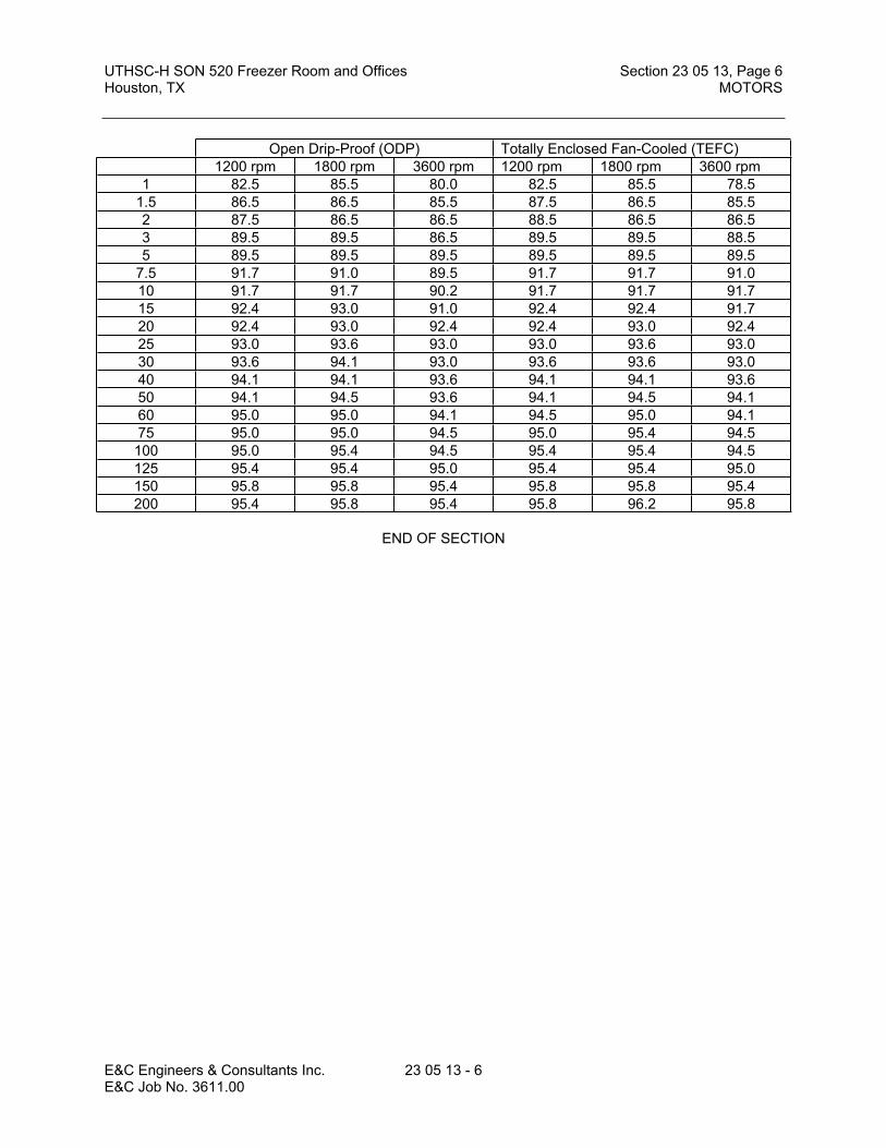
UTHSC-H SON 520 Freezer Room and Offices Section 23 05 13, Page 6Houston, TX MOTORS
E&C Engineers & Consultants Inc. 23 05 13 - 6E&C Job No. 3611.00
END OF SECTION
Open Drip-Proof (ODP) Totally Enclosed Fan-Cooled (TEFC)1200 rpm 1800 rpm 3600 rpm 1200 rpm 1800 rpm 3600 rpm
1 82.5 85.5 80.0 82.5 85.5 78.51.5 86.5 86.5 85.5 87.5 86.5 85.52 87.5 86.5 86.5 88.5 86.5 86.53 89.5 89.5 86.5 89.5 89.5 88.55 89.5 89.5 89.5 89.5 89.5 89.5
7.5 91.7 91.0 89.5 91.7 91.7 91.010 91.7 91.7 90.2 91.7 91.7 91.715 92.4 93.0 91.0 92.4 92.4 91.720 92.4 93.0 92.4 92.4 93.0 92.425 93.0 93.6 93.0 93.0 93.6 93.030 93.6 94.1 93.0 93.6 93.6 93.040 94.1 94.1 93.6 94.1 94.1 93.650 94.1 94.5 93.6 94.1 94.5 94.160 95.0 95.0 94.1 94.5 95.0 94.175 95.0 95.0 94.5 95.0 95.4 94.5
100 95.0 95.4 94.5 95.4 95.4 94.5125 95.4 95.4 95.0 95.4 95.4 95.0150 95.8 95.8 95.4 95.8 95.8 95.4200 95.4 95.8 95.4 95.8 96.2 95.8

UTHSC-H SON 520 Freezer Room and Offices Section 23 05 29, Page 1Houston, TX SLEEVES, FLASHING, SUPPORTS AND ANCHORS
E&C Engineers & Consultants Inc. 23 05 29 - 1 E&C Job No. 3611.00
SECTION 23 05 29SLEEVES, FLASHINGS, SUPPORTS AND ANCHORS
PART 1 GENERAL
1.00 The following sections are to be included as if written herein:
A. Section 23 00 00 – Basic Mechanical Requirements
B. Section 23 05 53 – Mechanical Identification
1.01 SECTION INCLUDES
A. Pipe and equipment hangers and supports
B. Sleeves and seals
1.02 RELATED SECTIONS
A. Section 23 07 16 - Ductwork Insulation
1.03 REFERENCES
A. ASME B31.9 - Building Services Piping
B. ASTM F708 - Design and Installation of Rigid Pipe Hangers
C. MSS SP69 - Pipe Hangers and Supports - Materials, Design and Manufacturer
D. MSS SP89 - Pipe Hangers and Supports - Selection and Application
E. MSS SP89 - Pipe Hangers and Supports - Fabrication and Installation Practices
F. NFPA 13 - Installation of Sprinkler Systems
G. UL 203 - Pipe Hanger Equipment for Fire Protection Service
1.04 SUBMITTALS
A. Submit under provisions of Section 23 00 00.
B. Shop Drawings: Indicate system layout with location and detail of trapeze hangers.
C. Product Data: Provide manufacturers catalog data including load capacity.
D. Design Data: Indicate load carrying capacity of trapeze, multiple pipe, and riser support hangers.
E. Manufacturer's Installation Instructions: Indicate special procedures and assembly of components.

UTHSC-H SON 520 Freezer Room and Offices Section 23 05 29, Page 2Houston, TX SLEEVES, FLASHING, SUPPORTS AND ANCHORS
E&C Engineers & Consultants Inc. 23 05 29 - 2 E&C Job No. 3611.00
1.05 REGULATORY REQUIREMENTS
A. Conform to applicable code for support of plumbing, hydronic, steam and steam condensate piping.
B. Supports for Sprinkler Piping: Shall be in conformance with NFPA 13.
C. Supports for Standpipes: Shall be in conformance with NFPA 14.
PART 2 PRODUCTS
2.01 HANGERS AND SUPPORTS
A. Manufacturers:
1. Grinnell.
2. Kindorf
3. B-Line
4. Power Strut
5. Anvil International
B. Supports, hangers, anchors and guides shall be provided for all horizontal and vertical piping. Shop Drawings shall be provided, indicating locations and details of anchors, guides, expansion loops and joints, hangers, etc. The hanger design shall conform to the ASME Code for Pressure Piping.
C. All auxiliary steel required for supports, anchors, guides, etc. shall be provided by the Mechanical Trades unless specifically indicated to be provided by others.
D. The supports, hangers, anchors, and guides for the chilled water supply and return piping, steam piping, condensate return piping, etc. of the Campus Loop System routed above covered walk shall be provided as indicated on the Drawings.
E. Contractor shall review all Drawings, including Structural Drawings, for details regarding pipe supports, anchors, hangers, and guides.
F. All Supports shall be of type and arrangement to prevent excessive deflection, to avoid excessive bending stresses between supports, and to eliminate transmission of vibration.
G. All rod sizes indicated in this Specification are minimum sizes only. This trade shall be responsible for structural integrity of all supports, anchors, guides, etc. All structural hanging materials shall have a minimum safety factor of 5 built in.
H. Anchor points as indicated on Drawings or as required shall be located and constructed to permit the piping system to take up its expansion and contraction freely in opposite directions away from the anchored points.

UTHSC-H SON 520 Freezer Room and Offices Section 23 05 29, Page 3Houston, TX SLEEVES, FLASHING, SUPPORTS AND ANCHORS
E&C Engineers & Consultants Inc. 23 05 29 - 3 E&C Job No. 3611.00
I. Guide points shall be located and constructed wherever required or indicated on Drawings and at each side of an expansion joint or loop, to permit free axial movement only.
J. Supports, hangers, anchors, and guides shall be fastened to the structure only at such points
where the structure is capable of restraining the forces in the piping system.
K. Other special type of hangers may be employed where so specified or indicated on the Drawings, or where required by the particular conditions. In any case, all hangers must be acceptable to the owner.
L. All electrical conduits shall be run parallel or perpendicular to adjacent building lines. Single conduits running horizontally shall be supported by "Caddy" or "Minerallac" type hangers from adequately sized rods (minimum 1/4") from the building structure. Where multiple conduits are run horizontally, they shall be supported on trapeze of "Unistrut" type channel suspended on rods or bolted to vertical building members. Conduit shall be secured to channel with galvanized "Unistrut" type conduit clamps or stainless steel "Unistrut" type "Uni-Clips.” All hangers shall be fastened to the building structure in the same manner as specified above for pipe hangers. Spacing of hangers shall be adequate for the weight and rigidity of the conduits involved; in any case, no greater than 8' centers. Where feasible, conduits may be fastened to the concrete by one-hole straps thoroughly anchored to the concrete in an approved manner. Flexible conduit shall also be supported in an acceptable manner so as not to interfere with the maintenance of above-ceiling equipment, and to support it from touching the ceiling system. Conduit shall be located so as not to inhibit removal of ceiling tiles.
M. Vertical conduits shall be supported as often as necessary for rigidity by clamps resting on adjacent beams or floor slabs, using a minimum of one support per floor.
N. Perforated strap iron or wire will not, under any circumstances, be acceptable as hanger material.
O. Where specifically noted on the drawings that one material is to be hung from the support of another material due to space restrictions, the hangers shall be sized to properly carry the weight of all items to be supported by such.
P. Vibration Isolation: Resilient hangers shall be provided on all piping connected to rotating equipment (pumps, etc.). Piping or ductwork that may vibrate and create an audible noise shall also be isolated. Spring hangers or supports shall be provided where indicated on the Drawings and/or specified under Section 23 05 48.
Q. Attachment:
1. The load and spacing on each hanger and/or insert shall not exceed the safe allowable load for any component of the support system, including the concrete which holds the inserts. Reinforcement at inserts shall be provided as required to develop the strength required.
2. Inserts shall be of a type which will not interfere with reinforcing as shown on the structural Drawings and which will not displace excessive amounts of structural concrete.
3. All supports shall be designed and installed to avoid interference with other piping, hangers, ducts, electrical conduit, supports, building structures, equipment, etc. All piping shall be installed with due regard to expansion and contraction and the type of hanger method of support, location of support, etc. shall be governed in part by this Specification.

UTHSC-H SON 520 Freezer Room and Offices Section 23 05 29, Page 4Houston, TX SLEEVES, FLASHING, SUPPORTS AND ANCHORS
E&C Engineers & Consultants Inc. 23 05 29 - 4 E&C Job No. 3611.00
4. Hangers shall be attached to the structure as follows:
a) Poured In Place Concrete: Where pipes and equipment are supported under poured in place concrete construction, each hanger rod shall be fitted with a nut at its upper end, which nut shall be set into an Underwriters Laboratories, Inc. listed universal concrete insert placed in the form work before concrete is poured. Where inserts are placed in the bottom faces of concrete joists which are too narrow to provide adequate strength of concrete to hold the insert properly or where a larger insert would require displacement of the bottom joist steel, the hanger rod shall be suspended from the center of a horizontal angle iron, channel iron, I-beam, etc. spanning across two adjacent joists. The horizontal support shall be bolted to nonadjustable concrete inserts of the "spot" type, of physical size small enough to avoid the bottom joist steel.
b) Steel Bar Joists: Where pipes and loads are supported under bar joists, hanger rods may be run through the space between the bottom angles and secured with a washer and two nuts. Where larger lines are supported beneath bar joists, hanger rods shall be secured to angle irons of adequate size; each angle shall span across two or more joists as required to distribute the weight properly and shall be welded to the joists or otherwise permanently fixed thereto.
c) Steel Beams: Where pipes and loads are supported under steel beams, approved type beam clamps shall be used.
d) Pre-Cast Tee Structural Concrete: Hanger supports, anchors, etc. required for mechanical systems attached to the precast, double tee, structural concrete system are to be installed in accord with approved shop Drawings only. Holes required for hanger rods shall be core drilled in the "flange" of the double tee only; impact type tools are not allowed under any circumstances. Core drilling in the "stem" portions of the double tee is not allowed. Holes core drilled through the "flange" for hanger rods shall be no greater than 1/4" larger than the diameter of the hanger rod. Hanger rods shall be supported by means of bearing plates of size and shape acceptable to the Architect/Engineer, with welded double nuts on the hanger rod above the bearing plate. Cinch anchors, lead shields, expansion bolts, and studs driven by explosion charges are not allowed under any circumstances in the lower 15" of each stem and in the "shadow" of the stem on the top side of the "double tees.”
e) If it is necessary to install a method of fastening a hanger after the structure has been installed, then only clamps or drilled anchors shall be used.
Power-actuated fasteners (shooting) will not be acceptable under any circumstances.
Note: Under no circumstances will the use of plastic anchors or plastic expansion shields be permitted for any purpose whatsoever.
5. Power-actuated fasteners (shooting) will not be acceptable under any circumstances.
R. Finishes: All hangers on piping including clevis hangers, rods, inserts, clamps, stanchions, and brackets, shall be dipped in Zinc Chromate Primer before installation. Rods may be galvanized

UTHSC-H SON 520 Freezer Room and Offices Section 23 05 29, Page 5Houston, TX SLEEVES, FLASHING, SUPPORTS AND ANCHORS
E&C Engineers & Consultants Inc. 23 05 29 - 5 E&C Job No. 3611.00
or cadmium plated after threading, in lieu of dipping zinc chromate. Universal concrete inserts shall be cadmium plated.
S. Trapezes: Where multiple lines are run horizontally at the same elevation and grade, they may be supported on trapezes of Kindorf, Uni-Strut, Power Strut, or approved equal, channel-suspended on rods or pipes. Trapeze members including suspension rods shall each be properly sized for the number, size, and loaded weight of the lines they are to support.
T. Miscellaneous: Provide any other special foundations, hangers and supports indicated on the Drawings, specified elsewhere herein; or required by conditions at the site. Hangers and supporting structures for suspended equipment shall be provided as required to support the load from the building structure in a manner acceptable to the Architect/Engineer.
U. Miscellaneous: Provide any other special foundations, hangers and supports indicated on the Drawings, specified elsewhere herein; or required by conditions at the site. Hangers and supporting structures for suspended equipment shall be provided as required to support the load from the building structure in a manner acceptable to the Architect/Engineer.
V. Ductwork supported from the floor: Ductwork supported from the floor shall be done by the same means as that supported from above, but shall include a neoprene vibration isolation spacer to restrict vibration transmission to the structure below.
2.03 ACCESSORIES
A. Hanger Rods: Galvanized mild steel threaded both ends, galvanized threaded one end, or galvanized continuous threaded.
B. Inserts: Malleable iron case of galvanized steel shell and expander plug for threaded connection with lateral adjustment, top slot for reinforcing rods, lugs for attaching to forms; size inserts to suit threaded hanger rods. Suitable concrete inserts for pipe and equipment hangers shall be set and properly located for all pipe and equipment to be suspended from concrete construction. If the inserts are later found not to be in the proper location for the placement of hangers, then drilled anchors shall be installed. Drilled anchors in concrete or masonry shall be submitted for the approval by the Owner.
2.04 WALL, FLOOR AND CEILING PLATES:
A. Except as otherwise noted, provide C.P. (Chrome plated) brass floor and ceiling plates around all pipes, conduits, etc., passing exposed through walls, floors, or ceilings, in any spaces except underfloor and attic spaces. Plates shall be sized to fit snugly against the outside of the pipe or against the insulation on lines which are insulated and positively secured to such pipe or insulation. Plates will not be required for piping where pipe sleeves extend 3/4" above finished floor. All equipment rooms are classified as finished areas. Round and rectangular ducts shall have closure plates (NOT chrome plated) made to fit accurately at all floor, wall and ceiling penetrations. Floor penetrations in exposed (except in stair wells) areas shall be finished using 'bell' fitting to fit pipe or insulation and sleeve and shall be painted to match the pipe. Penetrations in stairwells shall have flat floor plate painted to match pipe.
2.05 SLEEVES
A. General: All openings through all floors, walls, and roofs, etc., regardless of material for the passage of piping, ductwork, conduit, cable trays, etc., shall be sleeved. All penetrations must

UTHSC-H SON 520 Freezer Room and Offices Section 23 05 29, Page 6Houston, TX SLEEVES, FLASHING, SUPPORTS AND ANCHORS
E&C Engineers & Consultants Inc. 23 05 29 - 6 E&C Job No. 3611.00
pass through sleeves. Sleeves shall be set in new construction before concrete is poured, as cutting holes through any part of the concrete will not be permitted unless acceptable to the Architect/Engineer. If a penetration is cored into an existing vertical solid concrete, masonry or stone structure, then the installation of a sleeve will not be necessary.
1. Sleeve material for floors and exterior walls shall be Schedule 40 galvanized steel with welded water stop rings.
2. Sleeves through interior walls to be galvanized sheetmetal with gauge as required by wall fire rating, 20 gauge minimum.
B. The minimum clearance between horizontal penetrations including insulation where applicable, and sleeve shall be 1/4", except that the minimum clearance shall accommodate a Thunderline Link-seal closure where piping exits the building, or penetrates a wall below ground level. Contractor shall be responsible for the accurate location of penetrations in the slab for his pipe, duct, etc. All penetrations shall be of ample size to accommodate the pipe, duct, etc., plus any specified insulation. Void between sleeve and pipe in interior penetrations shall be filled with Nelson Flameseal Firestop or approved equal caulk or putty.
C. Floor sleeves shall extend above the finished floor as detailed on the drawings, except that floor sleeves in stairwells shall be flush with the finished floor. Sleeves in walls shall be trimmed flush with wall surface. Refer to the details on the project drawings. Where the details differ from these specifications, the drawings take precedence.
D. Sleeves for penetrations passing through walls or floors on or below grade shall be removed, if practical, and after the pipes have been installed, the void space around the pipe shall be caulked with a suitable material to effect a waterproof penetration. Note that the practicality of the removal of the sleeve shall be the decision of the Construction Inspector. The decision of the Inspector shall be final.
E. Vermin proofing: The open space around all ductwork, piping, etc., passing through the ground floor and/or exterior walls shall be vermin proofed in a manner acceptable to the Architect/Engineer.
F. Waterproofing: The annular space between a pipe and its sleeve in interior floors shall be filled with polyurethane foam rods 50 percent greater in diameter than the space as backing and fill material and made watertight with a permanent elastic polysulfide compound. Seal both surfaces of floor.
G. Air Plenums: The space around piping, ductwork, etc., passing through air plenums shall be made airtight in a manner acceptable to the Architect/Engineer.
H. Fireproofing: Seal all cable trays, pipe, conduit, duct, etc., penetrations through roof, fire rated walls and floors with a foam or sealant as described below, that will form a watertight, vermin tight barrier that is capable of containing smoke and fire up to 2000 F for two hours. Sealing of cable trays and conduits that extend through rated walls from ends of cable tray shall be done after conductors have been installed. For wet locations, the foam material shall be a silicone RTV foam or an approved equal. For dry locations, a premixed putty equal to Nelson Flameseal Firestop putty may be used.
PART 3EXECUTION
UTHSC-H SON 520 Freezer Room and Offices Section 23 05 29, Page 7Houston, TX SLEEVES, FLASHING, SUPPORTS AND ANCHORS
E&C Engineers & Consultants Inc. 23 05 29 - 7 E&C Job No. 3611.00
3.01 INSTALLATION
A. Install in accordance with manufacturer's instructions.
3.02 INSERTS
A. Provide inserts for placement in concrete formwork.
B. Provide inserts for suspending hangers from reinforced concrete slabs and sides of reinforced concrete beams.
C. Provide hooked rod to concrete reinforcement section for inserts carrying pipe over 4 inches.
D. Where concrete slabs form finished ceiling, locate inserts flush with slab surface.
E. Where inserts are omitted, drill through concrete slab from below and provide through-bolt with recessed square steel plate and nut recessed into and grouted flush with slab.
3.03 SLEEVES
A. Set sleeves in position in formwork. Provide reinforcing around sleeves.
B. Size sleeves large enough to allow for movement due to expansion and contraction. Provide for continuous insulation wrapping.
C. Extend sleeves through floors (except in stairwells) two inches above finished floor level. Sleeves through floors shall have welded waterstop rings. Sleeves shall be sealed watertight to floors and pipe.
D. Where piping, ductwork or conduit penetrates floor, ceiling, or wall, close space between pipe or duct and adjacent work with fire stopping insulation and caulk airtight. Provide close fitting metal collar or escutcheon covers, as appropriate, at both sides of penetration.
E. Install chrome plated steel or stainless steel escutcheons at finished surfaces.
3.04 LOW PRESSURE DUCT SUPPORT SCHEDULE:
A. All horizontal ducts up to and including 40 inches in their greater dimension shall be supported by means of No. 18 U.S. gauge band iron hangers attached to the ducts by means of screws, rivets, or clamps and fastened to above inserts with toggle bolts, beam clamps or other approved means. Duct shall have at least one pair of supports 8' 0" on centers. Clamps shall be used to fasten hangers to reinforcing on sealed ducts.
B. Horizontal ducts larger than 40 inches in their greatest dimension shall be supported by means of hanger rods bolted to angle iron trapeze hangers. Duct shall have at least one pair of supports 8' 0" on centers according to the following:
AngleLength Angle Rod Diameter
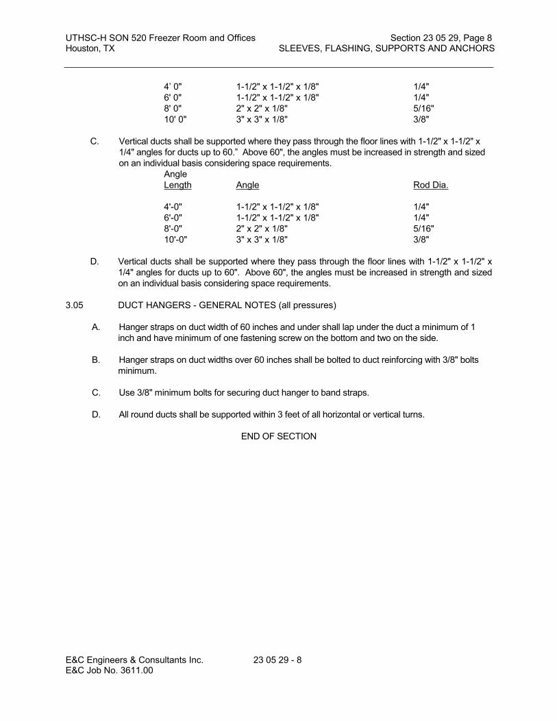
UTHSC-H SON 520 Freezer Room and Offices Section 23 05 29, Page 8Houston, TX SLEEVES, FLASHING, SUPPORTS AND ANCHORS
E&C Engineers & Consultants Inc. 23 05 29 - 8 E&C Job No. 3611.00
4’ 0" 1-1/2" x 1-1/2" x 1/8" 1/4"6' 0" 1-1/2" x 1-1/2" x 1/8" 1/4"8' 0" 2" x 2" x 1/8" 5/16"10' 0" 3" x 3" x 1/8" 3/8"
C. Vertical ducts shall be supported where they pass through the floor lines with 1-1/2" x 1-1/2" x 1/4" angles for ducts up to 60.” Above 60", the angles must be increased in strength and sized on an individual basis considering space requirements.
AngleLength Angle Rod Dia.
4'-0" 1-1/2" x 1-1/2" x 1/8" 1/4"6'-0" 1-1/2" x 1-1/2" x 1/8" 1/4"8'-0" 2" x 2" x 1/8" 5/16"10'-0" 3" x 3" x 1/8" 3/8"
D. Vertical ducts shall be supported where they pass through the floor lines with 1-1/2" x 1-1/2" x 1/4" angles for ducts up to 60". Above 60", the angles must be increased in strength and sized on an individual basis considering space requirements.
3.05 DUCT HANGERS - GENERAL NOTES (all pressures)
A. Hanger straps on duct width of 60 inches and under shall lap under the duct a minimum of 1 inch and have minimum of one fastening screw on the bottom and two on the side.
B. Hanger straps on duct widths over 60 inches shall be bolted to duct reinforcing with 3/8" bolts minimum.
C. Use 3/8" minimum bolts for securing duct hanger to band straps.
D. All round ducts shall be supported within 3 feet of all horizontal or vertical turns.
END OF SECTION

UTHSC-H SON 520 Freezer Room and Offices Section 23 05 48, Page 1Houston, TX VIBRATION ISOLATION
E&C Engineers & Consultants Inc. 23 05 48 - 1 E&C Job No. 3611.00
SECTION 23 05 48
VIBRATION ISOLATION
PART 1 GENERAL
1.01 The following sections are to be included as if written herein:
A. 23 00 00 -- Basic Mechanical RequirementsB. 23 05 29 -- Sleeves, Flashings, Supports and AnchorsC. 23 05 53 -- Mechanical Identification
1.02 WORK INCLUDED
A. Inertia bases.B. Vibration isolation.
1.03 SCOPE OF WORK:
A. Furnish and install all labor, materials, equipment tools and service and perform all operations required in connection with or properly incidental to the construction of complete system of vibration and noise control, as indicated on the Drawings, reasonably implied therefrom or as specified herein, unless specifically excluded.
1.04 REFERENCES
A. ASHRAE - Guide to Average Noise Criteria Curves.
1.05 QUALITY ASSURANCE
A. Maintain ASHRAE criteria for average noise criteria curves for all equipment at full load condition.
1.06 SUBMITTALS
A. Submit shop drawings and product data under provisions of Section 23 00 00.B. Indicate inertia bases on shop drawings.C. Indicate vibration isolator locations, with static and dynamic load on each, on shop drawings
and described on product data.D. Submit manufacturer's installation instructions under provisions of Section 23 00 00.
1.07 CERTIFICATES
A. Submit a certificate from the manufacturer that isolators are properly installed and properly adjusted to meet or exceed specified requirements.
1.08 INTENT OF RESPONSIBILITY:
A. It is the intent of this specification to provide for vibration isolation supports for all equipment, piping, and ductwork as set out below. The transmission of perceptible vibration, structural borne noise, or objectionable air borne noise to occupied areas by equipment installed under this contract will not be permitted. The Contractor shall be held responsible for installing the vibration isolators as specified herein or shown on the drawings or otherwise required to prevent the transmission of vibration which would create objectionable noise levels in occupied areas. The isolation supplier must be a firm capable of dealing effectively with

UTHSC-H SON 520 Freezer Room and Offices Section 23 05 48, Page 2Houston, TX VIBRATION ISOLATION
E&C Engineers & Consultants Inc. 23 05 48 - 2 E&C Job No. 3611.00
vibration and noise characteristics effects and criteria; and one which can provide facilities and capabilities for measuring and evaluating the aforementioned disturbances.
B. All vibration isolation devices, including auxiliary steel bases and pouring forms, shall be designed and furnished by a single manufacturer or supplier who will be responsible for adequate coordination of all phases of this work. Inertia bases shall be included as part of mechanical work. Pads under electrical gear shall be included as part of electrical work. The concrete work shall meet the requirements specified in the General Contract Specifications.
C. The Contractor shall furnish complete submittal data, including Shop Drawings, which shall indicate the size, type, and deflection of each isolator; and the supported weight, disturbing frequency, and efficiency of each isolator proposed; and any other information as may be required for the Architects and Engineers to check the isolator selection for compliance with the specification. All steel bases and concrete inertia bases shall be completely detailed, and shall show completely any reinforcing steel that may be required to provide a rigid base for the isolated equipment. Further, the submittal data shall indicate, clearly, outlined procedures for installing and adjusting the isolators and bases mentioned above.
D. The vibration isolation manufacturer, or his qualified representative, shall be responsible for providing such supervision as may be required to assure correct and complete installation and adjustment of the isolators. Upon completion of the installation and after the system is put into operation and before acceptance by the Owner, the isolation manufacturer or his qualified representative, in company with the Architect or his designated representative, shall make a final inspection and submit his report to the Architects and Engineers, in writing, certifying the correctness of the installation and compliance with approved submittal data. Any discrepancies or maladjustments found shall be so noted in the report. Should any noise or vibration be objectionable to the Owner, Architect or Engineer, a field instrumentation test and measurement must be made to determine the source, cause, and path of any such disturbance. Any variation or noncompliance with these specification requirements is to be corrected by the installing contractor in an approved manner.
E. Vibration isolation devices shall be as manufactured by Mason, Amber/Booth Company, Consolidated Kinetics, Korfund Dynamics Corporation, or approved equal.
PART 2 PRODUCTS
2.01 GENERAL DESIGN FEATURES:
A. All vibration isolators and bases furnished by the Contractor shall be designed for and treated for resistance to corrosion.
B. Steel components shall be PVC coated or phosphated and painted with industrial grade enamel. All nuts, bolts and washers shall be zinc-electroplated or cad-plated. Structural bases shall be thoroughly cleaned of welding slag and primed with zinc-chromate or metal etching primer. A finish coat of industrial grade enamel shall be applied over the primer.
C. All isolators exposed to the weather shall have steel parts PVC coated, hot-dip galvanized or zinc-electroplated plus coating of Neoprene or Bitumastic paint. Aluminum components for outdoor installation shall be etched and painted with industrial grade enamel.
D. Required spring deflections for isolators supporting various items of equipment are shown on the Drawings or tabulated elsewhere in these specifications, but in no case shall be less than one inch. The springs shall be capable of 30% over-travel before becoming solid.
E. Where height-saving brackets for side mounting of isolators are required, the height-saving brackets shall be designed to provide for an operating clearance of 2" under the isolated structure, and designed so that the isolators can be installed and removed when the operating clearance is 2" or less. When used with spring isolators having a deflection of 2-1/2" or more, the height-saving brackets shall be of the pre-compression type to limit exposed bolt length between the top of the isolator and the underneath side of the bracket.
F. All isolators supporting a given piece of equipment shall limit the length of the exposed adjustment bolt between the top and base to a maximum range of 1" to 2".

UTHSC-H SON 520 Freezer Room and Offices Section 23 05 48, Page 3Houston, TX VIBRATION ISOLATION
E&C Engineers & Consultants Inc. 23 05 48 - 3 E&C Job No. 3611.00
G. All isolators supporting a given piece of equipment shall be selected for approximately equal spring deflection.
H. Isolators for equipment installed out-of-doors shall be designed to provide adequate restraint due to normal wind conditions and to withstand wind load of 55 PSF (pounds per square foot) applied to any exposed surface of the equipment without failure.
2.02 ISOLATOR TYPES: Isolator types and required deflections are specified under "Schedule of Isolated Equipment", paragraph 3.02. The isolators shall comply with the following descriptions for each type required on the project:
A. Type 1 - An adjustable, free-standing, open-spring mounting with combination leveling bolt and equipment fastening bolt. The spring(s) shall be rigidly attached to the mounting baseplate and to the spring compression plate. The isolator shall be designed for a minimum Kx/Ky (horizontal to vertical spring rate) of 1.0. A Neoprene pad having a minimum thickness of 1/4" shall be bonded to the baseplate. Baseplates shall be sized to limit pad loading to 100 psi.
B. Type 2 - An aluminum-housed, or cast iron housed, adjustable, spring mounting having telescoping top and bottom sections separated by resilient inserts of Neoprene or other suitable material to limit horizontal motion. The inserts shall be permanently lubricated to minimize vertical friction. Sheet or cast iron housings may be used if they are hot-dip galvanized after fabrication. A Neoprene pad having a minimum thickness of 1/4" shall be bonded to the baseplate.
C. Type 4 - A pad-type mounting consisting of two layers of 3/8" thick, ribbed or waffled, Neoprene pads bonded to a 16 gauge galvanized steel separator plate. Bolting not required. Pads shall be sized for approximately 20 to 40 psi load, or a deflection of 0.10" to 0.16".
D. Type 5 - A spring hanger consisting of a rectangular steel box, coil springs, spring cups, Neoprene impregnated fabric washer, steel washer, and Neoprene insert designed to prevent metal to metal contact between the hanger rod and bottom of the hanger box. The hanger box shall be capable of supporting a load of 200% of rated load without noticeable deformation or failure.
E. Type 6 - A spring hanger, as described in Type 5, with the addition of an elastomeric element at the top of the box for acoustic isolation. The design shall be such to prevent metal - to metal contact between the hanger rod and the top of the hanger box. The elastomeric element shall meet the design requirements for Type 3 mountings.
F. Type 7 - An elastomeric hanger, consisting of a rectangular steel box and an elastomeric isolation element, which shall be of Neoprene or high quality synthetic rubber with anti-ozone and anti-oxidant additive. The elements shall be so designed for approximately 1/4" deflection and loaded so that deflection does not exceed 15% of the free height of the element. The design shall be such as to prevent metal-to-metal contact between the hanger rod and the steel box.
G. Type 8 - 1/4" thick closed cell Neoprene ASTM Grade S.E.C. 44 in sheets cut to fit penetrations, as required.
2.03 BASE TYPES: Base types and required deflections are specified under "Schedule of Isolated Equipment", paragraph 7.8, or are indicated on the Drawings. The bases shall comply with the following descriptions for each type required on the project.
A. Type B-1 - A structural steel fan and motor base with motor side rails and holes drilled to receive the fan and motor. The steel members shall be adequately sized to prevent distortion and misalignment of the drive, and specifically shall be sized to limit deflection of the beam on the drive side to 0.05" due to starting torque. Snubbers to prevent excessive motion on starting or stopping shall be furnished, if required; however, the snubbers shall not be engaged under steady running conditions.
B. Type B-2 - A concrete inertia base, consisting of a perimeter steel pouring forming, reinforcing bars welded in place, bolting templates, anchor bolts, and height-saving brackets

UTHSC-H SON 520 Freezer Room and Offices Section 23 05 48, Page 4Houston, TX VIBRATION ISOLATION
E&C Engineers & Consultants Inc. 23 05 48 - 4 E&C Job No. 3611.00
for side mounting of the isolators. The perimeter steel members shall be structural channels having a minimum depth of 1/12 of the longest span, but not less than 6" deep. The inertia base for pumps shall be at least equal in weight to the pump with its driving motor and be sized for a minimum overlap of 4" around the base of the equipment. Concrete inertia bases for pumps shall be sized to support the suction elbow of end suction pumps and both the suction and discharge elbows of horizontal split-case pumps. The bases shall be T-shaped where necessary to conserve space.
PART 3 EXECUTION
3.01 GENERAL INSTALLATION REQUIREMENTS:
A. Install vibration isolators for motor driven equipment.B. Set steel bases for one inch clearance between housekeeping pad and base. Set concrete
inertia bases for 2 inch clearance. Adjust equipment level.C. Provide spring isolators on piping connected to isolated equipment as follows: Up to 4 inch
diameter, first three points of support; 5 to 8 inch diameter, first four points of support; 10 inch diameter and over, first six points of support. Static deflection of first point shall be twice deflection of isolated equipment.
D. Piping:1. Floor mounted supports shall have the same type of isolator or media as is used for
the nearest isolated equipment connected to the piping.2. The pipe hanger system shall have provisions for all piping to be shimmed or
blocked in place until all connections are made and the system filled with water; then, the isolators adjusted to support the weights, and the shim blocks removed.
3. The first three support points from a piece of isolated equipment shall be of the positioning type and provide not less than the static deflection of the equipment isolators.
4. All springs supporting piping shall be capable of an additional 1/2" deflection prior to complete compression and springs supporting vertical risers shall have provisions for limit stops.
E. Resilient Sleeves:1. Resilient sleeves shall be provided at all points where equipment room walls, floors,
or ceilings are penetrated by ducts, piping, or refrigerant line, etc.F. Fans and Air Handling Units:
1. Such units shall have electrical flexible connections not less than 36" long and fans shall have flexible duct connections with a free length of not less than 8".
3.02 SCHEDULE OF ISOLATED EQUIPMENT:
A. Tabulated below is a schedule of equipment on this project requiring vibration isolation and base isolators of the types listed above. Any equipment, system, construction or condition that may be altered, added, or changed; or that is not specifically considered herein or on the plans shall be treated in a manner that is set out for similar equipment system or construction in order to comply with the above requirements heretofore cited.

UTHSC-H SON 520 Freezer Room and Offices Section 23 05 48, Page 5Houston, TX VIBRATION ISOLATION
E&C Engineers & Consultants Inc. 23 05 48 - 5 E&C Job No. 3611.00
ISOLATOR BASEISOLATOR EQUIP. ISOL.EQUIPMENT TYPE DEFLECTION TYPE
1. Piping 5 1" ---2. Piping in Mechanical Rooms 5 1" ---3. Fan Coil Units 7 1” ---4. All pipe and duct wall penetrations 8 --- ---
END OF SECTION

UTHSC-H SON 520 Freezer Room and Offices Section 23 05 53, Page 1Houston, TX MECHANICAL IDENTIFICATION
E&C Engineers & Consultants Inc. 23 05 53 - 1 E&C Job No. 3611.00
SECTION 23 05 53
MECHANICAL IDENTIFICATION
PART 1 GENERAL
1.01 The following sections are to be included as if written herein:
A. Section 23 00 00 – Basic Mechanical RequirementsB. Section 23 05 29 – Sleeves, Flashings, Supports and Anchors
1.02 SECTION INCLUDES
A. Nameplates.B. Tags.C. Stencils.D. Pipe Markers.
1.03 PRODUCTS INSTALLED BUT NOT FURNISHED UNDER THIS SECTION
A. NONE
1.04 RELATED SECTIONS
A. Section 23 00 00 - Basic Mechanical Requirements.
1.05 REFERENCES
A. ASME A13.1 - Scheme for the Identification of Piping Systems.
1.06 SUBMITTALS
A. Submit under provisions of Section 23 00 00.B. Submit list of wording, symbols, letter size, and color coding for mechanical identification.C. Submit valve chart and schedule, including valve tag number, location, function, and
valve manufacturer's name and model number.D. Product Data: Provide manufacturers catalog literature for each product required.E. Samples: Submit two of each type of label, tag, etc., of the approximate size specified or
implied in the specification.F. Manufacturer's Installation Instructions: Indicate special procedures, and installation.
1.07 PROJECT RECORD DOCUMENTS
A. Submit under provisions of Section 23 00 00.B. Record actual locations of tagged valves.
PART 2 PRODUCTS
2.01 NAMEPLATES
A. Manufacturers:1. Seaton.2. Other acceptable manufacturers offering equivalent products.

UTHSC-H SON 520 Freezer Room and Offices Section 23 05 53, Page 2Houston, TX MECHANICAL IDENTIFICATION
E&C Engineers & Consultants Inc. 23 05 53 - 2 E&C Job No. 3611.00
a. Bradyb. Buntingc. EMED
B. Description: Laminated three-layer plastic with engraved black letters on light contrasting background color.
2.02 TAGS
A. Manufacturers:1. Seaton2. Other acceptable manufacturers offering equivalent products.
a. W.H. Bradyb. Bunting
B. Metal Tags: Brass with stamped letters; tag size minimum 1-1/2 inch (40 mm) diameter with smooth edges.
C. Chart: Typewritten letter size list in anodized aluminum frame.
2.03 PIPE MARKERS
A. Manufacturers:1. Seton2. Other acceptable manufacturers offering equivalent products.
a. W.H. Bradyb. Buntingc. EMED
B. Color: Conform to ASME A13.1.C. Plastic Pipe Markers: Factory fabricated, flexible, semi- rigid plastic, preformed to fit
around pipe or pipe covering; minimum information indicating flow direction arrow and identification of fluid being conveyed.
D. Plastic Tape Pipe Markers: Flexible, vinyl film tape with pressure sensitive adhesive backing and printed markings.
E. Underground Plastic Pipe Markers: Bright colored continuously printed plastic ribbon tape, minimum 6 inches (150 mm) wide by 4 mil (0.10 mm) thick, manufactured for direct burial service.
2.04 CEILING TACKS
A. Manufacturers:1. Seton2. Other acceptable manufacturers offering equivalent products.
a. W.H. Bradyb. Buntingc. EMED
B. Description: Steel with 3/4 inch (20 mm) diameter color coded head.C. Color code as follows:
1. Yellow - HVAC equipment2. Red - Fire dampers/smoke dampers3. Green - Plumbing valves4. Blue - Heating/cooling valves
2.05 General: The Contractor shall make it possible for the personnel operating and maintaining the equipment and systems in this project to readily identify the various pieces of equipment, valves, piping, etc., by marking them. All items of equipment such as fans, pumps, etc., shall be clearly marked using engraved nameplates as hereinafter specified. The item of equipment shall

UTHSC-H SON 520 Freezer Room and Offices Section 23 05 53, Page 3Houston, TX MECHANICAL IDENTIFICATION
E&C Engineers & Consultants Inc. 23 05 53 - 3 E&C Job No. 3611.00
indicate the same number as shown on the Drawings. For example, pumps will be identified as 3A, 3B, 3C, etc.; exhaust fans will be E-1, E-2, etc.; supply fans will be S-1, S-2, etc.
2.06 Mechanical: All items of mechanical equipment shall be identified by the attachment of engraved nameplates constructed from laminated phenolic plastic, at least 1/16" thick, 3-ply, with black surfaces and white core. Engraving shall be condensed Gothic, at least 1/2" high, appropriately spaced. Nomenclature on the label shall include the name of the item, its mark number, area, space, or equipment served, and other pertinent information. Equipment to be labeled shall include but not be limited to the following:
Exhaust FansZoning Boxes/Valves Fire/Smoke dampersAir Conditioning Control Miscellaneous - similarPanels and Switches and/or related items
2.07 Piping: Pipe markers and arrow markers also shall be provided on but not limited to the piping of the following systems:
Primary Chilled Water Supply Primary Chilled Water Return Plumbing PipingSystems
Roof Drain Heating Hot Water Supply Heating Hot WaterReturn
Domestic Hot Domestic Hot Domestic ColdWater Supply Water Return Water Supply
2.08 Electrical: Nameplates shall be 2 or 3 ply laminated plastic, a minimum of 3/32" thick, such that letters will be white on black background. Letters shall be similar to Roman Gothic of a size that is legible and appropriate to the application. Attachment of nameplates shall be by screws. Rivets or adhesives are not acceptable.
A. Electrical equipment to be identified includes: All switchgear, distribution panels, transformers, motor control centers, panelboards, disconnect switches, starters, contactors and time switches.
B. Nameplates on distribution panels, motor control centers and panelboards shall give voltage characteristics.Example:
PANEL LA120/208V, 3 PH, 4 Wserved from .
C. Individual circuit breakers in distribution panels, individual units in motor control centers, disconnecting means, and motor starters, shall have nameplates showing the load served.
D. Branch circuit panelboards shall have neatly typed circuit directories behind clean plastic. Identify circuits by room numbers. Room numbers shall be those finally selected by the Owner; not necessarily those given on contract Drawings. If a circuit serves more than one room, list each room. Spares and spaces shall be indicated with erasable pencil; not typed.
2.09 The Contractor shall prepare and install, in a suitable glazed frame, typewritten valve charts giving the number, location and function of each line valve installed under this Contract. Each valve shall be numbered on these charts in accordance with the system of which it is a part of its location. For example, valves in different systems would be designated as follows:
HPS-1-3 High Pressure Steam 1st Level - Valve No. 3

UTHSC-H SON 520 Freezer Room and Offices Section 23 05 53, Page 4Houston, TX MECHANICAL IDENTIFICATION
E&C Engineers & Consultants Inc. 23 05 53 - 4 E&C Job No. 3611.00
CHS-2-4 Chilled Water Supply 2nd Level - Valve No. 4
2.10 Valve Tags:
A. The Contractor shall provide and install identification tags lettered and numbered to correspond to the information shown on the charts described above. These tags are to be affixed to all valves except simple service and drain valves located within 10' and within sight of the device or equipment served. For example, it would not be expected that valves at a pressure reducing station in a machine room would be tagged. These tags shall be 1/8" thick brass discs, 1 1/2" in diameter. Each tag shall be attached to its valve with copper clad annealed iron wire or other approved material.
B. Valves at water headers and steam PRV stations, valves associated with condensate, gas, water meters, and other valves as specified shall also be tagged with standardized color coded plastic tags. These tags shall be 2 1/2" wide by 1 1/2" high with these color codings: Red = normally closed; Green = normally open; Blue = open in winter, closed in summer; and Yellow = closed in winter, open in summer. Tags should be engraved on both sides.
2.11 In addition, pipe runs throughout the building including those above lift out ceilings, under floor, and those exposed to view when access doors or access panels are opened shall be identified by means of Seton Setmark or Brady Mechanical Pipe Markers. Concealed areas, for purposes of this identification section, are those areas which cannot be seen except by demolition of the building elements. In addition to the pipe markers, arrow markers shall be used to indicate direction of flow. The following specific instructions shall apply to the application of these markers:
A. Provide a pipe marker at each valve to indicate proper identification of pipe contents. Where several valves exist on one header, it is necessary to mark only the header.
B. Provide an arrow marker with each pipe marker pointing away from the pipe marker to indicate direction of flow.
C. Provide a double ended arrow marker when flow can be in either or both directions.D. Provide a pipe marker and an arrow marker at every point of pipe entry or exit where line
goes through a wall or service column.E. Provide pipe markers and arrow markers at intervals not exceeding 50 feet.F. Markers shall be located on the two lower quarters of the pipe where view is
unobstructed.G. Use Seton Setmark Type SNA or Brady snap-on type identification for all piping systems,
3/4" thru 6". For piping systems larger than 6", use Seton or Brady strap on markers. H. Pipe Markers shall conform to ANSI A 13.1-1981 "Scheme for the Identification of Piping
Systems". Arrow markers must have same ANSI background colors as their companion pipe markers, or be incorporated into the pipe identification marker.
I. Locate markers so as to be visible from floor.
2.12 Specials: Refer to special requirements noted in the various sections hereinafter bound.
PART 3 EXECUTION
3.01 PREPARATION
A. Degrease and clean surfaces to receive adhesive for identification materials.B. Prepare surfaces in accordance with Section 09 91 00 for stencil painting.
3.02 INSTALLATION

UTHSC-H SON 520 Freezer Room and Offices Section 23 05 53, Page 5Houston, TX MECHANICAL IDENTIFICATION
E&C Engineers & Consultants Inc. 23 05 53 - 5 E&C Job No. 3611.00
A. Install plastic nameplates with corrosive-resistant mechanical fasteners, or adhesive. Apply with sufficient adhesive to ensure permanent adhesion and seal with clear lacquer.
B. Install tags with corrosion resistant chain.C. Apply stencil painting in accordance with Section 09 91 00.D. Install plastic pipe markers in accordance with manufacturer's instructions.E. Install plastic tape pipe markers complete around pipe in accordance with manufacturer's
instructions.F. Install underground plastic pipe markers 6 to 8 inches (150 to 200 mm) below finished
grade, directly above buried pipe.G. Identify air handling units, pumps, heat transfer equipment, tanks, and water treatment
devices with plastic nameplates. Small devices, such as in-line pumps, may be identified with tags.
H. Identify control panels and major control components outside panels with plastic nameplates.
I. Identify thermostats relating to terminal boxes or valves with nameplates.J. Identify valves in main and branch piping with tags.K. Identify air terminal units and radiator valves with numbered tags.L. Tag automatic controls, instruments, and relays. Key to control schematic.M. Provide ceiling tacks to locate valves, dampers or other concealed equipment above
T-bar type panel ceilings. Locate in corner of panel closest to equipment.
END OF SECTION


UTHSC-H SON 520 Freezer Room and Offices Section 23 05 93, Page 1Houston, TX SYSTEM TESTING ADJUSTING AND BALANCING (TAB)
E&C Engineers & Consultants Inc. 23 05 93 - 1 E&C Job No. 3611.00
SECTION 23 05 93
SYSTEM TESTING, ADJUSTING AND BALANCING
PART 1 GENERAL
1.01 The following sections are to be included as if written herein:
A. 23 00 00 -- Basic Mechanical RequirementsB. 23 05 29 -- Sleeves, Flashings, Supports and AnchorsC. 23 05 53 -- Mechanical Identification
1.02 SUMMARY
A. Testing, adjusting and balancing (TAB) of the air conditioning systems and related ancillary equipment will be performed by an impartial technically qualified TAB firm selected and employed by the Owner, separate and apart from the construction contract.
B. The firm shall be capable of performing the services specified at the location of the facility described within the time specified, of preparing and submitting the detailed report of the actual field work performed, and following up the basic work as may be required.
1.03 QUALIFICATIONS
A. The Firm shall be one which is organized to provide professional services of this specified type in the State of Texas and as a minimum shall have one (1) professional engineer licensed in the State of Texas, with current registration, to perform such professional services. This engineer shall be personally responsible for developing the job site data as required in the test procedures outlined in these Specifications.
B. The Firm shall have operated a minimum of five (5) years under its current Firm name, and shall be in good standing with the State of Texas, Franchise Tax Board. The firm shall submit their full incorporated name, Charter Number and Taxpayer's I.D. Number for proper verification of the firm's status.
C. The Firm shall be capable of providing a performance bond, by a bonding company licensed to do business in the State of Texas, if determined by the Owner that such a bond is required. The amount of the bond which may be required shall be equal to the cost of the proposal submitted, or in the case of more than one proposal, the sum of all such proposals and any awarded work in progress.
D. All personnel used on the job site shall be either professional engineers or engineering technicians, who shall have been permanent, full time employees of the firm for a minimum of six (6) months prior to the start of work for this specific project.
E. The TAB firm shall submit biographical data on the individual proposed to directly supervise the TAB work, as well as other personnel scheduled to perform the technical work under the contract. It shall also submit a background record of at least five years of specialized experience in the field of air hydronic system balancing, and shall possess properly calibrated instrumentation. The supervisory personnel for the TAB firm shall be registered engineers in the mechanical field and all of the employees used in the TAB firm shall be permanent, full-time employees of the firm.
1.04 REFERENCES
A. AABC - National Standards for Testing and Balancing Heating, Ventilating, and Air Conditioning Systems, Sixth Edition 2002.
B. ASHRAE - 2007 HVAC Applications Chapter 37: Testing, Adjusting and Balancing.C. ANSI/ASHRAE Standard 111-2008 - Practices for Measurement, Testing, Adjusting and
Balancing of Buildings, Heating, Ventilation, Air Conditioning and Refrigeration Systems.

UTHSC-H SON 520 Freezer Room and Offices Section 23 05 93, Page 2Houston, TX SYSTEM TESTING ADJUSTING AND BALANCING (TAB)
E&C Engineers & Consultants Inc. 23 05 93 - 2 E&C Job No. 3611.00
1.05 DOCUMENTS
A. The TAB firm shall, as a requirement of the TAB contract, arrange with the Architect to compile one set of mechanical specifications, all pertinent change orders, and the following:1. One complete set of Drawings less the structural sheets.2. One set of mechanical floor plans of the conditioned spaces. These Drawings shall
be ozalid type (blue or black on light background) reproductions to facilitate marking.B. Approved submittal data on equipment installed, and related changes as required to
accomplish the test procedures outlined in Paragraphs 1.06 through 1.10 of this Specification will be available through the Construction Inspector.
1.06 RESPONSIBILITIES OF THE TAB FIRM
A. The TAB personnel shall check, adjust, and balance the components of the air conditioning system which will result in optimal noise, temperature, and airflow conditions in the conditioned spaces of the building while the equipment of the system is operating economically. This is intended to be accomplished after the system components are installed and operating as provided for in the contract documents. It is the responsibility of the Mechanical Contractor to place the equipment into service. Variable air volume systems shall be balanced in accordance with AABC Standard, Latest Edition.
B. Liaison and Early Inspection:1. The TAB firm personnel on the job shall act as liaison between the Owner, Architect
and Contractor. The following reviews (observations) and tests shall be performed by the TAB Agency:a. During the design stage, before the documents are finalized, review the
mechanical drawings and specifications for balanceability and provide commentary.
b. During construction, review all HVAC submittals such as control diagrams, air handling devices, etc., that pertain to commissioning work and balanceability.
c. Allow for a fixed number of trips to the project site, over and above those required for testing and balancing for inspection of installation of the mechanical piping systems, sheet metal work, temperature controls and other component parts of the heating, air conditioning and ventilating systems during the construction stage. These inspections shall be made prior to and/or at the above ceiling inspection. Commentary will be provided to the RCM of each observation.
d. Test one (1) 8" single duct terminal box for performance capability and leakage as described in Section 23 36 00.. The shipment of the box to the TAB Agency's lab will be at the manufacturer's cost and the test period will be for three (3) weeks from receipt of the box. Submittal data will not be approved until box testing passes. If the sample box is rejected for any reason the second test will be at the Contractor's cost and the time allowed will restart when the box is received at the TAB Agency.
e. Test one (1) 8" fan powered box for performance capability and leakage as described in Section 23 36 00A.. The shipment of the box to the TAB Agency's lab will be at the manufacturer's cost and the test period will be for three (3) weeks from receipt of the box. Submittal data will not be approved until box testing passes. If the sample box is rejected for any reason the second test will be at the Contractor's cost and the time allowed will restart when the box is received by the TAB agency.
f. Test 10% of the single and dual duct boxes for casing and damper leakage when the shipment arrives at the project site. All testing (except for the initial boxes) shall be performed on site.

UTHSC-H SON 520 Freezer Room and Offices Section 23 05 93, Page 3Houston, TX SYSTEM TESTING ADJUSTING AND BALANCING (TAB)
E&C Engineers & Consultants Inc. 23 05 93 - 3 E&C Job No. 3611.00
Boxes requiring re-testing will be charged to the Contractor at the unit price provided to the Owner.
2. During the balancing process, as abnormalities and malfunctions of equipment or components are discovered by the TAB personnel, the Construction Inspector shall be advised in writing so that the condition can be corrected by the Mechanical Contractor. The written document need not be formal, but must be understandable and legible. Data from malfunctioning equipment shall not be recorded in the final TAB report. The TAB firm shall not instruct or direct the Contractor in any of the work, but will make such reports as are necessary to the Owner.
1.06 FINAL AIR BALANCEA. General: When systems are complete and ready for operation, the TAB Consultant will
perform a final air balance for all air systems and record the results. The outside, supply, exhaust and return air volume for each air handling unit, supply fan and exhaust fan and the supply, exhaust or return air volume for each distribution device shall be adjusted to within +5% of the value shown on the drawings. Air handling unit and fan volumes shall be adjusted by changing fan speed and adjusting volume dampers associated with the unit. Air distribution device volume shall be adjusted using the spin-in tap damper for flexible duct connected devices and the device OBD for duct connected devices. Air distribution devices shall be balanced with air patterns as specified. Duct volume dampers shall be adjusted to provide air volume to branch ducts where such dampers are shown. The general scope of balancing by the TAB Consultant will include, but is not limited to, the following:1. Filters: Check air filters and filter media and balance only system with essentially
clean filters and filter media. The Division 23 Contractor shall install new filters and filter media prior to the final air balance.
2. Blower Speed: Measure RPM at each fan or blower to design requirements. Where a speed adjustment is required, the Division 23 Contractor shall make any required changes.
3. Ampere Readings: Measure and record full load amperes for motors.4. Static Pressure: Static pressure gains or losses shall be measured across each
supply fan, cooling coil, heating coil, return air fan, air handling unit filter and exhaust fan. These readings shall be measured and recorded for this report at the furthest air device or terminal unit from the air handler supplying that device. Static pressure readings shall also be provided for systems which do not perform as designed.
5. Equipment Air Flow: Adjust and record exhaust, return, outside and supply air CFM(s) and temperatures, as applicable, at each fan, blower and coil.
6. Coil Temperatures: Set controls for full cooling and for full heating loads. Read and record entering and leaving dry bulb and wet bulb temperatures (cooling only) at each cooling coil, heating coil and HVAC terminal unit. At the time of reading record water flow and entering and leaving water temperatures (In variable flow systems adjust the water flow to design for all the above readings).
7. Zone Air Flow: Adjust each zone of multizone units, each HVAC terminal unit and air handling unit for design CFM.
8. Outlet Air Flow: Adjust each exhaust inlet and supply diffuser, register and grille to within +5% of design air CFM. Include all terminal points of air supply and all points of exhaust. Note: For Labs and Rooms that are negative exhaust air flow shall be set to design +10% and supply to design -5%. Positive areas will have opposite tolerances.
9. Pitot Tube Traverses: For use in future troubleshooting by maintenance personnel, all exhaust ducts, main supply ducts and return ducts shall have air velocity and volume measured and recorded by the traverse method. Locations of these traverse test stations shall be described on the sheet containing the data.
10. Maximum and minimum air flow on terminal boxes.
1.07 FINAL CHILLED AND HEATING BALANCE

UTHSC-H SON 520 Freezer Room and Offices Section 23 05 93, Page 4Houston, TX SYSTEM TESTING ADJUSTING AND BALANCING (TAB)
E&C Engineers & Consultants Inc. 23 05 93 - 4 E&C Job No. 3611.00
A. General: When systems are completed and ready for operation, the TAB Consultant will perform a final water balance for each chilled and hot water system. The general scope of balancing by the TAB Consultant will include, but not be limited to, the following:1. Adjusted System Tests: Adjust balancing valves at each coil and heat exchanger
for design flow, +5%. Adjust balancing valves at pumps to obtain design water flow. Record pressure rise across pumps and GPM flow from pump curve. Permanently mark the balanced position for each valve (Note: If discharge valves on the pumps are used for balancing record the head being restricted by the valves).
2. Temperature Readings: Read and record entering and leaving water temperature at each water coil, converter and heat exchanger. Adjust as necessary to secure design and conditions. Provide final readings at all thermometer well locations.
3. Pressure Readings: Water pressure shall be recorded at all gauge connections. Pressure readings at coils and pumps shall be related to coil and pump curves in terms of GPM flow through flow measuring status, if provided and installed, at each air handler. The flow of water through all water coils shall be adjusted by manipulating valves until the rated pressure drops across each coil is obtained and total water flow is verified by flow measuring status. For coils equipped with 3 way valves, the rated pressure drop shall first be adjusted through the coils. The bypass valve shall then be adjusted on each coil until an equal pressure drop between supply and return connections is the same as with the flow through the coil.
4. Ampere Readings: Reading and record full load amperes for each pump motor.
1.08 TESTING OF TEMPERATURE CONTROL SYSTEMS
A. In the process of performing the TAB work, the TAB Agency shall:1. Work with the temperature control contractor to ensure the most effective total
system operation within the design limitations, and to obtain mutual understanding of intended control performance.
2. Verify that all control devices are properly connected.3. Verify that all dampers, valves and other controlled devices are operated by the
intended controller.4. Verify that all dampers and valves are in the position indicated by the controller
(open, closed or modulating).5. Verify the integrity of valves and dampers in terms of tightness of close-off and full-
open positions. This includes dampers in multizone units, terminal boxes and fire/smoke dampers.
6. Observe that all valves are properly installed in the piping system in relation to direction of flow and location.
7. Observe the calibration of all controllers.8. Verify the proper application of all normally opened and normally closed valves.9. Observe the locations of all thermostats and humidistats for potential erratic
operation from outside influences such as sunlight, drafts or cold walls.10. Observe the locations of all sensors to determine whether their position will allow
them to sense only the intended temperatures or pressures of the media. Control Contractor will relocate as deemed necessary by the TAB Agency.
11. Verify that the sequence of operation for any control mode is in accordance with approved shop drawings and specifications. Verify that no simultaneous heating and cooling occurs.
12. Verify that all controller setpoints meet the design intent.13. Check all dampers for free travel.14. Verify the operation of all interlock systems.15. Perform variable volume system verification to assure the system and its
components track with changes from full flow to minimum flow.16. Warm/cool adjust setting should be set to +/-0 by the TAB and JCI for owner
manipulation in the future. No calibration shall be necessary.

UTHSC-H SON 520 Freezer Room and Offices Section 23 05 93, Page 5Houston, TX SYSTEM TESTING ADJUSTING AND BALANCING (TAB)
E&C Engineers & Consultants Inc. 23 05 93 - 5 E&C Job No. 3611.00
B. A systematic listing of the above testing and verification shall be included in the final TAB report.
1.09 REPORTS
A. The activities described in this section shall culminate in a report to be provided in a single (1) bound copy to the RCM and six (6) electronic versions on CD or USB drive.. Neatly type and arrange data. Include with the data the date tested, personnel present, weather conditions, nameplate record of test instrument and list all measurements taken after all corrections are made to the system. Record all failures and corrective action taken to remedy incorrect situation. The intent of the final report is to provide a reference of actual operating conditions for the Owner's operations personnel.
B. All measurements and recorded readings (of air, water, electricity, etc.) that appear in the reports must have been made onsite by the permanently employed technicians or engineers of the firm.
C. At the option of the Construction Inspector, all data sheets tabulated each day by TAB personnel shall be submitted for initial by the Construction Inspector. Those work sheets so initialed, or copies thereof, shall be presented as a supplement to the final TAB report.
D. Submit reports on forms approved by the Owner & Engineer which will include the following information as a minimum:1. Title Page
a. Company Nameb. Company Addressc. Company telephone numberd. Project namee. Project locationf. Project Managerg. Project Engineerh. Project Contractori. Project Identification Number
2. Instrument Lista. Instrumentb. Manufacturerc. Modeld. Serial Numbere. Rangef. Calibration dateg. What test instrument was used for
3. Fan Data (Supply and Exhaust)a. Locationb. Manufacturerc. Modeld. Air flow, specified and actuale. Total static pressure (total external), specified and actualf. Inlet pressureg. Discharge pressureh. Fan RPM
4. Return Air/Outside Air Data (If fans are used, same data as for 3 above)a. Identification/locationb. Design return air flowc. Actual return air flowd. Design outside air flowe. Return air temperaturef. Outside air temperatureg. Required mixed air temperature

UTHSC-H SON 520 Freezer Room and Offices Section 23 05 93, Page 6Houston, TX SYSTEM TESTING ADJUSTING AND BALANCING (TAB)
E&C Engineers & Consultants Inc. 23 05 93 - 6 E&C Job No. 3611.00
h. Actual mixed air temperature5. Electric Motors
a. Manufacturerb. HP/BHPc. Phase, voltage, amperage, nameplate, actuald. RPMe. Service factorf. Starter size, heater elements, rating
6. V-Belt Drivea. Identification/locationb. Required driven RPMc. Driven sheave, diameter and RPMd. Belt, size and quantitye. Motor sheave, diameter and RPMf. Center-to-center distance, maximum, minimum and actual
7. Duct Traversea. System zone/branchb. Duct sizec. Aread. Design velocitye. Design air flowf. Test velocityg. Test air flowh. Duct static pressurei. Air temperaturej. Air correction factor
8. Air Monitoring Station Dataa. Identification/locationb. Systemc. Sized. Areae. Design velocityf. Design air flowg. Test velocityh. Test air flow
9. Air Distribution Test Sheeta. Air terminal numberb. Room number/locationc. Terminal typed. Terminal sizee. Area factorf. Design velocityg. Design air flowh. Test (final) velocityi. Test (final) air flow
10. Cooling Coil Dataa. Identification/numberb. Locationc. Serviced. Manufacturere. Entering air DB temperature, design and actualf. Entering air WB temperature, design and actualg. Leaving air DB temperature, design and actualh. Leaving air WB temperature, design and actuali. Water pressure flow, design and actual

UTHSC-H SON 520 Freezer Room and Offices Section 23 05 93, Page 7Houston, TX SYSTEM TESTING ADJUSTING AND BALANCING (TAB)
E&C Engineers & Consultants Inc. 23 05 93 - 7 E&C Job No. 3611.00
j. Water pressure drop, design and actualk. Entering water temperature, design and actuall. Leaving water temperature, design and actualm. Air pressure drop, design and actual
11. Heating Coil Dataa. Identification/numberb. Locationc. Serviced. Manufacturere. Air flow, design and actualf. Water flow, design and actualg. Water pressure drop, design and actualh. Entering water or steam temperature, design and actuali. Leaving water temperature, design and actualj. Entering air temperature, design and actualk. Leaving air temperature, design and actuall. Air pressure drop, design and actual
12. Control verification indicating date performed and any abnormalities identified.a. Point Location/Description and verification back to graphicsb. EMS Readout (Setpoint and Actual)c. Actual Readoutd. Interlockse. Alarmsf. Sequences of Operation
END OF SECTION


UTHSC-H SON 520 Freezer Room and Offices Section 23 05 93.A, Page 1Houston, TX SYSTEM PREPARATION FOR TESTING, ADJUSTING AND BALANCING
E&C Engineers & Consultants Inc. 23 05 93.A - 1 E&C Job No. 3611.00
SECTION 23 05 93.A
SYSTEM PREPARATION FOR TESTING, ADJUSTING AND BALANCING
PART 1 GENERAL
1.01 The following sections are to be included as if written herein:
A. Section 23 00 00 – Basic Mechanical RequirementsB. Section 23 05 29 – Sleeves, Flashings, Supports and AnchorsC. Section 23 05 53 – Mechanical Identification
1.02 SUMMARY
A. Perform all work required to prepare the building HVAC systems for testing, adjusting and balancing indicated by the Contract Documents as follows:1. Responsibilities of project contractor.2. Preparation for balancing of air systems.3. Preparation for balancing of hydronic and steam systems.
B. The scope of the TAB work as defined in Section 23 05 93 is indicated in order that the Contractor will be advised of the coordination, adjustment, and system modification which will be required under the project work in order to complete the Owner's requirements for final TAB. The TAB firm will not have a contractual relationship with any Contractor referred to herein, but will be responsible to the Construction Inspector and the Owner for the satisfactory execution of the TAB work. The Contractor in his original bid shall allow for the costs required to cover all work which may be required in the TAB phases as defined herein and as may be necessary for the completion of the TAB work as defined by the TAB firm.
1.03 RELATED SECTIONS
A. Section 23 00 00 - Basic Mechanical Requirements.B. Section 23 73 00 – Fan Coil UnitsC. Section 23 31 00 - Ductwork.D. Section 23 33 00 - Ductwork Accessories.E. Section 23 09 23 - Direct Digital Control Systems.F. Section 23 05 93 - System Testing, Adjusting & Balancing.
1.04 SCOPE OF WORK
A. Testing, adjusting, and balancing (TAB) of the air conditioning systems and related ancillary equipment will be performed by an impartial technically qualified TAB firm selected and employed directly by the Owner, separate and apart from the Construction Contract. However, the preparation for and corrections necessary for the Testing, Adjusting and Balancing of these systems, as described herein, are the responsibility of the Contractor.
B. As a part of this project Construction Contract, the Contractor shall make any changes or replacements to the sheaves, belts, dampers, valves, etc. required for correct balance as advised by the TAB firm, at no additional cost to the Owner.
C. The Contractor shall provide and coordinate the services of qualified, responsible Subcontractors, suppliers and personnel as required to correct, repair, and/or replace any and all deficient items or conditions found during the course of this project, including the testing, adjusting and balancing period.
D. In order that all systems may be properly tested, balanced, and adjusted as required herein by these Specifications, the Contractor shall operate said systems at his expense for the length of time necessary to properly verify their completion and readiness for TAB. This

UTHSC-H SON 520 Freezer Room and Offices Section 23 05 93.A, Page 2Houston, TX SYSTEM PREPARATION FOR TESTING, ADJUSTING AND BALANCING
E&C Engineers & Consultants Inc. 23 05 93.A - 2 E&C Job No. 3611.00
length of time shall be subject to the approval of the Construction Inspector.E. Project Contract completion schedules shall allow for sufficient time to permit the completion
of TAB services prior to Owner occupancy. The contractor shall allow adequate time for the testing and balancing activities of the owner provided services, during the construction period, and prior to Substantial Completion as defined in the Uniform General Conditions of this Construction Document.
F. The Drawings and Specifications indicate valves, dampers and miscellaneous adjustment devices for the purpose of adjustment to obtain optimum operating conditions, and it will be the responsibility of the Contractor to install these devices in a manner that will leave them accessible and readily adjustable. Should any such device not be readily accessible, the Contractor shall provide access as requested by the TAB firm. Also, any malfunction encountered by TAB personnel and reported to the Contractor or the Construction Inspector shall be corrected by the Contractor immediately so that the balancing work can proceed with the minimum of delays.
1.05 RESPONSIBILITIES OF THE PROJECT CONTRACTOR:
A. The Contractor shall:1. Have the building and air conditioning systems in complete operational readiness for
TAB work to begin.2. The contractor shall allow sufficient time for the TAB firm to perform his contracted
work within the construction schedule. The contractor shall complete his work by systems or floors whichever is the most efficient for scheduling. After awarding of the contract and the contractor has developed a construction schedule, a TAB coordination meeting shall be held at the RCM's office with the TAB agency, the general contractor and his primary subcontractors (i.e. mechanical, electrical, building automation etc.) to develop a testing schedule for the project. The contractor shall submit copies of the proposed schedule two (2) weeks prior to this meeting to the RCM and TAB Agency.The following are minimum time requirements:TAB Agency will provide Engineer with tentative schedules for each area, floor and/or system to be included in this section.Note: The hot water and chilled water systems must be 100% complete to balance. The air systems are pressure independent and can be balanced by floors, risers, systems, etc., but once the total system is complete the total flows and system tracking will require finalization. Lab certification will be performed when the building is 100% operational and balanced.
3. Promptly correct deficiencies of materials and workmanship identified as delaying completion of TAB work.
4. Be responsible for any added costs to the Owner resulting from his failure to have the building and air conditioning systems ready for TAB when scheduled, or from his failure to correct deficiencies promptly.
B. Complete operational readiness of the building requires that construction status of the building shall permit the closing of doors, windows, ceilings installed, etc., to obtain simulated or projected operating conditions.
C. Complete operational readiness of the air conditioning systems also requires that the following be accomplished:1. Air Distribution Systems:
a. Verify installation for conformity to design. All supply, return and exhaust ducts terminated and pressure tested for leakage as required by the Specification.
b. All volume, smoke and fire/smoke dampers are properly located and functional. Dampers serving requirements of minimum and maximum outside, return and relief air shall provide tight closure and full opening, smooth and free operation.

UTHSC-H SON 520 Freezer Room and Offices Section 23 05 93.A, Page 3Houston, TX SYSTEM PREPARATION FOR TESTING, ADJUSTING AND BALANCING
E&C Engineers & Consultants Inc. 23 05 93.A - 3 E&C Job No. 3611.00
c. All supply, return, exhaust and transfer grilles, registers, diffusers and terminal devices installed.
d. Air handling systems, units and associated apparatus, such as heating and cooling coils, filter sections, access doors, etc., shall be blanked and/or sealed to eliminate excessive bypass or leakage of air.
e. All fans (supply, return and exhaust) operating and verified for freedom from vibration, proper fan rotation and belt tension; heater elements in motor starters to be of proper size and rating; record motor amperage and voltage on each phase at start-up and running, and verify they do not exceed nameplate ratings.
f. All single and/or double duct variable and constant volume terminal units ("mixing boxes") shall be installed and functional (i.e. controls functioning).
2. Water Circulating Systems:a. Check and verify pump alignment and rotation.b. Open all valves to their full open position, close bypass stop valves. Set
mixing valves to full-flow through systems components. After the system is flushed and checked for proper operation, remove and clean all strainers. The Contractor shall repeat the operation until circulating water is clean.
c. Record each pump motor amperage on each phase and voltage after reaching rated speed. Readings shall not exceed nameplate rating.
d. Verify that the electrical heater elements are of the proper size and rating.e. In preparation of TAB all water circulating systems shall be full and free of
air, expansion tanks shall be set for proper water level, and all air vents shall be installed at high points of systems and operating freely. Systems shall be cleaned and flushed. Chemicals shall be added to closed systems to treat piping and inhibit corrosion.
f. Check and set operating parameters of the heat exchangers and control devices to the design requirements.
3. Automatic Controls:a. The Contractor shall schedule a meeting with the Engineer, Control
Contractor, TAB firm and Owner's representative for a pre-submittal review to establish that their interpretations of the sequences of operation are correct.
b. Verify that all control components are installed in accordance with project requirements and are functional, including all electrical interlocks, dampers sequences, air and water resets, fire and freeze stats, high and low temperature thermostats, safeties, etc.
c. Verify that all controlling instruments are calibrated and set for design operating conditions with the exception of room thermostats or sensors, which shall be calibrated at the completion of TAB services with cooperation between the TAB firm and Control Contractor.
d. The Automatic Temperature Control Contractor and/or Energy Management System Contractor shall thoroughly check all controls, sensors, operators, sequences, etc. before notifying the TAB agency that the Automatic Temperature Controls and Energy Management System are operational. The Automatic Temperature Contractor and/or Energy Management System Contractor shall provide technical support (technicians and necessary computers) to the TAB agency for a complete check of these systems.
4. Tabulated Data: The motor amperages, voltages shall be recorded showing "actual" and "nameplate" voltage and amperage and submitted and actual RPM. This applies to each piece of electrically driven air conditioning equipment in the system including supply and exhaust fans, fans of fractional horsepower, pumps, etc.
D. Notification of System Readiness:

UTHSC-H SON 520 Freezer Room and Offices Section 23 05 93.A, Page 4Houston, TX SYSTEM PREPARATION FOR TESTING, ADJUSTING AND BALANCING
E&C Engineers & Consultants Inc. 23 05 93.A - 4 E&C Job No. 3611.00
1. After completion of the work in Paragraph 1.05 A through C above, the Contractor shall notify the Owner in writing, certifying that the work has been accomplished and that the building and the air conditioning systems are in operational readiness for testing, adjusting, and balancing. He shall include a copy of the tabulated data of Paragraph 1.04C.4 above.
2. The Owner will, in turn, notify the TAB firm of the readiness for balancing and forward copies of the Contractor's certification and the tabulated voltages and currents.
3. Should the TAB firm be notified as described above, and the TAB work commenced and the systems are found NOT to be in readiness or a dispute occurs as to the readiness of the systems, the Contractor shall request an inspection be made by duly appointed representative of the Owner, Architect, TAB firm and the Contractor. This inspection will establish to the satisfaction of the represented parties whether or not the systems meet the basic requirements for TAB services. Should the inspection reveal the TAB services notification to have been premature, all cost of the inspection and wasted work accomplished by the TAB firm shall be reimbursed to the appropriated parties by the Project Contractor.
1.06 RESPONSIBILITIES OF THE TAB FIRM
A. Refer to Section 23 05 93 entitled "System Testing, Adjusting and Balancing".
END OF SECTION

UTHSC-H SON 520 Freezer Room and Offices Section 23 06 20, Page 1Houston, TX HYDRONIC SPECIALTIES
E&C Engineers & Consultants Inc. 23 06 20 - 1 E&C Job No. 3611.00
SECTION 23 06 20
HYDRONIC SPECIALTIES
PART 1 GENERAL
1.01 The following sections are to be included as if written herein:
A. Section 23 00 00 – Basic Mechanical RequirementsB. Section 23 05 29 – Sleeves, Flashings, Supports and AnchorsC. Section 23 05 53 – Mechanical Identification
1.02 WORK INCLUDED
A. Air vents.B. Strainers.C. Relief valves.D. Water flow measuring and balancing system.
1.03 RELATED WORK
A. Section 23 00 00 - Basic Mechanical Requirements.B. Section 23 21 00 - Hydronic Piping.
1.04 REFERENCES
A. ANSI/ASME - Boilers and Pressure Vessels Code.
1.05 REGULATORY REQUIREMENTS
A. Conform to ANSI/ASME Boilers and Pressure Vessels Code Section 8D for manufacture of tanks.
1.06 QUALITY ASSURANCE
A. Manufacturer: For each product specified, provide components by same manufacturer throughout.
1.07 SUBMITTALS
A. Submit shop drawings and product data under provisions of Section 23 00 00.B. Submit shop drawings and product data for manufactured products and assemblies required
for this project.C. Submit manufacturer's installation instructions under provisions of Section 23 00 00.
1.08 OPERATION AND MAINTENANCE DATA
A. Submit operation and maintenance data under provisions of Section 23 00 00.B. Include installation instruction, assembly views, lubrication instructions, and replacement
parts list.
1.09 DELIVERY, STORAGE, AND HANDLING
A. Deliver products to site under provisions of Section 23 00 00.B. Store and protect products under provisions of Section 23 00 00.

UTHSC-H SON 520 Freezer Room and Offices Section 23 06 20, Page 2Houston, TX HYDRONIC SPECIALTIES
E&C Engineers & Consultants Inc. 23 06 20 - 2 E&C Job No. 3611.00
PART 2 PRODUCTS
2.01 AUTOMATIC AIR VENTS:
A. Provide at the highest points of the chilled water system and on the chilled water coils as shown on the Drawings, an automatic air vent, Armstrong No. 21AR or approved equal, with a pressure rating of 250 psig. Provide shut-off valve to facilitate maintenance of air vent. Locate all air vents and their discharge lines in accessible locations, preferably clustered.
2.02 STRAINERS:
A. Each control valve for chilled water and heating water, and each pressure reducing valve assembly regardless of its size shall be preceded by a sediment strainer. The arrangement of these sediment strainers shall be such that the screens may be removed for cleaning with ease through a gasketed plug. Monel or stainless steel shall be used to fabricate the noncollapsible, lapped screens, which shall contain no soldered joints.
B. Sediment strainers shall be placed in piping systems wherever shown on the Drawings and at such other points as may be required for the removal of foreign material from the piping systems.
C. Strainers for water piping 2-1/2" and larger shall be Crane No. 989-1/2 Sediment Separators or approved equal. In piping two inches (2") and smaller, they shall be Crane No. 988-1/2, or approved equal.
D. Strainers, 2" and smaller, bronze body, screwed ends, No. 10 mesh strainer, screwed cap with bronze blow-off valve (size to be determined by standard tap size in cap). Cast iron body, 2 1/2" and larger, isolating type flanged ends where installed in copper lines, No. 7 perforated monel strainer, flanged cap with bronze ball blow-off valve (size of blow-off valve shall be determined by standard tap size in cap). Special Note: All strainers 6" and larger shall have studs mounted in the body flange in lieu of bolts for removal of cap. Baskets for strainers 6" and larger shall have stainless steel reinforcing bands at ends to prevent collapsing.
E. Full sized blow off valves shall be installed on all strainers in steam, condensate, chilled and hot water lines and a drain shall be installed from each valve to the nearest floor drain.
2.03 GAUGES AND GAUGE CONNECTIONS:
A. Furnish and install Ashcroft No. 1279A Duragauges on both suction and discharge sides of pumps, complete with Ashcroft No. 1095 lever handle shut-off cocks, and Ashcroft No. 1106B pulsation piston type dampeners, or approved equal. Porous type will not be accepted. See pump Specifications. Gauges shall have stainless steel movement and 1/2 of 1% accuracy. Gauges shall have back connection when used on a panel; otherwise they shall have bottom connections. The graduation of the dials and the arrangement of the mechanisms shall conform to the pressure range details shown on the Drawings.
B. Combination pressure or vacuum gauges shall be Ashcroft Duragauges No. 1279AC, or approved equal. The accessories for these gauges shall conform to those prescribed for pressure gauges.
C. Furnish and install, where noted or indicated on the accompanying Drawings or called for elsewhere in these Specifications, gauge connections complete with Ashcroft No. 1095 lever handle union shutoff cocks, or approved equal. All gauge connections shall be made up with brass pipe, nipples and brass screw fittings.
2.04 THERMOMETER AND THERMOMETER WELLS:
A. Furnish and install thermometers of not less than 9" scale complete with brass separable sockets with extension neck to allow for insulation of piping. These thermometers shall be mercury red reading type in one piece glass tubes extending from top of scale to sensor,

UTHSC-H SON 520 Freezer Room and Offices Section 23 06 20, Page 3Houston, TX HYDRONIC SPECIALTIES
E&C Engineers & Consultants Inc. 23 06 20 - 3 E&C Job No. 3611.00
and shall be located so that they may be easily read. Field adjustable angle thermometers are acceptable. Thermometers shall in all cases be installed upright or at the proper angle to be read while standing on the floor. The wells for thermometers shall be located in vertical pipes where possible and when necessary in horizontal pipes they shall be installed in the side and not on the top of the pipe. They shall be Weksler Industrial Thermometers, or approved equal, with range of 0 to 100 degrees F. for chilled water, and 0 to 220 degrees F for hot water.
B. Thermometer wells and thermometers shall be located where noted on the accompanying Drawings and where called for in other sections of the Specifications. Thermometer test wells only shall be installed in a vertical position in horizontal lines and at 45 degrees, in vertical lines to hold a fluid in the well.
C. Thermometer test wells shall be 3/4" Weksler Thermal Wells, brass with stem of minimum length to extend beyond the mid-diameter of the pipe, 2-1/2" extension neck, and brass screw plug. Wells shall be suitable for use of industrial type thermometers.
D. Indicating thermometers shall be placed in lines wherever shown on the Drawings. These thermometers shall be Weksler Industrial Thermometers having stainless steel separable sockets and scales of the range shown on the Drawings.
2.05 WATER RELIEF VALVES:
A. The pressure relief valves installed for the protection of the water circulating circuits shall be McAlear No. 307 single seated diaphragm and spring type valves with screwed connections or approved equal. They shall be 3/4" size of bronze construction with bronze seat, composition shut-off disc and rubber diaphragm.
PART 3 EXECUTION
3.01 INSTALLATION AND APPLICATION
A. Install specialties in accordance with manufacturer's instructions to permit intended performance.
B. Support tanks inside building from building structure in accordance with manufacturer's instructions.
C. Provide manual air vents at system high points and as indicated.D. Provide manual air vents at entrance to all heating hot water coils, with a "cane" shaped
discharge tube, positioned to permit draining to a portable receptacle.E. For automatic air vents in ceiling spaces or other concealed locations, extend vent tubing to
nearest drain.F. Provide relief valves on pressure tanks, low pressure side of reducing valves, heat
exchangers, and expansion tanks.G. Select system relief valve capacity so that it is greater than make-up pressure reducing
valve capacity. Select equipment relief valve capacity to exceed rating of connected equipment.
H. Pipe relief valve outlet to nearest floor drain.I. Where one line vents several relief valves, make cross sectional area equal to sum of
individual vent areas.J. Provide pressure/temperature test port in a straight run of pipe adjacent to each temperature
or pressure sensor installed in the hydronic piping and at the inlet and outlet of each pump and coil to facilitate proper calibration and maintenance.
K. Provide to the owner, one portable flow meter equivalent to Omega FDT-81.
END OF SECTION


UTHSC-H SON 520 Freezer Room and Offices Section 23 07 13, Page 1Houston, TX DUCTWORK INSULATION
E&C Engineers & Consultants Inc. 23 07 13 - 1 E&C Job No. 3611.00
SECTION 23 07 13DUCTWORK INSULATION
PART 1 GENERAL
1.00 The following sections are to be included as if written herein:
A. Section 23 00 00 – Basic Mechanical Requirements
B. Section 23 05 29 – Sleeves, Flashings, Supports and Anchors
C. Section 23 05 53 – Mechanical Identification
1.01 SECTION INCLUDES
A. Ductwork insulation.
B. Insulation jackets.
1.02 RELATED SECTIONS
A. Section 23 00 00- General Mechanical Requirements.
B. Section 23 05 53 - Mechanical Identification.
C. Section 23 31 00 - Ductwork: Duct liner.
D. Section 23 33 00 - Ductwork Accessories: Duct liner.
1.03 REFERENCES
A. ASTM B209 - Aluminum and Aluminum-Alloy Sheet and Plate.
B. ASTM C518 - Steady-State Heat Flux Measurements and Thermal Transmission Properties by Means of the Heat Flow Meter Apparatus.
C. ASTM C553 - Mineral Fiber Blanket and Felt Insulation.
D. ASTM C612 - Mineral Fiber Block and Board Thermal Insulation.
E. ASTM E84 - Surface Burning Characteristics of Building Materials.
F. ASTM E96 - Water Vapor Transmission of Materials.
G. NFPA 255 - Surface Burning Characteristics of Building Materials.
H. SMACNA - HVAC Duct Construction Standards - Metal and Flexible.
I. UL 723 - Surface Burning Characteristics of Building Materials.
1.04 SUBMITTALS
A. Submit under provisions of Section 23 00 00.
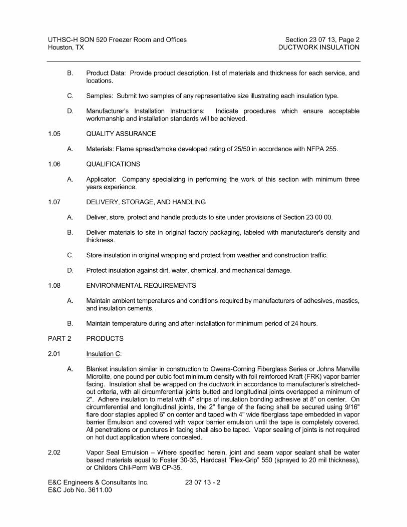
UTHSC-H SON 520 Freezer Room and Offices Section 23 07 13, Page 2Houston, TX DUCTWORK INSULATION
E&C Engineers & Consultants Inc. 23 07 13 - 2 E&C Job No. 3611.00
B. Product Data: Provide product description, list of materials and thickness for each service, and locations.
C. Samples: Submit two samples of any representative size illustrating each insulation type.
D. Manufacturer's Installation Instructions: Indicate procedures which ensure acceptable workmanship and installation standards will be achieved.
1.05 QUALITY ASSURANCE
A. Materials: Flame spread/smoke developed rating of 25/50 in accordance with NFPA 255.
1.06 QUALIFICATIONS
A. Applicator: Company specializing in performing the work of this section with minimum three years experience.
1.07 DELIVERY, STORAGE, AND HANDLING
A. Deliver, store, protect and handle products to site under provisions of Section 23 00 00.
B. Deliver materials to site in original factory packaging, labeled with manufacturer's density and thickness.
C. Store insulation in original wrapping and protect from weather and construction traffic.
D. Protect insulation against dirt, water, chemical, and mechanical damage.
1.08 ENVIRONMENTAL REQUIREMENTS
A. Maintain ambient temperatures and conditions required by manufacturers of adhesives, mastics, and insulation cements.
B. Maintain temperature during and after installation for minimum period of 24 hours.
PART 2 PRODUCTS
2.01 Insulation C:
A. Blanket insulation similar in construction to Owens-Corning Fiberglass Series or Johns Manville Microlite, one pound per cubic foot minimum density with foil reinforced Kraft (FRK) vapor barrier facing. Insulation shall be wrapped on the ductwork in accordance to manufacturer’s stretched-out criteria, with all circumferential joints butted and longitudinal joints overlapped a minimum of 2". Adhere insulation to metal with 4" strips of insulation bonding adhesive at 8" on center. On circumferential and longitudinal joints, the 2" flange of the facing shall be secured using 9/16" flare door staples applied 6" on center and taped with 4" wide fiberglass tape embedded in vapor barrier Emulsion and covered with vapor barrier emulsion until the tape is completely covered. All penetrations or punctures in facing shall also be taped. Vapor sealing of joints is not required on hot duct application where concealed.
2.02 Vapor Seal Emulsion – Where specified herein, joint and seam vapor sealant shall be water based materials equal to Foster 30-35, Hardcast “Flex-Grip” 550 (sprayed to 20 mil thickness), or Childers Chil-Perm WB CP-35.

UTHSC-H SON 520 Freezer Room and Offices Section 23 07 13, Page 3Houston, TX DUCTWORK INSULATION
E&C Engineers & Consultants Inc. 23 07 13 - 3 E&C Job No. 3611.00
2.03 All ductwork in the building and in the crawl spaces except exhaust and return ducts shall be insulated externally unless specifically excluded. Only sound attenuated return ducting may be insulated internally, if specifically designated as such.
2.04 Where ducts are lined internally, (see Drawings for Scope) no exterior insulation will be required, except where specifically stated otherwise. Where internal and external insulation join, they shall lap at least 24 inches.
2.05 Low pressure supply duct taps to ceiling diffusers shall be externally insulated including top of ceiling diffuser.
2.06 Flexible round ducts are specified in Section 23 31 00 as factory insulated.
PART 3 EXECUTION
3.01 EXAMINATION
A. Verify that ductwork has been tested before applying insulation materials.
B. Verify that surfaces are clean, foreign material removed, and dry.
3.02 INSTALLATION
A. Install materials in accordance with manufacturer's instructions.
B. Insulated ductwork conveying air below ambient temperature:
1. Provide insulation with vapor barrier jackets.
2. Finish with tape and vapor barrier jacket.
3. Continue insulation through walls, sleeves, hangers, and other duct penetrations.
4. Insulate entire system including fittings, joints, flanges, fire dampers, flexible connections, and expansion joints.
C. Insulated ductwork conveying air above ambient temperature:
1. Provide with or without standard vapor barrier jacket.
2. Insulate fittings and joints. Where service access is required, bevel and seal ends of insulation.
D. Duct and Plenum Liner Application:
1. Adhere insulation with adhesive for 100 percent coverage.
2. Secure insulation with mechanical liner fasteners. Refer to SMACNA Standards for spacing.
3. Seal and smooth joints.

UTHSC-H SON 520 Freezer Room and Offices Section 23 07 13, Page 4Houston, TX DUCTWORK INSULATION
E&C Engineers & Consultants Inc. 23 07 13 - 4 E&C Job No. 3611.00
4. Seal liner surface penetrations with adhesive.
5. Duct dimensions indicated are net inside dimensions required for air flow. Increase duct size to allow for insulation thickness.
3.03 All piping, equipment, ductwork, all plenums including metal and masonry construction, fans, etc., shall be insulated as indicated on the Drawings, as specified herein, and as required for a complete system. In each case, the insulation shall be equal to that specified and materials applied and finished as described in these Specifications.
3.04 All insulation shall be applied by mechanics skilled in this particular work and regularly engaged in such occupation. All insulation shall be applied in strict accordance with these Specifications and with factory printed recommendations on items not herein mentioned. Unsightly, inadequate, or sloppy work will not be acceptable, and all such work shall be removed and replaced as many times as necessary to achieve an acceptable installation.
3.05 All insulation, jacket, adhesives, mastics, sealers, etc., utilized in the fabrication of these systems shall meet NFPA for fire resistant ratings (maximum of 25 flame spread and 50 smoke developed ratings) and shall be approved by the insulation manufacturer for guaranteed performances when incorporated into their insulation system, unless a specific product is specified for a specific application, and is stated as an exception to this requirement. Certificates to this effect shall be submitted along with Contractor's submittal data for this section of the Specifications. No material may be used that, when tested by the ASTM E84-89 test method, is found to melt, drip or delaminate to such a degree that the continuity of the flame front is destroyed, thereby resulting in an artificially low flame spread rating.
3.06 All surfaces to be insulated shall be clean and dry before applying the insulation. Where an insulation covering is applied, it shall lap the adjoining section of insulation by at least three inches (3"). Where insulation terminates, it shall be neatly beveled and finished. No insulation shall be applied until the pipe, duct, etc., have been pressure tested and found tight. Flexible connections on duct shall not be covered. All materials used shall be fire retardant or nonflammable..
3.07 Where vapor barriers are required, the vapor barrier shall be on the outside. Extreme care shall be taken that the vapor barrier is unbroken. Joints, etc., shall all be sealed. Where insulation with a vapor barrier terminates, it shall be sealed off with the vapor barrier being continuous to the surface being insulated. Ends shall not be left raw.
3.08 Extreme care shall be taken in covering high and medium pressure (high and medium pressure ductwork shall be all ductwork between the fan discharge and all mixing boxes) ductwork to insure the duct is not pierced with sheet metal screws or other fasteners. All high and medium pressure ducts in these specifications are classified as high velocity ductwork.
3.09 Where canvas finish is specified, use Arabol lagging adhesive to prevent mildew in securing canvas. Do not use wheat paste. In addition, cover all canvas insulation with a fire retardant coating.
3.10 For purpose of definition in this Specification: "concealed" areas are those areas which cannot be seen by the building occupants, and "exposed" areas are all areas which are exposed to view by the building occupants, including under counter and inside cabinet areas, plus all mechanical rooms.
3.11 The handling and installation of all insulation materials shall be performed in strict accordance with the manufacturer’s recommendations.

UTHSC-H SON 520 Freezer Room and Offices Section 23 07 13, Page 5Houston, TX DUCTWORK INSULATION
E&C Engineers & Consultants Inc. 23 07 13 - 5 E&C Job No. 3611.00
3.12 TOLERANCE
A. Substituted insulation materials shall provide thermal resistance within 10 percent at normal conditions, as materials indicated.
3.13 DUCT INSULATION SCHEDULE:
Duct Type Insulation Type
Low Pressure Supply Duct 2" Insulation C(including tops of diffusers)
END OF SECTION


UTHSC-H SON 520 Freezer Room and Offices Section 23 07 19, Page 1Houston, TX PIPING INSULATION
E&C Engineers & Consultants Inc. 23 07 19 - 1 E&C Job No. 3611.00
SECTION 23 07 19
PIPING INSULATION
PART 1 GENERAL
1.01 The following sections are to be included as if written herein:
A. 23 00 00 -- Basic Mechanical RequirementsB. 23 05 29 -- Sleeves, Flashings, Supports and AnchorsC. 23 05 53 -- Mechanical Identification
1.02 SECTION INCLUDES
A. Piping insulation.B. Jackets and accessories.
1.03 1.02. PRODUCTS FURNISHED BUT NOT INSTALLED UNDER THIS SECTION
A. Section 23 21 00 - Hydronic Piping: Placement of hangers and hanger inserts.
1.04 1.03. RELATED SECTIONS
A. Section 09 91 00 - Painting: Painting pipe and insulation jacket.B. Section 23 00 00 - General Mechanical Requirements.C. Section 23 05 53 - Mechanical Identification.
1.05 1.04. REFERENCES
A. ASTM B209 - Aluminum and Aluminum-Alloy Sheet and Plate.B. ASTM C177 - Steady-State Heat Flux Measurements and Thermal Transmission
Properties by Means of the Guarded- Hot-Plate Apparatus.C. ASTM C195 - Mineral Fiber Thermal Insulation Cement.D. ASTM C335 - Steady-State Heat Transfer Properties of Horizontal Pipe Insulation.E. ASTM C449 - Mineral Fiber Hydraulic-setting ThermalF. ASTM C518 - Steady-State Heat Flux Measurements and Thermal Transmission
Properties by Means of the Heat Flow Meter Apparatus.G. ASTM C533 - Calcium Silicate Block and Pipe Thermal Insulation.H. ASTM C534 - Preformed Flexible Elastomeric Cellular Thermal Insulation in Sheet and
Tubular Form.I. ASTM C547 - Mineral Fiber Preformed Pipe Insulation.J. ASTM C552 - Cellular Glass Block and Pipe Thermal Insulation.K. ASTM C578 - Preformed, Block Type Cellular Polystyrene Thermal Insulation.L. ASTM C585 - Inner and Outer Diameters of Rigid Thermal Insulation for Nominal Sizes
of Pipe and Tubing (NPS System).M. ASTM C591 - Rigid Preformed Cellular Urethane Thermal Insulation.N. ASTM C610 - Expanded Perlite Block and Pipe Thermal Insulation.O. ASTM C640 - Corkboard and Cork Pipe Thermal Insulation.P. ASTM C921 - Properties of Jacketing Materials for Thermal Insulation.Q. ASTM D1056 - Flexible Cellular Materials - Sponge or Expanded Rubber.R. ASTM D1667 - Flexible Cellular Materials - Vinyl Chloride Polymers and Copolymers
(Closed Cell Foam).S. ASTM D2842 - Water Absorption of Rigid Cellular Plastics.T. ASTM E84 - Surface Burning Characteristics of Building Materials.U. ASTM E96 - Water Vapor Transmission of Materials.

UTHSC-H SON 520 Freezer Room and Offices Section 23 07 19, Page 2Houston, TX PIPING INSULATION
E&C Engineers & Consultants Inc. 23 07 19 - 2 E&C Job No. 3611.00
V. NFPA 255 - Surface Burning Characteristics of Building Materials.W. UL 723 - Surface Burning Characteristics of Building Materials.
1.06 SUBMITTALS
A. Submit under provisions of Section 23 00 00.B. Product Data: Provide product description, list of materials ‘k’ value, ‘R’ value, mean
temperature rating, and thickness for each service, and locations.C. Samples: When requested, submit two samples of any representative size illustrating
each insulation type.D. Manufacturer’s Installation Instructions: Submit the manufacturer’s published installation
documents for installation details, support and anchor methods, sealing, installation procedures and installation environment. Indicate procedures which ensure acceptable workmanship and installation standards will be achieved.
1.07 QUALITY ASSURANCE
A. All insulation, jacket, adhesives, mastics, sealers, etc., utilized in the fabrication of these systems shall meet NFPA for fire resistant ratings (maximum of 25 flame spread and 50 smoke developed ratings) and shall be approved by the insulation manufacturer for guaranteed performances when incorporated into their insulation system, unless a specific product is specified for a specific application, and is stated as an exception to this requirement. Certificates to this effect shall be submitted along with Contractor’s submittal data for this section of the Specifications. No material may be used that, when tested by the ASTM E84-89 test method, is found to melt, drip or delaminate to such a degree that the continuity of the flame front is destroyed, thereby resulting in an artificially low flame spread rating.
B. All surfaces to be insulated shall be clean and dry before applying the insulation. All sections of molded pipe covering shall be firmly butted together without voids. A mastic filler is not acceptable to fill voids. Where an insulation covering is applied, it shall lap the adjoining section of insulation by at least three inches (3”) on end sections and the longitudinal tape shall be 4” on jackets. Where insulation terminates, it shall be neatly beveled and finished moisture proof. No insulation shall be applied until the pipe, duct, etc., have been pressure tested and found tight. Piping, flexible connections, flanges, valves, strainers, and unions shall be covered unless specifically noted otherwise. Flexible connections on duct shall not be covered. All materials used shall be fire retardant or nonflammable. Refer to Section 23 00 00.
C. No insulation material shall be installed in combination with or contiguous to other types of insulation in a manner which could adversely impact the performance of either insulation material.
D. All piping, equipment, ductwork, all plenums including metal and masonry construction, fans, etc., shall be insulated as indicated on the Drawings, as specified herein, and as required for a complete system. In each case, the insulation shall be equal to that specified and materials applied and finished as described in these Specifications.
E. The manufacturer’s representative for the insulation shall visit the site a minimum of 4 times to review the installation practices, confer with the installer and prepare a field observation report that notes variations from manufacturer’s recommendations or recommendations to improve the installations.
F. To be considered, alternate materials shall have equivalent thermal, permability, water absorption and moisture resistance of the specified materials.
1.08 QUALIFICATIONS
A. All insulation shall be applied by mechanics skilled in this particular work and regularly engaged in such occupation.

UTHSC-H SON 520 Freezer Room and Offices Section 23 07 19, Page 3Houston, TX PIPING INSULATION
E&C Engineers & Consultants Inc. 23 07 19 - 3 E&C Job No. 3611.00
B. All insulation shall be applied in strict accordance with these Specifications and with factory printed recommendations on items not herein mentioned. Unsightly, inadequate, or sloppy work and torn vapor jackets will not be acceptable and all such work shall be removed and replaced as many times as necessary to achieve an acceptable installation. The company performing the work of this section shall have a minimum of three years experience specializing in the trade.
1.09 DELIVERY, STORAGE, AND HANDLING
A. Deliver, store, protect, and handle products to site under provisions of Section 23 00 00.B. Deliver materials to site in original factory packaging, labeled with manufacturer’s
identification, including product thermal ratings and thickness.C. Store insulation in original wrapping and protect from weather and construction traffic.
Protect insulation against dirt, water, chemical, and mechanical damage.
1.10 ENVIRONMENTAL REQUIREMENTS
A. Maintain ambient temperatures and conditions required by manufacturers of adhesives, mastics, and insulation cements.
B. Maintain temperature during and after installation for minimum period of 24 hours.C. All insulation materials to be asbestos free.
PART 2 PRODUCTS
2.01 DOMESTIC HOT AND COLD WATER
A. All domestic hot and cold water lines in buildings, including valves, strainers, unions, flanges, etc., except where specifically noted to the contrary, shall be insulated.
B. All domestic cold water lines shall be insulated as scheduled with preformed fiberglass insulation with a factory applied All Service Jacket, vapor sealing all joints, and factory performed fittings with vapor seal, or a flexible, “25-50” rated, closed cell elastomeric thermal insulation such as “Self Seal Armaflex 2000”. Elastomeric products shall be supplied in a pre-slit tubular form with a pressure sensitive adhesive system for closure and vapor sealing of the longitudinal joint. All elastomeric insulating products shall be guaranteed not to react with copper piping. Valves shall be insulated with mitered pipe covering with voids filled with glass fiber blanket insulation. Valves and fittings shall be vapor sealed with a water base asphaltic emulsion. Fittings on concealed insulation shall be built up to the thickness of adjacent insulation with glass fiber fitting wrap and shall be finished with Glasfab tape embedded in vapor barrier emulsion. Exposed fitting insulation shall be built up to same thickness as adjoining pipe insulation with one coat cement and after drying shall be finished with a white vapor seal and canvas jacket secured with “Arabol” adhesive and be suitable for painting. Seams in jacket shall be placed in the least noticeable locations. Where seams, joint or fittings are rough they shall be covered with an application of insulating cement troweled on smoothly before the canvas is applied with Arabol adhesive. The canvas must be free of wrinkles and have a smooth, neat appearance.
C. All domestic hot water piping systems shall be insulated as specified above for cold water except the vapor barrier may be deleted and the lap and butt joints secured with staples and a field applied adhesive (self sealing lap and butt joints alone are not acceptable). The insulation thickness shall be as scheduled. Where service temperature exceeds 250F, insulation shall contain high temp binders.

UTHSC-H SON 520 Freezer Room and Offices Section 23 07 19, Page 4Houston, TX PIPING INSULATION
E&C Engineers & Consultants Inc. 23 07 19 - 4 E&C Job No. 3611.00
D. The only domestic hot and cold water piping that will not require insulation are the exposed runouts under non-handicap plumbing fixtures. Where pipe chases are tight, adequate provision shall be made at the rough in stage utilizing offset fittings or other means (except springing the pipe) to insure that insulation can be applied throughout the length of the pipe.
2.01 PROTECTIVE JACKETING:
A. Provide protective jacketing as described elsewhere.B. Jacketing and fitting covers shall be .016 aluminum smooth as manufactured by
Premetco or Childers. The jacket shall be pre-cut, pre-rolled, and lapped a minimum of two inches (2”) In all directions to shed water. The metal shall be secured at each joint with a minimum of one each (1 ea.) ¾” wide .020 aluminum or stainless steel band and seal. The metal jacketing and fitting covers shall be fabricated of 0.016” aluminum or stainless steel with a smooth finish.
PART 3 EXECUTION
3.01 EXAMINATION
A. Verify that piping has been tested before applying insulation materials.B. Verify that surfaces are clean, foreign material removed, and dry.
3.02 INSTALLATION
A. Install materials in accordance with manufacturer’s instructions in the absence of more restrictive requirements or specific instruction herein.
B. For domestic cold water pipe, seal the ends of fiberglass insulation and provide vapor dams at each end location or every 18’, which ever is shorter. Provide vapor dams between pipe and insulation on elastomeric insulation at each section end location or every 20’ which ever is shorter.
C. On exposed piping, locate insulation and cover seams in least visible locations, but not higher than at the side of the pipe at the “90°” position, with the seam lapped such that the lap is directed down.
D. Insulated dual temperature pipes or cold pipes conveying fluids below ambient temperature: Vapor barriers are required. The vapor barrier shall be on the outside. Extreme care shall be taken that the vapor barrier is unbroken. Joints, etc., shall be sealed. Where insulation with a vapor barrier terminates, it shall be sealed off with the vapor barrier being continuous to the surface being insulated. Ends shall not be left raw.1. Provide vapor barrier jackets, factory applied or field applied. Vapor barrier
jacket shall be equal to a Venture Wrap 3.4 mil, “0” perm, cleanable surface vapor jacket with 4” overlap tape strip.
2. Insulate fittings, joints, and valves with molded insulation of like material and thickness as adjacent pipe.
3. Finish with glass cloth and vapor barrier adhesive.E. Continue insulation through walls, sleeves, pipe hangers, and other pipe penetrations.F. For insulated pipes conveying fluids above ambient temperature:
1. Provide standard jackets, with or without vapor barrier, factory applied or field applied.
2. Insulate fittings, joints, and valves with insulation of like material and thickness as adjoining pipe.
G. If PVC fitting covers are used they shall have 25/50 rating.H. For hot piping conveying fluids 140F or less, do not insulate flanges and unions at
equipment, but bevel and seal ends of insulation.
3.03 INSERTS, SUPPORTS AND SHIELDS:

UTHSC-H SON 520 Freezer Room and Offices Section 23 07 19, Page 5Houston, TX PIPING INSULATION
E&C Engineers & Consultants Inc. 23 07 19 - 5 E&C Job No. 3611.00
A. Application: Piping 2 inches diameter or larger for all systems except direct buried.B. Shields: Install between pipe hangers or pipe hanger rolls and inserts. Hangers shall be
on the outside of the insulation and shall not be in contact with the pipe. Curved metal shields shall be used between the hangers or support points and the bottom of the insulated pipe for Insulated pipes 2” and larger. Curved metal shields shall be designed to limit the bearing stress on the insulation to 35 psi, shall be curved to fit up to mid-perimeter of the insulated pipe and to prevent sharp corners from contacting the jacket. Shields shall be made of galvanized iron, or black iron painted on both sides with two coats of aluminum paint. Required metal shield sizes are as follows:
LengthsNominal IPS Metal Thickness of Shieldup thru 2” 14 gauge 12”thru 6” 12 gauge 16”and above 10 gauge 20”
C. Insert Location: Between support shield and piping and under the finish jacket.D. Insert Configuration: Minimum 2” inches longer than length of shield, of same thickness
and contour as adjoining insulation; may be factory fabricated.E. Insert Material: Heavy density insulating material suitable for the planned temperature
range, and the weight of the pipe.F. The shields at support points shall be secured with ½” x 0.016” stainless steel bands and
seals.G. Finish insulation at supports, protrusions, and interruptions.H. The application of the protective shields at rack and guide points in tunnels and in central
chilling stations shall be as detailed on the accompanying Drawings.I. In lieu of the above the following system of support may be used:
1. At the pipe support positions, the insulation and vapor barrier shall be continuous and shall not be punctured by the support. The insulation at the support shall be the full circumference of 5lbs/ft3 Phenolic Foam material to withstand the bearing loads transmitted from the pipe to the support, it shall extend for at least 1" on either side of the support to allow sealing of the joints with the pipe insulation jacket.
2. The load bearing insulation at the support shall be capable of withstanding the maximum static compressive loads generated by pipe supported at the centers shown in Table 1.
Variations: Pipe loads greater than those generated at the support centers shown in Table 1 shall be referred to the manufacturer to establish the length and density of the insulated support block. The support centers are based on the weight of Sch 80 pipe filled with water and covered with 1" thickness of 2.2 lbs/ft3 standard insulation including FSK/ASJ vapor barrier.

UTHSC-H SON 520 Freezer Room and Offices Section 23 07 19, Page 6Houston, TX PIPING INSULATION
E&C Engineers & Consultants Inc. 23 07 19 - 6 E&C Job No. 3611.00
J. Table 1 K Block Support CentersNominal Pipe Size 3/4 1 1
1/42 2
1/23 4 6 8 10 12 14 16 18 20 24
Max support centers (feet)
Sch 80 pipe filled with water covered with 1" of Standard Insulation
6.5 6.5 6.5 10 10 10 10 10 14 14 14 20 20 20 20 20
Metal Saddle Gauge(Galvanized Steel)
22 22 22 20 20 20 16 14 14 14 14 14 114 14 14 14
Length of K Block(inches)
6 6 6 6 6 6 6 9 9 9 9 9 9 12 12 12
1. The Insulation at supports shall be a equal to Kooltherm K Block. K Blocks shall be faced with factory applied vapor barrier and fitted with a galvanized steel 1800 saddle bonded to the bottom section of the K Block, for all pipe sizes 1 1/2" and larger.
2. The vapor barrier shall be completed by the use of a vapor barrier jacket 4” overlap and factory applied self-seal lap tape and sealed with vapor barrier adhesive.
3. At all support positions, other than those where the insulated pipe support block is surrounded by a clip or saddle in direct contact with the block, a block designed to accept the loads generated by the pipe shall be presented to the engineer for approval. e.g. Of the type Kooltherm Insulation products K Block. Ref:- Kooltherm sketch 106/2c for use with Roller or flat beam support.
4. In all cases where roller supports are used the length of the insulation and the wearing plate where fitted shall extend beyond the limits of the pipe movement.
K. Where canvas finish is specified, use Arabol lagging adhesive to prevent mildew in securing canvas. Do not use wheat paste. In addition, cover all canvas insulation with a fire retardant coating.
L. For purpose of definition in this Specification: “concealed” areas are those areas which cannot be seen by the building occupants, and “exposed” areas are all areas which are exposed to view by the building occupants, including under counter and inside cabinet areas, plus all mechanical rooms.
M. Self Sealing Lap and butt joints will not be acceptable as the only seal on piping insulation joints. Self Sealing Lap and butt joints may be utilized only if the joints are additionally secured with field applied vapor barrier adhesive (on piping Systems requiring vapor barriers) or staples and field applied adhesive (on piping system which do not require a vapor barrier jacket). Mechanical fasteners shall be used whenever possible to assure permanent installation.
N. Insulation minimum thickness shall be as scheduled; however, additional thickness shall be provided to prevent condensation on the cold surfaces and to provide a maximum exterior insulation surface of 140F on the hot surfaces.
O. Special Protection: All insulated piping in the mechanical rooms within 8’-0” of the floor shall be encased in a protective jacket, and where applicable, finish at top with nickel-plated brass flange plate with set screws or end joint sealing butt strips.
P. Interior or conditioned areas are those where ambient conditions are typically below 76°F and humidities are below 60% RH. All other areas shall be considered exterior or exposed to outside conditions.
Q. Fitting insulation shall be applied in same manner as pipe application. Protruding metal parts (such as valve stems) shall be completely sealed off. Fitting cover jacketing shall be equal to Gasco, Pabco or RPR Metals prefabricated fitting covers of 0.016” paper coated aluminum, secured as recommended by the manufacturer.
R. No pipe supporting device (other than guides or anchors attached directly to the pipe) shall penetrate the insulation.

UTHSC-H SON 520 Freezer Room and Offices Section 23 07 19, Page 7Houston, TX PIPING INSULATION
E&C Engineers & Consultants Inc. 23 07 19 - 7 E&C Job No. 3611.00
3.04 INSULATION TABLE:
Insulation ‘R’ Value Schedule (R = thickness / k)
Oper ‘k’ @ Min. R value for each Pipe SizeTemp Mean 1” 1-1/4” 2-1/2” 5” & 8” &
Service F Temp F & less to 2” to 4” 6” over
Hot(1) 350+ .33 @ 250 7.5 7.5 10.0 12.0 13.0Hot(2) 251-350 .30 @ 200 6.5 8.5 8.5 11.5 12.5Hot(3) 201-250 .29 @ 150 5.2 5.2 6.9 6.9 12.1Hot(4) 141-200 .27 @ 125 5.6 5.6 5.6 5.6 5.6Hot(5) 105-140 .26 @ 100 3.8 3.8 5.8 5.8 5.8
Cold(6) 40-55 .25 @ 75 2.0 3.0 4.0 4.0 4.0Cold(7) below 40 .25 @ 75 4.0 6.0 6.0 6.0 6.0
(1) HTHW; Steam @ over 120#(2) HTHW; Steam @ 16# to120#; med & hp condensate; water and fire line freeze protection(3) HTHW; Steam @ 0# to 15#; LP Condensate(4) HW(5) HW(6) Ch. Wtr; Dom. cold wtr; Storm; Cold condensate(7) Ch. Wtr; Brine; Refrig lines
Minimum ‘R’ does not consider water vapor transmission and condensation. Additional insulation and/or vapor retarders may be required to limit water vapor transmission and condensation under extreme conditions.
A minus 15 percent tolerance, on the insulation performance listed shall be permitted for manufacturers' standard insulation systems
No chilled or heating water insulation shall be less than 2” thickness. No chilled water pipe insulation in unconditioned space shall be less than three inch thickness.
END OF SECTION


UTHSC-H SON 520 Freezer Room and Offices Section 23 09 23, Page 1Houston, TX DIRECT DIGITAL CONTROL SYSTEMS
E&C Engineers & Consultants Inc. 23 09 23 - 1 E&C Job No. 3611.00
SECTION 23 09 23
DIRECT DIGITAL CONTROL SYSTEMSBACKBONE SYSTEMS HAVE BEEN INSTALLED IN THE SHELL & CORE
INFORMATION ON PREVIOUSLY INSTALLED EQUIPMENT IS FOR INFORMATION ONLY.ADDITIONAL EQUIPMENT AS NOTED WILL BE REQUIREDAS NOTED ON THE DRAWINGS.
PART 1 GENERAL
1.01 THE FOLLOWING SECTIONS ARE TO BE INCLUDED AS IF WRITTEN HEREIN:
A Section 23 00 00 – Basic Mechanical RequirementsB Section 23 05 29 – Sleeves, Flashings, Supports and AnchorsC Section 23 05 53 – Mechanical Identification
1.02 SECTION INCLUDES
A Control equipment.B Software.
1.03 PRODUCTS FURNISHED BUT NOT INSTALLED UNDER THIS SECTION
A Section 23 33 00 - Ductwork Accessories: Installation of automatic dampers, smoke detectors. Connection of damper end switches.
1.04 RELATED SECTIONS
A Section 26 05 00 - Equipment Wiring Systems.
1.05 REFERENCES
A ASHRAE 85 - Automatic Control Terminology for Heating, Ventilating, Air Conditioning.B ASME MC85.1 - Terminology for Automatic Control.C NEMA EMC1 - Energy Management Systems Definitions.
1.06 DEFINITIONS
A Ensure terminology used in submittals conforms to ASHRAE 85.
1.07 SYSTEM DESCRIPTION
A The system is an existing JCI system. The extent of this work shall be to add new wireless and relocate temperature sensors as shown on the drawings only.
B Automatic temperature control field monitoring and control system using field programmable micro-processor based units with communications to the existing Metasys Campus Building Management System.
C Central and remote hardware, software, and interconnecting wire and conduit.D Terminal unit controls for variable air volume terminals, radiation, reheat coils, unit
heaters, fan coils, pneumatic or electric unless indicated otherwise.E The DDC systems shall be installed by JCI under a direct contract with the General
Contractor. JCI shall provide “open-book” pricing to the General Contractor and UTHSC-H per the existing UTHSC-H/JCI agreement.
F All sensors that are installed in insulated pipe or ductwork shall be installed with standoffs to allow proper insulation of all materials and continuation of vapor barriers.

UTHSC-H SON 520 Freezer Room and Offices Section 23 09 23, Page 2Houston, TX DIRECT DIGITAL CONTROL SYSTEMS
E&C Engineers & Consultants Inc. 23 09 23 - 2 E&C Job No. 3611.00
1.08 SUBMITTALS
A Submit under provisions of Section 01 33 00.B Shop Drawings:
1. Trunk cable schematic showing programmable control unit locations, and trunk data conductors.
2. List of connected data points, including connected control unit and input device.3. System graphics indicating monitored systems, data (connected and calculated)
point addresses, and operator notations.4. System configuration with peripheral devices, batteries, power supplies,
diagrams, modems, and interconnections.5. Descriptive data and sequence of operation of operating, user, and application
software.6. Provide one additional submittal above that which is asked for in Division 1 to be
distributed by UTHSC-H to the IT department for verification.C Product Data: Provide data for each system component and software module.D Manufacturer's Installation Instructions: Include for all manufactured components.
1.09 PROJECT RECORD DOCUMENTS
A Submit under provisions of Section 01 77 00.B Accurately record actual location of control components, including panels, thermostats,
and sensors.C Revise shop drawings to reflect actual installation and operating sequences.D Include data specified in "Submittals" in final "Record Documents" form.
1.10 OPERATION AND MAINTENANCE DATA
A Submit under provisions of Section 01 77 00.B Include interconnection wiring diagrams complete field installed system with identified
and numbered, system components and devices.C Include keyboard illustrations and step-by-step procedures indexed for each operator
function.D Include graphics of the controlled system as they appear on the system graphics with
variable, adjustable and fixed pints with showing identified and numbered systems, system components and devices.
E Include inspection period, cleaning methods, cleaning materials recommended, and calibration tolerances.
1.11 QUALIFICATIONS
A Manufacturer: JCI controls.B Installer: JCI controlsC Design system software under direct supervision of a Professional Engineer experienced
in design of this work and licensed in the State of Texas.
1.12 PRE-INSTALLATION CONFERENCE
A Convene a conference one week prior to commencing work of this Section, under provisions of Section 01200.
B Require attendance of parties directly affecting the work of this Section.
1.13 COORDINATION
A Coordinate work under provisions of Section 00 10 05.

UTHSC-H SON 520 Freezer Room and Offices Section 23 09 23, Page 3Houston, TX DIRECT DIGITAL CONTROL SYSTEMS
E&C Engineers & Consultants Inc. 23 09 23 - 3 E&C Job No. 3611.00
B Ensure installation of components is complementary to installation of similar components in other systems.
C Coordinate installation of system components with installation of mechanical systems equipment such as air handling units and air terminal units.
D Coordinate the startup and control sequence verification with the test and balance agent.E Ensure system is completed and commissioned.
1.14 WARRANTY
A Provide five year warranty under provisions of Section 01 78 36.B Warranty: Include coverage for field programmable micro-processor based units.
1.15 PROTECTION OF SOFTWARE RIGHTS
A Prior to delivery of software, the Owner and the party providing the software will enter into a software license agreement with provisions for the following:1. Limiting use of software to equipment provided under these specifications.2. Limiting copying.3. Preserving confidentiality.4. Prohibiting transfer to a third party.
PART 2 PRODUCTS
2.01 MANUFACTURERS OF CONTROLS
A JCI
2.02 GENERAL DESCRIPTION
A The Building Management System (BMS) shall use an open architecture and fully support a multi-vendor environment. To accomplish this effectively, the BMS shall support open communication protocol standards and integrate a wide variety of third-party devices and applications. The system shall be designed for use on the Internet, or intranets using off the shelf, industry standard technology compatible with other owner provided networks. Prior to submittal update equipment to the latest technology and coordinate with the Engineer.
B The Building Management System shall consist of the following:1. Standalone Network Automation Engine(s)2. Field Equipment Controller(s) 3. Input/Output Module(s)4. Local Display Device(s)5. Portable Operator's Terminal(s)6. Distributed User Interface(s)7. Network processing, data storage and communications equipment 8. Other components required for a complete and working BMS
C The system shall be modular in nature, and shall permit expansion of both capacity and functionality through the addition of sensors, actuators, controllers and operator devices, while re-using existing controls equipment.
D System architectural design shall eliminate dependence upon any single device for alarm reporting and control execution. 1. The failure of any single component or network connection shall not interrupt the
execution of control strategies at other operational devices.2. The System shall maintain all settings and overrides through a system reboot.3. System architectural design shall eliminate dependence upon any single device
for alarm reporting and control execution.

UTHSC-H SON 520 Freezer Room and Offices Section 23 09 23, Page 4Houston, TX DIRECT DIGITAL CONTROL SYSTEMS
E&C Engineers & Consultants Inc. 23 09 23 - 4 E&C Job No. 3611.00
E Conduit and boxes shall be installed and supported per 23 05 29. Controls conduit shall be ¾” EMT that is blue in color. The boxes shall be type 1900 and where the mixing box is located inside of the office area, the conduit shall be stubbed on from the junction box into the office space as close to the box as possible above the ceiling.
2.03 FIELD DEVICES
A Thermostats1. Electric room thermostats of the heavy-duty type shall be provided for unit
heaters, cabinet unit heaters, and ventilation fans, where required. All these items shall be provided with concealed adjustment. Finish of covers for all room-type instruments shall match and, unless otherwise indicated or specified, covers shall be manufacturer’s standard finish.
2. Actuation / Control Type3. Primary Equipment
a. Controls shall be provided by equipment manufacturer as specified herein.
b. All damper and valve actuation shall be electric.4. Air Handling Equipment
a. All air handers shall be controlled with a HVAC-DDC Controllerb. All damper and valve actuation shall be electric.
PART 3 EXECUTION
Not Used
END OF SECTION

UTHSC-H SON 520 Freezer Room and Offices Section 23 20 00.A, Page 1Houston, TX PIPING VALVES AND FITTINGS
E&C Engineers & Consultants Inc. 23 20 00.A - 1 E&C Job No. 3611.00
SECTION 23 20 00.A
PIPING, VALVES AND FITTINGS
PART 1 GENERAL
1.01 The following sections are to be included as if written herein:
A. Section 23 00 00 – Basic Mechanical RequirementsB. Section 23 05 29 – Sleeves, Flashings, Supports and AnchorsC. Section 23 05 53 – Mechanical Identification
1.02 SECTION INCLUDES
A. Pipe and pipe fittings.B. Valves.
1.03 RELATED SECTIONS
A. Section 23 00 00 - Basic Mechanical Requirements.B. Section 23 05 29 - Sleeves, Supports and Anchors.C. Section 23 05 53 - Mechanical Identification.D. Section 23 05 48 - Vibration Isolation.E. Section 23 07 19 - Piping Insulation.
1.04 REFERENCES
A. AGA - American Gas Association.B. ANSI B31.1 - Power Piping.C. ANSI B31.9 - Building Service Piping.D. ASME Sec. 9 - Welding and Brazing Qualifications.E. ASME B16.1 - Cast Iron Pipe Flanges and Flanged Fittings Class 25, 125, 250 and 800.F. ASME B16.3 - Malleable Iron Threaded Fittings.G. ASME B16.4 - Cast Iron Threaded Fittings Class 125 and 250.H. ASME B16.18 - Cast Bronze Solder-Joint Pressure fittings.I. ASME B16.22 - Wrought Copper and Bronze Solder-Joint Pressure FittingsJ. ASME B16.23 - Cast Copper Alloy Solder-Joint Drainage Fittings - DWV.K. ASME B16.26 - Cast Bronze Fittings for Flared Copper Tubes.L. ASME B16.29 - Wrought Copper and Wrought Copper Alloy Solder Joint Drainage
Fittings - DWV.M. ASME B16.32 - Cast Copper Alloy Solder-Joint Fittings for Solvent Drainage Systems.N. ASTM A47 - Ferric Malleable Iron Castings.O. ASTM A135 - Pipe, Steel, Black and Hot-Dipped Zinc Coated, Welded and Seamless.P. ASTM A74 - Cast Iron Soil Pipe and Fittings.Q. ASTM A234 - Pipe Fittings of Wrought Carbon Steel and Alloy Steel for Moderate and
Elevated Temperatures.R. ASTM B32 - Solder Metal.S. ASTM B42 - Seamless Copper Pipe.T. ASTM B43 - Seamless Red Brass Pipe.U. ASTM B75 - Seamless Copper Tube.V. ASTM B88 - Seamless Copper Water Tube.W. ASTM B251 - Wrought Seamless Copper and Copper-Alloy Tube.X. ASTM B302 - Threadless Copper Pipe (TP).Y. ASTM B306 - Copper Drainage Tube (DWV).Z. ASTM C14 - Concrete Sewer, Storm Drain, and Culvert Pipe.AA. ASTM C425 - Compression Joints for Vitrified Clay Pipe and Fittings.
UTHSC-H SON 520 Freezer Room and Offices Section 23 20 00.A, Page 2Houston, TX PIPING VALVES AND FITTINGS
E&C Engineers & Consultants Inc. 23 20 00.A - 2 E&C Job No. 3611.00
BB. ASTM C443 - Joints for Circular Concrete Sewer and Culvert Pipe, Using Rubber Gaskets.
CC. ASTM C564 - Rubber Gaskets for Cast Iron Soil Pipe and Fittings.DD. ASTM C700 - Vitrified Clay Pipe, Extra Strength, Standard Strength, and Perforated.EE. ASTM D1785 - Poly (Vinyl Chloride) (PVC) Plastic Pipe, Schedules 40, 80, and 120.FF. ASTM D2235 - Solvent Cement for Acrylonitrile - Butadiene - Styrene (ABS) Plastic Pipe
and Fittings.GG. ASTM D2241 - Poly (Vinyl Chloride) (PVC) Plastic Pipe (SDR-PR).HH. ASTM D2466 - Poly (Vinyl Chloride) (PVC) Plastic Pipe Fittings, Schedule 40.II. ASTM D2564 - Solvent Cements for Poly (Vinyl Chloride) (PVC) Plastic Pipe and Fittings.JJ. ASTM D2680 - Acrylonitrile-Butadiene-Styrene (ABS) Composite-Sewer Piping.KK. ASTM D2683 - Socket-Type Polyethylene Fillings for Outside Diameter-Controlled
Polyethylene Pipe.LL. ASTM D2729 - Poly (Vinyl Chloride) (PVC) Sewer Pipe and Fittings.MM. ASTM D2751 - Acrylonitrile-Butadiene-Styrene (ABS) Sewer Pipe and Fittings.NN. ASTM D2846 - Chlorinated Polyvinyl Chloride (CPVC) Pipe, Fittings, Solvent Cements
and Adhesives for Potable Hot Water Systems.OO. ASTM D2855 - Making Solvent-Cemented Joints with Poly (Vinyl Chloride) (PVC) Pipe
and Fittings.PP. ASTM D3033 - Type PSP Poly (Vinyl Chloride) (PVC) Sewer Pipe and Fittings.QQ. ASTM D3034 - Type PSM Poly (Vinyl Chloride) (PVC) Sewer Pipe and Fittings.RR. ASTM D3309 - Polybutylene (PB) Plastic Hot Water Distribution System.SS. ASTM F477 - Elastomeric Seals (Gaskets) for Joining Plastic Pipe.TT. ASTM F493 - Solvent Cements for Chlorinated Poly (Vinyl Chloride) (CPVC) Plastic Pipe
and Fittings.UU. ASTM F845 - Plastic Insert Fittings for Polybutylene (PB) Pipe.VV. AWS A5.8 - Brazing Filler Metal. BA. AWWA C105 - Polyethylene Encasement for
Ductile Iron Piping for Water and Other Liquids.WW. AWWA C110 - Ductile - Iron and Gray - Iron Fittings 3 in. through 48 in., for Water and
Other Liquids.XX. AWWA C111- Rubber-Gasket Joints for Ductile Iron and Gray-Iron Pressure Pipe and
Fittings.YY. AWWA C151 - Ductile-Iron Pipe, Centrifugally Cast in Metal Molds or Sand-Lined Molds,
for Water or Other Liquids.ZZ. AWWA C651 - Disinfecting Water Mains.AAA. CISPI 301 - Cast Iron Soil Pipe and Fittings for Hubless Cast Iron Sanitary Systems.BBB. CISPI 310 - Joints for Hubless Cast Iron Sanitary Systems.CCC. CAN-3 B281 - Aluminum Drain, Waste, and Vent Pipe and Components.DDD. NCPWB - Procedure Specifications for Pipe Welding.EEE. TDH - Texas Department of Health, Water System Regulations
1.05 SUBMITTALS
A. Submit under provisions of Section 23 00 00.B. Product Data: Provide data on pipe materials, pipe fittings, valves, and accessories.
Provide manufacturers catalog information. Indicate valve data and ratings.
1.06 PROJECT RECORD DOCUMENTS
A. Submit under provisions of Section 23 00 00.B. Record actual locations of valves, etc. and prepare valve charts.
1.07 OPERATION AND MAINTENANCE DATA
A. Submit under provisions of Section 23 00 00.

UTHSC-H SON 520 Freezer Room and Offices Section 23 20 00.A, Page 3Houston, TX PIPING VALVES AND FITTINGS
E&C Engineers & Consultants Inc. 23 20 00.A - 3 E&C Job No. 3611.00
B. Maintenance Data: Include installation instructions, spare parts lists, exploded assembly views.
1.08 QUALITY ASSURANCE
A. Valves: Manufacturer's name and pressure rating marked on valve body.B. Welding Materials and Procedures: Conform to ASME Code and applicable state labor
regulations.C. Welders Certification: In accordance with ASME Sec. 9. Submit welder’s certifications
prior to any shop or field fabrication. Welder’s certifications shall be current within six months of submission.
D. Maintain one copy of each document on site.
1.09 QUALIFICATIONS
A. Manufacturer: Company specializing in manufacturing the Products specified in this section with minimum three years documented experience.
B. Installer: Company specializing in performing the work of this section with minimum of three years documented experience.
1.10 DELIVERY, STORAGE, AND HANDLING
A. Deliver, store, protect and handle products to site under provisions of Section 23 00 00.B. Accept valves on site in shipping containers with labeling in place. Inspect for damage.C. Provide temporary protective coating on cast iron and steel valves.D. Provide temporary end caps and closures on piping and fittings. Maintain in place until
installation.E. Protect piping systems from entry of foreign materials by temporary covers, completing
sections of the work, and isolating parts of completed system.
1.11 ENVIRONMENTAL REQUIREMENTS
A. Do not install underground piping when bedding are wet or frozen.
1.12 EXTRA MATERIALS
A. Furnish under provisions of Section 23 00 00.B. Provide two repacking kits for each size valve.
PART 2 PRODUCTS
2.01 STEEL PIPING:
A. Scope: This section applies to all piping systems providing for welded piping, fittings, and other appurtenances. Specific systems requiring welded piping include, but are not limited to: chilled water, hot water, steam, steam condensate, and fire protection systems.
B. Pipe: Unless otherwise indicated, chiller and boiler plants piping shall be Schedule 40, and underground and building piping shall be Standard weight, Grade A or B, seamless black steel pipe conforming in all details to Standard ASTM Designation A135, A106, and A53, latest revisions. Steam condensate shall be Schedule 80. All piping shall be domestic made.
C. Fittings:1. All weld fittings shall be domestic made wrought carbon steel butt-welding fittings
conforming to ASTM A234 and ASME/ANSI B16.9, latest edition, as made by
UTHSC-H SON 520 Freezer Room and Offices Section 23 20 00.A, Page 4Houston, TX PIPING VALVES AND FITTINGS
E&C Engineers & Consultants Inc. 23 20 00.A - 4 E&C Job No. 3611.00
Weld Bend, Tube Turn, Hackney, or Ladish Company. Attach to only pipe with a hole for the entire length. Each fitting shall be stamped as specified by ASME/ANSI B16.9 and, in addition, shall have the laboratory control number metal stenciled on each fitting for ready reference as to physical properties required for any fittings selected at random. Fittings which have been machined, remarked, printed or otherwise produced domestically from non-domestic forgings or materials will not be acceptable. Each fitting to be marked in accordance with MSS SP-25. Markings shall be placed on the fittings at the farthest point from the edge to be welded to prevent disfiguring from the welding process. Submittal data for these fittings shall include a letter signed by an official of the manufacturing firm certifying compliance with these specifications.
2. All screwed pattern fittings specifically called for shall be Class 150 malleable iron fittings of Grinnell Company, Crane Company or Walworth Company manufacture (300 lb. for unions).
D. FABRICATION:1. Welded piping and fittings in chiller and boiler plants and distribution systems
shall be fabricated in accordance with ASME/ANSI the latest editions of Standard B31.1 Downstream of building PRV station Standard B31.3 shall be used for Steam and Condensate systems. Standard B31.9 –Building Services Piping may be used within buildings for non-steam and condensate systems. Machine beveling in shop is preferred. Field beveling may be done by flame cutting to recognized standards.
2. Ensure complete penetration of deposited metal with base metal. Contractor shall provide filler metal suitable for use with base metal. Contractor shall keep inside of fittings free from globules of weld metal. All welded pipe joints shall be made by the fusion welding process, employing a metallic arc or gas welding process. All pipe shall have the ends beveled 37-1/2 degrees and all joints shall be aligned true before welding. Except as specified otherwise, all changes in direction, intersection of lines, reduction in pipe size and the like shall be made with factory-fabricated welding fittings. Mitering of pipe to form elbows, notching of straight runs to form tees, or any similar construction will not be permitted.
3. Align piping and equipment so that no part is offset more than 1/16 inch. Set all fittings and joints square and true, and preserve alignment during welding operation. Use of alignment rods inside pipe is prohibited.
4. Do not permit any weld to project within the pipe so as to restrict it. Tack welds, if used, must be of the same material and made by the same procedure as the completed weld. Otherwise, remove tack welds during welding operation.
5. Do not split, bend, flatten or otherwise damage piping before, during or after installation.
6. Remove dirt, scale and other foreign matter from the inside of piping, by swabbing or flushing, prior to the connection of other piping sections, fittings, valves or equipment.
7. In no cases shall Schedule 40 pipe be welded with less than three passes including one stringer/root, one filler and one lacer. Schedule 80 pipe shall be welded with not less than four passes including one stringer/root, two filler and one lacer. In all cases, however, the weld must be filled before the cap weld is added.
8. 8. Procedure of Assembling Screw Pipe Fittings: All screw joints shall be made with taper threads, properly cut. Joints shall be made tight with Teflon applied to the pipe threads only and not to fittings. When threads are cut on pipes, the ends shall be carefully reamed to remove any burrs. Before installing pipe that has been cut and threaded, the lengths of pipe shall be upended and hammered to remove all shavings and foreign material.
E. WELD TESTING:1. All welds are subject to inspection, visual and/or X-ray, for compliance with
specifications. The owner will, at the owners option, provide employees or

UTHSC-H SON 520 Freezer Room and Offices Section 23 20 00.A, Page 5Houston, TX PIPING VALVES AND FITTINGS
E&C Engineers & Consultants Inc. 23 20 00.A - 5 E&C Job No. 3611.00
employ a testing laboratory for the purposes of performing said inspections and/or X-ray testing. Initial visual and X-ray inspections will be provided by the owner. The contractor shall be responsible for all labor, material and travel expenses involved in the reinspection and retesting of any welds found to be unacceptable. In addition, the contractor shall be responsible for the costs involved in any and all additional testing required or recommended by ASME/ANSI Standards B31.1, B31.9 and B31.3 due to the discovery of poor, unacceptable or rejected welds. For every failed x-ray, contractor shall be liable to provide five additional joint x-rays.
2. Welds lacking penetration, containing excessive porosity or cracks, or are found to be unacceptable for any reason, must be removed and replaced with an original quality weld as specified herein. All qualifying tests, welding and stress relieving procedures shall, moreover, be in accord with Standard Qualification for Welding Procedures, Welders and Welding Operators Code, current edition.
2.02 CAST IRON PIPING:
A. PIPE & FITTINGS:1. Service weight cast iron soil pipe conforming to ASTM Specification A-74 and
CISPI Standard 301, hub and spigot for pipe ten inch (10") and larger and hubless for eight inch (8") and smaller. Each piece of pipe and each fitting shall be coated at the factory with asphaltum or coal tar pitch and with the manufacturer's mark or name cast on it.
2. All joints in hub and spigot cast iron pipe shall be made water and gas tight with Tyseal neoprene gaskets. Lead and Oakum may be used only under special conditions, with prior written permission from the Resident Construction Manager. Joints in hubless cast iron soil pipe and fittings shall be made by the use of a neoprene sleeve and 24 gage, Type 304 Stainless Steel shield made tight with a torque wrench and torqued to a minimum of 100 inch-pounds. Each clamp shall consist of a neoprene gasket with a stainless steel outer band which effectively captures the gasket material. Each clamp shall bear the FM and UPC stamp, shall be approved to Class I of Factory Mutual Standard #1680, and shall be Clamp-All or approved equal. All elbows and tees shall be braced against thrust loads which might result in joint separation due to static pressure or dynamic forces caused by sudden, heavy impulse loading (water hammer) conditions. Hubless piping systems shall not be used in a directly buried, underground application.
2.03 DUCTILE IRON PIPING
A. Pipe: All pipe used for underground water piping mains shall be Class 52 centrifugally cast, close grained cast iron pipe or Class 50 DUCTILE iron pipe arranged with bell and spigot mechanical joints and shall conform in every detail to Federal Specifications WW-P-421, E-4, Type II for CAST IRON PIPE CENTRIFUGALLY CAST IN SAND LINED MOLDS. This pipe shall be provided in laying lengths of sixteen feet (16'). Each length of pipe shall be plainly marked in such a fashion as to indicate the name or trademark of the manufacturer and the year in which the pipe was cast. Exterior surfaces shall be completely coated with coal tar pitch varnish to which sufficient oil has been added to effect a smooth coating, tough and tenacious when cold, not "tacky" and not brittle.
B. Fittings: 1. All fittings used for underground water piping mains shall be Class D bell and
spigot mechanical joint fittings made in strict conformity with the Specifications of the American Water Works Association A.W.W.A.-C100-08. All dimensions and weights of such fittings shall conform to the dimensions and weights shown in tables included in the latest edition HANDBOOK OF CAST IRON PIPE published by Cast Iron Pipe Research Association. All fittings shall be coated outside with

UTHSC-H SON 520 Freezer Room and Offices Section 23 20 00.A, Page 6Houston, TX PIPING VALVES AND FITTINGS
E&C Engineers & Consultants Inc. 23 20 00.A - 6 E&C Job No. 3611.00
the same coal tar pitch varnish used on cast iron pipe.2. All mechanical joints shall be for cast iron pressure pipe made by pit cast or by
centrifugal methods and cast iron pressure fittings. Mechanical joints shall be of the stuffing box type and shall consist of a bell cast integrally with the pipe or fitting and provided with an exterior flange having cored or drilled bolt holes and interior annular recesses for the sealing gasket and the spigot of the pipe or fitting; a pipe or fitting spigot; a sealing gasket; a separate cast iron follower gland having cored or drilled bolt holes. The joint shall be designed to permit normal expansion, contraction, and deflection of the pipe line.
3. Bolts shall be high strength, heat treated cast iron tee-head bolts with hexagon nuts.
4. Gaskets shall be made of a vulcanized crude rubber compound and, unless otherwise specified, the rubber shall be first grade plantation rubber. The joint, gaskets, bolts, and nuts shall meet the latest requirements of ANSI 21.11 for Mechanical Joints for Cast Pressure Pipe and Fittings.
5. All underground cast iron or ductile iron pipe shall be encased in black 8-mil thick, polyethylene plastic sheet, per ANSI/AWWA, C105/A21.5-82, Method C.
6. Tie rods and retaining bolts shall be all stainless steel construction.C. Valves: All valves used in underground water piping systems shall be A.W.W.A., iron
body, mechanical joint, double hump, double disc, parallel seats, brass trimmed nonrising stem gate valves.
2.04 CONCRETE PIPING:
A. Precast concrete sewer pipe conforming to ASTM Specification C-14 in sizes up to and including eight inches (8") and shall be precast reinforced concrete sewer pipe conforming to ASTM Specification C-76 in size twelve inches (12") and larger. Bell and spigot fittings with elastomeric seal joints.
2.05 GALVANIZED STEEL PIPE
A. Pipe: Schedule 40 and shall conform in every detail to ASTM Standard Specifications for BLACK AND HOT-DIPPED ZINC-COATED GALVANIZED WELDED AND SEAMLESS STEEL PIPE ASTM Designation A-135, latest revision. This threaded pipe shall be supplied with thread protectors on each end. All steel water pipe shall be hot-dipped galvanized pipe zinc coated both inside and outside.
B. Fittings: All fittings for six inch (6") and larger water lines shall be 125 lb., cast iron, flanged pattern fittings. These fittings shall be hot-dipped galvanized, after all machining operations have been completed. These fittings shall be of Crane Company, or approved equal, manufacture and their flanges shall be dimensioned, faced drilled and spot faced to conform to the Class 150 American Standard for Steel Pipe Flanges and Flanged Fittings.
2.06 COPPER PIPE
A. Copper Pipe: Piping four inches (4") and smaller shall be fabricated of Type K, hard drawn, copper pipe made of deoxidized copper (99.9% pure). This Type K copper pipe shall conform in every detail to ASTM Standard Specifications for COPPER WATER TUBE, Serial Designation B-88-66, and it shall be provided in 20 foot straight lengths. Copper pipe 4” and smaller may only be joined using non-lead-bearing solder, such as 95-5 silver or antimony solder (95 percent tin, and 5 percent silver or antimony). Copper pipe 4” and larger may be joined using roll grooved fittings. (Note: For U.T. Austin, substitute the following sentence for the previous two sentences: "Copper pipe may only be joined using "Silvabrite" solder. No other solders may be used.")

UTHSC-H SON 520 Freezer Room and Offices Section 23 20 00.A, Page 7Houston, TX PIPING VALVES AND FITTINGS
E&C Engineers & Consultants Inc. 23 20 00.A - 7 E&C Job No. 3611.00
B. Fittings: All fittings for four inch (4") and smaller water lines shall be Streamline Solder Fittings manufactured by Streamline Pipe and Fittings Division, Mueller Brass Company, or approved equal. These wrought copper fittings shall be rigid and strong with openings machined to accurate capillary fit for the pipe.
C. Lead: It is forbidden that lead in any form be used in any water system other than waste. If lead is used in the fabrication or installation of any water system other than waste, then ALL of the installed equipment and material, which may have come in contact with the lead, shall be marked with bright red or orange spray paint, and shall be removed from the project site. The system(s) shall then be restored and reinstalled using ALL NEW MATERIALS.
2.07 VALVES:
A. All valves shall be located such that the removal of their bonnets is possible. All flanged valves shown in horizontal lines with the valve stem in a horizontal position shall be positioned so that the valve stem is inclined one bolt hole above the horizontal position. Screw pattern valves placed in horizontal lines shall be installed with their valve stems inclined at an angle of a minimum of 30 degrees above the horizontal position. All valves must be true and straight at the time the system is tested and inspected for final acceptance. Valves shall be installed as nearly as possible to the locations indicated in the Construction Drawings. Any change in valve location must be so indicated on the Record Drawings. All valves must be of threaded or flanged type. No solder connected or grooved fitting valves shall be used on this project. All bronze and iron body gate and globe valves shall be the product of one manufacture for each project. Manufacturers of other types may not be mixed on the same project; i.e., all butterfly valves shall be of the same manufacture, all ball valves shall be of the same manufacture, etc.
B. All valves used in circulating systems, plumbing and steam systems (low and medium pressure) shall be Class 150 SWP. Class 300 valves shall be constructed of all ASTM B-61 composition. All gate, globe and angle valves shall be union bonnet design. Metal used in the stems of all bronze gate, globe and angle valves shall conform to ASTM B371 Alloy 694, ASTM B99 Alloy 651, or other corrosion resistant equivalents. Written approvals must be secured for the use of alternative materials. Alloys used in all bronze ball, gate, globe, chackcheck,, or angle valves shall contain no more than 15% zinc. No yellow brass valves will be allowed.
C. All iron body valves shall have the pressure containing parts constructed of ASTM designated of 126 class B iron. Stem material shall meet ASTM B16 Alloy 360 or ASTM 371 Alloy 876 silicon bronze or its equivalent. Gates and globes shall be bolted bonnet with OS&Y (outside screw and yoke) and rising stem design. A lubrication fitting is preferred on yoke cap for maintenance lubrication of the yoke bushing.
D. All cast steel body valves shall have the pressure containing parts constructed of ASTM designation A-216-GR-WCB carbon steel. Gate and globe valves shall be bolted bonnet outside and screw and yoke design with pressure-temperature rating conforming to ANSI B16-34-1977. Stems shall meet ASTM designation A-186-F6 chromium stainless steel. Wedge (gate valves) may be solid or flexible type and shall meet ASTM A-182-F6 chromium stainless steel on valves from 2" to 6". Sizes 8" and larger may be A-216-WCB with forged rings or overlay equal to 182-F6. Seat ring shall be hard faced carbon steel or 13% chromium A-182-F6 stainless. Handwheels shall be A47 Grade 35018 malleable iron or Ductile Iron ASTM A536.
E. All forged steel body valves shall have the pressure containing parts constructed of ASTM 105, Grade 2 forged carbon steel. Seat and wedges shall meet ASTM A-182-F6 chromium stainless steel. Seat rings shall be hard faced. Valves shall conform to ANSI B16-34 pressure-temperature rating.
F. All valves shall be repackable, under pressure, with the valve in the full open position. All gate valves, globe valves, angle valves and shutoff valves of every character shall have malleable iron hand wheels, except iron body valves 2-1/2" and larger which may have either malleable iron or ASTM A-126 Class B, gray iron hand wheels.

UTHSC-H SON 520 Freezer Room and Offices Section 23 20 00.A, Page 8Houston, TX PIPING VALVES AND FITTINGS
E&C Engineers & Consultants Inc. 23 20 00.A - 8 E&C Job No. 3611.00
G. Packing for all valves shall be free of asbestos fibers and selected for the pressure-temperature service of the valve. It is incumbent upon the manufacturer to select the best quality, standard packing for the intended valve service. At the end of one year, period spot checks will be made, and should the packing show signs of hardening or causing stem corrosion then all valves supplied by the manufacturer shall be repacked by the Contractor, at no expense to the Owner, with a packing material selected by the Owner.
H. Valves 12" and larger located with stem in horizontal position shall be drilled and tapped in accordance with MSS-SP-45 to accommodate a drain valve and equalizing by-pass valve assembly.
I. Balancing and/or Shutoff Valves for Hot Water Systems: Two inches and smaller, three piece full port bronze body ball valve, stainless steel ball and stem. Teflon seats, packing and gasket, bronze gland follower, adjustable stuffing box, steel lever type handle, with plastic sheathed operating handle, adjustable memory stops, and shall be class 150 SWP/600 WOG, screwed pattern. Manufacturer shall certify ball valves for use in throttling service. Stem extensions shall be furnished for use in insulated lines. Cold water service valves shall be as above, except two piece construction. All valves 2 1/2" and larger shall be tapped full lug butterfly valves with aluminum bronze discs of ASTM B148 Alloy C955 and 316, 416, or 420 stainless steel shafts. Design must incorporate bushing between shafts and body of material suitable to provide a bearing surface to eliminate seizing or galling. Valve must be capable of providing a bubble tight seal at 200 psi for valves up to 12" (150 psi for larger valves) when used for end of line service without requiring the installation of a blind flange on the downstream side. Liners shall be resilient material suitable for 225 °F temperature and bodies of ductile iron. Butterfly valves 8" and larger and butterfly valves used for balancing service, regardless of size, shall have heavy duty weather proof encased gear operators, with malleable iron handwheel or crank. Valves 2 1/2" through 6" shall have lever handles which can be set in interim positions between full open and full closed. All butterfly valves shall be absolutely tight against a pressure differential of 150 psi.
J. Check Valves for Water Systems: Bronze body, 2" and smaller, bronze body regrinding disc and seat with screw-in cap. Iron body, 2 1/2" and larger, bronze disc and seat or non slam wafer type with stainless pins and springs, and bronze plate. Forged steel lift check valves, 2" and smaller shall be bolted cap and body, screwed end connections and conform to ANSI B16.34 and pressure temperature rating.
K. Valves for Fire Protection Service: 2" and smaller, bronze body ball valve as above, Underwriters' Laboratories Listed and Factory Mutual Approved, screw pattern. 2 1/2" and larger, Underwriters Laboratories Listed and Factory Mutual Approved butterfly valves with tapped full lug body and gear operated with malleable iron hand-wheel and position indicator. All valves to be furnished with two factory mounted internal supervisory switches.1. Gate valves 2 1/2” and larger shall have approved rating of 175 psi WWP or
greater.2. Iron body with resilient rubber encapsulated wedge, epoxy-coated interior, pre-
grooved stem for supervisory switch. L. Check Valves Fire Protection System: Iron body, swing-check, bronze disc, seat ring and
hinge pin, 300 psi rated working pressure, Underwriters' Laboratories and Factory Mutual approved. Complete with ball drip assembly.
M. All underground direct-burried valves shall be ductile-iron butterfly with a Pratt “Ground Hog” gear box. Valves shall be flanged with stainless steel rim.
N. Standards of Quality for Valves:

UTHSC-H SON 520 Freezer Room and Offices Section 23 20 00.A, Page 9Houston, TX PIPING VALVES AND FITTINGS
E&C Engineers & Consultants Inc. 23 20 00.A - 9 E&C Job No. 3611.00
Standard of Quality for Valves: Stockham
or asClass Milwaukee Nibco noted
2" &smaller Gate Valve L.P. Steam 150 1151 T-134 B-105
2-1/2" & Gate Valve L.P. Steam 125 F-2885 F-617-0 G-623larger
*2" &Ball Valve Domestic 150 Apollosmaller for shut-off Cold -- T-585-70 77-100
Water Plbg.SystemsRecirculatingChilled Water
Requires extended stems in insulated lines with adjustable memory stop.
Nibco Apollo*2” &Ball Valve Domestic 150 -- T-595-Y-66 77-140
Hot Water PlumbingSystems &RecirculatingHot Water
Requires extended stems in insulated lines with adjustable memory stop.
2" & Globe, Angle Chilled Water, 150 590T T-235 B-22smaller & Balancing L.P. Steam Valve
2-1/2" & Globe, Angle Plumbing, 125 F-2981 F-718-B G-514-Tlarger & Balancing Chilled Water,
Valve L.P. Steam
2-1/2" & Butterfly Domestic 150 NE-C,NF LD2000 DeZuriklarger Valve for Hot & Cold 632,L,D,
shutoff Water Plbg. RS66,6SystemsRecirculatingChilled andHeating Water
Valves 8” and larger, and valves used for balancing service regardless of size shall have a heavy duty weatherproof encased operator. 2" & Ball Valve Fire 300 BB_SC T-505-4--smaller (UL,FM) Protection
2-1/2" & Butterfly Valve Fire 175 -- LD3510-8 LG72UFlarger Protection
2-1/2" & Gate Valve Fire 175 -- F-607-RW G-610larger OS&Y Protection

UTHSC-H SON 520 Freezer Room and Offices Section 23 20 00.A, Page 10Houston, TX PIPING VALVES AND FITTINGS
E&C Engineers & Consultants Inc. 23 20 00.A - 10 E&C Job No. 3611.00
2-1/2" & Check Valve ***Fire 175 -- F-908-W G-940larger Protection
2" & Check Valve All Water 150 510T-433 B-345smaller Systems
2-1/2" & Check Valve All Water 150 1400 W-920-W Stockhamlarger Systems Series ‘Duo-Check’
1-1/2" & Gate Valve High Pressure300 -- -- --smaller Steam
2" & Gate Valve High Pressure300 -- -- Stockhamlarger Steam 30-OF
2" to 12" Hub End (AWWA) 150 -- -- Mueller(below ground) 2380-5
1-1/2" & Lubricated Medical, 150 BB2-100 Rockwellsmaller Gas Cock Lab gases & 1796 & 142
Natural Gas With Wrench
2" & Lubricated Medical, 150 -- Rockwelllarger Gas Cock Lab gases & 143 & 1797
Natural Gas With Wrench
2" & Isolation Medical, 150 Spirax smaller Ball Valve Lab gases, & Sarco
Natural Gas Model 60
* Requires extended stem in insulated lines.
** Valves 8" and larger, and valves used for balancing service regardless of size, shall have heavy duty weather proof encased gear operators.
*** Requires ball drip assembly.
**** All modulating ball valves shall be characterized.
2.08 UNIONS:
A. Provide and install unions at proper points to permit removal of pipe and various equipment and machinery items without injury to other parts of the system. No unions will be required in welded lines or lines assembled with solder joint fittings except at equipment items, machinery items and other special pieces of apparatus. Unions in 2" and smaller in ferrous lines shall be Class 300 AAR malleable iron unions with iron to brass seats, and 2 1/2" and larger shall be ground flange unions. Unions in copper lines shall be Class 125 ground joint brass unions or Class 150 brass flanges if required by the mating item of equipment. Companion flanges on lines at various items of equipment, machines and pieces of apparatus shall serve as unions to permit removal of the particular items. See particular Specifications for special fittings and pressure.
B. Unions connecting ferrous pipe to copper or brass pipe shall be dielectric type equal to Epco.
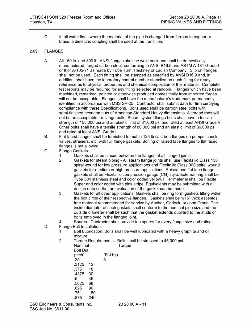
UTHSC-H SON 520 Freezer Room and Offices Section 23 20 00.A, Page 11Houston, TX PIPING VALVES AND FITTINGS
E&C Engineers & Consultants Inc. 23 20 00.A - 11 E&C Job No. 3611.00
C. In all water lines where the material of the pipe is changed from ferrous to copper or brass, a dielectric coupling shall be used at the transition.
2.09 FLANGES:
A. All 150 lb. and 300 lb. ANSI flanges shall be weld neck and shall be domestically manufactured, forged carbon steel, conforming to ANSI B16.5 and ASTM A-181 Grade I or II or A-105-71 as made by Tube Turn, Hackney or Ladish Company. Slip on flanges shall not be used. Each fitting shall be stamped as specified by ANSI B16.9 and, in addition, shall have the laboratory control number stenciled on each fitting for ready reference as to physical properties and chemical composition of the material. Complete test reports may be required for any fitting selected at random. Flanges which have been machined, remarked, painted or otherwise produced domestically from imported forges will not be acceptable. Flanges shall have the manufacturer's trademark permanently identified in accordance with MSS SP-25. Contractor shall submit data for firm certifying compliance with these Specifications. Bolts used shall be carbon steel bolts with semi-finished hexagon nuts of American Standard Heavy dimensions. Allthread rods will not be an acceptable for flange bolts. Steam system flange bolts shall have a tensile strength of 105,000 psi and an elastic limit of 81,000 psi and rated at least ANSI Grade V. Other bolts shall have a tensile strength of 80,000 psi and an elastic limit of 36,000 psi and rated at least ANSI Grade I.
B. Flat faced flanges shall be furnished to match 125 lb cast iron flanges on pumps, check valves, strainers, etc. with full flange gaskets. Bolting of raised face flanges to flat faced flanges is not allowed.
C. Flange Gaskets1. Gaskets shall be placed between the flanges of all flanged joints.2. Gaskets for steam piping - All steam flange joints shall use Flexitallic Class 150
spiral wound for low pressure applications and Flexitallic Class 300 spiral wound gaskets for medium or high pressure applications. Raised and flat face flange gaskets shall be Flexitallic compression gauge (CG) style. External ring shall be Type 304 stainless steel and color coded yellow. Filler material shall be Flexite Super and color coded with pink stripe. Equivalents may be submitted with all design data so that an evaluation of the gasket can be made.
3. Gaskets for all other applications: Gaskets shall be ring form gaskets fitting within the bolt circle of their respective flanges. Gaskets shall be 1/16” thick asbestos free material recommended for service by Anchor, Garlock, or John Crane. The inside diameter of such gaskets shall conform to the nominal pipe size and the outside diameter shall be such that the gasket extends outward to the studs or bolts employed in the flanged joint.
4. Spares - Contractor shall provide ten spares for every flange size and rating.D. Flange Bolt Installation:
1. Bolt Lubrication: Bolts shall be well lubricated with a heavy graphite and oil mixture.
2. Torque Requirements - Bolts shall be stressed to 45,000 psi.Nominal TorqueBolt Dia.(Inch) (Ft-Lbs).25 6.3125 12.375 18.4375 30.5 45.5625 68.625 90.75 150.875 240

UTHSC-H SON 520 Freezer Room and Offices Section 23 20 00.A, Page 12Houston, TX PIPING VALVES AND FITTINGS
E&C Engineers & Consultants Inc. 23 20 00.A - 12 E&C Job No. 3611.00
1.0 3681.125 5331.25 7501.375 10201.5 1200
3. Torque shall be checked with a calibrated breaking action torque wrench on the final torque round. Bolts shall be cold and hot torqued.
4. Torque Pattern - Shall be a cross or star pattern with at least four passes. Limit each pass to 30% of full torque increases.
5. Hot Torque - Re-torque the flange bolts with system at normal operating pressure and temperature for at least four hours.
6. Inspection - Owner shall verify hot torquing of all medium and high pressure steam flange bolts.
PART 3 EXECUTION
Refer to other Sections for service specific requirements.
3.01 EXAMINATION
A. Verify excavations under provisions of Section 23 00 00.B. Verify that excavations are to required grade, dry, and not over-excavated.
3.02 PREPARATION
A. Ream pipe and tube ends. Remove burrs. Bevel plain end ferrous pipe.B. Remove scale and dirt, on inside and outside, before assembly.C. Prepare piping connections to equipment with flanges or unions.
3.03 INSTALLATION
A. Provide non-conducting dielectric connections wherever jointing dissimilar metals.B. Route piping in orderly manner and maintain gradient.C. Install piping to conserve building space and not interfere with use of space.D. Group piping whenever practical at common elevations.E. Install piping to allow for expansion and contraction without stressing pipe, joints, or
connected equipment.F. Provide clearance for installation of insulation and access to valves and fittings.G. Provide access where valves and fittings are not exposed. Coordinate access door
location with architectural features.H. Establish elevations of buried piping outside the building to ensure a minimum of cover.
Refer to Section 23 00 00.I. Where pipe support members are welded to structural building framing, scrape, brush
clean, and apply one coat of zinc rich primer to welding.J. Provide support for utility meters in accordance with requirements of utility companies.K. Prepare pipe, fittings, supports, and accessories not prefinished, ready for finish painting.
Refer to Division 09.L. Excavate in accordance with Section 23 00 00 for work of this Section.M. Backfill in accordance with Section 23 00 00 for work of this Section.N. Install bell and spigot pipe with bell end upstream.O. Install valves with stems upright or horizontal, not inverted.
3.04 ERECTION TOLERANCES
A. Establish invert elevations, slopes for drainage to 1/8 inch per foot (one percent) minimum. Maintain gradients through each joint of pipe and throughout system.

UTHSC-H SON 520 Freezer Room and Offices Section 23 20 00.A, Page 13Houston, TX PIPING VALVES AND FITTINGS
E&C Engineers & Consultants Inc. 23 20 00.A - 13 E&C Job No. 3611.00
B. Slope water piping and arrange to drain at low points.
END OF SECTION


UTHSC-H SON 520 Freezer Room and Offices Section 23 21 00, Page 1Houston, TX HYDRONIC PIPING
E&C Engineers & Consultants Inc. 23 21 00 - 1 E&C Job No. 3611.00
SECTION 23 21 00
HYDRONIC PIPING
PART 1 GENERAL
1.01 The following sections are to be included as if written herein:
A. Section 23 00 00 – Basic Mechanical RequirementsB. Section 23 05 29 – Sleeves, Flashings, Supports and AnchorsC. Section 23 05 53 – Mechanical Identification
1.02 WORK INCLUDED
A. Pipe and pipe fittings.B. Valves.C. Chilled water piping system.
1.03 SCOPE OF WORK
A. Furnish and install all labor, materials, equipment, tools and services and perform all operations required in connection with, or properly incidental to, the construction of complete HVAC piping and accessories systems as indicated on the Drawings, reasonably implied therefrom, or as specified herein unless specifically excluded.
1.04 RELATED WORK
A. Section 08 31 13 - Access Doors.B. Section 09 91 00 - Painting.C. Section 23 00 00 - Basic Mechanical RequirementsD. Section 23 20 00.A - Piping, Valves and FittingsE. Section 21 05 29 - Sleeves, Flashings, Supports and Anchors.F. Section 23 05 53 - Mechanical Identification.G. Section 23 07 19 - Piping Insulation.H. Section 23 06 20 - Hydronic Specialties.
1.05 REFERENCES
A. ANSI/ASME - Boiler and Pressure Vessel Code.B. ANSI/ASME Sec 9 - Welding and Brazing Qualifications.C. ANSI/ASME B16.3 - Malleable Iron Threaded Fittings Class 150 and 300.D. ANSI/ASME B16.23 - Cast Copper Alloy Solder Joint Drainage Fittings - DWV.E. ANSI/ASME B16.29 - Wrought Copper and Wrought Copper Alloy Solder Joint Drainage
Fittings - DWV.F. ANSI/ASME B31.9 - Building Services Piping.G. ANSI/ASTM D2466 - Poly (Vinyl Chloride) (PVC) Plastic Pipe Fittings, Schedule 40.H. ANSI/AWS A5.8 - Brazing Filler Metal.I. ANSI/AWS D1.1 - Structural Welding Code.J. ANSI/AWWA C105 - Polyethylene Encasement for Ductile Iron Piping for Water and
Other Liquids.K. ANSI/AWWA C110 - Ductile - Iron and Gray - Iron Fittings 3 in. through 48 in., for Water
and Other Liquids.L. ANSI/AWWA C111 - Rubber-Gasket Joints for Ductile Iron and Gray-Iron Pressure Pipe
and Fittings.
UTHSC-H SON 520 Freezer Room and Offices Section 23 21 00, Page 2Houston, TX HYDRONIC PIPING
E&C Engineers & Consultants Inc. 23 21 00 - 2 E&C Job No. 3611.00
M. ANSI/AWWA C151 - Ductile-Iron Pipe, Centrifugally Cast in Metal Molds or Sand-Lined Molds, for Water or Other Liquids.
N. ASTM A135 - Pipe, Steel, Black and Hot-Dipped Zinc Coated, Welded and Seamless.O. ASTM A234 - Pipe Fittings of Wrought Carbon Steel and Alloy Steel for Moderate and
Elevated Temperatures.P. ASTM B32 - Solder Metal.Q. ASTM B88 - Seamless Copper Water Tube.R. ASTM D1785 - Poly (Vinyl Chloride) (PVC) Plastic Pipe, Schedules 40, 80, and 120.S. ASTM D2235 - Solvent Cement for Acrylonitrile-Butadiene-Styrene (ABS) Plastic Pipe
and Fittings.T. ASTM D2241 - Poly (Vinyl Chloride) (PVC) Plastic Pipe (SDR-PR).U. ASTM D2310 - Machine-Made Reinforced Thermosetting Resin Pipe.V. ASTM D2466 - Socket-Type PVC Plastic Type Fittings, Schedule 40.W. ASTM D2467 - Socket-Type PVC Plastic Type Fittings, Schedule 80.X. ASTM D2680 - Acrylonitrile-Butadiene-Styrene (ABS) Composite-Sewer Piping.Y. ASTM D2683 - Socket-Type Polyethylene Fittings for Outside Diameter-Controlled
Polyethylene Pipe and Tubing.Z. ASTM D2751 - Acrylonitrile-Butadiene-Styrene (ABS) Sewer Pipe and Fittings.AA. ASTM D2855 - Making Solvent-Cemented Joints with PVC Pipe and Fittings.BB. ASTM F477 - Elastomeric Seals (Gaskets) for Joining Plastic Pipe.
1.06 REGULATORY REQUIREMENTS
A. Conform to ANSI/ASME B31.9.
1.07 QUALITY ASSURANCE
A. Valves: Manufacturer's name and pressure rating marked on valve body.B. Welding Materials and Procedures: Conform to ANSI/ASME SEC. 9, and applicable state
labor regulations.C. Welders Certification: In accordance with ANSI/AWS D1.1.
1.08 SUBMITTALS
A. Submit product data under provisions of Section 23 00 00.B. Include data on pipe materials, pipe fittings, valves, and accessories.C. Include welders certification of compliance with ANSI/AWS D1.1.
1.09 DELIVERY, STORAGE, AND HANDLING
A. Deliver products to site under provisions of Section 23 00 00.B. Store and protect products under provisions of Section 23 00 00.C. Deliver and store valves in shipping containers with labeling in place.
PART 2 PRODUCTS
2.01 WALL, FLOOR AND CEILING PLATES:
A. See Section 23 05 29.
2.02 SLEEVES, INSERTS, AND FASTENINGS:
A. See Section 23 05 29.

UTHSC-H SON 520 Freezer Room and Offices Section 23 21 00, Page 3Houston, TX HYDRONIC PIPING
E&C Engineers & Consultants Inc. 23 21 00 - 3 E&C Job No. 3611.00
2.03 CHILLED AND HEATING WATER PIPING - ABOVE GROUND:
A. See Section 23 20 00.A and 23 06 20. 1. All piping shall be Standard Weight black steel seamless pipe.2. All unions: Class 300.3. Low Zone (0' to 150' elevation)
a. Fittings on piping 2-1/2" and larger shall be standard weight butt welding type. Flanges shall be 150# welding neck type. Standard weight Weld-O-Lets, Thread-O-Lets, and shaped nipples may be used only when take-off is 1/3 or less nominal size of main. Bushings shall not be used.
b. Fittings on piping 2" and smaller shall be Class 150 black malleable iron screw fittings. (Class 300 for unions.)
c. Valves and strainers: Class 150.
2.04 Equipment Drain Piping:
A. All factory fabricated or field erected air conditioning units with drain pans, all centrifugal water pumps and all other items or equipment or apparatus that require drains shall be connected with drain line run with adequate slope to a floor drain or other point of discharge as shown on the Drawings. On A.C. units the drain line shall include a properly sized water-sealed trap.
B. All drain piping shall be one inch (1") size minimum or larger as may be indicated on the Drawings. Such piping shall be Type L hard copper tube. The drain piping shall be assembled with adapter tees at each change in direction. Install screw plugs in unused openings for access to rod and clean.
PART 3 EXECUTION
3.01 PREPARATION
A. Ream pipe and tube ends. Remove burrs. Bevel plain end ferrous pipe.B. Remove scale and dirt on inside and outside before assembly.C. Prepare piping connections to equipment with flanges or unions.D. After completion, fill, clean, and treat systems. Refer to Section 22 13 16.
3.02 INSTALLATION
A. Route piping in orderly manner, plumb and parallel to building structure, and maintain gradient.
B. Install piping to conserve building space, and not interfere with use of space and other work.
C. Group piping whenever practical at common elevations.D. Install piping to allow for expansion and contraction without stressing pipe, joints, or
connected equipment. Refer to Section 23 05 16.E. Provide clearance for installation of insulation, and access to valves and fittings.F. Provide access where valves and fittings are not exposed. Coordinate size and location
of access doors with Section 08 31 13.G. Slope piping and arrange systems to drain at low points. Use eccentric reducers to
maintain top of pipe level.H. Where pipe support members are welded to structural building framing, scrape, brush
clean, and apply one coat of zinc rich primer to weld area.I. Prepare pipe, fittings, supports, and accessories for finish painting. Refer to Section 09
91 00.J. Install valves with stems upright or horizontal, not inverted.

UTHSC-H SON 520 Freezer Room and Offices Section 23 21 00, Page 4Houston, TX HYDRONIC PIPING
E&C Engineers & Consultants Inc. 23 21 00 - 4 E&C Job No. 3611.00
K. Piping taps shall be made off of the top half of the pipe. Either off of the top or at a 45 degree angle up..
3.03 FABRICATION OF PIPE:
A. All the various piping systems shall be made up straight and true and run at proper grades to permit proper flow of the contained material. Lines shall also be graded for proper drainage.
B. Piping shall follow as closely as possible the routes shown on Drawings which take into consideration conditions to be met at the site.
C. Should any unforeseen conditions arise, lines shall be changed or rerouted as required after proper approval has been obtained.
D. All piping shall be installed with due regard to expansion and contraction and so as to prevent excessive strain and stress in the piping, in connections, and in equipment to which the lines are connected.
E. All piping shall be clean when it is installed. Before installation it shall be checked, upended, swabbed, if necessary, and all rust or dirt from storage or from laying on the ground shall be removed.
F. Procedure of Assembling Screw Pipe Fittings: All screw joints shall be made with taper threads, properly cut. Joints shall be made tight with Teflon applied to the pipe threads only and not to fittings. When threads are cut on pipes, the ends shall be carefully reamed to remove any burrs. Before installing pipe that has been cut and threaded, the lengths of pipe shall be upended and hammered to remove all shavings and foreign material.
G. Procedure for Assembling Other Joints: Procedures for assembling joints in cast iron and copper lines have been set forth elsewhere in these Specifications. For any special materials, consult the manufacturers for the recommended procedures in assembling the joints.
3.04 APPLICATION
A. Roll grooved mechanical couplings and fasteners may be used only for pump fit-up assemblies.
B. Install unions downstream of valves and at equipment or apparatus connections.C. Install brass male adapters each side of valves in copper piped system. Sweat solder
adapters to pipe.D. Install butterfly valves for shut-off and to isolate equipment, part of systems, or vertical
risers.E. Install butterfly valves for throttling, bypass, or manual flow control services.F. Provide spring loaded check valves on discharge of condenser water pumps.G. Use gas plug cocks for throttling service. Use non-lubricated plug cocks only when
shut-off or isolating valves are also provided.H. Use butterfly valves in heating, chilled and condenser water systems.I. Use only butterfly valves in chilled and condenser water systems for throttling and
isolation service.J. Use lug end butterfly valves to isolate equipment.K. Provide 3/4 inch (20 mm) ball drain valves at main shut-off valves, low points of piping,
bases of vertical risers, and at equipment. Pipe to nearest drain.
3.05 PIPE PRESSURE TESTS:
A. See Section 23 00 00.

UTHSC-H SON 520 Freezer Room and Offices Section 23 21 00, Page 5Houston, TX HYDRONIC PIPING
E&C Engineers & Consultants Inc. 23 21 00 - 5 E&C Job No. 3611.00
3.06 CLEANING AND FLUSHING OF WATER SYSTEMS
A. Water circulating Systems shall be thoroughly cleaned before placing in operation to rid systems of rust, dirt, piping compound, mill scale, oil, grease, any and all other material foreign to water being circulated.
B. Extreme care shall be exercised during construction to prevent dirt and other foreign matter from entering the pipe or other parts of systems. Pipe stored on the project shall have open ends capped and equipment shall have openings fully protected. Before erection, each piece of pipe, fitting, or valve shall be visually examined and dirt removed.
C. At pipe end locations a temporary bypass will be installed. Bypass shall be same size as the supply and return pipe. Prior to flushing the distribution system, the Contractor shall install the temporary bypass and a temporary line size strainer between the supply and return pipes. Contractor shall verify that the isolation valves are open.
D. After the temporary bypasses are installed, the Contractor shall provide and operate one pump which will cause a velocity of 10 feet per second in the main piping. This pump will be provided with a shot chemical feeder and a strainer assembly. Pump shall be connected to system at the point where piping goes into the building from the tunnel. If the pump is electric driven, rather than engine driven, the Contractor shall provide all temporary electrical disconnects, wiring, fuses, and other electrical devices that are required for safe operation.
E. Circulation will be started using the temporary pump. A nonhazardous cleaning compound (Entec 324 or approved equal) shall be added using the shot feeder until the concentration level of 20 parts per million is reached. Once this 20 parts per million concentration is reached, circulation will be maintained for 48 hours. After this period of time, the cleaning water shall be dumped to the sanitary sewer.
F. The distribution system will then be refilled with city water and circulated with continual bleed and make-up until the water is certified clean by the water treatment consultant, and accepted by the Owner. At the completion of this step an inhibitor shall be introduced. All waste water shall be dumped into the sanitary sewer system.
G. After the system is certified as clean, the Contractor shall close the valves. The bypass piping shall be removed as final connections to the building are accomplished.
H. During the flushing procedure, strainers shall be cleaned as often as necessary to remove debris and, in any event, all strainers shall be cleaned by physically removing the strainer screen from the body of the strainer at the end of flushing. Replace strainer basket and gasket. Contractor shall not flush through control valves, coils, etc. Contractor shall provide temporary bypasses at coils and spool pieces at control valves. Flush the coils individually wasting water to sanitary sewer. Connect coils and install control valves after flushing.
I. Test samples shall be taken at all bypass locations and all tests shall indicate that the entire system has reached a PH, conductivity, and chemical concentration 1evel as approved by the Owner to match present systems. Contractor shall purchase needed chemicals from Owner’s chemical treatment supplier.
J. Contractor shall provide a smaller assembly to clean and flush any miscellaneous piping that can not be included in the initial system flush. All other criteria shall remain the same.
K. Contractor shall add inhibitor to the cleaning and flushing chemicals if, once the system is approved as clean, there is any delay in connecting the new system to the existing system. This is to prevent any corrosion after the new pipe is clean.
END OF SECTION


UTHSC-H SON 520 Freezer Room and Offices Section 23 31 00, Page 1Houston, TX DUCTWORK
E&C Engineers & Consultants Inc. 23 31 00 - 1 E&C Job No. 3611.00
SECTION 23 31 00DUCTWORK
PART 1GENERAL
1.00 The following sections are to be included as if written herein:
A. Section 23 00 00 – Basic Mechanical Requirements
B. Section 23 05 29 – Sleeves, Flashings, Supports and Anchors
C. Section 23 05 53 – Mechanical Identification
1.01 WORK INCLUDED
A. Low pressure ducts.
1.02 RELATED WORK
A. Section 09 91 00 - Painting: Weld priming, weather resistant, paint or coating.
B. Section 23 00 00 - Basic Mechanical Requirements.
C. Section 23 05 29 - Sleeves, Flashings, Supports and Anchors.
E. Section 23 07 13 - Duct Insulation.
F. Section 23 33 00 - Ductwork Accessories.
G. Section 23 05 93.A - Testing, Adjusting and Balancing.
1.03 REFERENCES
A. ASHRAE - Handbook of Fundamentals; Duct Design.
B. ASHRAE - Handbook of Equipment; Duct Construction.
C. ASTM A 90 - Weight of Coating on Zinc-Coated (Galvanized) Iron or Steel Articles.
D. ASTM A 167 - Stainless and Heat-Resisting Chromium-Nickel Steel Plate, Sheet, and Strip.
E. ASTM A 525 - General Requirements for Steel Sheet, Zinc-Coated (Galvanized) by the Hot-Dip Process.
F. ASTM A 527 - Steel Sheet, Zinc-Coated (Galvanized) by Hot-Dip Process, Lock Forming Quality.
G. ASTM B209 - Aluminum and Aluminum Alloy Sheet and Plate.
H. ASTM C 14 - Concrete Sewer, Storm Drain, and Culvert Pipe.
I. ASTM C 443 - Joints for Circular Concrete Sewer and Culvert Pipe, Using Rubber Gaskets.
J. NFPA 90A - Installation of Air Conditioning and Ventilating Systems.
UTHSC-H SON 520 Freezer Room and Offices Section 23 31 00, Page 2Houston, TX DUCTWORK
E&C Engineers & Consultants Inc. 23 31 00 - 2 E&C Job No. 3611.00
K. NFPA 90B - Installation of Warm Air Heating and Air Conditioning Systems.
L. NFPA 96 - Installation of Equipment for the Removal of Smoke and Grease-Laden Vapors from Commercial Cooling Equipment.
M. SMACNA - Low Pressure Duct Construction Standards.
N. SMACNA - High Pressure Duct Construction Standards.
O. UL 181 - Factory-Made Air Ducts and Connectors.
1.04 REFERENCES
A. Fundamentals Handbook, American Society of Heating, Refrigerating, and Air Conditioning Engineers (ASHRAE).
B. Equipment Handbook, ASHRAE.
C. HVAC Duct Construction Standards, Sheet Metal and Air Conditioning Contractors National Association (SMACNA).
D. HVAC Duct System Design, SMACNA.
E. Round Industrial Duct Construction Standards, SMACNA.
F. Engineering Design Manual for Air Handling Systems, United McGill Corporation (UMC).
G. Assembly and Installation of Spiral Duct and Fittings, UMC.
H. Engineering Report No. 132 (Spacing of Duct Hangers), UMC.
1.05 DEFINITIONS
A. Duct Sizes: Inside clear dimensions. For lined ducts, maintain sizes inside lining.
B. Low Pressure: 2 inch WG positive or negative static pressure and velocities less than 1,500 fpm.
C. Medium Pressure: 6 inch WG positive static pressure and velocities greater than 1,500 fpm.
1.06 REGULATORY REQUIREMENTS
A. Construct ductwork to NFPA 90A, NFPA 90B and NFPA 96 standards.
1.07 SUBMITTALS
A. Shop Drawings shall be submitted on all items of sheet metal work specified herein. Shop Drawings of ductwork at air units shall be submitted at a minimum scale of 3/8" equal to one foot.
B. Shop Drawings shall be submitted on all other ductwork per Section 23 00 00. Shop Drawings shall indicate location of all supply, return, exhaust and light fixtures from the approved reflected ceiling plans.
C. Submit shop drawings and product data under provisions of Section 23 00 00.

UTHSC-H SON 520 Freezer Room and Offices Section 23 31 00, Page 3Houston, TX DUCTWORK
E&C Engineers & Consultants Inc. 23 31 00 - 3 E&C Job No. 3611.00
D. Submit samples under provisions of Section 23 00 00.
1.08 DELIVERY, STORAGE, AND HANDLING
A. Deliver products to site under provisions of Section 23 00 00.
B. Store and protect products under provisions of Section 23 00 00.
PART 2PRODUCTS
2.01 DUCTWORK GENERAL:
A. All ductwork indicated on the Drawings, specified or required for the air conditioning and ventilating systems shall be of materials as hereinafter specified unless indicated otherwise. All air distribution ductwork shall be fabricated, erected, supported, etc., in accordance with all applicable standards of SMACNA Duct Manuals where such standards do not conflict with NFPA 90A and where class of construction equals or exceeds that noted herein. All exhaust ductwork including toilet room exhausts shall be constructed and leak tested as specified for medium pressure supply ducts at negative pressure.
B. All ductwork shown on the Drawings, specified or required for the heating, ventilating and air conditioning systems shall be constructed and erected in a first class workmanlike manner. The work shall be guaranteed for a period of one (1) year from and after the date of acceptance of the job against noise, chatter, whistling, vibration, and free from pulsation under all conditions of operation. After the system is in operation, should these defects occur, they shall be corrected as directed by the Architect.
C. All duct sizes shown on the Drawings are air stream sizes. Allowance shall be made for internal lining where required, to provide the required cross sectional area.
D. All holes in ducts for damper rods and other necessary devices shall be either drilled or machine punched (not pin punched), and shall not be any larger than necessary. All duct openings shall be provided with sheet metal caps if the openings are to be left unconnected for any length of time.
E. Except for special ducts specified elsewhere herein, all sheet metal used on the project shall be constructed from prime galvanized steel sheets and/or coils up to 60" in width. Each sheet shall be stenciled with manufacturer's name and gauge. Coils of sheet steel shall be stenciled throughout on ten foot (10') centers with manufacturer's name and must be visible after duct is installed. Sheet metal must conform to SMACNA sheet metal tolerances as outlined in SMACNA's "HVAC Duct Construction Standards."
F. Where ducts, exposed to view (including equipment rooms), pass through walls, floors or ceilings, furnish and install sheet metal collars around the duct.
2.02 DUCTWORK LOW PRESSURE:
A. The scope of low pressure ductwork is defined as all ductwork downstream of terminal units. Construction of all low pressure duct shall be in accordance with Low Velocity Duct Construction Standards as published by Sheet Metal and Air Conditioning Contractors National Association (SMACNA) and shall be sealed and tested at 3" static with the same test procedures as medium pressure ductwork.
B. Spiral wound round duct shall be as manufactured by United McGill Sheet Metal Company or approved equal.

UTHSC-H SON 520 Freezer Room and Offices Section 23 31 00, Page 4Houston, TX DUCTWORK
E&C Engineers & Consultants Inc. 23 31 00 - 4 E&C Job No. 3611.00
C. The metal gauges listed in the 1985 SMACNA HVAC Duct Construction Standards for Metal and Flexible Duct are the minimum which shall be used for this project if not otherwise specified herein. It shall be noted that the Contractor is responsible that the metal gauge selected is heavy enough to withstand the physical abuse of the installation.
D. Elbows shall be radius type and have a centerline radius of 1-1/2 times the duct diameter or width. Elbows in round ducts may be smooth radius as described above or 5-piece 90 degree elbows and 3-piece 45 degree elbows. Joints in round ducts shall be slip type with a minimum of three sheet metal screws. Joints in sectional elbows shall be sealed as specified for duct sealing.
E. SEALANT: All ductwork (except welded exhaust duct) shall be sealed with either "MP" (Multi-Purpose), Hardcast "Iron-grip 601", Hardcast “Flex-Grip 550 (spray applied to 20 mil thickness), or "United Duct Seal" (United McGill Corp.) water base, latex or acrylic type sealant. Note that, except as noted, oil or solvent based sealants are specifically prohibited for use on this project. For exterior applications, "Uni-Weather" (United McGill Corp.) neoprene based sealant shall be used. No other sealants may be used. All seams and joints in shop and field fabricated ductwork shall be sealed by applying one layer of sealant, then immediately spanning the joint with a single layer of 3" wide open weave fiberglass tape. Sufficient additional sealant shall then be applied to completely imbed the cloth. All sealants shall be UL rated at no more than flame spread of 5 and smoke developed of 0. At contractor’s option Hardcast 1602 sealant tape may be used in lap joints and flat seams.
2.03 DUCTWORK MEDIUM PRESSURE:
A. The scope of medium pressure ductwork is defined as all ductwork downstream of all air handlers, up to and including terminal units, plus all exhaust air ductwork. Construction of all ducts shall be in accordance with High Velocity Construction Standards as published by SMACNA. All round and rectangular duct construction, duct fittings, dampers, etc., are covered in this manual and it is to be adhered to.1. Spiral wound round duct shall be as manufactured by United McGill Sheet Metal
Company or approved equal.2. The metal gauges are listed herein for round duct and for rectangular duct.
B. All ductwork (except welded exhaust duct) shall be sealed with either "MP" (Multi-Purpose), Hardcast "Iron-grip 601", or "United Duct Seal" (United McGill Corp.) water base, latex or acrylic type sealant. Note that, except as noted, oil or solvent based sealants are specifically prohibited for use on this project. For exterior applications, "Uni-Weather" (United McGill Corp.) solvent based sealant shall be used. No other sealants may be used. All seams and joints in shop and field fabricated ductwork shall be sealed by applying one layer of sealant, then immediately spanning the joint with a single layer of 3" wide open weave fiberglass tape. Sufficient additional sealant shall then be applied to completely imbed the cloth. At contractor’s option Hardcast 1602 sealant tape may be used in lap joints and flat seams.
C. Oval ducts shall be spiral flat oval or welded flat oval equal to those of United McGill Sheet Metal Company with gauges and reinforcing as recommended by the manufacturer for medium pressure or the ducts may be Shop fabricated of completely welded construction of the following gauge:
Major Axis 12 to 20 No. 24 gauge
Major Axis 20 to 30 No. 22 gauge
Major Axis 30 to 46 No. 20 gauge

UTHSC-H SON 520 Freezer Room and Offices Section 23 31 00, Page 5Houston, TX DUCTWORK
E&C Engineers & Consultants Inc. 23 31 00 - 5 E&C Job No. 3611.00
Major Axis 46 to 50 No. 18 gauge
Major Axis 50 and Up No. 16 gauge
D. Oval fittings shall be equal to those of United McGill Sheet Metal Company with requirements, sealing, etc., similar to that specified for round medium pressure work.
E. Oval duct reinforcing methods shall be submitted as Shop Drawings for approval. Reinforcing galvanized angles shall be of sizes specified for same size rectangular ducts. Galvanized angles shall be used where standing seams are specified for rectangular ducts. Attaching methods shall be shown on Shop Drawings and submitted for approval.
F. Testing of Medium Pressure Ductwork: (Includes from fan discharge through to the discharge of terminal units.)
1. All medium pressure ducts shall be pressure tested according to SMACNA Chapter 10 test procedures. Design pressure for testing ductwork shall be six inches (6") of water. Total allowable leakage shall not exceed 1% of the total system design air flow rate. When partial sections of the duct system are tested, the summation of the leakage for all Sections shall not exceed the total allowable leakage.
1. The entire system of medium pressure ductwork shall be tested, excluding the VAV/Constant Volume Terminal Units (i.e. The ductwork shall be capped immediately prior to the Terminal Units, and tested as described above). After testing has proven that the ductwork is installed and performs as specified, the terminal units shall be connected to the ductwork and the connections sealed with extra care. The contractor shall inform the project inspector when the joints may be visually inspected for voids, splits, or improper sealing of the joints. If any leakage in the terminal unit connections/joints after the systems have been put into service, the leaks shall be repaired by: 1) complete removal of the sealing materials, 2) thorough cleaning of the joint surfaces, and 3) installation of multiple layers of sealing materials.
G. All exhaust ductwork, including toilet room exhausts, shall be constructed as for medium pressure ducts and shall be tested for leaks in the same manner as for medium pressure supply ducts. Testing may exclude any zoning valves as well. The duct shall be capped upstream and downstream of the valves and tested on both sides. Testing can be done before spin-ins are installed if there is no sheetmetal ductwork after the spin-in, or an additional 1 cfm can be added to the total allowable cfm leakage for each dampered spin-in. The total leakage for both upstream and downstream shall be no more than 1% of the total design cfm.
H. DUCTMATE or Ward coupling system may be used on rectangular ductwork. Contractor may (where space permits) use rectangular ductwork with DUCTMATE or Ward system in lieu of oval ductwork. Joints shall be assembled with pre-formed isobutyene gasket (min. 3/16” thick x 5/8” wide), equal to Ductmate 440 tape or McGill “Uni-Butyl” tape. After assembly, entire joint shall be coated with 20 mil thickness of Hardcast “Flex-Grip” 550. No other flange-type duct joining systems may be used. Duct gauges shall be as specified herein.
I. Rectangular 90 degree elbows shall be constructed with single thickness turning vanes. Radius type rectangular elbows shall have a centerline radius of 1-1/2 times the duct diameter or width. Contractor shall have the option to substitute short radius vaned elbows, but shall request the substitution at the time of submittal of Shop Drawings, and shall request the substitution as required in Section 23 0000. Elbows in round or oval ducts may be smooth long radius as described above or 5-piece 90 degree elbows and 3-piece 45 degree elbows. Joints in round ducts shall be slip type with a minimum of three sheet metal screws. Joints in sectional elbows shall be sealed as specified for duct sealing.

UTHSC-H SON 520 Freezer Room and Offices Section 23 31 00, Page 6Houston, TX DUCTWORK
E&C Engineers & Consultants Inc. 23 31 00 - 6 E&C Job No. 3611.00
2.04 ELBOWS:
A. Where rectangular elbows are shown, or are required for good air flow, contractor shall provide and install turning vanes. Job fabricated turning vanes, if used, shall be fabricated of the same gauge and type of material as the duct in which they are installed. Vanes must be fabricated for same angle as duct offset. Radius elbows shall have a centerline radius of not less than one and one-half (1-1/2) times the duct width. Submit Shop Drawings on factory fabricated and job fabricated turning vanes. Provide turning vanes in all rectangular radius elbows and offsets.
B. All turning vanes shall be anchored to the cheeks of the elbow in such a way that the cheeks will not breathe at the surfaces where the vanes touch the cheeks. In most cases, this will necessitate the installation of an angle iron support on the outside of the cheek parallel to the line of the turning vanes.
C. Where turning vanes are to be provided and installed as required above. Only single thickness turning vanes shall be used.
2.05 FLEXIBLE DUCTS:
B. Insulated Acoustical Low Pressure Flexible Duct: Provide where indicated on drawings Flexmaster Type 1M UL181 Class I Air Duct. The duct shall be constructed of a CPE fabric supported by helical wound galvanized steel. The fabric shall be mechanically locked to the steel helix without the use of adhesives or chemicals. This flex duct material shall be used on exhaust duct for connecting air inlets (for general lab exhaust, not to be considered for connections to hoods, BSCs or equipment connections) to the distribution duct.
The internal working pressure rating shall be at least 6" w.g. positive and 4" w.g. negative with a bursting pressure of at least 2½ time the working pressure.
The duct shall be rated for a velocity of at least 4000 feet per minute. The duct must be suitable for continuous operation at a temperature range of -20° F to +250° F.
Acoustical performance, when tested by an independent laboratory in accordance with the Air Diffusion Council's Flexible Air Duct Test Code FD 72-R1, Section 3.0, Sound Properties, shall be as follows:
The insertion loss (dB) of a 10 foot length of straight duct when tested in accordance with ASTM E477, at a velocity of 2500 feet per minute, shall be at least:
Octave Band 2 3 4 5 6 7Hz. 125 250 500 1000 2000 4000
6" diameter 7 31 40 38 40 278" diameter 13 29 36 35 38 2212" diameter 21 28 29 33 26 12
The radiated noise reduction (dB) of a 10 foot length of straight duct when tested in accordance with ASTM E477, at a velocity of 2500 feet per minute, shall be at least:
Octave Band 2 3 4 5 6 7Hz. 125 250 500 1000 2000 4000
6" diameter 5 8 7 8 11 158" diameter 10 7 7 8 10 1312" diameter 9 6 6 5 9 13
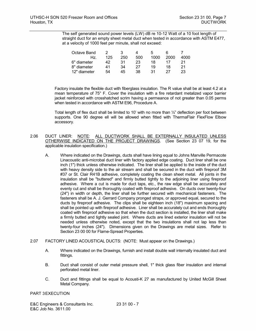
UTHSC-H SON 520 Freezer Room and Offices Section 23 31 00, Page 7Houston, TX DUCTWORK
E&C Engineers & Consultants Inc. 23 31 00 - 7 E&C Job No. 3611.00
The self generated sound power levels (LW) dB re 10-12 Watt of a 10 foot length of straight duct for an empty sheet metal duct when tested in accordance with ASTM E477, at a velocity of 1000 feet per minute, shall not exceed:
Octave Band 2 3 4 5 6 7Hz. 125 250 500 1000 2000 4000
6" diameter 42 31 23 18 17 218" diameter 41 34 27 19 18 2112" diameter 54 45 38 31 27 23
Factory insulate the flexible duct with fiberglass insulation. The R value shall be at least 4.2 at a mean temperature of 75° F. Cover the insulation with a fire retardant metalized vapor barrier jacket reinforced with crosshatched scrim having a permeance of not greater than 0.05 perms when tested in accordance with ASTM E96, Procedure A.
Total length of flex duct shall be limited to 10’ with no more than ½” deflection per foot between supports. One 90 degree ell will be allowed when fitted with ThermaFlair FlexFlow Elbow accessory.
2.06 DUCT LINER: NOTE: ALL DUCTWORK SHALL BE EXTERNALLY INSULATED UNLESS OTHERWISE INDICATED ON THE PROJECT DRAWINGS. (See Section 23 07 19, for the applicable insulation specification.)
A. Where indicated on the Drawings, ducts shall have lining equal to Johns Manville Permacote Linacoustic anti-microbal duct liner with factory applied edge coating. Duct liner shall be one inch (1") thick unless otherwise indicated. The liner shall be applied to the inside of the duct with heavy density side to the air stream and shall be secured in the duct with fireproof 3M #37 or St. Clair R41B adhesive, completely coating the clean sheet metal. All joints in the insulation shall be "buttered" and firmly butted tightly to the adjoining liner using fireproof adhesive. Where a cut is made for duct taps, etc., the raw edge shall be accurately and evenly cut and shall be thoroughly coated with fireproof adhesive. On ducts over twenty-four (24") in width or depth, the liner shall be further secured with mechanical fasteners. The fasteners shall be A. J. Gerrard Company pronged straps, or approved equal, secured to the ducts by fireproof adhesive. The clips shall be eighteen inch (18") maximum spacing and shall be pointed up with fireproof adhesive. Liner shall be accurately cut and ends thoroughly coated with fireproof adhesive so that when the duct section is installed, the liner shall make a firmly butted and tightly sealed joint. Where ducts are lined exterior insulation will not be needed unless otherwise noted, except that the two insulations shall not lap less than twenty-four inches (24"). Dimensions given on the Drawings are metal sizes. Refer to Section 23 00 00 for Flame-Spread Properties.
2.07 FACTORY LINED ACOUSTICAL DUCTS: (NOTE: Must appear on the Drawings.)
A. Where indicated on the Drawings, furnish and install double wall internally insulated duct and fittings.
B. Duct shall consist of outer metal pressure shell, 1" thick glass fiber insulation and internal perforated metal liner.
C. Duct and fittings shall be equal to Acousti-K 27 as manufactured by United McGill Sheet Metal Company.
PART 3EXECUTION
UTHSC-H SON 520 Freezer Room and Offices Section 23 31 00, Page 8Houston, TX DUCTWORK
E&C Engineers & Consultants Inc. 23 31 00 - 8 E&C Job No. 3611.00
3.01 INSTALLATION
A. Refer also to requirements included in Part 2 of this specification.
B. Obtain manufacturer's inspection and acceptance of fabrication and installation of fiberglass ductwork prior to beginning of installation.
C. Provide openings in ductwork where required to accommodate thermometers and controllers. Provide pilot tube openings where required for testing of systems, complete with metal can with spring device or screw to ensure against air leakage. Where openings are provided in insulated ductwork, install insulation material inside a metal ring.
D. Locate ducts with sufficient space around equipment to allow normal operating and maintenance activities.
E. Connect diffusers or troffer boots to low pressure ducts with 2 feet maximum length of flexible duct. Hold in place with strap or clamp, and seal as specified.
F. During construction provide temporary closures of metal or taped polyethylene on open ductwork to prevent construction dust from entering ductwork system.
3.02 LOW PRESSURE DUCT SUPPORTS:
A. See Section 23 05 29.
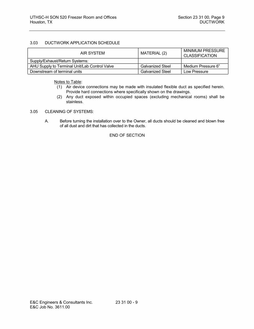
UTHSC-H SON 520 Freezer Room and Offices Section 23 31 00, Page 9Houston, TX DUCTWORK
E&C Engineers & Consultants Inc. 23 31 00 - 9 E&C Job No. 3611.00
3.03 DUCTWORK APPLICATION SCHEDULE
Notes to Table:(1) Air device connections may be made with insulated flexible duct as specified herein.
Provide hard connections where specifically shown on the drawings.(2) Any duct exposed within occupied spaces (excluding mechanical rooms) shall be
stainless.
3.05 CLEANING OF SYSTEMS:
A. Before turning the installation over to the Owner, all ducts should be cleaned and blown free of all dust and dirt that has collected in the ducts.
END OF SECTION
AIR SYSTEM MATERIAL (2) MINIMUM PRESSURECLASSIFICATION
Supply/Exhaust/Return Systems:AHU Supply to Terminal Unit/Lab Control Valve Galvanized Steel Medium Pressure 6”Downstream of terminal units Galvanized Steel Low Pressure

UTHSC-H SON 520 Freezer Room and Offices Section 23 33 00, Page 1Houston, TX DUCTWORK ACCESSORIES
E&C Engineers & Consultants Inc. 23 33 00 - 1 E&C Job No. 3611.00
SECTION 23 33 00DUCTWORK ACCESSORIES
PART 1GENERAL
1.00 The following sections are to be included as if written herein:
A. Section 23 00 00 – Basic Mechanical Requirements
B. Section 23 05 29 – Sleeves, Flashings, Supports and Anchors
C. Section 23 05 53 – Mechanical Identification
1.01 WORK INCLUDED
A. Volume control dampers.
B. Air turning devices.
C. Duct access doors.
D. Duct test holes.
1.02 RELATED WORK
A. Section 23 31 00 - Ductwork.
1.03 REFERENCES
A. NFPA 90A - Installation of Air Conditioning and Ventilating Systems.
B. SMACNA - Low Pressure Duct Construction Standards.
C. UL 33 - Heat Responsive Links for Fire-Protection Service.
D. UL 555 - Fire Dampers and Ceiling Dampers.
1.04 SUBMITTALS
A. Submit shop drawings and product data under provisions of Section 23 00 00.
B. Provide shop drawings for shop fabricated assemblies indicated, including volume control dampers duct access doors duct test holes. Provide product data for hardware used.
C. Submit manufacturer's installation instructions under provisions of Section 23 00 00 for fire dampers and combination fire and smoke dampers.
PART 2PRODUCTS
2.01 DAMPERS:
A. Furnish and install dampers where shown on the Drawings and wherever necessary for complete control of the air flow, including all supply, return and exhaust branches, "division" in main supply, return and exhaust ducts, each individual air supply outlet and fresh air ducts.

UTHSC-H SON 520 Freezer Room and Offices Section 23 33 00, Page 2Houston, TX DUCTWORK ACCESSORIES
E&C Engineers & Consultants Inc. 23 33 00 - 2 E&C Job No. 3611.00
Where access to dampers through a fixed suspended ceiling is necessary, the Contractor shall be responsible for the proper location of the access doors.
B. Dampers shall be carefully fitted, and shall be controlled by locking quadrants equal to Ventlok No. 555 on exposed uninsulated ductwork, No. 644 on exposed externally insulated ductwork and No. 677 (2-5/8" diameter) chromium plated cover plate for concealed ductwork not above lay-in accessible ceilings. Furnish and install end bearings for the damper rods on the end opposite the quadrant when No. 555 or No. 644 regulators are used, and on both ends when No. 677 regulators are used.
C. On concealed ductwork above lay-in accessible ceilings use Ventlok No. 555 or No. 644 locking quadrant for splitter dampers.
D. Dampers larger than three (3) square feet in area shall be controlled by means of rods hinged near the leading edge of the damper with provisions for firmly anchoring the rod and with end bearings supporting the axle.
E. Volume dampers shall be equal to those of Greenheck, Ruskin, Pottorff or substitute approved by Owner. Blades shall not exceed 48 inches (48") in length or twelve inches (12") in width and shall be of the opposed interlocking type. The blades shall be of not less than No. 16 gauge galvanized steel supported on one-half inch (1/2") diameter rust-proofed axles. Axle bearings shall be the self-lubricating ferrule type.
F. Install all dampers furnished by the Temperature Control Manufacturer's in strict accordance with the manufacturer's recommendations and requirements of these Specifications.
G. All adjustable dampers installed in externally insulated ductwork shall be installed with Ventlok No. 639, or equal, elevated dial operators. Insulation shall extend under the elevated dial. All adjustable dampers installed in internally insulated ductwork shall be installed with Ventlok No. 635, or equal, dial operators. All damper shaft penetrations in the ductwork shall be installed with Ventlok #609 end bearings.
2.02 ACCESS DOORS:
A. Furnish and install in the ductwork, hinged rectangular or round "spin-in" access doors to provide access to all fire dampers mixed air plenums, upstream of steam reheat coils, automatic dampers, etc. Where the ducts are insulated, the access doors shall be double skin doors with one inch (1") of insulation in the door. Where the size of the duct permits, the doors shall be eighteen inches (18") by sixteen inches (16"), or eighteen inches in diameter, and shall be provided with Ventlok No. 260 latches (latches are not required in round doors). Latches for rectangular doors smaller than 18" x 16" shall be Ventlok No. 100 or 140. Doors for zone heating coils shall be Ventlok, stamped, insulated access doors, minimum 10" x 12", complete with latch and two (2) hinges, or twelve inches (12") in diameter. Round access doors shall be "Inspector Series" spin-in type door as manufactured by Flexmaster USA, or approved equal. Doors for personnel access to ductwork shall be nominal twenty-four inches (24") in diameter.
B. Where these access doors are above a suspended ceiling, this Contractor shall be responsible for the proper location of the ceiling access doors.
2.03 TEST OPENINGS:
A. Furnish and install in the return air duct and in the discharge duct of each fan unit Ventlok No. 699 instrument test holes. The test holes shall be installed in locations as required to

UTHSC-H SON 520 Freezer Room and Offices Section 23 33 00, Page 3Houston, TX DUCTWORK ACCESSORIES
E&C Engineers & Consultants Inc. 23 33 00 - 3 E&C Job No. 3611.00
measure pressure drops across each item in the system, e.g., O.A. louvers, filters, fans, coils, intermediate points in duct runs, etc.
2.04 DUCT LOW PRESSURE TAPS (Conical Bell Mouth Fittings)
A. All duct taps shall be made with low-loss taps, conical taps or full-sized bellmouth taps.
B. Conical fittings may be used for duct taps and shall include quadrant dampers on all lines to air devices (diffusers and grilles) even though a volume damper is specified for the air device. (This does not apply to medium pressure duct.) Spin-in fittings shall be sealed at the duct tap with a gasket, or compression fit, or sealed with sealant specified for medium pressure ductwork. The location of spin-in fittings in the ducts shall be determined after dual or single duct terminal units are hung or the location of the light fixtures is known so as to minimize flexible duct lengths and sharp bends.
C. The conical fitting shall be made of at least 26 gage galvanized sheet metal. The construction to be a two-piece fitting with a minimum overall length of 6 inches and shall be factory sealed for high pressure requirements. Average loss coefficient for sizes 6, 8, and 10 shall be less than 0.055.
D. Each to be provided with minimum 24 gage damper plate with locking quadrant operator and sealed end bearings. Damper blade shall be securely attached to shaft to prevent damper from rotating around shaft.
E. Provide flange and gasket with adhesive peel-back paper for ease of application. The fitting shall be further secured by sheet metal screws spaced evenly at no more than 4 inches on-center with a minimum of four screws per fitting.
F. The conical bellmouth fitting shall be Series 3000G as manufactured by Flexmaster U.S.A., Inc., or Buckley Air Products, Inc., 'AIR-TITE'.
PART 3EXECUTION
3.01 INSTALLATION
A. Install accessories in accordance with manufacturer's instructions.
B. Provide balancing dampers at points on low pressure supply, return, and exhaust systems where branches are taken from larger ducts as required for air balancing. Use splitter dampers only where indicated.
C. Provide balancing dampers on medium pressure systems where indicated.
D. Provide flexible connections immediately adjacent to equipment in ducts associated with fans and motorized equipment. Cover connections to medium and high pressure fans with leaded vinyl sheet, held in place with metal straps.
E. Provide duct access doors for inspection and cleaning before and after duct mounted filters, coils, fans, automatic dampers, at fire dampers, and elsewhere as indicated. Provide minimum 8 x 8 inch (200 x 200 mm) size for hand access, 18 x 18 inch (450 x 450 mm) size for shoulder access, and as indicated.
F. Provide duct test holes where indicated and where required for testing and balancing purposes. Refer also to Section 23 05 93.

UTHSC-H SON 520 Freezer Room and Offices Section 23 33 00, Page 4Houston, TX DUCTWORK ACCESSORIES
E&C Engineers & Consultants Inc. 23 33 00 - 4 E&C Job No. 3611.00
END OF SECTION

UTHSC-H SON 520 Freezer Room and Offices Section 23 37 00, Page 1Houston, TX AIR OUTLETS AND INLETS
E&C Engineers & Consultants Inc. 23 37 00 - 1 E&C Job No. 3611.00
SECTION 23 37 00AIR OUTLETS AND INLETS
PART 1GENERAL
1.01 WORK INCLUDED
A. Diffusers.
B. Diffuser boots.
C. Registers/grilles.
1.02 RELATED WORK
A. Section 09 91 00 - Painting: Painting of ductwork visible behind outlets and inlets.
B. Section 23 00 00 - Basic Mechanical Requirements.
C. Section 23 31 00 - Ductwork.
D. Section 23 33 00 - Ductwork Accessories.
1.03 REFERENCES
A. ADC 1062 - Certification, Rating and Test Manual.
B. AMCA 500 - Test Method for Louvers, Dampers and Shutters.
C. ANSI/NFPA 90A - Installation of Air Conditioning and Ventilating Systems.
D. ARI 650 - Air Outlets and Inlets.
E. ASHRAE 70 - Method of Testing for Rating the Air Flow Performance of Outlets and Inlets.
F. SMACNA - Low Pressure Duct Construction Standard.
1.04 QUALITY ASSURANCE
A. Test and rate performance of air outlets and inlets in accordance with ADC Equipment Test Code 1062 and ASHRAE 70.
B. Test and rate performance of louvers in accordance with AMCA 500.
1.05 REGULATORY REQUIREMENTS
A. Conform to ANSI/NFPA 90A.
1.07 SUBMITTALS
A. Submit product data under provisions of Section 23 00 00.
B. Provide product data for items required for this project.

UTHSC-H SON 520 Freezer Room and Offices Section 23 37 00, Page 2Houston, TX AIR OUTLETS AND INLETS
E&C Engineers & Consultants Inc. 23 37 00 - 2 E&C Job No. 3611.00
C. Submit schedule of outlets and inlets indicating type, size, location, application, and noise level.
D. Review requirements of outlets and inlets as to size, finish, and type of mounting prior to submitting product data and schedules of outlets and inlets.
F. Submit manufacturer's installation instructions under provisions of Section 23 00 00.
PART 2PRODUCTS
2.01 AIR SUPPLIES AND RETURNS:
A. Grilles, registers and ceiling outlets shall be as scheduled on the Drawings and shall be provided with sponge rubber or soft felt gaskets. If a manufacturer other than the one scheduled is used, the sizes shown on the Drawings shall be checked for performance, noise level, face velocity, throw, pressure drop, etc., before the submittal is made. Selections shall meet the manufacturer's own published data for the above performance criteria. The throw shall be such that the velocity at the end of the throw in the five foot occupancy zone will be not more than 50 FPM nor less than 25 FPM. Noise levels shall not exceed those published in the ASHRAE Guide for the type of space being served (NC level). Grilles, registers and ceiling outlets shall be Nailor, Titus, or Metal*Aire.
B. Locations of outlets on Drawings are approximate and shall be coordinated with other trades to make symmetrical patterns and shall be governed by the established pattern of the lighting fixtures or architectural reflected ceiling plan. Where called for on the schedules, the grilles, registers and ceiling outlets shall be provided with deflecting devices and manual damper. These shall be the standard product of the manufacturer, subject to review by the Architect, and equal to brand scheduled.
2.02 ACCEPTABLE MANUFACTURERS - CEILING DIFFUSERS
A. Titus.
B. Nailor
C. Metalaire
PART 3EXECUTION
3.01 INSTALLATION
A. Install items in accordance with manufacturers' instructions.
B. Check location of outlets and inlets and make necessary adjustments in position to conform with architectural features, symmetry, and lighting arrangement. Refer to Section 09 91 00.
C. Install diffusers to ductwork with air tight connection.
D. Provide balancing dampers on duct take-off to diffusers, and grilles and registers, regardless of whether dampers are specified as part of the diffuser, or grille and register assembly. Where take-off dampers are accessible, dampers at the air device should be omitted.
E. Paint ductwork visible behind air outlets and inlets matte black. Refer to Section 09 91 00.
UTHSC-H SON 520 Freezer Room and Offices Section 23 37 00, Page 3Houston, TX AIR OUTLETS AND INLETS
E&C Engineers & Consultants Inc. 23 37 00 - 3 E&C Job No. 3611.00
END OF SECTION


UTHSC-H SON 520 Freezer Room and Offices Section 23 41 00, Page 1Houston, TX FILTERS
E&C Engineers & Consultants Inc. 23 41 00 - 1 E&C Job No. 3611.00
SECTION 23 41 00
FILTERS
PART 1 GENERAL
1.01 The following sections are to be included as if written herein:
A. Section 23 00 00 – Basic Mechanical RequirementsB. Section 23 05 29 – Sleeves, Flashings, Supports and AnchorsC. Section 23 05 53 – Mechanical Identification
1.02 SECTION INCLUDES
A. Filters.B. Housings and frames.C. Filter gauges.
1.03 RELATED SECTIONS
A. Section 23 00 00 - Basic Mechanical Requirements.B. Section 23 05 13 - Motors.C. Section 23 07 13 - Ductwork Insulation.D. Section 23 31 00 - Ductwork.E. Section 26 05 19 - Cable, Wire and Connectors, 600 Volt.F. Section 26 27 26 - Wiring Devices and Floor Boxes.
1.04 REFERENCES
A. AMCA 99 - Standards Handbook.B. AMCA 500 - Test Methods for Louver, Dampers, and Shutters.C. NFPA 70 - National Electrical Code.D. SMACNA - HVAC Duct Construction Standards - Metal and Flexible.E. ANST/UL-900 - Test Performance of Air Filter Units.F. ANSI/UL 586 - Test Performance of High Efficiency Porticalate, Air Filter Units.G. ASHRAE 52 - Method of Testing Air Cleaning Devices.
1.05 SUBMITTALS
A. Submit under provisions of Section 23 00 00.B. Shop Drawings: Indicate assembly, unit dimensions, weight loading, required clearances,
construction details, field connection details, and electrical characteristics and connection requirements.
C. Product Data:1. Provide literature which indicates dimensions, weights, capacities, ratings,
performance, gauges and finishes of materials, and electrical characteristics and connection requirements.
2. Provide data of media, performance data, assembly, and frames.3. Submit electrical requirements for power supply wiring including wiring diagrams for
interlock and control wiring, clearly indicating factory-installed and field-installed wiring.
D. Manufacturer's Installation Instructions.
1.06 OPERATION AND MAINTENANCE DATA

UTHSC-H SON 520 Freezer Room and Offices Section 23 41 00, Page 2Houston, TX FILTERS
E&C Engineers & Consultants Inc. 23 41 00 - 2 E&C Job No. 3611.00
A. Submit under provisions of Section 23 00 00.B. Maintenance Data: Include instructions for lubrication, filter replacement, motor and drive
replacement, spare parts lists, and wiring diagrams.
1.07 QUALIFICATIONS
A. Manufacturer: Company specializing in manufacturing the Products specified in this section with minimum three years documented experience, who issues complete catalog data on total product.
1.08 DELIVERY, STORAGE, AND HANDLING
A. Deliver, store, protect and handle products to site under provisions of Section 23 00 00.B. Accept products on site in factory-fabricated protective containers, with factory-installed
shipping skids and lifting lugs. Inspect for damage.C. Store in clean dry place and protect from weather and construction traffic. Handle carefully
to avoid damage to components, enclosures, and finish.
1.09 ENVIRONMENTAL REQUIREMENTS
A. Do not operate units for any purpose, temporary or permanent, until ductwork is clean, filters are in place, bearings lubricated, and fan has been test run under observation.
1.10 EXTRA MATERIALS
A. Furnish under provisions of Section 23 00 00.B. Provide two sets for each unit of filters. Tag to identify associated unit.
1.11 SCHEDULES ON DRAWINGS:
A. In general, all capacities and characteristics are shown in schedules on the Drawings. Reference shall be made to the schedules for such information. The capacities shown are minimum capacities. Variations in the capacities of the scheduled equipment supplied under this contract will be permitted only with the written direction of the owner. All equipment shall be shipped to the job with not less than a prime coat of paint or as specified hereinafter. Where installation instructions are not included in these Specifications or on the Drawings, the manufacturer's instructions shall be followed. All equipment affected by altitude shall be rated to operate at the altitude where it is installed.
PART 2 PRODUCTS
2.01 MANUFACTURERS
A. Type "C": Replaceable Dry type, Moderate Efficiency1. Farr 30/30
B. Type "D": Replaceable Dry Type Medium and/or High Efficiency1. American Air Filter
2. Cambridge3. Farr RIGA-FLO
C. Side Access Housings1. Farr (4P) (3P) Universal Glide Pack
2. American Air FilterD. Frames
1. American Air Filter2. Farr Type 8

UTHSC-H SON 520 Freezer Room and Offices Section 23 41 00, Page 3Houston, TX FILTERS
E&C Engineers & Consultants Inc. 23 41 00 - 3 E&C Job No. 3611.00
E. Filter Gauges1. Dwyer "Magnehelic"
2. Dwyer #25 ManometerF. Substitutions: Under provisions of Section 23 00 00. The equipment or material supplied by
any of these acceptable manufacturers or an approved equal shall comply with all of the provisions of this specification.
2.02 GENERAL DESCRIPTION
A. Configuration: Fabricate with fan(s), coils, etc. plus accessories, including:1. Filters.
2. Filter Housings and Frames.3. Filter Gauges.
B. Performance Base: Sea level conditions.C. Fabrication: Conform to AMCA 99 and ARI 430.D. Performance: Refer to schedules.
2.03 FILTERS:
A. All air filters shall be listed as (Class 1, Class 2) in accordance with Underwriters' Laboratories, Inc., Building Materials Director requirements, except ultrahigh efficiency filters (HEPA or ULPA) shall be manufactured of materials that are so listed by UL. All filters other than the ultrahigh efficiency type are to be rated in accordance with ASHRAE Test Standard 52-76 and performance characteristics are to be published in the manufacturer's literature. When specified performance characteristics are not published in the manufacturer's literature, the submittal data shall include certified documentation of performance by an approved independent test laboratory.
B. Type "C": Replaceable, Dry Type, Moderate Efficiency: Filters shall be of the pleated media, disposable type, 2" (two inches) deep in direction of air flow. Each filter cell shall utilize a nonwoven, lofted cotton media with a net effective area of not less than 4.6square feet of media per 1.0 square feet of filter face area, a media support grid, and enclosing high wet strength cell sides. The 96% free area welded wire support grid shall be continuously bonded to the leaving air face of the media to properly support the radially tapered, pleated media in the air stream through the life span of the filter. The media itself shall be cemented to the inside perimeter of the cell sides to prevent bypass of unfiltered air. Filter efficiency shall average not less than 25 to 30% when tested in accordance with ASHRAE Test Standard 52-76. Initial clean resistance to air flow shall not exceed 0.30" w.g. at 500 fpm filter face velocity. The 24" x 24" size shall be certified to have a dust holding capacity of not less than 200 grams of ASHRAE Test Dust when operated at 500 fpm to a final resistance of 1.0" w.g.
C. Type "D": Replaceable, Dry Type, Medium and/or High Efficiency: Filters shall be 12" deep of the extended surface, supported pleat type. Each filter shall consist of high density, microfine glass fiber media, media support grid, contour stabilizers, and enclosing galvanized steel frame. Media shall be laminated to a nonwoven synthetic backing to form a lofted surface for maximum dust holding capacity. The edges of the media shall be continuously bonded to the internal surfaces of the galvanized steel frame to prevent bypass of unfiltered air. Filter efficiency shall average not less than 80 to 85% when tested in accordance with ASHRAE Test Standard 52-76. Filters shall be 24" x 24" x 12" deep with an initial clean resistance not to exceed 0.50 inches w.g. at 500 fpm face velocity. The filters shall be certified to have a dust holding capacity of not less than 235 grams of ASHRAE Test Dust when operated at 500 fpm face velocity to a final resistance of 1" w.g.
2.04 HOUSINGS AND FRAMES
A. Side access housings shall be fabricated of not less than 16 gauge galvanized steel. Housings shall each be equipped with hinged access doors at both ends, provision for
UTHSC-H SON 520 Freezer Room and Offices Section 23 41 00, Page 4Houston, TX FILTERS
E&C Engineers & Consultants Inc. 23 41 00 - 4 E&C Job No. 3611.00
receiving filters of any manufacturer without alteration to the housings, and extruded aluminum channels capable of receiving both the after filters and 2" deep panel type prefilters. The housings shall incorporate a permanent provision for sealing the filters against leakage around the entire perimeter of each filter, eliminating the need to purchase replacement filters with factory applied gasket strips. Replaceable woven pile seals shall be an integral component of the downstream flange of each extrusion so that the seals are compressed by the pressure drop across the filters, preventing bypass of unfiltered air. Side access housing shall not exceed (12) (21) inches in direction of air flow and shall be of all welded construction with factory prepunched standing flanges for ease of attachment to adjacent equipment and/or ductwork. Doors are to be fitted with positive sealing, heavy duty multiple latches and with sponge neoprene gaskets.
B. Unitary front access holding frames shall be fabricated of not less than 16 gauge galvanized steel with holes prepunched for convenient assembly into banks. Frames shall be a minimum of 2-5/8" deep for maximum structural strength and resistance to racking. All joints in the field assembled banks of frames shall be thoroughly caulked to prevent bypass of unfiltered air between frames and surrounding ductwork or plenum chambers. Frames shall each be fitted with polyurethane foam gaskets, held in place by long lasting adhesive, and with a minimum of four heavy duty spring type fasteners. Fasteners shall attach to the frames without requiring tools and shall be capable of withstanding 25 pounds of pressure without deflection.
PART 3 EXECUTION
3.01 INSTALLATION
A. Install in accordance with manufacturer's instructions.1. Type "C" - Replaceable, Dry Type, Moderate Efficiency: Install 2" deep fiberglass
throwaway filters at startup. Replace throwaway filters as required prior to final acceptance. At final acceptance, remove and discard the partially used throwaway filters and install a set of moderate efficiency filters. Furnish Owner with an additional set of unused moderate efficiency filters.
2. Types "D" - Replaceable, Dry Type, Medium and/or High Efficiency: Install 2" (two inch) deep fiberglass throwaway filters at startup. Replace throwaway filters as required prior to final acceptance. At final acceptance, remove and dispose of the used throwaway filters. Install first set of medium and/or high efficiency filters and, where called for, required prefilters. Furnish Owner with an additional set of unused medium and/or high efficiency filters.
B. Install in conformance with UL 900.C. Assemble high pressure units by bolting sections together.
END OF SECTION

UTHSC-H SON 520 Freezer Room and Offices Section 23 73 00, Page 1Houston, TX FAN COIL UNITS
E&C Engineers & Consultants Inc. 23 73 00 - 1E&C Job No. 3611.00
SECTION 23 73 00
FAN COIL UNITS
PART 1 - GENERAL
1.1 THE FOLLOWING SECTIONS ARE TO BE INCLUDED AS IF WRITTEN HEREIN:
A. Section 230000 – Basic Mechanical Requirements
B. Section 230529 – Sleeves, Flashings, Supports and Anchors
C. Section 230553 – Mechanical Identification
1.2 SECTION INCLUDES
A. Packaged Fan Coil Units
B. Filter Sections
C. Cooling Coils
1.3 RELATED SECTIONS
A. Section 230516 - Expansion Compensation
B. Section 230513 - Motors
C. Section 230548 - Vibration Isolation
D. Section 230713 - Ductwork Insulation
E. Section 221316 - Plumbing Piping: Equipment Drains
F. Section 238216 - Air Coils
G. Section 233400 - Fans
H. Section 233100 - Ductwork
I. Section 260519 - Cable, Wire and Connectors, 600 Volt
J. Section 262726 - Wiring Devices and Floor Boxes
1.4 REFERENCES
A. AFBMA 9 - Load Ratings and Fatigue Life for Ball Bearings
B. AFBMA 11 - Load Ratings and Fatigue Life for Roller Bearings
C. AMCA 99 - Standards Handbook
D. AMCA 210 - Laboratory Methods of Testing Fans for Rating Purposes

UTHSC-H SON 520 Freezer Room and Offices Section 23 73 00, Page 2Houston, TX FAN COIL UNITS
E&C Engineers & Consultants Inc. 23 73 00 - 2E&C Job No. 3611.00
E. AMCA 300 - Test Code for Sound Rating Air Moving Devices
F. AMCA 301 - Method of Publishing Sound Ratings for Air Moving Devices
G. AMCA 500 - Test Methods for Louver, Dampers, and Shutters
H. ARI 410 - Forced-Circulation Air-Cooling and Air-Heating Coils
I. ARI 430 - Central-Station Air-Handling Units
J. ARI 435 - Application of Central-Station Air-Handling Units
K. ARI 610 - Central System Humidifiers
L. NEMA MG1 - Motors and Generators
M. NFPA 70 - National Electrical Code
N. SMACNA - HVAC Duct Construction Standards - Metal and Flexible
O. UL 900 - Test Performance of Air Filter Units
1.5 SUBMITTALS
A. Submit under provisions of Section 230000.
B. Shop Drawings: Indicate assembly, unit dimensions, weight loading, required clearances, construction details, field connection details, and electrical characteristics and connection requirements.
C. Product Data:
1. Provide literature which indicates dimensions, weights, capacities, ratings, fan performance, gauges and finishes of materials, and electrical characteristics and connection requirements.
2. Provide data of filter media, filter performance data, filter assembly, and filter frames.3. Provide fan curves with specified operating point clearly plotted.4. Submit sound power level data for both fan outlet and casing radiation at rated capacity.5. Submit electrical requirements for power supply wiring including wiring diagrams for interlock
and control wiring, clearly indicating factory-installed and field-installed wiring.
D. Manufacturer's Installation Instructions.
1.6 OPERATION AND MAINTENANCE DATA
A. Submit under provisions of Section 230000.
B. Maintenance Data: Include instructions for lubrication, filter replacement, motor and drive replacement, spare parts lists, and wiring diagrams.
1.7 QUALIFICATIONS
UTHSC-H SON 520 Freezer Room and Offices Section 23 73 00, Page 3Houston, TX FAN COIL UNITS
E&C Engineers & Consultants Inc. 23 73 00 - 3E&C Job No. 3611.00
A. Manufacturer: Company specializing in manufacturing the Products specified in this section with minimum three years documented experience, who issues complete catalog data on total product.
1.8 DELIVERY, STORAGE, AND HANDLING
A. Deliver, store, protect and handle products to site under provisions of Section 23 00 00.
B. Accept products on site in factory-fabricated protective containers, with factory-installed shipping skids and lifting lugs. Inspect for damage.
C. Store in clean dry place and protect from weather and construction traffic. Handle carefully to avoid damage to components, enclosures, and finish.
1.9 ENVIRONMENTAL REQUIREMENTS
A. Do not operate units for any purpose, temporary or permanent, until ductwork is clean, filters are in place, bearings lubricated, and fan has been test run under observation.
1.10 EXTRA MATERIALS
A. Furnish under provisions of Section 230000.
B. Provide one set for each unit of fan belts, and filters.
1.11 SCHEDULES ON DRAWINGS:
A. In general, all capacities of equipment, and motor and starter characteristics are shown in schedules on the Drawings. Reference shall be made to the schedules for such information. The capacities shown are minimum capacities. Variations in the capacities of the scheduled equipment supplied under this contract will be permitted only with the written direction of the owner. All equipment shall be shipped to the job with not less than a prime coat of paint or as specified hereinafter. Insofar as is possible, all items of the same type (i.e., pumps, fans, etc.) shall be by the same manufacturer. Where installation instructions are not included in these Specifications or on the Drawings, the manufacturer's instructions shall be followed. All equipment affected by altitude shall be rated to operate at the altitude where it is installed.
PART 2 - PRODUCTS
2.1 MANUFACTURERS
A. Magicaire
B. York/JCI
C. McQuay
D. Lennox
E. Trane
F. Substitutions: Under provisions of Section 23 00 00
UTHSC-H SON 520 Freezer Room and Offices Section 23 73 00, Page 4Houston, TX FAN COIL UNITS
E&C Engineers & Consultants Inc. 23 73 00 - 4E&C Job No. 3611.00
2.2 GENERAL DESCRIPTION
A. Configuration: Fabricate with fan and coil section plus accessories, including:
1. Filter section2. Cooling coil section3. Heating coil (where called for on the schedules)4. Fan Section
B. Performance Base: Sea level conditions
C. Fabrication: Conform to AMCA 99 and ARI 430
2.3 CASING
A. Construction: Fabricate on channel base of welded steel coated externally with manufacturers standard paint finish. Assemble sections with gaskets and bolts.
1. Casing:
a. Steel: 16-gauge.b. Galvanized Steel: 18-gauge.
B. Insulation: 1-1/2 inch thick, 3 lbs per cu ft density, neoprene coated, glass fiber insulation, "K" value at 75 degrees F maximum 0.26 Btu/inch/sq ft/degrees F/hr, applied to internal surfaces with adhesive. Coat exposed edges of insulation with adhesive.
C. Finish: Baked enamel.
D. Inspection Doors: Minimum 18 x 22 inch of galvanized steel for flush mounting, with gasket, latch, and handle assemblies.
E. Drain Pans: Construct from single thickness stainless steel with welded corners. Cross break and pitch to drain connection. Provide drain pans under cooling coil section.
F. Strength: Provide structure to brace casings for suction pressure of 4 inches WG, with maximum deflection of 1 in 200.
2.4 FANS
A. Type: Backward inclined, or Air foil, single width, single inlet, centrifugal type Class II fan.
B. Performance Ratings: Conform to AMCA 210.
C. Sound Ratings: AMCA 301; tested to AMCA 300.
D. Bearings: Self-aligning, grease lubricated, ball or roller bearings with lubrication fittings extended to exterior of casing with copper tube and grease fitting rigidly attached to casing.
E. Mounting: Locate fan and motor internally on vibration isolated welded steel base coated with corrosion resistant paint. Isolate discharge of fan from casing. Provide access to motor, drive, and bearings through removable casing panels or hinged access doors. Refer to Section 23 05 48.

UTHSC-H SON 520 Freezer Room and Offices Section 23 73 00, Page 5Houston, TX FAN COIL UNITS
E&C Engineers & Consultants Inc. 23 73 00 - 5E&C Job No. 3611.00
2.5 DRIVES:
A. V-Belt Drives: All v-belt drives shall be designed for a minimum of 50% overload. Where more than one belt is required, matched sets shall be used. All belt drives shall be furnished with belt guards.
2.6 FILTER:
A. See Schedule and Section 234100 - Filters.
2.7 COILS:
A. See Schedule and Section 238216.
PART 3 - EXECUTION
3.1 INSTALLATION
A. Install in accordance with manufacturer's instructions.
B. Install in conformance with ARI 435.
END OF SECTION

UTHSC-H SON 520 Freezer Room and Offices Section 26 00 00, Page 1Houston, TX BASIC ELECTRICAL REQUIREMENTS
E&C Engineers & Consultants 26 00 00 - 1E&C Job No. 3611.00
SECTION 26 00 00
BASIC ELECTRICAL REQUIREMENTS
PART 1 - GENERAL
1.1 WORK INCLUDED
A. General Requirements specifically applicable to Division 26.
B. The Contractor shall be responsible for:
1. The work included consists of furnishing all materials, supplies, equipment and tools, and performing all labor and services necessary for installation of a completely functional power, lighting, fire alarm and signaling systems. Complete systems in accordance with the intent of Contract Documents.
2. Coordinating the details of facility equipment and construction for all Specification Divisions, which affect the work covered under this Division.
3. Furnishing and installing all incidental items not actually shown or specified, but which are required by good practice to provide complete functional systems.
4. Temporary power service and lighting for construction. Coordinating all shutdown dates and schedules with Owner's Representative and obtain all work-permits required by Owner.
C. Intent of Drawings:
1. The Drawings are necessarily diagrammatic by their nature, and are not intended to show every connection in detail or every device or raceway in its exact location, unless specifically dimensioned. The Contractor shall carefully investigate structural and finish conditions and shall coordinate the work in order to avoid interference between the various phases of work. The Contractor shall be responsible for the proper routing of raceway, subject to prior review by the Owner and Engineer. Work shall be organized and laid out so that it will be concealed in furred chases and suspended ceilings, etc., in finished portions of the building, unless specifically noted to be exposed. All work shall be installed parallel or perpendicular to the lines of the building unless otherwise noted.
2. The intent of the Drawings is to establish the type of systems and functions, but not to set forth each item essential to the functioning of the system. The drawings and specifications are cooperative, and work or materials called for in one and not mentioned in the other shall be provided. Review pertinent drawings and adjust the work to conditions shown. In case of doubt as to work intended, or where discrepancies occur between drawings, specifications, and actual conditions, immediately notify the Architect/Engineer and the Owner’s representative, and propose a resolution.
1.2 RELATED WORK
A. This Section shall be used in conjunction with the following other specifications and related Contract Documents to establish the total general requirements for the project electrical systems and equipment.
1. Division 01 Sections included in the project specifications.2. The contract.
1.3 DESIGN CRITERIA
A. Equipment and devices to be installed outdoors or in enclosures where the temperatures are not controlled shall be capable of continuous operation under such conditions per manufacturer’s requirements.
B. Compliance by the Contractor with the provisions of this Specification does not relieve him of the

UTHSC-H SON 520 Freezer Room and Offices Section 26 00 00, Page 2Houston, TX BASIC ELECTRICAL REQUIREMENTS
E&C Engineers & Consultants 26 00 00 - 2E&C Job No. 3611.00
responsibilities of furnishing equipment and materials of proper design, mechanically and electrically suited to meet operating guarantees at the specified service conditions.
C. Electrical components shall be UL listed and labeled.
1.4 REFERENCE CODES AND STANDARDS, REGULATORY REQUIREMENTS
A. Standards of the following organizations as well as those listed in Division 01, may be referenced in the specification. Unless noted otherwise, references are to standards or codes current at the time of bidding.
1. Association of Edison Illuminating Companies (AEIC)
2. American National Standards Institute (ANSI)
3. Institute of Electrical and Electronics Engineers (IEEE)
4. Insulated Cable Engineers Association (ICEA)
5. National Electrical Code (NEC)
6. National Electrical Manufacturers Association (NEMA)
7. Electrical Safety in the Workplace
8. National Fire Protection Association (NFPA)
9. Underwriter’s Laboratories (UL)
10. ASHRAE/IES 90.1 – Energy Standard for Buildings Except Low-Rise Residential Buildings
B. Work, materials and equipment must comply with the latest rules and regulations of the following.
1. National Electrical Code (NEC)
2. Electrical Safety in the Workplace
3. Occupational Safety and Health Act (OSHA)
4. American with Disability Act (ADA)
5. American Society for Testing and Materials (ASTM)
6. University of Texas (UT) System
7. Applicable state and federal codes, ordinances and regulations
C. Discrepancies. The drawings and specifications are intended to comply with listed codes, ordinances, regulations and standards. Where discrepancies occur, immediately notify the Owner’s representative in writing and ask for an interpretation. Should installed materials or workmanship fail to comply, the Contractor is responsible for correcting the improper installation. Additionally, where sizes, capacities, or other such features are required in excess of minimum code or standards requirements, provide those specified shown.
D. Contractor shall obtain permits and arrange inspections required by codes applicable to this Section and shall submit written evidence to the Owner and Engineer that the required permits, inspections and code requirements have been secured.
1.5 SUBMITTALS
A. Submit the following in addition to and in accordance with the requirements of Division 01 for submittal requirement.
1. Include inspection and permit certificates and certificates of final inspection and acceptance from the authority having jurisdiction.
2. Manufacturer’s standardized schematic diagrams and catalog cuts shall not be acceptable unless applicable portions of it are clearly indicated and non-applicable portions clearly deleted or crossed out.

UTHSC-H SON 520 Freezer Room and Offices Section 26 00 00, Page 3Houston, TX BASIC ELECTRICAL REQUIREMENTS
E&C Engineers & Consultants 26 00 00 - 3E&C Job No. 3611.00
3. All schematic, connection and/or interconnection diagrams in accordance with the latest edition of NEMA.
4. Provide submittals as required by individual specification Section.
B. Provide the following with each submittal:
1. Catalog cuts with manufacturer’s name clearly indicated. Applicable portions shall be circled and non-applicable portions shall be crossed out.
2. Line-by-line specification review by equipment manufacturer and contractor with any exceptions explicitly defined.
C. Equipment Layout Drawing: 1/8-inch scale minimum drawings indicating electrical equipment locations. Dimensions for housekeeping pads should be indicated on these drawings. Indicate routing of conduit 2 inches and over on these drawings.
D. Within the specified time window after award of contract, submit list of equipment and materials to be furnished.
1. Itemize equipment and material by specification Section number; include manufacturer and identifying model or catalog numbers.
2. Replace rejected items with an acceptable item within 2 weeks after notification of rejection.
3. If a satisfactory replacement is not submitted within a two-week period, owner will notify contractor as to equipment manufacturer or type and make or material to be furnished. Provide designated items at no additional cost to owner.
E. As-Built Record Drawings: The Contractor shall maintain a master set of As-Built Record Drawings that show changes and any other deviations from the drawings. The markups must be made as the changes are done. At the conclusion of the job, these As-Built Record Drawings shall be transferred to AutoCad electronic files, in a format acceptable to the Owner, and shall be complete and delivered to the Owner's Representative prior to final acceptance. Refer to 01210 Project Administration for other requirements.
1.6 SAFETY
A. The Contractor shall follow the safety procedures in addition to, and in accordance with, the requirements of Project Safety Manual (PSM).
1. The Contractors shall be responsible for training all personnel under their employ in areas concerning safe work habits and construction safety. The Contractor shall continually inform personnel on hazards particular to this project and update the information as the project progresses.
2. The Contractor shall secure all electrical rooms, to limit access, prior to energizing any high voltage (480V or higher) equipment and shall control access during the project after energization. The Contractor shall post and maintain warning and caution signage in areas where work is on going near energized equipment. The Contractor shall cover all energized live parts when work is not being done in the equipment. This includes lunch and breaks.
3. The Contractor shall strictly enforce OSHA lock out/tag out procedures. Initial infractions shall result in a warning; a second infraction shall result in the removal of the workman and his foreman from the site. Continued infractions shall result in removal of the Contractor from the site.
1.7 SHORING AND EQUIPMENT SUPPORTS
A. The Contractor shall provide all permanent and temporary shoring, anchoring, and bracing required to make all parts absolutely stable and rigid; even when such shoring, anchoring, and bracing are not explicitly called for.
B. The Contractor shall adequately support all freestanding panels, motor control centers,

UTHSC-H SON 520 Freezer Room and Offices Section 26 00 00, Page 4Houston, TX BASIC ELECTRICAL REQUIREMENTS
E&C Engineers & Consultants 26 00 00 - 4E&C Job No. 3611.00
enclosures, and other equipment. This shall include bolting to the floor or solid structural steel to prevent tipping. Install free-standing electrical equipment on 4" thick concrete housekeeping pads that are provided by others. Under no condition shall equipment be fastened to non-rigid building steel (i.e., removable platform steel gratings, handrails, etc.).
C. The Contractor shall provide racks and supports, independently mounted at structure, to support electrical equipment and systems supplied and installed under this contract. At no time shall the Contractor mount or suspend equipment from other disciplines’ supports.
1.8 TEMPORARY POWER REQUIREMENTS
A. Provide power distribution system sufficient to accommodate construction operations requiring power, use of power tools, electrical heating, lighting, and start-up/testing of permanent electric-powered equipment prior to its permanent connection to electrical system. Provide proper overload protection. Ground fault circuit interrupters (GFCI) are to be used on all 120-volt, single-phase, 15 and 20 amp receptacle outlets where portable tools and equipment are used. Ground fault circuit interrupters shall be tested weekly by the Contractor.
B. Temporary power feeders shall originate from a distribution panel. The conductors shall be multi-conductor cord or cable per NEC for hard and extra-hard service multi-conductor cord.
C. Branch circuits shall originate in an approved receptacle or panelboard. The conductors shall be multi-conductor cord or cable per NEC for hard and extra-hard service multi-conductor cord. Each branch circuit shall have a separate equipment grounding conductor.
D. All receptacles shall be of the grounding type and electrically connected to the grounding conductor.
E. Provide temporary lighting by factory-assembled lighting strings or by manually-assembled units. All lamps for general lighting shall be protected from accidental contact or breakage. Protection shall be provided by installing the lights a minimum of 7 feet from the work surface or by lamp holders with guards. Branch circuits supplying temporary lighting shall not supply any other load. Provide sufficient temporary lighting to ensure proper workmanship by combined use of day lighting, general lighting, and portable plug-in task lighting. Comply with OSHA required foot-candle levels and submit plan for approval by the owner.
F. For temporary wiring over 600 volts, suitable fencing, barriers, or other effective means shall be provided to prevent access of anyone other than authorized and qualified personnel.
G. Temporary power cords shall be kept off the ground or floor. The Contractor shall provide temporary supports as required to keep temporary cords off the ground or floor.
1.9 SUBSTITUTION OF MATERIALS AND EQUIPMENT:
A. Refer to Uniform General Conditions and Supplementary General Conditions for substitution of materials and equipment.
B. The intent of the Drawings and/or Specifications is neither to limit products to any particular manufacturer nor to discriminate against an "APPROVED EQUAL" product as produced by another manufacturer. Some proprietary products are mentioned to set a definite standard for acceptance and to serve as a reference in comparison with other products. When a manufacturer's name appears in these Specifications, it is not to be construed that the manufacturer is unconditionally acceptable as a provider of equipment for this project. The successful manufacturer or supplier shall meet all of the provisions of the appropriate specification(s).
C. The specified products have been used in preparing the Drawings and Specifications and thus establish minimum qualities with which substitutes must at least equal to be considered acceptable. The burden of proof of equality rests with the Contractor. The decision of the Architect/Engineer is final.

UTHSC-H SON 520 Freezer Room and Offices Section 26 00 00, Page 5Houston, TX BASIC ELECTRICAL REQUIREMENTS
E&C Engineers & Consultants 26 00 00 - 5E&C Job No. 3611.00
D. When requested by the Architect/Engineer, the Contractor shall provide a sample of the proposed substitute item. In some cases, samples of both the specified item and the proposed item shall be provided for comparison purposes.
E. Timeliness: The burden of timeliness in the complete cycle of submittal data, shop Drawings, and sample processing is on the Contractor. The Contractor shall allow a minimum of six (6) weeks time frame for review of each submission by the office of the design discipline involved after receipt of such submissions by that design discipline. The Contractor is responsible for allowing sufficient time in the construction schedule to cover the aforementioned cycles of data processing, including time for all resubmittal cycles on unacceptable materials, equipment, etc. covered by the data submitted. Construction delays and/or lack of timeliness in the above regard are the responsibility of the Contractor and will not be considered in any request for scheduled construction time extensions and/or additional costs to the Owner.
F. All equipment installed on this project shall have local representation; local factory authorized service, and a local stock of repair parts.
G. Acceptance of materials and equipment will be based on manufacturer's published data and will be tentative subject to the submission of complete shop Drawings indicating compliance with the contract documents and that adequate and acceptable clearances for entry, servicing, and maintenance will exist. Acceptance of materials and equipment under this provision shall not be construed as authorizing any deviations from the Specifications, unless the attention of the Architect/Engineer has been directed in writing to the specific deviations. Data submitted shall not contain unrelated information unless all pertinent information is properly identified.
H. Certification: The Contractor shall carefully examine all data forwarded for approval and shall sign a certificate to the effect that the data has been carefully checked and found to be correct with respect to dimensions and available space and that the equipment complies with all requirements of the Specifications.
I. Physical Size of Equipment: Space is critical; therefore, equipment of larger sizes than shown, even though of specified manufacturer, will not be acceptable unless it can be demonstrated that ample space exists for proper installation, operation, and maintenance.
J. Should a substitution be accepted, and should the substitute material prove defective, or otherwise unsatisfactory for the service intended within the guarantee period, this material or equipment shall be replaced with the material or equipment specified at no additional cost to the Owner.
PART 2 - PRODUCTS
2.1 MATERIALS AND EQUIPMENT
A. Materials and Equipment: Labeled and/or listed as acceptable to the authority having jurisdiction as suitable for the use intended. Materials shall be of a standard industrial quality if no specifications or specific model numbers are given.
B. Where two or more units of the same class of material are required, provide products of a single manufacturer. Component parts of materials or equipment need not be products of the same manufacturer.
C. All materials shall be new and unused.
D. Provide non-metallic material in corrosive areas or as otherwise specified.
PART 3 - EXECUTION
3.1 WORKMANSHIP
A. Install work in compliance with NEC latest edition.
B. Install material and equipment in accordance with manufacturers' instructions. Provide calibrated torque wrenches and screwdrivers and tighten all terminals, lugs, and bus joints using it.

UTHSC-H SON 520 Freezer Room and Offices Section 26 00 00, Page 6Houston, TX BASIC ELECTRICAL REQUIREMENTS
E&C Engineers & Consultants 26 00 00 - 6E&C Job No. 3611.00
C. Comply with startup procedures as defined by Construction Manager and Owner.
D. Arrange electrical work in a neat, well-organized manner. Do not block future connection points of electrical service. Install all electrical work parallel or perpendicular to building lines unless noted otherwise, properly supported with purpose-designed apparatus, in a neat manner.
E. Apply, install, connect, erect, use, clean, adjust, and condition materials and equipment as recommended by the manufacturers in their published literature.
F. Make opening through masonry and concrete by core drilling in acceptable locations. Restore openings to original condition to match remaining surrounding materials.
3.2 SERVICE CONTINUITY
A. Maintain continuity of electric service to all functioning portions of process or buildings during the hours of normal use. Phase construction work to accommodate Owner’s occupancy requirements.
B. Arrange temporary outages for cutover work with the Owner. Keep the outages to a minimum number and minimum length of time.
C. All service outages shall be requested in writing a minimum of two weeks prior to the date. Owner reserves the right to postpone shutdowns up to 24 hours prior to the shutdown at no additional cost. Outage requests shall include a schedule of the work to be performed and the time requirements.
D. The Contractor shall obtain all appropriate Owner permits for working in equipment.
3.3 HAZARDOUS LOCATIONS
A. Equipment, wiring, devices, and other components located within hazardous areas to be of appropriate type per NFPA requirements.
B. Ground exposed non-current carrying parts of entire electrical system in hazardous areas, in accordance with NEC and as instructed by Owner.
3.4 SLEEVES AND SEALS
A. Provide sealing and/or fire stopping where electrical equipment passes through walls, ceilings, and floors. Seals shall be watertight and/or fire rated as applicable.
3.5 CONSTRUCTION REVIEW
A. The Engineer or Owner's representative will review and observe installation work to insure compliance by the Contractor with requirements of the Contract Documents.
B. Review, observation, assistance, and actions by the Engineer or Owner’s representative shall not be construed as undertaking supervisory control of the work or of methods and means employed by the Contractor. The review and observation activities shall not relieve the Contractor from the responsibilities of these Contract Documents.
C. The fact that the Engineer or Owner’s representative do not make early discovery of faulty or omitted work shall not bar the Engineer or Owner’s representative from subsequently rejecting this work and insisting that the Contractor make the necessary corrections.
D. Regardless of when discovery and rejection are made, and regardless of when the Contractor is ordered to correct such work, the Contractor shall have no claim against the Engineer or Owner’s representative for an increase in the Contract price, or for any payment on account of increased cost, damage, or loss.
3.6 WARRANTY
A. Provide warranties in accordance with the requirements of Uniform General and Supplementary Conditions (UGC).

UTHSC-H SON 520 Freezer Room and Offices Section 26 00 00, Page 7Houston, TX BASIC ELECTRICAL REQUIREMENTS
E&C Engineers & Consultants 26 00 00 - 7E&C Job No. 3611.00
END OF SECTION


UTHSC-H SON 520 Freezer Room and Offices Section 26 00 00.01, Page 1Houston, TX ELECTRICAL DEMOLITION
E&C Engineers & Consultants 26 00 00.01 - 1E&C Job No. 3611.00
SECTION 26 00 00.01
ELECTRICAL DEMOLITION
PART 1 - GENERAL
1.1 WORK INCLUDED
A. Electrical demolition for remodeling.
B. Electrical/control portion of HVAC work covered by Division 23 pertaining electrical demolition shall follow the requirement set forth by this specification.
1.2 RELATED WORK
A. This Section shall be used in conjunction with the following other specifications and related Contract Documents to establish the total requirements for minor electrical demolition for remodeling.
1. Section 26 00 00 - Basic Electrical Requirements.
B. In the event of conflict regarding minor electrical demolition requirements between this Section and any other Section, the provisions of this Section shall govern.
PART 2 - PRODUCTS
2.1 MATERIALS AND EQUIPMENT
A. Materials and equipment for patching and extending work: as specified in individual Sections.
B. Provide all materials necessary for work.
PART 3 - EXECUTION
3.1 EXAMINATION
A. All demolitions or modifications to existing systems shall be coordinated through Owner’s Representative. Demolition drawings are based on casual field observation and existing record documentations. Therefore the accuracy or exactness of the drawings is not guaranteed. The Contractor shall verify that field measurements and circuiting arrangements are as shown on Drawings and abandoned wiring and equipment serve only abandoned facilities. The Contractor shall be responsible for reporting discrepancies to Engineer before disturbing existing installation.
B. Beginning of demolition means Contractor accepts existing conditions.
3.2 PREPARATION
A. Disconnect electrical systems in walls, floors, and ceilings scheduled for removal. Provide temporary wiring and connections to maintain remaining systems in service during demolition and/or modification. Owner reserves the right up to 24 hours prior to any scheduled event to delay or suspend shutdowns or outages to more convenient times at no additional cost.
B. Existing Electrical Service: Maintain existing system in service until new system is complete and ready for service. No work shall begin without proper permits and authorizations. Disable system only to make switchovers and connections. Obtain permission from Owner at least (2) weeks before partially or completely disabling system. Minimize outage duration. Make temporary connections to maintain service in areas adjacent to work area.
C. Existing Fire Alarm System: Maintain existing system in service until new system is accepted. Disable system only to make switchovers and connections. Notify Owner at least (2) weeks before partially or completely disabling system. Minimize outage duration. Provisions for manual fire watch shall be provided in areas where services are interrupted. Make temporary connections to maintain service in areas adjacent to work area.

UTHSC-H SON 520 Freezer Room and Offices Section 26 00 00.01, Page 2Houston, TX ELECTRICAL DEMOLITION
E&C Engineers & Consultants 26 00 00.01 - 2E&C Job No. 3611.00
D. Existing Telephone System: Maintain existing system in service until new system is complete and ready for service. Disable system only to make switchovers and connections. Notify Owner at least (2) weeks before partially or completely disabling system. Minimize outage duration. Make temporary connections to maintain service in areas adjacent to work area.
3.3 DEMOLITION AND EXTENSION OF EXISTING ELECTRICAL WORK
A. Remove, relocate, and extend existing installations to accommodate new plan drawings.
B. Remove exposed abandoned conduit, including abandoned conduit above accessible ceiling finishes full length from source to device. Cut embedded or concealed conduit flush with walls and floors, and patch surfaces.
C. Disconnect abandoned outlets and remove devices. Remove abandoned outlets if conduit servicing them is abandoned and removed. Provide blank cover for abandoned outlets that are not removed.
D. Disconnect and remove abandoned panelboards and distribution equipment.
E. Disconnect and remove electrical devices and equipment serving utilization equipment that has been removed.
F. Disconnect and remove abandoned luminaires. Remove brackets, stems, hangers, and other accessories.
G. Repair adjacent construction and finishes damaged during demolition and extension work.
H. Maintain access to existing electrical installations that remain active. Modify installation or provide access panel as appropriate.
I. Extend existing installations using materials and methods compatible with existing electrical installation or as specified.
J. The level of completion shall be demonstrated to Owner’s Representative.
K. Where equipment is indicated to be demolished and returned to Owner, the Contractor shall include the delivery of this equipment to the Owner's site storage area. Remove with care all equipment to be relocated. Repair or replace of newly damaged equipment is the responsibility of the Contractor.
3.4 CLEANING AND REPAIR
A. The Contractor shall follow Owner’s clean work policy and shall include the removal of trash and demolished material from the building or work area at the end of the each day and removal from the site once a week.
B. The Contractor shall be responsible for repairing adjacent construction and finishes damaged during demolition and/or modification. The Contractor shall be responsible for the removal of ceiling tiles required in the demolition work. The Contractor shall be responsible for the replacement of damaged tiles and reinstallation of the ceiling prior to final acceptance.
C. Panelboards: Clean exposed surfaces and check tightness of electrical connections. Replace damaged circuit breakers and provide closure plates for vacant positions. Provide typed circuit directory showing revised circuiting arrangement.
D. Luminaires: Remove existing luminaires for cleaning. Use mild detergent to clean all exterior and interior surfaces; rinse with clean water and wipe dry. Replace lamps, ballasts, and broken electrical parts.
3.5 DISPOSITION OF MATERIAL AND EQUIPMENT
A. Review with the Owner materials that have been removed and are no longer required, to determine any which the Owner may desire to keep. Deliver those materials that the Owner desires to the Owner’s specified location.

UTHSC-H SON 520 Freezer Room and Offices Section 26 00 00.01, Page 3Houston, TX ELECTRICAL DEMOLITION
E&C Engineers & Consultants 26 00 00.01 - 3E&C Job No. 3611.00
B. For those materials not required by the Owner, dispose of them in accordance with applicable regulations.
END OF SECTION


UTHSC-H SON 520 Freezer Room and Offices Section 26 05 00, Page 1Houston, TX BASIC MATERIALS AND METHODS
E&C Engineers & Consultants 26 05 00 - 1E&C Job No. 3611.00
SECTION 26 05 00
BASIC ELECTRICAL MATERIALS AND METHODS
PART 1 - GENERAL
1.1 WORK INCLUDED
A. Hinged cover enclosures and cabinets
B. Contactors
C. Control relays
D. Push buttons, and selector switches
E. Terminal blocks and accessories
F. Penetration sealing systems (fire stops)
G. Electrical/control portion of HVAC work covered by Division 23 pertaining basic electrical materials and methods shall follow the requirement set forth by this specification.
1.2 APPLICABLE CODES AND STANDARDS
A. NFPA 70, National Electrical Code (latest edition)
B. American National Standard, National Electrical Safety Code, (latest edition)
C. Applicable publications of NEMA, ANSI, IEEE, and ICEA
D. Underwriters Laboratories, Inc. Standards (UL)
E. Federal, city, state, and local codes and regulations having jurisdiction
F. OSHA requirements
G. NEMA 250 - Enclosures for Electrical Equipment (1000 Volts Maximum)
H. NEMA WD 1 – General-Purpose Wiring Devices
I. UL 98 - Enclosed Switches
1.3 INTENT
A. This Section is not, and shall not be interpreted to be, a complete listing of all materials or equipment that is Contractor furnished and erected. It is intended to clarify and further define the Contractor scope of work, procurement, and responsibilities for those incidental materials that are not specified by other specifications, but important to a complete and operational system.
B. The Contractor shall furnish all equipment and materials, whether or not specified in other Sections of specification and on drawings, for installation and connection required to place equipment into satisfactory operating service. The Contractor shall review the Drawings and specifications for clarification of his responsibility in the handling and installation of equipment and material. Where applicable, and not in contradiction with the Drawings and specifications, the Contractor shall install and connect the equipment in accordance with the manufacturer's recommendations and instructions.
C. All materials and equipment shall be of types and manufacturer specified wherever practical. Should materials or equipment so specified be unattainable, the Contractor shall submit the description and manufacturer's literature, reason for substitution request and shall secure the approval of the Engineer before substitution of other material or equipment is purchased. This Section establishes performance requirements and the quality of equipment acceptable for use and shall in no way be construed to limit procurement from other manufacturer.

UTHSC-H SON 520 Freezer Room and Offices Section 26 05 00, Page 2Houston, TX BASIC MATERIALS AND METHODS
E&C Engineers & Consultants 26 05 00 - 2E&C Job No. 3611.00
1.4 SUBMITTALS
A. Provide submittals in addition and in accordance with Section 26 00 00, Basic Electrical Requirements, and Division 01 for submittal requirement.
B. Submit manufacturer's literature and specification data sheets for each type of basic material, which is applicable to the project.
1.5 DELIVERY, STORAGE AND HANDLING
A. Provide factory-wrapped waterproof flexible barrier material for covering materials, where applicable, to protect against physical damage in transit. Damaged materials shall be removed from project site.
B. In their factory-furnished coverings, store materials in a clean, dry indoor space, which provides protection against the weather.
PART 2 - PRODUCTS
2.1 PENETRATION SEALING SYSTEMS (FIRE STOPS)
A. Provide penetration sealing where conduit, cable tray, etc. pass through rated walls, ceilings, and floors. See Section 07840, Fire Stopping, and Section 07900, Joint Sealants, for sealing requirements and systems.
2.2 UL LISTING
A. All equipment and materials shall be new and conform to the requirements of this Section. All equipment and materials shall be UL listed, and shall bear their label whenever standards have been established and level service is regularly furnished. All equipment and materials shall be of the best grade of their respective kind for the purpose.
PART 3 - EXECUTION
3.1 ERECTION OF EQUIPMENT
A. Manufacturer's Installation Instructions: Where furnished or called for by the manufacturer equipment manufacturer's installation instructions shall be considered a part of this specification and fully complied with. Where the Contractor damages the finishing coat of paint in existing or completed areas, he shall refinish with matching paint.
B. Mounting Heights: Individual safety switches and buttons and devices shall normally be installed at the following mounting heights, when not specified on the Drawings.
3. Control Panels: 6 feet 0 inches (to top).
C. Mounting: Equipment and control devices shall be supported independent of conduit connections. Panels or cabinets shall be mounted on metal frame supports independently of equipment. Control devices and metal enclosures shall be bolted or welded to steel channel or steel plate. All electrical equipment and devices not covered by the above, such as miscellaneous switches, thermostats, duct switches, temperature switches, floats, photoelectrical devices, and similar electrical devices shall be located and set as suitable for the application. Where control panels are provided as part of the equipment racks mounted on the floor, they shall be provided to support conduits and flexible connections to control panels.
3.2 COORDINATION
A. Exact location of all electrical equipment, devices and fixtures shall be determined in field by contractor and verified by Engineer's field representative prior to installation.
END OF SECTION
UTHSC-H SON 520 Freezer Room and Offices Section 26 05 19, Page 1Houston, TX CABLE, WIRE AND CONNECTORS, 600 VOLT
E&C Engineers & Consultants 26 05 19 - 1E&C Job No. 3611.00
SECTION 26 05 19
CABLE, WIRE AND CONNECTORS, 600 VOLT
PART 1 - GENERAL
1.1 WORK INCLUDED
A. Building wire.
1. Control system circuitry.
2. Lighting circuitry.
3. Other systems circuitry as designated.
B. Cable.
C. Wiring connections and terminations.
D. Electrical/control portion of HVAC work covered by Division 23 pertaining 600 volt cable, wire and connectors shall follow the requirement set forth by this specification.
1.2 REFERENCES
A. NEMA WC 5 - Thermoplastic-Insulated Wire and Cable for the Transmission and Distribution of Electrical Energy.
B. ANSI/UL 83 – Thermoplastic-Insulated Wire and Cables
C. NFPA 70 – National Electrical Code, latest edition
D. NEFA – Acceptance Testing Specifications for Electrical Power Distribution Equipment and Systems.
E. Where application of National Electrical Code, trade association standards or publications appears to be in conflict with the requirements of this Section, the Architect/Engineer shall be asked for an interpretation.
1.3 SUBMITTALS
A. Provide submittals in accordance with and in additional to Section 26 00 00, Basic Electrical Requirements, and Division 01 for submittal requirement.
B. Submit manufacturer's literature and specification data sheets for each item of cable, wire connectors.
C. Qualification of cable and wire manufacturer: Company specializing in manufacturing products specified in this Section with minimum ten years experience.
1.4 DELIVERY, STORAGE AND HANDLING
A. Provide factory-wrapped waterproof flexible barrier material for covering wire and cable wood reels, where applicable; and weather resistant fiberboard containers for factory packaging of cable, wire and connectors, to protect against physical damage in transit. Damaged cable, wire or connectors shall be removed from project site.
B. Store cable, wire and connectors in a clean, dry indoor space in their factory-furnished coverings, which provides protection against the weather.
PART 2 - PRODUCTS
2.1 GENERAL REQUIREMENTS

UTHSC-H SON 520 Freezer Room and Offices Section 26 05 19, Page 2Houston, TX CABLE, WIRE AND CONNECTORS, 600 VOLT
E&C Engineers & Consultants 26 05 19 - 2E&C Job No. 3611.00
A. Generally, cable, wire and connectors shall be of manufacturer's standard materials, as indicated by published product information.
B. Provide factory-fabricated wire of the size, rating, material and type as indicated for each service. Where not indicated, provide proper selection as required to comply with installation requirements and with NEC standards. The minimum size wire to be used for power or lighting circuits shall be #12 copper with insulation as noted below. Minimum size for control shall be #14 copper.
C. The conductors of wires and cables shall be of copper (tinned where specified), and have conductivity in accordance with the standardization rules of the IEEE. The conductor and each strand shall be round and free of kinks and defects.
D. Grounding conductors, where insulated, shall be colored solid green or identified with green color as required by the NEC. Conductors intended as a neutral shall be colored solid white, or identified as required by the NEC. All motor or equipment power wiring shall be colored according to Section 26 05 53, Electrical Identification.
E. Use crimp type compression lugs for all wiring termination's, except on breakers or terminal strips in panel boards.
2.2 BUILDING WIRE
A. Thermoplastic-insulated Building Wire: NEMA WC 5.
B. Rubber-insulated Building Wire: NEMA WC 3.
C. Feeders and Branch Circuits, all sizes: 98% conductivity copper, soft-drawn, stranded conductor, 600 volt insulation, THHN/THWN-2 Use XHHW-2 conductors where installed in conduit underground. Use of aluminum conductors is acceptable for conductors #1/0 and above. All conductor sizes shown on plans are based on copper cable. If aluminum conductor is selected, the contractor is responsible for sizing the conductor to match or exceed the equivalent capacity of the copper conductor. Conduit size shall also be adjusted to suit the aluminum conductors.
2.3 REMOTE CONTROL AND SIGNAL CABLE
A. 600 Volt Insulation Control Cable for Class 1 Remote Control and Signal Circuits, Type TC:
1. Individual Conductors: 14 AWG, stranded copper, XHHW insulation. Rated 90 degrees C dry, 75 degrees C wet, color-coded per ICEA Method 1 plus one green equipment grounding conductor.
2. Assembly: Bundle wrapped with cable tape and covered with an overall PVC jacket. Cable shall pass IEEE-1202 vertical tray ribbon-burner flame test (210,000 BTU) VW-1.
B. Instrumentation Cable
1. 300 Volt Instrumentation Cable, Multiple Pairs, Overall Shield, Type PLTC:
a. Individual Conductors: 18 AWG, stranded, tinned copper, flame retardant polyethylene or PVC insulated, rated 105 degrees C, black and white numerically printed and coded pairs.
b. Assembly: Individual twisted pairs having a 100 percent coverage aluminum-polyester shield and 20 AWG stranded tinned copper drain wire. Conductor bundle shall be shielded with 100 percent coverage overall aluminum-polyester shield complete with 20 AWG drain wire. All group shields completely isolated from each other. Bundle wrapped with cable tape and covered with an overall flame retardant PVC jacket. Cable shall pass IEEE-383 vertical tray flame test (70,000 BTU) UL1581.
C. Life Safety Systems Cable
1. All life safety system wiring shall be installed in dedicated conduit or raceway with adequate separation/shielding from all other systems.

UTHSC-H SON 520 Freezer Room and Offices Section 26 05 19, Page 3Houston, TX CABLE, WIRE AND CONNECTORS, 600 VOLT
E&C Engineers & Consultants 26 05 19 - 3E&C Job No. 3611.00
2. Life safety systems wiring shall be as specified in the Section 28 31 00 - Fire Alarm and Smoke Detection Systems.
D. Security/Access Control/CCTV Cable
1. All security/access control wiring shall be installed in dedicated conduits.
2. Security/access control wiring shall be rated and as specified below:
Circuit TypeNo. of
Conductors
Conductor Specifications Cable Specifications
20 mA Current Loop
2 18-gauge, stranded copper 2 cables, 1 twisted pair each required
Card Reader Coaxial
-- 18-gauge, solid copper, center conductor
Schlage Model No. SE9284PL or Anicom 5910PL
Contact Circuits 2 18-gauge, stranded copper Nonshielded, twistedCCTV Coaxial -- -- Belden 89259 plenum rated, or
approved equal
3. All security/access control power circuit wiring shall comply with paragraph 2.2. Building Wire of this Section.
D. Plenum Cable for Class 3 Remote Control and Signal Circuits: 98% conductivity copper conductor, 300 volt insulation, rated 60 degree C, UL listed for use in air handling ducts, hollow spaces used as ducts, and plenums.
2.4 WIRING CONNECTIONS AND TERMINATIONS
A. Provide factory-fabricated, metal connectors of the size, rating, material, type and class as indicated for each service. Where not indicated, provide proper selection as required to comply with installation requirements and with NEC standards. Select from only following types, classes, kinds and styles.
1. Type:
a. Solderless pressure connectors
b. Crimp.
c. Threaded.
d. Insulated spring wire connectors with plastic caps for 10 AWG and smaller.
2. Class: Insulated.
3. Material: Copper (for CU to CU connection).
4. Style:
a. Insulated terminals. Use ring-terminal for control wiring. Use flange (fork) spade compression terminal for termination of stranded conductors at wiring devices, including ground connection.
b. Split bolt-parallel connector.
c. Pigtail connector.
d. Pre-insulated multi-tap connector.
PART 3 - EXECUTION

UTHSC-H SON 520 Freezer Room and Offices Section 26 05 19, Page 4Houston, TX CABLE, WIRE AND CONNECTORS, 600 VOLT
E&C Engineers & Consultants 26 05 19 - 4E&C Job No. 3611.00
3.1 INSPECTION
A. Installer must examine the areas and conditions under which cable, wire and connectors are to be installed and notify the Contractor in writing of conditions detrimental to the proper and timely completion of the work. Inspect wire and cable for physical damage. Do not proceed with the work until unsatisfactory conditions have been corrected.
3.2 GENERAL WIRING METHODS
A. Install electrical cable, wire and connectors as indicated, in accordance with the manufacturer's written instructions, the applicable requirements of NEC and the National Electrical Contractors Association's "Standard of Installation", and as required to ensure that products serve the intended functions.
B. Coordinate cable and wire installation work with electrical raceway and equipment installation work, as necessary for proper interface. Do not install the conductors until raceway system is complete and properly cleaned.
C. Cables shall be selected on the basis of their purpose and UL listing. Generally, use Types THWN-2 and THHN-2 in building interiors and other dry locations. Outdoors and underground in raceways, use Type XHHW-2. Conductors subject to abrasion, such as in lighting poles, shall be Type XHHW-2.
D. No conductor smaller than No. 12 wire shall be used for lighting purposes. In the case of "home runs" over 50' in length (100' for 277 volt) no conductor smaller than a No. 10 wire shall be used. The sizing of all wire except remote control wire shall be accomplished in the case of both feeder and branch circuits by conforming to the following provisions. Separate neutral conductors shall be provided for each phase of the same size for 120V/277V single-phase application for heavy electrical loads, computer loads, loads fed from isolated transformers, lab equipment, clinic equipment, dedicated circuits, unless noted otherwise on drawings. Voltage drop on feeders and branch circuits shall not exceed NEC requirement.
E. Remote control wires shall be no smaller than No. 14 conductors. Control wires shall be run in separate conduits. Departures from the sizes so determined shall be made only in those cases in which the National Electrical Code requires the use of larger conductors. The sizes as determined from these tables shall be regarded as the acceptable minimum under all other circumstances. In no case, however, shall there be a voltage drop greater than that specified in any feeder or branch circuit. The Contractor may, if he deems it necessary or advisable, use larger sized conductors than those shown. Under no circumstances, however, shall the Contractor use any conductors sized in a manner which does not conform to the above mentioned tables without having first secured the written approval of the Owner's duly authorized representative.
F. Splice branch circuits only in accessible junction or outlet boxes. Control cable shall never be spliced except the final connection to field devices. Where terminations of cables that are installed under this Section are to be made by others, provide pigtail of adequate length for neat, trained and bundles connections, minimum 5 feet at each location, unless noted otherwise on drawings.
G. Wiring Within An Enclosure: Contractor shall bundle ac and dc wiring separately within an enclosure. The Contractor shall utilize panel wire-ways when they are provided. Where wireways are not provided the Contractor shall neatly tag, bundle wires and secure to sub-panel at a minimum of every three inches with T&B Type TC5355 heavy duty mounting bases.
H. Do not band any conductor either permanently or temporarily during installation to radii less than four times the outer diameter of 600-volt insulated conductors.
3.3 WIRING INSTALLATION IN RACEWAYS
A. Wire and cable shall be pulled into clean dry conduit. Do not exceed manufacturer’s recommended values for maximum pulling tension.

UTHSC-H SON 520 Freezer Room and Offices Section 26 05 19, Page 5Houston, TX CABLE, WIRE AND CONNECTORS, 600 VOLT
E&C Engineers & Consultants 26 05 19 - 5E&C Job No. 3611.00
B. Pull conductors together where more than one is being installed in a raceway.
C. Use UL listed pulling compound or lubricant, when necessary; compound must not deteriorate conductor and insulation.
D. Do not use a pulling means, including fish tape, cable or rope, which can damage the raceway.
E. Install wire in raceway after interior of building has been physically protected from the weather and all mechanical work likely to injure conductors has been completed.
F. Place an equal number of conductors for each phase of a circuit in same raceway.
G. Provide separate conduit or raceway for line and load conductors of motor starters, safety disconnect switches, and similar devices. Those devices shall not share the same raceway.
H. All conduits shall contain a green grounding conductor. Conduit, wireways, or boxes shall not be used as the equipment grounding conductor.
3.4 CABLE INSTALLATION
A. Provide protection for exposed cables where subject to damage during construction. Do not install cable before the completion of raceway system.
B. Cable above ceilings shall be in conduit or raceways. Cables, conduits and raceways shall not be laid on ceiling tiles or strapped to ceiling wire.
C. Use suitable cable fittings and connectors.
D. It shall be the Contractor's responsibility to accurately measure all cable runs before the cable is cut. The Contractor shall furnish all tools and equipment, have sufficient properly trained personnel and shall exercise necessary care to ensure that the cable is not damaged during installation. Cable found to be damaged before installation shall not be installed. Cable damage during installation shall be removed and replaced. Repairs to cables can only be done with written permission from the Owner's Representative and only under special circumstances.
E. Care shall be exercised with cables entering or leaving cable trays that all cable bend radii shall not be less than the recommended minimum and that cables are not left to rest unprotected on any sharp edge or corner.
F. PVC jacketed cable shall not be installed or worked in any way at temperatures below 32 degrees F, unless cable has been previously stored in a heated area 48 hours prior to being pulled and transported to a heated pulling area.
G. Each cable entering an enclosure shall have its conductors bundled together and identified with the cable number. All groups of conductors within an enclosure shall be shaped and formed to provide a neat appearance to facilitate future additions or rework. All control conductors shall be numbered and shall be labeled at each termination with this number, using markers designed for the application.
H. Multi-Conductor Cable Installation: Fire alarm cable shall be routed in a separate conduit only.
I. Instrument Cable: Instrument cable shall, when conduit installation is required be installed in rigid steel conduit. They shall not be spliced at any point. The shields and drain wires of shielded signal cables shall be grounded only at one point as indicated on the Drawings.
3.5 WIRING CONNECTIONS AND TERMINATIONS
A. Install splices, taps and terminations, which have equivalent-or-better mechanical strength and insulation as the conductor. Make splices, taps and terminations to carry full ampacity of conduc-tors without perceptible temperature rise.
B. Keep conductor splices and taps accessible and to a minimum, and in junction boxes only. Control circuit conductors shall terminate at terminal blocks only. Splices below grade shall only be in handholes or manholes and shall be made watertight with epoxy resin type splicing kits similar to Scotchcast.

UTHSC-H SON 520 Freezer Room and Offices Section 26 05 19, Page 6Houston, TX CABLE, WIRE AND CONNECTORS, 600 VOLT
E&C Engineers & Consultants 26 05 19 - 6E&C Job No. 3611.00
C. Use splice, tap and termination connectors, which are compatible with the conductor material.
D. Thoroughly clean wires before installing lugs and connectors.
E. Terminate spare conductors with electrical tape and label as spare.
F. Power and Lighting Circuits: Use solderless pressure connectors with insulating covers for copper wire splices and taps, 8 AWG and larger. For 10 AWG and smaller, use insulated spring wire connectors with plastic caps on lighting and receptacle circuits.
G. Use split bolt connectors for copper wire splices and taps, 6 AWG and larger. Tape un-insulated conductors and connectors with electrical tape to 150 percent of the insulation value of conductor.
H. Connections for all wire sizes in motor terminal boxes where the motor leads are furnished with crimped-on lugs shall be made by installing ring type compression terminals on the motor branch circuit ends and then bolting the proper pairs of lugs together. First one layer of No. 33 scotch tape reversed (sticky side out), then a layer of rubber tape, then two layers of No. 33 half-lapped.
I. Identify conductors per Section 26 05 53 - Electrical Identification.
3.6 FIELD QUALITY CONTROL
A. Torque test conductor connections and terminations to manufacturer's recommended values.
B. Perform continuity test on all power and equipment branch circuit conductors. Verify proper phasing connections.
C. Conductors in vertical conduits or raceways shall be supported in the manner set forth in the appropriate section of the latest revision of the National Electrical Code. Lighting fixtures shall not be used for raceways for circuits other than parallel wiring of fixtures.
D. Conductors may be run in parallel on sizes 1/0 to 500 MCM inclusive provided all paralleled conductors are the same size, length, and type of insulation. Except as otherwise shown on drawings, no more than three conductors may be run in parallel, and they shall be so arranged and terminated as to insure equal division of the total current between all conductors involved. Where parallel connection is contemplated, approval of the Owner's representative must be obtained before installation is made.
3.7 TESTING AND ACCEPTANCE
A. Before final acceptance, the Contractor shall make voltage, insulation, and load tests, necessary to demonstrate to the Owner's representative the satisfactory installation and proper performance of all circuits.
B. Test feeder conductors clear of faults. Insulation-resistance test shall be conducted per NETA – Acceptance Testing Specifications for Electrical Power Distribution Equipment and Systems. Test results below 50 megohms shall be cause for rejection of the wiring installation. Replace and retest all such rejected conductor.
C. At the completion of this project, the Contractor shall provide for the Owner three (3) complete and finally corrected sets of working drawings. These sets of working drawings shall be new, unused and in good condition, and shall include the nature, destination, path, size and type of wire and all other characteristics for complete identification of each and every conduit and circuit.
END OF SECTION
UTHSC-H SON 520 Freezer Room and Offices Section 26 05 29, Page 1Houston, TX SECURING AND SUPPORTING METHODS
E&C Engineers & Consultants 26 05 29 - 1E&C Job No. 3611.00
SECTION 26 05 29
SECURING AND SUPPORTING METHODS
PART 1 - GENERAL1.1 WORK INCLUDED
A. Raceway, cable tray, and equipment supports
B. Fastening hardware
C. Coordinate location of concrete equipment pads
1.2 QUALITY ASSURANCE
A. Support systems shall be adequate for weight of equipment and conduit, including wiring, which they carry. Support systems shall be sized adequately to support an additional 25% for future loads
1.3 COORDINATION
A. Coordinate with other trades where conduit and cable tray supports are in the same location as piping, ductwork, and work of other trades and where supports are furnished and installed under other Divisions. Supporting from the work or supports of other Contractors shall not be allowed except by express, written permission of the Owner.
1.4 SUBMITTALS
A. Provide submittals in accordance with and in additional to Section 26 00 00, Basic Electrical Requirements, and Division 01 for submittal requirement.
PART 2 - PRODUCTS
2.1 MATERIAL
A. Support Channel:
1. All non-corrosive locations: Hot-dip galvanized steel.
2. Corrosive locations: Nonmetallic fiberglass.
B. Hardware:
1. All non-corrosive locations: Hot-dip galvanized steel.
2. Corrosive locations: Stainless steel threaded rod, attachments and fasteners shall be used with fiberglass supports.
C. Threaded Rod: used for rack support from structure above; 3/8-inch minimum diameter.
PART 3 - EXECUTION
3.1 INSTALLATION
A. Fasten hanger rods, conduit clamps, and outlet and junction boxes to building structure using precast insert system, expansion anchors, or beam clamps. Do not use spring steel clips and clamps. Provide necessary calculations to select proper support materials for electrical equipment, raceway, and cable tray supports. Provide cable tray supports for cable tray filled to 125 percent capacity per NEC.
B. Install hangers, anchors, sleeves and seals as indicated, in accordance with manufacturer’s written instructions and with recognized industry practices to insure supporting devices comply with requirements. Comply with requirements of NEC for installation of supporting devices. Install supports with spacing in compliance with NEC requirements.

UTHSC-H SON 520 Freezer Room and Offices Section 26 05 29, Page 2Houston, TX SECURING AND SUPPORTING METHODS
E&C Engineers & Consultants 26 05 29 - 2E&C Job No. 3611.00
C. Use toggle bolts or hollow wall fasteners in hollow masonry, plaster, or gypsum board partitions and walls; expansion anchors in solid masonry walls; or concrete surfaces; sheet metal screws in sheet metal studs; and wood screws in wood construction.
D. Do not fasten supports to piping, ductwork, mechanical equipment, or conduit.
E. Do not use powder actuated anchors without written permission from the Engineer.
F. Do not drill structural steel members without written permission from the Structural Engineer.
G. Fabricate supports from structural steel or steel channel, rigidly welded or bolted to present a neat appearance. Use hexagon head bolts with spring lock washers under all nuts.
H. Bridge studs top and bottom with channels to support recessed mounted cabinets and panelboards in stud walls.
I. Install surface mounted cabinets and panelboards with a minimum of four anchors. Provide strut channel supports to stand cabinet 1-5/8 inches off wall. Utilize "Post Bases" where support channel is attached to structural floor.
J. Provide extra care in supporting PVC conduit to protect it from potential damage.
K. Use fiberglass for nonmetallic raceway systems supports in areas subject to corrosives.
L. All supports in contact with floor using stanchion type support shall be solidly bolted to the permanent structural floor.
M. Conduit supports shall have at a minimum, the bottom support member constructed of double strut. This horizontal member shall be double-nutted, and the supporting all-thread rod shall be trimmed to one inch below lowest nut.
N. Conduit entering/exiting cable tray shall be attached to the tray rail by means of unistrut bolted to the rail and standard manufacturer's accessories. Conduit shall only enter/exit tray horizontally supported within three feet of the tray, and extended into the tray two inches. Conduit shall be terminated with a grounding bushing, and bonded to the tray ground wire. (The attachment to the tray shall not be considered a support.)
O. Coordinate with other electrical work, including raceway and wiring work, as necessary to interface installation of supporting devices with other work.
P. Install freestanding electrical equipment on 4-inch concrete pads. Pad shall be a minimum four inches larger than equipment. No crevices shall be left around the pads. Equipment includes but not limited to the following:
1. Motor Control Centers
2. Static Transfer Switches
3. Floor mounted VFDs
4. Floor mounted transformers
5. Switchboards, 1200A and larger
Q. Do not anchor supports to columns. Where panelboards, cables, or conduits are routed on the face of a column provide “column hugging” channel supports.
3.2 TOUCH-UP
A. Touch-up all scratches on securing and supporting system, and paint the ends of channel after cutting with an approved zinc chromate or 90 percent zinc paint.
END OF SECTION

UTHSC-H SON 520 Freezer Room and Offices Section 26 05 33, Page 1Houston, TX RACEWAYS, CONDUITS AND BOXES
E&C Engineers & Consultants 26 05 33 - 1E&C Job No. 3611.00
SECTION 26 05 33
RACEWAYS, CONDUITS AND BOXES
PART 1 - GENERAL
1.1 WORK INCLUDED
A. Raceways:
1. Wireways.
B. Conduit:
1. Rigid metal conduit and fittings. (RGS)
2. Intermediate metal conduit and fittings. (IMC)
3. Electrical metallic tubing and fittings. (EMT)
4. Flexible metal conduit and fittings.
5. Liquid-tight flexible metal conduit and fittings.
6. Non-metallic conduit and fittings. (underground use only)
7. PVC coated rigid steel conduit.
C. Boxes:
1. Wall and ceiling outlet boxes.
2. Pull and junction boxes.
D. Electrical/control portion of HVAC work covered by Division 23 pertaining raceway, conduit and boxes shall follow the requirement set forth by this specification.
1.2 REFERENCES
A. NFPA 70 – National Electrical Code, latest edition
B. ANSI C80.1 - Rigid Steel Conduit, Zinc-Coated
C. ANSI C80.3 - Electrical Metallic Tubing, Zinc-Coated
B. ANSI/NEMA FB 1 - Fittings and Supports for Conduit and Cable Assemblies
E. EMA TC 3 - PVC Fittings for Use with Rigid PVC Conduit and Tubing
F. ANSI/NEMA OS 1 - Sheet-Steel Outlet Boxes, Device Boxes, Covers and Box Supports
G. NEMA 250 - Enclosures for Electrical Equipment (1000 Volts Maximum)
H. ANSI/NEMA TC 2 – Electrical Plastic Tubing (EPT) and Conduit (EPC-40 and EPC-80)
I. ANSI/UL 1 – Flexible Metal Conduit
J. ANSI/UL 5 – Surface Metal Raceways and Fittings
K. ANSI/UL 360 – Liquid-tight Flexible Steel Conduit
L. ANSI/UL 467 – Electrical Grounding and Bonding Equipment
M. ANSI/UL 651 – Schedule 40 and 80 Rigid PVC Conduit (underground use only)
N. ANSI/UL 797 – Electrical Metal Tubing

UTHSC-H SON 520 Freezer Room and Offices Section 26 05 33, Page 2Houston, TX RACEWAYS, CONDUITS AND BOXES
E&C Engineers & Consultants 26 05 33 - 2E&C Job No. 3611.00
O. ANSI/UL 870 – Wireways, Auxiliary Gutters and Fittings
P. NEMA RN 1 – Polyvinyl Chloride (PVC) Externally Coated galvanized Rigid Steel Conduit and Intermediate Metal Conduit
Q. NEMA VE 1 – Metallic Cable Tray Systems
R. UL 6 – Rigid Metal Conduit
S. ANSI/UL 5C – Surface Raceways and Fittings for Use with Data, Signal, and Control Circuits
T. ANSI/UL 498 – Attachment Plugs and Receptacles
U. ANSI/UL 943 – Ground Fault Circuit Interrupters
1.3 SUBMITTALS
A. Provide submittals in accordance with and in additional to Section 26 00 00, Basic Electrical Requirements, and Section 01330, Submittal Procedures.
B. Shop drawings consisting of a complete list of equipment and materials, which will be used for the project, including manufacturer's descriptive and technical literature, catalog cuts and installation instructions.
C. Sealing/fire stopping materials and details.
1.4 STORAGE AND HANDLING
A. Handle materials carefully to avoid damage, breaking, denting and scoring. Damaged equipment or materials shall not be installed.
B. Store materials in a clean dry space and protected from the weather.
PART 2 - PRODUCTS
2.1 WIREWAYS
A. Wireways shall be of steel construction general purpose for indoor spaces and rain tight for outdoor applications with knockouts.
B. Size shall be as indicated on Drawings.
C. Cover shall be hinged or screw applied as indicated on Drawings. Rain tight wireways shall be provided with full gasketing.
D. Fittings shall be so constructed to continue the "lay-in" feature through the entire installation.
E. Provide all sheet metal parts with a rust inhibiting phophatizing primer coating and finished in gray enamel. All hardware shall be cadmium plated to prevent corrosion.
2.2 CONDUIT AND FITTINGS
A. Conduit and fittings for all electrical systems on this project shall include the following:
1. Electrical power and lighting feeders
2. Electrical power and lighting circuits
3. Other electrical systems
B. For each electrical wireway system indicated, provide a complete assembly of conduit, tubing or duct with fittings including, but not necessarily limited to, connectors, nipples, couplings, locknuts, bushings, expansion fittings, other components and accessories as needed to form a complete system of the same type indicated.
C. Conduit fittings shall be designed and approved for the specific use intended. Conduit fittings, including flexible, shall have insulated throats or bushings. Rigid conduits shall have insulated bushings, unless grounding bushings are required by N.E.C. Article 250. Grounding bushings
UTHSC-H SON 520 Freezer Room and Offices Section 26 05 33, Page 3Houston, TX RACEWAYS, CONDUITS AND BOXES
E&C Engineers & Consultants 26 05 33 - 3E&C Job No. 3611.00
shall have insulated throats.
D. Rigid and intermediate metal conduit shall be hot-dipped galvanized. Fittings shall be threaded type. Expansion fittings shall be OZ Type DX.
E. Electrical metallic tubing shall be galvanized. Fittings shall be all steel compression type. Expansion fittings shall be OZ Type TX.
F. Flexible metal conduit and fittings shall be zinc-coated steel.
G. Liquid-tight flexible conduit and fittings shall consist of single strip, continuous, flexible interlocked, double-wrapped steel, galvanized inside and outside, forming smooth internal wiring channel with liquid-tight covering of flexible polyvinyl chloride (PVC). It shall be furnished with a sealing O-ring where entering an enclosure subject to moisture. Where O-Rings are used, ground type bushings shall be used in the box or enclosure.
H. Nonmetallic conduit and fittings shall be suitable for temperature rating of conductor but not less than 90°C. Nonmetallic conduit and fittings shall be molded of high impact PVC compound having noncombustible, nonmagnetic, non-corrosive and chemical resistant properties and shall be of the same manufacturer. Where located outdoors and above ground, the conduit and fittings shall be UV resistant. Solvent cement shall be of the same manufacturer as the conduit and shall be of the brush-on type. Spray solvents are prohibited. PVC coated metallic fittings shall not be permitted for PVC conduit connections.
I. Crimp or set-screw type fittings are not acceptable.
J. Minimum conduit size shall be 3/4 inch, except 1/2 inch flexible metallic conduit may be used as fixture whips.
K. PVC coated rigid steel conduit shall be externally coated with a 40 mil PVC coating and internal phenolic coating over a galvanized surface.
2.3 PULL AND JUNCTION BOXES
A. Boxes shall be galvanized sheet metal conforming to ANSI/NEMA OS 1 with screw-on cover and welded seams, stainless steel nuts, bolts, screws and washers.
B. Boxes larger than 12 inches in any dimension shall be panelboard code gauze galvanized steel with hinged cover.
C. Boxes shall be sized in accordance with NEC.
PART 3 - EXECUTION
3.1 INSTALLATION - CONDUIT
A. Install products as indicated, in accordance with the applicable requirements of NEC, NEMA and the National Electrical Contractors Association's "Standard of Installation".
B. Cut conduit square using a saw or pipe cutter. De-burr cut ends. Joints in steel conduit must be painted with T&B Kopr shield and drawn up tight. Threads for rigid metal conduit and IMC shall be deep and clean. Running threads shall not be used. Wipe plastic conduit clean and dry before joining. Apply full, even coat of cement with brush to entire area that will be inserted into fitting. Let joint cure for 20 minutes minimum. Spray type of cement is not acceptable. Install raceway and conduit system from point of origin in outlets shown, complete with support assemblies including all necessary hangers, beam clamps, hanger rods, turnbuckles, bracing, rolls, clips angles, through bolts, brackets, saddles, nuts, bolts, washers, offsets, pull boxes, junction boxes and fittings to ensure a complete functional raceway system. Where vertical drops of conduit are made to equipment in open space, the vertical conduit shall be rigidly supported from racks supported on the floor.
C. Install rigid wall hot-dipped galvanized steel conduit or hot-dipped galvanized intermediate metal conduit for service entrance; feeders; wall or floor penetrations; mechanical rooms electrical rooms and exposed locations where there is a high potential subject to physical damage;

UTHSC-H SON 520 Freezer Room and Offices Section 26 05 33, Page 4Houston, TX RACEWAYS, CONDUITS AND BOXES
E&C Engineers & Consultants 26 05 33 - 4E&C Job No. 3611.00
exposed outdoor locations; damp locations or any location as per design drawing. The following exceptions permitted:
1. EMT
a. In sizes up to and including 1-1/2 inch, may be used inside dry locations where not subject to mechanical damage. EMT may be used in air-conditioned spaces, such as accessible ceilings, dry wall partitions and exposed where 6 feet above the floor. EMT may not be used outside, in concrete, underground, in under floor spaces, in masonry walls, in locations likely to be damp, in electrical rooms subject to mechanical damage due to future installation, or exposed within 6 feet of the floor. EMT shall not be used for medium voltage circuits.
b. Where used for feeder circuits receptacle branch circuits and motor branch circuits EMT shall also contain a NEC grounding conductor.
c. All conduits shall be concealed in walls or ceilings unless otherwise noted.
2. Liquid-tight
a. Install liquid-tight flexible metal conduit for connections to rotating, vibrating, moving or movable equipment, including dry-type transformers. Install external ground wire on flexible conduit with grounding bushings. Maximum length shall be 6 feet minimum of 2 feet.
3. Flexible Metal Conduit
a. Install standard flexible metal conduit (not liquid-tight), which shall be only used for lighting fixture whips or motor vibrations, with internal ground wire. Install flexible conduit connection such that vibrations are not transmitted to adjoining conduit or building structure. Maximum length shall be 6 feet minimum of 3 feet; minimum size shall be 3/4; and minimum size shall be ½ inch for lay-in light fixture whips.
D. Install conduits parallel and supported on Unistrut, or equal, trapezes and anchored with split ring hangers, conduit straps or other devices specifically designed for the purpose. No raceways or boxes shall be supported using wire. Arrange conduit to maintain headroom and present a neat appearance. Conduit routes shall follow the contour of the surface it is routed on. Route exposed conduit and tray above accessible ceilings parallel and perpendicular to walls and adjacent piping. Maintain 12-inch clearance between conduit and heat sources, such as flues, steam pipes, and heating appliances. Wire ties or “wrap lock” are not permitted to support or secure conduit system. Fasten conduit with the following material:
1. Wood screws on wood
2. Toggle bolts on hollow masonry
3. Bolts and expansion anchors in concrete or brick
4. Machine screws, threaded rods and clamps on steel
5. Conduit clips on steel joists.
6. 4 inch x 4 inch penta-treated pine installed in pitch pans on roof, spaced at intervals not to exceed 5 feet.
E. Install conduits outside of building lines at a minimum depth of 30 inches below finished grade. Maintain twelve inches earth or two inches concrete separation between electrical conduits and other services or utilities underground. Encase all plastic service entrance conduits with concrete unless otherwise specifically detailed or noted on the drawings.
F. Fittings shall be approved for grounding purposes or shall be jumpered with copper grounding conductors of appropriate ampacity. Leave termination of such jumpers exposed.

UTHSC-H SON 520 Freezer Room and Offices Section 26 05 33, Page 5Houston, TX RACEWAYS, CONDUITS AND BOXES
E&C Engineers & Consultants 26 05 33 - 5E&C Job No. 3611.00
G. Install expansion fittings in metal and PVC conduit as follows:
1. Conduit Crossing Building Expansion Joints:
a. EMT all sizes
b. IMC all sizes
c. RMC all sizes
d. PVC all sizes
2. Conduits entering environmental rooms and other locations subject to thermal expansion and as required by NEC.
3. Unless expansion fitting has an integral bonding braid, as in Crouse-Hinds Type XC, a green insulated grounding conductor shall be pulled in the conduit. Both ends of this green grounding conductor shall be accessible for inspection.
H. Install conduit concealed in walls, partitions and above ceilings. Install conduit exposed in ceiling area (at structure) of boiler rooms, mechanical rooms and in other similar rooms where ceilings are not called for.
I. Avoid moisture traps where possible; where unavoidable, provide junction box with drain fitting at conduit low point.
J. Use suitable conduit caps to protect installed conduit against entrance of dirt and moisture if cable or wire are not installed immediate after conduit run. Tape covering conduit ends is not acceptable.
K. Provide 200 lb. nylon cord full length in empty conduit.
L. Where conduit penetrates fire-rated walls and floors, provide pipe sleeve two sizes larger than conduit; pack void around conduit with oakum and fill ends of sleeve with fire-resistive compound or provide mechanical fire-stop fittings with UL listed fire-rating or seal opening around conduit with UL listed foamed silicone elastomer compound equal to fire-rating of floor or wall.
M. Install no more than the equivalent of three 90-degree bends between boxes. Where four 90 degree bends are required, prior approval by the Engineer is required. Use conduit bodies to make sharp changes in direction, as around beams. Conduit bodies shall be readily accessible and sized for the cables installed. Running or rolling offsets are not approved. Use factory long radius elbows for bends in conduit larger than 2-inch size. All parallel bends shall be concentric.
N. Nylon pull string shall be provided full length in conduit designated for future use.
3.2 INSTALLATION - WIREWAYS
A. Bolt wireways to steel channels fastened to the wall or in self-supporting structure. Install level.
B. Gasket each joint in oil-tight wireway.
C. Mount rain tight wireway for exterior installation in horizontal position only.
3.3 INSTALLATION - BOXES
A. Provide electrical boxes as shown on Drawings, and as required for splices, taps, wire pulling, equipment connections, and code compliance.
B. Provide outlet box accessories as required for each installation, including mounting brackets, wallboard hangers, extension rings, fixture studs, cable clamps and metal straps for supporting outlet boxes, compatible with outlet boxes being used and meeting requirements of individual situations.
C. Electrical box locations shown on Contract Drawings are approximate unless dimensioned. Verify location of outlets prior to rough-in.

UTHSC-H SON 520 Freezer Room and Offices Section 26 05 33, Page 6Houston, TX RACEWAYS, CONDUITS AND BOXES
E&C Engineers & Consultants 26 05 33 - 6E&C Job No. 3611.00
D. Locate and install boxes to allow access, minimum 12 inches above ceiling except where space dimensions do not allow.
E. Do not install boxes back-to-back in walls. Provide minimum 6-inch separation. Provide minimum 24-inch separation in acoustic-rated walls. If boxes are connected together, install flexible connection between the two and pack openings with fiberglass.
F. Secure boxes rigidly to the substrate upon which they are being mounted, or solidly imbed boxes in concrete or masonry. Do not support junction boxes from the raceway systems. Boxes shall not be permitted to move laterally. Boxes shall be secured between two studs. Boxes connected to one stud are not permitted.
G. Provide knockout plugs for unused openings.
H. Use multiple-gang boxes where more than one device is mounted together. Do not use sectional boxes. Provide barriers to separate wiring of different voltage systems.
I. Install boxes in walls without damaging wall insulation.
J. Outlet boxes in plaster partitions shall be "shallow-type" set flush in wall so there is at least 5/8 inch plaster covering back of box.
K. Outlet boxes for switch shall not be used as junction boxes.
L. Coordinate mounting heights and locations of outlets mounted above counters, benches and backsplashes.
M. In inaccessible ceiling areas, position outlets and junction boxes within 6 inches of recessed luminaire, to be accessible through luminaire ceiling opening.
N. Outlet boxes supporting fixtures shall be securely anchored in place in an approved manner. Support outlet boxes and fixtures in acoustic ceiling areas from building structures, not from acoustic ceilings. Lighting fixture outlets shall be coordinated with mechanical and architectural equipment and elements to eliminate conflicts and provide a workable neat installation.
O. Set floor boxes level and flush with finish flooring material.
P. Provide tamper resistance receptacles in child care areas, psychiatric, and medical facilities.
3.4 WALL AND FLOOR PENETRATIONS:
A. Core drilling shall be approved in writing by the Structural Engineer prior to execution.
C. Provide a 4 inch curb around block outs through concrete floors. Fire-stop all openings per Architectural specification.
D. Route conduit through roof openings for piping and ductwork where possible; otherwise, route through roof jack with pitch pocket. Coordinate roof penetrations with the roofing contractor.
END OF SECTION

UTHSC-H SON 520 Freezer Room and Offices Section 28 31 00, Page 1Houston, TX ADDRESSIBLE DEVICE FIRE ALARM SYSTEM
E&C Engineers & Consultants 26 51 00 - 1E&C Job No. 3611.00
SECTION 28 31 00
ADDRESSABLE DEVICE FIRE ALARM SYSTEM
PART 1 - GENERAL
1.1 RELATED DOCUMENTS:
A. The Conditions of the Contract and applicable requirements of Division 1, “General Requirements” and Section 26 00 00, "Basic Electrical Requirements", govern this Section.
1.2 DESCRIPTION OF WORK:
A. General: The extent of fire alarm system work is as shown and scheduled and includes, but is not limited to, providing a system with the following functions and operations:
1. Add and relocate any fire alarm devices as required for the new architectural backgrounds.
1.3 STANDARDS:
A. Products shall be designed, manufactured, tested, and installed in compliance with the latest edition of the following standards:
1. National Fire Protection Association Standards including NFPA 72-2002, as applicable.
2. Underwriters' Laboratories, Inc. Requirements and Listing for use in Fire Protective Signaling Systems as applicable.
3. The requirements of State Fire Marshal and local authorities having jurisdiction.
4. Comply with requirements of the Americans with Disabilities Act of 1990.
1.4 QUALITY ASSURANCE:
A. Manufacturers: All fire alarm system equipment shall match the original building fire alarm system manufacturer to assure compatibility.
B. UL and FM-listing: All fire alarm system components shall be UL and FM listed for fire alarm use. The UL listing shall be under category UOJZ to assure that the entire system has been tested as an integral life safety system.
C. All equipment furnished shall be the current standard products of a single manufacturer and shall bear the label of the Underwriters' Laboratories for use in fire alarm system designed in compliance with the requirements of NFPA codes. Raceways, wiring and terminations shall be accomplished in compliance with the requirements of the National Electric Code, Article 760, except that all wiring shall be in EMT or an approved raceway.
D. The system as installed shall, upon completion, be certified by a state licensed fire alarm installation superintendent to the Owner as being installed in compliance with the specification, the requirements of all state and local codes, and as being operational and free from defects.
E. All system equipment supplied shall be listed by the Underwriters' Laboratories for NFPA 72 system use, and all applicable NFPA Codes.
F. The installing contractor shall be authorized and designated representative of the fire alarm system manufacturer to sell, install and service the manufacturer's equipment and shall stock the required spare parts to keep the system in operation. The installing contractor shall maintain a staff of specialists for technical assistance and system maintenance.

UTHSC-H SON 520 Freezer Room and Offices Section 28 31 00, Page 2Houston, TX ADDRESSIBLE DEVICE FIRE ALARM SYSTEM
E&C Engineers & Consultants 26 51 00 - 2E&C Job No. 3611.00
G. The installing contractor must be licensed by the State Fire Marshal to sell, install, and service fire alarm system as required by Article 5.43-2 of the Texas Insurance Code.
H. The installing contractor shall have on his staff a minimum of five installation superintendents who are licensed by the State Fire Marshal's office for such purpose and under whose supervision installation, final connections and check out will take place, as required by the Texas Insurance Code.
I. The installing contractor or equipment supplier shall have a staff a minimum of one certified NICET Level II state licensed fire alarm planner under whose supervision system design shall take place. In lieu of a NICET-certified state licensed fire alarm planner, the contractor or supplier may provide design supervision with a graduate or professional electrical engineer.
J. The equipment supplier shall provide 24 hour, 365 days per year emergency service with qualified and state-licensed service technicians.
K. The installing contractor shall have been actively engaged in the business of selling, installing, and servicing microprocessor and multiplex fire alarm systems for at least 8 years and shall have proof of experience in the installation and maintenance of the type of fire alarm system specified herein.
L. The manufacturer or his representative shall maintain within 50 miles of the installation, a staff of factory trained, state licensed fire technicians, together with all support parts necessary for maintenance of the system.
M. Where approved in writing by the system manufacturer and installing contractor, the Electrical Contractor may install all conduit and boxes. The system wiring shall be pulled in by the installing contractor. All system connections, device installation, system start-up and testing shall be performed by the installing contractor. Rough-in by the electrical contractor shall not in any way affect the system manufacturer's and installing contractor's full responsibility for the installed fire alarm system.
N. The manufacturer shall submit legal documentation indicating that the purchased fire alarm equipment will be provided with parts, and support for 10 years after the acceptance by the Owner.
O. Plenum cables are not acceptable. All wiring shall be listed for limited energy fire alarm use and rated for 300 volts minimum and installed in a suitable conduit or raceway.
P. The complete combination fire alarm system shall comply with the requirements of the Texas State Fire Marshall. Modifications required to provide compliance shall be made at no cost to the Owner. Where Contract Document requirements are in excess of Code requirements are permitted under the Code, the Contract Documents shall govern.
1.5 SUBMITTALS:
A. Shop Drawings submittals shall include, but not be limited to, the following:
1. A block diagram showing system components, wire runs, wire counts and wire sizes.
2. Manufacturer's descriptive literature for all panels, modules and peripheral equipment describing size, color, finish, capacity and electrical characteristics.
3. Completely identified and marked catalog cuts of all associated equipment and devices, with all non applicable items crossed out, or applicable devices clearly highlighted and/or identified.
4. Complete and detailed point-to-point wiring diagrams for all devices in the system.
5. Complete Bill of Material for all equipment.
6. A copy of the form to be used for final tests, 100% audit and checkout shall be submitted for approval.

UTHSC-H SON 520 Freezer Room and Offices Section 28 31 00, Page 3Houston, TX ADDRESSIBLE DEVICE FIRE ALARM SYSTEM
E&C Engineers & Consultants 26 51 00 - 3E&C Job No. 3611.00
7. Additional information as required in Section 26 00 00.
1.6 DELIVERY, STORAGE AND HANDLING:
A. Deliver fire alarm system components in factory-fabricated containers.
B. Store in a clean, dry space and protect from the weather.
C. Handle fire alarm system components carefully to avoid damage to material components, enclosure and finish.
PART 2 - PRODUCTS
2.1 MATERIALS AND COMPONENTS:
A. General: Provide the required fire alarm system products in the sizes and capacities required or indicated, complying with the manufacturer's published product information of standard materials and components, designed and constructed for the applications indicated.
2.2 SYSTEM OPERATION:
A. General: System operation for new fire alarm devices shall match existing operation.
B. Smoke Detectors: Activation of an "intelligent" smoke detector shall cause the same operations as for similar existing devices connected to the fire alarm system.
C. Addressable Devices: Activation of any addressable manual pull station, sprinkler waterflow switch or "intelligent" heat detector shall cause the same operations as for similar existing devices connected to the fire alarm system.
D. Valve Supervisory Switches: Closure of a supervised OS&Y valve sensed via a supervisory switch or loss of supervisory air pressure in a dry-pipe sprinkler system, sensed via a pressure switch shall cause the following operations and indications:
1. The system common alarm LED on the Fire Alarm Control Panel shall flash. The internal audible trouble device shall sound. Acknowledging the alarm condition shall silence the audible trouble device and revert the flashing common alarm LED to a steady state.
2. An alpha-numeric LCD Display shall indicate all applicable information associated with the alarm condition including: zone, device type, device location, and time of alarm. Location and zoning messages shall be custom field-programmed to respective premises.
3. Appropriate status change message(s) shall be transmitted to all graphics terminals, CRT displays, and printers.
E. System Wiring Supervision: Supervision of new fire alarm wiring shall match existing fire alarm system wiring supervision.
2.3 SYSTEM DEVICES:
A. General: System devices shall be located as shown on the Drawings. The Contractor shall refer to all the drawings to determine where devices are to be located. All system devices shall be numbered with a unique number. The numbering system shall include the building area, type of device, and device number. This numbering system shall be shown on each submitted floor plan drawing, fire alarm riser diagram and be tabulated. The tabulation shall be included in each O&M Manual submitted to the Owner.
2.4 SYSTEM ZONING:
UTHSC-H SON 520 Freezer Room and Offices Section 28 31 00, Page 4Houston, TX ADDRESSIBLE DEVICE FIRE ALARM SYSTEM
E&C Engineers & Consultants 26 51 00 - 4E&C Job No. 3611.00
A. General: The system shall employ "intelligent" smoke detectors and addressable interface devices capable of being recognized and annunciated at the main control panel and CRT terminals on an individual basis. All devices shall be field-programmed into software zones for the purpose of general area identification and annunciation. However, each device shall also be annunciate identified on an individual basis including exact location and device type. All zoning/device location information shall be totally field-programmable to exact job requirements. Devices shall be zoned as follows:
1. Area smoke detectors shall be zoned by floor.
B. Initiating and monitored devices shall include, but not be limited to, the following:
1. Ceiling smoke detectors.
2. Addressable manual pull stations with firefighters telephone jacks.
3. Addressable input/output devices.
C. The system shall utilize remote transponder panels for distributed voice communications, firefighters' telephone conventional zoned initialing circuits and auxiliary control output circuits. Remote transponder panels shall communicate with the main CPU via the SLC data loop and be capable of being intermixed on the same loop as intelligent heat and smoke detection and control modules.
D. Output devices shall include, but not be limited to, the following:
1. Wall and ceiling alarm speakers/visual signals.
2. Addressable interface relays.
2.5 FIRE ALARM SYSTEM CENTRAL EQUIPMENT:
A. General: The Fire Alarm Control Panel and equipment is existing and shall be reused.
2.6 REMOTE TRANSPONDER PANELS:
A. General: Provide new transponder panels as required to interface new initiating and output devices to the existing fire alarm system.
B. Remote transponder/control panels shall be distributed remotely throughout the facility as required and as indicated on the Drawings. Transponders shall provide input/output interface between all field devices/equipment and main system CPU.
C. All functions of the transponder unit(s) shall be field-programmable via the main system CPU and incorporate nonvolatile RAM memory. Each unit shall be capable of operating independently in default mode should communication with the main CPU be disrupted. Transponders shall be capable of operating on the system SLC intelligent loop in conjunction with intelligent field devices.
D. The transponder shall include a resident microprocessor based CPU control module interfacing the main system CPU with respective I/O modules served by the resident/local CPU. The local CPU shall provide each transponder with common status indicators, pilot/status LED, common alarm LED, and common trouble LED. Each CPU module shall include local silence, reset, trouble display, lamp test, and reset capability. Each control module shall provide dual FormÿC common alarm and trouble contacts as well as a local alarm/trouble Piezo sounder.
E. Each transponder shall be capable of providing audio power supervision/annunciation, power supply supervision/annunciation, and supervision of all associated I/O modules. Each transponder shall be field programmable for alarm verification. Selection of alarm verification shall provide each associated zone/ input module with the automatic ability to verify all smoke detector initiated alarm signals before initiating any event initiated output functions. The system shall have the ability to electronically differentiate between smoke detector alarms and contact/shorting device alarms and

UTHSC-H SON 520 Freezer Room and Offices Section 28 31 00, Page 5Houston, TX ADDRESSIBLE DEVICE FIRE ALARM SYSTEM
E&C Engineers & Consultants 26 51 00 - 5E&C Job No. 3611.00
will NOT allow the verification sequence to occur from signals initiated from pull stations, flow switches, heat sensors, etc.
F. All transponder mapping/addressing shall be accomplished via the transponder CPU module.
G. Transponders shall be provided with zone initiation input modules as required. Each module shall provide eight Style B or four Style D initiating zone circuits. Each zone shall be capable of intermixing two-wire smoke detectors and contact type devices on the same circuit. Each zone shall assume a designated and distinct address I.D. within the system. The transponder shall monitor the status of each zone module and zone circuit for normal, alarm and trouble, and report any status or change thereof to the main system control panel/CPU. Each zone shall be equipped with status and trouble LED indication. Each zone shall be field programmable for alarm, waterflow, supervisory, or non-alarm/status configuration. Each zone shall be capable of being programmed/mapped in software to activate selected output functions.
H. Transponders shall be provided with zone alarm output modules as required. Each module shall provide eight Style Y indicating appliance circuits. Each indicating circuit shall be capable of being field programmed as conventional alarm, audio, and/or telephone circuits. Output circuits shall be power limited. Each output zone shall assume a designated and distinct address I.D. within the system and be field programmable for control by event actuation. The transponder shall monitor the status of each alarm output module and each associated circuit for normal, activation, and trouble, and report any status or change thereof to the main system control panel/CPU. Each zone shall be equipped with a status and trouble LED indicator.
I. Each alarm output circuit/zone shall be field programmable for silenceable or non-silenceable operation. Specified control circuits shall be supervised via alarm output circuits and shall be programmed for non-silenceable operation.
J. Transponders shall be provided with auxiliary output/control relay modules as required. Each module shall provide eight SPDT (or four DPDT) field programmable output circuits. Output circuits shall be power limited. Each output shall be rated at 2 amps, 24 volts dc. Each circuit shall assume a designated and distinct address I.D. within the system and be field programmable for control by event actuation. Designated control circuits shall be provided with software assignable manual control switch as herein specified. The transponder shall monitor the status of each output module and associated circuit for normal, activated, and trouble conditions. Each circuit shall be equipped with an individual status LED indicator.
K. The power supply for the panel and all fire alarm peripherals shall be integral to the control panel. The power supply shall provide all control panel and peripheral power needs with filtered power as well as 3.5 amperes of unregulated 24 volt dc power for external audio/visual devices. The audio/visual power may be increased as needed by adding additional modular expansion power supplies. All power supplies shall be designed to meet UL and NFPA requirements for power-limited operation on all external signaling lines, including initiating circuits and indicating circuits. All circuitry shall be UL listed for power-limited application.
L. Input power shall be 120 volt ac, 60 Hz. The power supply shall provide internal supervised batteries and automatic charger. The power supply shall provide both positive and negative ground fault supervision, battery/charger fail condition, ac power fail indicators.
M. Transponder shall be housed in key-locked steel cabinet painted in baked enamel finish. Cabinet door shall provide transparent glass window for viewing transponder indicators and controls. The cabinets shall be no more than 5" deep and 24" wide to conserve space. Cabinets shall be provided with conduit knockouts on sides and top for versatility in installation. The cabinet(s) shall be capable of accommodating multiple transponder units in a single enclosure.
2.7 SMOKE SENSORS/DETECTORS:
UTHSC-H SON 520 Freezer Room and Offices Section 28 31 00, Page 6Houston, TX ADDRESSIBLE DEVICE FIRE ALARM SYSTEM
E&C Engineers & Consultants 26 51 00 - 6E&C Job No. 3611.00
A. Intelligent "Ceiling-mounted" Photoelectric Smoke Sensors: Autocall or approved equal analog photoelectric smoke sensors shall be provided where indicated on the Drawings.
1. The intelligent photoelectric smoke sensors shall connect via two wires to one of the intelligent control panel loops.
2. The sensors shall use the photoelectric principal to measure smoke density and shall, on command from the control panel, send data to the panel representing the analog level of smoke density.
3. The sensors/control panel shall provide automatic sensitivity "drift" compensation to provide longer term stability and reliability. The sensor shall also provide a "maintenance alert" feature whereby the detector shall initiate a trouble condition should the units sensitivity approach the outside limits of the normal sensitivity window.
4. The sensor shall be provided with extensive RF and EMF noise reduction circuitry.
5. The sensor shall employ sophisticated self-compensating solid state LED light source and photosensitive circuitry.
6. The sensor/control panel shall provide a calibrated test method whereby they will simulate an alarm condition and report that condition to the control panel. Such a test may be initiated at the detector itself, by activating a magnetic test switch, or may be activated remotely on command from the control panel.
7. The sensors shall provide address-setting means on the sensor head using rotary decimal switches. No binary coding shall be required. The sensors shall also store an internal identification code which the control panel shall use to identify the type of sensor.
8. The sensors shall provide dual alarm and power/status LEDs. Status LEDs shall flash under normal conditions, indicating that the sensor is operational and in regular communication with the control panel. Both LEDs may be placed into steady illumination by the control panel, indicating that an alarm condition has been detected and verified. An output connection shall be provided in the base for connecting an external remote alarm LED.
9. The sensor shall be semiflush ceiling-mounted and be provided with modular detector head with twist-lock base. Sensors shall also be suitable for surface-mounting below the raised floor or above the ceiling. Sensors shall be provided in smooth attractive white finish, and sealed against dirt, vermin, and back pressure. Sensors shall be provided with fine mesh insect/contaminate screen.
10. Sensors shall be UL listed with respective control panel.
2.8 MANUAL STATIONS:
A. Addressable Manual Stations : Thorn Autocall or approved equal manual stations with addressable interface module or an approved equal shall be provided where indicated on the Drawings.
1. Manual stations in stairwells and in unfinished area shall be constructed of white high impact molded Lexan with instructions for station operation in raised red letters. Stations shall have an integral firefighters' telephone jack installed in the side of the station. Stations shall be installed using standard semiflush mounting.
2. The manual station addressable module shall connect with two wires to one of the intelligent control panel loops.
3. The addressable module at the manual station shall, on command from the control panel, send data to the panel representing the state of the manual switch.

UTHSC-H SON 520 Freezer Room and Offices Section 28 31 00, Page 7Houston, TX ADDRESSIBLE DEVICE FIRE ALARM SYSTEM
E&C Engineers & Consultants 26 51 00 - 7E&C Job No. 3611.00
4. The manual station addressable module shall provide address-setting means using rotary decimal switches and shall also store an internal identification code which the control panel shall use to identify the type of device. No binary coding shall be required.
2.9 FIRE FIGHTER PHONE JACKS: Provide fire fighters phone jacks where shown on the drawings. Provide stainless with graphics to match existing building jacks.
2.10 INPUT/OUTPUT DEVICES:
A. Monitor Module (Addressable input Device): Thorn Autocall or approved equal addressable monitor modules shall be provided where required to interface to contact alarm devices.
1. The monitor module shall be used to connect a supervised zone of conventional initiating devices (any N.O. dry contact device, including 4ÿwire smoke detectors) to an intelligent loop.
2. The monitor module will mount in a 4" square electrical box.
3. The monitor module shall provide address-setting means using rotary decimal switches and shall also store an internal identification code which the control panel shall use to identify the type of device. No binary coding shall be required.
B. Control Module (Addressable Output Device): Thorn Autocall or approved equal control/relay modules shall be provided where required to provide audible alarm interface and/or relay control interface.
1. The control module shall be used to connect a supervised zone of conventional indicating devices (any 24 volt polarized audiovisual indicating appliance) to an intelligent loop. The zone may be wired Class A or Class B field-selected. The control module may be optionally-wired as dry contact (Form C) relay.
2. The control module will mount in a standard 4" electrical box.
3. Power for the relay actuation shall be provided by the intelligent detector loop to reduce wiring connection requirements. Audio/visual power shall be provided by a separate loop from the main control panel or from supervised remote power supplies.
4. The control module shall provide address-setting means using rotary decimal switches and shall also store an internal identification code which the control panel shall use to identify the type of device. No binary coding shall be required. A status LED shall be provided which shall flash under normal conditions, indicating that the control module is operational and in regular communication with the control panel. The LED shall illuminate steady when the device is actuated via the Fire Alarm Control Panel.
C. Auxiliary Control Relays: Air Products, Thorn Autocall or approved equal relays shall be provided for control interface. Relays shall be heavy duty type and rated up to 20 amps at 120 volts ac, 60 Hz. Relays shall be provided with NEMA 1 dust cover assembly and be provided with DPDT contacts.
D. Sprinkler Waterflow and Pressure Switches: Switches shall be furnished and installed under Division 15, with wiring and addressable input device interface by this Contractor.
E. Fire Protection OS&Y Valve Supervisory Switches: Switches shall be furnished and installed under Division 15, with wiring and addressable input device interface by this Contractor. Switches shall activate a supervisory signal within two turns of the valve or more than 1/3 of the valve travel toward the closed position.
F. Dry-pipe and Pre-action Sprinkler Low Air Pressure Trouble Signals: Low pressure switches and system trouble dry contacts shall be furnished and installed under Division 15, with wiring and addressable input device interface by this Contractor.

UTHSC-H SON 520 Freezer Room and Offices Section 28 31 00, Page 8Houston, TX ADDRESSIBLE DEVICE FIRE ALARM SYSTEM
E&C Engineers & Consultants 26 51 00 - 8E&C Job No. 3611.00
2.11 ALARM SIGNAL DEVICES:
A. Ceiling Mounted Fire Alarm Speakers: Wheelock "E" Series or equal flush mounted fire alarm speakers which match existing devices used in the building shall be provided. Ceiling mounted fire alarm speakers shall have a white finish.
B. Wall Mounted Fire Alarm Speakers/Visual Signals: Wheelock "E" Series or equal recess/surface mounted fire alarm speakers with integral visual signals which match existing devices used in the building shall be provided. Wall mounted fire alarm speaker/visual signals shall have a white finish. Visual signal candela ratings shall be in compliance with applicable codes and standards.
C. Wall Mounted Fire Alarm Visual Signals: Wheelock "E" Series or equal recess/surface mounted fire alarm visual signals which match existing devices used in the building shall be provided. Wall mounted fire alarm visual signals shall have a white finish. Visual signal candela ratings shall be in compliance with applicable codes and standards.
2.12 SYSTEM WIRING:
A. The equipment supplier shall furnish to the installing contractor a complete detailed point-to-point wiring diagram showing the system equipment and required number, type and sizes of conductors and conduit sizes. Where common devices which break the alarm circuit are installed on a common zone with shorting type device, the circuit breaking devices shall be wired electrically downstream of the shorting type devices.
B. All fire alarm system wiring shall be installed in an approved raceway.
C. All fire alarm system wiring shall be multiconductor, UL listed FPL for limited energy (300 volt) and fire alarm applications, and NEC approved fire alarm cable. Wiring shall be installed in accordance with NEC, Article 760 of NFPA Standard 70 and manufacturer's recommendations. All wiring shall be copper and installed in conduit sized in accordance with the National Electrical Code.
D. Fire alarm system wiring shall be color coded.
E. All fire alarm system junction boxes including covers, shall be secured, painted red and marked in white lettering as specified in Section 26 05 53.
F. Wire size shall be determined by calculated voltage drop and circuit loading. Minimum wire size shall be as follows:
1. #18 AWG twisted and shielded for data and communications circuits.
2. #18 AWG for non-data and communications initiating and low voltage auxiliary control circuits.
3. #16 AWG twisted for alarm circuits.
4. #14 AWG for all power circuits.

UTHSC-H SON 520 Freezer Room and Offices Section 28 31 00, Page 9Houston, TX ADDRESSIBLE DEVICE FIRE ALARM SYSTEM
E&C Engineers & Consultants 26 51 00 - 9E&C Job No. 3611.00
PART 3 - EXECUTION
3.1 GENERAL:
A. Inspection: Installer shall examine the areas and conditions under which the fire alarm system is to be installed and notify the Contractor in writing of conditions detrimental to the proper and timely completion of the work. Do not proceed until unsatisfactory conditions have been corrected.
B. NECA: All fire alarm installations shall be in accordance with NECA 305-2001, Standard for Fire Alarm System Job Practices.
3.2 SYSTEM DESIGN:
A. General: The basic equipment and device locations have been shown on the contract drawings. Specific wiring between equipment/devices has not been shown. It is the contractors responsibility to submit for approval the COMPLETE ENGINEERED system configuration and layout showing all devices, wiring, conduit, and locations along with other required information as specified herein.
3.3 PROGRAMMING:
A. General: The fire alarm system installer shall provide programming to interface new fire alarm devices as required.
3.4 INSTALLATION:
A. General: Install system and materials in accordance with manufacturer's instructions, roughing-in drawings, and details on the Drawings. Install electrical work and use electrical products complying with the requirements of the applicable Division 26 sections of these Specifications. Mount manual stations and alarm devices at heights specified in Section 26 05 00, "Basic Electrical Material and Method".
B. Wiring: All wiring shall be in accordance with NFPA 72, the National Electrical Code, Local Codes, and Article 760 of NFPA Standard 70. All wiring sizes shall conform to recommendations of the equipment manufacturer, and as indicated on the engineered shop drawings.
1. Install fire alarm system line voltage and low-voltage wiring in a suitable raceway. Conceal fire alarm system conduit except in mechanical rooms and areas where other conduit and piping are exposed. Fasten flexible conductors, which bridge cabinets and doors, neatly along hinge side and protect against abrasion. Tie and support the conductors neatly.
2. All wiring shall be run in a supervised fashion (i.e. no branch wiring or dog-legged wiring) per NFPA requirements such that any wiring disarrangement will initiate the appropriate trouble signals via the main control panel per NFPA and UL requirements. Intelligent SLC loops may be T-tapped/branch wired due to inherent dynamic supervision.
3. Wiring splices shall be kept to a minimum with required splices to be made in designated terminal boxes or at field device junction boxes. Transposing or color code changes of wiring will not be permitted. End-of-line supervisory devices shall be installed with the last device on the respective circuit. Said device shall be appropriately marked designating it as the terminating device on the respective circuit.
4. No AC wiring or any other wiring shall be run in the same conduit as fire alarm wiring.
5. Number code and color code conductors appropriately and permanently for future identification and servicing of the system.
C. Conduit/Raceway: All wire shall be installed in an approved conduit/raceway system. Maximum conduit "fill" shall not exceed 40% per NEC.
1. Conduit and raceway system shall be installed as specified other Sections of the Specifications.

UTHSC-H SON 520 Freezer Room and Offices Section 28 31 00, Page 10Houston, TX ADDRESSIBLE DEVICE FIRE ALARM SYSTEM
E&C Engineers & Consultants 26 51 00 - 10E&C Job No. 3611.00
2. Minimum conduit size shall be 3/4" EMT. Install conduit per engineered shop drawings. Minimum conduit size shall be 3/4" EMT. Install conduit per engineered shop drawings. Conduit and raceway system shall be installed as specified under the general electrical sections of the specifications and per NEC. Maximum conduit "fill" shall not exceed 40% per NEC.
D. Labeling: All system controls, indicators and other devices shall be labeled with names, designations and operating instructions as applicable. Labels shall be either engraved nameplates or covered printed labels and shall be approved by the Engineer. All water flow switches which are hidden shall have identification points. These identification points shall be red tags with white lettering indicating location of the water flow switch. Tag location will be visible from corridors.
E. Checkout: Check wiring to ensure that wiring is in accordance with the system manufacturer's wiring diagrams and that the system is free of open circuits, short circuits, and grounds.
F. Identification: Refer to Section 26 05 53 for additional requirements concerning painting, nameplates, and labeling.
3.5 COORDINATION:
A. It shall be the responsibility of the installing contractor to coordinate all requirements surrounding installation of the fire alarm system with all trades. Adequate coordination shall be provided to ensure proper installation and interface to all peripheral items required to interact with the fire alarm to provide a complete and functional life safety system.
B. The installing contractor shall be fully responsible for coordinating all system and device messages and system operation with the Owner's Representatives and Operating Personnel.
3.6 SYSTEM CHECKOUT AND TEST:
A. All final control panel connections shall be made by a state licensed, factory-trained technical representative of the manufacturer and who shall supervise a System Checkout and Test to demonstrate and confirm to the Engineer, Owner's Representative and the fire department, that the fire alarm system is 100% operational upon completion of the installation, and that it complies with all local code requirements and these specifications. It is intended that the System Checkout and Test be followed by a continuing program of inspection testing and maintenance. The Contractor shall provide a proposal to the Owner for a Maintenance, Inspection and Quarterly Testing Contract in compliance with NFPA 72H, upon completion and system checkout.
B. The System Checkout and Test shall be performed within 30 days after the fire alarm installation and all peripheral systems are completed. The System Checkout and Test shall be performed by a minimum of two licensed fire alarm system technicians, one of which is licensed by the State of Texas, and acceptable to the Engineer and the authority having jurisdiction. The test shall be performed in two parts and two-way radios for use by the test observers shall be provided. The first part shall be a full dry-run test with all subcontractors present, but without the Owner's Representative or fire department present. After the dry-run test is successfully completed, then the final test with the Owner's Representative and fire department present shall be performed.
C. This Contractor shall coordinate the test schedule with all necessary parties and subcontractors required to be present for a complete and functional test.
D. The System Checkout and Test which is a comprehensive 100% inspection and test of all fire alarm system equipment and shall include, but not be limited to the following:
1. Fire Alarm Control Equipment:
a. A visual and functional test of all fire alarm control and auxiliary control equipment.
b. A visual inspection shall be conducted to establish that all electrical connections and equipment as required are properly installed and operating.

UTHSC-H SON 520 Freezer Room and Offices Section 28 31 00, Page 11Houston, TX ADDRESSIBLE DEVICE FIRE ALARM SYSTEM
E&C Engineers & Consultants 26 51 00 - 11E&C Job No. 3611.00
c. A remote functional fault simulation test shall be conducted on all relevant field wiring terminations to ensure that all wiring is properly supervised as required.
d. All indicators shall be tested to ensure proper function and operation.
e. All device messages shall be verified to be correct, as installed.
f. All system auxiliary functions including, but not limited to, CPU reporting, elevator recall, fire/ smoke door and shutter control, security interface, HVAC equipment control and shutdown, smoke control initiation, and other specified control functions shall be functionally tested to verify proper operation and proper system messages.
g. Control panel supervisory and alarm current readings shall be taken to verify that the control panel has the appropriate power supplies and standby batteries to operate the system as required. A 3 minute general alarm stress test both under ac power and standby power shall be conducted to further ensure complete operation of the system.
h. The Voice Communication System shall be visually and functionally tested to verify proper operation. Voice paging zoning shall be verified and automatic and manual operation of the voice paging system shall be fully verified. Self-monitoring functions of the voice paging system shall be verified.
i. The Firefighters' Telephone System shall be functionally tested to verify proper zoning, supervision and operation of each firefighters' telephone jack location.
2. Annunciators: All annunciators shall be tested to ensure that each point activates properly and labeling correctly defines the area of alarm.
3. Fire Alarm Peripheral Devices: All fire alarm peripheral devices shall be functionally tested and the location and testing information recorded for each device.
4. Initiating Devices (Manual and Automatic):
a. All manual and automatic initiating devices shall be inspected to ensure proper placement and mounting as recommended by the manufacturer and as indicated in these specifications.
b. All manual fire alarm stations and all automatic initiating devices (smoke detectors, heat detectors, waterflow switches, etc.) shall be functionally tested for alarm operation.
c. A minimum of 10% of initiating devices shall be functionally tested for proper wiring supervision. Failure of any tested device on any zone shall require that all devices in that zone shall be tested for supervision.
d. All device messages shall be verified to be correct as installed.
5. Alarm Signaling Devices:
a. All visual alarm indicators and exit sign flashing shall be functionally tested to ensure proper operation and that they are clearly visible.
b. Alarm signaling devices shall be field-checked and tested for proper operation and output.
c. Decibel reading shall be taken to ensure that the alarm signal level can be clearly heard in all areas of the facility, if required by the authority having jurisdiction. Additional devices may be required to provide adequate sound penetration (or as required by the local authority having jurisdiction). Contractor shall provide a unit price for such devices should they be required.
d. A minimum of 10% of the alarm signaling device shall be functionally tested for proper wiring supervision.

UTHSC-H SON 520 Freezer Room and Offices Section 28 31 00, Page 12Houston, TX ADDRESSIBLE DEVICE FIRE ALARM SYSTEM
E&C Engineers & Consultants 26 51 00 - 12E&C Job No. 3611.00
6. Reporting:
a. Upon completion of the 100% System Checkout and Test, four copies of the final report shall be documented, certified, and sent to the Engineer for distribution to the Owner or authorized Owner's Representative indicating that all fire alarm equipment has been tested and is 100% operational.
b. The final report shall be generated by the equipment manufacturers headquarters or authorized representative to ensure integrity and uniformity of all testing procedures and reporting. The report shall contain the testing information, stating the precise location and operational status of each and every peripheral device and shall include a Fire Alarm System Certification and Description Document per NFPA 72.
c. The 100% System Checkout and Test shall be performed by factory-trained representatives, and one of the individuals shall possess a state license for fire alarm installation supervision.
3.7 OPERATING AND MAINTENANCE DATA:
A. The system manufacturer shall submit fire alarm system Operating & Maintenance (O&M) Manuals with complete system documentation including test reports and record drawings.
B. The manufacturer's authorized representative shall instruct the Owner's designated employees in the proper operation of the system and all required periodic maintenance. This instruction will include three copies of a written summary in booklet or binder form so employees can retain for future reference. Basic operating instructions for the system shall be framed and mounted at the main control unit.
3.8 WARRANTY:
A. The fire alarm and security systems shall be warranted against defects in workmanship and materials, under normal use and service, for a period of one year from the date of acceptance by the Owner. Any equipment shown to be defective shall be repaired, replaced or adjusted free of charge.
B. The warranty period shall begin after successful completion of the Owner's inspections and tests. In the event of any system malfunctions or nuisance alarms, the Contractor will take appropriate corrective action. This action may necessitate a repeat of the response test if the Owner so desires. Continued improper performance during warranty shall be cause to require the Contractor to remove the system.
C. The warranty start date will not begin until after a period of 30 consecutive days of system operation without any nuisance alarms caused by malfunctioning of hardware of software.
END OF SECTION 28 31 00

E&CEngineers & Consultants Inc.
1010 Lamar, Suite 650
Houston, Texas 77002
Tel 713/580-8800
Fax 713/580-8888
www.eceng.com
TX Firm Registration No: F-003068
UT HEALTH SCIENCE CENTER - HOUSTON
E&C PROJECT #3611.00
SON 520 FREEZER ADDITION
SKETCH:
DRAWING:
DATE:
REVISION:
10-24-2019
SCALE:
CONSTRUCTION
SPRING WOUND TIMER, "M" DENOTES MOTION DETECTOR
SWITCH, "P" DENOTES PILOT LIGHT, "T"DENOTES
SWITCH, SPST, 20A, 120|277V, "K" DENOTES KEY
FIRE ALARM
V
A
S
A
AV
AREA SMOKE DETECTOR
FIRE ALARM CEILING SPEAKER
FIRE ALARM AUDIO VISUAL SIGNAL, WALL MOUNTED
FIRE ALARM VISUAL SIGNAL, WALL MOUNTED
FIRE ALARM AUDIO SIGNAL, WALL MOUNTED
DRAWING NOTE REFERENCE
MISCELLANEOUS
1
THERMOSTAT
HUMIDISTAT
FIRESTAT
DUCT SMOKE DETECTOR.
"RA" DENOTES RETURN AIR
AIR DISTRIBUTION DEVICE REFERENCE.
EXISTING DUCTWORK
SUPPLY OR OUTSIDE AIR DUCT
RETURN, RELIEF, OR EXHAUST AIR DUCT
INCLINED RISE IN DUCT
INCLINED DROP IN DUCT
TURNING VANES
DUCT MOUNTED HUMIDIFIER
DOUBLE DUCT HVAC TERMINAL UNIT
FIRE DAMPER
SMOKE DAMPER
FIRE|SMOKE DAMPER
MANUAL BALANCING DAMPER
GRAVITY BACKDRAFT DAMPER
MOTORIZED DAMPER
SIZE
TYPE, "bbb" DENOTES CFM, "cc|dd" DENOTES NECK
HVAC TERMINAL UNIT REFERENCE. "aaa" DENOTES
TYPE, "bbb" DENOTES CFM, "ccc KW" DENOTES
HEATING KW WHERE APPLICABLE
T
H
F
DRA
abbb
cc/dd
aaabbb
ccc KW
UP
DN
M
B
FS
S
H
AS APPLICABLE.
TO REMAIN, "R" DENOTES TO BE REMOVED AND REUSED
EXISTING SUPPLY AIR DIFFUSER, NO LETTER DENOTES
"R" DENOTES RELOCATED EXISTING.
SUPPLY AIR DIFFUSER, NO LETTER DENOTES NEW,
NEW, "R" DENOTES RELOCATED EXISTING.
RETURN AIR OR EXHAUST GRILL, NO LETTER DENOTES
REUSED AS APPLICABLE.
DENOTES TO REMAIN, "R" DENOTES TO BE REMOVED AND
EXISTING RETURN AIR OR EXHAUST GRILL, NO LETTER
DENOTES RELOCATED EXISTING.
SUPPLY AIR SLOT, NO LETTER DENOTES NEW, "R"
APPLICABLE.
REMAIN, "R" DENOTES TO BE REMOVED AND REUSED AS
EXISTING SUPPLY AIR SLOT, NO LETTER DENOTES TO
DENOTES RELOCATED EXISTING.
RETURN AIR SLOT, NO LETTER DENOTES NEW, "R"
AS APPLICABLE.
REMAIN, "R" DENOTES TO BE REMOVED AND RELOCATED
EXISTING RETURN AIR SLOT, NO LETTER DENOTES TO
REMOVED AND RELOCATED AS APPLICABLE
EXISTING RECTANGULAR OR ROUND DUCTWORK TO BE
EXISTING FLEXIBLE DUCT TO BE REMOVED
DUCTWORK
NEW FLEXIBLE DUCT
NEW RECTANGULAR OR ROUND DUCTWORK
EXISTING FLEXIBLE DUCT
X X X
X
X
X
X
X
A AMPS, AIR (COMPRESSED)
A/C AIR CONDITIONING
AHU AIR HANDLING UNITAL ALUMINUM
ALT ALTERNATE
AMB AMBIENT
APD AIR PRESSURE DROPARCH ARCHITECT, ARCHITECTURAL
AUTO AUTOMATICAUX AUXILIARY
AVG AVERAGE
C CELSIUS, CONDUIT
CFM CUBIC FEET PER MINUTE
DB DRY BULB
DBL DOUBLE
DEG DEGREE
DIA DIAMETER
DIM DIMENSION
DISC DISCONNECT
DIST DISTRIBUTION
DN DOWN
EAT ENTERING AIR TEMPERATUREEDB ENTERING DRY BULB
ENGR ENGINEER
EWB ENTERING WET BULB
EXH EXHAUST
EXT EXTERNALF FAHRENHEIT, FAN, FIRE, FEMALE
FIXT FIXTURE
FLEX FLEXIBLE
FLR FLOOR
FT FOOT, FEET
GA GAGEGALV GALVANIZED
HT HEIGHT
ID INSIDE DIAMETER
IN INCH
JB JUNCTION BOX
L LENGTH, LONG, LAVATORY
LDB LEAVING DRY BULB
LVL LEVELLWB LEAVING WET BULB
M METER, MALE, MENMAX MAXIMUMMBH THOUSANDS OF BTU'SMC MECHANICAL CONTRACTOR
MECH MECHANICAL
MIN MINIMUM
MISC MISCELLANEOUSMU MAKE-UPN NORTH, NITROGEN(N) NEW
NC NOISE CRITERIA
NO NUMBER
OA OUTSIDE AIR
OD OUTSIDE DIAMETER
OFF OFFICE
OH OVERHEAD
OPNG OPENING
PD PRESSURE DROP
PRES PRESSURE
(R) RELOCATE
RA RETURN AIR
RCP REFLECTED CEILING PLANS SOUTH, SUPPLY, SINK
SECT SECTION
SF SQUARE FEET
SPEC SPECIFICATION, SPECIFIED
SST STAINLESS STEEL
STD STANDARD
T STAT THERMOSTAT/SENSOR
TC TEMPERATURE CONTROL
W/ WITH
W/O WITHOUT
WB WET BULB
EQUIP EQUIPMENT
EQUIV EQUIVALENT
ASHRAE AMERICAN SOCIETY OF HEATING
AND REFRIGERATION AND AIR
CONDITIONING ENGINEERS
ENGINEERSASME AMERICAN SOCIETY OF MECHANICAL
MATERIALSASTM AMERICAN SOCIETY FOR TESTING AND
CU FT CUBIC FEET
CONSTANT VOLUMEDC DIRECT CURRENT, DOUBLE DUCT
EXIST EXISTING
CONDITIONING
HVAC HEATING, VENTILATING & AIR
LB(S) POUND(S)
PLUMBING
M/E/P MECHANICAL/ ELECTRICAL/
ATTENUATORSA SUPPLY AIR, SHOP AIR, SOUND
SQ IN SQUARE INCHES
SUMP PUMP
SP STATIC PRESSURE,
WEST, WIRE, WOMEN
W WATT, WIDTH, WASTE,
X
FB
NOTED
S
S
S
S
3
L
K
D
NEW SWITCH, SPST, 20A, 120|277V
LIGHT FIXTURE ON EMERGENCY CIRCUIT
DENOTES TYPE, H PREFIX DENOTES HID
NEW CAM LIGHTING FIXTURE, LETTER
DENOTES TYPE
NEW EXIT SIGN, ARROWS AS INDICATED, LETTER
TYPE, F PREFIX DENOTES FLUORESCENT
R
R
RELOCATED EXISTING EXIT SIGN, ARROWS AS INDICATED
EXISTING EXIT SIGN TO REMAIN, ARROWS AS INDICATED
APPLICABLE
EXISTING EXIT SIGN TO BR REMOVED AND REUSED AS
R
R
FB
FB
FB
R
R
RELOCATED EXISTING SWITCH
EXISTING SWITCH TO REMAIN
APPLICABLE
EXISTING SWITCH TO BE REMOVED AND REUSED AS
SR
S
SR
A B
DIMMER CONTROL SWITCH, 1000 WATT UNLESS OTHERWISE
SWITCH, SPDT, CENTER OFF, MOMENTARY CONTACT, "L"
DENOTES TOGGLE, "LR" DENOTES ROCKER
LIGHTING/SWITCHES
DENOTES THREE-WAY, "4" DENOTES FOUR-WAY
SWITCH, 20A, 120|277V, "2" DENOTES DPST, "3"
FEEDER.
THAN 3% FOR ANY BRANCH CIRCUIT AND 2% FOR ANY
NO CIRCUMSTANCES SHALL THE VOLTAGE DROP BE WORSE
FOR 120 VOLT AND 100 FEET FOR 277 VOLT. UNDER
INCREASE WIRE SIZE FOR DISTANCES OVER 50 FEET
REFER TO SPECIFICATIONS FOR REQUIREMENTS TO
UNLESS NOTED OR SHOWN ON THE DRAWINGS OTHERWISE.
J. ALL WIRING SHALL BE MINIMUM 2#12, #12G, 3/4"C,
CONTRACTOR.
EQUIPMENT SHALL BE PROVIDED BY THE MECHANICAL
I. ALL REQUIRED HVAC CONTROL WIRING &
TO CONCEALED ELECTRICAL EQUIPMENT.
THE GENERAL CONTRACTOR WHERE ACCESS IS REQUIRED
H. FURNISH ACCESS DOORS FOR INSTALLATION BY
PROVIDED FOR LOCATIONS OF WALL MOUNTED DEVICES.
G. RE: ARCHITECTURAL INTERIOR ELEVATIONS, IF
DEVICES.
FOR THE EXACT LOCATION OF ALL CEILING MOUNTED
F. RE: ARCHITECTURAL REFLECTED CEILING PLANS
ACCEPTABLE TO THE BUILDING MANAGER.
& SHALL BE PERFORMED AT TIMES WHICH ARE
THE BUILDING MANAGER AT LEAST 3 WEEKS IN ADVANCE
WORK IN OCCUPIED SPACES SHALL BE SCHEDULED WITH
E. ALL INTERRUPTIONS TO UTILITY SERVICES & ALL
THIS PROJECT, PRIOR TO SUBMITTING BIDS.
CONDITIONS WHICH WILL IMPACT CONSTRUCTION OF
SITE & FAMILIARIZE THEMSELF WITH EXISTING
D. THE ELECTRICAL CONTRACTOR SHALL VISIT THE
REQUIREMENTS.
C. REFER TO THE SPECS FOR SUBMITTAL
FOR ELECTRICAL CONSTRUCTION.
B. REFER TO THE SPECS FOR MATERIALS & METHODS
REQUIREMENTS.
APPLICABLE STATE & LOCAL BUILDING CODES &
A. ALL ELECTRICAL WORK SHALL COMPLY WITH
ABBREVIATIONS
LIGHTING FIXTURES IS NOT PERMITTED.
BOX. FIXTURE TO FIXTURE WIRING OF LAY-IN
TAILS SHALL BE CONNECTED TO A SINGLE JUNCTION
SPECIFICATIONS. A MAXIMUM OF FOUR FIXTURE
WITH A FLEXIBLE FIXTURE TAIL, RE:
CONNECTED TO A BRANCH CIRCUIT JUNCTION BOX
C. ALL LAY-IN LIGHTING FIXTURES SHALL BE
SHALL BE INSTALLED IN CONDUIT.
CONDUCTOR (WHERE SHOWN OR SPECIFIED), AND
ONE NEUTRAL CONDUCTOR PER PHASE AND ONE GROUND
THREE PHASE CONDUCTORS (ON DIFFERENT PHASES),
B. BRANCH CIRCUIT HOMERUNS SHALL BE LIMITED TO
SPECIFICATIONS FOR ADDITIONAL REQUIREMENTS.
CIRCUITING AS SHOWN ON THE DRAWINGS. RE;
AS REQUIRED TO PROVIDE SWITCHING AND
JUNCTION BOXES FOR ALL LAY-IN LIGHT FIXTURES,
RIGIDLY ATTACHED LIGHT FIXTURES AND TO
BRANCH CIRCUIT WIRING IN A RACEWAY TO ALL
CONTROL PATTERN IS NOT OBVIOUS. INSTALL
LIGHT FIXTURES INDICATE SWITCHING WHERE THE
FIXTURES. LOWER CASE LETTERS AT SWITCHES AND
BRANCH CIRCUIT NUMBERS FOR ALL LIGHTING
A. THE LIGHTING PLANS INDICATE SWITCHING AND
LIGHTING FIXTURE CIRCUITING NOTES:
GENERAL NOTES ELECTRICAL GENERAL NOTES MECHANICAL
DENOTES TYPE WHERE APPLICABLE
RELOCATED EXISTING CAM FIXTURE, LETTER
EXISTING CAM LIGHTING FIXTURE TO REMAIN
AND REUSED AS APPLICABLE
EXISTING CAM LIGHTING FIXTURE TO BE REMOVED
NEW LIGHTING FIXTURE, LETTER DENOTES
LETTER DENOTES TYPE WHERE APPLICABLE
RELOCATED EXISTING LIGHT FIXTURE,
EXISTING LIGHT FIXTURE TO REMAIN
AND REUSED AS APPLICABLE
EXISTING LIGHT FIXTURE TO BE REMOVED
GENERAL NOTES ELECTRICAL
EXISTING LIGHT FIXTURE TO BE REMOVED
EXISTING LIGHT FIXTURE NIC OR TO REMAIN
NEW LIGHT FIXTURE
V FIRE ALARM CEILING VISUAL
AREA SMOKE DETECTOR ALARMSA
FIRE PROTECTION SPRINKLER
SPRINKLER HEAD
WITH OTHER TRADES AND PROVIDING OFFSETS IN DUCTWORK AND PIPING AS REQUIRED.
G. THE MECHANICAL CONTRACTOR SHALL BE RESPONSIBLE FOR COORDINATING THE LOCATION OF DUCTWORK AND PIPING
AND OTHER CONSTRUCTION, TO ALLOW FOR PROPER ACCESS TO SERVICE TERMINAL UNITS.
F. COORDINATE THE EXACT LOCATIONS OF HVAC TERMINAL UNITS WITH LOCATIONS OF LIGHTING FIXTURES, PIPING
E. ALL SUPPLY AIR DUFFUSERS ARE 4-WAY THROW, UNLESS OTHERWISE NOTED ON THE DRAWINGS WITH FLOW ARROWS.
CLEARANCE FOR PIPING, ELECTRICAL CONDUIT AND LIGHTING FIXTURES.
D. ALL DUCTWORK SHALL BE INSTALLED A MINIMUM OF 8 INCHES ABOVE THE FINISHED CEILING TO PROVIDE
IS REQUIRED TOCONCEALED MECHANICAL EQUIPMENT, VALVES, CONTROLS AND OTHER DEVICES.
C. FURNISH ACCESS DOORS FOR INSTALLATION BY THE GENERAL CONTRACTOR IN WALLS AND CEILINGS WHERE ACCESS
B. ALL DUCTWORK SIZES SHOWN ARE FREE AIR STREAM DIMENSIONS.
A. REFER TO SPECIFICATIONS FOR MATERIALS AND METHODS FOR MECHANICAL CONSTRUCTION.
MECHANICAL NOTES
VOLTAGE.
T. LABEL J-BOXES WITH CIRCUIT NUMBER AND
CIRCUITS. SHARED NEUTRALS ARE NOT ALLOWED.
S. PROVIDE SEPERATE NETURALS FOR ALL BRANCH
ELECTRICAL TESTING LABORATORIES.
LABELED FOR INSTALLATION PER RECOGNIZED
R. ALL ELECTRICAL EQUIPMENT SHALL BE LISTED AND
OPERATING AT GREATER THAN 50 VOLTS.
SHALL NOT OCCUPY THE SAME CONDUIT AS CIRCUITS
Q. CONTROL CIRCUITS OPERATING AT 50 VOLTS OR LESS
THE SAME RACEWAY.
NORMAL AND EMERGENCY POWER SHALL NOT OCCUPY
CIRCUITS SHALL NOT OCCUPY THE SAME RACEWAY.
THE SAME RACEWAY, 120/208V AND 277/480 VOLT
P. CIRCUITS FROM DIFFERENT SOURCES SHALL NOT OCCUPY
SPACES AS SPACE.
UNUSED BREAKERS AS SPARE. LIST AVAILABLE
O. ALL PANEL DIRECTORIES SHALL BE TYPED. LIST
LIGHT FIXTURES.
GROUND WIRE MAYBE USED FOR CONNECTION TO
3/8" PRE-MANUFACTURED FIXTURE WHIPS WITH A
N. THE MINIMUM CONDUIT SIZE ALLOWED IS 3/4", EXCEPT
INSTALLED AS A COMPLETE SYSTEM.
BRACKETS, COVERS AND BASE AS REQUIRED TO BE
ENTRANCE FITTINGS, COUPLINGS, ELBOWS , END CAPS,
M. MULTI-OUTLET RACEWAY SHALL INCLUDE FACTORY
THE SPECIFICATIONS.
ADDITION TO RECORD DRAWINGS AS REQUIRED IN
SECTION 8.7. THIS REQUIREMENT SHALL BE IN
O&M MANUALS AS REQUIRED IN ASHRAE 90.1-2010 .
L. CONTRACTOR SHALL SUBMIT RECORD DRAWINGS AND
LOCAL REQUIREMENTS.
SYSTEM, IN ACCORDANCE WITH APPLICABLE STATE AND
SHALL BE SEALED WITH A UL-LISTED FIRE SAFING
DRILLING. ALL RATED PARTITION PENETRATIONS
FROM THE OWNER PRIOR TO CORE
EXISTING STRUCTURE AND OBTAIN WRITTEN APPROVAL
K. COORDINATE ALL SLAB PENETRATIONS WITH THE
EXISTING CEILING MOUNTED SHOWER HEAD
SHEET LIST
& ABBERVIATIONSMECH. SYMBOLS
NO SCALE
ME0.00
M6.0 MECHANICAL SCHEDULES
M5.0 MECHANICAL DETAILS
M4.0 MECHANICAL DETAILS
M3.0 MECHANICAL PIPING PLAN
M2.0 MECHANICAL RENOVATION PLAN
E3.0 ELECTRICAL RENOVATION POWER PLAN
E2.0 ELECTRICAL RENOVATION
E1.0 ELECTRICAL DEMOLITION LIGHTING PLAN
ME0.00 MECHANICAL & ELECTRICAL SYMBOLS AND ABBERVIATION
LIC E N
ESD
86883
HEATHER CAMDEN
THE SEAL APPEARING ON THIS DRAWING WAS AUTHORIZED BY:
E&C Engineers & Consultants Inc.Texas Firm Registration No: F-003068
STATE OF TEXA
S
PROF
ESSIONAL EN
GIN
EER
Digitally signed by Heather CamdenDate: 2019.10.24 15:49:35-05'00'

FEC3
900 CFM
FD
FD
SNDH/5-5
SNDH/5-4
SNDH/5-2
T
T
10/
12
SNEV/5-13SNEV/5-6
20/
14
FD
SNSV/5-10
SNSV/5-2
SNEV/5-
7
HW
R
HW
S
HWRHWS
HW
S
HW
RFD
10/8 OPNG ABOVE
CEILING W/ FD
E&CEngineers & Consultants Inc.
1010 Lamar, Suite 650
Houston, Texas 77002
Tel 713/580-8800
Fax 713/580-8888
www.eceng.com
TX Firm Registration No: F-003068
UT HEALTH SCIENCE CENTER - HOUSTON
E&C PROJECT #3611.00
SON 520 FREEZER ADDITION
SKETCH:
DRAWING:
DATE:
REVISION:
10-24-2019
SCALE:
CONSTRUCTION
SCALE: 1/8"=1'-0"01 MECHANICAL DEMOLITION FLOOR PLAN
M1.0
X X
X
XX
X
XX
X
X
X
X
X
X
X X
X
X X
X
XX
X
XX
X
X
X
X
X X
X
X
XX
X
X
X
X
X
X
X
X
X X
X
X
X
X
X
X
X
X X
X
X
XX
XX
XX 3
34
1
3
2
X
1/8"=1'-0"
DEMOMECHANICAL
5
5
X
X
X
X
6
ELBOW FOR FUTURE EXTENSION.6 DISCONNECT HEATING COIL AND REMOVE PIPING BACK TO
TEMPORARILY CAP THE DUCT AIRTIGHT. UNDER EXISTING PIPING FOR FUTURE EXTENSION AND 5 REMOVE EXISITNG CAP AND AMPLE DUCT FOR TRANSITION
TEMPORARILY CAP THE DUCT AIRTIGHT.4 REMOVE EXISITNG AIR DEVICE AND DUCT AS NOTED AND
TO MATCH EXISITNG. SHEETMETAL SCREWS, MASTIC AIRTIGHT AND INSULATION CAPS SHALL INCLUDE SHEET METAL PLATE SECURED WITH 3 REMOVE EXISTING AIR DEVICE AND CAP THE OPENING
2 CAP 10/8 OPENING ABOVE THE CEILING.(CLOSE FIRE DAMPER.)
1 REMOVE EXISTING TEMPERATURE SENSOR FOR RELOCATION.
DRAWING NOTES:
X
X
LIC E N
ESD
86883
HEATHER CAMDEN
THE SEAL APPEARING ON THIS DRAWING WAS AUTHORIZED BY:
E&C Engineers & Consultants Inc.Texas Firm Registration No: F-003068
STATE OF TEXA
S
PROF
ESSIONAL EN
GIN
EER
Digitally signed by Heather CamdenDate: 2019.10.24 15:49:35-05'00'

FEC3
FD
FD
SNDH/5-5
SNDH/5-4
SNDH/5-2
T
10/
12
SNEV/5-13SNEV/5-6
20/
14
FD
SNSV/5-10
SNSV/5-2
SNEV/5-
7
HW
R
HW
S
HWRHWS
HW
S
HW
RFD
10/8 OPNG ABOVE
CEILING W/ FD
E&CEngineers & Consultants Inc.
1010 Lamar, Suite 650
Houston, Texas 77002
Tel 713/580-8800
Fax 713/580-8888
www.eceng.com
TX Firm Registration No: F-003068
UT HEALTH SCIENCE CENTER - HOUSTON
E&C PROJECT #3611.00
SON 520 FREEZER ADDITION
SKETCH:
DRAWING:
DATE:
REVISION:
10-24-2019
SCALE:
CONSTRUCTION
SCALE: 1/8"=1'-0"01 MECHANICAL RENOVATION FLOOR PLAN
M2.0
14|12
A8"~
160
A8"~
180
A10"~
210 10|12
14|14
22X22
1100
B
B
A8"~
170
D10"~
275
(TYP. 4)CG
8"~
150G
8"~
120
B
28|16
10"~
22|12
8|6
T
T
T
8|6
8|6
3
1
1
1
MECH RENO
1/8"=1'-0"
O2
4
FCU-5-1
FCU-5-2
FCU-5-3
28|16
5
6
6
6
6"~
6"~
250
65
40
7
7
710/10
C8X8
175
A8"~
165
A8"~
165
PIPE AND HEADS TO MATCH EXISTING.
AS REQUIRED.CEILING AND THE HEADS WILL NEED TO BE TURNED DOWN AND PLACED INTO THE CEILINGALL EXISTING HEADS ARE TURNED UP WITH NO CEILING. THE OFFICE AREA WILL BE ADDING
ADD AND RELOCATE HEADS TO PROVIDE COVERAGE FOR THE NEW ARCHITECTURE PER NFPA 13.
FIRE PROTECTION NOTES:
DN
NOT NEED TO BE RELOCATED.8 TRANSITION DOWN BETWEEN PIPES SO THAT THE PIPING DOES
7 EXTEND OUTSIDE AIR DUCT TO FCU RETURN. BALANCE AS SHOWN.
6 NEW TRANSFER DUCT IN WALL ABOVE CEILING.
MATCH BUILDING NOMENCLATURE MAX/MIN = 350 CFM.5 ADD NEW CONSTANT VOLUME PHOENIX VALVE - 12". LABEL TO
TEMPERATURE SENSOR).4 ADD O2 SENSOR IN BREATHING ZONE (LEVEL WITH NEW
DETAILS FOR ADDITIONAL REQUIREMENT. 3 MODIFY EXISTING EXHAUST DUCT AS SHOWN.REFER TO MECHANICAL
TO 175 CFM. WITH A DAMPER AND BUGSCREEN. BALANCE THE LOW EXHAUST 175 CFM. THE DUCT SHALL TERMINATE AT 6" ABOVE THE FLOOR SHALL BE INSTALLED HIGH AFTER THE ELBOW AND BALANCE TO2 ROUTE EXHUAST DUCT DOWN IN THE CORNER. THE DIFFUSER
DUCT,FLEX,TEMPERATURE SENSOR AND DIFFUSERS AS NOTED. ENSURE PROPER MAINTENANCE CLEARANCE. PROVIDE NEW 1 INSTALL NEW FAN COIL UNIT TIGHT TO STRUCTURE,
DRAWING NOTES:
5
5
LIC E N
ESD
86883
HEATHER CAMDEN
THE SEAL APPEARING ON THIS DRAWING WAS AUTHORIZED BY:
E&C Engineers & Consultants Inc.Texas Firm Registration No: F-003068
STATE OF TEXA
S
PROF
ESSIONAL EN
GIN
EER
Digitally signed by Heather CamdenDate: 2019.10.24 15:49:35-05'00'
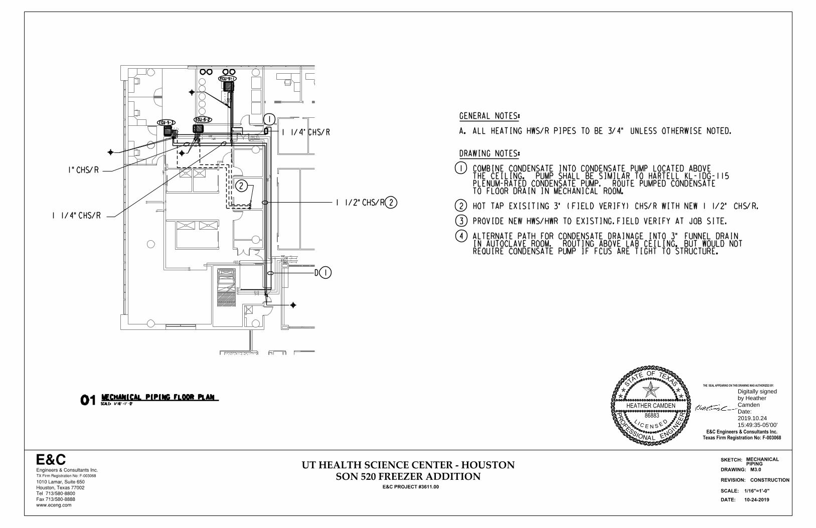
FEC3
FEC3
FEC1
HW
R
HW
S
HWRHWS
HW
S
HW
R
HWSHWR
CHSCHR
E&CEngineers & Consultants Inc.
1010 Lamar, Suite 650
Houston, Texas 77002
Tel 713/580-8800
Fax 713/580-8888
www.eceng.com
TX Firm Registration No: F-003068
UT HEALTH SCIENCE CENTER - HOUSTON
E&C PROJECT #3611.00
SON 520 FREEZER ADDITION
SKETCH:
DRAWING:
DATE:
REVISION:
10-24-2019
SCALE:
CONSTRUCTION
01 SCALE: 1/16"=1'-0"
1/16"=1'-0"
M3.0
D
MECHANICAL PIPING FLOOR PLAN
1
PIPINGMECHANICAL
FCU-5-1
FCU-5-2FCU-5-3
2
1"CHS/R
1 1/4"CHS/R
1 1/2"CHS/R
1 1/4"CHS/R
2
1
REQUIRE CONDENSATE PUMP IF FCUS ARE TIGHT TO STRUCTURE. IN AUTOCLAVE ROOM. ROUTING ABOVE LAB CEILING, BUT WOULD NOT4 ALTERNATE PATH FOR CONDENSATE DRAINAGE INTO 3" FUNNEL DRAIN
3 PROVIDE NEW HWS/HWR TO EXISTING.FIELD VERIFY AT JOB SITE.
2 HOT TAP EXISITING 3" (FIELD VERIFY) CHS/R WITH NEW 1 1/2" CHS/R.
TO FLOOR DRAIN IN MECHANICAL ROOM. PLENUM-RATED CONDENSATE PUMP. ROUTE PUMPED CONDENSATE THE CEILING. PUMP SHALL BE SIMILAR TO HARTELL KL-1DG-1151 COMBINE CONDENSATE INTO CONDENSATE PUMP LOCATED ABOVE
DRAWING NOTES:
A. ALL HEATING HWS/R PIPES TO BE 3/4" UNLESS OTHERWISE NOTED.
GENERAL NOTES:
LIC E N
ESD
86883
HEATHER CAMDEN
THE SEAL APPEARING ON THIS DRAWING WAS AUTHORIZED BY:
E&C Engineers & Consultants Inc.Texas Firm Registration No: F-003068
STATE OF TEXA
S
PROF
ESSIONAL EN
GIN
EER
Digitally signed by Heather CamdenDate: 2019.10.24 15:49:35-05'00'

E&CEngineers & Consultants Inc.
1010 Lamar, Suite 650
Houston, Texas 77002
Tel 713/580-8800
Fax 713/580-8888
www.eceng.com
TX Firm Registration No: F-003068
UT HEALTH SCIENCE CENTER - HOUSTON
E&C PROJECT #3611.00
SON 520 FREEZER ADDITION
SKETCH:
DRAWING:
DATE:
REVISION:
10-24-2019
SCALE:
CONSTRUCTION
NO SCALE
M4.0
MECH. DETAILS
NOT TO SCALE
~
~ =45
TYPICAL ROUND/OVAL
DUCT FITTINGS
EXPANDED DUCT TAPEXPANDED DUCT TAP
Q=45!
R=1.5 D
45! ELBOW
Y-BRANCH
EQUAL SPLIT TEE
D
(SADDLE CONICAL
LATERAL TAP)
(FOR VELOCITY
ABOVE 1500 FPM)
(CONTOURED LOLOSS
TEE TAP)
(FOR VELOCITY
ABOVE 1500 FPM)
(FOR UP STREAM VELOCITY
ABOVE 2500 FPM)
(Y-2PLUS 45! ELBOWS
MAX. C=.22)
DETAIL OF TURNING VANE
2" O.C.
45!
45!
2"
MITERED ELBOWR
RADUIS ELBOW
D
R=1.5 D
R=1.5 x W
R
TYPICAL DUCT FITTINGS
W
RADIUS ELBOW SQUARE ELBOW DETAIL OF TURNING VANE
NOT TO SCALE
EXPANDED DUCT TAP SPLIT DUCT TAP
EQUAL SPLIT SQUARE TEE UNEQUAL SPLIT SQUARE TEE
Q=45!
W
L
TYP. SPLITTER
DAMPER, WHERE
SHOWN ON DWGS.BALL JOINT
BRACKET (TYP)
TYP. MANUAL
VOLUME DAMPER,
WHERE SHOWN
ON DRAWINGS.
2" O.C.
45!
45!
2"
L=W/4,4" MIN
NOT TO SCALE
TYPICAL BALANCING
DAMPER OPERATORS
'L' HANDLE
BALL JOINT
BRACKET
DUCT
CONTROL ROD
SPLITTER
DAMPER
BLADE
BALL JOINT
BRACKET
TYPICAL SPLITTER DAMPER CONTROL ROD
CONCEALED REGULATOR
(NOTE 2)
EXTENDED DAMPER
ROD (NOTE 2)
UNIVERSAL JOINT
(NOTE 2)
DAMPER REGULATOR
(NOTE 1)
RAISED INSULATION
BASE
DUCT
NOTES:
1. LEVER TYPE LOCKING QUADRANT FOR
CONCEALED DAMPERS IN ACCESSIBLE
AND IN INACCESSIBLE LOCATIONS
WHERE ACCESS DOORS ARE PROVIDED.
2. EXTENDED DAMPER ROD WITH UNIVERSAL
JOINT(S) OR ANGLE GEARBOX TO FLUSH
MOUNTED CONCEALED REGULATOR WHERE
NOTED FOR CONCEALED, NON-ACCESSIBLE
DAMPERS, UNLESS NOTED OTHERWISE.
LOCKING NUT TYPE REGULATOR WITHOUT
LEVER FOR EXPOSED DUCTWORK IN
OCCUPIED SPACES.
SINGLE BLADE OR
OPPOSED BLADE
DAMPER
DUCT
LOCATIONS, IN MECHANICAL SPACES
TYPICAL DAMPER CONTROL REGULATOR
DUCTWRAP
LINER
03
(TYPICAL)
HANGERS
NOT TO SCALE
BY THERMAFLEX
ELBOW SUPPORT
MODEL FLEXFLOW
TYPICAL ELBOW
CONNECTION
6'
MA
X.
6"
MI
N.
6'MAX.
2'MIN.
6'
MA
X.
6"
MI
N.
6'MAX.
2'MIN.
HARD ELBOW
90 DEGREE
AS NOTED ON DRAWINGS
NECK SIZE TO AIR DEVICE
SCHEDULE AIR DEVICE,
1. HARD OR FLEXFLOW ELBOW IS THE CONTRACTOR'S OPTION.
3. MAXIUM 10'-0" RUN TOTAL
WHERE SPACE WILL NOT ALLOW, DETAIL XXX SHALL BE UTILIZED.
2. WHERE SPACE CONSTRAINTS ALLOW, THIS DETAIL SHALL BE UTILIZED.
NOTE:
OR
02
010405 NOT TO SCALE
SPRING LOCK
TYPICAL AIR DEVICES
AS SCHEDULED
RE: DETAILS
SPECIFIED DUCT WITH LINER
ON DUCTWORK AS SPECIFIED
SPIN-IN COLLAR WITH MANUAL
VOLUME DAMPER. ORIENT DAMPER
SHAFT PARALLEL TO DUCT AIR
FLOW. PROVIDE ACCESS DOOR IF
DAMPER IS LOCATED IN AN
INACCESSIBLE LOCATION.
INSULATED RIGID ROUND DUCT
EXTENSION AS REQUIRED
TYPICAL AIR DEVICE
FLEXIBLE CONNECTION
FLEXIBLE DUCT (8' MAXIMUM)
SUPPORT FLEXIBLE DUCT
RUNS OVER 36" ON 36"
CENTERS.
SEAL FLEXIBLE DUCT
LINER WITH DRAWBAND
AND SEAL VAPOR
BARRIER WITH DUCT
TAPE (TYP)
NOT TO SCALE
WALL
SPECIFIED DUCT, SIZE AS SHOWN
ON DRAWING
1" MINIMUM CLEAR ON ALL SIDES
FRAMED WALL OPENING 2" LARGER
THAN DUCT OUTSIDE DIMENSIONS.
TYPICAL SHEET METAL
DUCT THRU WALL
NOTE:
DRYWALL, METAL STUDS OR ANY OTHER RIGID MATERIAL
MUST NOT TOUCH THE DUCT.
1" FIBERGLASS INSULATION TIGHTLY
PACKED AROUND DUCT ON ALL FOUR
(4) SIDES AND FREE OF VOIDS.
NOT TO SCALE
TYPICAL PIPE AND DUCT
SUPPORT ATTACHMENT
LEVEL HANGER
SPACER TO
FLOOR
ANGLE CLIP
PIPE HANGER ROD
CONCRETE STRUCTURE
DUCT HANGER
RE: SPECIFICATION
RE: SPECIFICATION
08
07
WALL
DUCT SUPPORT
NOT TO SCALE
TYPICAL LOW/HIGH EXHAUST06
BUG SCREENCOVER THE OPENING WITHSTOP DUCT 6" ABOVE FLOOR
DUCT TIGHT TO STRUCTURE
AFTER ELBOW
DIRECTLY
HIGH TAP
LIC E N
ESD
86883
HEATHER CAMDEN
THE SEAL APPEARING ON THIS DRAWING WAS AUTHORIZED BY:
E&C Engineers & Consultants Inc.Texas Firm Registration No: F-003068
STATE OF TEXA
S
PROF
ESSIONAL EN
GIN
EER
Digitally signed by Heather CamdenDate: 2019.10.24 15:49:35-05'00'

E&CEngineers & Consultants Inc.
1010 Lamar, Suite 650
Houston, Texas 77002
Tel 713/580-8800
Fax 713/580-8888
www.eceng.com
TX Firm Registration No: F-003068
UT HEALTH SCIENCE CENTER - HOUSTON
E&C PROJECT #3611.00
SON 520 FREEZER ADDITION
SKETCH:
DRAWING:
DATE:
REVISION:
10-24-2019
SCALE:
CONSTRUCTION
NO SCALE
M5.0
MECH. DETAILS
12"
MA
X
1|2"
STIFFEN AS
REQUIRED
TYPICAL ROUND
DUCT DAMPER
REGULATOR
RE: TYPICAL
DETAIL
CONTINUOUS ROD ON ALL DUCT
OVER 12" DIA AND ON ALL DUCT
2" WG AND ABOVE
SINGLE BLADE BALANCING DAMPERS MAY BE USED IN ROUND DUCT AND
IN RECTANGULAR DUCT UP TO A MAXIMUM DUCT SIZE OF 12" H x 48" W
22 GA BLADEDUCT
3|8" REGULATOR
RE: TYP DETAIL
1|8" CLEARANCE ALL
AROUND UP TO 18"
12"
MA
X
TYPICAL RECTANGULAR DUCT DAMPER
DUCT
12"
MA
X
1|2" REGULATOR
RE: TYP DETAIL
1|8" CLEARANCE ALL
AROUND UP TO 19"-48"
3|8" CDS ROD 1|2" CDS ROD
16 GA BLADE
ROD END BEARING. PROVIDE OUTSIDE END BEARING
AT PRESSURE UP TO 2"WG. PROVIDE INSIDE ROD
BEARING AT PRESSURES 3"WG AND ABOVE (TYP)
ELEVATION OF TYPICAL
RECTANGULAR DUCT DAMPER
NOT TO SCALE
TYPICAL DUCT MOUNTED SINGLE
BLADE BALANCING DAMPERS01 NOT TO SCALE
TYPICAL DUCT MOUNTED
AIR DEVICE
AIRFLOW
SPECIFIED DUCT WITH LINER
OR DUCTWRAP AS SPECIFIED
CONTROL ROD TO
LIMIT THIS
DIMENSION TO
20% OF DUCT
WIDTH
AIR EXTRACTOR, IF
SPECIFIED. PROVIDE
ACCESSIBLE CONTROL
IN AIR OUTLET
COLLAR
INSULATED DUCT TAP
HEMMED DUCT EDGE
ALL SIDES
OPPOSED BLADE DAMPER,
IF SCHEDULED
SCHEDULED AIR DEVICE.
ACTUAL AIR DEVICE SCHEDULED
MAY VARY FROM AIR DEVICE
SHOWN.
SUPPLY
RETURN
STOP VALVE
AIR FLOW
NOT TO SCALE TYPICAL FAN COIL
FAN COIL UNIT
BALANCING/STOP VALVE
1. INSULATE ALL PIPING, VALVES, FITTINGS AND ACCESSORIES.
RE: SPECIFICATIONS.
NOTES:
MANUAL AIR VENT (TYPICAL)
COIL INLET
(DISCHARGE FACE)
2. INSTALL TEST PORTS IN EASILY ACCESSIBLE LOCATIONS WITH
MINIMUM OF 12" CLEARANCE ABOVE AND IN FRONT OF PORTS.
UNIT COIL PIPING
ECCENTRIC REDUCER (TYP)
PRESSURE AND TEMPERATURE
TEST PORT (TYP)
UNION (TYP)
TWO-WAY TEMPERATURE
CONTROL VALVE
05
NOT TO SCALE
EXHAUST CONTROL VALVE
TYPICAL VARIABLE VOLUME
SIDE AND EACH END
FOUR HANGERS, ONE ON EACH
FOR FLANGE CONNECTION,
HANGER AT EACH END
VALVE CONTROLS
EMSURE ACCESS TO
EXHAUST CONTROL VALVE,
CONTROLLER
AND SCHEDULES
MECH. FLOOR PLANS
VALVE DIAMETER, RE:
DUCT DIFFERS FROM
TRANSITION TO WHERE
AS SIZED ON FLOOR PLAN
EXISTING OR NEW DUCT
STAINLESS STEEL
04
PRESSURE
LOW
PRESSURE
HIGH/MEDIUM
02
03NOT TO SCALE
RETURN AIR BOOT DETAIL
XX2•" 2•"
VA
RI
ES
3"2"
2"
SE
E
DR
AWIN
GS
ABOVE
RA OPENING
SEE DRAWINGS
THE OPENINGS
FOR LOCATION OF
ELEVATION
PLAN
VARIES (RE; DRAWINGS NOTES)
3"
NO
TE
S)
(R
E:
DR
AWI
NG
10"
OR 12" STRUCT.
(MIN.) FROM
INSTALL 10"
X = DUCT HEIGHTLIC E N
ESD
86883
HEATHER CAMDEN
THE SEAL APPEARING ON THIS DRAWING WAS AUTHORIZED BY:
E&C Engineers & Consultants Inc.Texas Firm Registration No: F-003068
STATE OF TEXA
S
PROF
ESSIONAL EN
GIN
EER
Digitally signed by Heather CamdenDate: 2019.10.24 15:49:35-05'00'

E&CEngineers & Consultants Inc.
1010 Lamar, Suite 650
Houston, Texas 77002
Tel 713/580-8800
Fax 713/580-8888
www.eceng.com
TX Firm Registration No: F-003068
UT HEALTH SCIENCE CENTER - HOUSTON
E&C PROJECT #3611.00
SON 520 FREEZER ADDITION
SKETCH:
DRAWING:
DATE:
REVISION:
10-24-2019
SCALE:
CONSTRUCTION
NO SCALE
M6.0
MECH. SCHEDULES
FAN COIL UNIT SCHEDULEGENERAL INFORMATION MOTOR COOLING COIL HEATING COIL
UNIT NO. LOCATION SERVICE COOLING TYPECFM
TOTAL
CFM
MIN. O.A.
IN W.G.
EXT. S.P.RPM HP BHP
HZ
@ 60
VOLTS
PHCFM
DESIGNENTERING AIR LEAVING AIR
MBH
TOTALGPM
ROWS
NO. OF
SERIES
FINMAX. P.D.
DB F
AIR
ENT.
DB F
AIR
LVG.
EWT (F)LWT (F)ROWS
NO
GPM
MAXMANUFACTURER MODEL/SERIES NOTES
DB F WB F DB F WB FIN.
EXT. AIR
FCU-5-1 5TH FLOOR FREEZER ROOM CHILLED WATER 1100 250 0.5 1268 3/4 0.49 208 1 1100 75 62 51.5 50.7 32.7 9.6 6 -- 0.32 65.9 78.0 120.0 110.0 1.0 3.0 MAGICAIRE HBB 12 HORIZONTAL (1)(2)
FCU-5-2 5TH FLOOR OFFICE SPACE EXTERIOR CHILLED WATER 700 40 0.5 1134 1/2 0.20 120 1 700 75 62 51.4 50.6 20.7 7.2 6 -- 0.32 69.0 81.0 120.0 110.0 1.0 2.0 MAGICAIRE HBB 08 HORIZONTAL (1)(2)
FCU-5-3 5TH FLOOR OFFICE SPACE INTERIOR CHILLED WATER 500 65 0.5 1185 1/2 0.26 120 1 500 75 62 52.7 52.3 14.9 4.7 6 -- 0.32 69.0 75.0 120.0 110.0 1.0 1.5 MAGICAIRE HBB 06 HORIZONTAL (1)(2)
NOTES:
1. UNIT PROVIDED WITH FLOAT SWITCH AT DRAIN PAN.
2. UNIT PROVIDED WITH UNIT MOUNTED DISCONNECT.
3. PROVIDE UNIT WITH ECM MOTOR.
AIR DISTRIBUTION DEVICE SCHEDULE
NECK
UNIT NO. SERVICE TYPE FINISHIN.
DIAMETERSQUARE IN. FACE IN. SQ.
TURER
MANUFAC
RIES
MODEL/SEREMARKS
A SUPPLY PLAQUE WHITE SEE PLAN - 24X24 TITUS OMNI LAY-IN
B RETURN PLAQUE WHITE SEE PLAN SEE PLAN 24X24 TITUS OMNI LAY-IN
C RETURN/EXHAUST SIDEWALL WHITE - SEE PLAN SEE PLAN TITUS 300 SIDEWALL
D SUPPLY PLAQUE WHITE SEE PLAN - 24X24 TITUS R-OMNI LAY-IN
NOTES:
1. COORDINATE DIFFUSER COLOR/FINISH WITH ARCHITECT.
CHS
CHR
4
DT
1
AIR
RETURN
7
460/3/60
2
MOUNTED IN ROOM
ZONE THERMOSTAT
8
NOT TO SCALE
1 A/I X
2
3
4 A/0
5
6
7
8 A/I
A/0
MOTOR START/STOP D/0
ZONE THERMOSTAT
9
ITEMSIGNAL TYPE
CONTROLALARMDESCRIPTION
FILTER PRESS. DIFF. TRANSDUCER
10
D/ICURRENT SWITCH X
X
M
C
C
H
C
D/I X
A/I
A/I
DRAIN PAN FLOAT SWITCH
AIR
OUTSIDE2-WAY VALVE ACTUATOR CC
2-WAY VALVE ACTUATOR HC
HWS
HWR
T
CONTROL VALVE POSITION INDICATOR
FL 3
CONTROL VALVE POSITION INDICATOR
04COOLING AND HEATING FAN COIL UNIT - CONTROL DIAGRAM
56
9A/I XO2 SENSOR (FCU-5-1 ONLY)
O2
10
HEAT: WATER HOT WITH UNIT COILFAN
controls. related and coil heating waterhot coil,cooling
water chilled fan, volume constant belt-drive, with unit coil fan zone single of consists unit ThisGeneral:A.
. switchcurrent a through BCAS the at indicated be shall fansupply
unit the of Status started. manually be shall fan air supply the position, hand the in is switch H-O-A theWhen
BCAS. the through stopped and started be shall fan supply unit the position, auto the in is switch H-O-Athe
When starter. fan the on switch H-O-A a by controlled be shall fan supply unit The Control: FanBelt-driveB.
and heating water control valve shall close to the coil.
water valve shall remain closed whenever the heating valve is open. Upon unit shutdown, the chilled water
panel monitoring the unit shall provide setpoint adjustment over user programmable range. The chilled
and cooling to 74 degrees (operator adjustable). A setpoint adjustment potentiometer in the HVAC control
required maintain the adjustable space temperature setpoint with deadband typically heating to 70 degrees
2-way chilled water coil control valve and modulate a normally closed 2-way hot water coil control valve as
served by the unit shall provide an input to the unit DDC controller which shall modulate a normally closed
C. Chilled Water Cooling Coil/Hot Water Heating Coil: An analog temperature sensor located in the area
pan shall shut down the fan coil unit and alarm to the BAS.
Alarm shall be both local and at the BAS. Floatswitches located in the secondary drain
D. Safeties: An O2 sensor in the fcu-5-1 room shall be set to alarm on low oxygen levels (owner adjustable)
across the filter exceeds the filter manufacturers recommendations (owner adjustable).
bank shall provide an input to the DDC Panel which shall initiate a BCAS alarm when the pressure drop
E. Air Filters: A differential pressure transducer sensing the pressure differential across each air handling unit filter
LIC E N
ESD
86883
HEATHER CAMDEN
THE SEAL APPEARING ON THIS DRAWING WAS AUTHORIZED BY:
E&C Engineers & Consultants Inc.Texas Firm Registration No: F-003068
STATE OF TEXA
S
PROF
ESSIONAL EN
GIN
EER
Digitally signed by Heather CamdenDate: 2019.10.24 15:49:35-05'00'

FEC3
J
A
A
5EL1-25
J
S
AV
E&CEngineers & Consultants Inc.
1010 Lamar, Suite 650
Houston, Texas 77002
Tel 713/580-8800
Fax 713/580-8888
www.eceng.com
TX Firm Registration No: F-003068
UT HEALTH SCIENCE CENTER - HOUSTON
E&C PROJECT #3611.00
SON 520 FREEZER ADDITION
SKETCH:
DRAWING:
DATE:
REVISION:
10-24-2019
SCALE:
CONSTRUCTION
SCALE: 1/8"=1'-0"01 ELECTRICAL DEMOLITION FLOOR PLAN
E1.0
1/8"=1'-0"
X
X
X
X
XX
X
X
X XX
PLANELEC. LIGHTING
2
1
1
3 EXISTING FIRE ALARM STROBE TO BE RELOCATED.
2 EXISTING SWITCH TO BE REMOVED. PATCH WALL.
RE: E2.0 LIGHTING RENOVATION PLAN FOR NEW LOCATION.1 EXISITNG 1X4 CHAIN HUNG TO BE RELOCATED,
DRAWING NOTES:
3
X
X
LIC E N
ESD
86883
HEATHER CAMDEN
THE SEAL APPEARING ON THIS DRAWING WAS AUTHORIZED BY:
E&C Engineers & Consultants Inc.Texas Firm Registration No: F-003068
STATE OF TEXA
S
PROF
ESSIONAL EN
GIN
EER
Digitally signed by Heather CamdenDate: 2019.10.24 15:49:35-05'00'

FEC3
RF1
PF12
SF9
RF7 RF7RF7
RF8 RF8
SF5
bPF12b
a
E&CEngineers & Consultants Inc.
1010 Lamar, Suite 650
Houston, Texas 77002
Tel 713/580-8800
Fax 713/580-8888
www.eceng.com
TX Firm Registration No: F-003068
UT HEALTH SCIENCE CENTER - HOUSTON
E&C PROJECT #3611.00
SON 520 FREEZER ADDITION
SKETCH:
DRAWING:
DATE:
REVISION:
10-24-2019
SCALE:
CONSTRUCTION
HVAC
SHAFT
SHAFT
FEC3
CG CGCG CG
FEC3
FVC
FVCFVC
FEC1FEC1
DN
UP
UPDN
OPEN OPEN
DN
UP
FE2 FE2
FEC3
existing
existing
existing
existing
existing
existing
existing
existing
existing
existing
new
new OFFICEOFFICE OFFICE
OFFICE
OFFICE
CONFERENCE
SCALE: 1/8"=1'-0"01
E2.0
S
SS
S
S
AND POWERELEC LIGHTING
2
2
2
5EL1-25
2
1
1
9
3
J
J
J
8 (TYP.)
S
S
MM
M
IN THE ELECTRICAL ROOM
ALL PANELS LOCATED
5
7 (TYP.)
(TYP.)
6
(TYP.)
10
11 (TYP.)
12
(TYP.)
1/8"=1'-0"
ELECTRICAL RENOVATION LIGHTING PLAN
AV
10
13
13 PROVIDE NEW EXIT SIGN TO MATCH BUILDING STANDARD. CONNECT COMPONENTS IN ROOM PER MANUFACTURERS INSTRUCTIONS. CONTROLS IN THIS ROOM. EQUAL TO WATTSTOPPER #LMRJ. 12 NEW LOW VOLTAGE CONTROL CABLE TO CONNECT LIGHTING
#LMSW-101.11 NEW DIGITAL SINGLE ZONE SWITCH EQUAL TO WATTSTOPPER
INSTRUCTION. WATTSTOPPER # LMRC-101.INSTALL PER MANUFACTUERS 10 NEW DIGITAL SINGLE RELAY ROOM CONTROLLER EQUAL TO
INSTRUCTIONS. WATTSTOPPER # LMDC-100.INSTALL PER MANUFACTURERS. 9 NEW DIGITAL DUAL TECHNOLOGY MOTION SENSOR EQUAL TO
WHITE, EQUAL TO WATTSTOPPER # DSW-301-W.8 NEW LINE VOLTAGE DUAL TECHNOLOGY MOTION SENSOR,120/277V,
7 EXISTING 2X4 FROM ATTIC STOCK TYPE RF8,TYPICAL.
SERVING LIGHTING IN THE HALLWAY.6 CIRCUIT LIGHTING TO PANEL 5LC-3. EXISTING CIRCUIT IS
REMAIN AND SERVE RELOCATED LIGHTING AS SHOWN.5 EXISTING CIRCUIT SERVING LIGHTING IN THIS AREA TO
FIRE ALARM AS REQUIRED.4 NEW FIRE ALARM VISUAL SIGNAL. TIE INTO EXISTING
3 RELOCATE FIRE ALARM DEVICE FOR PROPER VISABILITY.
2 NEW OWNER FURNISHED CHAIN HUNG LIGHTS.
LOCATION.RE-HANG FIXTURE AND CIRCUIT AS SHOWN.1 EXISTING 1X4,CHAIN HUNG,TO BE RELOCATED TO THIS
DRAWING NOTES:
ABBERVIATIONS.A. RE: ME0.00 FOR MORE GENERAL NOTES, SYMBOLS AND
GENERAL NOTES:
9
(TYP.)
1211
4
PP
M
M
M
M
PP
AV
LIC E N
ESD
86883
HEATHER CAMDEN
THE SEAL APPEARING ON THIS DRAWING WAS AUTHORIZED BY:
E&C Engineers & Consultants Inc.Texas Firm Registration No: F-003068
STATE OF TEXA
S
PROF
ESSIONAL EN
GIN
EER
Digitally signed by Heather CamdenDate: 2019.10.24 15:49:35-05'00'

FEC3
RF1
PF12
SF9
RF7 RF7RF7
RF8 RF8
SF5
bPF12b
a
E&CEngineers & Consultants Inc.
1010 Lamar, Suite 650
Houston, Texas 77002
Tel 713/580-8800
Fax 713/580-8888
www.eceng.com
TX Firm Registration No: F-003068
UT HEALTH SCIENCE CENTER - HOUSTON
E&C PROJECT #3611.00
SON 520 FREEZER ADDITION
SKETCH:
DRAWING:
DATE:
REVISION:
10-24-2019
SCALE:
CONSTRUCTION
HVAC
SHAFT
SHAFT
FEC3
CG CGCG CG
FEC3
FVC
FVCFVC
FEC1FEC1
DN
UP
UPDN
OPEN OPEN
DN
UP
FE2 FE2
FEC3
existing
existing
existing
existing
existing
existing
existing
existing
existing
existing
new
new OFFICEOFFICE OFFICE
OFFICE
OFFICE
CONFERENCE
SCALE: 1/8"=1'-0"01 ELECTRICAL RENOVATION POWER PLAN
E3.0
IN THE ELECTRICAL ROOM
ALL PANELS LOCATED
1/8"=1'-0"
FCU-5-1
FCU-5-2
FCU-5-3
1
(TYP.)
6
6
5
2
2
2
3
4
POWER PLANELECTRICAL
REQUIRED. DISCONNECT AT PUMP AND MAKE CONNETION TO UNIT AS 7 PROVIDE 20A/1P/120V MOTOR RATED TOGGLE SWITCH
REQUIRED. DISCONNECT AT FCU AND MAKE CONNETION TO UNIT AS PROVIDE 20A/1P/120V MOTOR RATED TOGGLE SWITCH 6 CIRCUIT TO SPARE 20/1 BREAKER IN PANEL 5LA,2#12,#12G,3/4"C
CONNETION TO UNIT AS REQUIRED. PROVIDE 30A/2P/15AF/NEMA 1 DISCONNECT AT FCU AND MAKE NEW BREAKER SHALL MATCH EXISTING PANEL BRACING.5 CIRCUIT TO NEW 15/2 BREAKER IN PANEL 5LE,2#12,#12G, 3/4"C,
PANEL 5LA,6#12,#12G, 3/4"C.4 CIRCUIT TO(3 )THREE SPARE 20A,1P,120V CIRCUIT BREAKERS IN
PANEL 5LA,4#12,#12G, 3/4"C.3 CIRCUIT TO(2 )TWO SPARE 20A,1P,120V CIRCUIT BREAKERS IN
5LA,2#12,#12G, 3/4"C.2 CIRCUIT TO SPARE 20A,1P,120V CIRCUIT BREAKER IN PANEL
1 EXISTING POWER TO REMAIN.
DRAWING NOTES:
ABBERVIATIONS.A. RE: ME0.00 FOR MORE GENERAL NOTES, SYMBOLS AND
GENERAL NOTES:
7
LIC E N
ESD
86883
HEATHER CAMDEN
THE SEAL APPEARING ON THIS DRAWING WAS AUTHORIZED BY:
E&C Engineers & Consultants Inc.Texas Firm Registration No: F-003068
STATE OF TEXA
S
PROF
ESSIONAL EN
GIN
EER
Digitally signed by Heather CamdenDate: 2019.10.24 15:49:35-05'00'