fire behavior of simulated low voltage intumescent cables
TRANSCRIPT

HAL Id: hal-01697376https://hal.archives-ouvertes.fr/hal-01697376
Submitted on 31 Jan 2018
HAL is a multi-disciplinary open accessarchive for the deposit and dissemination of sci-entific research documents, whether they are pub-lished or not. The documents may come fromteaching and research institutions in France orabroad, or from public or private research centers.
L’archive ouverte pluridisciplinaire HAL, estdestinée au dépôt et à la diffusion de documentsscientifiques de niveau recherche, publiés ou non,émanant des établissements d’enseignement et derecherche français ou étrangers, des laboratoirespublics ou privés.
Fire behavior of simulated low voltage intumescentcables with and without electric current
Johan Sarazin, Pierre Bachelet, Serge Bourbigot
To cite this version:Johan Sarazin, Pierre Bachelet, Serge Bourbigot. Fire behavior of simulated low voltage intumescentcables with and without electric current. Journal of Fire Sciences, SAGE Publications, 2017, 35 (3),pp.179 - 194. �10.1177/0734904117698843�. �hal-01697376�
1
DOI: 10.1177/0734904117698843 – Journal: Journal of Fire Sciences – Post-print
Fire behavior of simulated low voltage intumescent cables with and without
electric current
Journal of Fire Sciences
Volume: 35 issue: 3, page(s): 179-194
Authors:
Johan Sarazin, Pierre Bachelet, Serge Bourbigot
R2Fire Group/UMET–UMR CNRS 8207, Ecole Nationale Supérieure de Chimie de Lille
(ENSCL), Villeneuve d’Ascq, France
Corresponding Author: Serge Bourbigot, R2Fire Group/UMET–UMR CNRS 8207, Ecole
Nationale Supérieure de Chimie de Lille (ENSCL), Avenue Dimitri Mendeleïev–Bât. C7a, CS
90108, 59652 Villeneuve d’Ascq, France. Email: [email protected]
First published: 20/03/2017
DOI: 10.1177/0734904117698843
Abstract.
Many circumstances can lead to an electrical fire. It is then helpful to reproduce those
circumstances in laboratory conditions to duplicate fire scenarios in order to increase
knowledge and to develop safer and flame-retarded materials and electrical systems. Our
approach was to develop specific bench scale tests. The mass loss cone calorimeter coupled
with Fourier transform infrared was used to mimic a fire scenario on simulated low voltage
cable (flame-retarded polymer molded around copper wire) and to characterize the gas phase.
The electric current creates an additional heating condition (Joule effect) which can modify the
decomposition of the flammable material (e.g. the cable jacket made in thermoplastic), and so
its fire behavior in case of fire. It is the reason why we performed the experiments mimicking
different fire scenarios with and without electric current. Specific test was also developed to
investigate the flame spread and the delamination of the polymer around the wire. The bench
scale tests presented in this article were applied on intumescent polymers (ethylene-vinyl
acetate containing commercial intumescent additive). The results were discussed with a special
emphasis on the influence of electric current on the fire behavior.
Keywords
Cable, electric current, intumescence, EVA
Post-print

2
DOI: 10.1177/0734904117698843 – Journal: Journal of Fire Sciences – Post-print
Introduction
According to a recent NFPA report of 2013,1 an estimated 47,700 home structure fires reported
to US fire departments in 2011 involved electrical failure or malfunction as a factor contributing
to ignition. These fires resulted in 418 civilian deaths, 1570 civilian injuries, and US$1.4 billion
in direct property damage. Non-home electrical fires in 2011 were estimated at 16,400, with
associated losses of 13 civilian deaths, 243 civilian injuries, and US$501 million in direct
property damage. The most inclusive and direct interpretation of “electrical fire” is a fire
involving some type of electrical failure or malfunction. Any equipment powered by electricity
can have such a failure. Polymeric materials are very often involved in such fires and so it is
paramount to investigate their fire behavior in those conditions. Among them, electrical cables
are potential combustible materials which can spread fire along cable trays.
The electrical cables are used in different fields, with different requirements and different
environments. Many circumstances can lead to the degradation of the insulation system of an
electrical cable. The insulation sheath to electrical cables can be ignited by an external source;
however, according to the power supply, the applied electric field, the composition of the
conductor and of the insulative material, different failures can occur such as a short-circuit,
heating, sparks, or electrical arcing.2,3
The short circuits can come from an unfortunate human action (punching of a cable), an
avalanche failure mechanism, or birth of electrical tree. The avalanche failure mechanism is
caused by an electron initially injected to the cathode. The electron is accelerated toward the
anode under the influence of an electric field and receives sufficient energy to release another
electron by ionization. If the mechanism continues, the local concentration of high energy
electron increases, creating a conductive road between the electrodes. The birth of electrical
tree is caused by an internal electrical discharge, locally destroying the material by forming
very fine channels. In short, medium, or long term, this mechanism will lead to electrical
breakdown that is a consequence of the formation of a conductive path.
Additional heating can be generated by the Joule effect, which can be due to a partial
disconnection, an overcurrent, or by a relaxation phenomenon under alternative current.
Electrical arcs can come from a reduction of the dielectric properties of the sheathing, the
presence of moisture and/or a conductive dust deposit or of an overvoltage. This additional
heating of the conductor caused by Joule effect can modify the fire behavior of the material,
but it is not taken into account in conventional tests (ISO5660, EN50399). Hence, it makes
sense to reproduce this additional heating in laboratory conditions to investigate the
modification of the fire behavior of the formulation used for insulation sheath. It should increase
our understanding and should permit to develop safer and flame-retarded materials for electrical
systems.
In recent years, concerns have been widely expressed about the inherent toxicity of halogenated
flame retardants used for decades in electrical and electronics applications. If these formulations
limit the spread of fire, they significantly hinder the rescuers because of the opacity of smoke
released and cause extensive damage due to the presence of corrosive vapors.4 These factors
lead to an increasing demand of non-halogenated flame retardants in electrical and electronics
applications. Thus, phosphorus derivatives are more and more used in polymeric materials
thanks to their high efficiency and their reasonable loading. In addition, they are widely used
in intumescent systems.
3
DOI: 10.1177/0734904117698843 – Journal: Journal of Fire Sciences – Post-print
In this article, a small scale test developed in our lab5 and a mass loss calorimeter (MLC)
coupled with a Fourier transform infrared (FTIR) spectrometer were used for the evaluation
and characterization of cables. In order to test our own materials developed in the laboratory,
an experimental protocol to prepare “homemade cable” was set up. It permits to mimic the fire
behavior of real low voltage cables. The simulated cables are constituted of an external cable
jacket composed of intumescent ethylene-vinyl acetate (EVA) copolymer molded around a
copper wire.
The bench scale test results are presented in the first section of the article. In the second section,
simulated cables are evaluated according to the above test. The results are presented and
discussed with a special emphasis on the influence of electric current on the fire behavior.
Experimental: materials and bench scale test
Materials
EVA copolymer containing 28 wt% of vinyl acetate (EVA) was supplied by Arkema. Exolit
AP 760 is a non-halogenated flame retardant (FR) based on ammonium polyphosphate (APP);
Exolit AP760 in white powder was supplied by Clariant. When incorporated within a
polyolefin, this compound develops an intumescence phenomenon when a heat source is
applied.6 AP760 develops its effectiveness through phosphorus/nitrogen synergism. The
concept of intumescence relies upon the formation of an expanded carbonized layer on the
surface of the polymer during thermal degradation. This layer acts as an insulating barrier
limiting heat and mass transfers in the material.7 Two formulations were evaluated: (1) 20wt%
and (2) 30wt% of AP760 were incorporated into EVA. Those formulations were prepared using
a Brabender mixer 350/EH at a shear rate of 50 r/min and at 180°C. EVA was melted for 5 min,
afterward AP760 (20wt% or 30wt%) was incorporated in EVA and the formulation was mixed
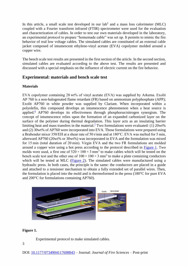
for 15 min (total duration of 20 min). Virgin EVA and the two FR formulations are molded
around a copper wire using a hot press according to the protocol described in Figure 1. Two
molds were used, a first one of 520 × 100 × 3 mm3 to make cables which will be tested on the
bench scale test and the other one of 100 × 100 × 3 mm3 to make a plate containing conductors
which will be tested at MLC (Figure 2). The simulated cables were manufactured using a
hydraulic press. In both cases, the principle is the same: the conductors are placed in a guide
and attached to a tensioner mechanism to obtain a fully extended set of parallel wires. Then,
the formulation is placed into the mold and is thermoformed in the press (180°C for pure EVA
and 200°C for formulations containing AP760).
Figure 1.
Experimental protocol to make simulated cables.

4
DOI: 10.1177/0734904117698843 – Journal: Journal of Fire Sciences – Post-print
Figure 2.
(a) Molded cables and (b) molded plate containing wires for MLC
experiments.
Mass loss cone coupled with FTIR
MLC (Fire Testing Technology) coupled with FTIR Spectrometer were used to characterize the
gas phase of samples upon burning. The experiments were performed according to the
procedure defined in ASTM E 906 (except FTIR, which is not included in the standard). The
equipment is identical to that used in oxygen consumption cone calorimetry (ASTM E-1354-
90), except that a thermopile in the chimney is used to obtain heat release rate (HRR) rather
than employing the oxygen consumption principle. Our procedure involved exposing plates in
horizontal orientation. Samples were placed on a ceramic backing board at a distance of 25 mm
from cone base. The external heat flux was of 35 kW/m2 and the experiments were performed
with piloted ignition and by submitting or not the sample to an electric current of 32 A. MLC
was used to determine the following main fire properties: HRR as a function of time, peak of
heat release rate (pHRR), time to ignition (TTI), and total heat release (THR). When measured
at 35 kW/m2, HRR, THR, and TTI values are reproducible to within ±10%. Experiments were
performed in triplicate to ensure repeatability of results. To investigate the gases released during
MLC experiment, MLC was connected to a Fourier transform infrared spectrometer (MLC-
FTIR).
Referring to previous work, gas phase FTIR spectroscopy has the potential to measure almost
all volatiles on a continuous basis during fire.8,9 The calibrated FTIR spectrometer used is from
Thermo Scientific™ (Antaris™ industrial gas system (IGS) equipped with a gas cell with an
optical pathway of 2 m long). Temperature and pressure must be taken into account in order to
obtain accurate and repeatable results. Numerous studies report the influence of temperature
and pressure on infrared absorption spectra.9 Here, the gas cell is maintained at 185°C and the
pressure inside the cell is set to 652 torr. Gas picking pistol and transfer line were provided by
M&C® Tech Group. The transfer line between MLC and FTIR is 2 m long and was heated at a
constant temperature of 180°C to avoid condensation in the transfer line. It has been shown that
the optimum set temperature for this kind of sampling and analysis is 180°C.10 Furthermore,
this temperature is less than the gas cell temperature to avoid condensation in the gas cell. To
get constant transfer line temperature, two temperature controllers were installed. Before
analyzing the gases by FTIR, soot particles were filtered off by two different heated filters (2
and 0.1 µm). Filters consist of glass fibers and ceramic, respectively. The gases are analyzed
online quantitatively and qualitatively with OMNIC software. The methodology of
quantification has been developed in the laboratory, and the quantification is then performed
using TQ Analyst software. Spectra have to be recorded at different concentrations of specific

5
DOI: 10.1177/0734904117698843 – Journal: Journal of Fire Sciences – Post-print
gases with the same conditions such as a cell temperature of 185°C, a pressure of 652 torr, an
optical path length of 2 m, and the spectral range from 650 to 4500 cm−1. Then the area under
the peaks of characterized absorbance bands is linked with the concentration of release gases.
For it, representative spectral region has been chosen for each gas to minimize interferences
with other gases to create a method, and representative regions in the spectra of the selected gas
have to be chosen and interactions with other gases have to be taken into account. Using MLC-
FTIR, the following gases can be quantified: water, carbon monoxide, carbon dioxide, acetic
acid, methane, and ethane. Quantification is reproducible within ±10%. MLC-FTIR
experiments were performed twice to check the repeatability of the obtained results. The
calibration was done by Thermo Scientific using the Fire Science Method and Calibration to
analyze toxic gases in the combustion of building materials according to the standard ISO
19702:2006. The method can be used with cone calorimeters, smoke boxes, or ambient
sampling of combustion experiments.
Flame spread test
All the existing standardized test measure flame spread of bundles of cable after ignition by a
burner. The cables can be disposed in horizontal or vertical positions and are tested power
down. Based on this, a small scale test was developed to study the fire behavior of a simulated
cable with the possibility to work under voltage. The purpose is to investigate the influence of
the electric current on the flame spread. Before developing a flame spread test, it is necessary
to determine all possible scenarios involving an electrical cable in nominal operation or not. In
the study, the conductor section used is 1.5 mm2. The first parameter to be examined is the
intensity that can cross a 1.5-mm2 cable. In nominal operation, a 1.5-mm2 conductor is traversed
by intensity as high as 16 A. On a circuit with a non-adapted protection, the section of the
conductor can be traversed by a higher current. In the worst cases, such as a bad connection or
facility with inadequate protection, a cable with 1.5 mm2 conductor cross section may be
connected to a system originally intended for a 6 mm2 (32 A). During a default, secondary
security organs are the main differential circuit breaker to limit the current driven by the
conductor. On some installations, the main GFCI (Ground Fault Circuit Interrupter) can reach
a 65-A breaking intensity, which can induce intensity in a 1.5-mm2 conductor up to four times
its rated current. The second parameter to be examined in a fire scenario is the ignition occurring
in relation to the electrical supply of the cable. The probable scenarios are ignition of the cable
before, simultaneously or after powering on. The ignition of the cable after powering on is
representative of fire safety cables. The ignition of the cable simultaneously with the electric
power-up may correspond to a scenario where the cable is responsible for the fire. A fault in
the electrical cable causes a sufficient dysfunction (significant heating, electric arc, and so on)
to ignite the insulating sheath. The ignition of a cable after powering on is the most common
case. There are two possibilities: the ignition of the insulation sheath is caused either by a
dysfunction or by an external fire source. According to a preliminary study, it has been decided
to perform the tests with a higher intensity than the nominal one as no significant differences in
terms of fire behavior were observed when working at lower or equal intensity.
Also, it was required for the different tests to apply the intensity before starting the test and to
wait for the stabilization of the system. In this work, a small scale test developed in the lab was
used for the evaluation of the fire spread along the cables, without and with electric current, in
horizontal or in vertical position. The description of the test is shown in Figure 3 with two
different setups in horizontal and vertical positions. The burner is a Bunsen burner fed by
200 mL/min of propane and delivering in those conditions a calibrated blue flame. The test is
performed in natural convection under a hood without any extraction, with and without electric

6
DOI: 10.1177/0734904117698843 – Journal: Journal of Fire Sciences – Post-print
current (current of 32 or 60 A). The measured parameters are as follows: flame spread rate
(electric current of 0 and 32 A) and time to delamination (electric current of 60 A).
Figure 3.
Description of the flame spread test in horizontal and vertical positions.
Results and discussion
Mass loss cone coupled with FTIR
The concept of intumescence involves the formation of an expanded char at the surface of the
polymer during thermal degradation. This char exhibits a multi-cellular structure and acts as an
insulating barrier limiting heat and mass transfer.11,12
The intumescent formulations were first evaluated by mass loss calorimetry on plates
containing or not copper wire to compare the conventional test (without conductor) with the
test with electric current (with conductor). Note that no significant effect was detected on the
material with and without copper wire (no electric current was applied) and it is not commented
in the following. An electric current of 32 A is applied to the plate containing copper wire to
evidence the effects of the current on the fire behavior of the formulations. In both cases, the
incorporation of AP760 in EVA reduces dramatically the pHRR. The formulation filled with
20wt% AP760 exhibits a pHRR decrease by 54% and that filled with 30wt% AP760 exhibits
77% decrease of the pHRR (Figure 4). THR is decreased by 23% for the formulation filled with
30wt% AP760 but no significant decrease is observed for the 20wt% loaded formulation.

7
DOI: 10.1177/0734904117698843 – Journal: Journal of Fire Sciences – Post-print
Figure 4.
HRR as a function of time of EVA and FR EVA with and without an electric
current of 32 A with forced ignition (external heat flux = 35 kW/m2).
When a current of 32 A is applied, two significant effects can be observed: diminution of the
TTI and of the THR. The TTIs of the EVA and FR formulations are shorter when the current is
on: TTI decreases from 60 to 41 s for neat EVA, from 43 to 20 s for 20wt% AP760 formulation,
and from 53 to 31 s for 30wt% AP760 formulation. This decrease can be explained by the fact
that when power is on, the material undergoes an additional heating due to the Joule effect
leading to a faster decomposition and therefore to a decrease of the TTI (assuming there is no
change of the thermo-optical properties of the sample). The other effect of the current is the
reduction of THR of neat EVA and of the two intumescent formulations. For the neat EVA,
THR is reduced from 93 to 72 MJ/m2; at 20wt% loading of AP760 in EVA, THR is reduced
from 91 to 47 MJ/m2; and at 30wt% loading in EVA, THR is reduced from 71 to 40 MJ/m2. It
is an unexpected result (THR is decreased by about 45% for the intumescent materials) because
it was reasonable to assume that an additional heating should lead to a faster and more complete
decomposition of the materials. For the neat EVA, it is only decreased by 20% and so it is much
less than in the case of intumescent materials. It is easily explained by the fact that the quantity
of polymer is less because it contains the copper wire. For the intumescent materials, the less
quantity of polymer cannot explain the huge decrease of THR. It is then assumed that the
additional heating inside the materials permits to fasten the intumescent reactions and hence the
development of the char. The combustion of the material stops in shorter times and so THR is
decreased.
When comparing the evolution of the expansion of the carbon shield obtained by MLC, a
relatively low expansion of the carbonaceous layer is observed for the formulation containing
20wt% AP760 (Figure 5). For the formulation loaded at 30wt% of AP760, a much higher
expansion than that of the formulation containing 20%AP760 is observed for the scenario
without current. With current, the expansion is strongly reduced. We also note that the
conductor is outside the residue.

8
DOI: 10.1177/0734904117698843 – Journal: Journal of Fire Sciences – Post-print
Figure 5.
Residues after MLC experiments with forced ignition for the formulations
EVA/AP760 (external heat flux = 35 kW/m2).
Char’s morphology of the above residues is examined by optical microscopy (Figure
6). We can distinguish that the size of the cells depends on the scenario. For
formulation at 20wt% of AP760, the cells’ size is bigger and their number is less than
that observed for the formulation containing 30wt% of AP760 (Table 1). Regarding
the formulation containing 30wt% of AP760, smaller cells are observed for scenario
with current. Indeed, the faster intumescent reactions promotes bubbling and hence the
apparition of smaller cells. The morphology of the residue obtained for the scenario
AP760 20wt% with electric current is not shown here because we only observe a non-
expanded carbonaceous skin with the copper wire outside of the structure.

9
DOI: 10.1177/0734904117698843 – Journal: Journal of Fire Sciences – Post-print
Figure 6.
Char morphology observed after analysis of formulations EVA/AP760 with
MLC with forced ignition (external heat flux of 35 kW/m2).
To further investigate the effect of the electric current, the gas phase was examined to
characterize the decomposition products according to the MLC fire scenario. The
identification of the different gases released by the decomposition of EVA is consistent
with the work described in the literature13 (Figures 7 and 8). When applying a heat flux
of 35 kW/m2, the C=O stretching in the region around 1810–1790 cm−1 and OH
bending around 998 cm−1 corresponding to acetic acid (CH3COOH), water (H2O) with
broad bands around 3900–3500 cm−1, carbon dioxide (CO2) corresponding to the
absorption bands around 2357–2310 cm−1, carbon monoxide (CO) with absorption
bands around 2357–2310 cm−1, methane (CH4) with a peak around 3030–990 cm−1,
and ethylene (C2H4) with a peak around 995-985 cm−1 was observed. Methane and
ethylene come from the scission of the linear polyene formed after the deacetylation
of EVA.

10
DOI: 10.1177/0734904117698843 – Journal: Journal of Fire Sciences – Post-print
Figure 7.
Evolving gases of combustion of EVA measured by MLC connected to FTIR
(without electric current with forced ignition external heat flux = 35 kW/m2).

11
DOI: 10.1177/0734904117698843 – Journal: Journal of Fire Sciences – Post-print
Figure 8.
Quantification by FTIR of the gases generated by the combustion of EVA
(without electric current, external heat flux = 35 kW/m2).
For the EVA-AP760 formulations, acetic acid (CH3COOH), carbon dioxide (CO2),
carbon monoxide (CO), methane (CH4), ethylene (C2H4), and water (H2O) were
mainly detected. Additional other gases are also released in lower amount including
ammonia (NH3) characterized by a peak at 1070 cm−1 and nitric oxide (NO)
characterized by a peak at 1900 cm−1 (Figure 9).

12
DOI: 10.1177/0734904117698843 – Journal: Journal of Fire Sciences – Post-print
Figure 9.
Evolving gases of combustion of EVA/AP760 measured by MLC connected
to FTIR (without electric current with forced ignition external heat
flux = 35 kW/m2).
The first step (before ignition) is characterized by the release of CH3COOH, CO, H2O, and
NH3. The evolution of CH4 and C2H4 is also observed, but the measured concentrations are
much lower compared to neat EVA. The thermal degradation of APP takes place releasing
water and ammonia: it corresponds to the condensation of APP into ultraphosphate and also to
the formation of phoromidic groups. It leads to the release of NH3 and water upon heating and
before the ignition (Figure 10).

13
DOI: 10.1177/0734904117698843 – Journal: Journal of Fire Sciences – Post-print
Figure 10.
Quantification of the evolving gases of combustion of EVA/AP760 20wt%
and 30wt% measured by MLC connected to FTIR (without electric current
external heat flux = 35 kW/m2).
The second step (from ignition to flame out) is characterized by a rapid increase of CO2, H2O,
and NO (oxidation of ammonia into NO) concentration, while the concentration of CH3COOH
and NH3 drops down to zero after the ignition. The release of CO during the flaming process is
correlated with the incomplete combustion of hydrocarbons.
The APP acts as an acid source during the pyrolysis of the polymer. A protective layer is formed
by the reaction between the polyphosphoric acid and the char former. The protective layer
consists of interpenetrated networks of carbon and phosphorous oxides.14 According to the
previous work in lab,15 part of the liberated ammonia could react with the carbonaceous species
to form nitrogenized aromatic species reinforcing the expanded protective layer.16
The concentration of ammonia and nitric oxide released depends on the APP concentration and
on the scenario (with or without electric current) (Figure 11). To make a comparison, the
concentration of the gas was calculated by taking into account the actual weight of the samples
(without conductor). Concurrently to the augmentation of the APP content for the scenario
without electric current, a significant decrease in the maximum concentration of NO and NH3
as well as the total amount of NO was observed. For the scenario with electric current, the same
trend regarding the maximum concentration of NO and NH3 was observed. The only difference
is that the total amount of NH3 increases significantly when the APP loading increases.
Comparing the scenarios with and without electric current, for the formulation containing

14
DOI: 10.1177/0734904117698843 – Journal: Journal of Fire Sciences – Post-print
20wt% AP760, an increase in the maximum concentration of NO for the scenario with electric
current was observed. For the formulation containing 30wt% of AP760, NO and NH3
concentrations follow the same trend as for the formulation containing 20wt% of AP760. In the
scenario with a sample containing the copper wire, when an electric current is applied, a
significant increase in the concentration of NO and NH3 in the gas phase was observed. This
increase could be explained both through the heating of the conductor caused by Joule effect
which lowers the viscosity of the char and prevents the evolving gases to be trapped in the
intumescent structure (low internal pressure making lower expansion of the char) and through
the dilation of the copper wire which creates cracks in the intumescent structure, releasing
trapped gases.
Figure 11.
Evolution of the concentration of NO and NH3 for the formulation
EVA/AP760 (without electric current, with forced ignition external heat
flux = 35 kW/m2).
Flame spread test
The formulations were first evaluated using the flame spread test developed in our group. Note
that the experiments were made in horizontal and vertical positions. An electric current of 32 A
is applied to the conductor to examine the effects of the current on the flame spread.
Four scenarios were investigated by changing the current intensity (0 and 32 A) and the
orientation (horizontal or vertical). The heating due to Joule effect accelerates the material
degradation rate and thus increases the flame spread. For the 20wt% AP760 formulation and in
the horizontal scenario, with or without current, the same propagation rate as that of the virgin
EVA was observed (Table 2).

15
DOI: 10.1177/0734904117698843 – Journal: Journal of Fire Sciences – Post-print
In vertical position, the dripping of the intumescent formulation (20wt% AP760)
extinguishes rapidly the cable, which makes impossible to measure the propagation
rate. Nevertheless, it is noteworthy that the burnt length is higher when current is
applied (Figure 12).
Figure 12.
Residue after flame spread test for EVA/AP 760 20wt% in vertical position,
without and with current.
For the 30wt% AP760 formulation and for the four scenarios (horizontal and vertical
positions, without or with electric current), no flame spread is observed. After the ignition, a
char formation at the flame level was observed, but we note, for the scenario with electric
current and in horizontal position, the separation of the char from the conductor at the flame
level (Figure 13) was observed. The temperature rise caused by Joule effect and by the flame
lowers the viscosity of the material which makes it to separate from the conductor.
Figure 13.
Residue after the flame spread test for EVA/AP 760 30wt% in horizontal
position.
Using the same setup as above, a high electric current of 60 A was applied without
igniting the sample. The objective is to examine whether the time of delamination can
be significantly modified by the composition of the sheathing like in the case of
previous works,5 where it was noted that the incorporation of zinc borate in EVA/ATH
blend avoids the delamination. In this case, the AP760-based formulation delaminates
from the conductor after the same duration than for neat EVA. So, the heating due to
Joule effect provokes the sheath delamination (Table 3).

16
DOI: 10.1177/0734904117698843 – Journal: Journal of Fire Sciences – Post-print
Conclusion
In this work, new protocols and fire tests were developed to characterize the fire behavior of
intumescent EVA-based formulations mimicking insulation sheath of electrical cable. Those
tests enabled to investigate the role of electric current on the fire behavior of materials. The
incorporation of intumescent system significantly improved the fire behavior of the EVA. The
electric current causes an additional heating in the material through the copper wire which
modifies the fire behavior of the material (MLC and flame spread test). It changes the
concentrations of the evolved gases because of this additional heating lowering the viscosity
of the intumescent char (limited trapping effect of the gases in the char). At the flame spread
test, the additional heating of the conductor caused by Joule effect causes char delamination.
Declaration of conflicting interests The author(s) declared no potential conflicts of interest with respect to the research,
authorship, and/or publication of this article.
Acknowledgements The author(s) disclosed receipt of the following financial support for the research, authorship,
and/or publication of this article: This work has received funding from the European Research
Council (ERC) under the European Union’s H2020—the Framework program for Research and
Innovation (2014-2020)/ERC Grant Advances Agreement no. 670747—ERC 2014
AdG/FireBar-Concept.
References
1. Hall, JR. Home electrical fires. Quincy, MA: National Fire Protection Association,
2013.
2. Lahoud, N. Modeling aging organic insulation under electrical stress, Application to the
reliability of materials. PhD Thesis, 2009, http://hal.archives-ouvertes.fr
3. Novak, CJ, Stoliarov, SI, Keller, MR. An analysis of heat flux induced arc formation in
a residential electrical cable. Fire Safe J 2013; 55: 61–68.
4. Auber, R, Atlani, C. Prévention des accidents électriques. Technique de l’ingénieur, Réf
D5100VI, http://www.techniques-ingenieur.fr/base-documentaire/archives-th12/archives-
reseaux-et-applications-tiadc/archive-1/prevention-des-accidents-electriques-d5100/
17
DOI: 10.1177/0734904117698843 – Journal: Journal of Fire Sciences – Post-print
5. Bourbigot, S, Sarazin, J, Bachelet, P. Small scale evaluation and characterisation of
simulated low voltage cables with and without electric current. Fire Mater 2015; 12: 12–22.
6. Delaval, D. Development and intumescent flame retardant system for characterization
of polypropylene recycled. PhD Thesis, 2009, https://ori-nuxeo.univ-
lille1.fr/nuxeo/site/esupversions/393a4921-8908-46b9-848d-d6622b57fe3d
7. Le Bras, M, Bourbigot, S, Camino, G. Fire retardancy of polymers: the use of
intumescence. Oxford: Elsevier, 1998, p. 65
8. Louise, C. Speitel, Fourier transform infrared analysis of combustion gases. J Fire Sci
2002; 2: 349–371.
9. Stec, AA, Fardell, P, Blomqvist, P. Quantification of fire gases by FTIR: experimental
characterisation of calibration systems. Fire Safe J 2011; 46(5): 225–233.
10. Hakkarainen, T, Mikkola, E, Laperre, J. Smoke gas analysis by Fourier transform
infrared spectroscopy—summary of the SAFIR project results. Fire Mater 2000; 24 101–112.
11. Delobel, R, Bourbigot, S, Duquesne, S. Comportement au feu des composites.
Technique de l’ingénieur. Réf. AM5330, http://www.techniques-ingenieur.fr/base-
documentaire/materiaux-th11/caracterisation-et-proprietes-d-usage-des-composites-
42144210/comportement-au-feu-des-composites-am5330/
12. Alongi, J, Han, Z, Bourbigot, S. Intumescence: tradition versus novelty. A
comprehensive review. Prog Polym Sci 2015; 51: 28–73.
13. Marcilla, A, Gomez, A, Menargues, S. TG/FTIR study of the thermal pyrolysis of EVA
copolymers. J Anal Appl Pyrolysis 2005; 74: 224–230.
14. http://www.flameretardants-online.com/web/en/106/109.htm, 2015
15. Delobel, R, Bourbigot, S, Le Bras, M. Invariant values of kinetic parameters—
evaluation of fire retardancy application to the PP-APP/PER system. Macromol Symp 74: 59–
69.
16. Bourbigot, S, Le Bras, M, Delobel, R. Synergistic effect of zeolite in an intumescence
process: study of the carbonaceous structures using solid state NMR. J Chem Soc Farad Trans
92: 149–158.