fire alarm control panel nfs-640 - bass united fire and security
TRANSCRIPT

B1P/N 51332:B1 ECN 03-419
Document 5133212/01/2003 Rev:
Fire Alarm Control Panel
NFS-640Installation Manual

Fire Alarm System LimitationsWhile a fire alarm system may lower insurance rates, it is not a substitute for fire insurance!An automatic fire alarm system—typically made up of smoke detectors, heat detectors, manual pull stations, audible warning devices, and a fire alarm control panel with remote notification capability—can provide early warning of a develop-ing fire. Such a system, however, does not assure protection against property damage or loss of life resulting from a fire.
The Manufacturer recommends that smoke and/or heat detec-tors be located throughout a protected premise following the recommendations of the current edition of the National Fire Protection Association Standard 72-1999 (NFPA 72-1999), manufacturer's recommendations, State and local codes, and the recommendations contained in the Guide for Proper Use of System Smoke Detectors, which is made available at no charge to all installing dealers. A study by the Federal Emer-gency Management Agency (an agency of the United States government) indicated that smoke detectors may not go off in as many as 35% of all fires. While fire alarm systems are designed to provide early warning against fire, they do not guarantee warning or protection against fire. A fire alarm sys-tem may not provide timely or adequate warning, or simply may not function, for a variety of reasons:
Smoke detectors may not sense fire where smoke cannot reach the detectors such as in chimneys, in or behind walls, on roofs, or on the other side of closed doors. Smoke detectors also may not sense a fire on another level or floor of a building. A second-floor detector, for example, may not sense a first-floor or basement fire.
Particles of combustion or “smoke” from a developing fire may not reach the sensing chambers of smoke detectors because:
• Barriers such as closed or partially closed doors, walls, or chimneys may inhibit particle or smoke flow.
• Smoke particles may become “cold,” stratify, and not reach the ceiling or upper walls where detectors are located.
• Smoke particles may be blown away from detectors by air outlets.
• Smoke particles may be drawn into air returns before reaching the detector.
The amount of “smoke” present may be insufficient to alarm smoke detectors. Smoke detectors are designed to alarm at various levels of smoke density. If such density levels are not created by a developing fire at the location of detectors, the detectors will not go into alarm.
Smoke detectors, even when working properly, have sensing limitations. Detectors that have photoelectronic sensing chambers tend to detect smoldering fires better than flaming fires, which have little visible smoke. Detectors that have ion-izing-type sensing chambers tend to detect fast-flaming fires better than smoldering fires. Because fires develop in different ways and are often unpredictable in their growth, neither type of detector is necessarily best and a given type of detector may not provide adequate warning of a fire.
Smoke detectors cannot be expected to provide adequate warning of fires caused by arson, children playing with matches (especially in bedrooms), smoking in bed, and violent explosions (caused by escaping gas, improper storage of flammable materials, etc.).
Heat detectors do not sense particles of combustion and alarm only when heat on their sensors increases at a predeter-mined rate or reaches a predetermined level. Rate-of-rise heat detectors may be subject to reduced sensitivity over time. For this reason, the rate-of-rise feature of each detector should be tested at least once per year by a qualified fire pro-tection specialist. Heat detectors are designed to protect property, not life.
IMPORTANT! Smoke detectors must be installed in the same room as the control panel and in rooms used by the sys-tem for the connection of alarm transmission wiring, communi-cations, signaling, and/or power. If detectors are not so located, a developing fire may damage the alarm system, crip-pling its ability to report a fire.
Audible warning devices such as bells may not alert people if these devices are located on the other side of closed or partly open doors or are located on another floor of a building. Any warning device may fail to alert people with a disability or those who have recently consumed drugs, alcohol or medica-tion. Please note that:
• Strobes can, under certain circumstances, cause seizures in people with conditions such as epilepsy.
• Studies have shown that certain people, even when they hear a fire alarm signal, do not respond or comprehend the meaning of the signal. It is the property owner's responsi-bility to conduct fire drills and other training exercise to make people aware of fire alarm signals and instruct them on the proper reaction to alarm signals.
• In rare instances, the sounding of a warning device can cause temporary or permanent hearing loss.
A fire alarm system will not operate without any electrical power. If AC power fails, the system will operate from standby batteries only for a specified time and only if the batteries have been properly maintained and replaced regularly.
Equipment used in the system may not be technically com-patible with the control panel. It is essential to use only equip-ment listed for service with your control panel.
Telephone lines needed to transmit alarm signals from a premise to a central monitoring station may be out of service or temporarily disabled. For added protection against tele-phone line failure, backup radio transmission systems are rec-ommended.
The most common cause of fire alarm malfunction is inade-quate maintenance. To keep the entire fire alarm system in excellent working order, ongoing maintenance is required per the manufacturer's recommendations, and UL and NFPA stan-dards. At a minimum, the requirements of Chapter 7 of NFPA 72-1999 shall be followed. Environments with large amounts of dust, dirt or high air velocity require more frequent mainte-nance. A maintenance agreement should be arranged through the local manufacturer's representative. Maintenance should be scheduled monthly or as required by National and/or local fire codes and should be performed by authorized pro-fessional fire alarm installers only. Adequate written records of all inspections should be kept.
Precau-L-4-2003.fm
2 NFS-640 Installation Manual P/N 51332:B1 12/01/2003

Installation PrecautionsAdherence to the following will aid in problem-free installation with long-term reliability:WARNING - Several different sources of power can be connected to the fire alarm control panel. Disconnect all sources of power before servicing. The control unit and asso-ciated equipment may be damaged by removing and/or insert-ing cards, modules, or interconnecting cables while the unit is energized. Do not attempt to install, service, or operate this unit until this manual is read and understood.
CAUTION - System Reacceptance Test after Software Changes. To ensure proper system operation, this product must be tested in accordance with NFPA 72-1999 Chapter 7 after any programming operation or change in site-specific software. Reacceptance testing is required after any change, addition or deletion of system components, or after any modifi-cation, repair or adjustment to system hardware or wiring.
All components, circuits, system operations, or software func-tions known to be affected by a change must be 100% tested. In addition, to ensure that other operations are not inadvert-ently affected, at least 10% of initiating devices that are not directly affected by the change, up to a maximum of 50 devices, must also be tested and proper system operation ver-ified.
This system meets NFPA requirements for operation at 0°C to 49°C (32°F to 120°F) and at a relative humidity (noncon-densing) of 85% at 30°C (86°F) per NFPA, and 93% ± 2% at 32°C ± 2°C (89.6°F ± 1.1°F) per ULC. However, the useful life of the system's standby batteries and the electronic compo-nents may be adversely affected by extreme temperature ranges and humidity. Therefore, it is recommended that this system and all peripherals be installed in an environment with a nominal room temperature of 15-27° C/60-80° F.
Verify that wire sizes are adequate for all initiating and indi-cating device loops. Most devices cannot tolerate more than a 10% I.R. drop from the specified device voltage.
Like all solid state electronic devices, this system may operate erratically or can be damaged when subjected to light-ning-induced transients. Although no system is completely immune from lightning transients and interferences, proper grounding will reduce susceptibility. Overhead or outside aerial wiring is not recommended, due to an increased sus-ceptibility to nearby lightning strikes. Consult with the Techni-cal Services Department if any problems are anticipated or encountered.
Disconnect AC power and batteries prior to removing or inserting circuit boards. Failure to do so can damage circuits.
Remove all electronic assemblies prior to any drilling, filing, reaming, or punching of the enclosure. When possible, make all cable entries from the sides or rear. Before making modifi-cations, verify that they will not interfere with battery, trans-former, and printed circuit board location.
Do not tighten screw terminals more than 9 in-lbs. Over-tightening may damage threads, resulting in reduced ter-minal contact pressure and difficulty with screw terminal removal.
Though designed to last many years, system components can fail at any time. This system contains static-sensitive components. Always ground yourself with a proper wrist strap before handling any circuits so that static charges are removed from the body. Use static-suppressive packaging to protect electronic assemblies removed from the unit.
Follow the instructions in the installation, operating, and pro-gramming manuals. These instructions must be followed to avoid damage to the control panel and associated equipment. FACP operation and reliability depend upon proper installation by authorized personnel.
Precau-L-10-2003.fm
FCC WarningWARNING: This equipment generates, uses, and can radiate radio frequency energy and if not installed and used in accordance with the instruction manual, may cause interference to radio communications. It has been tested and found to comply with the limits for class A computing device pursuant to Subpart B of Part 15 of FCC Rules, which is designed to provide reasonable protection against such interference when operated in a commercial environment. Operation of this equipment in a residential area is likely to cause interference, in which case the user will be required to correct the interference at his own expense.
Canadian RequirementsThis digital apparatus does not exceed the Class A limits for radiation noise emissions from digital apparatus set out in the Radio Interference Regulations of the Cana-dian Department of Communications.
Le present appareil numerique n'emet pas de bruits radi-oelectriques depassant les limites applicables aux appa-reils numeriques de la classe A prescrites dans le Reglement sur le brouillage radioelectrique edicte par le ministere des Communications du Canada.
Acclimate Plus™, AWACS™, HARSH™, NOTI•FIRE•NET™, ONYX™, and VeriFire™ are trademarks, and FlashScan®, UniNet®, and VIEW® areregistered trademarks of NOTIFIER. NION™ is a trademark of NIS. NIS™ and Notifier Integrated Systems™ are trademarks and NOTIFIER® is aregistered trademark of Fire•Lite Alarms, Inc. Echelon® is a registered trademark and LonWorks™ is a trademark of Echelon Corporation. ARCNET® is aregistered trademark of Datapoint Corporation. Microsoft® and Windows® are registered trademarks of the Microsoft Corporation. LEXAN® is a registeredtrademark of GE Plastics, a subsidiary of General Electric Company.
NFS-640 Installation Manual P/N 51332:B1 12/01/2003 3

Documentation FeedbackYour feedback helps us keep our documentation up-to-date and accurate. If you have any com-ments or suggestions about our online Help or printed manuals, you can email us.
Please include the following information:
• Product name and version number (if applicable)• Printed manual or online Help• Topic Title (for online Help)• Page number (for printed manual)• Brief description of content you think should be improved or corrected• Your suggestion for how to correct/improve documentation
Send email messages to:
Please note this email address is for documentation feedback only. If you have any technical issues, please contact Technical Services.
4 NFS-640 Installation Manual P/N 51332:B1 12/01/2003

Table of ContentsSection 1 About This Manual .........................................................................................................7
1.1 Standards and Other Documents ...........................................................................................71.2 Supplemental Documentation .............................................................................................8
Section 2 System Overview ............................................................................................................112.1 System Description .............................................................................................................11
2.1.1 Standard Features .....................................................................................................112.1.2 Options .....................................................................................................................122.1.3 System Limitations ..................................................................................................12
2.2 System Components ...........................................................................................................122.2.1 Basic Equipment Required ......................................................................................122.2.2 Control Panel Circuit Board ...................................................................................132.2.3 Main Power Supply .................................................................................................132.2.4 Circuit Board Components ......................................................................................14
2.3 System Cabinets ..................................................................................................................162.4 Optional Devices .................................................................................................................172.5 Intelligent Detectors ............................................................................................................182.6 Addressable Modules .........................................................................................................192.7 Annunciation Modules ........................................................................................................212.8 Annunciators .......................................................................................................................21
2.8.1 Annunciators with 24- and 48-Point Capacity .........................................................212.8.2 Annunciators with 16- and 32-Point Capacity .........................................................222.8.3 Annunciator Fixed Modules ...................................................................................22
2.9 Peripheral Displays and Printers .........................................................................................232.10 Panel Circuit Modules .....................................................................................................242.11 Voice Alarm System ..........................................................................................................25
Section 3 Installation ......................................................................................................................273.1 Preparing for Installation ....................................................................................................27
3.1.1 Standards and Codes ................................................................................................273.2 Installation Checklist ..........................................................................................................283.3 Mounting a Cabinet ............................................................................................................293.4 Laying Out Equipment in Cabinet and Chassis ..................................................................303.5 Installing the Control Panel ................................................................................................31
3.5.1 Control Panel Circuit Board & Keypad/Display Unit .............................................313.5.2 Using NCA as Primary Display ...............................................................................333.5.3 Loop Expander Module ...........................................................................................343.5.4 Network Control Module .........................................................................................353.5.5 Panel Circuit Modules and Other Option Boards ....................................................353.5.6 Overview ..................................................................................................................373.5.7 Connecting the Control Panel to AC Power ............................................................373.5.8 Checking AC Power ................................................................................................383.5.9 Installing and Connecting the Batteries .................................................................383.5.10 APS-6R Auxiliary Power Supply Connections .....................................................393.5.11 External DC Power Output Connections ...............................................................393.5.12 NAC Connections & Releasing Circuits ...............................................................403.5.13 Output Relay Connections .....................................................................................403.5.14 Backup-Alarm Switches .......................................................................................413.5.15 Installing a Transmitter Module TM-4 ..................................................................41
3.6 UL Power-limited Wiring Requirements ............................................................................423.6.1 Labeling Modules and Circuits ................................................................................42
3.7 Installing Panel Circuit Modules ........................................................................................433.7.1 Overview ..................................................................................................................433.7.2 Mounting Expander Boards .....................................................................................433.7.3 Connecting Ribbon Cables for a CAB-4 Series Backbox .......................................443.7.4 Installing the Panel Circuit Modules .......................................................................443.7.5 Connecting ICM-4RK and ICE-4 Modules .............................................................453.7.6 Field-Wiring the ICM-4RK and ICE-4 (NFPA Style Y or Z) .................................463.7.7 Connecting CRM-4RK/CRE-4 Modules .................................................................47
3.8 Auxiliary Relay Module (ARM-4): Product-Specific Details ............................................48
NFS-640 Installation Manual P/N 51332:B1 12/01/2003 5

3.8.1 Overview ..................................................................................................................483.8.2 Installation ...............................................................................................................483.8.3 Field Wiring an Auxiliary Relay Module ................................................................49
3.9 Installing Remote Printers and/or CRT ...............................................................................503.9.1 Custom Cable Fabrication .......................................................................................503.9.2 Installing and Configuring the PRN-5 Printer .........................................................503.9.3 Installing and Configuring a Keltron Printer ...........................................................513.9.4 Installing and Configuring a CRT-2 ........................................................................523.9.5 Connecting a PC ......................................................................................................543.9.6 Connecting Multiple Printers, CRTs, or CRT/PRN Combination ..........................55
3.10 Wiring a Signaling Line Circuit (SLC) .............................................................................56Section 4 Applications ....................................................................................................................57
4.1 Overview .............................................................................................................................574.2 NFPA 72-1999 Central or Remote Station Fire Alarm System (Protected Premises Unit) 584.3 NFPA 72-1999 Proprietary Fire Alarm Systems ................................................................594.4 Fire/Security Applications ..................................................................................................59
4.4.1 General Operation ....................................................................................................594.4.2 Installing a Security Tamper Switch ........................................................................604.4.3 Receiving Unit .........................................................................................................604.4.4 Programming ...........................................................................................................614.4.5 Wiring for Proprietary Security Alarm Applications ..............................................62
4.5 Releasing Applications .......................................................................................................634.5.1 Overview ..................................................................................................................634.5.2 Programming ...........................................................................................................634.5.3 Wiring ......................................................................................................................644.5.4 Connecting a Releasing Device to the Control Panel ..............................................644.5.5 Connecting a Releasing Device to the FCM-1 Module ...........................................654.5.6 Connecting an NBG-12LRA Agent Release-Abort Station ..................................66
Section 5 Testing the System .........................................................................................................675.1 Acceptance Test ..................................................................................................................675.2 Periodic Testing and Service ...............................................................................................675.3 Operational Checks .............................................................................................................675.4 Battery Checks and Maintenance .......................................................................................68
Appendix A Power Supply Calculations ...................................................................................... 69A.1 Calculating AC Branch Circuit Current .............................................................................69A.2 Calculating the System Current Draws .............................................................................69
A.2.1 Calculating the Maximum Secondary Power Fire Alarm Current Draw ................72A.3 Calculating the Battery Requirements ...............................................................................73
A.3.1 Calculating the Battery Capacity ............................................................................73A.3.2 Calculating the Battery Size ....................................................................................74
Appendix B Electrical Specifications ............................................................................................ 75B.1 Electrical Specifications .....................................................................................................75B.2 Wire Requirements .............................................................................................................77
Appendix C Compatible Equipment............................................................................................. 79C.1 UL-Listed Equipment .........................................................................................................79C.2 US Coast Guard & Lloyd’s Register ................................................................................81
Appendix D Canadian Applications.............................................................................................. 83D.1 Standalone Application ......................................................................................................83
D.1.1 NFS-640 with KDM-2 ............................................................................................83D.1.2 NFS-640 with NCA ................................................................................................83
D.2 Local Network Application ................................................................................................83D.3 Automatic Alarm Signal Silence .......................................................................................83D.4 Annunciator Applications ..................................................................................................83D.5 Releasing Devices ..............................................................................................................83
Index ................................................................................................................................................ 85
6 NFS-640 Installation Manual P/N 51332:B1 12/01/2003

Section 1 About This Manual
1.1 Standards and Other DocumentsThis Fire Alarm Control Panel complies with the following NFPA standards:
NFPA 12 CO2 Extinguishing Systems NFPA 12A Halon 1301 Extinguishing SystemsNFPA 13 Sprinkler SystemsNFPA 15 Water Spray SystemsNFPA 16 Foam/Water Deluge and Foam/Water Spray SystemsNFPA 17 Dry Chemical Extinguishing SystemsNFPA 17A Wet Chemical Extinguishing SystemsNFPA 72-1999 Central Station Fire Alarm Systems (Automatic, Manual and Waterflow) Protected Premises Unit (requires Notifier UDACT). NFPA 72-1999 Local (Automatic, Manual, Waterflow and Sprinkler Supervisory) Fire Alarm Systems. NFPA 72-1999 Auxiliary (Automatic, Manual and Waterflow) Fire Alarm Systems (requires TM-4).NFPA 72-1999 Remote Station (Automatic, Manual and Waterflow) Fire Alarm SystemsNFPA 72-1999 Proprietary (Automatic, Manual and Waterflow) Fire Alarm Systems (Protected Premises Unit).NFPA 2001 Clean Agent Fire Extinguishing Systems
The installer should be familiar with the following documents and standards:NFPA 72-1999 Initiating Devices for Fire Alarm SystemsNFPA 72-1999 Inspection, Testing and Maintenance for Fire Alarm SystemsNFPA 72-1999 Notification Appliances for Fire Alarm Systems Underwriters LaboratoriesUL 38 Manually Actuated Signaling BoxesUL 217 Smoke Detectors, Single and Multiple StationUL 228 Door Closers - Holders for Fire Protective Signaling SystemsUL 268 Smoke Detectors for Fire Protective Signaling SystemsUL 268A Smoke Detectors for Duct ApplicationsUL 346 Waterflow Indicators for Fire Protective Signaling SystemsUL 464 Audible Signaling AppliancesUL 521 Heat Detectors for Fire Protective Signaling SystemsUL 864 Standard for Control Units for Fire Protective Signaling SystemsUL 1481 Power Supplies for Fire Protective Signaling SystemsUL 1971 Visual Signaling AppliancesUL 1076 Proprietary Burglar Alarm SystemsUnderwriters Laboratories of Canada (ULC)Standard CAN/ULC-S527-M99CAN/ULC-S524-M91 Standard for the Installation of Fire Alarm SystemsOtherEIA-485 and EIA-232 Serial Interface StandardsNEC Article 300 Wiring MethodsNEC Article 760 Fire Protective Signaling SystemsApplicable Local and State Building CodesRequirements of the Local Authority Having JurisdictionC22.1-98 The Canadian Electrical Code, Part 1
NFS-640 Installation Manual P/N 51332:B1 12/01/2003 7

About This Manual Supplemental Documentation
1.2 Supplemental Documentation The table below provides a list of documents referenced in this manual, as well as documents for selected other compatible devices. The document series chart (DOC-NOT) provides the current document revision. A copy of this document is included in every shipment.
Table 1 Reference Documentation (Sheet 1 of 2)
Compatible Conventional Devices (Non-addressable) Document Number
Device Compatibility Document 15378
Fire Alarm Control Panel (FACP) and Main Power Supply Installation Document NumberNFS-640 Installation, Operations, and Programming Manuals 51332, 51334, 51333
Voice Alarm System Manual 51252
SLC Wiring Manual 51253
Note: For individual SLC Devices, refer to the SLC Wiring Manual
Off-line Programming Utility Document Number
VeriFire™ Tools CD help file VERIFIRE-TCD
Cabinets & Chassis Document NumberCAB-3/CAB-4 Series Cabinet Installation Document 15330
Battery/Peripherals Enclosure Installation Document 50295
Power Supplies, Auxiliary Power Supplies & Battery Chargers Document NumberACPS-2406 Installation Manual 51304
APS-6R Instruction Manual 50702
CHG-120 Battery Charger Manual 50641
FCPS-24 Field Charger/Power Supply Manual 50059
Networking Document NumberNoti•Fire•Net Manual, Network Version 4.0 & Higher 51584
NCM-W/F Installation Document 51533
NCS Network Control Station Manual, Network Version 4.0 & Higher 51658
System Components Document NumberAnnunciator Control System Manual 15842
Annunciator Fixed Module Manual 15048
AFM-16A Annunciator Fixed Module Manual 15207
ACM-8R Annunciator Control Module Manual 15342
LCD-80 Manual 15037
LCD-80TM Manual 51082
LDM Series Lamp Driver Annunciator Manual 15885
NCA Network Control Annunciator Manual 51482
SCS Smoke Control Manual (Smoke and HVAC Control Station) 15712
DPI-232 Direct Panel Interface Manual 51499
TM-4 Installation Document (Reverse Polarity Transmitter) 51490
UDACT Manual (Universal Digital Alarm Communicator/Transmitter) 50050
ACT-2 Installation Document 51118
VEC 25/50 Manual 50686
RM-1 Series Remote Microphone Installation Document 51138
8 NFS-640 Installation Manual P/N 51332:B1 12/01/2003

Supplemental Documentation About This Manual
s,
e
Cautions and WarningsThis manual contains cautions and warnings to alert the reader as follows:
RA400Z Remote LED Annunciator Installation Document I56-508
RFX Wireless Interface Manual 51012
UZC-256 Universal Zone Coder Manual 15216
UZC-256 Programming Manual 15976
XP Transponder Manual 15888
XP10-M Installation Document I56-1803
XP5 Series Manual 50786
XP6-C Installation Document I56-1805
XP6-MA Installation Document I56-1806
XP6-R Installation Document I56-1804
XPIQ Audio Transponder Manual 51013
Table 1 Reference Documentation (Sheet 2 of 2)
!CAUTION: Information about procedures that could cause programming errors, runtime erroror equipment damage.
!WARNING: Indicates information about procedures that could cause irreversible damage to thcontrol panel, irreversible loss of programming data or personal injury.
NFS-640 Installation Manual P/N 51332:B1 12/01/2003 9

Notes
10 NFS-640 Installation Manual P/N 51332:B1 12/01/2003

Section 2 System Overview
2.1 System Description The NFS-640(E) control panel is a modular, intelligent fire alarm control panel (FACP) with an extensive list of powerful features. The control panel integrates a central processing unit (CPU), a 6 amp power supply, and a battery charger. This is combined with a mounting chassis and cabinet to create a complete fire alarm control system. The panel supports FlashScan protocol and has network capabilities. A single SLC loop is supported with the basic equipment package; a second SLC loop can be added by attaching an optional loop expander module (LEM-320).
Modular devices mount to the chassis to provide additional output circuits, including voice and telephone modules to form a complete voice evacuation system. Five cabinet options for enclosing system components are available.
The control panel has the capacity for installing up to 636 addressable points; 159 detectors and 159 monitor/control modules per SLC (Signaling Line Circuit).
2.1.1 Standard Features• Uses Notifier’s VIEW® early warning fire detection and the FlashScan® or Classic Loop Interface
Protocol (CLIP) families of detectors and modules
• Four standard Notification Appliance Circuits (NAC), Class A or B
• Alarm, Trouble, Supervisory and Security relays
• Support for 32 annunciator addresses, with 10 special annunciator groups
• Supports Style 4, Style 6, Style 7 SLC loops
• Connections to easily mount an expander board to add a second SLC loop
• Releasing service using on-board NACs or FCM-1 modules
• Logic Equations
• Display scroll selection
• Alarm verification supervisory indication (NYC)
• Supervisory duct detectors
• Supports Advanced Warning Addressable Combustion Sensing (AWACS) algorithms
• Network operation
• Battery charger supports 12-55 amp hour sealed lead-acid batteries
• EIA-485 connections for wiring ACS annunciators (including LDM custom graphic annunciators), TM-4 transmitter
• EIA-232 connections for printer, CRT, printer/CRT, or network operation
• Autoprogram feature for faster programming of new devices
• The control panel provides 6.0 amps of usable output power in an alarm condition; it provides 3.0 amps of usable output power in normal or continuous operating conditions
• Diagnostic LEDs and switches
• Ground fault detection
• Battery and battery-charger supervision, voltage-monitoring, and current-monitoring
• Panel circuit modules support up to 64 circuits
• Programmable for strobe synchronization
NFS-640 Installation Manual P/N 51332:B1 12/01/2003 11

System Overview System Components
2.1.2 OptionsRefer to Section 2.2 “System Components” for descriptions of the various optional modules.
• QWERTY silicone-rubber keypad with a 2x40 LCD display and eight indicator LEDs
• Optional LEM-320 provides a second SLC loop that is electrically identical to the one on the main board
• Optional devices include: UDACT Universal Digital Alarm Communicator/Transmitter, ACM-8R remote relay module to increase point capacity, audio and voice components, and panel circuit modules
• Optional LCD-80 connected through an EIA-485 interface allows monitoring the system—up to 6,000 feet (1829 meters) from the control panel
2.1.3 System LimitationsSystem expansion must take into consideration the following:
1. The physical limitations of the cabinet configuration.2. The electrical limitations of the system power supply.3. The capacity of the secondary power source (standby batteries).
2.2 System Components2.2.1 Basic Equipment RequiredA basic NFS-640 system requires at least the following components:
1. The control panel. CPU-640 (120V operation) or CPU-640E (240V operation). This printed circuit board is the “control panel” itself and the heart of the system. It also includes an expander cable for connecting panel modules, a grounding cable, battery interconnect cables, and document kit.
2. One or more chassis. CHS-M2 mounts the CPU-640/CPU-640E. To mount additional rows of optional equipment, order one or more chassis from this list: CHS-M2, CHS-4N (included in shipkit CHS-4MB), CHS-4L.
3. A primary display. Generally this is a KDM-2 keypad/display, a DP-DISP dress panel, and two BMP-1 blank module panels. For information on using NCA as primary display instead of KDM-2, see Section 3.5.2 “Using NCA as Primary Display” and the NCA Manual.
4. A backbox and door:SBB-A4 and DR-A4 (one row of equipment) orSBB-B4 and DR-B4 (two rows of equipment) orSBB-C4 and DR-C4 (three rows of equipment) orSBB-D4 and DR-D4 (four rows of equipment)(For a solid-metal door add “B” to the part number; for a red door add “R”.)
5. A battery dress panel BP-4
6. Batteries (Refer to Appendix A.3 “Calculating the Battery Requirements” for system current-draw calculations; CAB-4 series backboxes holds batteries up to 24 AH maximum.)
12 NFS-640 Installation Manual P/N 51332:B1 12/01/2003

System Components System Overview
2.2.2 Control Panel Circuit Board The control panel electronics are contained on one four-layer printed circuit board (PCB) that incorporates a 6 amp power supply with battery charger, a signaling line circuit (SLC) and the central processing unit. A keypad/display unit can be installed over the power supply as shown Figure 1.
Figure 1 NFS-640 Control Panel with Optional Keypad/Display Unit Installed
2.2.3 Main Power SupplyThe main power supply is an integral part of the control panel’s circuit board. It provides a total of 3 A (6 A in alarm) and contains an integral battery charger. This can be used for many functions including:
• Powering the NFS-640
• Powering a variety of UL-listed 24 VDC notification appliances from four built-in NAC outputs
• Providing up to 1.25 A of resettable power for four-wire smoke detectors
• Providing up to 1.25 A of non-resettable power for external devices such as the TM-4 Transmitter Module.
Z X C V B N M
A S D F G H J K L
Q W E R T Y U I O P
*#
&
/
+
–
(
)
1 2 3 4 5 6 7 8 9 0! @ = , % : . ?
NEXTSELECTION
PREVIOUSSELECTION
DETECTOR
MODULE
OUTPUTRECALL
LASTENTRY
INCREMENTNUMBER
BATTERYLEVELSSPACE
FIREALARM
ACKNOWLEDGESCROLL DISPLAY
SIGNALSILENCE
PRE-ALARM SECURITY SUPERVISORY SYSTEMTROUBLE
POINTDISABLED
SIGNALSSILENCED
POWER
DRILLHOLD 2 SECONDS
SYSTEMRESET
LAMPTEST
Esc
Enter
nfs6
40-p
anel
.cdr
Figure 2 Main Power Supply on Control Panel
nfs-
640-
pane
l-iso
.cdr
NFS-640 Installation Manual P/N 51332:B1 12/01/2003 13

System Overview System Components
2.2.4 Circuit Board Components The following two figures illustrate the location of the various connections, switches, jumpers and LEDs on the circuit board. Figure 3 shows wiring connections. Figure 4 shows jumpers, LEDs and switches. See Section 3 “Installation” for more details.
Figure 3 Circuit Board Components: Wiring Connections
NO NO NO NONC NC NC NCC C C C+ - + - + - + - + - TX RX REF TX RX REF B+ A+ B- A-
EART
HNT
RLHO
TBA
TT+
BATT
-B+
B-A+
A-B+
B-A+
A-B+
B-A+
A-B+
B-A+
A-
J3 - LEM-320 Connector (SLC Loop #2)
J5 - Panel Circuits (supervised)J6 - Panel Circuits (supervised)
J10 - Security Tamper SwitchJ11 - Auxiliary Trouble Input
J4 - KDM-2 Connection
TB1 - Battery Connection (over-current protected)
TB6 - NAC#1 TB5 - NAC#2 TB4 - NAC#3 TB3 - NAC#4
10 Amp Slo-Blow FuseP/N 12067
J7 - Accessory Power Connection
TB2 - AC Power Connection
nfs6
40-b
oard
2.cd
r
All NAC Circuits: power-limited, supervised
TB16 - SLC #1 Connections (Detectors, Modules) (supervised)
TB15 - EIA-232 PC Terminal Connection
J1 - Network/Service Connection (NUP) (power-limited, supervised)
TB14 - EIA-232 Printer Connection
TB12 - EIA-485 Terminal Mode Connection (supervised)
TB13 - EIA-485 ACS Mode Connection (supervised)
TB7 - DC Power (24 VDC power-limited, non-resettable)TB7 - DC Power (24 VDC power-limited, resettable)
J8 - Zone Code Input
TB8 - Alarm RelayTB9 - Trouble RelayTB10 - Supervisory RelayTB11 - Security Relay
See Section 3.5.13 “Output Relay Connections” for details.
14 NFS-640 Installation Manual P/N 51332:B1 12/01/2003

System Components System Overview
Figure 4 Circuit Board Components: Jumpers, LEDs and Switches
NO NO NO NONC NC NC NCC C C C+ - + - + - + - + - TX RX REF TX RX REF B+ A+ B- A-
EART
HNT
RLHO
TBA
TT+
BATT
-B+
B-A+
A-B+
B-A+
A-B+
B-A+
A-B+
B-A+
A-
JP6 - Ground Fault Jumper (SLC #1)
D67 -LEM-320 Ground Fault LED
D55 - Main SLC Ground Fault LED
JP7 - Charger Disable Jumper
SW1, SW5 - Relay Switches
NAC LEDs
System Switches - ‘No Keyboard Operation’SW2 - AcknowledgeSW3 - SilenceSW4 - Reset
Disable - Enable Switches for Backup Alarm
nfs6
40-b
oard
2.cd
r
D72 - General Board Ground Fault LED
JP12 - 200MA Jumper
JP13 - General Board Ground Fault Jumper
D82 - Power-on LED (AC or battery)
D54 - ‘AC ON’ / Power LED
D76 - Pre-Alarm LEDD77 - Security LED
D81 - Point Disabled LED
D78 - Supervisory LED
D80 - Signals Silenced LED
D79 - System Trouble LED
D75 - Fire Alarm LED
NFS-640 Installation Manual P/N 51332:B1 12/01/2003 15

System Overview System Cabinets
2.3 System CabinetsThe control panel and modules are installed in a CAB-4 series backbox. There are four different sizes available, holding from one to four rows of equipment plus batteries (up to two 25AH batteries). Backboxes are ordered separately from doors. The doors can be mounted on the left or the right side of the cabinet; reversible hinges are provided so that this choice can be made in the field. Doors open a full 180 degrees and have locks. Mounting methods include surface-mounting or semi-flush mounting on a wall between 16 inch (406.4 mm) on-center studs. A trim ring option is available for semi-flush mounting.
External measurements for each cabinet size are provided below. Refer to CAB-3/CAB-4 Series Cabinet Installation Document (shipped with the cabinet) for specific mounting drawings and dimensions.
The control panel and adjacent first-row modules mount in chassis CHS-M2, typically in the first/top row of the backbox. Additional rows of modules can be mounted in chassis CHS-4N and/or CHS-4L.
Note: If using the new CHS-M2 in a CAB-3 series backbox or in a CAB-4 series backbox manufactured before 11/2003, verify stud height and cut any stud that exceeds 0.375 in. (9.525 mm) if a CPU is being mounted above it. See warning and instructions in Section 3.5.1 “Control Panel Circuit Board & Keypad/Display Unit”.
Some additional components available in the CAB-4 series include:
Note: When using trim rings, mount backbox with at least 1 inch (2.54 cm) between wall surface and front of backbox, to allow door to open fully past the trim ring.
A-size backbox (one row)
24.125 in (612.78 mm) wide 20.125 in (511.18 mm) tall 5.218 in (132.54 mm) deep
Optional trim ring TR-A4Opening: 24.062 in (611.175 mm) wide; 20.062 in (508.813 mm) tall. Molding width: 1.375 in (34.925 mm)
B-size backbox(two rows)
24.125 in (612.78 mm) wide28.625 in (727.08 mm) tall5.218 in (132.54 mm) deepOptional trim ring TR-B4
Optional trim ring TR-B4Opening: 24.062 in (611.175 mm) wide; 28.562 in (725.475 mm) tall. Molding width: 1.375 in (34.925 mm)
C-size backbox(three rows)
24.125 in (612.78 mm) wide 37.250 in (946.15 mm) tall5.218 in (132.54 mm) deepOptional trim ring TR-C4
Optional trim ring TR-C4Opening: 24.062 in (611.175 mm) wide; 37.187 in (944.55 mm) tall. Molding width: 1.375 in (34.925 mm)
D-size backbox(four rows)
24.125 in (612.78 mm) wide 45.875 in (1165.23 mm) tall5.218 in (132.54 mm) deepOptional trim ring TR-D4
Optional trim ring TR-D4Opening: 24.062 in (611.175 mm) wide; 37.187 in (1163.625 mm) tall. Molding width: 1.375 in (34.925 mm)
DP-DISP An Inner Dress Panel for covering the backbox area surrounding display panels and various modules (required for Canadian installations).
Note: For use with NCA, KDM-2, and primary displays.
BMP-1 Blank Module Plate for covering an unused dress-panel position. Provides another option for mounting modules such as TM-4, NCM-W, or NCM-F.
BP-4 Battery dress panel
VP-2B or MP-1B (with DP-1B)
For covering top row(s) of backbox if control panel is mounted in a lower row. MP-1B is also used to mount panel circuit modules.
16 NFS-640 Installation Manual P/N 51332:B1 12/01/2003

Optional Devices System Overview
2.4 Optional Devices Several optional components can be installed within the NFS-640 system. This list provides only a sample of common equipment; for a complete list of what is available, refer to Appendix C “Compatible Equipment” and for a list of conventional equipment, refer to the Device Compatibility Chart.
Network Control Annunciator - NCA. Provides a text-based, 24 VDC powered, display and control device for Noti•Fire•Net. It incorporates a large LCD display and a silicone-rubber QWERTY keypad. It will display all events from a Noti•Fire•Net system.
Network Control Module - NCM-W/F. The NCM is an interface between the panel and Noti•Fire•Net. It comes in two models: wire and fiber-optic cable. Refer to the NCM-W/F Installation Document for more information and installation instructions.
Loop Expander Module - LEM-320. The LEM plugs into the control panel, expanding the board’s function to control two Signaling Line Circuits (SLCs). Each NFS-640 can have one LEM. Refer to Section 3.5 “Installing the Control Panel” for installation instructions.
Auxiliary Power Supply - APS-6R. The optional Auxiliary Power Supply is a 150W cabinet-mounted power supply, designed to power devices that require filtered, non-resettable power, such as XP Transponder modules, NAC modules, and addressable Notifier appliance circuit modules. The APS-6R provides three 24 VDC output circuits (6 A total in alarm, 4 A continuous): two power-limited circuits (3 A each) and one non-power-limited circuit (6 A). Refer to the APS-6R Instruction Manual for further information and installation instructions.
Addressable Charger/Power Supply - ACPS-2406. The optional ACPS-2406 is an addressable loop-based power supply and battery charger. This cabinet-mounted unit provides four individually addressable Notification Appliance Circuits. In addition, each circuit can provide notification appliance synchronization without an additional module. The unit charges 7 to 25 AH batteries with full supervision. The ACPS-2406 provides up to four 24 VDC (filtered) output circuits (2.5 A max each, 5.0 A total continuous, 6.0 A during a fire alarm). Refer to the ACPS-2406 Instruction Manual for further information, installation instructions, and battery calculations.
Batteries and Battery Boxes. The control panel uses only sealed lead-acid batteries for standby power. Maximum battery capacity is 55 AH (ampere-hour). Minimum battery capacity depends upon your system configuration; absolute minimum is 12 AH. CAB-4 Series backboxes provide space for two 25 AH (or smaller) batteries. Use external battery boxes if your installation requires larger capacity batteries. Battery boxes mount directly below the main cabinet. Battery box model NFS-LBB holds batteries up to 55 AH. Refer to Section 4.2 “NFPA 72-1999 Central or Remote Station Fire Alarm System (Protected Premises Unit)” and Section A.3 “Calculating the Battery Requirements” for further information. See Battery/Peripherals Enclosure document for backbox measurements and installation instructions.
Universal Digital Alarm Communicator/Transmitter (UDACT). Transmits system status to UL-listed Central Station Receivers over a public switched telephone network. Mounting is in a CAB-4 Series backbox or remotely in the ABS-8R enclosure. The unit connects to the EIA-485 annunciator port and 24 VDC (nominal) power. Refer to the UDACT Instruction Manual for further information and installation instructions.
Transmitter Module - TM-4. The TM-4 includes three reverse polarity outputs and a Fire Municipal Box Trip in a single module. It provides a means for the FACP to control Alarm, Trouble, and Supervisory reverse polarity outputs (15mA, 24 VDC nominal) or a Fire Municipal Box Trip output. All output circuits are supervised. The Transmitter Module communicates over the standard EIA-485 connection like an ACS device and mounts easily in standard module locations within the cabinet or external boxes. Refer to the Transmitter Module TM-4 installation document for further information and installation instructions.
Universal Zone Coder - UZC-256. A circuit board, used for NAC coding applications, that provides three NAC output circuits and up to 256 zone codes. Refer to the UZC-256 Universal
NFS-640 Installation Manual P/N 51332:B1 12/01/2003 17

System Overview Intelligent Detectors
Zone Coder and UZC-256 Programming manuals for further information and installation instructions.
Field Charger/Power Supply - FCPS-24. A compact, cost-effective remote power supply and battery charger. It consists of a filtered, 24 VDC output that can drive up to four Notification Appliance Circuits (NACs). Refer to the FCPS-24 Field Charger/Power Supply manual for further information and installation instructions.
Battery Charger - CHG-120. Designed to charge lead-acid batteries that provide emergency standby power for a Fire Alarm Control Panel. Provides two (2) output circuits for connection to multiple loads. Can be mounted into the CAB-4 Series backbox or the NFS-LBB Battery Box. Refer to the CHG-120 Battery Charger manual for further information and installation instructions.
Liquid Crystal Display - LCD-80. An alphanumeric display module that is an ancillary device which has two basic modes of operation. In Terminal Mode it acts as a display interface and in ACS Mode as an alphanumeric annunciator. The LCD-80TM is also available and provides Terminal Mode only. Refer to the LCD-80 or LCD-80TM Liquid Crystal Display manuals for further information and installation instructions.
SCS-8 Series Smoke Control System. The Smoke Control Station (SCS-8) module uses eight groups of four annunciator points for fan shutdown control or other heating, ventilation or air conditioning functions. The Smoke Control Expander (SCE-8) is used to expand the SCS-8 by an additional eight groups of four annunciator points. Only one expander can be used per SCS-8. The Smoke Control Lamp Driver Station (SCS-8L) module uses eight groups of four annunciator points for fan shutdown control or other heating, ventilation or air conditioning functions. Must be mounted in custom graphic annunciator panel. The Smoke Control Expander (SCE-8L) is used to expand the SCS-8L by an additional eight groups of four annunciator points. Only one expander can be used per SCS-8L. Must be mounted in custom graphic annunciator panel. For more details on the SCS Smoke Control System, refer to the SCS Manual.
2.5 Intelligent DetectorsIntroductionIntelligent, addressable detectors provide analog information to the control panel on a Signaling Line Circuit (SLC). This allows the control panel to continually process this information to determine the status (alarm, trouble, maintenance, or normal) of each detector. Each detector responds to an SLC address that is set in the detector head using built-in rotary switches. Each SLC loop can support up to 159 detectors. The sensitivity of each intelligent detector can be programmed (refer to Appendix C in the NFS-640 Programming Manual for details).
Note: A blinking LED on an intelligent detector indicates communication between the detector and the control panel.
DetectorsThe FlashScan® algorithm provides high-speed communication between analog intelligent devices, by polling in groups unless new information is reported. If one of the devices within the group has new information, the control panel stops the group poll and concentrates on single points. CLIP (Classic Loop Interface Protocol) is standard polling of each intelligent devices.
FAPT-851 (Acclimate Plus™). Intelligent detector that combines a photoelectric sensing chamber and fixed temperature heat detection (135°F (57.2°C). FlashScan capable.
FSI-851. Addressable, intelligent smoke detector that incorporates an ionization sensing chamber. Designed to provide open area protection. FlashScan capable.
FSP-851. Analog, addressable intelligent smoke detector that uses a photoelectric sensing chamber. Listed for use in ducts. Designed to provide open area protection. FlashScan capable. The FSP-851T adds thermal sensors that will alarm at a fixed temperature of 135° F.
18 NFS-640 Installation Manual P/N 51332:B1 12/01/2003

Addressable Modules System Overview
FST-851. Intelligent thermistor sensing circuit for fast response. Designed to provide open area protection with 50 foot spacing capability. A fixed temperature sensor with 135°F fixed temperature alarm. FlashScan capable. The FST-851R incorporates a thermal rate of rise of 15°F (9.4°C). FlashScan capable. The FST-851H is a high temperature sensor with 190°F fixed temperature alarm.
FSI-751. Analog, addressable, low profile intelligent smoke detector that incorporates an ionization sensing chamber. Designed to provide open area protection.
FSP-751. Same as FSI-751, but uses a photoelectric sensing chamber. The FSP-751T adds thermal sensors that will alarm at a fixed temperature of 135°F (57°C). Designed to provide open area protection.
FST-751. Intelligent thermistor sensing circuit for fast response. Designed to provide open area protection with 50 foot (15.24 m) spacing capability. The FST-751R incorporates a thermal rate of rise of 15°F (9.4°C).
FSD-751P. Photoelectric Duct Detector. The FSD-751RP includes an alarm relay. The FSD-751PL and FSD-751RPL are low-flow detectors.
HPX-751 (HARSH™). A special smoke detector that provides early warning smoke detection in hostile environments where traditional smoke detectors are not practical. CLIP mode only.
FSH-751 (HARSH™). A special smoke detector that provides early warning smoke detection in hostile environments where traditional smoke detectors are not practical. FlashScan capable.
IPX-751. A microprocessor-based intelligent smoke detector that uses a combination of photoelectric, ionization, and thermal sensing technologies. CLIP mode only.
FAPT-751Acclimate Plus™ is a Combination Photoelectric/Heat Detector. This intelligent, addressable, multi-sensing, low-profile detector can automatically adjust its sensitivity. It uses a combination of photoelectric and thermal sensing technologies that are designed to increase immunity to false alarms.
LPX-751. Early detection laser detector, similar to the FSL-751 VIEW®, but limited to CLIP mode operation only.
FSL-751 VIEW® Low Profile Laser Detector. An advanced intelligent photoelectric detector that uses a laser diode, special optics, and signal processing to obtain extremely high sensitivity. FlashScan capable.
BasesSeveral bases, to which the detectors are affixed, are available:
B710LP. Standard U.S. Low-Profile base
B501. Standard European flangeless base
B501BH, B501BHT. Sounder base, includes B501 Sounder base with temporal sounder
B224RB. Low Profile Intelligent relay base
B224BI. Low Profile Intelligent isolator base
B710HD. HARSH™ base.
Accessories RA400Z. A Remote Single LED Annunciator that can be wired directly off of an addressable detector for annunciation of that detector's alarm status.
2.6 Addressable Modules Control Modules and Monitor Modules provide an interface between the control panel and conventional notification and initiating devices. Each module can be set to respond to an address
NFS-640 Installation Manual P/N 51332:B1 12/01/2003 19

System Overview Addressable Modules
with built-in rotary switches with the ability to select up to 159 addresses. An LED will blink on a monitor module to indicate communication between the module and the control panel.
Note: For a list of approved notification and initiating devices, refer to the Device Compatibility Document.
Monitor Modules - FMM-1, FZM-1 & FDM-1. Addressable monitor modules for monitoring conventional initiating devices. The FMM-1 is used for normally open contact alarm initiating devices, such as manual pull stations, four-wire smoke detectors, heat detectors, waterflow, and supervisory devices. Use the FZM-1 for interface to two-wire smoke detectors in addition to normally open contacts. The FDM-1 provides two independent 2-wire Initiating Device Circuits (IDCs) at two separate, consecutive addresses. Wire supervised IDCs as NFPA Style B (Class B) or Style D (Class A) circuits. The modules come with a thermoplastic cover for mounting to a 4-inch (10.16 cm) square mounting box.
Monitor Module - FMM-101. An addressable module that is functionally similar to the FMM-1 Monitor Module—but offered in a smaller package for mounting directly in the electrical box of the device being monitored. (Class B input circuit only.)
Control Module, NAC - FCM-1. Addressable Control Module used as Notification Appliance Circuits (NACs) to power and supervise compatible, UL-listed notification appliances. Wired supervised NACs as NFPA Style Y (Class B) or Style Z (Class A). The modules come with a thermoplastic cover for mounting to a 4-inch (10.16 cm) square mounting box.
Control Module, Relay - FRM-1. Similar to the FCM-1 except used as a Form-C control relay module.
Fault Isolator Module - ISO-X. This module is not addressable, but listed here due to its use in an SLC. Protects the system against wire-to-wire short circuits on the SLC. It should be placed between groups of sensors in a Style 6 or Style 7 SLC to isolate short- and open-circuit problems and protect the rest of the loop so it can continue to operate normally.
Pull Station - NBG-12LX. An addressable manual pull station with key-lock reset feature. The addressable module is housed within the pull station.
Transponder - XP5-M. Supervises five Class-B addressable Initiating Device Circuits each with a maximum loop resistance of 1,200 ohms. These circuits monitor normally open contact initiating devises (manual pull stations, heat detectors, four-wire smoke detectors, security contacts, etc.). One XP5-M occupies five consecutive addresses on the signaling line circuit (SLC). Each circuit has one red LED status indicator that blinks when it is not active, and produces a steady glow when active. For more information see the XP5 Series Transponder Manual.
Transponder - XP5-C. Each of the five circuits of the XP5-C can act as a notification appliance/speaker/telephone circuit (Class B only) or a Form-C relay. A push-button switch changes the circuit to a Form-C relay. One XP5-C occupies five consecutive addresses on the SLC. Each circuit has one green LED status indicator that blinks when it is not active, and produces a steady glow when active. For more information see the XP5 Series Transponder Manual.
Quad Intelligent Audio Transponder - XPIQ. The XPIQ is an integrated audio amplification and distribution subsystem that can direct up to four low-level audio signals through four audio amplifiers to integrated, continuously supervised speaker circuits. An on-board power supply charges and supervises battery backup.
Multi-Input/Output Modules - XP6-C, XP6-R, XP10-M, XP6-MA. FlashScan capable multi-input/output modules are available for use on the SLC loop. All are FlashScan capable.
• XP6-C controls six NAC or speaker/telephone circuits. Applications are equivalent to those for XP5-C set as a notification appliance/speaker/telephone circuit.
• XP6-R controls six Form-C relays. Applications are equivalent to those for XP5-C set as a Form-C relay.
• XP10-M supervises ten Class-B addressable Initiating Device Circuits (IDC) which monitor normally open contact initiating devices. Applications are equivalent to those for XP5-M.
20 NFS-640 Installation Manual P/N 51332:B1 12/01/2003

Annunciation Modules System Overview
• XP6-MA enables an intelligent alarm system to monitor six zones of conventional two-wire detectors.
For installation instructions, refer to the documentation provided with the modules.
2.7 Annunciation ModulesIntroductionThis section contains brief descriptions and model numbers of annunciator modules that can be connected to the control panel. Communication between the control panel and annunciators takes place over a two-wire serial interface connected to the control panel’s EIA-485 ACS Mode connection. Section 2.8 “Annunciators” contains more detailed information.
DescriptionBelow are descriptions of the Annunciator Modules and Expander Modules used with the control panel.
Annunciator Control Module - ACM-8R. Provides the control panel with a mappable relay control module. Relays can be selected for mapping anywhere in the system memory (in groups of eight). Provides eight Form-C relays with 5 A @ 125 VAC (resistive) or 5 A @ 30 VDC (resistive) or 2 A @ 125 VAC (inductive) contacts. Tracks any group of eight zones within the system.
Refer to ACM-8R Annunciator Control Module manual for more information.
Lamp Driver Annunciator Module - LDM-32. Provides 32 alarm lamp driver outputs for connection to a custom graphic annunciator. DIP switch selectable for 32 alarm outputs or 16 alarm/16 trouble outputs, and 16 switch inputs for control of system control functions as Signal Silence and System Reset.
Refer to the LDM Series Lamp Driver Annunciator Modules manual for more information.
Lamp Driver Annunciator Expander Module - LDM-E32. Expands the LDM-32 by 32 system points, to a maximum of 64 points.
Lamp Driver Relay Expander Module - LDM-R32. Provides the LDM-32 or LDM-E32 with 32 dry Form-A (normally open) contacts.
2.8 AnnunciatorsThe Annunciator Control System provides the control panel with 32 remote annunciators. The number of points a particular annunciator can support is reflected in the part number. For example, an ACM-24AT has 24 points and an ACM-48A has 48 points. The number of points on an Annunciator Expander Module must match the number of points on the Annunciator Control Module it is expanding. One Annunciator Fixed Module can also be used per system. Connections are through an EIA-485 ACS Mode connection on the Control Panel.
Note: The NFS-640 can only support 64 points per annunciator address regardless of the model used.
Brief descriptions follow of specific modules used with the control panel. For detailed information, refer to the specified product manual.
2.8.1 Annunciators with 24- and 48-Point CapacityFor specific installation information, refer to the Annunciator Control Module manual. For Canadian requirements, see Appendix D “Canadian Applications”.
Annunciator Control Module - ACM-24AT. A one-channel Class-B unit with 24 switch controlled annunciator points. Each point is controlled by a silicone-rubber switch with indicator LED. Multi-color LEDs can be programmed to produce one of three colors: red, green or yellow.
NFS-640 Installation Manual P/N 51332:B1 12/01/2003 21

System Overview Annunciators
Annunciator Expander Module - AEM-24AT. An expander board for the ACM-24AT that provides an additional 24 points and is identical in size and appearance. Up to three expanders can be used with an ACM-24AT.
Note: An AEM-24AT cannot be used to expand an ACM-48A.
Annunciator Control Module - ACM-48A. A one-channel Class- B unit with 48 annunciator points for indicating current system status. Each annunciator point has a red LED for alarm, and a green LED for normal; each module has a yellow unit-trouble LED at the top.
Annunciator Expander Module - AEM-48A. An expander board for the ACM-48A that provides an additional 48 points and is identical in size and appearance. One expander can be used with an ACM-48A.
Note: An AEM-48A cannot be used to expand an ACM-24AT.
2.8.2 Annunciators with 16- and 32-Point CapacityModels with several other LED color combinations are available for use in areas with specific color requirements. Refer to the Annunciator Control System manual for detailed information. For Canadian requirements, see Appendix D “Canadian Applications”.
Annunciator Control Module - ACM-16AT. Provides features for audible and visual indication of alarm and trouble conditions at each annunciator point. They include:16 red alarm LEDs, 16 yellow trouble LEDs, 16 momentary touch-pad switches for controlling each point, System trouble LED, Online/Power LED, Local sounder, Silence/Acknowledge switch, and Remote functions.
Annunciator Expander Module - AEM-16AT. Expands the ACM-by 16 system points and is identical in size and appearance. Three expander modules are supported by one control module providing a maximum of 64 system points.
Note: An AEM-16AT cannot be used to expand an ACM-32A.
Annunciator Control Module - ACM-32A. Provides features for audible and visual indication of alarm and trouble conditions at each annunciator point. They include: 32 red alarm LEDs, System trouble LED, Online/Power LED, Local sounder, and Silence/Acknowledge switch.
Annunciator Expander Module - AEM-32A. Expands the ACM-32A by 32 system points and is identical in size and appearance. One expander module is supported by the control module providing a maximum of 64 system points.
Note: An AEM-32A cannot be used to expand an ACM-16AT.
2.8.3 Annunciator Fixed Modules
IntroductionProvide the control panel with discrete display and control points. Fixed modules turn their LEDs on and off as directed by the control panel, and also report switch activations to the control panel for action. You can only use one fixed module in a system. Each annunciator’s address is fixed at address 1.
Refer to the Annunciator Fixed Module manual for further information.
DescriptionAnnunciator Fixed Module - AFM-16AT. Contains 16 red alarm and 16 yellow trouble LEDs, a system trouble LED, an Online/Power LED, and a local sounder, and switches for control panel Acknowledge, Alarm Silence, and System Reset. Use the AFM-16AT for systems that require 16 or fewer annunciation points.
22 NFS-640 Installation Manual P/N 51332:B1 12/01/2003

Peripheral Displays and Printers System Overview
Annunciator Fixed Module - AFM-32A. Contains 32 red alarm LEDs, a system trouble LED, an ON LINE/POWER LED, and a local panel sounder with a silence/acknowledge switch. The AFM-32A is fixed at address 1, and will not accept expander modules.
2.9 Peripheral Displays and PrintersThe control panel is compatible with the following printers and display devices:
• PRN-5 Printer
• Keltron Remote Printer VS4095
• CRT-2 Display Terminal
All EIA-232 devices must be located in the same room within 50 feet (15.24 m) of the control panel.
Printer - PRN-5. The PRN-5 is an optional printer that connects directly to the control panel through an EIA-232 interface (TB14) and can be located up to 50 feet (15.24 m) from the control panel. It creates a printed record (80 columns of data on standard 9" x 11" tractor-feed paper) of all system events (alarm, trouble) and status changes within the system. The printout is time-stamped with the current time-of-day and date.
Keltron Remote Printer. The VS4095 is a two-color (red/black), 40-column, 24 VDC printer that can print 50 messages in 90 seconds. This printer connects to the control panel through an EIA-232 interface (TB14) and mounts in a separate cabinet next to the control panel. The VS4095 meets UL fire and security requirements for an ancillary device.
For more information, contact the manufacturer (Keltron Corp., Waltham, MA)
Display Terminal - CRT-2. This optional display terminal connects to the control panel through an EIA-232 interface (TB15). The terminal can control and view events, points and history reports, control the system (Acknowledge, Alarm Silence, and System Reset). The terminal displays 26 lines by 80 columns and can be located up to 50 feet (15.24 m) from the control panel within the same room.
Note: The CRT cannot be connected at the same time as the network.
NFS-640 Installation Manual P/N 51332:B1 12/01/2003 23

System Overview Panel Circuit Modules
2.10 Panel Circuit Modules IntroductionThe control panel supports the following modules to control external circuits and relays:
• Indicating Circuit Module (ICM-4RK) & Indicating Circuit Expander (ICE-4)
• Control Relay Module (CRM-4RK) & Control Relay Expander (CRE-4)
• Auxiliary Relay Module (ARM-4)
• Voice Control Module (VCM-4RK), Dual Channel Module (DCM-4RK) & Voice Control Expander (VCE-4)
Up to eight of these modules (in any combination) can be controlled by the panel. Below are brief descriptions of the modules; for a description of VCM-4RK and DCM-4RK, see Section 2.11 “Voice Alarm System”.
Indicating Circuit Module - ICM-4RKProvides four (4) NACs for Style Y (Class B) or Style Z (Class A) operation. Circuits are field-programmable to respond to a single initiating zone, a group of zones, or all initiating zones. Maximum signaling current is 3 A per circuit or 6 A per module, limited by the power supply.An Auxiliary Power Harness (P/N 71091) is provided. Note: ICM-4RK is not listed for use with NFS-640 in releasing applications.
Indicating Circuit Expander - ICE-4An attaching circuit board that expands the ICM-4RK to a total of eight Style Y (Class B) or Style Z (Class A) NAC’s. Maximum signaling current is 3 A per circuit or 6 A per module, limited by the power supply. An Auxiliary Power Harness (P/N 71091) is provided.
Control Relay Module - CRM-4RKProvides four (4) standard dry Form-C relay contacts. Each relay is field-programmable to respond to a single initiating device circuit, a group of circuits, or all initiating device circuits. Each relay features manual On/Off control switches and can be disabled or enabled. Contacts rated for 5 A at 120 VAC or 28 VDC (resistive). Note: CRM-4RK is not listed for use with NFS-640 in releasing applications.
Control Relay Expander - CRE-4An attaching circuit board that expands the capacity of the Control Relay Module (CRM-4RK) to eight (8) Form-C alarm relays. May also be used to expand the ICM-4RK to provide four (4) Form-C control relays. Contacts rated for 5 A at 120 VAC or 28 VDC (resistive).
Auxiliary Relay Module ARM-4Provides four (4) auxiliary Form-C relays that can be controlled by a CRM-4RK or CRE-4 relay module. Normally-open contacts rated for 20 A and the normally-closed contacts are rated for 10 A at 125 VAC and 30 VDC (resistive). An Auxiliary Power Harness (P/N 71092) is provided.
24 NFS-640 Installation Manual P/N 51332:B1 12/01/2003

Voice Alarm System System Overview
2.11 Voice Alarm SystemIntroductionVoice Alarm equipment provides a manual or automatic supervised paging system for transmitting voice messages (information, instructions, directions) on a selective or all call basis. For more information and installation instructions refer to the Voice Alarm System manual.
ConfigurationVCC-1B Voice Control Center. Basic equipment package for single-channel audio evacuation system that includes: AMG-1 Audio Message Generator (with microphone), CHS-4L Chassis, DPSW-1B Single-well Dress Panel, and Cable assemblies required to connect to control panel.
VTCC-1B Voice/Telephone Control Center. Basic equipment package for single-channel audio evacuation system employing a Fire Fighter’s Telephone system that includes: FFT-7 Fire Fighter’s Telephone, AMG-1 Audio Message Generator (with microphone), CHS-4L Chassis, DPDW-1B Double-well Dress Panel, and Cable assemblies required to connect to control panel.
TCC-1B Telephone Control Center. Basic equipment package for a Fire Fighter’s Telephone system with no voice evacuation or paging capabilities that includes: FFT-7 Fire Fighter’s Telephone, CHS-4L Chassis, TBP-1B Blank Panels (2), DPDW-1B Double-well Dress Panel, and Cable assemblies required to connect to control panel.
DescriptionsAudio Message Generator (AMG-1 & AMG-E). Provides a variety of tones and a built-in microphone allows for paging through speaker circuits. Optionally, you can install up to four digitally-recorded voice messages into the AMG-1: two factory prerecorded voice messages, two user-defined messages. You can create both user-defined messages through the AMG-1 built-in microphone, or download messages from a standard audio cassette recorder.The AMG-E is an AMG-1 without a microphone. It is used for applications that require multiple Audio Message Generators.
Fire Fighters Telephone (FFT-7 and FFT-7S). Provides the Voice Alarm System with fire fighter's telephone capability. With these units, up to seven telephones can be used to hold a simultaneous conversation. The FFT-7S does not provide paging capability.
Voice Control Module (VCM-4RK). Provides the system with up to four (4) Style Y (Class B) or Style Z (Class A) speaker circuits, or up to four Style Y (Class B) telephone circuits. Moving a jumper on the module configures it for driving FFT-7 circuits. When configured for telephone circuits, the VCM-4RK accepts its signal directly from a Fire Fighters Telephone. Add an optional Voice Control Expander (VCE-4) to the back of the module to provide four additional telephone or speaker circuits.
Dual Channel Module (DCM-4RK). Provides the system with the capability to select one of two types of audio sources for switching to a specified speaker circuit. The module provides up to four circuits.
Audio Amplifiers. The control panel uses three types of audio amplifiers with an installed Voice Alarm System:
• AA-30 – Provides up to 30 watts of audio power for driving 25 Vrms speaker circuits.
• AA-100 – Provides 100 watts of audio power for driving 25 Vrms and 70.7 Vrms speaker circuits.
• AA-120 – Provides 120 watts of audio power for driving 25 Vrms speakers.
Each AA amplifies the audio signal coming in from an Audio Message Generator (AMG-1 or AMG-E).
NFS-640 Installation Manual P/N 51332:B1 12/01/2003 25

System Overview Voice Alarm System
Audio Coupling Transformer ACT-1. Couples low-level audio to audio amplifiers or other audio inputs, such as the AMG-1 Audio Message Generator. Provides Common Mode Noise Rejection (CMNR), greatly reducing crosstalk from the SLCs. For more information and installation instructions refer to the Voice Alarm System manual.
Audio Coupling Transformer ACT-2. When used with an AMG-1/-E, RM-1 and AA-30 this unit provides a means to drive thousands of amplifiers in large audio system applications. The ACT-2 provides electrical isolation between its input & output and attenuates the signal from high-level audio to low-level audio. For more information and installation instructions refer to the ACT-2 Product Installation Drawing.
Additional DevicesThe following devices are not part of the Voice Control System, but are listed here for continuity.
Remote Microphone (RM-1 and RM-1SA). Provides paging capabilities to speaker systems driven by the low level audio source of the AMG-1. The RM-1 assembly can be installed in a CAB-4 Series backbox, while the RM-1SA is installed in a CAB-RM cabinet. For more information and installation instructions see the RM-1 Series Remote Microphone installation document.
Quad Intelligent Audio Transponder - XPIQ. See product description on Page 20.
26 NFS-640 Installation Manual P/N 51332:B1 12/01/2003

Section 3 Installation
3.1 Preparing for InstallationChoose a location for the fire alarm system that is clean, dry, and vibration-free with moderate temperature. The area should be readily accessible with sufficient room to easily install and maintain it. There should be sufficient space for cabinet door(s) to open completely.
Carefully unpack the system and inspect for shipping damage. Count the number of conductors needed for all devices and find the appropriate knockouts. (Refer to Section 3.6 “UL Power-limited Wiring Requirements” for selection guidelines.)
Before installing the fire alarm system, read the following:
• Review the installation precautions at the front of this manual, including temperature and humidity limits for the system (Page 3).
• All wiring must comply with the National and Local codes for fire alarm systems.
• Do not draw wiring into the bottom 9 inches (22.86 cm) of the cabinet except when using a separate battery cabinet; this space is for internal battery installation.
• Review installation instructions in Section 3.2 “Installation Checklist”.
3.1.1 Standards and CodesIn addition, installers should be familiar with the following standards and codes:
• NEC Article 300 Wiring Methods.
• NEC Article 760 Fire Protective Signaling Systems.
• Applicable Local and State Building Codes.
• Requirements of the Local Authority Having Jurisdiction.
• C22.1-98 The Canadian Electrical Code, Part 1.
• CAN/ULC-S5524-01 Standard for the Installation of Fire Alarm Systems.
!CAUTION: Make sure to install system components in the sequence listed below. Failure to do so can damage the control panel and other system components.
!WARNING: This system contains static-sensitive components. Always ground yourself with a proper wrist strap before handling any circuits. Use static-suppressive packaging to protect electronic assemblies removed from the unit.
NFS-640 Installation Manual P/N 51332:B1 12/01/2003 27

Installation Installation Checklist
3.2 Installation Checklist Table 2 provides an installation checklist for installing, wiring, and testing the NFS-640 system. It has references to installation information included in manuals listed in Section 1.2 “Supplemental Documentation”.
Table 2 Installation Checklist
Seq Task Refer to
1. Mount the cabinet backbox to the wall. Section 3.3 “Mounting a Cabinet”
2. Install all required chassis in cabinet. Section 3.5 “Installing the Control Panel”
3. Install control panel onto chassis. Section 3.5.1 “Control Panel Circuit Board & Keypad/Display Unit”
4. Optional: Install auxiliary power supply and/or external battery charger
Auxiliary power manuals
5. Calculate the proper battery rating. Appendix A “Power Supply Calculations”
6. Connect AC wiring, place batteries into backbox without connecting them, and run cable to optional power supplies, DC power outputs, NACs, and relays.CAUTION: Do not apply AC or DC power at this time.
Section 13 “Mounting Single-space Blank Plate with Optional Module Connecting the Power Cables”
7. Set switches for backup alarm (SW6-SW9). Section 3.5.14 “Backup-Alarm Switches”
8. Optional: Install and wire Auxiliary Relay Module (ARM-4).
Section 3.8 “Auxiliary Relay Module (ARM-4): Product-Specific Details”
9. Optional: Install Panel Circuit Modules (ICM-4RK, CRM-4RK, VCM-4RK, DCM-4RK) and Voice Alarm System components (AMG-1, FFT-7, Audio Amplifiers)
Section 3.7 “Installing Panel Circuit Modules”, and Voice Alarm System Manual
10. Optional: Install output devices such as a printer, or CRT terminal.
Section 3.9 “Installing Remote Printers and/or CRT”
11. Optional: Install NCA or NCS. NCA Manual or NCS Manual
12. Secure any unused mounting holes in control panel circuit board.
Figure 8
13. Wire the Signaling Line Circuits. Section 3.10 “Wiring a Signaling Line Circuit (SLC)”
14. Connect wire shielding as instructed. SLC Wiring Manual
15. Apply AC power to the control panel by placing the external circuit breaker to the ON position.Do NOT connect batteries.
16. Check AC power. Table 4 in Section 13 “Mounting Single-space Blank Plate with Optional Module Connecting the Power Cables”
17. Connect the batteries using interconnect cable, P/N 75560 and 75561.
18. Install the CAB-4 series door. CAB-3/CAB-4 Series Cabinet Installation Document
19. Program the control panel. NFS-640 Programming Manual.
20. Field test the system. Section 5 “Testing the System”
28 NFS-640 Installation Manual P/N 51332:B1 12/01/2003

Mounting a Cabinet Installation
3.3 Mounting a CabinetThis section provides instructions for mounting an CAB-4 Series backbox to a wall. Follow these guidelines when mounting the backbox:
• Locate the backbox so that the top edge is 66 inches (1.6764 m) above the surface of the finished floor.
• Allow sufficient clearance around cabinet for door to swing freely. (See Section 2.3 “System Cabinets”.)
• Use the four holes in the back surface of the backbox to provide secure mounting (See Figure 5).
• Mount the backbox on a surface that is in a clean, dry, vibration-free area.
Follow the instructions below.
1. Mark and pre-drill holes for the top two keyhole mounting bolts (0.25 inch, 0.635 cm). Use mounting hardware appropriate for the mounting surfaces; see UL 2017 Pull-Test Requirements.
2. Select and punch open the appropriate knock-outs. (For selection guidelines, see Section 3.6 “UL Power-limited Wiring Requirements”.)
3. Using the keyholes, mount the backbox over the two screws.
4. Mark the location for the two lower holes, remove the backbox and drill the mounting holes.
5. Mount the backbox over the top two screws, then install the remaining fasteners. Tighten all fasteners securely.
6. Feed wires through appropriate knockouts.
7. Install control panel and other components according to Section 3.5 “Installing the Control Panel” before installing hinges and door according to CAB-3/CAB-4 Series Cabinet Installation Document.
Figure 5 Mounting Holes of a Backbox
!CAUTION: Unless you are familiar with the placement of components within this backbox, onlyuse the knockout locations provided for conduit entry.
Keyholes 2 places
Mounting holes 2 places
CAB-4 Series Backbox, A-size (one-row)
nfs
640c
abin
etm
ount
ingh
oles
.cdr
CAB-4 Series Backbox, D-size (four-row)
NFS-640 Installation Manual P/N 51332:B1 12/01/2003 29

Installation Laying Out Equipment in Cabinet and Chassis
3.4 Laying Out Equipment in Cabinet and Chassis The NFS-640 allows for flexible system design. Follow these guidelines when deciding where to locate equipment in the backbox.
The first row of equipment mounts in chassis CHS-M2. Mount second, third, or fourth rows of equipment in chassis CHS-4N (panel circuit modules, see Section 3.7 “Installing Panel Circuit Modules”), or in chassis CHS-4L (voice components, see the Voice Alarm System Manual). Some equipment, such as the NCA and annunciators, may be door-mounted; refer to the equipment’s documentation for instructions.
There are four basic positions available on a chassis (side-by-side); the number of modules that can be mounted in each position depends on the chassis model and the module size.
The CHS-M2 accepts four layers of equipment, including the control panel. The control panel fills three positions in the first-installed layer, its integral power supply occupies two positions in the next two layers, and the optional display occupies the two left-most slots in the fourth layer (flush with the door). Panel circuit modules and other modules of the same sizing can be mounted in several layers, depending on the desired configuration; see Table 3 to determine hardware. Some equipment, such as the NCA, may be door-mounted directly in front of the control panel. The BMP-1 Blank Module Plate covers unused positions in a dress-panel, providing another mounting location for some modules, such as TM-4 (see BMP-1 Product Installation Drawing for details).
Figure 6 Equipment Mounting Locations (First-Row Chassis CHS-M2)
Note: When designing the cabinet layout, consider separation of power-limited and non-power-limited wiring as discussed in Section 3.6 “UL Power-limited Wiring Requirements”.
nfs6
40-c
hs-m
2-11
-03.
wm
f
Panel circuit module mounted on flanges above control panel Available mounting slots for
panel circuit modules, TM-4, and NCM-W/F.
Typical mounting location for NCM-W/F or TM-4
Mounting location for LEM-320
KDM-2
30 NFS-640 Installation Manual P/N 51332:B1 12/01/2003

Installing the Control Panel Installation
e y
Note: The initial release of chassis CHS-M2 used L-brackets and stand-offs of different lengths than the current model; refer to Doc. 51332, Rev A.
3.5 Installing the Control Panel3.5.1 Control Panel Circuit Board & Keypad/Display UnitThe control panel mounts in chassis CHS-M2, which is usually positioned in the top row of the backbox. The control panel’s CPU occupies three positions at the back of the chassis; the KDM-2 occupies two positions flush with the door. The NCA may be door-mounted directly in front of the control panel if no KDM-2 is being used; see the NCA Manual for details and restrictions.
Note: For initial release of NFS-640, mounting instructions were different. Refer to the installation manual shipped with the panel (Rev A).
1. Verify height of the mounting stud in the backbox. In older backboxes, the stud must be shortened to prevent damage to the CPU-640. All electronics must be removed from the backbox before shortening. See instructions in the warning below.
Table 3 Stand-off Lengths
From… To… Required Stand-off or Hardware
Chassis CHS-M2 Control panel or module on first layer
Not applicable; integral to the chassis.
Control panel or Option board, 1st layer
Option board, 2nd layer(includes LEM-320)
4 male-female stand-offs of length 0.937 inch (23.8 mm)P/N 42166.
Option board, 2nd layer Option board, 3rd layer 4 male-female stand-offs of length 0.937 inch (23.8 mm)P/N 42166.
Chassis Option board, 4th layer (flush with door)
Attaches directly to flanges on chassis. (Screws provided with option boards & panel circuit modules)
Chassis Panel circuit module(flush with door)
Attaches directly to flanges on chassis. (Screws provided with option boards & panel circuit modules)
Control panel KDM-2 (upper edge) 2 stacks of male-female stand-offs:•P/N 42185 (2.0 inch, 50.8 mm) and•P/N 42186 (1.312 inch, 33.33 mm)
Chassis rail KDM-2 (lower edge) 2 male-female stand-offs of length 0.937 inch (23.8 mm)P/N 42166.
Dress panel DP-DISP or ADP-4B
NCA Attaches directly to dress panel. (Nuts provided with NCA.)
Dress panel DP-DISP or ADP-4B
Option board BMP-1 attaches to dress panel; option module attachesto BMP-1 (screws provided with option module).
!WARNING: For retrofit appications, verify the height of the backbox’s mounting stud on left sidunder CPU, as shown in Figure 7 below. Stud height must not exceed 0.375 in. (9.525 mm). Earlversions of the CAB-4 Series backboxes and all CAB-3 Series backboxes have studs that requireshortening. Failure to shorten this 0.625 in. (15.875 mm) mounting stud will cause damage to the control panel’s CPU. Remove electronics from backbox, permanently mount empty CHS-M2 chassis to backbox, apply nut to mounting stud to protect threading, then cut stud to proper length. Reinstall electronics as discussed in the steps below.
NFS-640 Installation Manual P/N 51332:B1 12/01/2003 31

Installation Installing the Control Panel
Figure 7 Using the Redesigned CHS-M2 with Older Backboxes
2. Screw chassis to the backbox.
3. Attach CPU-640 to the chassis. Slide control-panel tabs into slots on chassis and lay the board onto stand-offs so that mounting holes line up with those on the chassis. Secure with six (6) screws (four across the top of the board, and two to the left of the power supply) provided with the chassis. (See Figure 8.)
4. If installing KDM-2, install the stand-offs included with the keyboard kit. (See Figure 8.)
• The upper edge of the keyboard mounting plate rests on two stacked pairs of male-female stand-offs. Connect P/N 42185 (2.0 inch, 50.8 mm) to P/N 42186 (1.312 inch, 33.33 mm).
• Thread the stacked pairs of stand-offs through mounting holes on the control panel as shown in Figure 8.
• Thread two P/N 42166 0.937 inch (23.8 mm) male-female stand-offs through mounting holes in the chassis rail.
• Attach ribbon cable from keypad to J4 connector on control panel. (See Figure 3.)
• Align the keypad with the stand-offs and screw it down.
5. If using the NCA instead of the KDM-2, refer to Section 3.5.2 “Using NCA as Primary Display” and the NCA Installation Manual.
6. If not using an LEM-320, secure the last 4 mounting holes with screws.
If using a new CHS-M2 in a CAB-3 series backbox or in a CAB-4 series backbox manufactured before November 2003, verify stud height and cut any stud that exceeds 0.375 in. (9.525 mm) as per Step 1 above if a CPU is being mounted above it. Reinstall electronics as discussed in the steps below.
CH
S-M
2-11
-03-
CAB
-3.w
mf
32 NFS-640 Installation Manual P/N 51332:B1 12/01/2003

Installing the Control Panel Installation
Figure 8 Locating and Aligning Stand-offs for Keypad/Display and Panel Circuits (Chassis CHS-M2 shown)
3.5.2 Using NCA as Primary DisplayThe NFS-640 can be set up to use an NCA instead of a KDM-2. In this system design, connect the network port on the NFS-640 (J1) directly to the network port on the NCA (J3); see the NCA Manual for specific instructions.
Note: This system design is required in Canadian stand-alone applications.
If the NFS-640 and NCAare being used as a stand-alone pair, each device must be programmed separately using VeriFire Tools in its off-line programming mode. Because the VeriFire Tools com-puter also uses the network port, NFS-640 and NCA must be temporarily disconnected for pro-gramming. If the NFS-640 with NCA is connected to a network, there are two additional options for programming: either connect the VeriFire Tools programming PC to the network port on the NCM board, or program the NFS-640 through another network node. (See VeriFire Tools on-line help for details.)
!CAUTION: It is critical that all mounting holes of the NFS-640 are secured with a screw or standoff to insure continuity of Earth Ground.
Stack of two male-female stand-offs:connect P/N 42185 (2.0 inch, 50.8 mm)
to P/N 42186 (1.312 inch, 33.33 mm). Note: If not using this location, secure these mounting holes with screws.
Screw keypad mounting plate to stand-offs on lip of chassis.
Lower edge of panel circuit modules slide into chassis slots, and upper edge mounts onto PEM studs on the chassis flange.
CH
S-M
2-11
-03-
assy
.wm
f
NFS-640 Installation Manual P/N 51332:B1 12/01/2003 33

Installation Installing the Control Panel
il
3.5.3 Loop Expander ModuleInstalling a Loop Expander Module adds a second SLC loop to the control panel. Refer to the Figure 10 for connector illustrations.
1. Thread four (4) 0.937 inch (23.8 mm) stand-offs through indicated holes in the CPU-640 board.
2. Plug stacker-connector into J3 on the CPU-640.
3. Lay the LEM onto the standoffs and connect the Loop Expander Module (LEM) into the stacker-connector attached to J3.
4. Attach LEM using screws provided with the module.
5. After LEM is mounted on the control panel, connect the SLC loops to TB1 on the LEM and TB16 on the CPU-640. This system supports either FlashScan or CLIP mode devices. Refer to the SLC loop manual for wiring requirements and specific details.
Figure 10 Mounting LEM-320 with the Stacker-connector
J1
B+ A+ B- A-
LEM-320PCA
TB1
B+ A+ B- A-
TB1
Lem
-slc
.cdr
Figure 9 SLC Connections for LEM-320
!CAUTION: If the stacker-connector is installed incorrectly, the short-pin end of the plug can fato make a secure connection when plugged through the back of the LEM.
CPU-640Stacker-connector
LEM-320
J1
J3
The long-pin end plugs into the back of the LEM board.
The short-pin end plugs directly into the top of the CPU-640 plug.
34 NFS-640 Installation Manual P/N 51332:B1 12/01/2003

Installing the Control Panel Installation
3.5.4 Network Control ModuleIf networking two or more control panels, each unit requires a Network Control Module; wire and fiber versions are available. The NCM-W/F can be installed in any panel circuit module position (see Section 3.5.5 “Panel Circuit Modules and Other Option Boards”); the default position is immediately to the right of the control panel.
1. Mount the NCM in the selected position. If another board is going to be mounted in the slot immediately in front of it, use stand-offs provided with the next board to secure it in place. Otherwise use the screws provided with the NCM.
2. Connect J1 on the control panel to J3 on the NCM using the network cable provided (P/N 75556).
3. Connect Channel A and/or Channel B as described in the NCM Installation Document.
Note: See the Noti•Fire•Net Manual and NCM Installation Document for system configuration information. See the BMP-1 Product Installation Drawing if considering mounting the module behind blank module plate in a dress plate or annunciator backbox.
3.5.5 Panel Circuit Modules and Other Option BoardsIf installing option boards into a CAB-4 Series backbox, mount & connect those boards at this time. General instructions follow; the sections about individual option boards contain any module-specific instructions. Option boards can be mounted in the front (fourth) layer of CHS-M2 (see flanges as shown in Figure 8), or in any position on the other row(s) of equipment, using 0.937" (23.8 mm) standoffs between layers.
Note: An option board can be mounted above a Loop Expander Module or Network Control Module; for ease of access, be sure to complete installation of those devices before mounting a second layer.
1. Slide the tabs at the bottom of the option board into slots on the chassis as shown in Figure 11.
2. Lay the board back onto the flanges so that the studs line up with mounting holes on the option board.
3. Attach the option board using screws provided with the module.
NFS-640 Installation Manual P/N 51332:B1 12/01/2003 35

Installation Installing the Control Panel
Figure 11 Inserting a Module into a Chassis
Figure 12 Location of Stand-offs on Module Chassis
Note: See the BMP-1 Product Installation Drawing for details if considering mounting the module behind blank module plate in a dress plate or annunciator backbox. This dress plate is suitable for modules that do not need to be visible or accessible when the door is closed.
nfs6
40-m
ntic
m.c
dr
Shown with CHS-M2
Module Screw
Slots
Shown with CHS-4N
CH
S-4s
tudp
os.c
dr
Install stand-offs on these two (2) studs in any one of four positions along chassis.
Chassis CHS-4N
36 NFS-640 Installation Manual P/N 51332:B1 12/01/2003

Installing the Control Panel Installation
e
tm4a
dp4.
cdr
Figure 13 Mounting Single-space Blank Plate with Optional Module Connecting the Power Cables
3.5.6 OverviewComplete all mounting procedures and check all wiring before applying power. Electrical connections include the following:
• Primary AC power source – 120 VAC, 50/60 Hz, 3.0 A (NFS-640E uses 240 VAC, 50/60 Hz, 1.5 A) from line voltage source. Overcurrent protection for this circuit must comply with Article 760 of the National Electrical Code (NEC) and/or local codes. Use 12 AWG (2.00 mm2) wire (maximum) with a 600-volt rating.
• Secondary power source – 24 VDC from batteries, installed in the control panel (or in an optional battery cabinet). Secondary (battery) power is required to support the system during loss of primary power.
• External power sources – 24 VDC power for Smoke Detectors (4 wire), NACs, and Annunciators.
See Appendix B “Electrical Specifications” for details and overall installation guidelines.
3.5.7 Connecting the Control Panel to AC PowerConnect primary power as follows (see Figure 14 below):
1. Turn off the circuit breaker at the main power distribution panel.
2. Remove the plastic insulating cover from TB2.
3. Connect the service ground to terminal marked EARTH.
4. Connect the primary neutral line to terminal marked NEUTRAL and the primary Hot line to terminal marked HOT.
5. Reinstall the plastic insulating cover over TB2.
!WARNING: Remove all power sources to equipment while connecting electrical components. Leave the external, main power breaker OFF until installation of the entire system is complete.
!WARNING: Several sources of power can be connected to the control panel. Before servicing thcontrol panel, disconnect all sources of input power including the battery. While energized, the control panel and associated equipment can be damaged by removing and/or inserting cards, modules, or interconnecting cables.
Single-space blank plate
Fasten optional module to the plate with four screws (included).
Mount optional module onto standoffs on the blank plate
Mount single-space blank plate onto compatible dress panel or backbox trim ring
NFS-640 Installation Manual P/N 51332:B1 12/01/2003 37
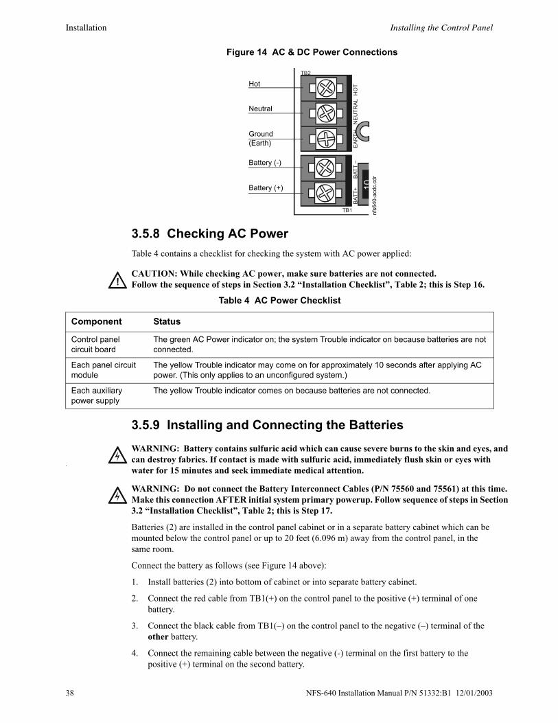
Installation Installing the Control Panel
d
. n
Figure 14 AC & DC Power Connections
3.5.8 Checking AC Power Table 4 contains a checklist for checking the system with AC power applied:
3.5.9 Installing and Connecting the Batteries
Batteries (2) are installed in the control panel cabinet or in a separate battery cabinet which can be mounted below the control panel or up to 20 feet (6.096 m) away from the control panel, in the same room.
Connect the battery as follows (see Figure 14 above):
1. Install batteries (2) into bottom of cabinet or into separate battery cabinet.
2. Connect the red cable from TB1(+) on the control panel to the positive (+) terminal of one battery.
3. Connect the black cable from TB1(–) on the control panel to the negative (–) terminal of the other battery.
4. Connect the remaining cable between the negative (-) terminal on the first battery to the positive (+) terminal on the second battery.
EAR
THH
OT
NEU
TRAL
BATT
–BA
TT+
TB1
TB2
nfs6
40-a
cdc.
cdr
Hot
Neutral
Ground (Earth)
Battery (-)
Battery (+)
!CAUTION: While checking AC power, make sure batteries are not connected. Follow the sequence of steps in Section 3.2 “Installation Checklist”, Table 2; this is Step 16.
Table 4 AC Power Checklist
Component Status
Control panel circuit board
The green AC Power indicator on; the system Trouble indicator on because batteries are not connected.
Each panel circuit module
The yellow Trouble indicator may come on for approximately 10 seconds after applying AC power. (This only applies to an unconfigured system.)
Each auxiliary power supply
The yellow Trouble indicator comes on because batteries are not connected.
!w
WARNING: Battery contains sulfuric acid which can cause severe burns to the skin and eyes, ancan destroy fabrics. If contact is made with sulfuric acid, immediately flush skin or eyes with water for 15 minutes and seek immediate medical attention.
!WARNING: Do not connect the Battery Interconnect Cables (P/N 75560 and 75561) at this timeMake this connection AFTER initial system primary powerup. Follow sequence of steps in Sectio3.2 “Installation Checklist”, Table 2; this is Step 17.
38 NFS-640 Installation Manual P/N 51332:B1 12/01/2003
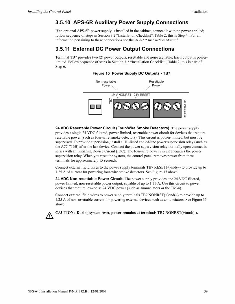
Installing the Control Panel Installation
3.5.10 APS-6R Auxiliary Power Supply ConnectionsIf an optional APS-6R power supply is installed in the cabinet, connect it with no power applied; follow sequence of steps in Section 3.2 “Installation Checklist”, Table 2; this is Step 4. For all information pertaining to these connections see the APS-6R Instruction Manual.
3.5.11 External DC Power Output ConnectionsTerminal TB7 provides two (2) power outputs, resettable and non-resettable. Each output is power-limited. Follow sequence of steps in Section 3.2 “Installation Checklist”, Table 2; this is part of Step 6.
Figure 15 Power Supply DC Outputs - TB7
24 VDC Resettable Power Circuit (Four-Wire Smoke Detectors). The power supply provides a single 24 VDC filtered, power-limited, resettable power circuit for devices that require resettable power (such as four-wire smoke detectors). This circuit is power-limited, but must be supervised. To provide supervision, install a UL-listed end-of-line power supervision relay (such as the A77-716B) after the last device. Connect the power supervision relay normally open contact in series with an Initiating Device Circuit (IDC). The four-wire power circuit energizes the power supervision relay. When you reset the system, the control panel removes power from these terminals for approximately 15 seconds.
Connect external field wires to the power supply terminals TB7 RESET(+)and(–) to provide up to 1.25 A of current for powering four-wire smoke detectors. See Figure 15 above.
24 VDC Non-resettable Power Circuit. The power supply provides one 24 VDC filtered, power-limited, non-resettable power output, capable of up to 1.25 A. Use this circuit to power devices that require low-noise 24 VDC power (such as annunciators or the TM-4).
Connect external field wires to power supply terminals TB7 NONRST(+)and(–) to provide up to 1.25 A of non-resettable current for powering external devices such as annunciators. See Figure 15 above.
+ – + –
TB7
Non-resettable Power
nfs6
40-d
cout
.cdr
Resettable Power
!CAUTION: During system reset, power remains at terminals TB7 NONRST(+)and(–).
NFS-640 Installation Manual P/N 51332:B1 12/01/2003 39
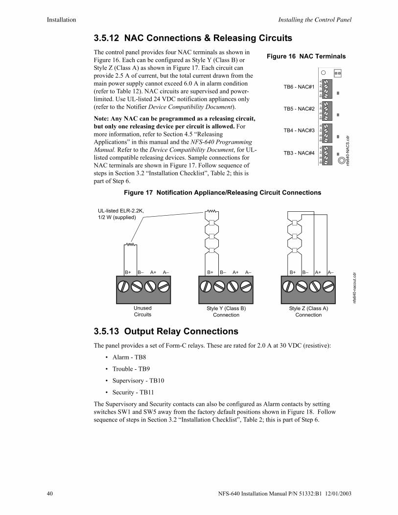
Installation Installing the Control Panel
3.5.12 NAC Connections & Releasing CircuitsThe control panel provides four NAC terminals as shown in Figure 16. Each can be configured as Style Y (Class B) or Style Z (Class A) as shown in Figure 17. Each circuit can provide 2.5 A of current, but the total current drawn from the main power supply cannot exceed 6.0 A in alarm condition (refer to Table 12). NAC circuits are supervised and power-limited. Use UL-listed 24 VDC notification appliances only (refer to the Notifier Device Compatibility Document).
Note: Any NAC can be programmed as a releasing circuit, but only one releasing device per circuit is allowed. For more information, refer to Section 4.5 “Releasing Applications” in this manual and the NFS-640 Programming Manual. Refer to the Device Compatibility Document, for UL-listed compatible releasing devices. Sample connections for NAC terminals are shown in Figure 17. Follow sequence of steps in Section 3.2 “Installation Checklist”, Table 2; this is part of Step 6.
Figure 17 Notification Appliance/Releasing Circuit Connections
3.5.13 Output Relay ConnectionsThe panel provides a set of Form-C relays. These are rated for 2.0 A at 30 VDC (resistive):
• Alarm - TB8
• Trouble - TB9
• Supervisory - TB10
• Security - TB11
The Supervisory and Security contacts can also be configured as Alarm contacts by setting switches SW1 and SW5 away from the factory default positions shown in Figure 18. Follow sequence of steps in Section 3.2 “Installation Checklist”, Table 2; this is part of Step 6.
B+B-
A+A-
B+B-
A+A-
B+B-
A+A-
B+B-
A+A-
Figure 16 NAC Terminals
TB6 - NAC#1
TB5 - NAC#2
TB4 - NAC#3
TB3 - NAC#4
nfs6
40-N
ACS.
cdr
B+ B– A+ A– B+ B– A+ A– B+ B– A+ A–
nfs6
40-n
acou
t.cdr
Style Y (Class B) Connection
Style Z (Class A) Connection
Unused Circuits
UL-listed ELR-2.2K, 1/2 W (supplied)
40 NFS-640 Installation Manual P/N 51332:B1 12/01/2003

Installing the Control Panel Installation
y
e .
e
Figure 18 Form-C Relay Connections
3.5.14 Backup-Alarm Switches
Backup alarm switches are provided that enable NACs and the alarm relay to activate during a backup alarm condition. If the main board’s microcontroller fails and an alarm is reported by any detector or a monitor module that has backup reporting enabled, the NAC will turn on if the corresponding switch was enabled. The alarm will activate during microcontroller failure regardless of the settings of Switch 6-9.
• Switch 6 - NAC#1
• Switch 7 - NAC#2
• Switch 8 - NAC#3
• Switch 9 - NAC#4
So, for example, if Switch 6 and Switch 8 were enabled at the time of an alarm during microcontroller failure, NAC#1 and NAC#3 would activate. Follow sequence of steps in Section 3.2 “Installation Checklist”, Table 2; this is Step 7.
3.5.15 Installing a Transmitter Module TM-4 TM-4 is power-limited. Connections are on TB7 nonresettable output and TB13 EIA-485 ACS Mode. Refer to the Transmitter Module TM-4 installation document for installation details.
ALARM RELAYNO NC C
TROUBLE RELAYNO NC C
SUPERVISORY RELAYNO NC C
SECURITY RELAYNO NC C
TB8 TB9 TB10
TB11
SW1 SW5
SUPV ALARM SECUR ALARM
SW1 set to SupervisorSW5 set to SecurityMove switch to oppositposition to set to Alarm
nfs6
40-re
lay.
cdr
!WARNING: Do not enable the BACKUP option switch for any of the four Notification AppliancCircuits (NACs) if they are used for releasing functions!
Figure 19 Backup Alarm Switches
SW6
NAC
SW7
ENAB
D
ISAB
SW8
SW9
1 3
2 4
nfs6
40-s
w6-
9.cd
r
NFS-640 Installation Manual P/N 51332:B1 12/01/2003 41
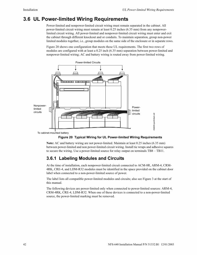
Installation UL Power-limited Wiring Requirements
3.6 UL Power-limited Wiring RequirementsPower-limited and nonpower-limited circuit wiring must remain separated in the cabinet. All power-limited circuit wiring must remain at least 0.25 inches (6.35 mm) from any nonpower-limited circuit wiring. All power-limited and nonpower-limited circuit wiring must enter and exit the cabinet through different knockout and or conduits. To maintain separation, group non-power limited modules together, i.e., group modules on the same side of the enclosure or in separate rows.
Figure 20 shows one configuration that meets these UL requirements. The first two rows of modules are configured with at least a 0.25 inch (6.35 mm) separation between power-limited and nonpower-limited wiring; AC and battery wiring is routed away from power-limited wiring.
Figure 20 Typical Wiring for UL Power-limited Wiring Requirements
Note: AC and battery wiring are not power-limited. Maintain at least 0.25 inches (6.35 mm) between power-limited and non power-limited circuit wiring. Install tie wraps and adhesive squares to secure the wiring. Use a power-limited source for relay output on terminals TB8 – TB11.
3.6.1 Labeling Modules and CircuitsAt the time of installation, each nonpower-limited circuit connected to ACM-8R, ARM-4, CRM-4RK, CRE-4, and LDM-R32 modules must be identified in the space provided on the cabinet door label when connected to a non-power-limited source of power.
The label lists all compatible power-limited modules and circuits; also see Figure 3 at the start of this manual.
The following devices are power-limited only when connected to power-limited sources: ARM-4, CRM-4RK, CRE-4, LDM-R32. When one of these devices is connected to a non-power-limited source, the power-limited marking must be removed.
Power-limited Circuits
Power-limitedcircuits
Nonpower-limitedcircuits
nfs6
40-p
wrlm
twir.
cdr
To cabinet-mounted battery
42 NFS-640 Installation Manual P/N 51332:B1 12/01/2003

Installing Panel Circuit Modules Installation
3.7 Installing Panel Circuit Modules3.7.1 OverviewInstallation of a panel circuit module is divided into five (5) operations:
• Mounting an optional expander board to the module (e.g. mounting ICE-4 onto an ICM-4RK).
• Connecting communication ribbon cables from Control Panel to the module.
• Installing the module onto a chassis.
• Connecting modules to the power supply.
• Field wiring the module.
Refer to Section 2.10 “Panel Circuit Modules” for a complete list of modules and their expanders.
3.7.2 Mounting Expander BoardsExpander Board Modules, such as ICE-4 or CRE-4, need to be mounted onto their respective modules (ICM-4RK, CRM-4RK) prior to installation onto a chassis. To mount an Expander Module:
1. Remove one module support screw and set it aside for later use.
2. Replace the module support screw with one module stand-off.
3. Repeat Steps 1 and 2 for the three remaining module support screws.
4. Insert pins on the front of the expander board into connector on the back of the module. Make sure the pins are in line; then, press the two units together until they snap into place.
5. Install the four module support screws (removed earlier) through the back of the expander board and into the stand-offs. Tighten securely.
Figure 21 illustrates the steps.
Figure 21 Expander Module Installation
Install module stand-off
Remove existing module support screw
Plug in the expander board
Secure with module support screws
nfs6
40-p
cmod
s.cd
r
Steps 1 & 2
Steps 4 & 5
NFS-640 Installation Manual P/N 51332:B1 12/01/2003 43
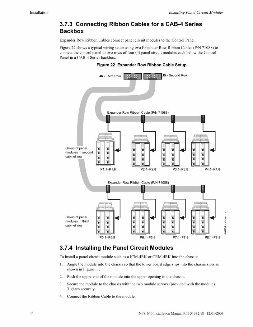
Installation Installing Panel Circuit Modules
3.7.3 Connecting Ribbon Cables for a CAB-4 Series BackboxExpander Row Ribbon Cables connect panel circuit modules to the Control Panel.
Figure 22 shows a typical wiring setup using two Expander Row Ribbon Cables (P/N 71088) to connect the control panel to two rows of four (4) panel circuit modules each below the Control Panel in a CAB-4 Series backbox.
Figure 22 Expander Row Ribbon Cable Setup
3.7.4 Installing the Panel Circuit ModulesTo install a panel circuit module such as a ICM-4RK or CRM-4RK into the chassis:
1. Angle the module into the chassis so that the lower board edge slips into the chassis slots as shown in Figure 11.
2. Push the upper end of the module into the upper opening in the chassis.
3. Secure the module to the chassis with the two module screws (provided with the module). Tighten securely.
4. Connect the Ribbon Cable to the module.
MODULETYPE
LAMPS
SWITCH
MODULETYPE
LAMPS
SWITCH
MODULETYPE
LAMPS
SWITCH
MODULETYPE
LAMPS
SWITCH
MODULETYPE
LAMPS
SWITCH
MODULETYPE
LAMPS
SWITCH
MODULETYPE
LAMPS
SWITCH
MODULETYPE
LAMPS
SWITCH
MODULETYPE
LAMPS
SWITCH
MODULETYPE
LAMPS
SWITCH
MODULETYPELAMPS
SWITCH
MODULETYPELAMPS
SWITCH
MODULETYPELAMPS
SWITCH
MODULETYPELAMPS
SWITCH
MODULETYPELAMPS
SWITCH
MODULETYPELAMPS
SWITCH
P1.1–P1.8 P2.1–P2.8 P3.1–P3.8 P4.1–P4.8
nfs6
40-ic
mrib
bon.
cdr
Expander Row Ribbon Cable (P/N 71088)
Expander Row Ribbon Cable (P/N 71088)
Group of panel modules in third cabinet row
J5 - Second Row
P5.1–P5.8 P6.1–P6.8 P7.1–P7.8 P8.1–P8.8
J6 - Third Row
Group of panel modules in second cabinet row
44 NFS-640 Installation Manual P/N 51332:B1 12/01/2003

Installing Panel Circuit Modules Installation
3.7.5 Connecting ICM-4RK and ICE-4 ModulesThe total current available for any group of Notification Appliance Circuits (NACs), other than the four NACs on the control panel, cannot exceed the following:
• 6.0 A when powered from the APS-6R
• 1.25 A when powered from a NFS-640 DC power output terminal
Shown below are the wire connectors on the bottom of the ICM-4RK and the ICE-4 modules.
Figure 23 ICM-4RK/ICE-4 Connectors
Power Supply ConnectionsThe figure below illustrates typical connections from main power supply.
Figure 24 Main Power Supply Connection
Multiple Power SuppliesCut JP1 and JP2 on ICM-4RK when supplying 24V power from two separate sources to the ICM-4RK. ICM-4RK circuits 1-2 will receive their power from J5; ICM-4RK circuits 3-4 will receive their power from J6.
Cut JP1 and JP2 on ICE-4 when supplying power from separate sources to expander circuits 5-8. ICM-4RK circuits 5-6 will receive power from J5 on the ICE-4 and ICM-4RK circuits 7-8 will receive power from J6 on the ICE-4.
See Figure 25 for jumper locations.
nfs6
40-ic
mco
nn.c
dr
ICM-4RK
ICE-4
J5
J6
J5
J6
J5ICM-4J6
ICE-4J5
TB7
24V 24V RESETNONRST
+ – + –
Power Cable P/N 71091
nfs6
40-ic
mna
c.cd
r
Eight NACs that share 1.25 A
TB7 on Control Panel
Bell power cable (P/N 75400) or alternate Power Harness (P/N 71093, with lugs removed and wires stripped)
Black wire (–), Blue wire (+)
NFS-640 Installation Manual P/N 51332:B1 12/01/2003 45
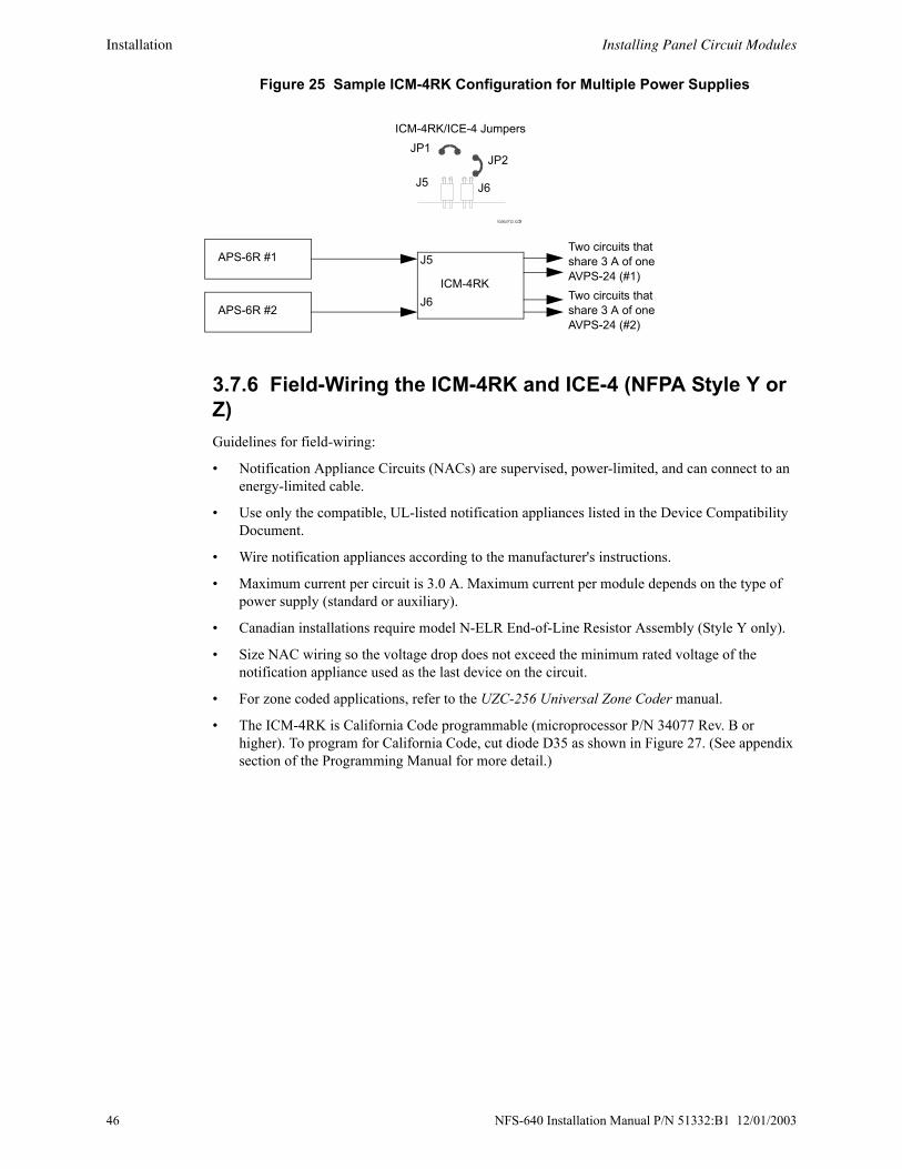
Installation Installing Panel Circuit Modules
Figure 25 Sample ICM-4RK Configuration for Multiple Power Supplies
3.7.6 Field-Wiring the ICM-4RK and ICE-4 (NFPA Style Y or Z) Guidelines for field-wiring:
• Notification Appliance Circuits (NACs) are supervised, power-limited, and can connect to an energy-limited cable.
• Use only the compatible, UL-listed notification appliances listed in the Device Compatibility Document.
• Wire notification appliances according to the manufacturer's instructions.
• Maximum current per circuit is 3.0 A. Maximum current per module depends on the type of power supply (standard or auxiliary).
• Canadian installations require model N-ELR End-of-Line Resistor Assembly (Style Y only).
• Size NAC wiring so the voltage drop does not exceed the minimum rated voltage of the notification appliance used as the last device on the circuit.
• For zone coded applications, refer to the UZC-256 Universal Zone Coder manual.
• The ICM-4RK is California Code programmable (microprocessor P/N 34077 Rev. B or higher). To program for California Code, cut diode D35 as shown in Figure 27. (See appendix section of the Programming Manual for more detail.)
ICM-4RK/ICE-4 Jumpers
APS-6R #1
APS-6R #2
J6J5
JP1JP2
ICM-4RKJ6
J5Two circuits that share 3 A of one AVPS-24 (#1)Two circuits that share 3 A of one AVPS-24 (#2)
46 NFS-640 Installation Manual P/N 51332:B1 12/01/2003

Installing Panel Circuit Modules Installation
Figure 26 Field-Wiring an ICM-4RK/ICE-4
Figure 27 Location of D35 on ICM-4RK Circuit Board
3.7.7 Connecting CRM-4RK/CRE-4 ModulesGuidelines for field-wiring the CRM-4RK and the CRE-4:
• Provide Form-C relay contacts (silver alloy) used for medium duty switching or pilot duty.
• Terminals will accept wire sizes from 12 AWG to 18 AWG (3.1 to 0.78 mm2).
• Activation of a module or expander relay occurs automatically when an alarm is detected on a programmed IDC.
• UL contact ratings are 5 A at 125 VAC (resistive) or 30 VDC (resistive) and 2 A at 125 VAC (inductive).
• For more information, refer to Section 3.6 “UL Power-limited Wiring Requirements”.
• For typical field-wiring connections, refer to Figure 28.
B+ A+ A– B– B+ A+ A– B– B+ A+ A– B– B+ A+ A– B–
Jumpers for unused circuits
4.7K, 1/2 watt ELR P/N 71252
UL-listed 24 VDC Polarized Devices
ICM
4wire
-YB.
cdr
Typical NFPAStyle Z (Class A) NAC
Typical NFPAStyle Y (Class B) NAC
Jumpers for unused circuits
Cut D35 on the circuit board to produce California code.
icm
-4rk
-d35
.cdr
NFS-640 Installation Manual P/N 51332:B1 12/01/2003 47

Installation Auxiliary Relay Module (ARM-4): Product-Specific Details
Figure 28 Field-Wiring a CRM-4RK or CRE-4 Module
3.8 Auxiliary Relay Module (ARM-4): Product-Specific Details3.8.1 OverviewIf a CRM-4RK/CRE-4 is to be incorporated into the control panel and an ARM-4 is being driven by it, note the following:
• Each ARM-4 must be supported by one CRM-4RK or one CRE-4.
• If using ARM-4’s for both modules, mount two ARM-4’s in separate positions.
• If mounted in FACP enclosure keep all non-power limited wiring separate from power limited wiring.
For ease of installation, service, and wiring mount the ARM-4 module in a position on the chassis that will not have any other module or expander board in front of it. However, you can install the ARM-4 directly behind the CRM-4RK or CRE-4.
ARM-4 mounts in the second, third or fourth row of a CAB-4 series backbox, against the back of a chassis CHS-4 or CHS-4L. The ARM-4 may be mounted in any of the 8 adjacent backbox positions the cable can reach.
3.8.2 InstallationTo install the Auxiliary Relay Module in the chassis:
1. Select a mounting position for the module on the chassis.
2. Install two (2) mounting stand-offs onto the studs of the chassis, at the selected location, as shown in Figure 12. Tighten securely.
3. Install three (3) support stand-offs, with screws, onto the PC board in the locations shown in Figure 12 or in the two right-hand positions on the first row. Tighten securely.
4. Position module over the stand-offs on the chassis; fasten the module to the chassis with the two (2) retaining screws. Tighten securely.
5. Connect one end of the Cable (P/N 71092) to plug P1 on the ARM-4.Note: The other end of the cable is connected to jumper JP5 on the CRM-4RK or CRE-4.
6. Connect all available external wiring at this time. Refer to Section 3.8.3 “Field Wiring an Auxiliary Relay Module”.
CONTROLRELAY
CONTROLRELAY
Optional CRE-4 Control Relay Expander
CR
EEXP
CO
-RK.
cdr
CRM-4RK
Typical connections for a Form-C control relay in normal position.
48 NFS-640 Installation Manual P/N 51332:B1 12/01/2003

Auxiliary Relay Module (ARM-4): Product-Specific Details Installation
Figure 29 ARM-4 Stand-off & Terminal Locations
3.8.3 Field Wiring an Auxiliary Relay ModuleThe figure above shows terminal assignments for ARM-4 module control relays K1-K4, which control nonpower-limited circuits. Power-limited and nonpower-limited circuit wiring must remain separated by at least 0.25 inch (6.35 mm) within the cabinet and exit the cabinet though different knockouts, conduits, or both.
Note: For more information, refer to Section 3.6 “UL Power-limited Wiring Requirements”.
The table contains contact ratings for relays K1-K4 on the ARM-4 module:
P2
P1
NC NO C
NC NO C NC NO C
NC NO CCom K1 K2 K3 K4 – + + + +
ARM
-4.c
dr
P-1Connection for Cable P/N 71092
These 3 holes for support stand-offs.
These 2 holes for mounting stand-offs.
Terminal Assignments(typ. 4 places)
Table 5 Contact Ratings for K1-K4 on the ARM-4 Module
Resistive Load Contacts
Normally Open (N.O.) Normally Closed (N.C.)
125 VAC 20 A 10 A
30 VDC 20 A 10 A
NFS-640 Installation Manual P/N 51332:B1 12/01/2003 49

Installation Installing Remote Printers and/or CRT
3.9 Installing Remote Printers and/or CRT3.9.1 Custom Cable FabricationA custom cable needs to be fabricated to connect the PRN-5 Printer, Keltron Printer or the CRT-2 Monitor to the system. Length of the cable will vary with each installation, but should not exceed a maximum length of 50 feet (15.24 meters). Printer must be installed in the same room as panel. Construct cable as follows:
1. Using overall foil/braided-shield twisted-pair cable, properly connect one end to the DB-25 Connector using the wiring specifications shown in the table below. (Custom cable kit P/N 90106 is provided.)
2. Tighten clamp on connector to secure cable.
3.9.2 Installing and Configuring the PRN-5 PrinterWhen connected to the Control Panel via an EIA-232 interface, the PRN-5 prints a copy of all status changes within the control panel and time-stamps the printout with the time of day and date the event occurred. It provides 80 columns of data on standard 9" by 11" tractor-feed paper.
Note: You can also use the EIA-232 printer interface with UL-listed I.T.E. equipment, such as personal computers, to monitor the control panel for supplementary purposes.
This section contains information on connecting a printer to the control panel and for setting the printer options.
Connecting a Remote PRN PrinterRemote printers require a 120 VAC, 50/60 Hz primary power source. If required for the fire alarm system configuration (for example, a Proprietary Fire Alarm System), a remote printer requires a secondary power source (battery backup). Because a secondary power source is not provided, use a separate Uninterruptable Power Supply (UPS) that is UL-listed for Fire Protective Signaling. You may use your building emergency power supply, so long as it meets the power continuity requirements of NFPA 72. Refer to NFPA 72 for further details.
Connect the remote printer to the Control Panel as follows:
1. Connect the three (3) open leads of the custom cable to the TB14 terminal block on the control panel as shown in Figure 30.
2. Plug the DB-25 connector end of the custom cable into the EIA-232 port of the remote printer. Tighten securely.
DB-25 Connector (Custom cable kit 90106) TB14 on Control Panel
Pin 3 TX
Pin 2 RX
Pin 7 REF
50 NFS-640 Installation Manual P/N 51332:B1 12/01/2003

Installing Remote Printers and/or CRT Installation
Figure 30 Remote Printer Connections
Setting Printer OptionsRefer to the documentation supplied with the PRN-5 for instructions on using the printer menu controls. Set the printer options (under the menu area) according to the settings listed in Table 6.
3.9.3 Installing and Configuring a Keltron PrinterConnect the remote printer to the Control Panel as follows:
1. Connect the three (3) open leads of the custom cable to the TB14 terminal block on the control panel as shown in the figure below.
2. Connect DC power from TB7 terminal block on the control panel as shown in the figure below.
3. Plug the DB-25 connector end of the custom cable into the EIA-232 port of the Keltron printer. Tighten securely.
TB14 TB15
PRINTERTX RX REF
PC/CRTTX RX REF
Note: Outputs are power-limited but are not supervised.
nfs6
40-p
rn5c
onn.
cdr
DB-25 connector on PRN-5 (female socket shown)
Control Panel
Terminate one end of shield at backbox
Table 6 PRN-5 Setup Options
Option Setting Option Setting
L/R AdjustFontLPIESC CharacterBidirectional Copy
0HS Draft6 CPIESCON
CPISkipEmulateI/O BufferSerial Baud
Format ProtocolCharacter SetS1. ZeroAuto LFMENULOCKPAPERBIN 1BIN 2SINGLEPUSH TRAPULL TRAPAP ROLLPAPOPT
10 CPI0.5Epson
36K
960024007 Bit, Even, 1 StopXON/XOFFStandardOnOff
12/72"12/72"12/72"12/72"12/72"12/72"No
CG-TABCountryAuto CR
GraphicE-USE ASCII1S
Color OptionFormlen Lines Standard
Not Installed
6 LPI-60Executive 10.5"
NFS-640 Installation Manual P/N 51332:B1 12/01/2003 51
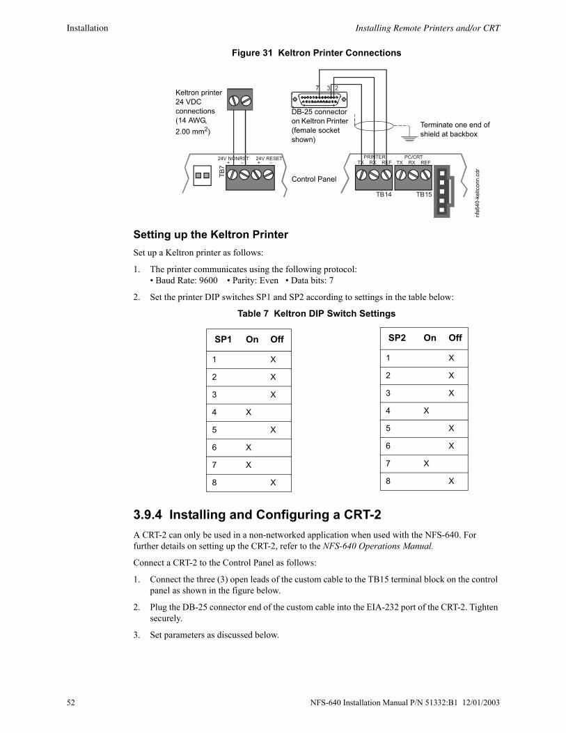
Installation Installing Remote Printers and/or CRT
Figure 31 Keltron Printer Connections
Setting up the Keltron PrinterSet up a Keltron printer as follows:
1. The printer communicates using the following protocol:• Baud Rate: 9600 • Parity: Even • Data bits: 7
2. Set the printer DIP switches SP1 and SP2 according to settings in the table below:
Table 7 Keltron DIP Switch Settings
3.9.4 Installing and Configuring a CRT-2 A CRT-2 can only be used in a non-networked application when used with the NFS-640. For further details on setting up the CRT-2, refer to the NFS-640 Operations Manual.
Connect a CRT-2 to the Control Panel as follows:
1. Connect the three (3) open leads of the custom cable to the TB15 terminal block on the control panel as shown in the figure below.
2. Plug the DB-25 connector end of the custom cable into the EIA-232 port of the CRT-2. Tighten securely.
3. Set parameters as discussed below.
TB14 TB15
PRINTERTX RX REF
PC/CRTTX RX REF
24V 24V NONRST RESET+ – + –
TB7
nfs6
40-k
eltc
onn.
cdr
DB-25 connector on Keltron Printer (female socket shown)
Keltron printer 24 VDC connections (14 AWG, 2.00 mm2)
Control Panel
Terminate one end of shield at backbox
SP1 On Off
1 X
2 X
3 X
4 X
5 X
6 X
7 X
8 X
SP2 On Off
1 X
2 X
3 X
4 X
5 X
6 X
7 X
8 X
52 NFS-640 Installation Manual P/N 51332:B1 12/01/2003

Installing Remote Printers and/or CRT Installation
Figure 32 Connecting a CRT-2
Setting CRT-2 ParametersThe CRT-2 communicates with the control panel through a protocol defined by thirteen groups of parameters. To access a parameter group, press the corresponding function key (F1-F12) as shown in Table 8 below. You can then program parameters in each group.
Enter the CRT-2 setup menu by pressing and holding the <Ctrl> key while pressing the <Scroll Lock> key. Use arrow keys to move through the selections in each setup group; press the space bar to view the options for each parameter. When finished programming all setup groups, press the <Pause> key. To save all changes, press <Y>.
Table 8 shows the standard settings for using the CRT-2 with the NFS-640; for one instance where these settings may change slightly see Section 3.9.6 “Connecting Multiple Printers, CRTs, or CRT/PRN Combination”. The basic settings for using the CRT-2 with NFS-640 are:• Baud Rate 9600 • Data format 8 1 N • Protocol xon/off.
Note: This section covers installation only; for information on how the CRT-2 functions as part of the fire alarm system, see the NFS-640 Operations Manual.
TB14 TB15
PRINTERTX RX REF
PC/CRTTX RX REF
DB-25 connector on CRT-2 (female socket shown)
Control Panel
nfs6
40-c
rt2co
nn.c
dr
Terminate one end of shield at backbox
NFS-640 Installation Manual P/N 51332:B1 12/01/2003 53

Installation Installing Remote Printers and/or CRT
3.9.5 Connecting a PCA PC can be hooked up to the Control Panel EIA-232 port to allow the VeriFire Tools programming utility to upload and download the operating program of the control panel. Refer to the insert in the VeriFire Tools CD and to the program’s on-line help function for instructions.
Note: Download operations that change the basic program of the control panel must be performed by responsible service personnel in attendance at the control panel. After downloading a program, test the control panel in accordance with NFPA 72-1999.
Table 8 Standard CRT-2 Settings for Use with NFS-640
Function Key CRT-2 Parameters
F1: Quick (“Read Status” key)
Emulation=CRT-2Comm Mode=Full DuplexEnhanced=On
EIA Baud Rate=9600Aux Baud Rate=9600Language=U.S.
EIA Data Format=8/1/NAux Data Format=8/1/NHost/Printer=EIA/Aux
F2:Genrl(“Alter Status” key)
Emulation=CRT-2Auto Font Load=OnMonitor Mode=OffHost/Printer=EIA/Aux
Enhanced=OnAuto Page=OffBell Volume=09
Auto Wrap=OffAuto Scroll=OnWarning Bell=On
F3: Displ(“Prog” key)
Page Length=24Display Cursor=OnColumns=80Scroll=Jump
Screen Length=26 LinesCursor=Blink LineWidth Change Clear=OffRefresh Rate=60 Hz
Screen Video=NormalAuto Adjust Cursor=OnSpeed=NormalOverscan Borders=Off
F4: Kybd(“Spl Funct” key)
Language=U.S.Keyclick=OffKey Lock=Caps
Char Set Mode=ASCIIKey Repeat=OffKeyboard Present=Yes
Key Mode=ASCIIMargin Bell=Off
F5: Keys (“Prior” key)
Enter Key=<CR>Alt Key=MetaPound Key=U.S.
Return Key=<CR>Disconnect=Pause
Backspace=<BS>/<DEL>Desk Acc=Disabled
F6: Ports(“Next” key)
EIA Baud Rate=9600Aux Baud Rate=9600EIA Xmt=Xon-XoffAux Xmt=Xon-XoffEIA Break=OffAux Break=Off
EIA Data Format=8/1/NAux Data Format=8/1/NEIA Recv=Xon-Xoff(XPC)Aux Recv=Xon-Xoff(XPC)EIA Modem Control=OffAux Modem Control=Off
EIA Parity Check=OnAux Parity Check=OnEIA Xmt Pace=BaudAux Xmt Pace=BaudEIA Disconnect=2 secAux Disconnect=2 sec
F7: Host(“Auto Step” key)
Comm Mode=Full DuplexRecv <DEL>=IgnoreSend Block Term=<CR>
Local=OffSend ACK=OnNull Suppress=On
Recv <CR>=<CR>Send Line Term=<CR><LF>
F8: Print (“Activ Signal” key)
Prnt Line Term=<CR><LF> Prnt Block Term=<CR> Secondary Recv=Off
F9: Emul Attribute=PageWPRT Intensity=DimWPRT Blink=OffStatus Line=Off
Bright Video=OffWPRT Reverse=OffDisplay NV Labels=OffFkey Speed=Normal
Page Edit=OffWPRT Underline=OffSave Labels=On
F10 Setup Group F10 does not affect communications with the control panel.
F11 Setup Group F11 does not affect communications with the control panel.
F12: Prog(“Ack Step” key)
Program the function keys as follows: F1 ~A F2 ~B F3 ~C F4 ~D F5 ~E F6 ~F F7 ~G F8 ~H F9 ~I F10 ~J F11 ~K F12 ~L F13 ~M F14 ~N F15 ~O F16 ~P Shift F13 ~Q
54 NFS-640 Installation Manual P/N 51332:B1 12/01/2003

Installing Remote Printers and/or CRT Installation
3.9.6 Connecting Multiple Printers, CRTs, or CRT/PRN CombinationConnecting multiple devices requires changing the CRT-2 setup using the F1(Quick) menu:
• Set Host/Printer=EIA/AUX.
• Set EIA Data Format=8/1/N.
• If the AUX device is a printer, set the Printer and AUX Data Format=7/1/E.
• If the AUX device is a second CRT-2, set the AUX Data Format=8/1/N.
Connect multiple devices as shown below:
Figure 33 Connecting Multiple Devices on the EIA-232 Circuit
7 3 2
7 3 2
7 3 2
To Control PanelTB15-REFTB15-TXTB15-RX
To EIA-232 port of CRT-2 (female socket shown)
To AUX Port of CRT-2 (female socket shown)
To EIA-232 port of next CRT-2 or PRN (female socket shown)
prnc
rt-co
nn.c
dr
Note: For wire requirements, see Table 16 in Appendix B “Electrical Specifications”.
NFS-640 Installation Manual P/N 51332:B1 12/01/2003 55

Installation Wiring a Signaling Line Circuit (SLC)
3.10 Wiring a Signaling Line Circuit (SLC)OverviewCommunication between the control panel and intelligent and addressable initiating, monitor, and control devices takes place through a Signaling Line Circuit (SLC). You can wire an SLC to meet the requirements of NFPA Style 4, Style 6, or Style 7 circuits. This manual provides requirements and performance details specific to this control panel; for installation information and general information, refer to the SLC Wiring Manual.
WiringMaximum wiring distance of an SLC using 12 AWG (3.1 mm2) wire:
• Style 4 -12,500 feet (3810 meters) total twisted-pair.
• Style 6 & 7 -10,000 feet (3048 meters) total twisted-pair.
CapacityThe NFS-640 provides one (1) SLC, with a total capacity of 318 intelligent/addressable devices:
• 01-159 intelligent detectors
• 01-159 monitor and control modules
An optional expander board provides one (1) additional SLC, with the same capacity.
InstallationThis control panel supports one or two SLC loops; a second SLC loop is obtained by installing an LEM-320 module. SLC loop #1 connects to TB16 on the control panel; SLC loop #2 connects to TB1 on the LEM-320. For details on designing, installing and configuring SLC loops, see the SLC Wiring Manual.
Figure 34 SLC Loop Connections and Wiring
B+ A+ B- A- B+ A+ B- A-
T-Tapping is not allowed on a four-wire SLC.
SLC B (output loop)
SLC A (loop return)
SLC B SLC A
Style 4 SLC Loops Style 6 SLC Loops
TB1B+ A+ B- A-
SLC1 B+ A+ B- A-
TB16SLC Loop #2 Connectionson Loop Expander Module
SLC Loop #1 Connections on FACP’s main circuit board
Use either SLC Loop #1
or SLC Loop #2 nfs6
40-s
lclo
ops.
cdr,
nfs6
40-s
lc-tb
.cdr
, LEM
320-
slc-
tb.c
dr
56 NFS-640 Installation Manual P/N 51332:B1 12/01/2003

Section 4 Applications
4.1 Overview
Municipal Box (Auxiliary)Municipal Box applications require a TM-4 Transmitter module. Refer to the Transmitter Module TM-4 installation document for installation details.
Chapter Covers the following topics
Section 4.2 “NFPA 72-1999 Central or Remote Station Fire Alarm System (Protected Premises Unit)”
How to install UDACT with the control panel for use as a NFPA Central or Remote Station Fire Alarm System (Protected Premises Unit)
Section 4.3 “NFPA 72-1999 Proprietary Fire Alarm Systems”
How to set up a Protected Premises Unit to communicate with a listed compatible Protected Premises Receiving Unit.
Section 4.4 “Fire/Security Applications”
How to use the control panel as a combination Fire/Security system, including the following:• Installing a Security Tamper Switch into the cabinet• Circuit Wiring
Section 4.5 “Releasing Applications”
How to install the following releasing applications:• a Releasing Device to the Control Panel (NAC integral circuits)• a Releasing Device to the FCM-1 Module• an NBG-12LRA Agent Release-Abort Station
NFS-640 Installation Manual P/N 51332:B1 12/01/2003 57

Applications NFPA 72-1999 Central or Remote Station Fire Alarm System (Protected Premises Unit)
h
4.2 NFPA 72-1999 Central or Remote Station Fire Alarm System (Protected Premises Unit)
Figure 35 shows typical wiring diagram for a NFPA 72-1999 Central Station Fire Alarm System (Protected Premises Unit) or a Remote Station Fire Alarm System (Protected Premises Unit) using the Universal Digital Alarm Communicator/Transmitter (UDACT) and control panel. This provides typical wiring only; connect and program the UDACT according to the directions given in the UDACT Instruction Manual.
Note: An NFPA 72-1999 Central Station requires 24 hours of standby power; an NFPA 72-1999 Remote Station requires 60 hours of standby power.
Figure 35 Typical Wiring Diagram for a Central Station Fire Alarm System
Note: Install a UL-listed 120 ohm End-of-Line resistor (P/N 71244) UDACT TB1 terminals 3 and 4 if this is the last or only device on EIA-485 line.
Note: This application can also be done with the TM-4 Transmitter; refer to the Transmitter Module TM-4 document for more details.
TB13
EIA-485+ ACS –
24V NONRST 24V RESET+ – + –
TB7
UDACT in ABS-8R(shown with cover removed)
Solid eartground
To supervised phone lines
Ferrite coresP/N 29090FACP Cabinet
EIA-485(ACS Mode)
24 VDC Nonresettable power
Supervised and power-limited EIA-485 and power wiring
nfs6
40-u
dact
.cdr
58 NFS-640 Installation Manual P/N 51332:B1 12/01/2003

NFPA 72-1999 Proprietary Fire Alarm Systems Applications
4.3 NFPA 72-1999 Proprietary Fire Alarm SystemsWhen connected and configured as a protected premises unit with UDACT, the NFS-640 will automatically transmit General Alarm, General Trouble, and General Supervisory signals to a listed compatible Protected Premises Receiving Unit. See the UDACT Manual for compatible receiving units. A simplified drawing of connections between a receiving unit and an NFS-640 protected premises unit is shown in Figure 36.
Connect the receiving unit to the protected premises unit as shown in Section 4.2 “NFPA 72-1999 Central or Remote Station Fire Alarm System (Protected Premises Unit)”.
For information on installing and programming the Receiving unit, refer to the documentation for that control panel.
Figure 36 Typical Proprietary Fire Alarm Systems Wiring Connections
4.4 Fire/Security Applications Note: NFS-640 is not approved for use in security applications in Canada.
4.4.1 General OperationThe control panel can be used as a combination Fire/Security system when installed and operated according to the instructions in this section.
For security applications, program one or more monitor module (listed for security applications) with the SECURITY Type Code, and wire as shown in Figure 38. Activating this type of module lights the SECURITY LED, and displays a security alarm condition on the control panel LCD display. The panel sounder will sound until the Security alarm is acknowledged. You can also program additional sounders or output devices to activate with the security alarm initiating device. The SECURITY Type Code is designed to indicate an alarm as follows: (a) on an open or short circuit; or (b) on a ±50% change in resistance value from the End-of-Line resistor value.
A tamper switch installed in the cabinet door will indicate a door tamper condition whenever the door is open. If the control panel indicates a Security alarm, you can acknowledge, silence, and reset the condition from the control panel.
When the system resets, a 30-second exit timer starts. During this time the tamper switch and all Security alarms are ignored. There is no entrance delay timer.
NFS-640 Protected Premises Unit
Compatible Receiving Unit (see UDACT Manual)
Telephone line & backup
UDACT
NFS-640
NFS-640 Installation Manual P/N 51332:B1 12/01/2003 59

Applications Fire/Security Applications
For bypass of security zones, use the DISABLE routine (covered in the Status Change section of the NFS-640 Operations Manual) for Security type devices.
4.4.2 Installing a Security Tamper SwitchFollow the instructions below to wire the cabinet with a Security Tamper Switch kit model STS-1.
Figure 37 Installing the STS-1 Security Tamper Switch
4.4.3 Receiving Unit For applications requiring transmission of security alarm information to a central receiving unit, the control panel may be connected via a UDACT to a compatible receiving unit (see the UDACT Manual). For information on configuring the Receiving unit for Combination Fire/Security applications, refer to the documentation for that control panel.
!WARNING: Damage can result from incorrect wiring connections.
nfs6
40-s
ts1.
cdr
STS-1 mounting location(side opposite of door hinges)
Connect to J10 “Tamper”
Step Action
1 Install the STS-1 Tamper Switch onto the side of the backbox opposite the door hinge, pushing the switch through the opening until it snaps into place.
2 Install the magnet on the same side of the cabinet door as the lock. Push the magnet through the opening in the door until it snaps into place.
3 Connect the STS-1 connector to J10 (Tamper) on the Control Panel.
60 NFS-640 Installation Manual P/N 51332:B1 12/01/2003

Fire/Security Applications Applications
4.4.4 ProgrammingThe control panel can communicate with any number of security devices. To do so, program the points as follows:
1. Select the address of the module(s) to be used for security.
2. Select the Type Code SECURITY.
Note: For detailed instruction on programming Type Codes, refer to the NFS-640 Programming Manual.
NFS-640 Installation Manual P/N 51332:B1 12/01/2003 61

Applications Fire/Security Applications
4.4.5 Wiring for Proprietary Security Alarm ApplicationsTypical wiring for proprietary security alarm applications with FCM-1 modules or XP5-M modules. Note the following:
• The module is programmed with software SECURITY Type Code.
• Supplementary use only applies to UL-listed systems.
• NAC devices used for security cannot be shared with fire NAC devices.
• Refer to the Device Compatibility Document for compatible NAC devices.
• All monitor modules used for security application must be installed in the NFS-640 cabinet with STS-1 Security Tamper Switch.
Figure 38 Wiring Diagram for Proprietary Security Alarm Applications
8
9 8
8
9
9
10111213
14150
0
1
1
2
2
3
3
4
4
5
5
6
6
7
7
0
12
34
76
5
TENS
ONESADDRESSLOOP
–
+
FCM-1
UL-listed, normally-closed security switch
UL-listed, normally-open security switch
SW101
ON
ON
ON
ON
SW 201 SW 301 SW 401
ON
SW 501
Enable
Enable
Enable
Enable
SW102
SW1
SW 2
Base Address
SW202 SW302 SW402 Enable
SW 502
1
0 57
8
62
34915
131214
10
TB4
TB1
TB5
TB2
TB6
TB3
SLC B- B+ A- A+ B+B-B+B-B+B-B+B-B+B-
0 5
(+)(-)
UL-listed, normally-closed security switch
UL-listed, normally-open security switch
UL-listed, normally-open security switch
UL-listed, normally-closed security switch
XP5-M
SLC Channel A or B
UL-listed 47K End-of-Line Resistor (provided with module)
SLC Channel A or B
NFS-640 Protected Premises Unit
NFS-640 Protected Premises Unit
nfs6
40-b
urgl
arxp
5m.c
dr
nfs6
40-b
urg.
cdr
UL-listed 47K End-of-Line Resistor (provided with module)
62 NFS-640 Installation Manual P/N 51332:B1 12/01/2003

Releasing Applications Applications
e
4.5 Releasing Applications
4.5.1 Overview This control panel can be used for agent release or preaction/deluge control applications. In a properly configured system with compatible, listed actuating and initiating devices, this control panel complies with the following NFPA standards for installation in accordance with the acceptable standard:
4.5.2 ProgrammingThe control panel supports up to ten releasing software zones. You can map these zones to activate Control Panel releasing outputs and FCM-1 modules. Program the FCM-1 module for the appropriate type code according to the chart below:
For more information, refer to the NFS-640 Programming Manual.
!WARNING: When used for CO2 releasing applications, observe proper precautions as stated inNFPA 12. Do not enter the protected space unless physical lockout and other safety procedures are fully completed. Do not use software disable functions in the panel as lockout.
!WARNING: Do not enable the BACKUP option switch for any of the four Notification AppliancCircuits (NACs) if they are used for releasing functions!
Table 9 NFPA Standards for Releasing Applications
Standard Covers
NFPA 12 CO2 Extinguishing Systems
NFPA 12A Halon 1301 Extinguishing Systems
NFPA 13 Sprinkler Systems
NFPA 15 Water Spray Systems
NFPA 16 Foam-Water Deluge and Foam-water Spray Systems
NFPA 17 Dry Chemical Extinguishing Systems
NFPA 17A Wet Chemical Extinguishing Systems
NFPA 2001 Clean Agent Fire Extinguishing Systems
Table 10 Type Codes for Releasing Applications
Type Code: RELEASE CKT• For use in UL applications.• Do not use REL device at the solenoid.• Cannot use power-limited wiring.• Supervised for open circuit only.• Supervised for power loss with power-
supervision relay.
Type Code: REL CKT ULC• For use in UL or ULC applications. • Requires REL device at solenoid. • Power-limited wiring.• Supervised for open circuit and shorts.• Supervised for power loss with power-
supervision relay.
NFS-640 Installation Manual P/N 51332:B1 12/01/2003 63

Applications Releasing Applications
e
4.5.3 WiringReferences to wiring diagrams for releasing applications:
4.5.4 Connecting a Releasing Device to the Control PanelUse TB3 (NAC#4), TB4 (NAC#3), TB5 (NAC#2), or TB6 (NAC#1) on the control panel for NAC⁄Releasing Circuits. Only one releasing device can be installed per NAC.
Figure 39 Typical Style 4 Connection of a Releasing Device to Control Panel
Circuit Requirements. When connecting a releasing device, note the following:
1. The control panel provides four NAC/Releasing Circuits (Style Y or Z). Each circuit can provide 2.5 A. Total current drawn from the power supply cannot exceed 6 A in an alarm condition (refer to Table 12, “System Draw Current Calculations,” on page 71). Use UL-listed 24 VDC appliances only.
2. Circuits are supervised and power-limited (except if configured according to Note 4a below). For more information, refer to the Device Compatibility Document.
3. For NFPA 13 and 15 applications, disable the Soak Timer (Soak=0000); for NFPA 16 applications, set the Soak Timer (0600-0900 seconds). Refer to the NFS-640 Programming Manual for instructions on setting the Soak Timer.
4. In applications not requiring power-limited circuits – a) If the application does not require supervising the releasing device against shorts, End-of-Line devices (P/N REL-2.2K) are not required;b) Limited energy cable cannot be used for wiring of a releasing device circuit; c) Maintain a 0.25 inch (6.35 mm) spacing between the releasing circuit device wiring and any power-limited circuit wiring; and d) Program the releasing circuit for Type Code RELEASE CKT.
5. The releasing circuit must be programmed with a releasing type code listed in the NFS-640 Programming Manual.
To connect Refer toA releasing device to the control panel. Section 4.5.4 “Connecting a Releasing Device to the Control Panel”.A releasing device to the FCM-1 Module. Section 4.5.5 “Connecting a Releasing Device to the FCM-1 Module”.An NBG-12LRA Agent Release-Abort Station.
Section 4.5.6 “Connecting an NBG-12LRA Agent Release-Abort Station”.
!WARNING: Do not enable the BACKUP option switch for any of the four Notification AppliancCircuits (NACs) if they are used for releasing functions!
+
–
nfs6
40-re
lcon
n1.c
dr
REL-2.2K
Compatible UL-listed 24 VDC releasing device
B+ NAC/Releasing output (source)B– NAC/Releasing output (source)A+ Class A (return for NAC only)A– Class A (return for NAC only)
Note: See text below for circuit requirements.
64 NFS-640 Installation Manual P/N 51332:B1 12/01/2003

Releasing Applications Applications
Rel
conn
-fcm
.cdr
P
4.5.5 Connecting a Releasing Device to the FCM-1 ModuleThe module can control 1 A of current. Make sure to keep total system current within the limits of the power supply. You can power the module from the power supply of the Control Panel or any UL -listed 24 VDC regulated power-limited power supply for Fire Protective Signaling. For more information, refer to the Device Compatibility Document.
Figure 40 Typical Connection of a 24 VDC Releasing Device to the FCM-1 Module
Circuit Requirements. When connecting a releasing device to the FCM-1 module, note the following:
1. For NFPA 13 and 15 applications, disable the Soak Timer (Soak=0000); for NFPA 16 applications, set the Soak Timer (0600-0900 seconds). Refer to the NFS-640 Programming Manual for instructions on setting the Soak Timer.
2. Circuits are supervised and power-limited (except if configured according to Note 3a below).
3. In applications not requiring power-limited circuits – a) If the application does not require supervising the releasing device against shorts, End-of-Line devices (P/N REL-47K) are not requiredb) Limited energy cable cannot be used for wiring of a releasing device circuit; c) Maintain a 0.25 inch (6.35 mm) spacing between the releasing circuit device wiring and any power-limited circuit wiring; and d) Program the releasing circuit for Type Code RELEASE CKT.
4. The FCM-1 module must be programmed with a releasing type code listed in the NFS-640 Programming Manual.
+
–
+
– 89 8
8
9
9
10111213
14150
0
1
1
2
2
3
3
4
4
5
5
6
6
7
7
0
1234
765
TENS
ONESADDRESSLOOP
Compatible UL-listed 24 VDC releasing device
REL-47KBrown Red
N.C. SupervisionRelay ContactPart of A77-716B
Non-resettable 24 VDC Power
Power Supervision Relay (A77-716B)
-+
FCM-1
-+
SLC from FACor LEM-320
Note: See preceding text for circuit requirements.
NFS-640 Installation Manual P/N 51332:B1 12/01/2003 65

Applications Releasing Applications
4.5.6 Connecting an NBG-12LRA Agent Release-Abort Station
Figure 41 Typical Connections for an NBG-12LRA Agent Release-Abort Station
Note: If using the on-board NACs, see Circuit Requirements for Section 4.5.4 “Connecting a Releasing Device to the Control Panel” on page 64. If using FCM-1, see Circuit Requirements for Section 4.5.5 “Connecting a Releasing Device to the FCM-1 Module” on page 65.
+
+
–
–
–
–
+
+
+
1
2
4
6
5
7 -
6 +
123
4
0
–
–
+
+
–
–
+
–
–+
SLC loop to FACP or LEM-320
FCM-1
FRM-1
FMM-1
FMM-101 Black
Red
Yellow
Violet
Black
Red
Yellow
Violet
Non-resettable +24 VDC from main power supply
Manual Abort
Manual Release
NormalRelease
NBG-12LRA See Document 51369 for installation details.
ELR mode R-47Ksupervised and power-limited
RedBrown
24 VDC UL-listed releasing device
C.N.O.
REL-47K (use with Type Code
Rel Ckt ULC)
NBG
640-
NBG
12LR
A.cd
r
System Common (–)
24 VDC power from FACP’s main power supply
N.C.
Power Supervision Relay A77-716B
N.C. Supervision Relay Contact
66 NFS-640 Installation Manual P/N 51332:B1 12/01/2003

Section 5 Testing the System
5.1 Acceptance TestWhen finished with the original installation and all modifications, conduct a complete operational test on the entire installation to verify compliance with applicable NFPA standards. Testing should be conducted by a factory-trained fire alarm technician in the presence of a representative of the Authority Having Jurisdiction and the owner's representative. Follow procedures outlined in NFPA Standard 72-1999, Chapter 7, Inspection, Testing and Maintenance.
5.2 Periodic Testing and ServicePeriodic testing and servicing of the control panel, all initiating and notification devices, and any other associated equipment is essential to ensure proper and reliable operation. Test and service the control panel according to the schedules and procedures outlined in the following documents:
• NFPA Standard 72-1999, Chapter 7, Inspection, Testing and Maintenance.
• Service manuals and instructions for the peripheral devices installed in the system. Correct any trouble condition or malfunction immediately.
5.3 Operational ChecksBetween formal periodic testing and servicing intervals, the following operation checks should be performed monthly, or more frequently when required by the Authority Having Jurisdiction.
Check that the green POWER LED lights.
Check that all status LEDs are off.
Press and hold the LAMP TEST key. Verify that all LEDs and all LCD display segments work.
Before proceeding: a) notify the fire department and the central alarm receiving station if transmitting alarm conditions; b) notify facility personnel of the test so that alarm sounding devices are disregarded during the test period; and c) when necessary, disable activation of alarm notification appliances and speakers to prevent their sounding.
Disconnect all releasing devices to prevent accidental activation.
Activate an Initiating Device Circuit using an alarm initiating device or an addressable initiating device on the SLC and check that all programmed active notification appliances function. Reset the alarm initiating device, the control panel, and any other associated equipment. In voice alarm applications, confirm that the proper tone(s) and/or messages sound during alarm conditions. Select the paging function and confirm that the message can be heard in the affected fire zones. Repeat the above step with each Initiating Device Circuit and each addressable device.
On systems equipped with a fire fighter’s telephone circuit, make a call from a telephone circuit and confirm a ring tone. Answer the call and confirm communication with the incoming caller. End the call and repeat for each telephone circuit in the system.
Remove AC power, activate an Initiating Device Circuit through an alarm initiating device or an addressable initiating device on the SLC, and check that programmed active notification appliances sound, and alarm indicators illuminate. Measure the battery voltage with notification appliances active. Replace any battery with a terminal voltage less than 21.6 VDC and reapply AC Power.
Note: The battery test requires fully charged batteries. If batteries are new or discharged due to a recent power outage, allow the batteries to charge for 48 hours before testing.
continued…
!WARNING: Do not rely on disable/enable software settings to lockout releasing devices.
NFS-640 Installation Manual P/N 51332:B1 12/01/2003 67

Testing the System Battery Checks and Maintenance
Return all circuits to their pretest condition.
Check that all status LEDs are off and the green POWER LED is on.
Notify fire, central station and/or building personnel when you finish testing the system.
5.4 Battery Checks and MaintenanceMaintenance-free sealed lead-acid batteries used in the system do not require the addition of water or electrolyte. These batteries are charged and maintained in a fully charged state by the main power supply's float charger during normal system operation. A discharged battery typically charges at 1.5–1.8 A and reaches the float voltage of 27.6 VDC within 48 hours.
Follow the local AHJ and manufacturer recommendations for battery replacement intervals. Minimal replacement battery capacity appears on the control panel marking label. Immediately replace a leaking or damaged battery. You can get replacement batteries from the manufacturer.
• If a battery leaks and contact is made with the Sulfuric Acid, immediately flush skin and/or eyes with water for at least 15 minutes. Water and household baking soda provides a good neutralizing solution for Sulfuric Acid.
• If Sulfuric Acid gets into eyes, seek immediate medical attention.
• Ensure proper handling of the battery to prevent short circuits.
• Take care to avoid accidental shorting of the leads from uninsulated work benches, tools, bracelets, rings, and coins.
On-board Memory-Backup BatteryA snap-in lithium battery on the CPU provides backup of the CPU’s on-board memory during power loss. The expected shelf-life for this battery is 10+ years. However if battery connections are damaged or the battery does lose power, a system trouble message will appear: “Bat. Backup RAM”.
!WARNING: Batteries contain Sulfuric Acid which can cause severe burns to the skin and eyes and damage to fabrics.
!WARNING: Shorting the battery leads can damage the battery, equipment, and could cause injury to personnel.
68 NFS-640 Installation Manual P/N 51332:B1 12/01/2003

Appendix A Power Supply Calculations Calculations must be done to determine standby and alarm DC current loads. Ampere-hour requirements must be calculated as well to determine battery size.
The on-board power supply provides filtered 24VDC power that may be used for operating external devices. Use Table 12 to determine if external loading is within the capabilities of the power supply.
A.1 Calculating AC Branch Circuit Current Use the table below to determine the total amount of current, in AC amperes, that a 120 VAC, 50/60 Hz service must be able to supply to the fire alarm system. Devices rated for 240 VAC operation will draw approximately one-half the current listed in Table 11.
AC Branch Circuit Installation For guidelines on wiring the AC branch circuit current, see “Operating Power: AC Branch Circuit” on page 77 in Appendix B.1 “Electrical Specifications”.
A.2 Calculating the System Current Draws The control panel’s main power supply must be able to power all internal system devices (and several types of external devices) continuously during non-fire alarm conditions. Use column 1 in Table 12 to calculate the Non-Fire Alarm Load on the power supply regulator when applying primary power. The main power supply must also provide a finite amount of additional current during a fire alarm condition. Use column 2 in Table 12 to calculate the additional current needed during fire alarms. The requirements for non-fire alarm and fire alarm current loads cannot exceed the capabilities of the power supply as listed below:
• 3 A at 24 VDC during Standby; and
• 6 A at 24 VDC during Alarm.
How to Use the Calculating TablesAs used in this section, “Primary” refers to the control panel’s on-board power supply, its primary source of AC power. “Secondary” refers to the control panel’s backup batteries (or any other 24 VDC power supply listed for Fire Protective Signaling and connected in place of the batteries). The term
Table 11 120 VAC Fire Alarm Circuit
Device TypeNo. of Devices
Current (amps)
Total Current
Main Power Supply [ 1 ] X 3.0 = 3.0
AA-30 [ ] X 1.00 =
AA-120 [ ] X 1.85 =
ACPS-2406 [ ] X 2.71
1. Separate calculations are required for any devices powered by the ACPS-2406. It has its own integral battery charger and batteries can be connected directly to it. Refer to the ACPS-2406 Installation Manual for its battery calculations.
=
APS-6R [ ] X 2.5 =
CHG-120 [ ] X 2.0 =
Sum column for AC Branch Current required=amps
NFS-640 Installation Manual P/N 51332:B1 12/01/2003 69

Power Supply Calculations Calculating the System Current Draws
“standby” refers to the output current required when no fire alarm is present. The term “alarm” refers to the output current required when a fire alarm is present.
The Primary Power Source Non-Alarm Current and Alarm Current columns are DC current calculations. These calculations confirm that the power supply can provide enough current to support the system during Primary Non-Fire Alarm and Fire Alarm conditions.
Quantities. List the number of devices powered by the Panel Output (TB2) and the Accessories Output (TB6). Devices powered by the Accessories Output draw current directly from the panel. Devices powered by the Panel Output draw current through the fire panel’s connection to the power supply. Use these quantities to calculate total current draw of each set of devices in calculation columns 1, 2, and 3.
Calculation Column 1 (Primary, Non-Fire Alarm Current in amps). Add the contents of calculation column 1 to get the current drawn from the power supply during a non-alarm condition, with AC power applied. This current draw cannot exceed 3 A without an auxiliary power supply.
Calculation Column 2 (Primary, Fire Alarm Current in amps). Calculation column 2 lets the system designer determine the current load that the power supply must support during a fire alarm. The total current draw during a fire alarm cannot exceed 6 A without an auxiliary power supply.
Typically, a system should contain capacity to activate all output circuits and relays, and support fire alarms on no less than 10% of Initiating Device Circuits, subject to the requirements of the Authority Having Jurisdiction (AHJ).
The Control Panel provides power for Notification Appliance Circuits. Refer to the Device Compatibility Document for 24 VDC notification appliances that are UL- and ULC-listed for fire alarm systems.
Calculation Column 3 [Secondary (Battery) Non-Alarm Current]. Column 3 lets the system designer calculate the non-fire alarm current drawn from the secondary source in a non-fire alarm condition during AC power loss.The non-fire alarm current is required to complete the standby battery calculations. After summing all current draws, insert the total in Table 13.
70 NFS-640 Installation Manual P/N 51332:B1 12/01/2003

Calculating the System Current Draws Power Supply Calculations
d
Table 12 System Draw Current Calculations
Category
Calculation Column 1Primary, Non-Fire AlarmCurrent (amps)
Calculation Column 2Primary, Fire Alarm Current (amps)
Calculation Column 3Secondary, Non-Fire AlarmCurrent (amps)
Qty X [current draw]= Total Qty X [current draw]= Total Qty X [current draw]= Total
CPU-640KDM-2LEM-320
1[ ]0 / 1
x [0.230] =x [0.094]=x [0.100]=
1[ ]0 / 1
x [0.230] =x [0.094]=x [0.100]=
1[ ]0 / 1
x [0.230] =x [0.040]=x [0.100]=
SLC loop1:with jumper JP12 cut on CPU
or without jumper JP12 cut on CPU
0/1/2x [0.200]=x [0.400]=
0/1/2x [0.200]=x [0.400]=
0/1/2x [0.200]=x [0.400]=
NCA (back light on)NCM-W, NCM-FTM-4DPI-232 (Refer to Doc. 51499)
[ ][ ][ ][ ]
x [0.400]=x [0.110]=x [0.110]=x [ ]=
[ ][ ][ ][ ]
x [0.400]=x [0.110]=x [0.175]=x [ ]=
[ ][ ][ ][ ]
x [0.400]=x [0.110]=x [0.110]=x [ ]=
APS-6RACPS-2406
[ ][ ]
x [0.025]=x [0.0013]=
ICM-4RK, ICM-4, CRM-4, CRM-4RKICE-4CRE-4DCM-4RK, DCM-4VCE-4VCM-4RK, VCM-4
[ ][ ]
[ ][ ][ ]
x [0.007]=x [0.001]=N/Ax [0.008]=x [0.001]=x [0.007]=
[ ][ ]
[ ][ ][ ]
x [0.072]=x [0.065]=x [0.065]=x [0.080]=x [0.040]=x [0.040]=
[ ][ ]
[ ][ ][ ]
x [0.007]=x [0.001]=N/Ax [0.008]=x [0.001]=x [0.007]=
ARM-4 Auxiliary Relay [ ] x [0.146]=
AA-30AA-100, AA-120
[ ][ ]
x [0.045]=x [0.050]=
ACM-24ATACM-48AAEM-24ATAEM-48A
[ ][ ][ ][ ]
x [0.016]=x [0.016]=x [0.002]=x [0.002]=
[ ][ ][ ][ ]
x [0.070]=x [0.070]=x [0.056]=x [0.056]=
[ ][ ][ ][ ]
x [0.016]=x [0.016]=x [0.002]=x [0.002]=
Maximum number of LEDs illuminated on these annunciators during non-fire conditions:
[ ] x [0.0054]= [ ] x [0.0054]=
AFM-16AT, AFM-32AACM-16AT, ACM-32AAEM-16AT, AEM-32A
[ ][ ][ ]
x [0.040]=x [0.040]=x [0.002]=
[ ][ ][ ]
x [0.056]=x [0.056]=x [0.018]=
[ ][ ][ ]
x [0.040]=x [0.040]=x [0.002]=
AFM-16ALCD-80, LCD-80TMACM-8R (refer to Doc. 15342) LDM (refer to Doc. 15885)UZC-256
[ ][ ][ ][ ][ ]
x [0.025]=x [0.100]=x [ ]=x [ ]=x [0.035]=
[ ][ ][ ][ ][ ]
x [0.065]=x [0.100]=x [ ]=x [ ]=x [0.085]=
[ ][ ][ ][ ][ ]
x [0.025]=x [0.050]=x [ ]=x [ ]=x [0.035]=
AMG-1, AMG-EFFT-7, FFT-7SRM-1
[ ][ ][ ]
x [0.060]=x [0.060]=x [0.020]=
[ ][ ][ ]
x [0.060]=x [0.120]=x [0.020]=
[ ][ ][ ]
x [0.060]=x [0.060]=x [0.020]=
FZM-1, MMX-2 [ ] x [0.0094]= [ ] x [0.090]= [ ] x [0.0094]=
XPIQ (Refer to Doc. 51013) [ ] x [ ]= [ ] x [ ]= [ ] x [ ]=
RPT-W, RPT-WF, RPT-FRPT-485W, RPT-485WF
[ ] x [0.017]= [ ] x [0.017]= [ ] x [0.017]=
RFX (Refer to Doc. 51012) [ ] x [ ]= [ ] x [ ]= [ ] x [ ]=
UDACT CommunicatorVEC-25/50
with optional FC-AAM25
[ ][ ][ ]
x [0.040]=x [0.215]=x [0.245]=
[ ][ ][ ]
x [0.100]=x [1.215]=x [2.215]=
[ ][ ][ ]
x [0.040]=x [0.215]=x [0.245]=
Four-Wire Smoke Detectors2 [ ][ ]
x [ ]=x [ ]=
[ ][ ]
x [ ]=x [ ]=
[ ][ ]
x [ ]=x [ ]=
Power Supervision Relay(A77-716B)
[ ] x [0.020]= [ ] x [0.020]= [ ] x [0.020]=
Notification Appliance powered from Main Power Supply3
[ ][ ]
x [ ]=x [ ]=
DHX-501, FSD-751RP, FSD-751RPL (Duct Detectors with internal relays)Refer to installation document
[ ][ ]
x [ ]=x [ ]=
[ ][ ]
x [ ]=x [ ]=
[ ][ ]
x [ ]=x [ ]=
CHG-120 Battery Charger [ ] x [0.060]=
Local Energy Municipal Box [ ] x [ ]=
Compatable Devices not listed above4 [ ][ ]
x [ ]=x [ ]=
[ ][ ]
x [ ]=x [ ]=
[ ][ ]
x [ ]=x [ ]=
Sum each column for totals Primary, non-alarm: Primary, alarm: Secondary, non-alarm:
1. Value represents an SLC’s maximum current draw. Refer to device datasheets for individual current draws. If jumper JP12 is cut, total device current cannot excee200 mA; if jumper JP12 is not cut, total device current cannot exceed 400 mA.
2. The total regulated load current supplied to four-wire smoke detector and power supervision relays cannot exceed 1.25 A.3. Enter the total notification appliance draw from the Main Power Supply, excluding the current from APS-6R supplies. Refer to Device Compatibility Document.4. Refer to manual and/or Device Compatibility Document.
NFS-640 Installation Manual P/N 51332:B1 12/01/2003 71

Power Supply Calculations Calculating the System Current Draws
A.2.1 Calculating the Maximum Secondary Power Fire Alarm Current DrawUse the table below to determine the maximum current requirements of secondary power source during fire alarm conditions. The result obtained is the amount of current that the batteries must be able to supply to the fire alarm system. Use the result in Table 14 to determine the size of the batteries needed for the fire alarm system.
Results taken from the table below assume that, while in a fire alarm condition, batteries must feed the main power supply (and any additional supplies such as the APS-6R and AA-30) with the maximum rated power each supply can provide.
Note: The Secondary Fire Alarm Load cannot exceed the following: • 9 A with PS-12120 batteries.• 12 A with PS-12250 batteries.• 20 A with PS-12550 batteries.
Contact rating (maximum current) for battery-switching relay in the control panel
Table 13 Maximum Secondary Power Fire Alarm Current Draw
Device QuantityCurrent(in amps)
Total Current/Type
Alarm Current, from Table 12, col 2 =
APS-6R1
1. Actual load current may be used in place of maximum rated supply current. To calculate actual load current, sum the current draws for each appliance connected to APS-6R supplies.
[ ] X 6 =
AA-302
2. Exclude Amplifiers that are employed for backup.
[ ] X 3 =
AA-1202 [ ] X 7.3 =
Sum Column for Secondary Fire Alarm Load =
72 NFS-640 Installation Manual P/N 51332:B1 12/01/2003

Calculating the Battery Requirements Power Supply Calculations
A.3 Calculating the Battery RequirementsA.3.1 Calculating the Battery CapacityUse this table to determine the battery capacity needed for the system:
The following notes apply to Table 14:
1. NFPA 72-1999 Local, Proprietary, and Central Station systems requires 24 hours of standby power followed by 5 minutes in alarm.
2. NFPA 72-1999 Auxiliary and Remote Station Systems require 60 hours or standby power followed by 5 minutes in alarm.
3. Batteries installed in a system powered by an automatic starting engine generator need to provide at least 4 hours of standby power.
4. Factory Mutual requires 90 hours of standby for deluge-preaction systems.5. Emergency voice/alarm communications systems require 2 hours of operation in the alarm
condition. Due to the sporadic nature of voice operation, however, NFPA 72-1999 permits 15 minutes of operation at a maximum connected load to equal 2 hours of normal use.
6. If the total exceeds 25 AH, the system requires a separate NFS-LBB battery enclosure for two PS-12550, 55 AH batteries in a separate NFS-LBB enclosure. If the total exceeds 55 AH, the system requires an auxiliary battery charger with sufficient amp-hour capacity; this charger must be UL-listed for Fire-Protective Signaling. If CHG-120 battery charger is used, it requires a second NFS-LBB enclosure.
7. The following battery derating factors must be used for Canadian installations using NFS-640 charger:• For a 12 AH battery, use derating factor of 1.2• For a 25 AH battery, use derating factor of 1.5• For a 55 AH battery, use derating factor of 1.8
Table 14 Secondary Power Standby and Fire Alarm Load
Current (amps) X Time (hours) = AH
Secondary Non-Fire Alarm Current (from column 3 in Table 12)
________________ X
Required Secondary Non-Fire Alarm Standby Time (24 or 60 hours)
________________ = _________AH
APS-6RStandby Load Current
________________X
Required Secondary Non-Fire Alarm Standby Time (24 or 60 hours)
________________ = _________AH
Secondary Fire Alarm Load (from Table 13)
________________X
Required Fire Alarm Standby Time: (for 5 minutes, enter 0.084; for 15 minutes, enter 0.25)
________________= _________AH
Sum Column for Total Secondary Amp Hours calculated = _________AH
Multiply by the derating factor x 1.2 (see Note 7) = _________AH
Battery Size – Total Secondary Amp Hours Required = _________AH
NFS-640 Installation Manual P/N 51332:B1 12/01/2003 73

Power Supply Calculations Calculating the Battery Requirements
When batteries are charged by CHG-120 charger use a derating factor of 1.2 for 25 AH and 55 AH batteries.
A.3.2 Calculating the Battery SizeUse this table to choose the battery size, in amp-hours, needed to support the fire alarm system. Select batteries that meet or exceed the Total Amp-Hours calculated in Table 14 and that are within the acceptable battery charger range (12-55 AH). Write the amp-hours requirements on the Protected Premises label.
Table 15 Selecting the Battery Size
Battery Size
Voltage Rating
Number Required
Part Number Backbox Size
12 AH 12 volts two PS-12120 SBB-A4*, SBB-B4*, SBB-C4*, SBB-D4*
25 AH 12 volts two PS-12250 SBB-A4*, SBB-B4*, SBB-C4*, SBB-D4*
55 AH 12 volts two PS-12550 NFS-LBB*
* Red version available; add “R” to part number listed here
74 NFS-640 Installation Manual P/N 51332:B1 12/01/2003
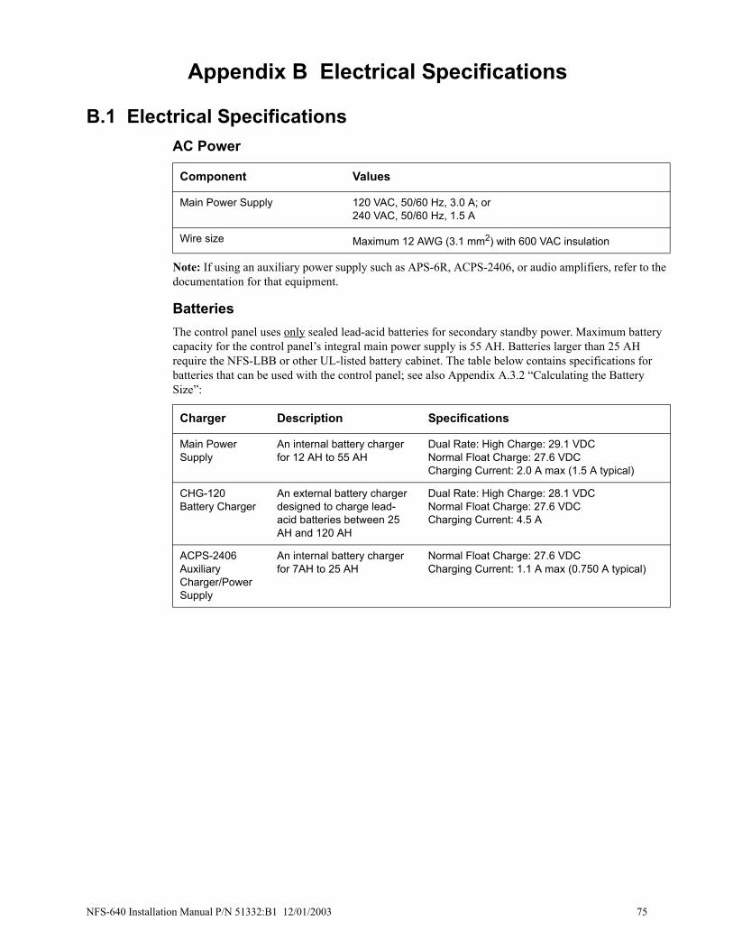
Appendix B Electrical Specifications
B.1 Electrical SpecificationsAC Power
Note: If using an auxiliary power supply such as APS-6R, ACPS-2406, or audio amplifiers, refer to the documentation for that equipment.
BatteriesThe control panel uses only sealed lead-acid batteries for secondary standby power. Maximum battery capacity for the control panel’s integral main power supply is 55 AH. Batteries larger than 25 AH require the NFS-LBB or other UL-listed battery cabinet. The table below contains specifications for batteries that can be used with the control panel; see also Appendix A.3.2 “Calculating the Battery Size”:
Component Values
Main Power Supply 120 VAC, 50/60 Hz, 3.0 A; or 240 VAC, 50/60 Hz, 1.5 A
Wire size Maximum 12 AWG (3.1 mm2) with 600 VAC insulation
Charger Description Specifications
Main Power Supply
An internal battery charger for 12 AH to 55 AH
Dual Rate: High Charge: 29.1 VDCNormal Float Charge: 27.6 VDCCharging Current: 2.0 A max (1.5 A typical)
CHG-120Battery Charger
An external battery charger designed to charge lead-acid batteries between 25 AH and 120 AH
Dual Rate: High Charge: 28.1 VDCNormal Float Charge: 27.6 VDCCharging Current: 4.5 A
ACPS-2406Auxiliary Charger/Power Supply
An internal battery charger for 7AH to 25 AH
Normal Float Charge: 27.6 VDCCharging Current: 1.1 A max (0.750 A typical)
NFS-640 Installation Manual P/N 51332:B1 12/01/2003 75

Electrical Specifications Electrical Specifications
Signaling Line Circuit (SLC)
Notification Appliance Circuits & Releasing Circuits
Output RelaysOutput relays for Alarm, Trouble, Supervisory, and Security are available on power supply terminals TB8, TB9, TB10, and TB11 respectively.
Contact ratings: 2.0 A @ 30 VDC (resistive)
Four-wire Smoke Detector PowerControl Panel terminals TB7 RESET (+) and (–) supply filtered, low-noise power for four-wire smoke detectors. Specifications are:
• Nominal voltage: 24 VDC
• Maximum rated current: 1.25 A DC
• Maximum ripple voltage: 176 mVrms
Refer to the Device Compatibility Document for compatible 24 VDC detectors.
Item Value
Voltage 24 VDC nominal, 27.6 VDC maximum
Maximum length 12,500 ft. (3810 m) per channel (NFPA Style 4) or 10,000 ft. (3048 m) total loop or circuit length (NFPA Style 6 and 7)Note: Refer to Appendix B.2 “Wire Requirements” for limitations.
Maximum current 400 mA peak, 200 mA average (max short circuit; circuit will shut down until short is fixed)
Maximum resistance 50 ohms (supervised and power-limited)
Item Value
Max. wiring voltage drop
2 VDC (except CMX which is 1.2 VDC)
Nominal operating voltage
24 VDC
Current for all external devices connected to the control panel’s power supply
6.0 A in alarm (3 A continuous)
Optional ACPS-2406 Total 6 A in alarm (5 A continuous)
Optional APS-6R Total 6 A in alarm (4 A continuous)
Maximum signaling current/circuit per NAC
2.5 A Note: Some devices have maximum draws less than this; refer to the device’s documentation.
End-of-Line Resistors (ELRs)
Control Panel NACs (TB3, TB4, TB5, TB6): 2.2K, 1/2 wattICM-4RK, ICE-4, VCM-4RK, VCE-4, and DCM-4RK: 4.7K, 1/2 watt (2 watts on 70 Vrms audio)XP5-C, XP5-C, FCM-1 Modules: 47K, 1/2 watt
76 NFS-640 Installation Manual P/N 51332:B1 12/01/2003

Wire Requirements Electrical Specifications
Power Output Control Panel terminals TB7 NONRST (+) and (–) supply one (1) power-limited circuit available to power external devices, such as notification appliances and annunciators.
• Nominal voltage: 24 VDC
• Maximum rated current: 1.25 A DC
• Maximum ripple voltage: 176 mVrms
Refer to the Device Compatibility Document for compatible devices and notification appliances.
Note: The Control Panel provides a total of 6.0 A of power in alarm (3 A in standby), shared by all internal circuitry and external provisions (24 V resettable and non-resettable). For power requirements, refer to the power supply calculation tables in Appendix A.
Operating Power: AC Branch CircuitThe control panel requires connection to a separate dedicated AC branch circuit. Follow these guidelines when connecting the AC branch circuit:
• Label the branch circuit “Fire Alarm”. This must be a separate dedicated AC fire alarm circuit.
• Connect the branch circuit to the line side of the main power feed of the protected premises.
• Do not power other equipment from the fire alarm branch circuit.
• Run the AC branch circuit wire continuously, without any disconnect devices, from the power source to the fire alarm control panel.
• Overcurrent protection for the AC branch circuit must comply with Article 760 of the National Electrical Codes, as well as local codes.
• Use 12 AWG (3.1 mm2) wire with 600 VAC insulation for the AC branch circuit.
Connect the ground terminal (TB2-Earth) to a solid earth ground (a metallic, cold water pipe may be suitable in some installations). This connection is vital to maintaining the control panel's immunity to unwanted transients generated by lightning and electrostatic discharge.
Operating Power: Secondary Power Source (Batteries)The battery charger is current-limited and can recharge sealed lead-acid type batteries. The battery charger shuts off when the control panel is in alarm.
B.2 Wire RequirementsEach type of circuit within the Fire Alarm Control System requires use of a specific wire type to ensure proper circuit operation. The wire gauge of a particular circuit depends on the length of that circuit and the current traveling through it. Use the table below to determine the specific wiring requirements for each circuit.
Compliance with the Federal Communications Commission (FCC) and Canadian Department of Communication regulations on electrical energy radiation requires the following: Use twisted-pair shielded wire for any non-SLC-loop wiring entering or exiting the cabinet that is not enclosed in conduit. Use twisted-pair unshielded wiring for SLC-loop wiring.
Note: If running an SLC in conduit with Notification Appliance Circuits, you can reduce problems by exclusively using electronic sounders (such as the MA/SS-24 Series) instead of more electronically noisy notification appliances (such as electromechanical bells or horns).
NFS-640 Installation Manual P/N 51332:B1 12/01/2003 77

Electrical Specifications Wire Requirements
Note: Lightning arresters required on circuits extending between buildings; 999 meter length maximum to meet UL 1459.
Table 16 Wire Requirements
Circuit Type
Circuit Function Wire Requirements
Distance (feet/meters) Typical Wire Type
SLC(power limited)
Connects to intelligent and addressable modules.
Twisted-unshielded pair, 12 to 18 AWG (3.1 to 0.78 mm2). 50 ohms maximum per length of Style 6 & 7 loops. 50 ohms per branch maximum for Style 4 loop.
12,500/3,8108,000/2,438 4,875/1,486 3,225/983
12 AWG (3.1mm2) 14 AWG (2.00mm2) 16 AWG (1.30mm2) 18 AWG (0.78mm2)
or Untwisted, unshielded wire, in conduit or outside of conduit.
Note: Maximum total capacitance of all SLC wiring (both between conductors and from any conductor to ground) should not exceed 0.5 mircofarads.
1,000/304.8 12 to 18 AWG (3.1 to 0.78 mm2)
EIA-485(power limited)
Connects to LCD-80, ACS modules, or TM-4 Transmitter
Twisted-shielded pair with a characteristic impedance of 120 ohms. 18 AWG (0.78 mm2) minimum.
6,000/1829(max)
16 AWG (1.30mm2)
EIA-232(power limited)
Connects to Printers, CRT, or PC.
Twisted-shielded pair. 18 AWG (0.78 mm2) minimum.
50/15.24 (without modem)
16 AWG (1.30mm2)
IDCInitiating Device Circuit
FMM-1 , FMM-101XP5-M (power limited)
12-18 AWG (3.1 to 0.78 mm2).Maximum circuit resistance is 20 ohms.
12 to 18 AWG (3.1 to 0.78 mm2)
NACNotification Appliance Circuit
XP5-C, FCM-1 (power limited)
12-18 AWG (3.1 to 0.78 mm2). At alarm current level, no more than a 1.2 V drop at the end of the circuit, or sized to provide the minimum rated operating voltage of the appliances used.
To meet 1.2 V drop, or sized to provide the minimum rated operating voltage of the appliances used.
12 to 18 AWG (3.1 to 0.78 mm2)
24 VDC Power Runs(power-limited)
To TM-4 Transmitter, Annunciator and FCM-1 modules
12-18 AWG (3.1 to 0.78 mm2). Size wire so that no more than 1.2 V drop across wire run from supply source to end of any branch.
To meet 1.2 volt drop
12 to 18 AWG (3.1 to 0.78 mm2)
CHG-120 External battery charger
12 AWG (3.1 mm2) in conduit 20/6.1 (max) 12 AWG (3.25mm2)
78 NFS-640 Installation Manual P/N 51332:B1 12/01/2003

Appendix C Compatible Equipment
C.1 UL-Listed EquipmentThese are the most common devices at time of publishing; the most complete list of compatible intelligent SLC loop devices is provided in the SLC Wiring Manual; for conventional non-addressable equipment see the Device Compatibility Document.
Notifier Equipment AA-30 30-Watt Audio Amplifier AA-100 100-Watt Audio Amplifier AA-120 120-Watt Audio Amplifier ABF-1B Annunciator Flush BoxABF-1DB Annunciator Flush Box with DoorABF-2B Annunciator Flush BoxABF-2DB Annunciator Flush Box with DoorABF-4B Annunciator Flush BoxABF-4DB Annunciator Flush Box with DoorABM-16AT Annunciator Blank ModuleABM-32A Annunciator Module BlankABS-1TB Annunciator Surface BoxABS-1B Annunciator Surface BoxABS-2B Annunciator Surface BoxABS-4B Annunciator Surface BoxABS-8R Annunciator Backbox for ACM-8RACM-16AT Annunciator Control ModuleACM-24AT Annunciator Control ModuleACM-32A Annunciator Control ModuleACM-48A Annunciator Control ModuleACM-8R Annunciator Control ModuleACPS-2406 Auxiliary Charger/Power SupplyACT-1 Audio Coupling TransformerACT-2 Audio Coupling TransformerADP-4B Annunciator Dress PanelAEM-16AT Annunciator Expander ModuleAEM-24AT Annunciator Expander ModuleAEM-32A Annunciator Expander ModuleAEM-48A Annunciator Expander ModuleAFM-16A Annunciator Fixed ModuleAFM-16AT Annunciator Fixed ModuleAFM-32A Annunciator Fixed ModuleAKS-1B Annunciator Key SwitchAPJ-1B Annunciator Phone JackAMG-1 Audio Message GeneratorAMG-E Audio Message GeneratorAPS-6R Auxiliary Power SupplyARM-4 Auxiliary Relay ModuleAVL-1 Audio Voice Link (Not ULC-listed)BGX-101L Addressable Manual Pull StationBMP-1 Blank Module PlateBP-4 Battery Dress PlateBX-501 Intelligent Detectors/Sensors BaseB501 Intelligent baseB501BHSounder baseB710LP Intelligent detector baseCAB-4 Series Mounting Hardware (Doors and backboxes are ordered separately. Black unless “R” is added to the P/N)Doors (Add B to the P/N for blank door) DR-A4 A-sized door, 1 row of equipmentDR-B4 B-sized door, 2 rows of equipmentDR-C4 C-sized door, 3 rows of equipmentDR-D4 D-sized door, 4 rows of equipmentBackboxes (For red, add “R” to the P/N)
SBB-A4 A-sized backboxSBB-B4 B-sized backboxSBB-C4 C-sized backboxSBB-D4 D-sized backboxTrim RingsTR-A4 A-sized trim ringTR-B4 B-sized trim ringTR-C4 C-sized trim ringTR-D4 D-sized trim ringCCM-1 Communication Converter ModuleCHS-4L Chassis for voice equipmentCHS-M2 Chassis for 1st row (included in basic equipment package)CHS-4MB Assembly: CHS-4N with MP-1BCHS-4N Chassis for 2nd, 3rd, 4th rows CHG-120 Battery ChargerCMX-1 Addressable Control ModuleCMX-2 Addressable Control ModuleCPU-640 control panel circuit board CPX-551 Ionization Smoke DetectorCPX-751 Intelligent Ionization Smoke DetectorCRE-4 Control Relay ExpanderCRM-4RK Control Relay ModuleCRT-2 Video Display Monitor with KeyboardDCM-4RK Dual Channel ModuleDP-1B Blank Dress Plate DP-DISP Display Dress PlateDPDW-1B Double Well Dress PlateDPSW-1B Single Well Dress PlateDPI-232 Direct Panel Interface FCM-1 NAC ModuleFCPS-24 Field Charger Power SupplyFDX-551Intelligent Thermal SensorFDU-80 Remote Fire Annunciator FFT-7 Fire Fighters TelephoneFFT-7S Fire Fighters TelephoneFHS Fireman's HandsetFMM-1Monitor ModuleFMM-101 Mini Monitor ModuleFSD-751P Photoelectric Duct DetectorFSD-751RP Photoelectric Duct Detector with alarm relayFSD-751PL Low-flow Duct DetectorFSD-751RPL Low-flow Duct Detector with alarm relayDHX-501, DHX-502 Duct DetectorsFSI-751 Ion DetectorAcclimate Plus™ FAPT-751 Combination Photoelectric/Heat DetectorFSH-751HARSH™ Smoke Detector FSL-751 VIEW® Low Profile Laser DetectorFSM-101 Pull Station Monitor ModuleFPJ Fireman's Phone JackFRM-1 Relay ModuleFSP-751 Photo DetectorFSP-751T Photo/Thermal Detector
continued…
NFS-640 Installation Manual P/N 51332:B1 12/01/2003 79

Compatible Equipment UL-Listed Equipment
System Sensor EquipmentA2143-00 End of Line Resistor Assembly
FST-751 Thermal DetectorFST-751R Thermal Detector (rate of rise)FTM-1 Telephone ModuleFZM-1 Monitor ModuleFDM-1 Dual Monitor ModuleICE-4 Indicating Control ExpanderICM-4RK Indicating Control ModuleIPX-751 Advanced Multi-Sensor Intelligent Detector ISO-X Loop Fault Isolator ModuleKDM-2 Keypad/Display UnitL20-300-BX Enclosure; recessed mountL20-310-BX Enclosure; surface mount LCD-80 Liquid Crystal Display ModuleLCD-80TM Terminal Mode LCD AnnunciatorLDM-32 Lamp Driver ModuleLDM-E32 Lamp Driver ModuleLDM-R32 Lamp Driver ModuleLEM-320 Loop Expander ModuleLPX-751 VIEW® Low Profile Laser Detector (CLIP mode)MMX-1 Addressable Monitor ModuleMMX-2 Addressable Monitor ModuleMMX-101 Addressable Mini Monitor ModuleMP-1B Panel Module Dress PlateNBG-12LRA Agent Release-Abort StationNBG-12 Series Manual Pull StationNBG-12LX Addressable Manual Pull StationNCA Network Control Annunciator NCM-F Network Control Module (Fiber)NCM-W Network Control Module (Wire)NCS Network Control StationN-ELR Assortment ELR Pack with Mounting PlateNFS-LBB Battery BoxNFS-LBBR Red Battery BoxP-40 Keltron PrinterP40-KITB Dress plate for Keltron PrinterPRN-4 80-Column PrinterPRN-5 80-Column PrinterPRN-6 80-Column PrinterPS-12120 Battery 12-volt, 12 amp-hourPS-12180 Battery 12-volt, 18 amp-hourPS-12250 Battery 12-volt, 25 amp-hourPS-12550 Battery 12-volt, 55 amp-hourPS-12600 Battery 12-volt, 60 amp-hour
R-120 120 Ohm End-of-Line ResistorR-2.2K 2.2K End-of-Line ResistorR-27K 27K End-of-Line ResistorR-470 470 End-of-Line ResistorR-47K 47K End-of-Line ResistorRA400 Remote AnnunciatorRA400Z Remote Annunciator with diodeRFX Wireless Transmitter (version 2.0 and higher): SDRF-751 Wireless Photo/Thermal Smoke Detector; 5817CB Wireless Monitor ModuleRPJ-1 Fireman's Phone JackRPT-485F EIA-485 Repeater (Fiber)RPT-485W EIA-485 Repeater (Wire)RPT-485WF EIA-485 Repeater (Wire/Fiber)RM-1 Remote MicrophoneRM-1SA Remote MicrophoneSCS-8, SCE-8 Smoke Control StationSCS-8L, SCE-8L Smoke Control Lamp DriverSDX-551 Intelligent Photoelectric DetectorSDX-751 Intelligent Photoelectric DetectorSTS-1 Security Tamper Switch TM-4 Transmitter ModuleUDACT Universal Digital Alarm Communicator TransmitterUZC-256 Universal Zone CoderVCE-4 Voice Control ExpanderVCM-4RK Voice Control ModuleVeriFire™ Tools Upload/Download SoftwareVP-2B 2” Filler Dress PlateXP5-C Transponder Control ModuleXP5-M Transponder Monitor ModuleXPC-8 Transponder Control ModuleXPDP Transponder Dress PanelXPIQ Quad Intelligent Audio TransponderXPM-8 Transponder Monitor ModuleXPM-8L Transponder Monitor ModuleXPP-1 Transponder ProcessorXPR-8 Transponder Relay ModuleXP6-C Supervised Control Module XP6-R Six Relay Control Module XP6-MA Six Zone Interface Module XP10-M Ten Input Monitor Module
80 NFS-640 Installation Manual P/N 51332:B1 12/01/2003

US Coast Guard & Lloyd’s Register Compatible Equipment
C.2 US Coast Guard & Lloyd’s Register AA-30 Audio AmplifierAA-100 Audio AmplifierABM-16AT Annunciator Blank ModuleABM-32A Annunciator Blank ModuleACM-16AT Annunciator Control ModuleACM-24AT Annunciator Control ModuleACM-32A Annunciator Control ModuleACM-48A Annunciator Control ModuleADP-4 Annunciator Dress PanelAEM-16AT Annunciator Expander ModuleAEM-24AT Annunciator Expander ModuleAEM-32A Annunciator Expander ModuleAEM-48A Annunciator Expander ModuleAMG-1 Audio Message GeneratorARM-4 Auxiliary Relay ModuleBMP-1 Blank Module PlateBP-4 Battery Dress PlateB224RB Intelligent Relay BaseB224BI Intelligent Isolator BaseB501 Intelligent BaseB501BH Sounder base with B501 baseB501BHT B501BH with Temporal sounderB710LP Intelligent Detector BaseCAB-4 Series Backboxes
(Black unless "R" is added to part number)SBB-A4 A size backboxSBB-B4 B size backbox
CHS-4L Chassis for voice systemCHM-M2 Chassis for 1st row (included in basic equipment
package)CHS-4MB Chassis for second rowCRE-4 Control Relay ExpanderCRM-4RK Control relay ModuleDP-1B Blank Dress PanelDP-DISP Display Dress PanelDPDW-1B Double Well Dress PlateDPSW-1B Single Well Dress PlateFCM-1 Addressable Control ModuleFMM-1 Addressable Monitor ModuleFMM-101 Addressable Mini Monitor ModuleFSD-751P Addressable Photo Duct DetectorFSI-751 Addressable Ion DetectorFSI-851 Addressable Ion DetectorAcclimate Plus FAPT-751 Addressable Combination Photo/
Heat DetectorFSM-101 Addressable Pull Station ModuleFRM-1 Addressable Relay ModuleFSP-751 Addressable Photo DetectorFSP-851 Addressable Photo Detector FSL-751 Addressable Laser DetectorFSP-751T Addressable Photo / Thermal DetectorFSP-851T Addressable Photo / Thermal Detector FST-751 Addressable Heat DetectorFST-851 Addressable Heat DetectorFST-751R Addressable Heat with Rate of RiseFST-851R Addressable Heat with Rate of RiseFST-851H Addressable High HeatICE-4 Indicating Control ExpanderICM-4RK Indicating Control ModuleISO-X Loop Fault Isolator ModuleKDM-2 Keypad/Display UnitLEM-320 Loop Expander ModuleMP-1B Panel Module Dress PlateNBG-12LX Addressable Pull StationNBG-12S Single Action Manual Pull StationNBG-12 Dual Action Pull Station Hex LockNBG-12L Dual Action Pull Station with Key LockNBG-12SP Spanish LabelingNBG-12LRA Agent Release-Abort StationNCA Network Communication AnnunciatorNCM-F Network Control Module (Fiber)NCM-W Network Control Module (WIRE)PS-12120 Battery 12 volt 12 Amp-HourPS-12180 Battery 12 volt 18 Amp-HourPS-12250 Battery 12 volt 25 Amp-HourPS-12550 Battery 12 volt 55 Amp-Hour
R-120 120 Ohm End of Line ResistorR-2.2K 2.2K Ohm End of Line ResistorR-27K 27K Ohm End of Line ResistorR-470 470 Ohm End of Line ResistorR-47K 47K Ohm End of Line ResistorTM-4 Transmitter Module
SYSTEM SENSOR HORNS/STROBES/SPEAKERSH24 (W) 24VDC Horn Red (White)H24K (W) 24VDC Horn Weather proof Red OnlyMA/SS-24D 24VDC Electronic Sounder/StrobeP2415(W) 24VDC 15cd Horn/Strobe Red (White)P241575 (W) 24VDC 15/75cd Horn/Strobe Red (White)P2430 (W) 24VDC 330cd Horn/Strobe Red (White)P24110 (W) 24VDC 110cd Horn/Strobe Red (White)P241575K 24VDC 15/75cd Horn/Strobe Weather proof Red
OnlyP2475K 24VDC 75cd Horn/Strobe Weather proof Red OnlyP24110K 24VDC 110cd Horn/Strobe Weather proof Red OnlyP241575P(W) 24VDC 15/75cd Horn/Strobe No Lettering Red
(White)P241575AG 24VDC 15/75cd Horn/Strobe Agent Red OnlyP241575EV 24VDC 15/75cd Horn/Strobe Evacuation Red
OnlyS2415 (W) 24VDC 15cd Strobe Red (White)S241575 (W) 24VDC 15/75cd Strobe Red (White)S2430 (W) 24VDC 30cd Strobe Red (White)S2475 (W) 24VDC 75cd Strobe Red (White)S24110 (W) 24VDC 110cd Strobe Red (White)S241575K 24VDC 15/75cd Strobe Weather proof Red OnlyS2475K 24VDc 75cd Strobe Weather proof Red OnlyS24110K 24VDC 110cd Strobe Weather proof Red OnlyS241575P (W) 24VDC 15/75cd Strobe No Lettering Red
(White)S241575AG 24VDC 15/75cd Strobe Agent Red OnlyS241575EV 24VDC 15/75cd Strobe Evacuation Red OnlySP2R2415 24VDC 15cd Speaker/Strobe RedSP2W2415 24VDC 15cd Speaker/Strobe WhiteSP2R241575 24VDC 15/75cd Speaker Strobe RedSP2W241575 24VDC 15/75cd Speaker/Strobe WhiteSP2R2430 24VDC 30cd Speaker/Strobe RedSP2W2430 24VDC 30cd Speaker Strobe WhiteSP2R2475 24VDC 75cd Speaker/Strobe RedSP2W2475 24VDC 75cd Speaker/Strobe WhiteSP2R24110 24VDC 110cd Speaker/Strobe RedSP2W24110 24VDC 110cd Speaker/Strobe WhiteSP201W Square White Wall mount SpeakerSP201R Square Red Wall mount Speaker
MOUNTING BOXESWBB Weather proof Backbox from System SensorWP-10 Weather proof Backbox from NotifierBBS-SP2R Surface mount Backbox Skirt RedBBS-SP2W Surface mount Backbox Skirt White
SURGE SUPPRESORS29149 Ferrite Bead for AC input3VR3 EMI Filter from CORCOM for AC input
NFS-640 Installation Manual P/N 51332:B1 12/01/2003 81

Notes
82 NFS-640 Installation Manual P/N 51332:B1 12/01/2003
Appendix D Canadian Applications
D.1 Standalone ApplicationD.1.1 NFS-640 with KDM-2 If using KDM-2 as the primary display for NFS-640, an ACS series annunciator must be mounted adjacent to the panel or within NFS-640 enclosure.
D.1.2 NFS-640 with NCA Network Control Annunciator (NCA) with 640-character, multi-line display complies with ULC requirements when used as the primary display for NFS-640.
D.2 Local Network ApplicationTo meet ULC requirements, the network’s Manual Controls may only be operated from one location at any given time.
When panels networked (using NCM Network Control Modules), employ AKS-1 Key Switch on each panel’s Primary Annunciator to enable its functions. NCA may be a Primary Annunciator when AKS-1B is installed. Refer to the NCA Manual for more information.
An NCA or Network Control Station (NCS) may be employed as a Display and Control Center. In the event that communication fails between the panels and the Control Center, the panels will continue to function in local/standalone mode.
D.3 Automatic Alarm Signal SilenceIf selecting this feature for a system requiring annunciators, consult the Authority Having Jurisdiction.
D.4 Annunciator Applications 1. In Canada, the ACM series annunciator modules must be used to annunciate the fire alarm input
points/zones only, if no multi-line sequential display is installed.
2. For Canadian applications, the following LED colors must be employed:
• Red must be used to indicate active alarm inputs.
• Yellow must be used to indicate supervisory, burglary or trouble signals.
• Green must be used to indicate the presence of power or an activated output.
D.5 Releasing DevicesSupervision for shorts is required; use REL devices and type code REL CKT ULC.(With on-board NACs, use REL-2.2K; with FCM-1 modules use REL-47K. Refer to Section 4.5 “Releasing Applications” for details.
NFS-640 Installation Manual P/N 51332:B1 12/01/2003 83

Notes
84 NFS-640 Installation Manual P/N 51332:B1 12/01/2003

Index
IndexNumerics24 VDC, see DC Power 39
AAC, see Power 38Acceptance Test 67ACM-16AT 22ACM-24AT 21ACM-32A 22ACM-48A 22ACM-8R 42
Overview 21ACPS-2406
Overview 17ACS, see Annunciators 21Addressable Modules
Overview 19, 20AEM-16AT 22AEM-24AT
Overview 22AEM-32A 22AEM-48A 22AFM-16AT
Overview 22AFM-32A
Overview 23Agent Release-Abort Station 66Alarm relays, see Form-C relays 40Annunciator Fixed Modules
Overview 22Annunciators 21
Overview 21APS-6R 17
See Auxiliary Power 39ARM-4
Installation steps 48non-power-limited circuits 42Overview 24Stand-off and Terminal Locations 49
Audio Amplifiers, see Voice Alarm System 25
Audio Message Generator, see Voice Alarm System 25
Auxiliary Relay Module, see ARM-4 48
BB224BI 19Backboxes
Battery boxes 17Backup-alarm switches 41Basic Equipment Packages 12Batteries
Battery Boxes 17Battery calculations 69, 71, 72, 73, 74Battery Checks and Maintenance 68Battery specifications 75Installation 38Overview 17
Blank modules 16
CCabinets
Mounting 29Overview 16
California code 47
Canadian Applications 83central receiving unit, also see UDACT
manual 60Chassis 16, 36, 48CHG-120
Overview 18Circuit Board, see CPU 13Compatible Equipment 79Components 14, 15Control Modules: Overview 20Control Panel Circuit Board 13, 14, 15CPU 13
drawing 13, 14, 15Installation steps 31
CPU-640 (120V operation) 12CPU-640E (240V operation) 12CRE-4
non-power-limited circuits 42Overview 24
CRM-4RK 43Connections 47CRM-4RK/CRE-4 48non-power-limited circuits 42
CRTs 55CRT/PRN combination 55CRT-2 Configuration 52CRT-2 Function Keys and
parameters 54CRT-2 Overview 23Installation 50–55
DD35 on ICM-4RK 47DC, see Power 38Detectors
Detector bases 19listing 18Overview 18
Display TerminalOverview 23
Dress Panels 16Dual Channel Module
see also Voice Alarm System; see also Voice Alarm System Manual 25
EElectrical connections 37Electrical Specifications 75Expander boards, see Panel Circuit
Modules-Expander Board Modules 43
FFCM-1 65FCPS-24
Overview 18Fire Fighters Telephone, see Voice
Alarm System 25Fire/Security Applications 59–62FlashScan®
Overview 18Form-C relays 20, 21, 24, 40, 47, 48, 76Four-wire Smoke Detector
Specifications 76FST-751 19
IICM-4RK 43
Connections 45Field-wiring 46Jumpers 45Overview 24Resistors 47
InstallationChecklist 28Preparation 27
JJumper locations 14, 15
ICM-4RK 45
KKDM-2
Installation steps 31Keltron printer 51
Overview 23
LLCD-80
Overview 18LDM-32
Overview 21LDM-R32
non-power-limited circuits 42Overview 21
LED locations 15LEM-320
Overview 17lockout 67Loop Expander Module
Installation steps 34
MMain power supply 13Maintenance 67microcontroller failure 41Monitor Modules
Overview 20Mounting
LEM 34Panel Circuit Modules 44
Multi-Input/Output Modules 20
NNAC 63, 64NACs
Backup option 41NAC Connections 40NAC/Releasing Circuits 64Releasing circuits 40Releasing functions 41Specifications 76
NBG-12LRA 66NBG-12LX 20NCA 32, 33
also see Primary display 12Overview 17
NCM-W/FOverview 17
Networking 35NFPA Applications
NFS-640 Installation Manual P/N 51332:B1 12/01/2003 85

Index
NFPA 72 Central or Remote Station Fire Alarm System 58
Overview 57Nonpower-limited circuits
UL wiring requirements 42Notification Appliance Circuits, see
NACs
OOperating Power 77Operational Checks 67Output relays
Connections 20, 21, 24, 40, 47, 48, 76Specifications 76
PPanel Circuit Modules
Expander Board Module 43Expander Board Modules 43Installation steps 35, 43Overview and complete list 24Ribbon cables 44see also ICM-4RK, ICE-4, CRM-
4RK, CRE-4, VCM-4RK, DCM-4RK, VCE-4 43
Periodic Testing 67Power
AC Power Checklist 38AC power connections 37, 38AC specifications 75Auxiliary Power 39Battery connections 38DC Power Connections 39DC power connections 38Installation steps 37Power specifications 37, 77
Power supply calculations 69, 71, 72, 73, 74
Power-limited Wiring Requirements 42Printers 51, 55
Installation 50–55Overview 23PRN 23
PRN/CRT combination 55PRN-5 50Proprietary Security Alarm Applications
Wiring 62Protected Premises Unit 58
QQuad Intelligent Audio Transponder
Overview 20
RRA400Z 19Related Documentation 8Relays, see Form-C relays 40Releasing Circuit Connections 40Releasing Circuits
Connections 40Releasing Applications 63–66Releasing Applications, Canada 83Specifications 76
Releasing DeviceConnections 64FCM-1 Connections 65
Remote Microphone, see Voice Alarm System 26
Resistor locations
ICM-4RK 47
SS5000 modules, see Panel Circuit
Modules 24Security relays, see Form-C relays 40security switch, wiring 62Security Tamper Switch 60Service 67Signaling Line Circuit, see SLC 18SLC 18, 34
see also SLC Wiring Manual 56specifications 76
Specifications 76Stacker-connector 34Stand-off Lengths 31STS-1 62Supervisory and Security contacts
configuring as Alarm contacts 40Supervisory relays, see Form-C
relays 40Supplemental Documentation 8Switches
Backup-alarm 41switch locations 14, 15
SystemFeatures 11Limitations 12Options 12
System current draws 69, 71, 72, 73, 74System Description 11
TTCC-1B, see Voice Alarm System 25Terminal block locations 14, 15Testing 67TM-4
Overview 17see Transmitter Module TM-4 41
TranspondersOverview 20
Trouble relays, see Form-C relays 40
UUDACT
Overview 17UL nonpower-limited wiring
requirements 42UL Requirements 42UZC-256
Overview 17
VVCC-1B, see Voice Alarm System 25VeriFire 54Voice Alarm System
Overview 25, 26see also Voice Alarm System
Manual 25Voice Control Module, see Voice Alarm
System 25VTCC-1B, see Voice Alarm System 25
WWiring
Proprietary Security Alarm Applications 62
Wire Requirements 77
XXP5-C 20XP5-M 20, 62XP6-C, XP6-R, XP10-M, XP6-MA 20XPIQ
Overview 20
86 NFS-640 Installation Manual P/N 51332:B1 12/01/2003

Limited Warranty
NOTIFIER® warrants its products to be free from defects in materialsand workmanship for eighteen (18) months from the date ofmanufacture, under normal use and service. Products are datestamped at time of manufacture. The sole and exclusive obligation ofNOTIFIER® is to repair or replace, at its option, free of charge forparts and labor, any part which is defective in materials orworkmanship under normal use and service. For products not underNOTIFIER® manufacturing date-stamp control, the warranty iseighteen (18) months from date of original purchase by NOTIFIER®’sdistributor unless the installation instructions or catalog sets forth ashorter period, in which case the shorter period shall apply. Thiswarranty is void if the product is altered, repaired or serviced byanyone other than NOTIFIER® or its authorized distributors or if thereis a failure to maintain the products and systems in which they operatein a proper and workable manner. In case of defect, secure a ReturnMaterial Authorization form from our customer service department.Return product, transportation prepaid, to NOTIFIER®, 12 ClintonvilleRoad, Northford, Connecticut 06472-1653.
This writing constitutes the only warranty made by NOTIFIER® withrespect to its products. NOTIFIER® does not represent that itsproducts will prevent any loss by fire or otherwise, or that its productswill in all cases provide the protection for which they are installed orintended. Buyer acknowledges that NOTIFIER® is not an insurer andassumes no risk for loss or damages or the cost of anyinconvenience, transportation, damage, misuse, abuse, accident orsimilar incident.
NOTIFIER® GIVES NO WARRANTY, EXPRESSED OR IMPLIED,OF MERCHANTABILITY, FITNESS FOR ANY PARTICULARPURPOSE, OR OTHERWISE WHICH EXTEND BEYOND THEDESCRIPTION ON THE FACE HEREOF. UNDER NOCIRCUMSTANCES SHALL NOTIFIER® BE LIABLE FOR ANY LOSSOF OR DAMAGE TO PROPERTY, DIRECT, INCIDENTAL ORCONSEQUENTIAL, ARISING OUT OF THE USE OF, OR INABILITYTO USE NOTIFIER® PRODUCTS. FURTHERMORE, NOTIFIER®SHALL NOT BE LIABLE FOR ANY PERSONAL INJURY OR DEATHWHICH MAY ARISE IN THE COURSE OF, OR AS A RESULT OF,PERSONAL, COMMERCIAL OR INDUSTRIAL USE OF ITSPRODUCTS.
This warranty replaces all previous warranties and is the onlywarranty made by NOTIFIER®. No increase or alteration, written orverbal, of the obligation of this warranty is authorized.
"NOTIFIER" is a registered trademark.Warn-NL-10-2001.fm
NFS-640 Installation Manual P/N 51332:B1 12/01/2003 87

World Headquarters12 Clintonville Road
Northford, CT 06472-1653 USA203-484-7161
fax 203-484-7118
www.notifier.com
NOTIFIER is a company.