finkbeiner
DESCRIPTION
Vehicle LiftTRANSCRIPT

Walter Finkbeiner GmbH, Alte Poststrasse 9 / 11, D - 72250 Freudenstadt
OPERATOR’S MANUAL FOR MOBILE COLUMN LIFT TYPE EHB
page 1
M A N U A L
F O R
M O B I L E C O L U M N L I F T
E H B 7 0 7 V 1 1 - 4 E H B 7 0 7 V 1 1 - 6
SERIAL-NO.:
<<S/N>>
DATE OF MANUFACTURE/ DELIVERY:
<<Datum>>
CUSTOMER: <<Name>>
MANUFACTURER: FINKBEINER - Lifting Systems
Walter Finkbeiner GmbH Alte Poststrasse 9 / 11 D-72250 Freudenstadt / Germany Tel.: +49-7441-4031 Fax: +49-7441-87778 E-mail: [email protected] http://www.finkbeiner-lifts.com

Walter Finkbeiner GmbH, Alte Poststrasse 9 / 11, D - 72250 Freudenstadt
OPERATOR’S MANUAL FOR MOBILE COLUMN LIFT TYPE EHB
page 2
INDEX
Index ..........................................................
................................... 2
Set-Up Instructions .....................................
................................... 3
Register for mobile column lift………………
................................... 5
Safety Instructions ......................................
................................... 7
Short Operating Instructions ...................…
................................... 8
Detailed Operating Instructions ..................
................................... 9
Maintenance and Service Instructions ........ ................................... 13
Trouble Shooting ........................................ ................................... 16
Emergency Lowering Instructions …........... ................................... 19
General drawing of column ……………….. ………………………… 20
Electric Components .................................. ................................... 21
Wiring Diagram – Master column ............... ................................... 22
Wiring Diagram – Slave column ................ ................................... 24
Hydraulic Circuit Diagram with Parts List ... ................................... 26
Mechanical Parts ........................................ ................................... 27
Conformity Certificate of Manufacturer …... ................................... 28
Test Certificate ........................................... ................................... 29
CE Certificate ............................................. ................................... 30
Appendix, inspection and testing …………. ………………………… 31
Certificate for regualar tests ……………….. ………………………… 32

Walter Finkbeiner GmbH, Alte Poststrasse 9 / 11, D - 72250 Freudenstadt
OPERATOR’S MANUAL FOR MOBILE COLUMN LIFT TYPE EHB
page 3
SET – UP INSTRUCTIONS
Installer: Please follow these instructions to ensure a satisfactory set-up and operation of the lift SET-UP OF COLUMN 1. Transport: Columns are shipped in the vertical position. Do not tilt
them! 2. Unloading:
• Column package should be lifted using a fork truck under the bottom wooden cross beams.
• You also can hook into hole on steel plate to lift the individual column by chains.
• Carefully unload the lift. Do not get heavy shocks onto the lift. fig.1
3. Remove packing and protective wrapping. 4. Adjust rear wheel jack at each column:
• Remove fixing of rubber wheel. Screw-down M20-bolt clockwise to raise the column. Ground clearance is determined by how far the bolt is turned. If column is loaded it will automatically be lowered by spring compression. Adjust ground clearance as minimum as necessary in order to prevent cables to go underneath of column’s frame. Always take care column will lower totally to the ground when being loaded.
fig.2
5. Check oil level in oil tank of each column: Remove cover panel of power unit. Remove oil gage and check oil level. If necessary, fill with hydraulic oil ISO32 (SAE10). (See Maintenance and Service Instructions).
ELECTRICAL SUPPLY IMPORTANT: This lift is wired and adjusted to operate at 400 volts/50Hz If this does not match your facilites voltage, STOP; change motor wiring and transformer jumpers as shown. Incorrect voltages may cause internal, irreparable electrical damage.
IMPORTANT: Use a separate circuit for each lift. Size circuit breaker, receptable and plug based on the chart below. Wiring shall comply with all local electrical codes.
Electrical Requirements Lift Model Electrical Service Fuses on Site EHB707-4 400V, 3Ph., 50Hz. 16 Amp. EHB707-6 400V, 3Ph., 50Hz. 16 Amp
Voltage: 400V, 3 ph., PE Ground / clockwise rotation of motor required! Phases, power cores L1 (black), L2 (brown), L3 (blue), Ground (yellow green) Frequency: 50 Hz.
IMPORTANT: If facilities voltage is not listed, STOP; consult the factory. Other voltages may cause internal, irreparable electrical damage. Select the appropriate receptacle and install in a suitable wall-mounted box near the lift’s operation area. Install plug on lift’s power cord.

Walter Finkbeiner GmbH, Alte Poststrasse 9 / 11, D - 72250 Freudenstadt
OPERATOR’S MANUAL FOR MOBILE COLUMN LIFT TYPE EHB
page 4
ELECTRICAL CONNECTION NOTE: The lift may only be connected with a appropriate power supply outlet which is installed as prescribed and earthed as per local safety regulations and which is incorporated in a protective circuit. Electrical connections have to be done by an expert.
1. Connect interconnect cables from column to column, in a circuit around the vehicle. See fig.3. Lock each socket with the plug locks provided. Plug power cord on master column into the appropriate power supply outlet.
2. Before operating the lift it should be checked for functionality first, without load. When operating the lift, regard the Detailed Operation Instruction enclosed.
3. If lift does not begin to raise after 10 seconds of depressing the UP button, you need to stop and check motor rotation. Clockwise rotation of motor is required. Rotation of the motor can be changed. Disconnect the power cord from the power supply outlet. Remove the plug on power cord and rewire the plug by changing two phases (L1/L2). NOTE: Do not change the wiring within the lift system or control panel. The motor rotation may be different if the lift is operated at a different location.
CONNECTING OF COLUMNS
Master Column (can be positioned at any convenient location)
Master Column (can be positioned at any convenient location)
fig.3

Walter Finkbeiner GmbH, Alte Poststrasse 9 / 11, D - 72250 Freudenstadt
OPERATOR’S MANUAL FOR MOBILE COLUMN LIFT TYPE EHB
page 5
REGISTER FOR MOBILE COLUMN LIFT 1. GENERAL INFORMATION manufacturer: FINKBEINER-Lifting Systems
Walter Finkbeiner GmbH Alte Poststrasse 9 / 11 D-72250 Freudenstadt / Germany decription: Portable, electro-hydraulic lifting columns to lift vehicles at the tires type: EHB707V11-4 (1 master / 3 slave columns, adjustable support
forks) EHB707V11-6 (1 master / 5 slave columns, adjustable support
forks) lifting capacity: EHB707V11-4: 4 x 7200 kgs = 28800 kgs EHB707V11-6: 6 x 7200 kgs = 43200 kgs
arranged for working underneath load pick-up attachment - yes 2. ADDITIONAL GENERAL INFORMATION admissible static lateral pressure at working platform: 1000 N admissible dynamic pressure on the windward side of the lifted vehicle: 100 N/m2 3. CONTROL Integrated master/slave control panels at lifting columns. Standard control of master column suitable for common operation of up to 6 columns. Synchronizing compensation with safety control system, tolerance for control height difference between column is approx. 3 mm. Control mounted on printed circuit boards, plugable and easy to exchange. 4. LIFTING / LOWERING SPEED lifting respective lowering speed: approx. 0.80 m/min = 0,0133 m/sec. 5. DRIVE, ELECTRO-HYDRAULIC electric motor 1.1KW, 400V, 3 Ph/PE, 50 Hz hydraulic pump gear pump 2.2 ccm/rev. operating pressure = 240 bar, pressure relief valve = 240 bar admissible range of temperature of hydraulic oil: -10° to + 50° C 6. SUPPORTING MEANS hydraulic cylinder, directly and single acting, D 90/70 mm, stroke = 1700 mm 7. LOAD PICK-UP ATTACHMENT EHB707V11: adjustable support forks for tire sizes from 155R13 to 12.00-20 resp. 155R13 to 13R22.5, tire diameters from 550 to 1140 mm, length 300 mm 8. COLUMN dimensions: 1160 x 1100 x 2250 mm weight: 580 kgs
Walter Finkbeiner GmbH, Alte Poststrasse 9 / 11, D - 72250 Freudenstadt
OPERATOR’S MANUAL FOR MOBILE COLUMN LIFT TYPE EHB
page 6
9. ELECTRIC EQUIPMENT operating voltage: 3 x 400 V, 50 Hz /PE control voltage: 24 V DC type of protection: IP 65, protection class 1. admissible range of temperature for control: -10° to +60° C lifting equipment suitable for use in: - open air - wet and humid rooms IMPORTANT: lifting equipment must not be used at explosion proof areas! 10. PAINT COAT final coat (powder paint) RAL 2004, orange - lift column RAL 7043, grey - lift carriage 11. SAFETY EQUIPMENT ELECTRICS - synchronism-regulation for absolut synchron run of all columns - safety control system for supervision of all operating functions - lockable main switch - emergency stop at each column - control voltage 24 V DC - automatic motor protection at each column HYDRAULICS - overload protection by pressure relief valve - load securing by check valve MECHANICS - automatical mechanical locking device - overload protection of travelling device by spring deflection, with adjustable ground
clearance - locking frame at rear wheel 12. SAFETY REGULATIONS The lift has been designed according to following safety instructions: - UVV-VBG14 und EN1493 - 89/392/EWG in connection with 91/368/EWG and 93/44/EWG - 73/23/EWG EG-low voltage safety regulations - 89/336/EWG EG-regulation of electromagnetic compliance EMV CE-conformity certificate of the manufacturer is enclosed to this manual. The appropriate local safety regulation of the respective country in which the lift is used are valid furtheron. Within the EU following regulations for the user are valid: - 89/391/EWG - 89/654/EWG - 89/655/EWG - 89/656/EWG - 92/58/ EWG WALTER FINKBEINER GMBH D – 72550 FREUDENSTADT

Walter Finkbeiner GmbH, Alte Poststrasse 9 / 11, D - 72250 Freudenstadt
OPERATOR’S MANUAL FOR MOBILE COLUMN LIFT TYPE EHB
page 7
SAFETY INSTRUCTIONS • Daily inspect your lift. Never operate it if malfunctions or if it has broken or damaged
parts. • Use only qualified lift service personnel and genuine FINKBEINER parts to make
repairs. • Thoroughly train all employees in use and care of lift, using manufacturer’s
instructions supplied with the lift. • Never allow unauthorized or untrained persons to position vehicle / lift or operate lift. • Prohibit unauthorized persons from being in shop area while lift is in use. • Do not permit anyone on lift or inside vehicle when it is either being raised or lowered. • Always keep area around lift free of tools, debris, grease and oil. • Never overload lift. Capacity of lift is shown on nameplate affixed to the lift. • Do not hit or run over lift forks or base.This could damage lift or vehicle. Before driving
vehicle into area, position lift units to provide unobstructed entrance onto lift area. • Do not block, open or override self-closing lift controls, they are designed to return to
the OFF or neutral position when released. • Remain clear of lift and vehicle when lowering. • Avoid excessive rocking of vehicle while on lift. • Clear area if vehicle is in danger of falling. • Position lift columns to provide an unobstructed exit before removing vehicle from lift
area. • Do not perform any maintenance on the control panels until the power has been shut
off to the lift.

Walter Finkbeiner GmbH, Alte Poststrasse 9 / 11, D - 72250 Freudenstadt
OPERATOR’S MANUAL FOR MOBILE COLUMN LIFT TYPE EHB
page 8
SHORT OPERATING INSTRUCTIONS INSTALLATION • Locate lift columns on a level and sufficent load-bearing surface. • Lift columns should be placed at the tires advised by the vehicle’s manufacturer,
equidistant from tire‘s centerline, 2 lifting columns at one common axle. • Position the support forks of lift as far as possible under the vehicle tires to fully contact
the tires. • Sufficient safety clearance between vehicle body and lift column has to be maintained. • Pay attention to required size of tyres 155R13 to 13R22.5 (diameter 550-1140 mm).
Adjust both forks as narrow as possible underneath the tire. Both forks must be equidistant from lift’s centerline. Always secure forks with pin.
• Plug together lift columns by interconnect cables from column to column, in a circuit around the vehicle. Plug into the power supply outlet.
OPERATION - PERFORMANCE • Operation by persons only who are 18 years of age and who have been instructed in
the handling of the lift. • Switch-on main switch at at Master Column. Press CONTROL ON - button. The green
CONTROL-ON lamp illuminates. • Select operation mode SINGLE/ALL at Master Column. The red lamp is illuminated at
SINGLE. • The lift can be raised / lowered directly at each column by pressing UP / DOWN, with
SINGLE and ALL-mode. • Operation ALL is only possible when the green lamp (common cycle) is illuminated. For
that all yellow or all blue lamps of the columns must be illuminated. • If no green lamp (common cycle) is illuminated adjust each column in SINGLE-mode. OPERATION • Never overload the lift. Capacity is maximum 7200 kgs per column. • Load vehicle on lift carefully. Raise lift until tires are clear from the floor. Check secure
and correct contact of support forks with vehicle tires. • Inclined raising / lowering of the vehicle is not allowed. • Regard not to stand under the lift or under the load during raising / lowering movement
and observe sufficient safety clearance towards the moving parts of the lift. • Pay attention that the movement area of the lift is free from any obstacles and that no
persons stay therein. • Constantly supervise the lift and the lifted vehicle and stop operation immediately by
pressing the emergency-stop button if anything is working not correctly. • After finishing lifting or lowering, main switch has to be switched-off and locked against
unauthorised use. • The Detailed Operating and Maintenance Instructions have to be observed (see lift
manual).

Walter Finkbeiner GmbH, Alte Poststrasse 9 / 11, D - 72250 Freudenstadt
OPERATOR’S MANUAL FOR MOBILE COLUMN LIFT TYPE EHB
page 9
DETAILED OPERATING AND MAINTENANCE INSTRUCTIONS
COMMISSIONING RANGE OF APPLICATION • The Mobile Column Lift is suitable only for lifting commercial vehicles at the tires
respective with additional traverses directly at the chassis. • Do not exceed admissible capacity of the lift. • Do not use the lift in fire hazard rooms nor in explosion-proof areas. INSTALLATION • Regard enclosed Set-Up Instructions. • Locate the lift columns vertically on a smooth, level and sufficient load-bearing surface.
Admissable slope of ground is 1°. For ground surface preferably concrete of quality minimum B20 is required. Maximal pressure of wheels on floor = 200 kgs/cm2.
• Master column with power supply cord has to be located towards the vehicle at any location. All other slave columns are interchangable. See fig.3. Maximum 5 slave columns can be connected with 1 master column.
• Lift columns have to be located at the tires advised by vehicles’s manufacturer to be lifted, exactly towards the centerline of the tire, 2 lift columns at one common axle.
• Move in lift columns as far as possible under the vehicle tires. The front face of the support carriage should touch the outside of the tire.
fig.4 • For lifting of vehicles with double axles, please see instructions of the vehicle`s
manufacturer. • Lifting of vehicles at the frame with additional traverses only at safe and advised lifting
points. • Sufficient safety clearance between the vehicle body and the lift column at the top has
to be maintained. • Mind sufficient clearance of the front face of the support carriage to the vehicle`s tire
rims. • EHB707V11 with adjustable forks: Pay attention to required size of tires 155R13 to
13R22.5 (diameter 550-1140 mm). Adjust both forks as narrow as possible underneath the tire. Both forks must be equidistant from lift’s centerline. Always secure forks with pin. No adaptors required.
• Plug together lift columns by interconnect cables from column to column, in a circuit around the vehicle. Lock plugs with the socket locks provided. Plug power cord with plug into appropriate power supply outlet. IMPORTANT: The outlet must be wired with the correct polarity. Clockwise rotation of motor is required.
• Keep feet clear of lift frame while the travelling device of column is lowered. REQUIREMENTS FOR OPERATING PERSONS Operation by persons only who are 18 years of age and who have been instructed in the handling of the lift. PRE-OPERATIONAL CHECKS Before commencing operations, the lift operator or other compentent person shall carry out routine checks in accordance with the operation instructions, which shall be sufficient to ensure the safe operation of the lift.
Walter Finkbeiner GmbH, Alte Poststrasse 9 / 11, D - 72250 Freudenstadt
OPERATOR’S MANUAL FOR MOBILE COLUMN LIFT TYPE EHB
page 10
PERFORMANCE OPERATION • Switch-on main switch on Master Column control panel. Press CONTROL ON - push
button, green CONTROL-ON lamp illuminates. • Select operation mode at SELECTOR SWITCH at Master Column: SINGLE / ALL. • At SINGLE mode, raising and lowering can be performed from any column by pressing
the respective push-button UP / DOWN. When operating several lifting columns simultaneously, no different ways of movement are possible at one time. Only the movement of the push-button, that was pressed first, will be carried out.
• Operation mode is shown by red blinking lamp at each column: ON = SINGLE, OFF = ALL operation.
• Operation mode SINGLE / ALL is possible from any column, UP / DOWN. • EMERGENY-STOP push button at each column switches off immediately the complete
lift. NOTE: when the button is pushed it is locked in the off-position. For re-operating the lift release EMERGENY STOP push-buttons.
• Operation mode ALL is only possible when the green lamp (COMMON CYCLE) is illuminated. For that all yellow or all blue lamps of the columns must be illuminated.
• If no green lamp (COMMON CYCLE) is illuminated adjust each column in SINGLE-mode to get common cycle (same colour, all yellow or all blue required!) at all columns. To level the individual columns compare height indicator at the columns. Do not get vehicle inclined.
LOAD PICK-UP • Never overload the lift. Capacity is shown on decals and nameplate affixed to the lift. • Regard the vehicle individual axle weight does not exceed two lift columns combined
capacity. • Regard total mass and mass distribution of the vehicle, including all loads in/on the
vehicle. • Regard external forces to be applied to the vehicle while effection repairs and
alterations. • If load on column gets too heavy the pressure relief valve prevents further lifting. • Position lift forks to fully and secure contact the vehicle tires. • Release parking break of vehicle. • Load the column support forks equally. Lifting with only one fork tine is not allowed. • Raise lift until tires are clear from the floor. Check safe and correct contact of support
forks with vehicle tires. TO BE OBSERVED FOR OPERATION • Inclined and one-side lifting respective lowering of vehicles. ATTENTION: at SINGLE
operation mode, vehicle can get to a dangerous inclined position. • Regard that when releasing push-button UP / DOWN at operation mode ALL,
movement will not be interrupted before all lift columns are in common cycle. • While operating the lift, you will observe the columns stopping and starting at various
stages of travel for automatic regulation the speed of the individual columns. This is a normal characteristic of the lift remaining level during the movement.
• The operating person must keep out of operation range of lift when lift being in action and has to observe sufficient clearance towards the moving parts of the lift.
• The operating person has to pay attention that the movement area of the lift is free from any obstacles and that no persons stay therein. Before lowering remove all obstructions as tool trays, support stands, electrical cables etc. from area underneath the vehicle.
• Close doors of vehicle before lowering so that they can not hit lift columns.

Walter Finkbeiner GmbH, Alte Poststrasse 9 / 11, D - 72250 Freudenstadt
OPERATOR’S MANUAL FOR MOBILE COLUMN LIFT TYPE EHB
page 11
• Adequate overhead clearance is required to raise the vehicle to the desired height. Observe also the lift carriage moving upwards beyond the column when raising.
• The operating person has to supervise constantly the lift and the lifted load and has to stop operation immediately by pressing emergency-stop if anything is working not correctly.
• It is not allowed to ride in/on the lifted vehicle or on the lift carriage during raising or lowering.
• While using the lift avoid excessive rocking of vehicle while on the lift. • The motion of the lift shall not be used for the fitting or removal of motors, gearboxes,
springs or other components to or from vehicles. • Do not start the engine of a lifted vehicle or allow to continue running. • Do not move the column lift when it is loaded. • Do not drive with vehicle over the columns’ legs. • The column lift shall not be used to transport loads. • Regard lifted vehicle can not get into a inclined side position due to possible leakage in
vehicles‘ air-suspesion-system at one side and hereby will be damage by lift column. • In the event that strong wind at outdoor use arise, the vehicle immediately must be
lowered to the ground. • After finishing raising or lowering, the main switch has to be switched off and locked
against unauthorised use. • In the event of a lift breakdown do not use the lift until adjusted or repairs are made by
qualified lift service personnel. Secure lift against unauthorised use. FURTHER SECURITY INSTRUCTIONS • Never lock control buttons in activated position. • It is not allowed to change manufacturer's adjustments of hydraulics or electrics. • Electric control panels may not be opened by unauthorised persons. Open only when
lifting equipment is disconnected from currency. When the Control-On lamp is out, the panel still could be electrically charged.
• Furtheron the operating regulations have to be noted as per the safety regulations for the prevention of accidents of the respective country.
PREVENTION OF POSSIBLE BREAKDOWNS • Protect plug and socket connections against wetness and dirt. Insert and lock plugs into
their own socket at the various lift columns as far as they are not connected with each other.
• Do no buckle or place heavy sharp objects on interconnect cables, do not drive vehicle over cables.
• Mind cables won’t get underneath the columns frame and squeezed/damaged when rear travelling device is lowered.
• Always keep electrical control panels firmly closed and sealed. • Always keep lift and lift area clean. • Always keep all bolts tight. • Do not direct stream water directly onto control box or cable connections. • Always keep switch cam for synchronization at lift carriage clean, do not damage it. • Always keep locking latch of mechanical locking device free. • Do not expose the lift and cables to chemicals and other caustic materials • Do not get heavy shocks on the lift. • Do not expose the lift to fire, blowpipe, do not weld at the lift.

Walter Finkbeiner GmbH, Alte Poststrasse 9 / 11, D - 72250 Freudenstadt
OPERATOR’S MANUAL FOR MOBILE COLUMN LIFT TYPE EHB
page 12
GENERAL REGULATIONS
LIFT SITING Particual attention shall be given to the following lift siting factors as applicable: • building of housing requirements, including headroom clearances • access, egress and working clearances • environmental factors ( e.g. fumes, impact on surrounding amenities, impact from
adjacent activities, rustproof pray, abrasive blasting) • wind loading, including funnelling effects and necessity for shelter • assurance that the area proposed for standing the lift is fit for purpose intended, e.g.
that the concrete foundation is suitable in strenght, thickness and reinforcement to withstand the loading
• access of unauthorized persons MANAGEMENT’S RESPONSIBILITIES Management shall ensure that: • all persons involved in the operation, inspection and maintenance of the lift are
adequately qualified and that they are trained in the safe use and operation of the lift using the manufacturer’s lift manual and have the necessary physical and other attributes to operate it.
• ensure that the lift operators • the designated operator(s) is (are) authorized to operate the lift. • manuals applicable to the lift are available to operators and maintenance personnel,
together with managements’s instructions. • records of the significant events concerning the safety and operation of the lift are
supplied, maintained, retained and supervised. • operational and safety checklists as recommended by the manufacturer are provided to
the operator and complied with. • inspection and maintenance are carried out in conformance with the manufacturers’s or
competents person’s recommendations prior to initial and each subsequent use. • the periodic inspection and maintenance records will be maintained. • competent personnel are available to provide guidance on those factors which impact
on the operation of the lift • vehicle lifts that are not in a safe condition are immediately removed from service until
repaired. • necessary lockout/tagout means for energy sources are provided before beginning any
lift repairs. • the rated capacity and loading conditions are not exceeded. • the operator is trained in the correct load distribution limitations of lift. • procedures are established to deal with reasonable foreseeable emergency situations
and that all personnel are fully trained in their application. • the lift will not be modified in any manner without the prior written consent of the
manufacturer. OPERATOR’S RESPONSIBILITIES The operator’s responsibilities shall include the following: • understanding the operating instructions and emergency procedures for vehicle lifts. • ensuring that the lift is used in compliance with managements’s instructions. • avoiding unnecessary operation of the lift and motion limits. • ensuring that all discrepancies and malfunctions are reported and properly recorded. • checking the operational area for hazards. • ensuring that the rated capacity of the lift is not exceeded

Walter Finkbeiner GmbH, Alte Poststrasse 9 / 11, D - 72250 Freudenstadt
OPERATOR’S MANUAL FOR MOBILE COLUMN LIFT TYPE EHB
page 13
MAINTENANCE AND SERVICE INSTRUCTIONS General The required periodical safety inspections have to be performed in accordance with the safety regulations of the respective country in which the lift is used. The management shall establish a preventive maintenance program giving consideration to the manufacturer’s recommendations. It shall be based on the working environment and the frequency and severity of use of the lift to ensure the lift is kept in safe and satisfactory condition. To avoid personal injury permit only qualified personnel to perfom maintenance on this equipment. Note: Pre-operational inspections may be carried out by the operator of the lift All safety related malfunctions and problems shall be corrected before the lift is returned to service. Pre-operation inspection Before use at the commencement of each working shift, the lift shall be given a visual inspection and functional test including, but not necessarily limited to, the following: • operating controls and emergency and safety devices • visual check of the structure • hydraulic system leaks • loose and missing parts • decals, warnings and operating manual • access and clearance provisions • guarding correctly fitted All safety related problems shall be rectified prior to using the lift. Routine inspection and maintenance to be carried out at intervals of maximum 3 months unless the lift is not in service. The inspection should include, but not necessarily limited to, the following: Inspection every 3 months: • Check all operative functions of lift, check control lamps. • Check function of mechanical locking device. • Check function of emergency stops: push the emergency stop button. None of the
columns should operate. • Visual check of electric cables: Check the condition of the power supply cable and the
interconnect cables from each lift. Replace worn or broken cables as required. Check plugs and sockets.
• Visual check of structural components including welding and other critical components such as pins, shafts etc.
• Check of hydraulic system leaks. • Decals, warnings and control markings. Lubrication every 3 months: • Grease carriage rollers and flat spring of locking brake on wheel jack, with multi-
purpose grease, type G2 or approved equal -> see lubrication chart fig.5. Carriage must be raised until hole on column aligns with grease fitting of carriage roller.
• Check oil level in oil tank: Lower the lift. Remove cover panel of power unit. Remove oil gage and check oil level. If necessary, fill with hydraulic oil. Bottom mark of oil gage = admissible minimum level / top mark = admissible maximum level.

Walter Finkbeiner GmbH, Alte Poststrasse 9 / 11, D - 72250 Freudenstadt
OPERATOR’S MANUAL FOR MOBILE COLUMN LIFT TYPE EHB
page 14
Annual inspections An annual inspection including a routine maintenance inspection shall be carried out one year when the lift was first placed in service or from the last annual inspection. The following shall be considered : • operational load test with nominal load • detailed inspection of all structural and wear components • check of corrosion • non-destructive inspection of critical areas for evidence of cracking Maintenance every 3 years Change Fluid: • Column must be competely lowered. • Remove cover panel of power unit. • Remove drain plug at bottom of oil tank and collect oil until tank is empty. • Replace drain plug and refill tank.
Type of hydraulic oil required: ISO32 (SAE10), 8 ltr. per column. Temperature range: -10° to +50° C. In case of different temperatures, regard viscosity of oil.
• Check oil level with oil gage. • Disposal of waste oil according to legal regulations • NOTE: Keep hydraulic system clean. Use only appropriate and clean oil. No dirt of
water must get into hydraulic circuit. Lubrication Chart grease upper carriage rollers through access hole grease lower carriage rollers
fig.5
mechanical lock roller switches
control panel cover panel of power unit oil tank grease flat spring
Major inspection for assessment of suitability for continued safe operation The lift should be subjected to a major inspection after 10 years of service or at a lesser periode as recommended by a competent person based on an assessment made on the history of the lift, its condition and its working environment. The purpose of the inspection is to assess the suitability of the lift for continued safe operation.
Walter Finkbeiner GmbH, Alte Poststrasse 9 / 11, D - 72250 Freudenstadt
OPERATOR’S MANUAL FOR MOBILE COLUMN LIFT TYPE EHB
page 15
Consideration shall be given to: • actual past usage of the lift • the current condition of the lift • anticipated future usage for the lift • the capacity and viability of upgrading the lift to the requirements of the latest Standards
for the lift • manufacturer’s safety upgrades Repair Any part of the lift, or its ancillary or auxiliary equipment which becomes so worn or unserviceable as to constitute a hazard or impairs the operation of the lift or may constitute a hazard before the next periodic inspection, shall be repaired or replaced. The repaired or new part shall comply with the manufacturer’s recommendations or specification. Records A continuous working record of the significant events concerning safety and operation of the lift shall be kept and be readily available. The operator or other person responsible shall record the checks, adjustments, renewals
of parts, repairs and inspections performed and all irregularities or damage concerning the safe use of the lift.

Walter Finkbeiner GmbH, Alte Poststrasse 9 / 11, D - 72250 Freudenstadt
OPERATOR’S MANUAL FOR MOBILE COLUMN LIFT TYPE EHB
page 16
TROUBLE SHOOTING
Trouble Possible Cause Remedy After pressing CONTROL ON - button, green CONTROL ON - lamp does not illuminate, lift can not be started.
Emergency-stop button locked at any column.
Unlock emergency-stop button
Plug and socket connections not plugged in correctly.
Plug in all cable connections correctly, circuit must be closed.
No line voltage or low supply voltage.
Check power supply at user's site for tripped circuit breaker.
Interconnect cable is demaged.
Replace cable.
After pressing CONTROL ON -button, CONTROL ON - lamp illuminates, but not green COMMON CYCLE - lamp, lifting/lowering only possible with operation SINGLE.
Lift columns are not in common control cycle. (common cyle = cycle lamps of all columns are illuminated in same colour, all yellow or all blue)
Re-establish common control-cycle at each column with operation SINGLE until lamps are all yellow or all blue and green COMMON CYCLE - lamp at master column illuminates.
After pressing CONTROL ON -button, CONTROL ON - lamp and COMMON CYCLE - lamp illuminate, motors turn but no lifting is possible.
Motor rotation incorrect. Change phase rotation, clockwise rotation required! (see set-up instructions)
Lifting only until tires clear from floor.
One or more columns are overloaded. Vehicle too heavy.
Regard admissible capacity of lift.
After pressing CONTROL ON -button, CONTROL ON - lamp and COMMON CYCLE - lamp illuminate, but no lowering is possible.
Carriage has lowered slightly, mechanical lock engaged.
Lift UP until mechanical lock is disengaged.
When moving DOWN, load pick-up can not be lowered to bottom position.
Carriage clings to tire. Free tire from carriage. Use suitable wheel adaptors for smaller tires or place adjustable forks more narrow towards the tire.
Lift does not operate after observing the above mentioned points.
Inoperative electric controls. Faulty motor.
See following pages. Repairs by qualified lift service personnel.

Walter Finkbeiner GmbH, Alte Poststrasse 9 / 11, D - 72250 Freudenstadt
OPERATOR’S MANUAL FOR MOBILE COLUMN LIFT TYPE EHB
page 17
DETAILED TROUBLE SHOOTING FOR REPAIR Locating defective lift column If columns are loaded, select single operation and attempt lowering. If not successful, refer to Emergency Lowering Instructions. If vehicle is lowered, proceed step by step as noted below with unloaded lift. 1. Check master column only:
a) Plug in master column control cable into its own socket. b) Check all funktions on master column in SINGLE and ALL mode:
• If master column is operative, -> go to step 2. • If not successful, -> go to step 3.
2. Check master column together with slave column: a) Connect one slave column together with master column. Circuit of interconnect
cables must be closed. Check all functions. b) If one slave column is operative, proceed checking the remaining slave columns until
defective column is located. c) After locating the defective slave column, -> go to step 4.
Locating failures on lift column -> See electric wiring diagram and drawing of mechanical parts enclosed. WARNING! Use extreme caution when working inside the control panels. Some of the components are electrically „allive“ whenever the panel is plugged into the power source and main switch is on. 3. Check master column: (control cable plugged into it’s own socket) a) Check correct power supply, voltage and all phases. Check fuses at users site. b) Check fuses inside master control panel and on master circuit control board. c) Check power cord with power plug and interconnect control cable with plug
connections. d) If master column does not work in SINGLE operation mode:
• check if roller switches are free (-> see step 5.) • check cable to solenoid Y3 of mechanical lock • replace slave control board • replace master control board
e) If master column does not work in COMMON operation: • replace slave control board • check roller switches (-> see step 5.) • replace master control board
4. Check slave column: (connected together with master column) a) Remove slave control board out of the defective column and plug-in slave control board
of a fully working column for exchange. b) If slave column is operative, the exchanged slave control board is defective. Replace it. c) If slave column not operative:
• check interconnect cable and plug connections • check roller switches (-> see step 5.) • check cable to solenoid Y3 of mechanical lock

Walter Finkbeiner GmbH, Alte Poststrasse 9 / 11, D - 72250 Freudenstadt
OPERATOR’S MANUAL FOR MOBILE COLUMN LIFT TYPE EHB
page 18
5. Check of roller limit switch / switch cam: If cycles with the corresponding control lamps (yellow/blue) do not act regulary through while lifting/lowering and are interrupted, check as follows: • Roller switches located above control panel:
Remove cover panel. Check continuity of the two switches, on- and off- impulses of switches must be regulary (control cycle lamps yellow and blue should be on/off regulary, upper switch for yellow cycle lamp, bottom switch for blue cycle lamp). Slightly pull at cable and see if switches move freely. Rollers and rams on switches should move freely. If necessary, clean and lubricate with a light machine oil.
• Adjustment of roller switches: at top and bottom position of carriage the upper switch must be engaged at tip of switch cam and yellow lamp must be illuminated.
• Check switch cams of carriage where roller switches ride on: Look for any bent or twisted cams. All cams should be spaced uniform and straight. Fixing screws must be tight.
fig.6
housing, adjustable horizontal and vertical roller switches

Walter Finkbeiner GmbH, Alte Poststrasse 9 / 11, D - 72250 Freudenstadt
OPERATOR’S MANUAL FOR MOBILE COLUMN LIFT TYPE EHB
page 19
EMERGENCY LOWERING INSTRUCTIONS WARNING! • In case of breakdown, do only lower the lift. • While lowering, pay attention that vehicle does not move into a inclined position. • Lower columns equally. • Do not stay underneath the load or in the operation area of the lift columns. • Pay attention nobody and no obstacles are underneath the load. Emergency lowering in single operation, power on 1. Normally SINGLE operation mode is still possible even if ALL operation is not working. 2. Lower each lift carriage a small increment at a time keeping the vehicle level. Emergeny lowering at no power 1. Remove cover panel of hydraulic power units 2. Keep mechanical locks open. Use screw M6 (fixed at power unit) to screw into lock
latch, pull back and keep open by plastic slide. Access through rear hole at top of column. After lowering remove screw M6. If mechanical lock is engaged, slightly lift carriage until lock is free.
3. Loosen lock nut of emergency lowering screw (2.11) at valve housing of power unit (M8, size 13 mm).
4. Carefully turn emergency lowering screw counter clockwise about ½ to 1 turn. Carriage will begin lowering.
5. Turning the emergency lowering screw clockwise, the downward movement will stop. 6. Lower each carriage a small increment at a time keeping the vehicle level. 7. After lowering is finished, close and tighten all emergency lowering screws. Tighten
lock nuts. 8. After lowering do not use the lift until adjusted or repairs are made by qualified lift
service personnel. Secure lift against unauthorised use.
fig.7: POWER UNIT
fig.8
mechanical lock
cover panel of power unit

Walter Finkbeiner GmbH, Alte Poststrasse 9 / 11, D - 72250 Freudenstadt
OPERATOR’S MANUAL FOR MOBILE COLUMN LIFT TYPE EHB
page 20
GENERAL DRAWING OF COLUMN Column Lift EHB707V11

Walter Finkbeiner GmbH, Alte Poststrasse 9 / 11, D - 72250 Freudenstadt
OPERATOR’S MANUAL FOR MOBILE COLUMN LIFT TYPE EHB
page 21
ELECTRIC COMPONENTS MASTER CONTROL PANEL SLAVE CONTROL PANEL
pos. description 1 Push button CONTROL ON, control voltage ON 2 Push button LIFTING 3 Push button LOWERING 4 Selection switch SINGLE / COMMON operation mode 5 EMERGENCY STOP, lockable 6 Control LED lamp YELLOW, synchronism cycle 1 7 Control LED lamp BLUE, synchronism cycle 2 8 Control LED lamp GREEN, COMMON CYCLE 9 Control LED lamp GREEN, CONTROL ON 10 Control LED-lamp RED, on = single, off = common operation 11 Main disconnect switch, lockable 12 Socket 16 poles 13 Master base board HGP01 14 Slave base board EGP99 15 Slave control board ERP96, plugable 16 Master control board HRP99-light, plugable 17 Control bridge board FEIN98BR 18 Fuse F7 on master control board 19 Control LED-lamp (green) on master control board for fuse F7 20 Fuse F8 on master control board 21 Control LED-lamp (yellow) on master control board for fuse F8 22 Motor relais K1M 23 Transformer T1, 400 V / 24 V DC, with rectifyer V1 24 Fuse F2 for transformer, control currency 25 Fuse F3 for transformer, control currency 26 Fuse F4 for supply current 27 Fuse F5 for supply current 28 Fuse F6 for supply current 29 Control box 300 x 300 x 150 mm 30 Control cable – slave column, 15 x 1.5 + 5 x 2.5 – 10m with plug 16 poles 31 Power supply cable – master column, 4 x 2.5-10m, rubber 32 Control cable – master column,10 x 1 – 10m with plug 16 poles M Cable 4 x 1.5 to electric motor T1 Cable 3 x 1 to switch S1, cycle 1 (yellow) T2 Cable 3 x 1 to switch S2, cycle 2 (blew) Y1 Cable 2 x 1 to solenoid valve lifting Y2 Cable 2 x 1 to solenoid valve lowering Y3 Cable 2 x 1 to solenoid of mechanical locking device

Walter Finkbeiner GmbH, Alte Poststrasse 9 / 11, D - 72250 Freudenstadt
OPERATOR’S MANUAL FOR MOBILE COLUMN LIFT TYPE EHB
page 22
WIRING DIAGRAM – MASTER COLUMN

Walter Finkbeiner GmbH, Alte Poststrasse 9 / 11, D - 72250 Freudenstadt
OPERATOR’S MANUAL FOR MOBILE COLUMN LIFT TYPE EHB
page 23
PARTS LIST TO WIRING DIAGRAM – MASTER COLUMN
pos. description art.-no. control panel housing EHB-master, with assembly plate,
300x300x150mm SS-HB-STD
HGP01 base ccircut board HGP01, complete, EHB707-master STPL-HGP01-KPL HRP99 control circuit board HRP99-light, complete, EHB-master STPL-HRP99-LIGHT ERP96 control circuit board ERP96, complete, EHB707-slave STPL-ERP96-KPL FEIN97BR bridge board without fine-function STPL-FEIN97BR 6LED00 LED-circuit board 6LED00 complete (for 5 LED) STPL-6LED00KPL-5 F6 thermal overload switch inside motor no spare part F2 fuse transformer control voltage M2.5A, 5x20 SI2,5MT5x20 F3 fuse transformer control voltage M2.5A, 5x20 SI2,5MT5x20 F7 fuse on master control board M1.6A, 5x20 SI1,6MT5x20 F8 fuse on master control board M6.3A, 5x20 SI6,3MT5x20 H1 LED lamp green 67S4600 H2 LED lamp yellow 67S4550 H3 LED lamp blue 67S4605 H4 LED lamp green 67S4600 H5 LED flasher lamp red LD599ROT K1M motor contactor 24VDC LP4K0610BW3 LED1 LED lamp green
solenoid voltage o.k. (green), on master control board 67S4600
LED2 LED lamp yellow control voltage o.k. (yellow), on master control board
67S4550
Q1 main disconnect switch, lockable, Kloeckner-Moeller P1-25/EA/SVB S1 emergency-stop switch ZB4BT4 S2 START-switch, front element ZB4BW37 S3 selection switch, 2 pos., front element ZB4BJ2 S4 limit roller switch XCMA1022, metal roller, cable 2m, IP67 XCMA1022 S5 limit roller switch XCMA1022, metal roller, cable 2m, IP67 XCMA1022 S7 / S8 up/down push button switch, incl. plastic cover, IP66 ZB4BA9112 T1 + V1 transformer 230/400V / 24V, with rectifier V1 EG15VA150 Y1 solenoid valve lifting, 24 V see hydraulic Y2 solenoid valve lowering, 24 V see hydraulic Y3 solenoid D70 of lock device HT-D70-N24VDC M eletric motor 1.1KW, 230/400V, 50Hz, 3 phase, 1410rpm M11403B14164-TH plug housing, PG21 7135016281 plug inset 16-pol 400V 16A 7031016400 socket housing 400V/16pol/16A, with lock 7132516280 socket inset 16-poles, 400V, 16A 7030016400 interconnect cable EHB-master, 10x1.0-10m, with plug,
grey, complete KAB-706-VERB
MA
ST
ER
C
OL
UM
N
power supply cable, rubber, 4x2.5-10m KAB-706-ZUL

Walter Finkbeiner GmbH, Alte Poststrasse 9 / 11, D - 72250 Freudenstadt
OPERATOR’S MANUAL FOR MOBILE COLUMN LIFT TYPE EHB
page 24
WIRING DIAGRAM – SLAVE COLUMN

Walter Finkbeiner GmbH, Alte Poststrasse 9 / 11, D - 72250 Freudenstadt
OPERATOR’S MANUAL FOR MOBILE COLUMN LIFT TYPE EHB
page 25
PARTS LIST TO WIRING DIAGRAM – SLAVE COLUMN
control panel housing EHB-slave, with assembly plate, 300x300x150mm
SB-NB-STD
EGP99 case circuit board EGP99, EHB707-slave, complete GRPL-EGP99 ERP96 control circuit board ERP96, complete, EHB707-slave STPL-ERP96-KPL 6LED00 LED-circuit board 6LED00 complete (for 3 LED) STPL-6LED00KPL-3 F6 thermal overload switch inside motor no spare part H2 LED lamp yellow 67S4550 H3 LED lamp blue 67S4605 H5 LED flasher lamp red LD599ROT K1M motor contactor 24VDC LP4K0610BW3 S1 emergency-stop switch ZB4BT4 S4 limit roller switch XCMA1022, metal roller, cable 2m, IP67 XCMA1022 S5 limit roller switch XCMA1022, metal roller, cable 2m, IP67 XCMA1022 S7 up/down push button switch, incl. plastic cover, IP66 ZB4BA9112 Y1 solenoid valve lifting, 24 V see hydraulic Y2 solenoid valve lowering, 24 V see hydraulic Y3 solenoid D70 of lock device HT-D70-N24VDC M eletric motor 1.1KW, 230/400V, 50Hz, 3 phase, 1410rpm M11403B14164-TH interconnect cable EHB-slave, 15x1.5+4x2.5-10m, with
plug, complete KAB-706-RING
plug housing, PG21 7135016281 plug inset 16-pol 400V 16A 7031016400 socket housing 400V/16pol/16A, with lock 7132516280
SL
AV
E
CO
LU
MN
socket inset 16-poles, 400V, 16A 7030016400

Walter Finkbeiner GmbH, Alte Poststrasse 9 / 11, D - 72250 Freudenstadt
OPERATOR’S MANUAL FOR MOBILE COLUMN LIFT TYPE EHB
page 26
HYDRAULIC CIRCUIT DIAGRAM
LEGENDE AND SPARE PARTS LIST
pos. description art.-no. 1.0 hydraulic lifting cylinder F90/70 7060400008 1.2 steel pipe 10x1.5-900mm H-RO706.5-1 1.4 bleading screw of lifting cylinder no spare part 2.0 valve housing 70x30x150mm 7060803205 2.0 eletric motor 1.1KW, 230/400V, 50Hz, 3 phase, 1410rpm M11403B14164-TH 2.2 gear pump 2.2 ccm / rev. 300 bar max. G 1/8“ ZAPU2,2 2.2.1 cuppling for gear pump, konical 1:8 120747 2.2.2 cuppling for motor D19H7 120726 2.2.3 dog clutch A24 92SH yellow 120700 2.3 filter IG3/8“ 90my WT1089 2.4.1 oil tank 7060803016 2.4.2 cover for oil tank 7060803026 2.4.3 cork sealing for oil tank 7060803035 2.5 oil drain screw R1/4“ VSTIR1/4ED 2.6 dip stick R3/8“ OELMESS3/8 2.7 pressure relief valve, M18x1,5 VENDB18X1,5 2.8 2/2-solenoid valve 24 V DC, NO, 3/3”-16UNF, normal open VEN2/2S024NO 2.9 hydraulic check valve 2/2 24V NC, 2/2-soleniod, 3/3”-UNF,
normal closed VEN2/2S024NC
2.10 regulation valve SB05H for lowering, 2.5-4.0 ltr/min. 69007829-03 2.11 hex. Screw M8 x 30, DIN933-8.8 933-8M08X030 2.11.1 lock nut M8 (SEALOK) SEALOK-M8 2.11.2 ball D 6.5 mm RB06,5/G20T 2.13 test connection SMK20-10L, G1/4”, adaption thread M15x2 SMK-20-G1/4-PB
Walter Finkbeiner GmbH, Alte Poststrasse 9 / 11, D - 72250 Freudenstadt
OPERATOR’S MANUAL FOR MOBILE COLUMN LIFT TYPE EHB
page 27
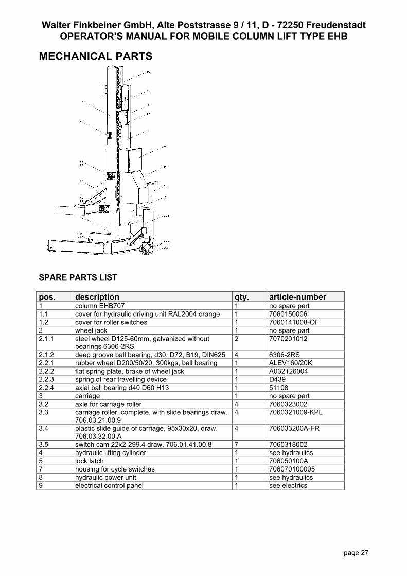
MECHANICAL PARTS
SPARE PARTS LIST pos. description qty. article-number 1 column EHB707 1 no spare part 1.1 cover for hydraulic driving unit RAL2004 orange 1 7060150006 1.2 cover for roller switches 1 7060141008-OF 2 wheel jack 1 no spare part 2.1.1 steel wheel D125-60mm, galvanized without
bearings 6306-2RS 2 7070201012
2.1.2 deep groove ball bearing, d30, D72, B19, DIN625 4 6306-2RS 2.2.1 rubber wheel D200/50/20, 300kgs, ball bearing 1 ALEV160/20K 2.2.2 flat spring plate, brake of wheel jack 1 A032126004 2.2.3 spring of rear travelling device 1 D439 2.2.4 axial ball bearing d40 D60 H13 1 51108 3 carriage 1 no spare part 3.2 axle for carriage roller 4 7060323002 3.3 carriage roller, complete, with slide bearings draw.
706.03.21.00.9 4 7060321009-KPL
3.4 plastic slide guide of carriage, 95x30x20, draw. 706.03.32.00.A
4 706033200A-FR
3.5 switch cam 22x2-299.4 draw. 706.01.41.00.8 7 7060318002 4 hydraulic lifting cylinder 1 see hydraulics 5 lock latch 1 706050100A 7 housing for cycle switches 1 706070100005 8 hydraulic power unit 1 see hydraulics 9 electrical control panel 1 see electrics

Walter Finkbeiner GmbH, Alte Poststrasse 9 / 11, D - 72250 Freudenstadt
OPERATOR’S MANUAL FOR MOBILE COLUMN LIFT TYPE EHB
page 28
CONFORMITY CERTIFICATE OF MANUFACTURER Lifting Equipment: EHB 707V11 Manufacturer: FINKBEINER-Lifting Systems Walter Finkbeiner GmbH Alte Poststrasse 9 / 11 D-72250 Freudenstadt Serial-No.: <<S/N>> Hereby we confirm that the above lifting equipment is designed and manufactured according to standing CE-Safety Regulations according to UVV-VBG14, EN1493 and CE for vehicle hoists. The lifting equipment has been approved with TÜV-Certificate No. 70/205/10.E00104/95. FINKBEINER-Lifting Systems Walter Finkbeiner GmbH Gerhard Finkbeiner
Walter Finkbeiner GmbH, Alte Poststrasse 9 / 11, D - 72250 Freudenstadt
OPERATOR’S MANUAL FOR MOBILE COLUMN LIFT TYPE EHB
page 29
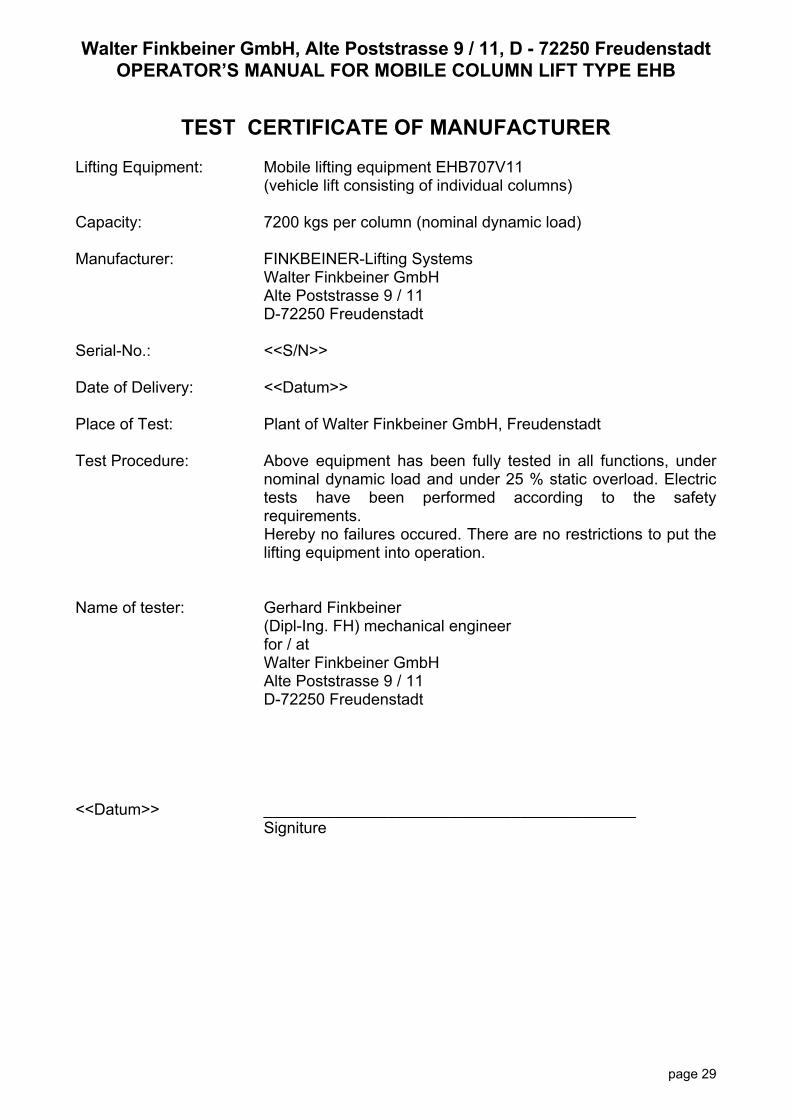
TEST CERTIFICATE OF MANUFACTURER
Lifting Equipment: Mobile lifting equipment EHB707V11 (vehicle lift consisting of individual columns) Capacity: 7200 kgs per column (nominal dynamic load) Manufacturer: FINKBEINER-Lifting Systems Walter Finkbeiner GmbH Alte Poststrasse 9 / 11 D-72250 Freudenstadt Serial-No.: <<S/N>> Date of Delivery: <<Datum>> Place of Test: Plant of Walter Finkbeiner GmbH, Freudenstadt Test Procedure: Above equipment has been fully tested in all functions, under
nominal dynamic load and under 25 % static overload. Electric tests have been performed according to the safety requirements. Hereby no failures occured. There are no restrictions to put the lifting equipment into operation.
Name of tester: Gerhard Finkbeiner (Dipl-Ing. FH) mechanical engineer for / at Walter Finkbeiner GmbH Alte Poststrasse 9 / 11 D-72250 Freudenstadt <<Datum>> __________________________________________
Signiture

Walter Finkbeiner GmbH, Alte Poststrasse 9 / 11, D - 72250 Freudenstadt
OPERATOR’S MANUAL FOR MOBILE COLUMN LIFT TYPE EHB
page 30

Walter Finkbeiner GmbH, Alte Poststrasse 9 / 11, D - 72250 Freudenstadt
OPERATOR’S MANUAL FOR MOBILE COLUMN LIFT TYPE EHB
page 31
Appendix - Inspection and testing GENERAL The following notes, together with an outline inspection and testing certificate, are included as a guide to assist management to meet ist obiligations. The operator, or other competent person, should record all the faults, difficulities and problems acturally experienced in the examination, checking, maintenance and operational use of the vehicle lift (e.g. corrosion, cracking, missing parts, hydraulic leaks). ITEMS RECOMMENDED FOR INSPECTION satisfactory unsatisfactory acceptable
criteria rated capacity displayed operating instructions displayed operator’s manual available make, model and serial no. displayed
vehicle access warning sign emergency stop switch up/down botton control lamps synchronizing switches switch cam on carriage interconnect cables with plugs sockets with lock clamps power supply cable with plug control panel closed and sealed structure of column and carriage (alignment and structural integrity)
structural cracking, welds corrosion travelling device carriage rollers lateral guide parts of carriage wheel forks secured by pin mechanical safety locking device hydraulic cylinder oil level hydraulic pressure oil leaks carriage rollers lubricated

Walter Finkbeiner GmbH, Alte Poststrasse 9 / 11, D - 72250 Freudenstadt
OPERATOR’S MANUAL FOR MOBILE COLUMN LIFT TYPE EHB
page 32
CERTIFICATE FOR ROUTINE, ANNUAL AND MAJOR TEST vehicle lift, serial-no. <<S/N>> sheet no.
The lifting equipment has been examined at a routine / annual / major*) test on .............……….. Herewith no / following*) failures have been founded. General condition description of equipment: _______________________________________________________________________________________ _______________________________________________________________________________________ _______________________________________________________________________________________ Description of test: _______________________________________________________________________________________ _______________________________________________________________________________________ Remarks: _______________________________________________________________________________________ _______________________________________________________________________________________
Outstanding tests: _______________________________________________________________ I certify that I have examined and tested as appropriate and find that the equipment is / is not *) in a satisfactory condition for safe use. Re-examination of equipment necessary / not necessary *) Competent person: ___________________________________________ (place, date) (signiture) name ___________________________________________ adress: __________________________ __________________________ qualification: __________________________ employed at: __________________________ company adress: __________________________ __________________________ knowledge of failures **) __________________________________________________________ failures repaired **) ______________________________________________________________

Walter Finkbeiner GmbH, Alte Poststrasse 9 / 11, D - 72250 Freudenstadt
OPERATOR’S MANUAL FOR MOBILE COLUMN LIFT TYPE EHB
page 33
*) strike out words not applicable **) confirmation of operator or management with date and signiture

Walter Finkbeiner GmbH, Alte Poststrasse 9 / 11, D - 72250 Freudenstadt
OPERATOR’S MANUAL FOR MOBILE COLUMN LIFT TYPE EHB
page 34
CERTIFICATE FOR ROUTINE, ANNUAL AND MAJOR TEST vehicle lift, serial-no. <<S/N>> sheet no.
The lifting equipment has been examined at a routine / annual / major*) test on .............……….. Herewith no / following*) failures have been founded. General condition description of equipment: _______________________________________________________________________________________ _______________________________________________________________________________________ _______________________________________________________________________________________ Description of test: _______________________________________________________________________________________ _______________________________________________________________________________________ Remarks: _______________________________________________________________________________________ _______________________________________________________________________________________
Outstanding tests: _______________________________________________________________ I certify that I have examined and tested as appropriate and find that the equipment is / is not *) in a satisfactory condition for safe use. Re-examination of equipment necessary / not necessary *) Competent person: ___________________________________________ (place, date) (signiture) name ___________________________________________ adress: __________________________ __________________________ qualification: __________________________ employed at: __________________________ company adress: __________________________ __________________________ knowledge of failures **) __________________________________________________________ failures repaired **) ______________________________________________________________

Walter Finkbeiner GmbH, Alte Poststrasse 9 / 11, D - 72250 Freudenstadt
OPERATOR’S MANUAL FOR MOBILE COLUMN LIFT TYPE EHB
page 35
*) strike out words not applicable **) confirmation of operator or management with date and signiture
CERTIFICATE FOR ROUTINE, ANNUAL AND MAJOR TEST vehicle lift, serial-no. <<S/N>> sheet no.
The lifting equipment has been examined at a routine / annual / major*) test on .............……….. Herewith no / following*) failures have been founded. General condition description of equipment: _______________________________________________________________________________________ _______________________________________________________________________________________ _______________________________________________________________________________________ Description of test: _______________________________________________________________________________________ _______________________________________________________________________________________ Remarks: _______________________________________________________________________________________ _______________________________________________________________________________________
Outstanding tests: _______________________________________________________________ I certify that I have examined and tested as appropriate and find that the equipment is / is not *) in a satisfactory condition for safe use. Re-examination of equipment necessary / not necessary *) Competent person: ___________________________________________ (place, date) (signiture) name ___________________________________________ adress: __________________________ __________________________ qualification: __________________________ employed at: __________________________ company adress: __________________________

Walter Finkbeiner GmbH, Alte Poststrasse 9 / 11, D - 72250 Freudenstadt
OPERATOR’S MANUAL FOR MOBILE COLUMN LIFT TYPE EHB
page 36
__________________________ knowledge of failures **) __________________________________________________________ failures repaired **) ______________________________________________________________ *) strike out words not applicable **) confirmation of operator or management with date and signiture
CERTIFICATE FOR ROUTINE, ANNUAL AND MAJOR TEST vehicle lift, serial-no. <<S/N>> sheet no.
The lifting equipment has been examined at a routine / annual / major*) test on .............……….. Herewith no / following*) failures have been founded. General condition description of equipment: _______________________________________________________________________________________ _______________________________________________________________________________________ _______________________________________________________________________________________ Description of test: _______________________________________________________________________________________ _______________________________________________________________________________________ Remarks: _______________________________________________________________________________________ _______________________________________________________________________________________
Outstanding tests: _______________________________________________________________ I certify that I have examined and tested as appropriate and find that the equipment is / is not *) in a satisfactory condition for safe use. Re-examination of equipment necessary / not necessary *) Competent person: ___________________________________________ (place, date) (signiture) name ___________________________________________ adress: __________________________ __________________________

Walter Finkbeiner GmbH, Alte Poststrasse 9 / 11, D - 72250 Freudenstadt
OPERATOR’S MANUAL FOR MOBILE COLUMN LIFT TYPE EHB
page 37
qualification: __________________________ employed at: __________________________ company adress: __________________________ __________________________ knowledge of failures **) __________________________________________________________ failures repaired **) ______________________________________________________________ *) strike out words not applicable **) confirmation of operator or management with date and signiture
CERTIFICATE FOR ROUTINE, ANNUAL AND MAJOR TEST vehicle lift, serial-no. <<S/N>> sheet no.
The lifting equipment has been examined at a routine / annual / major*) test on .............……….. Herewith no / following*) failures have been founded. General condition description of equipment: _______________________________________________________________________________________ _______________________________________________________________________________________ _______________________________________________________________________________________ Description of test: _______________________________________________________________________________________ _______________________________________________________________________________________ Remarks: _______________________________________________________________________________________ _______________________________________________________________________________________
Outstanding tests: _______________________________________________________________ I certify that I have examined and tested as appropriate and find that the equipment is / is not *) in a satisfactory condition for safe use. Re-examination of equipment necessary / not necessary *) Competent person: ___________________________________________ (place, date) (signiture) name

Walter Finkbeiner GmbH, Alte Poststrasse 9 / 11, D - 72250 Freudenstadt
OPERATOR’S MANUAL FOR MOBILE COLUMN LIFT TYPE EHB
page 38
___________________________________________ adress: __________________________ __________________________ qualification: __________________________ employed at: __________________________ company adress: __________________________ __________________________ knowledge of failures **) __________________________________________________________ failures repaired **) ______________________________________________________________ *) strike out words not applicable **) confirmation of operator or management with date and signiture