finite time thermodynamic analysis and optimization of ... · pdf filesharma, a., et al.:...
TRANSCRIPT

Sharma, A., et al.: Finite Time Thermodynamic Analysis and Optimization of … THERMAL SCIENCE, Year 2011, Vol. 15, No. 4, pp. 995-1009 995
FINITE TIME THERMODYNAMIC ANALYSIS AND OPTIMIZATION OF
SOLAR-DISH STIRLING HEAT ENGINE WITH
REGENERATIVE LOSSES
by
Arjun SHARMA a, Shailendra Kumar SHUKLA
a*, and Ajeet Kumar RAI
b
a Mechanical Engineering Department, Institute of Technology, Banaras Hindu University (B.H.U.), Varanasi, Uttar Prodesh, India
b Department of Mechanical Engineering and Applied Mechanics, Sam Higginbottom Instituute of Agriculture, Technology and Sciences, Allahabad, Uttar Pradesh, India
Original scientific paper UDC: 502.21:661.383.51
DOI: 10.2298/TSCI1104181015S
The present study investigates the performance of the solar-driven Stirling engine system to maximize the power output and thermal efficiency using the non-linea-rized heat loss model of the solar dish collector and the irreversible cycle model of the Stirling engine. Finite time thermodynamic analysis has been done for combined system to calculate the finite-rate heat transfer, internal heat losses in the regenerator, conductive thermal bridging losses, and finite regeneration process time. The results indicate that exergy efficiency of dish system increases as the effectiveness of regenerator increases but decreases with increase in rege-nerative time coefficient. It is also found that optimal range of collector tempera-ture and corresponding concentrating ratio are 1000 K~1400 K and 1100~1400, respectively, in order to get maximum value of exergy efficiency. It is reported that the exergy efficiency of this dish system can reach the maximum value when operating temperature and concentrating ratio are 1150 K and 1300, respective-ly.
Key words: solar parabolic dish collector, solar-driven Stirling engine, finite-rate heat transfer, exergy efficiency of dish system
Introduction
Electricity generation by solar power plants has gained importance in recent years.
Solar thermal power systems utilize the heat generated by a collector concentrating and
absorbing the Sun’s energy to drive a heat engine/generator and produce electric power.
Currently, three concepts are well known and established: Parabolic trough power plants,
solar tower power plants, and dish-Stirling systems. Out of these three the dish-Stirling
system has demonstrated the highest efficiency [1, 2]. Over the last 20 years, eight different
dish-Stirling systems ranging in size from 2 to 50 kW have been built by companies in the
United States, Germany, Japan, and Russia [1]. The Stirling energy system (SES) dish has
held the world’s efficiency record for converting solar energy into grid-quality electricity, and
*nCorresponding author; email: [email protected]

Sharma, A., et al.: Finite Time Thermodynamic Analysis and Optimization of … 996 THERMAL SCIENCE, Year 2011, Vol. 15, No. 4, pp. 995-1009
in January 2008, it achieved a new record of 31.25% efficiency rate. Dish-Stirling systems are
flexible in terms of size and scale of deployment. Owing to their modular design, they are
capable of both small-scale distributed power output, and suitable for large, utility-scale
projects with thousands of dishes arranged in a solar park (two plants in the US totaling over
1.4 GW are slated to begin construction in 2010 using the SES technology). In principle, high
concentrating and low or non-concentrating solar collectors can all be used to power the
Stirling engine. Finite time thermodynamics/finite temperature difference thermodynamics
deals with the fact that there must be a finite temperature difference between the working
fluid/substance and the source/sink heat reservoirs (with which it is in contact) in order to
transfer a finite amount of heat in finite time. The literature of finite time thermodynamics began with the novel work of Curzon et
al. [3], who established a theoretical model of a real Carnot heat engine at maximum power output with a different efficiency expression than the well known Carnot efficiency
*. In recent
years finite-time thermodynamics has been used successfully to study the performance analysis and optimization of low temperature differential Stirling heat engines [5, 6] powered by low concentrating solar collectors [7-9]. In addition, finite-time thermodynamics analysis of heat engines is usually restricted to systems having either linear heat transfer law dependence to the temperature differential both the reservoirs and engine working fluids [10, 11]. However, for higher temperature solar-powered heat engines, radiation and convection modes of heat transfer are often coupled and play a collective role in the processes of engines. Sahin [2] investigated the optimum operating conditions of endoreversible heat engines with radiation and convection heat transfer between the heat source and working fluid as well as convection heat transfer between the heat sink and the working fluid based on simultaneous processes. During the simultaneous processes, used as the steady-state operation in literature, the heat addition and heat rejection processes are assumed to take place simultaneously and are continuous in time as in a thermal power plant. The power output with simultaneous processes is given by in outW Q Q .
In this paper, a general analysis of finite time thermodynamics of a solar dish-
Stirling engine has been presented considering both convective and radiative heat transfer
phenomena between heat source/sink and working fluid. Optimization has been done by
varying the source temperature and concentration ratio. We have obtained the expression of
maximum power output and computed the corresponding thermal efficiency. The influence of
major parameters like heat leak coefficient, ratio of volume during regeneration processes,
regenerator losses etc on the maximum power output and the corresponding overall efficiency
is analyzed in detail. The aim of this article is to provide the basis for the design of a solar-
powered high temperature differential Stirling engine operated with a high concentrating
collector.
System description
As indicated in fig. 1, dish-engine systems use a mirror array to reflect and
concentrate incoming direct normal insolation to a receiver, in order to achieve the
temperatures required to efficiently convert heat to work. This requires that the dish track the
sun in two axes. The concentrated solar radiation is absorbed by the receiver (absorber) and
transferred to an engine.
* In 1977, Howel et al. analysed the Carnot cycle to determine the oprimum value of outlet temperature of solar collector with respect to maximum cycle work output [4].

Sharma, A., et al.: Finite Time Thermodynamic Analysis and Optimization of … THERMAL SCIENCE, Year 2011, Vol. 15, No. 4, pp. 995-1009 997
An endoreversible Stirling heat engine
coupled with a heat source and a heat sink,
and with a regenerator and conductive
thermal bridging losses from absorber to
heat sink is depicted in fig. 2 along with its
T-S diagram in fig. 3. The cycle approx-
imates the compression stroke of a real
Stirling heat engine as an isothermal heat
rejection process (1-2) to the low tempera-
ture sink. The heat addition to the working
fluid from the regenerator is modeled as the
constant volume process (2-3). The expan-
sion stroke producing work is modeled as
isothermal heat addition process (3-4) from
a high temperature heat source. Finally the
heat rejection to the regenerator is modeled
as the constant volume process (4-1). If the
regenerator is ideal, the heat absorbed during process 4-1 should be equal to the heat rejected
during process 2-3, however, the ideal regenerator requires an infinite area or infinite
regeneration time to transfer finite heat amount, and this is impractical. Therefore, it is
desirable to consider a real regenerator with heat losses ΔQR. In addition, we also consider
conductive thermal bridging losses Qb from the absorber to the heat sink.
Figure 2. Schematic diagram of the Stirling heat engine cycle
Figure 3. T-S diagram of solar dish-Stirling heat engine cycle
Finite time thermodynamics analysis
The analysis of the article includes the mathematical models for the dish solar
collector, the Stirling engine as well as the combination of the dish solar collector and the
Stirling engine.
Figure 1. Schematic diagram of the dish system

Sharma, A., et al.: Finite Time Thermodynamic Analysis and Optimization of … 998 THERMAL SCIENCE, Year 2011, Vol. 15, No. 4, pp. 995-1009
Thermal efficiency of the dish solar collector
Actual useful heat gain qu of the dish collector, considering conduction, convection,
and radiation losses is given by [12]:
4 4
u c 0 H H a H a[ ( ) ( )]q IA A h T T T T (1)
where I is the direct solar flux intensity, Ac – the collector aperture area, h0 – the collector
optical efficiency, AH – the absorber area, h – the conduction/convection coefficient, TH – the
absorber temperature, Ta – the ambient temperature, e – emissivity factor of the collector, and
s – the Stefan’s constant.
Thermal efficiency of the dish collector is defined by hd:
4 4
u H a H ad 0
c
( ) ( )Q h T T T T
IA IC (2)
Finite-time thermodynamics analysis of the Stirling heat engine
Regenerative heat loss to the regenerator
It should be pointed out that also the regenerative branches are affected by internal
thermal resistances to and from the thermal regenerator. Thus, regenerative losses are
inevitable. One may quantify these regenerative losses by [4]:
ΔQR = nCv (1 – εR) (T1 – T2) (3)
where, Cv is the heat capacity of the working substance, n – the number of mole partaking in
the regenerative branches, εR – the effectiveness of the regeneration and T1 and T2 are
temperatures of the working fluid in the high temperature isothermal process 3-4 and in the
low temperature isothermal process 1-2, respectively. When εR = 1 the Stirling cycle operators
with ideal (complete) regeneration.
To achieve a more realistic case, the time of the regenerative heat transfer processes
should also be considered in the thermodynamic analysis of a dish-Stirling heat engine [2].
For this purpose, it is assumed that the temperature of the engine working fluid/substance is
varying with time in the regenerative processes as given by [13]:
d
d
T
t (4)
where a is the proportionality constant which is independent of the temperature difference
and dependent only on the property of the regenerative material, called regenerative time
constant and the ± sign belong to the heating and cooling processes, respectively. The time (tr)
of two constant volume regenerative processes is given by:
tR = t3 + t4 =2a(T1 – T2) (5)
Heat transfer across the Stirling cycle
Heat supplied to the working fluid at temperature T1 (Q1) and the heat released by
the working fluid at temperature T2 (Q2), during the two isothermal processes are:

Sharma, A., et al.: Finite Time Thermodynamic Analysis and Optimization of … THERMAL SCIENCE, Year 2011, Vol. 15, No. 4, pp. 995-1009 999
1
1 h R 1 v R 1 2
2
R ln (1 )( )V
Q Q Q n T nC T TV
(6)
and
1
2 c R 2 v R 1 2
2
R ln (1 )( )V
Q Q Q n T nC T TV
(7)
respectively, where n is the mole number of the working substance, R – the universal gas
constant, T1 and T2 are the temperatures of the working substance during the high and low
temperature isothermal branches, and V1 and V2 – the volumes of the working substance along
the constant-volume heating and cooling branches, as shown in fig. 3.
Invariably, there are thermal resistances between the working substance and the
external heat reservoirs in the dish-Stirling engine. In order to obtain a certain power output,
the temperatures of the working substance must therefore be different from those of the heat
reservoirs. When convective and radiative heat transfer mode is consider between absorber
(source/sink) and working fluid, heat transfer can be written as:
Q1 = [hH(TH – T1) + hHR4 4
1 1( )]HT T t (8)
and
Q2 = hC(T2 – TC)t2 (9)
At sink side only convective mode is predominant. Here hH and hC are the thermal
conductances between the working substance and the heat reservoirs at temperatures TH and
TC, hHR is the high temperature side radiative heat transfer coefficient, and t1 and t2 are the
times spent on the two isothermal branches at temperatures T1 and T2, respectively.
The conductive thermal bridging losses from the absorber at temperature TH to the
heat sink at temperature TC is assumed to be proportional to the cycle time and given by [13,
14]:
Qa = ka(TH – TC)t (10)
where ka is the heat leak coefficient between the absorber and the heat sink and t – the cyclic
period.
Taking in account the major irreversibility mentioned above, the net heats released
from the absorber QH and absorbed by the heat sink QC are given as:
QH = Q1 + Qa (11)
QC = Q2 + Qa (12)
Thus the total cycle time is given by:
2 v R 1 21 2 3 4 4 4
H H 1 HR H 1
2 v R 1 2 1 2
C 2 L
R ln (1 )( )
( ) (
R ln (1 )( )
( ) 2
n T nC T Tt t t t t
h T T h T T
n T nC T T T T
h T T
(13)
For the thermodynamic cycle 1-2-3-4-1, work, power output, and thermal efficiency
is given by [15, 16]:

Sharma, A., et al.: Finite Time Thermodynamic Analysis and Optimization of … 1000 THERMAL SCIENCE, Year 2011, Vol. 15, No. 4, pp. 995-1009
W = QH – QC (14)
H CQ QW
Pt T
(15)
Using eqs. (8)-(15), we have:
1 2
1 1 1 2 2 1 1 22 1 24 4
C 2 CH H 1 HR H 1
( ) ( )( )
( )( ) ( )
T TP
T Y T T T Y T TY T T
h T Th T T h T T
(16)
1 2
1 1 1 24 4
H H 1 HR H 11 1 1 2 a H C
2 1 1 22 1 2
C 2 C
( )
( ) ( )( ) ( )
( )( )
( )
s
T T
T Y T T
h T T h T TT Y T T k T T
T Y T TY T T
h T T
(17)
where
v R
1
(1 )
R ln
CY and
2
2
R lnY
n
where λ = V1/V2.
For the sake of convenience, a new parameter x = T2/T1 is introduced into eqs. (16)
and (17), then we have:
1 1
1 1 1 1 1 1 1 12 1 14 4
C 1 CH H 1 HR H 1
( ) ( )( )
( )( ) ( )
T xTP
T Y T xT xT Y T xTY T xT
h xT Th T T h T T
(18)
To maximize the power output, take the derivative of eq. (18) with respect to the
temperature T1 and x and equate it to zero, namely ¶P/¶T1 = 0 and ¶P/¶x = 0, the optimal
working fluid temperature T1opt and xopt for this condition can be obtained from eq. (19) and
(20), respectively:
8 5 4 3 2
1 1opt 2 1opt 3 1opt 4 1opt 5 1opt 6 1opt 7 0T T T T T T (19)
2
1 2 3 0E x E x E (20)
where β1 = 2HR 1h B x , β2 = hHRx(2B1hHC – 3B2hLCx), β3 = 2hHRx(3B2hLCTL – B1B3 ), β4 =
= – 3B2hHRhLC2
LT , β5 = hHCx(B1hHC – B2hLCx), β6 = 2hHCx(B2hLCTL – B3B1), β7 = B1x23B –
– B2hHChLC2
LT , B1 = x + A1(1 – x), B2 = 1 + A1(1 – x), B3 = hHCTH + hHR4
HT , E1 = B( 21T –
– Y1T1TChC), E2 = B(Y1hC2
1T – Y1hCT1TC) + 21T hC, E3 = –[BhCT1(TL + Y1T1)] +
21T hC, B =
= hH(TH – T1) + hHR( 4HT – 4
1T )

Sharma, A., et al.: Finite Time Thermodynamic Analysis and Optimization of … THERMAL SCIENCE, Year 2011, Vol. 15, No. 4, pp. 995-1009 1001
Therefore, the maximum power output and the corresponding optimal thermal
efficiency of the Stirling engine are:
max.1 1
24 4C 1opt CH H 1opt HR H 1opt
1
1 (1 ) (1 )(1 )
( )( ) ( )
xP
Y x x Y xY x
h xT Th T T h T T
(21)
sopt1
4 4H H 1opt HR H 1opt
1 a H C
12
C 1opt C
1
1 (1 )
( ) ( )1 (1 ) ( )
(1 )(1 )
( )
x
Y x
h T T h T TY x k T T
x Y xY x
h xT T
(22)
Special cases:
(1) When hHR = 0, i. e. only convection heat transfer is considered and radiation heat transfer
is neglected between the absorber and the working fluid, eq. (19) is simplified to:
β5T1optT2 + β6T1opt + D7 = 0
By solving eq. (19) we get:
C 1 H
1opt
1
T FTT
x F
where
21
1 0.51
(1 )
[1 (1 )]
x Y x xF
Y x
(2) When εR = 1, the Stirling engine achieves the condition of perfect/ideal regeneration,
although the time of regeneration process is still considered. Then maximum power
output and thermal efficiency is given by:
max.
24 4C 1opt CH H 1opt HR H 1opt
1
1(1 )
( )( ) ( )
xP
xY x
h xT Th T T h T T
sopt
24 4C 1opt CH H 1opt HR H 1opt
1
11 ( ) (1 )
( )( ) ( )a H C
x
xk T T Y x
h xT Th T T h T T
(3) When hHR = 0, εR = 1, and considering x = (TH/TC)
1/2, then maximum power and thermal
efficiency can be given as:
22 H C
max. 22 2 H C
( )
1 ( )
F T TP
F Y T T

Sharma, A., et al.: Finite Time Thermodynamic Analysis and Optimization of … 1002 THERMAL SCIENCE, Year 2011, Vol. 15, No. 4, pp. 995-1009
Hsopt
C
1T
T
However, physically for finite time regenerative time εR should be less than unity. This
shows that in the investigation of the Stirling heat engine, it would be impossible to ob-
tain new conclusions if the regenerative losses were not considered.
(4) When the time of regenerative processes is directly proportional to the mean time of two
isothermal processes, i. e.
tr = γ(t1 + t2)
where γ is the proportionality constant then
max.
1 14 4
C 2 CH H 1opt HR H 1opt
1
1 (1 ) (1 )(1 )
( )( ) ( )
xP
Y x x Y x
h T Th T T h T T
sopt
1 11 a H C 4 4
C 2 CH H 1 HR H 1opt
1
1 (1 ) (1 )1 (1 ) ( )
( )( ) ( )
x
Y x x Y xY x k T T
h T Th T T h T T
(5) When the regenerative time is zero, i. e. tr = 0, the maximum power output is given by:
max.
1 14 4
C 2 CH H 1opt HR H 1opt
1
1 (1 ) (1 )
( )( ) ( )
xP
Y x x Y x
h T Th T T h T T
The maximum power and the corresponding
thermal efficiency of the system
The maximum power and the corresponding thermal efficiency of the system is
product of the thermal efficiency of the collector and the optimal thermal efficiency of the
Stirling engine [13]. Namely:
ηOv = ηdηsopt (23)
Using eqs. (2) and(22), we get:
4 4H a
Ov 0
14 4
H H 1opt HR H 1opt
1 a H C
12
1opt C
( ) ( )
1
1 (1 )
( ) ( )1 (1 ) ( )
(1 )(1 )
( )
H a
C
h T T T T
IC
x
Y x
h T T h T TY x k T T
x Y xY x
h xT T
(24)

Sharma, A., et al.: Finite Time Thermodynamic Analysis and Optimization of … THERMAL SCIENCE, Year 2011, Vol. 15, No. 4, pp. 995-1009 1003
Numerical results and discussions
In order to evaluate the effect of the absorber temperature (TH), the concentrating
ratio (C), the effectiveness of the regenerator (εR), the heat leak coefficient (k0), heat transfer
coefficients and volume ratio (λ) on the solar-powered dish-Stirling heat engine system, all
the other parameters will be kept constant as n = 10 mol, R = 4.3 J/molK, Cv = 15 J/molK, ε =
= 0.92, T0 = 300 K, h = 20 W/m2K, s = 5.67·10
–8 W/m
2K
4, a = 1000 K/s, and I = 1000 W/m
2.
The results obtained are as follows.
Effect on thermal efficiency of solar dish
The effect of the absorber temperature TH
and the concentrating ratio C on thermal effi-
ciency of the collector is shown in fig. 4.
From fig. 4, one can observe that the
thermal efficiency of the collector decreases
rapidly with increasing of the absorber
temperature TH, increases with the increasing
of concentration ratio C. This is predomi-
nantly due to increase in convective and
radiative heat losses at higher absorber
temperature. The maximum thermal efficiency
is limited by the optical efficiency of the
concentrator.
Effect on Stirling engine
Effect of absorber temperature (TH)
Figures 5-7 shows the variation on work output (W), maximum power output (Pmax)
and thermal efficiency of Sterling engine (ηs) with respect to absorber temperature (TH). Work
output and maximum power output both increase with increase in absorber temperature. Thus
it is desirable to have high temperature heat source to obtain higher power and work output.
Figure 5. Variation on work output of the Stirling engine with respect to absorber temperature
Figure 6. Variation on maximum power output of the Stirling engine with respect to absorber temperature
Figure 4. Variation of the thermal efficiency of the collector for different receiver temperature and the concentrating ratio

Sharma, A., et al.: Finite Time Thermodynamic Analysis and Optimization of … 1004 THERMAL SCIENCE, Year 2011, Vol. 15, No. 4, pp. 995-1009
Optical thermal efficiency of Stirling
engine increases rapidly at the beginning
and decrease slowly afterwards with the
increase of absorber temperature. The
optimum range of absorber temperature is
1150-1300 K where efficiency reaches at
its maximum value. The reason for the
decrease is conductive thermal bridging
losses from the absorber to the heat sink
whose effects are more pronounced at
higher absorber temperature.
Effect of heat sink temperature (TC)
It is seen from figs. 8-10 that as the heat
sink temperature increases, work output
decreases whereas maximum power output
and thermal efficiency of engine increases.
The decrease in work output is due to
increase in heat transfer at lower tempera-
ture of cycle. Power output increase due to
decrease in thermal bridging losses (Qa).
The effect of TC is more pronounced for
maximum power output and less pro-
nounced for heat input (Q1) to the heat
engine.
Effect of effectiveness of regenerator (εR)
As the regenerative effectiveness
increases, the heat transfers (Q1 and Q2)
decreases but the regenerative heat transfer
Figure 7. Variation on thermal efficiency of the Stirling engine with respect to absorber temperature
Figure 8. Variation on work output of the Stirling engine with respect to heat sink temperature
Figure 9. Variation on maximum power output of the Stirling engine with respect to heat sink temperature
Figure 10. Variation on thermal efficiency of the Stirling engine with respect to heat sink temperature

Sharma, A., et al.: Finite Time Thermodynamic Analysis and Optimization of … THERMAL SCIENCE, Year 2011, Vol. 15, No. 4, pp. 995-1009 1005
(QR) increases. It can be seen from figs.
11-13 that work output decreases with
effectiveness while maximum power
output increases. The decrease in work out-
put is due to decrease in optimum tempera-
ture at heat addition (T1opt) with increase in
effectiveness of regenerator. It is also
found that the optimal thermal efficiency
of the Stirling engine increases with the
increasing of the effectiveness of the rege-
nerator and is influenced greatly by it.
Effect on solar dish-Stirling system
Effect of TH and C
From fig. 14 it can be seen that for a given concentrating ratio, the maximum power
thermal efficiency of the system increases
with the increasing of the absorber tempera-
ture until the maximum thermal efficiency
is reached and then decreases with the
increasing of the absorber temperature; for
a given absorber temperature, the maximum
power thermal efficiency increases with the
increasing of the concentrating ratio. The
values of the optimum absorber temperature
and the concentrating ratio are about 1100
K and 1300, respectively, which makes the
thermal efficiency get up to its maximum
value about 33.16% which is close to
Carnot efficiency at about 50%, approx-
imately. It is also found that for a given
concentrating ratio, when the absorber tem-
Figure 11. Variation on work output of Stirling engine with respect to regenerator effectiveness
Figure 12. Variation on maximum power output of Stirling engine with respect to regenerator effectiveness
Figure 13. Variation on maximum power output of Stirling engine with respect to regenerator effectiveness
Figure 14. Variation on overall efficiency of system with respect to absorber temperature and concentration ratio
Sharma, A., et al.: Finite Time Thermodynamic Analysis and Optimization of … 1006 THERMAL SCIENCE, Year 2011, Vol. 15, No. 4, pp. 995-1009
perature exceeds its optimum value, if keep increasing the absorber temperature, the
maximum power thermal efficiency of the system decreases rapidly. This shows that the
range of the operation absorber temperature cannot exceed its optimum temperature, which is
very important for the solar dish collector because the absorber temperature varies with direct
solar flux intensity and changes with time.
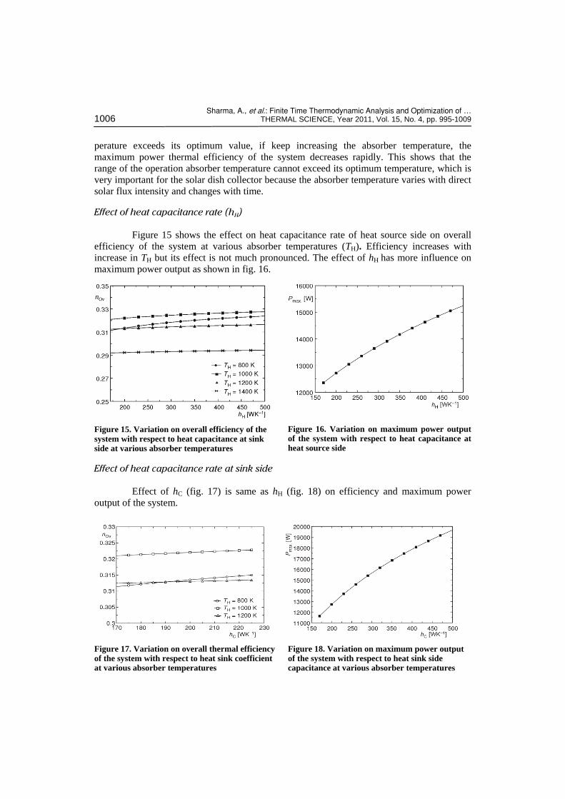
Effect of heat capacitance rate (hH)
Figure 15 shows the effect on heat capacitance rate of heat source side on overall
efficiency of the system at various absorber temperatures (TH). Efficiency increases with
increase in TH but its effect is not much pronounced. The effect of hH has more influence on
maximum power output as shown in fig. 16.
Figure 15. Variation on overall efficiency of the system with respect to heat capacitance at sink side at various absorber temperatures
Figure 16. Variation on maximum power output of the system with respect to heat capacitance at heat source side
Effect of heat capacitance rate at sink side
Effect of hC (fig. 17) is same as hH (fig. 18) on efficiency and maximum power
output of the system.
Figure 17. Variation on overall thermal efficiency of the system with respect to heat sink coefficient at various absorber temperatures
Figure 18. Variation on maximum power output of the system with respect to heat sink side capacitance at various absorber temperatures

Sharma, A., et al.: Finite Time Thermodynamic Analysis and Optimization of … THERMAL SCIENCE, Year 2011, Vol. 15, No. 4, pp. 995-1009 1007
Effect of cycle temperature ratio (x)
The variation of the power output
and thermal efficiency with respect to
the cycle temperature ratio (x = T1/T2)
for a typical set of operating parameters
is shown in fig. 19. It is seen from fig.19
that the power output first increase and
then decrease while the efficiency
monotonically decreases as the cycle
temperature ratio (x) decreases. These
properties can be directly expounded by
eqs. (21) and (24), because the power
output is not monotonic functions of x
while the efficiency is a monotonically
increasing function of x. The optimum
value of x ranges from 0.56-0.58.
Effect of heat leak coefficient (k0)
The effect of the heat leak coeffi-
cient on the maximum power thermal
efficiency of the system is shown in fig.
20. It is seen from the figure that the
heat leak coefficient reduces the effi-
ciency of system with increase and rate
of decrease is more at lower absorber
temperature.
Effect of effectiveness (εR)
The effect of the effectiveness of the
regenerator on the maximum power
thermal efficiency of the system is
shown in fig. 21. It is seen that the
maximum power efficiency increases
with the increasing of the effectiveness
of the regenerator. Therefore, the most
efficient and cost effective regenerator
should be used for the Stirling engine.
Conclusions
Finite-time thermodynamics has
been applied to optimize the maximum
power output and the corresponding
thermal efficiency of the solar-powered
Figure 19. Effect of temperature ratio on overall efficiency and power output of the system
Figure 20. Variation of the maximum power thermal efficiency of the dish system at different heat leak coefficient and the absorber temperature
Figure 21. Variation of the maximum power efficiency of the dish system for different effectiveness of the regenerator and the absorber temperature

Sharma, A., et al.: Finite Time Thermodynamic Analysis and Optimization of … 1008 THERMAL SCIENCE, Year 2011, Vol. 15, No. 4, pp. 995-1009
dish-Stirling heat engine with regenerative losses. It is found that regenerative effectiveness
and heat source/sink temperatures effects the optimum thermal efficiency and maximum
power output of the system. It is also desirable to have a high temperature heat source and low
temperature heat sink from the point of view of higher power output and the corresponding
thermal efficiency. Other factors like conductive thermal bridging losses, heat transfer
coefficients at source/sink side, temperature ratio of cycle and finite regenerative processes
time are also included in the analysis. The values of optimum absorber temperature (TH),
collector concentrating ratio (C) and temperature ratio (x) are about 1100 K, 1300, and 0.57,
respectively. Thus the present analysis provides a new theoretical basis for the design,
performance evaluation and improvement of solar dish-Stirling heat engine.
Nomenclature
A – heat transfer area, [m2] C – collector concentration ratio Cv – specific heat capacity, [Jmol–1K–1] h – heat transfer coefficient, [WK–1] or – [WK–4] or [Wm–2K–1] I – direct solar flux intensity, [Wm–2] ka – heat leak coefficient between the absorber – and the heat sing, [WK–1] n – the mole number of working fluid, [mol] P – power, [W] Q – heat transfer, [J] R – the gas constant, [Jmol–1K–1] T – temperature, [K] t – total cycle time, [s] W – work, [J]
Greeks symbols
ε – emissivity factor
εR – effectiveness of regenerator l – ratio of volume during regenerative – processes h – thermal efficiency s – Stefan’s constant, [Wm–2K–4]
Subscripts
a – ambient or optics C – heat sink c – collector H – absorber max. – maximum optimum condition R – regenerator 1, 2 – initial, final 1, 2, 3, 4 – state points
References
[1] Mancini, T., Heller, P., Dish-Stirling Systems: An Overview of Developmentand Status [J], J. Solar Energy Eng., 125 (2003), 2, pp. 135-151
[2] Sahin, A. Z., Finite-Time Thermodynamic Analysis of a Solar Driven Heat Engine, Exergy Int., 1, (2001), 2, pp. 122-126
[3] Curzon, F. L., Ahlborn, B., Efficiency of Carnot Heat Engine at Maximum Power Output, Am. J. Phys, 43 (1975), 2, pp. 22-24
[4] Howell, J. R., Bannerot, R. B., Optimum Solar Collector Operation for Maximizing Cycle Work Output, Solar Energy, 19 (1977), 2, pp. 149-153
[5] Wu, F, et al., Optimum Performance of Irreversible Stirling Engine with Imperfect Regeneration, Energy Conversion and Management, 39 (1998), 8, pp. 727-732
[6] Wu, F., et al., Performance and Optimization Criteria of Forward and Reverse Quantum Stirling Cycles, Energy Conversion and Management, 39 (1998), 8, pp. 733-739
[7] Chen, J., et. al., Efficiency Bound of a Solar-Driven Stirling Heat Engine System, Int. J. Energy Res., 22 (1998), 9, pp. 805-812
[8] Costea, M., Petrescu, S., Harman, C., The Effect of Irreversibilities on Solar Stirlingengine Cycle Performance, Energy Convers Manage, 40 (1999), 15-16, pp. 1723-1731
[9] Tlili, I., Timoumi, Y., Ben Nasrallah, S., Analysis and Design Consideration of Mean Temperature Differential Stirling Engine for Solar Application, Renew, Energy, 33 (2008) 3, pp. 1911-1921

Sharma, A., et al.: Finite Time Thermodynamic Analysis and Optimization of … THERMAL SCIENCE, Year 2011, Vol. 15, No. 4, pp. 995-1009 1009
[10] Chen, L., Li, J., Sun, F., Optimal Temperatures and Maximum Power Output of a Complex System with Linear Phenomenological Heat Transfer Law, Thermal Science, 13 (2009) 4, pp. 33-40
[11] Li, J., Chen, L., Sun, F., Maximum Work Output of Multistage Continuous Carnot Heat Engine System with Finite Reservoirs of Thermal Capacity and Radiation between Heat Source and Working Fluid, Thermal Science, 14 (2010), 1, pp. 1-9
[12] Thombare, D. G., Verma, S. K., Technological Development in the Stirling Cycle Engines, Renew Sustain Energy Rev., 12 (2008). 1, pp. 1-38
[13] Durmayaz, A., et al., Optimization of Thermal Systems Based on Finite-Time Thermodynamics and Thermoeconomics, Prog Energy Combust Sci., 30 (2004), 2, pp. 175-271
[14] Kaushik, S. C., Kumar, S., Finite Time Thermodynamic Evaluation of Irreversible Ericsson and Stirling Heat Engines, Energy Convers Manage, 42 (2001), 3, pp. 295-312
[15] Wu, F., et al., Performance Optimization of Stirling Engine and Cooler Based on Finite-Time Thermodynamic, Chemical Industry Press Beijing, 2008, pp. 59
[16] Yaqi, L., He, Y., Wang, W., Optimization of Solar-Powered Stirling Heat Engine with Finite-Time Thermodynamics, Renew, Energy, 36 (2010), 1, pp. 421-427
Paper submitted: April 18, 2011 Paper revised: September 15, 2011 Paper accepted: September 16, 2011