finite element specialists and engineering consultants · pdf fileanalysis is probably the...
TRANSCRIPT

Created 3rd
February 2015
Copyright © Ramsay Maunder Associates Limited (2004 – 2015). All Rights Reserved
Simulated Limit Analysis of Plates using Incremental Plasticity Finite Elements
Limit analysis is a form of plastic analysis that predicts the collapse load of a structural member
directly without recourse to the load history. The most commonly known and used form of limit
analysis is probably the yield line technique. Limit analysis assumes a perfectly plastic stress-strain
relationship and does not place any limits on the ductility of the member. Most practicing engineers
will not have access to software that can undertake limit analysis but they will generally have access
to commercial finite element software with a capability to conduct incremental plasticity. Limit
analysis may be simulated using an incremental FE analysis with a non-linear elastic, perfectly-plastic
material relationship and by increasing the load amplitude until the structural member can no longer
take any further load – i.e. it becomes a mechanism.
Verification is critical in any finite element analysis (remember the ‘Napoleonic Code’ – ‘guilty until
proven innocent’) and the first form of verification which needs to be conducted is that necessary to
ensure that the finite element software is actually capable of solving the sort of problem that the
engineer is considering. It is here that benchmark problems are important as they offer software
developers and analysts sets of problems for which the theoretically exact solution is either known
(usually in a closed-form solution) or for which appropriately verified numerical reference solutions
of reliable provenance are available.
The number of theoretically exact solutions for linear-elastic problems is fairly small and when
plasticity is included the number of such solutions dwindles still further. However there exist a
number of benchmark problems for plasticity that may be used to verify the finite element software
and begin to develop in the analyst the necessary faith that is required to extend their belief that the
software is capable of solving reliably their real world problems.
This document presents three plate plasticity benchmarks that might be used as verification
problems for the challenge problem. It should be noted here that we are dealing with thin plates for
which the Kirchhoff plate theory is appropriate. The first problem involves a square plate driven
with static boundary conditions that lead to a constant moment field both for the elastic case and
for the plastic case. As the load is increased the plate becomes plastic simultaneously everywhere
and the only redistribution of stress that occurs is through the cross section. It is a good problem to
consider since it can be modelled exactly with a single finite element. The second problem is one
presented in the NAFEMS documentation. It involves a simply supported square plate with a UDL.
The moment fields for this problem, both elastic and plastic, are non-linear and the problem has no
closed-form theoretical solution. The third problem is a variant on the first problem providing a
simpler support/loading system for modelling but also leading to a constant (torsional) moment
solution.
Finite Element Specialists and Engineering Consultants

Created 3rd
February 2015
Copyright © Ramsay Maunder Associates Limited (2004 – 2015). All Rights Reserved
Development of Plasticity in a Section under Bending
The ability of structural elements to resist bending actions requires materials that work equally well
in both tension and compression. Stone or plain concrete, for example, are materials that cannot be
safely assumed to possess any significant strength in tension and so cannot sensibly resist bending
actions.
Many metals, on the other hand, are as strong in tension as they are in compression and therefore
are ideally suited to resisting bending actions. The design of members to resist bending actions
involves, in the first instance, an understanding of how externally applied loads convert into internal
bending moments and once these are established then, for a given material, section properties are
established such that the bending moments may be safely resisted. How one establishes the
internal bending moments depends on the complexity of the structure. For statically determinate
beams the bending moments come from a consideration of statics alone. For statically
indeterminate beam and plate members generally the only practical way of establishing these
quantities is through finite element analysis.
In traditional elastic design the section is sized so that under the worst working load configuration
the maximum bending stress does not exceed some factor (less than unity) of the yield stress for the
material. Ultimate Limit State design further requires the structure not to collapse under the most
severe loads it is likely to encounter. So the designer is generally interested in the load to cause first
yield and the load to cause collapse. For structural members under uniaxial tension these loads
coincide. However for members under bending, where plasticity has to develop through the section
before collapse occurs, the load to collapse the member can be significantly greater than that to
cause first yield. This point can be conveniently demonstrated by considering how the stress
develops in a member under bending as the bending moment is increased.
Figure 1: Moment/Rotation relationship for a section under bending
The yellow line in this
figure indicates how
the stress at the
surface increases
linearly until it reaches
yield. The green line
indicates the degree of
penetration of yield
through the section.

Created 3rd
February 2015
Copyright © Ramsay Maunder Associates Limited (2004 – 2015). All Rights Reserved
Referring to figure 1 it is seen that for low load amplitudes the bending moment leads to a linear
normal stress distribution through the section as shown in the elastic portion of the figure. As the
load increases an amplitude will be reached when the outer surfaces of the beam just reach the yield
stress of the material. The moment at this point is the moment to cause first yield �� . As the stress
cannot increase beyond the yield stress, further increasing the load changes the linear stress
distribution to that shown in the figure where � defines the depth to which plasticity has penetrated
the section. The load can be increased until � = �� at which point the section has become fully
plastic and the collapse moment �� is reached. Whereas the elastic portion of the curve was
assumed to be linear so that the stiffness was constant, as the moment increases through the
partially plastic region the stiffness decreases until collapse is reached and the stiffness is reduced to
zero. The collapse moment is 50% greater than the moment to cause first yield, i.e., �� = ����.
As engineers we should be very familiar with the result that for a section under bending the load to
cause section failure is 50% greater than the load to cause first yield. This value of strength
enhancement whilst correct for a statically determinate beam, may not be so for statically
indeterminate beam and plate members where moment redistribution may occur along the length
of the beam, or across the plane of the plate, in addition to through the section. For these cases the
strength enhancement can be considerably greater than the 50% noted for the statically
determinate beam.
The manner in which the bending moments redistribute is governed by the chosen yield criterion.
The von Mises yield criterion, which is appropriate to steel members and thus for the challenge
problem, is shown in figure 2 where it is presented in terms of normalised principal moments which
are simply the principal moments divided by the collapse moment, e.g. for the first principal
moment we have � = ��� .
Figure 2: The von Mises yield criterion in terms of normalised principal moments
The figure shows two von Mises
ellipses the smaller one being that of
first yield and the large one being that
of collapse moment. The inset figures
in the corners shows the principal
moments acting on an infinitesimal
element of the plate (green and blue
for the first and second principal
moments respectively). It also shows
the direction of the direct stresses at
the top surface of the plate developed
by these applied moments.
The green arrow indicates the moment
state as the section is loaded to
collapse.
The red and blue arrows pertain to the
two load cases presented in
Benchmark Number 1.

Created 3rd
February 2015
Copyright © Ramsay Maunder Associates Limited (2004 – 2015). All Rights Reserved
Benchmark Number 1 - Square Plate with Applied Constant Moment Field
The constant moment plate problem is shown in figure 3. A square plate, with unit side length, is
shown together with the boundary tractions (uniform normal moment distributions in this case)
corresponding to the given exact solution.
Figure 3: The constant moment plate problem
Plastic collapse is governed by the yield criterion and we will consider the von Mises yield criterion
which may be written in terms of the principal moments:
�� +��� −��� ≤ ���
The load factor, �, is a non-dimensional constant that scales the applied loads and we are interested
in determining the value at which the plate will collapse. As the moment field for this problem
involves no torsional moments then the principal moments are simply equal to the normal Cartesian
components � = �� and �� = ��. We can thus determine the load factor at collapse,��, in terms
of the collapse moment and the amplitudes of the unfactored normal moments:
�� = ��√�� + �� − ��
Two sample load cases will be considered by taking two particular sets of unit values for the normal
moments the corresponding collapse load factors can be calculated.
� = � = 1 → �� = �� = 6875 (hogging; hogging) - Load Case 1
� = −� = 1 → �� = � √� ≈ 3969.28 (hogging; sagging) - Load Case 2
As noted already, for this problem there can be no moment redistribution in the plane of the plate
and all points in the plane reach collapse simultaneously. The load history of all points in the plane
of the plate for the two load cases is shown in figure 2.
This is an extremely simple problem to analyse in any finite element system and has the added
bonus that a single square element (four-noded or eight-noded) should be able to recover the exact
solution. The consistent nodal moments for load case 1 are shown in figure 4 for both four-noded
x
y
! �"�#�"#$ = � %��0'
�� = (#)�4 = 6875Nm/m
Geometric Properties – . = 1�; ) = 0.01�
Elastic Properties – 0 = 21012�; 3 = 0.3
Plastic Properties – (# = 27542�
�5�/�
�5�/�

Created 3rd
February 2015
Copyright © Ramsay Maunder Associates Limited (2004 – 2015). All Rights Reserved
and eight-noded elements. The problem is in static equilibrium under the applied loads and so the
only supports necessary are those to restrain the three plate-bending rigid-body modes and, if a
shell element is being used, the three plate membrane rigid-body modes. One possible suitable set
of nodal supports is indicated in the figure. The consistent nodal moments for load case 2 are
identical to those of load case 1 except that the direction of the moments on the top and bottom
edges should be reversed.
Four-Noded Eight-Noded
Figure 4: Consistent nodal moments for single four-noded and eight-noded elements (load case 1)
In considering the finite element analysis of plates, it should be noted that most commercial finite
element systems provide the user with results in terms of stresses at various locations through the
section – typically top, bottom and middle sections. Thus, if the plane of the plate is Z=constant
then the direct stresses (", (#and the shear stress 7"#will be provided. The equations relating
moment to stress given in figure 1 may be used to convert these stresses into the direct moments �" ,�# and the torsional moment �"#.
Benchmark Number 2 - NAFEMS Plastic Plate Problem NL7A
NAFEMS provide a benchmark problem very similar to the challenge problem except that it is for a
simply supported square plate under UDL rather than the challenge rectangular plate. This
benchmark problem is shown for convenience in figure 5. With regard to this figure it should be
noted that with a span/depth ratio of 100 the plate should be considered as ‘thin’. Nonetheless, the
results presented are for a ‘thick’ plate formulation. However as the target finite element solution
appears to converge to the correct ‘thin’ plate solution the thick plate element formulation seems
capable of capturing the correct solution.
The reference solution provided for NL7A is 0.01800 and is derived by yield line analysis. RMA have
used their lower-bound limit analysis software (EFE) to generate a solution for NL7A and this gives
0.01876. As this is a lower-bound method the theoretically exact solution is greater than this so that
one can see immediately (since it cannot be an upper-bound) that the value obtained by yield line
(which is an upper-bound method), whilst close, is not correct. The solution generated by EFE is in
very close agreement with the target solution shown for NL7A and should be used instead of the
yield line value.
#
#
1
2
3
589:1:<" = <# = <= = 0
589:2:<" = <= = 0
589:3:<= = 0
125� 165�
235�

Created 3rd
February 2015
Copyright © Ramsay Maunder Associates Limited (2004 – 2015). All Rights Reserved
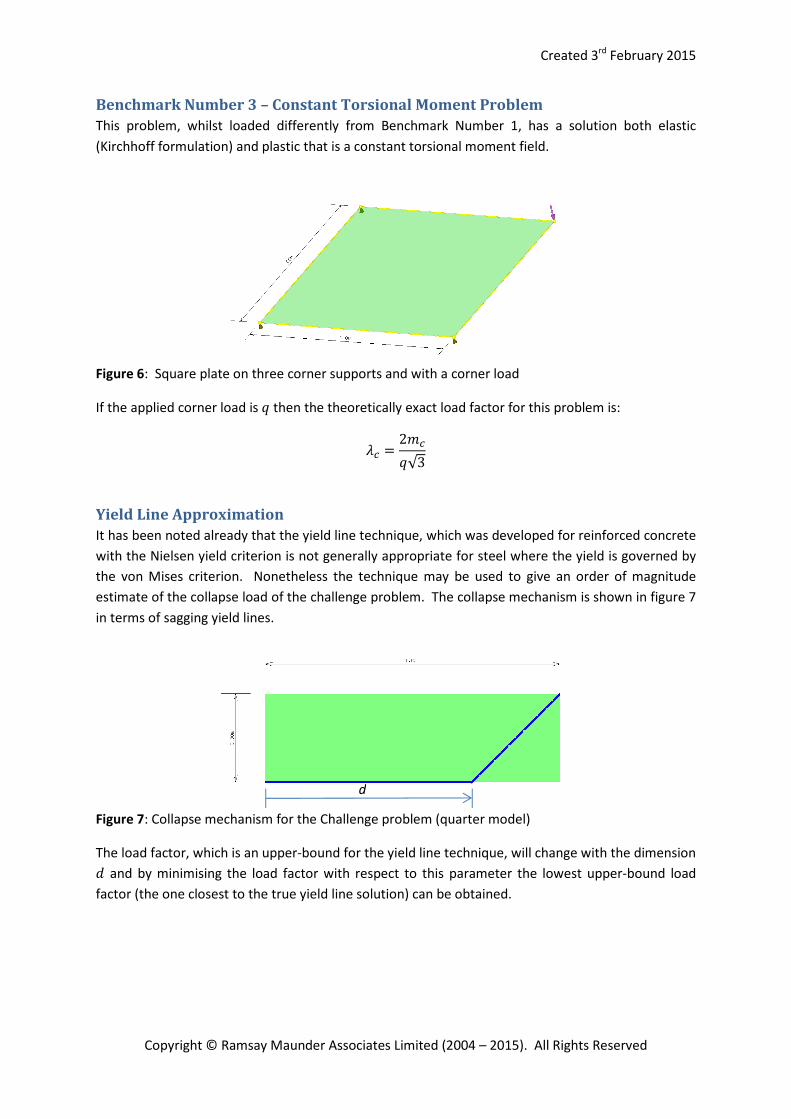
Benchmark Number 3 – Constant Torsional Moment Problem
This problem, whilst loaded differently from Benchmark Number 1, has a solution both elastic
(Kirchhoff formulation) and plastic that is a constant torsional moment field.
Figure 6: Square plate on three corner supports and with a corner load
If the applied corner load is > then the theoretically exact load factor for this problem is:
�� = 2��>√3
Yield Line Approximation
It has been noted already that the yield line technique, which was developed for reinforced concrete
with the Nielsen yield criterion is not generally appropriate for steel where the yield is governed by
the von Mises criterion. Nonetheless the technique may be used to give an order of magnitude
estimate of the collapse load of the challenge problem. The collapse mechanism is shown in figure 7
in terms of sagging yield lines.
Figure 7: Collapse mechanism for the Challenge problem (quarter model)
The load factor, which is an upper-bound for the yield line technique, will change with the dimension 9 and by minimising the load factor with respect to this parameter the lowest upper-bound load
factor (the one closest to the true yield line solution) can be obtained.
d