finite element simulation of cutting processes€¦ · lecture 8 laboratory for machine tools and...
TRANSCRIPT

© WZL/Fraunhofer IPT
Finite element simulation of cutting
processes
Simulation Techniques in Manufacturing Technology
Lecture 8
Laboratory for Machine Tools and Production Engineering
Chair of Manufacturing Technology
Prof. Dr.-Ing. Dr.-Ing. E.h. Dr. h.c. Dr. h.c. F. Klocke

Seite 2 © WZL/Fraunhofer IPT
Summary and Outlook 9
Applications of the FE cutting simulation at the WZL 8
Criteria for the evaluation of FE software 7
Friction and wear models for the FE cutting simulation 6
Damage models for the FE cutting simulation and multiphase simulation 5
Constitutive material laws for the FE cutting simulation 4
CAD modelling for the FE cutting simulation 3
Requirements of the FE cutting simulation 2
Introduction 1
Outline

Seite 3 © WZL/Fraunhofer IPT
Influencing factors on the cutting process
Workpiece material
structure
texture
mechanical
properties
hardness
residual stresses
Cutting zone
chip forming
mechanisms
cooling lubricant
cutting parameters
contact
conditions
e.g.: friction, wear
heat transfer
Tool
cutting material
coating
geometry
tool holder
Machine
machine design
drive system
clamping device
Bild
eines
Prozesses
M

Seite 4 © WZL/Fraunhofer IPT
Cutting process in comparison to other processes
Source: Jaspers
Process Strain Strain rate / s-1 Thomolog
Extrusion 2 – 5 10-1 – 10-2 0.16 – 0.7
Forging /
Rolling 0.1 – 0.5 10 – 10+3 0.16 – 0.7
Sheet metal
forming 0.1 – 0.5 10 – 10+2 0.16 – 0.7
Cutting 1 – 5 10+3 – 10+6 0.16 – 0.9
Cutting process
Extreme conditions in the cutting process

Seite 5 © WZL/Fraunhofer IPT
Outline
Summary and Outlook 9
Applications of the FE cutting simulation at the WZL 8
Criteria for the evaluation of FE software 7
Friction and wear models for the FE cutting simulation 6
Damage models for the FE cutting simulation and multiphase simulation 5
Constitutive material laws for the FE cutting simulation 4
CAD modelling for the FE cutting simulation 3
Requirements of the FE cutting simulation 2
Introduction 1

Seite 6 © WZL/Fraunhofer IPT
Requirements to the FE cutting simulation
Reproduction of the macro/ micro geometry of the tools and kinematic of the cutting
process
Modelling of the thermo mechanical material behavior for the entire temperature and
strain rate range
Implementation of damage approaches, texture microstructure and phase transformation
Simulation of chip form (remeshing routine, material separation, etc.)
Consideration of friction, wear and coating
Modelling of heat generation and transfer (conduction, convection, radiation)
Consideration of the influence of cooling lubricant
Utilization of the Lagrangian solving method (instationary cutting processes)
Generation of a finely structured FE mesh and adaptive remeshing (very high element
deformation because of higher gradients of deformation, temperature and tension)
Appropriate computation time (explicit time integration, parallelization, etc.)
Seite 7 © WZL/Fraunhofer IPT
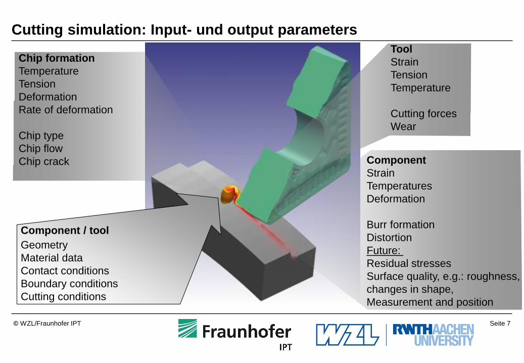
Cutting simulation: Input- und output parameters
Tool
Strain
Tension
Temperature
Cutting forces
Wear
Chip formation
Temperature
Tension
Deformation
Rate of deformation
Chip type
Chip flow
Chip crack Component
Strain
Temperatures
Deformation
Burr formation
Distortion
Future:
Residual stresses
Surface quality, e.g.: roughness,
changes in shape,
Measurement and position
Component / tool
Geometry
Material data
Contact conditions
Boundary conditions
Cutting conditions
Seite 8 © WZL/Fraunhofer IPT
Outline
Summary and Outlook 9
Applications of the FE cutting simulation at the WZL 8
Criteria for the evaluation of FE software 7
Friction and wear models for the FE cutting simulation 6
Damage models for the FE cutting simulation and multiphase simulation 5
Constitutive material laws for the FE cutting simulation 4
CAD modelling for the FE cutting simulation 3
Requirements of the FE cutting simulation 2
Introduction 1

Seite 9 © WZL/Fraunhofer IPT
Macro- und micro tool geometry
Major clearance angle: a = 10°
Twist angle: d = 35°
Cutting material: HW-K20
Grain size: DK = 0.5 – 0.7 µm
Construction dimensions DIN 6539
Type: N
Diameter: d = 1 mm
Drill-point angle: s = 118°
Querschneide
Freifl ä che
Hauptschneide a
d
chisel edge
flank face
major cutting edge a
d
Seite 10 © WZL/Fraunhofer IPT
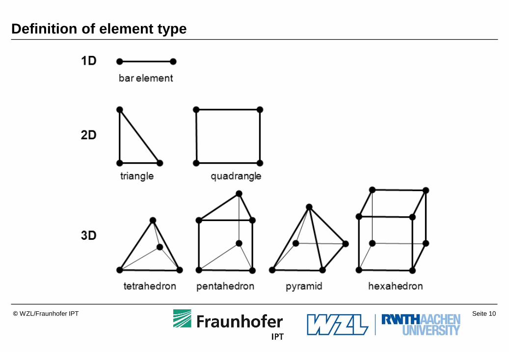
Definition of element type

Seite 11 © WZL/Fraunhofer IPT
Creation of tool models close to reality
Macro
geometry
4 mm
Drilling tool FEM-model Determination of the tool geometry
Micro
geometry
6 µm 6 µm
Real tool CAD-model
Seite 12 © WZL/Fraunhofer IPT
Zusammenfassung und Ausblick 9
Outline
Zusammenfassung und Ausblick Zusammenfassung und Ausblick Zusammenfassung und Ausblick Summary and Outlook 9
Applications of the FE cutting simulation at the WZL 8
Criteria for the evaluation of FE software 7
Friction and wear models for the FE cutting simulation 6
Damage models for the FE cutting simulation and multiphase simulation 5
Constitutive material laws for the FE cutting simulation 4
CAD modelling for the FE cutting simulation 3
Requirements of the FE cutting simulation 2
Introduction 1

Seite 13 © WZL/Fraunhofer IPT
Thermo-mechanical behavior of material
i iB u

Seite 14 © WZL/Fraunhofer IPT
Thermo-mechanical behavior of material
Quelle: Diss-Abouridoaune
( , , )Ts s
200
250
300
350
400
450
0 0.1 0.2 0.3 0.4
AA6063-T6
d/dt=10-3
s-1
& T=20°C
, -
s ,
M
Pa
300
350
400
450
10-3
10-1
101
103
AA6063-T6
=0.1 & T=20°C
d/dt , s-1
0
150
300
450
0 100 200 300 400 500
AA6063-T6
=0.1 & d/dt=1s-1
T , °C
Strain Rate HardeningStrain Hardening Thermal Softening
Source: Diss- Abouridouane
Seite 15 © WZL/Fraunhofer IPT
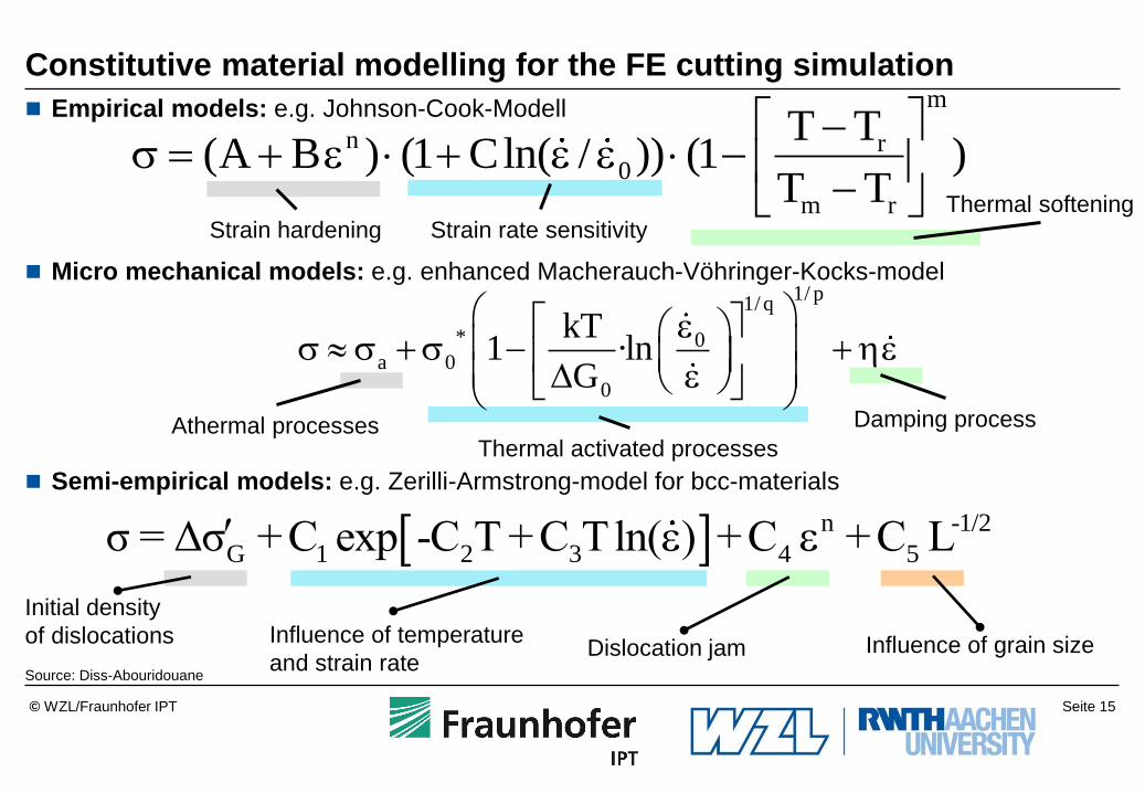
Empirical models: e.g. Johnson-Cook-Modell
Micro mechanical models: e.g. enhanced Macherauch-Vöhringer-Kocks-model
Semi-empirical models: e.g. Zerilli-Armstrong-model for bcc-materials
Constitutive material modelling for the FE cutting simulation
Source: Diss-Abouridouane
n -1/2
G 1 2 3 4 5σ = Δσ +C exp -C T +C Tln( ) +C +C L
Initial density
of dislocations Dislocation jam
Influence of temperature
and strain rate Influence of grain size
m
n r0
m r
T T(A B ) (1 Cln( / )) (1 )
T T
s
Strain hardening Strain rate sensitivity
Thermal softening
1/ p1/ q
* 0a 0
0
kT1 ·ln
G
s s s
Athermal processes Damping process
Thermal activated processes

Seite 16 © WZL/Fraunhofer IPT
Determination of High speed flow curves
Source: LFW
Split-Hopkinson-Pressure-Bar
AusgangsstabEingangsstab
Lager
Lager
Joch Projektil
Rohr
Zugprobe
Deckel mit
Luftanschluss
Pressluftbehälter mitSchnellöffnungsventil
AusgangsstabEingangsstab
Lager
Lager
Joch Projektil
Rohr
Zugprobe
Deckel mit
Luftanschluss
Pressluftbehälter mitSchnellöffnungsventil
Split-Hopkinson-Tension-Bar
Strain rate: 500 s-1 – 10000 s-1
Temperature range: 93 K – 1273 K
Projectile speed: 2,5 m/s – 50 m/s
Projectile mass: m = 3,15 kg
Geweda
Prof. El-Magd Joke Projectile Input rod
Tensile specimen Output rod
Tube Cover with air
connection
Air cylinder with
quick release valve
Lager LagerProbe
Temperier-
kammerAusgangsstabEingangsstab
Rohr
Preßluftbehälter
Projektil
AuffangbehälterCollection bag Sample
Input rod Output rod
Tube
Projectile
Air cylinder
Temperature
chamber
Bearing
Bearing Bearing
Bearing

Seite 17 © WZL/Fraunhofer IPT
Material law for high strain rate deformation
Source: Diss-Brodmann
dtBKa
BKk
n
n
adf
)(1
4 0 0
5 0 0
6 0 0
7 0 0
8 0 0
0 0 . 2 0 . 4 0 . 6 0 . 8
d / d t = 5 0 1 0 s
- 1
4 8 8 9 s - 1
4 3 5 0 s - 1
4 2 9 4 s - 1
3 4 5 0 s - 1
3 4 3 9 s - 1
2 5 5 8 s - 1
2 5 2 9 s - 1
0 . 0 0 1 s - 1
o : r
K = 9 6 0 M P a B = 0 . 0 3 1 n = 0 . 1 8 2
/ K = 6 . 2 5 · 1 0 - 6
s
A A 7 0 7 5 T 7 3 5 1 D r u c k v e r s u c h e
w
a h r e
S p a n n u n g , M
P a
True plastic strain, -
Lines: Calculation
Symbols: experiments
Pressure tests
Tru
e S
tress,
M
PA

Seite 18 © WZL/Fraunhofer IPT
Outline
Summary and Outlook 9
Applications of the FE cutting simulation at the WZL 8
Criteria for the evaluation of FE software 7
Friction and wear models for the FE cutting simulation 6
Damage models for the FE cutting simulation and multiphase simulation 5
Constitutive material laws for the FE cutting simulation 4
CAD modelling for the FE cutting simulation 3
Requirements of the FE cutting simulation 2
Introduction 1

Seite 19 © WZL/Fraunhofer IPT
Failure mechanisms
Source: Diss-Abouridouane
Loading type
Shear stress Tensile stress
TiAl6V4
20 µm 20 µm
Shear lokalisation model
(Imperfections theory)
Pore growth model
(Hancock-Mackenzie)
Seite 20 © WZL/Fraunhofer IPT
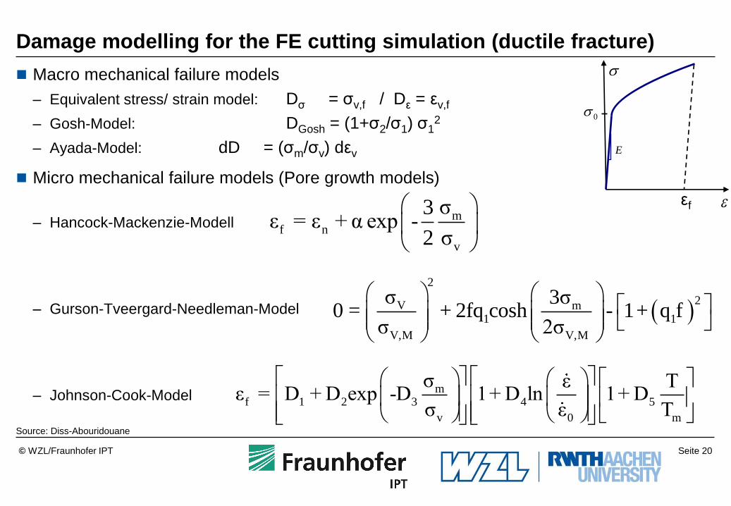
Damage modelling for the FE cutting simulation (ductile fracture)
Macro mechanical failure models
– Equivalent stress/ strain model: Dσ = σv,f / Dε = εv,f
– Gosh-Model: DGosh = (1+σ2/σ1) σ12
– Ayada-Model: dD = (σm/σv) dεv
Micro mechanical failure models (Pore growth models)
– Hancock-Mackenzie-Modell
– Gurson-Tveergard-Needleman-Model
– Johnson-Cook-Model
Source: Diss-Abouridouane
m
f 1 2 3 4 5
v 0 m
σ ε Tε = D + D exp -D 1+ D ln 1+ D
σ ε T
m
f n
v
σ3ε = ε + α exp -
2 σ
2
2V m1 1
V,M V,M
σ 3σ0 = + 2fq cosh - 1+ q f
σ 2σ
s
0s
E
εf

Seite 21 © WZL/Fraunhofer IPT
Failure limit at tensile stress (r: Notch radius)
Source: Diss-Abouridouane
0
0.5
1.0
1.5
0 0.5 1.0 1.5 2.0 2.5
glattr = 1.2 mmr = 0.8 mmr = 0.4 mmr = 0.02 mm
TiAl6V4, = 200°Cdynamisch
f = 0.09+3.54*exp(-2.61*s
m/s
v)
0
0.5
1.0
1.5
0 0.5 1.0 1.5 2.0 2.5
glattr = 1.2 mmr = 0.8 mmr = 0.4 mmr = 0.02 mm
TiAl6V4, = 200°Cquasistatisch
f = 0.09+5.2*exp(-2.35*s
m/s
v)
Mehrachsigkeit sm
/sv
lokal
e pla
stis
che
Bru
ch-V
ergle
ichsd
ehnung
f
0
0.2
0.4
0.6
0.8
1.0
0 0.5 1.0 1.5 2.0 2.5
glattr = 1.2 mmr = 0.8 mmr = 0.4 mmr = 0.02 mm
TiAl6V4, = 20°Cquasistatisch
f = 0.05+2.89*exp(-2.35*s
m/s
v)
0
0.2
0.4
0.6
0.8
1.0
0 0.5 1.0 1.5 2.0 2.5
glattr = 1.2 mmr = 0.8 mmr = 0.4 mmr = 0.02 mm
TiAl6V4, = 20°Cdynamisch
f = 0.05+2.33*exp(-2.49*s
m/s
v)
Local pla
stic f
ailu
re-e
quiv
ale
nt
str
ess ε
f
Multiaxiality
dynamic
dynamic quasi-static
quasi-static
Seite 22 © WZL/Fraunhofer IPT
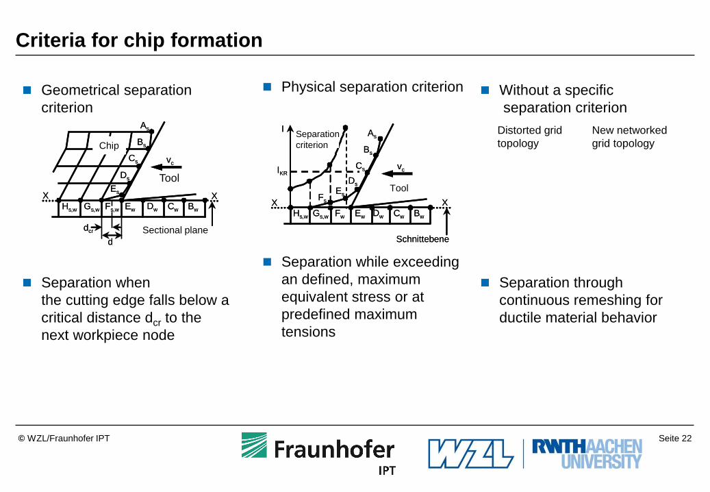
Criteria for chip formation
Geometrical separation
criterion
Separation when
the cutting edge falls below a
critical distance dcr to the
next workpiece node
Without a specific
separation criterion
Separation through
continuous remeshing for
ductile material behavior
Physical separation criterion
Separation while exceeding
an defined, maximum
equivalent stress or at
predefined maximum
tensions
Werkzeug
As
Bs
Cs
Ds
Es
Hs,w Gs,w Fs,w Ew Dw Cw Bw
X X
dcr
dSchnittebene
vc
Span
Werkzeug
vc
As
Bs
Cs
Ds
Es
Hs,w Gs,w Fw Ew Dw Cw Bw
X X
Schnittebene
Fs
I
IKR
Trenn-
kriterium
Werkzeug
As
Bs
Cs
Ds
Es
Hs,w Gs,w Fs,w Ew Dw Cw Bw
X X
dcr
dSchnittebene
vc
Span
Werkzeug
vc
As
Bs
Cs
Ds
Es
Hs,w Gs,w Fw Ew Dw Cw Bw
X X
Schnittebene
Fs
I
IKR
Trenn-
kriterium
Geometrischen Trennkriterium Physikalisches Trennkriterium
Werkzeug
As
Bs
Cs
Ds
Es
Hs,w Gs,w Fs,w Ew Dw Cw Bw
X X
dcr
dSchnittebene
vc
Span
Werkzeug
vc
As
Bs
Cs
Ds
Es
Hs,w Gs,w Fw Ew Dw Cw Bw
X X
Schnittebene
Fs
I
IKR
Trenn-
kriterium
Werkzeug
As
Bs
Cs
Ds
Es
Hs,w Gs,w Fs,w Ew Dw Cw Bw
X X
dcr
dSchnittebene
vc
Span
Werkzeug
vc
As
Bs
Cs
Ds
Es
Hs,w Gs,w Fw Ew Dw Cw Bw
X X
Schnittebene
Fs
I
IKR
Trenn-
kriterium
Geometrischen Trennkriterium Physikalisches Trennkriterium
Distorted grid
topology
New networked
grid topology
Tool Tool
Tool
Separation
criterion
Tool
Chip
Sectional plane
Seite 23 © WZL/Fraunhofer IPT
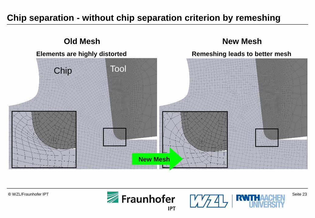
Chip separation - without chip separation criterion by remeshing
Old Mesh
Elements are highly distorted
New Mesh
Remeshing leads to better mesh
Span Werkzeug a) b) Chip Tool
New Mesh

Seite 24 © WZL/Fraunhofer IPT
0
300
600
900
1200
0 0.5 1.0 1.5 2.0
True plastic strain , , -T
rue
str
ess
M
Pa
CompressionTension
Ø 0.1x0.1 mm
Shear
0.1x0.1x0.1 mmQuasi-static
FE model
Experiment
Tension stress
Compression stress
Shear stress
Microstructure-based 3D modeling for micro cutting AISI 1045
Concept of the Representative Volume Element (RVE)
Macrostructure
Microstructure
RVE
Representativeness check of the RVE Capture of all significant microstructural
inhomogeneities
Pearlite
Cross section Longitudinal section
Two-phase 3D FE model(0.1 x 0.1 x 0.1 mm)
Ferrite

Seite 25 © WZL/Fraunhofer IPT
Microstructure-based 3D FE model: Validation
50
40
30
20
10
N 22%
3% 19% 7%
Mix
ture
mo
de
l
d = 1 mm, vc = 35 m/min, f = 12 µm
Test
Nmm
Iso
trop
ic m
od
el
Iso
trop
ic m
od
el
Mix
ture
mo
de
l
Test
0 0
4
8
12
16
20 Feed force
Torque Chip
Drill
Workpiece
Microstructure
Chip form
Holes
Workpiece
Drill
Ferrite Pearlite
Two-phase FE model for
micro drilling in
ferritic-pearlitic carbon steel C45N

Seite 26 © WZL/Fraunhofer IPT
Influence on the formation of residual stresses
The complete coupling of the various parameters influencing the formation of residual
stresses has not been done
Source: Preckel
Metallurgical
state
Thermal
state
Mechanical
State
Thermally-induced phase
transformation
Heat gain
Residual stresses

Seite 27 © WZL/Fraunhofer IPT
Input parameters for thermo-mechanical-metallurgic simulation
(residual stresses)
Microstructure, initial state of texture
Time dependent thermo-mechanical state of stress
Mathematical approach for the diffusion controlled transformation kinetics:
Advanced Johnson-Mehl-Avrami-Kolmogrow-model, 1940
Mathematical approach for the phase transformation without diffusion
Koistenen-Marburger-relation, 1959
TTT/TTA-diagram for not isotherm conditions (high strain rate)
Thermal material properties, depending on temperature (cp, l r …)
Mechanical material properties, depending on temperature (E, u a ...)
Elasto-viscoplastic material law
Consideration of grain orientation, texture, micro damages, inclusions, etc.
Description of the damage behavior on high strain rates
Tool wear model
Seite 28 © WZL/Fraunhofer IPT
Outline
Summary and Outlook 9
Applications of the FE-cutting-simulation at the WZL 8
Criteria for the evaluation of FE software 7
Friction and wear models for the FE cutting simulation 6
Damage models for the FE cutting simulation and multiphase simulation 5
Constitutive material laws for the FE cutting simulation 4
CAD modelling for the FE cutting simulation 3
Requirements of the FE cutting simulation 2
Introduction 1

Seite 29 © WZL/Fraunhofer IPT
Friction model for FE cutting simulation
Thermal load at the workpiece and tool contact zone
1 Primary shear zone
2 Secondary shear zone at rake face
3 Jam and separation zone
4 Secondary shear zone at flank face
5 Run-up deformation zone
Structure in the workpiece
Cutting edge
Tool
Tool flank
Cutting surface
Shear edge
Structure in the chip
2
vc
1
5
3
4
600
700 650
600
400
450
500
300 310
380 ºC
130
80 500
30
Workpiece
chip
tool
Material: steel
Elastic limit: kf = 850 N/mm2
Cutting material: HW-P20
Cutting velocity: vc = 60 m/min
Chip thickness: h = 0,32 mm
Rake angle: o = 10º
Distribution of temperature in the contact
zone (according to Kronenberg)
Seite 30 © WZL/Fraunhofer IPT
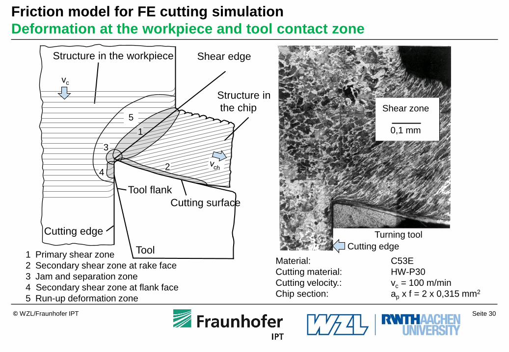
Friction model for FE cutting simulation
Deformation at the workpiece and tool contact zone
Turning tool
Shear zone
0,1 mm
Material: C53E
Cutting material: HW-P30
Cutting velocity.: vc = 100 m/min
Chip section: ap x f = 2 x 0,315 mm2
Cutting edge 1 Primary shear zone
2 Secondary shear zone at rake face
3 Jam and separation zone
4 Secondary shear zone at flank face
5 Run-up deformation zone
Structure in the workpiece
Cutting edge
Tool
Tool flank
Cutting surface
Shear edge
Structure in
the chip
2
vc
1
5
3
4

Seite 31 © WZL/Fraunhofer IPT
Friction model for FE cutting simulation
Mechanical stress at the workpiece and tool contact zone
𝜏
𝜎𝑛
𝑥
𝜏, 𝜎
Normal stress:
Shear stress:
Tool
According to Oxley and Hatton
Contact zone
1 Primary shear zone
2 Secondary shear zone at rake face
3 Jam and separation zone
4 Secondary shear zone at the flank face
5 Run-up deformation zone
Structure in the workpiece
Cutting edge
Tool
Tool flank
Cutting surface
Shear edge
Structure
in the chip
2
vc
1
5
3
4

Seite 32 © WZL/Fraunhofer IPT
kmR
NR s
Friction model for FE cutting simulation
Coulomb friction model :
Shear friction model:
with
Continuous passover from dynamic friction
(Coulomb) to static friction (shear):
Z.B.: Usui-model
τR – shear stress from friction
sN – normal stress
k – yield stress in shear according to Mises
kf – yield stress according to Mises
µ, m – friction coefficients
Coulomb friction
Shear friction
reality
Orowan / Özel
Usiu
Shaw /
Wanheim and Bay
reality
Ns
Ns
R
R
3
fkk
𝜏𝑅 = 𝑘 1 − exp(−𝜇𝜎𝑁𝑘)
Static friction Dynamic friction
Seite 33 © WZL/Fraunhofer IPT
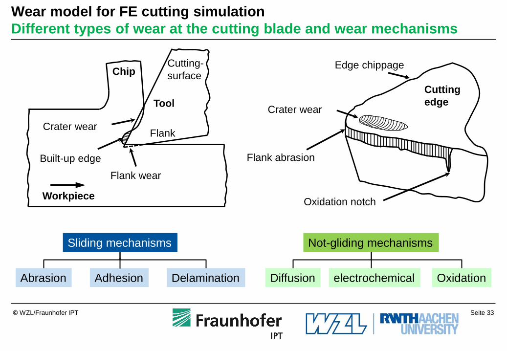
Wear model for FE cutting simulation
Different types of wear at the cutting blade and wear mechanisms
Sliding mechanisms Not-gliding mechanisms
Abrasion Adhesion Delamination Diffusion electrochemical Oxidation
Cutting
edge
Edge chippage
Crater wear
Flank abrasion
Oxidation notch
Flank wear
Crater wear
Built-up edge
Tool
Flank
Cutting-
surface
Workpiece
Chip

Seite 34 © WZL/Fraunhofer IPT
Wear model for FE cutting simulation
Tool life acc. to Taylor: Tool life acc. to Hasting:
B
AT
v
k
c CvT
T = tool life
u = temperature k, A, B = constant
Cv = T für vc = 1 m/min
Empirical tool wear
models
Physical tool wear
models
Tool wear modelling
Differential
wear models Tool life equations
Model acc. to Usui: Model acc. to Takeyama: Model acc. to Archard:
H
SFK
dt
dV
3
)T
C(
1chn
2
eCvσdt
dV
R
E
eDvGdt
dVc
dV/dt: wear-volume-rate
H: hardness
F: mechanical load
S: cutting length
K, C1, C2, G, D: constant
sn: normal stress
Vch: chip sliding speed
u: temperature
Abrasion + Diffusion Adhesion
Adhesion /
Abrasion

Seite 35 © WZL/Fraunhofer IPT
Boundary Conditions
Inter Object Conditions Environment Object Conditions Object Conditions
Tool
Workpiece
2D FEM Cutting Model
Object boundary conditions

Seite 36 © WZL/Fraunhofer IPT
Boundary Conditions
Inter Object Conditions Environment Object Conditions Object Conditions
Friction Heat Transfer
Movement Tool
=
Object 1
Workpiece = Object 2
2D FEM Cutting Model
Object boundary conditions
Seite 37 © WZL/Fraunhofer IPT
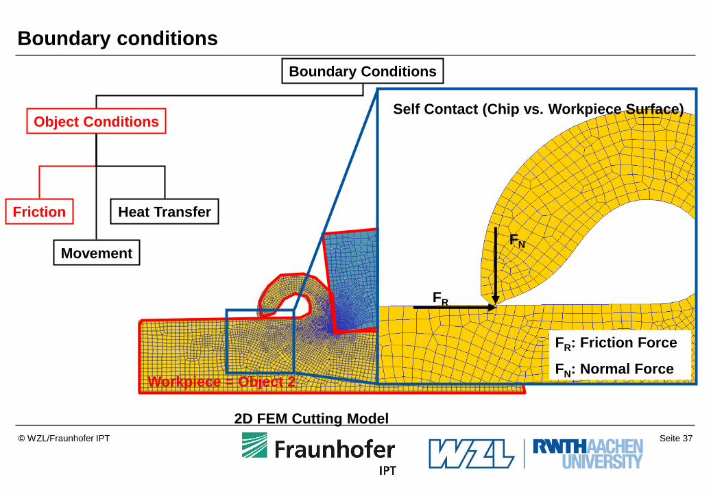
Boundary Conditions
Object Conditions
Friction Heat Transfer
Movement
Workpiece = Object 2
2D FEM Cutting Model
FR
FN
Self Contact (Chip vs. Workpiece Surface)
FR: Friction Force
FN: Normal Force
Boundary conditions

Seite 38 © WZL/Fraunhofer IPT
Boundary Conditions
Object Conditions
Friction Heat Transfer
Movement
Cutting
speed vc in
x-direction
x
y
Tool is fixed in x- and y-direction!
Tool
Workpiece
The workpiece is moving in
x-direction with the prescribed
velocity vc. It is fixed in y-direction
Object boundary conditions

Seite 39 © WZL/Fraunhofer IPT
Boundary Conditions
Object Conditions
Friction Heat Transfer
Movement
Tool
Workpiece
Heat Transfer
Object boundary conditions

Seite 40 © WZL/Fraunhofer IPT
Boundary Conditions
Inter Object Conditions Environment Object Conditions
Friction Heat Transfer
Object Conditions
Tool
Heat Transfer FR
FN
Object boundary conditions
FN
FN

Seite 41 © WZL/Fraunhofer IPT
Boundary Conditions
Inter Object Conditions Environment Object Conditions
Heat Transfer
Object Conditions
Heat Convection Heat Emissivity
Tool
Heat Radiation
Heat Convection
Heat exchange with
environment
Object boundary conditions

Seite 42 © WZL/Fraunhofer IPT
Outline
Summary and Outlook 9
Applications of the FE-cutting-simulation at the WZL 8
Criteria for the evaluation of FE software 7
Friction and wear models for the FE cutting simulation 6
Damage models for the FE cutting simulation and multiphase simulation 5
Constitutive material laws for the FE cutting simulation 4
CAD modelling for the FE cutting simulation 3
Requirements of the FE cutting simulation 2
Introduction 1

Seite 43 © WZL/Fraunhofer IPT
FEM software solution for FEM simulation of the cutting process
MSC.Marc

Seite 44 © WZL/Fraunhofer IPT
Criteria for the evaluation of FE software
Source: SIMULIA, ANSYS, LSTC, TWS, SFTC, COMSOL
Criteria
Programm ABAQUS ANSYS/ LS-DYNA AdvantEdge DEFORM COMSOL
Creation of geometries Creation of geometries
and import of CAD data
Import of CAD data
Creation of simple
geometries and
import of CAD data
Creation of simple
geometries and
import of CAD data
Creation of simple
geometries and import
of CAD data
Material catalogue No, has to be defined Yes, expandable Yes, wide Yes, new catalogue
importable
yes
Element type Every type Every type tetrahedron,
rectangle
tetrahedron, rectangle Every type
Time integration Implicit / Explicit Implicit / Explicit Explicit Implicit Implicit
Remeshing routine none none yes yes yes
use general general cuttingprocess Deforming process general
Influence on simulation
computation
High, by Python Possible, by Fortran no High, by Fortran High, by Matlab
parallelisation possible possible possible possible possible
Usage at the WZL Eigenfrequency analysis,
elast. Tool behavior,
elasto-plastic component
behavior
no no Cutting simulation Thermo-elastic
deformation

Seite 45 © WZL/Fraunhofer IPT
Outline
Summary and Outlook 9
Applications of the FE cutting simulation at the WZL 8
Criteria for the evaluation of FE software 7
Friction and wear models for the FE cutting simulation 6
Damage models for the FE cutting simulation and multiphase simulation 5
Constitutive material laws for the FE cutting simulation 4
CAD modelling for the FE cutting simulation 3
Requirements of the FE cutting simulation 2
Introduction 1

Seite 46 © WZL/Fraunhofer IPT
Applications of the FE cutting simulation at WZL
Research focus at the WZL:
Process optimization
Material modelling
Drilling Milling
2D, e.g. Planing
Turning
Seite 47 © WZL/Fraunhofer IPT
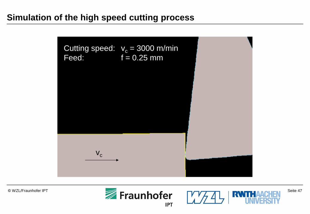
Cutting speed: vc = 3000 m/min
Feed: f = 0.25 mm
vc
Simulation of the high speed cutting process

Seite 48 © WZL/Fraunhofer IPT
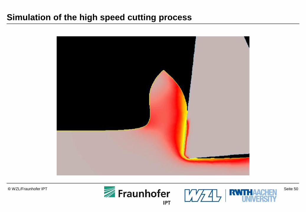
Simulation of the high speed cutting process

Seite 49 © WZL/Fraunhofer IPT
Simulation of the high speed cutting process
Seite 50 © WZL/Fraunhofer IPT
Simulation of the high speed cutting process

Seite 51 © WZL/Fraunhofer IPT
Simulation of the high speed cutting process

Seite 52 © WZL/Fraunhofer IPT
Simulation of the high speed cutting process

Seite 53 © WZL/Fraunhofer IPT
Simulation of the high speed cutting process

Seite 54 © WZL/Fraunhofer IPT
Orthogonal turning 2D (vc = 300 m/min, f = 0,1 mm, C45E)
Ceramic-Insert
Thermal conductivity l = 35 W/mK WC-Insert
Thermal conductivity l = 105 W/mK
Tmax = 650°C Tmax = 550°C
Comparison of different thermal properties of the tools
Seite 55 © WZL/Fraunhofer IPT
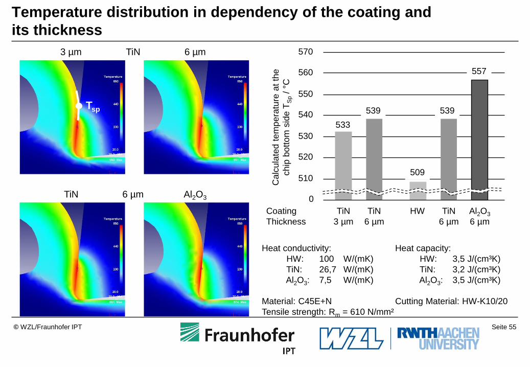
533
3 µm 6 µm
TiN Al2O3
TiN
6 µm 0
510
520
530
540
550
560
570
Ca
lcu
late
d t
em
pe
ratu
re a
t th
e
chip
bottom
sid
e T
Sp / °
C
Heat conductivity:
HW: 100 W/(mK)
TiN: 26,7 W/(mK)
Al2O3: 7,5 W/(mK)
Material: C45E+N
Tensile strength: Rm = 610 N/mm²
557
539
509
539
Heat capacity:
HW: 3,5 J/(cm³K)
TiN: 3,2 J/(cm³K)
Al2O3: 3,5 J/(cm³K)
Cutting Material: HW-K10/20
TiN
3 µm
TiN
6 µm
HW TiN
6 µm
Al2O3
6 µm
Coating
Thickness
Tsp
Temperature distribution in dependency of the coating and
its thickness
Seite 56 © WZL/Fraunhofer IPT
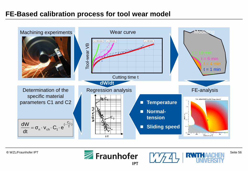
FE-Based calibration process for tool wear model
Verschleißmarkenbreite über die Schnittzeit
16MnCr5 (einsatzgehärtet), Stegbreite = 1 mm, cBN bestückte Einstechplatte der Sorte N151.2-600-50E-G
Schnittgeschwindigkeit vc = 150, 200, 300 m/min und Vorschub f = 0,06 mm
0
20
40
60
80
100
120
0 5 10 15 20 25 30 35 40
Schnittzeit t [min]
Ve
rsc
hle
ißm
ark
en
bre
ite
VB
[µ
m]
vc = 250 m/min vc = 200 m/min vc = 150 m/min
Cutting time t
To
ol-w
ear
VB
Wear curve
C2
lg C1
1/T
lg{w
/(n
VS)}
slg
{w/(
nV
S)}
sRegression analysis FE-analysis
Temperature
Normal-
tension
Sliding speed
dW/dt
Machining experiments
Determination of the
specific material
parameters C1 and C2
)T
C(
1chn
2
eCvσdt
dW
t = 1 min
t = 4 min t = 6 min
t = 10 min
Modeling

Seite 57 © WZL/Fraunhofer IPT
Ve
rsc
hle
iß V
B [
mm
]
2D FE model for tool wear simulation
Tool life

Seite 58 © WZL/Fraunhofer IPT
Phase 3: Methodology for moving the nodes at the rake face
node square element
Rake
Tool
Tool
Workpiece vc
Chip vc

Seite 59 © WZL/Fraunhofer IPT
Phase 3: Methodology for moving the nodes at the flank face
nD nA
nB nC
A B C D
nD nA nB nC = = = Workpiece
Flank
node square element
Tool 5 µm
Seite 60 © WZL/Fraunhofer IPT
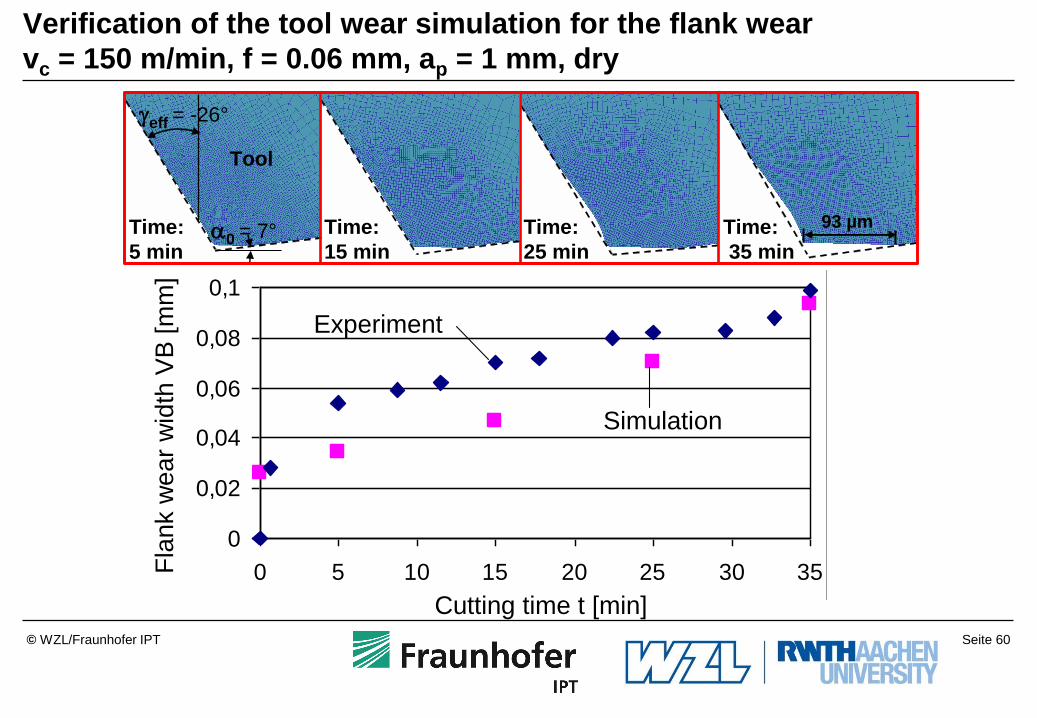
Verification of the tool wear simulation for the flank wear
vc = 150 m/min, f = 0.06 mm, ap = 1 mm, dry
0
0,02
0,04
0,06
0,08
0,1
0 5 10 15 20 25 30 35
Time [min]
Fla
nk W
ear
Wid
th V
B/
[mm
]
Experiment
Simulation
Fla
nk w
ear
wid
thV
B [
mm
]
Cutting time t [min]
eff = -26°
a0 = 7°Time:
5 min
Tool
Time:
15 min
Time:
25 min
Time:
35 min
93 µm

Seite 61 © WZL/Fraunhofer IPT
15°
7,5°
15°
Setup of a 3D FE model
Seite 62 © WZL/Fraunhofer IPT
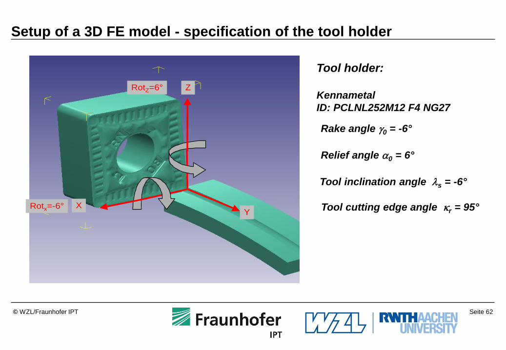
Setup of a 3D FE model - specification of the tool holder
Z
YX
RotZ=6°
Rotx=-6°
Tool holder:
Kennametal
ID: PCLNL252M12 F4 NG27
Rake angle 0 = -6°
Relief angle a0 = 6°
Tool inclination angle ls = -6°
Tool cutting edge angle r = 95°

Seite 63 © WZL/Fraunhofer IPT
f
a p
r workpiece
r tool
r tool = r workpiece
Setup of a 3D FE model - Tool position
Seite 64 © WZL/Fraunhofer IPT
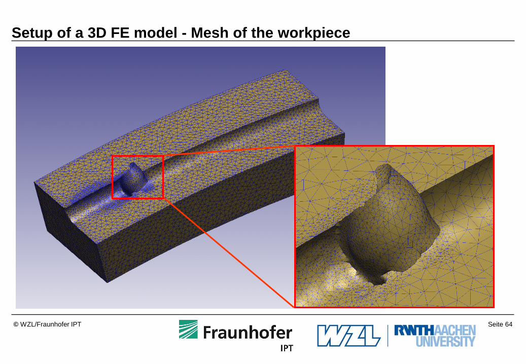
Setup of a 3D FE model - Mesh of the workpiece

Seite 65 © WZL/Fraunhofer IPT
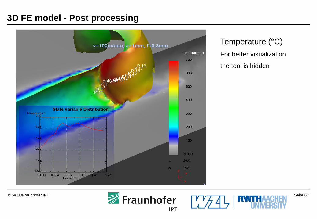
3D simulation
Workpiece: AISI 1045
Tool: K10
vc = 300 m/min
f = 0,1 mm
Cutting Force Fc
Temperature
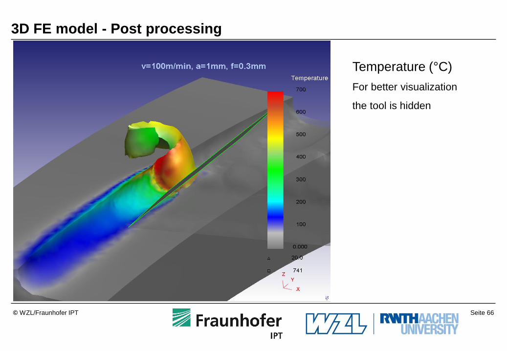
Seite 66 © WZL/Fraunhofer IPT
Temperature (°C)
For better visualization
the tool is hidden
3D FE model - Post processing
Seite 67 © WZL/Fraunhofer IPT
Temperature (°C)
For better visualization
the tool is hidden
3D FE model - Post processing

Seite 68 © WZL/Fraunhofer IPT
3D FE model - Post processing
Strain distribution
For better visualization
the tool is cut
Strain

Seite 69 © WZL/Fraunhofer IPT
3D FE model - Post processing
Strain Rate
distribution
For better visualization
the tool is cut
Strain Rate

Seite 70 © WZL/Fraunhofer IPT
Roughing geometry
CNMG120408RN
Finishing geometry
CNMG120408FN
Models of cutting inserts

Seite 71 © WZL/Fraunhofer IPT
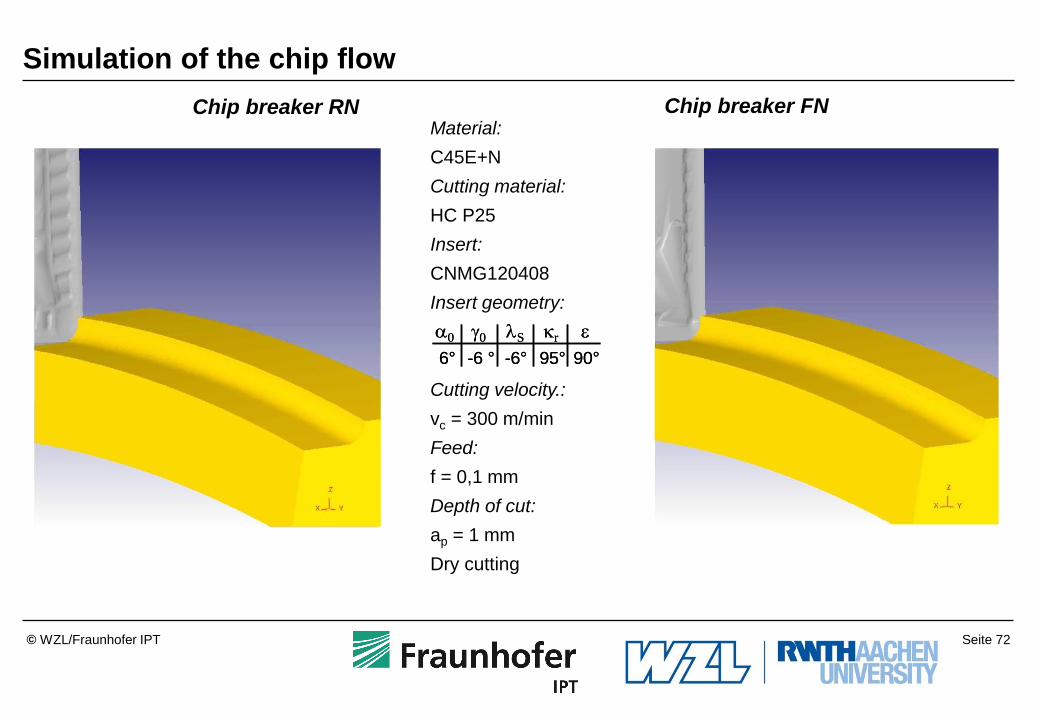
Simulation of the chip flow
Material:
C45E+N
Cutting material:
HC P25
Insert:
CNMG120408
Insert geometry:
Cutting velocity.:
vc = 300 m/min
Feed:
f = 0,1 mm
Depth of cut:
ap = 1 mm
Dry cutting
Chip breaker FN Chip breaker RN
a0 0 lS r
6° -6 ° 95°-6°
90°
a0 0 lS r
6° -6 ° 95°-6°
90°
Seite 72 © WZL/Fraunhofer IPT
Simulation of the chip flow
a0 0 lS r
6° -6 ° 95°-6°
90°
a0 0 lS r
6° -6 ° 95°-6°
90°
Chip breaker FN Chip breaker RN Material:
C45E+N
Cutting material:
HC P25
Insert:
CNMG120408
Insert geometry:
Cutting velocity.:
vc = 300 m/min
Feed:
f = 0,1 mm
Depth of cut:
ap = 1 mm
Dry cutting

Seite 73 © WZL/Fraunhofer IPT
Comparison of simulation and real chip flow
CNMG120408
Chip breaker NF
HC-P15
r = 95°
n = -6°
ls = -6°
C45E+N
ap = 1,9 mm
f = 0,25 mm
vc = 200 m/min
dry
vc vf

Seite 74 © WZL/Fraunhofer IPT
Drilling: Modelling of size effects
Task:
Development of a consistent 3D computation model based on the FE method
for scaling the drilling process in consideration of size effects
Reibung
Werkstück
Bohrwerkzeug
Plastische
Verformung
Stofftrennung
Reibung
f
n
drill
Friction Friction
Workpiece
Separation of material Plastic
deformation

Seite 75 © WZL/Fraunhofer IPT
Previous results: 3D FE computation model for d = 1 – 10 mm
Material modeling Measuring the drill geometry FE boundary conditions
Tool FEM-Model )T,,( ss
Strain hardening
Plasticity
Damping mechanism
Relaxation
Dynamic strain ageing
Temperature influence
Loss of cohesion
Failure mechanism
Cutting parameters
Tool: rigid / elastic
Friction law
Heat transfer
Element size
Number of elements
Remeshing strategy
Degree of freedom
Seite 76 © WZL/Fraunhofer IPT
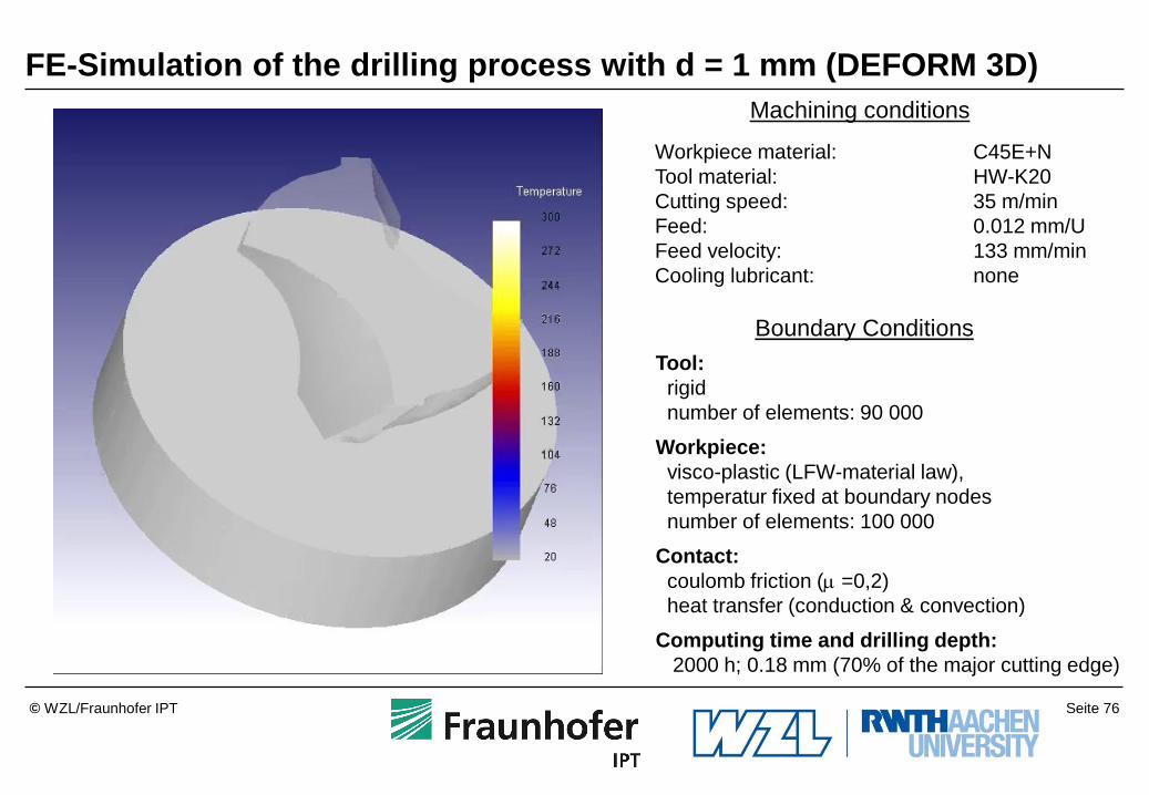
FE-Simulation of the drilling process with d = 1 mm (DEFORM 3D)
Tool:
rigid
number of elements: 90 000
Workpiece:
visco-plastic (LFW-material law),
temperatur fixed at boundary nodes
number of elements: 100 000
Contact:
coulomb friction ( =0,2)
heat transfer (conduction & convection)
Computing time and drilling depth:
2000 h; 0.18 mm (70% of the major cutting edge)
Boundary Conditions
Machining conditions
Workpiece material: C45E+N
Tool material: HW-K20
Cutting speed: 35 m/min
Feed: 0.012 mm/U
Feed velocity: 133 mm/min
Cooling lubricant: none

Seite 77 © WZL/Fraunhofer IPT
Verification of the chip formation
Experimental chip formation Chip formation in the simulation
Workpiece material: C45E+N
Cutting tool material: HW K20
Cutting speed:
Feed:
vc = 35 m/min
f = 0.012 mm

Seite 78 © WZL/Fraunhofer IPT
Model validation: Scaling effect of the chisel edge length
0
1
2
3
4
5
6
1 2 3 4 5 6 7 8 9 10
kf,max
= 2 * Fz,max
/ (d * f)
Bohrerdurchmesser d [mm]
sp
ezifis
ch
e V
ors
chub
kra
ft k
f,m
ax [kN
/mm
2]
0
1
2
3
4
5
6
1 2 3 4 5 6 7 8 9 10
k
f,max = 2 * F
z,max / (d * f)
Bohrerdurchmesser d [mm]
sp
ezifis
ch
e V
ors
chub
kra
ft k
f,m
ax [kN
/mm
2]
Experiment
20
22
24
26
28
30
32
1 2 3 4 5 6 7 8 9 10
Durchmesser d [mm]
Ve
rhä
ltnis
(d
Q / d
) [
%]
Feed:
f = 0,012 * d
Cutting speed:
vc = 35 m/min
Corner radius:
rn = 4 µm
Cutting tool material:
HW-K20
Workpiece:
C45E+N
Cooling:
None
Simulation
Diameter d [mm]
Sp
ecific
fe
ed
fo
rce
kf,
max [kN
/mm
2]
Drill diameter d [mm]

Seite 79 © WZL/Fraunhofer IPT
Model validation: Temperature at the main cutting edge (center)
Cutting speed: vc = 35 m/min Workpiece: C45E+N
Feed: f = 0,012 * d Cutting tool material:HW-K20
Coolant: None Rounding: rn = 4 µm
d = 3 mm
0
100
200
300
400
1 3 8 10
Diameter d [mm]
Te
mp
era
ture
at th
e
ma
jor
cu
ttin
g e
dg
e T
[°C
]
Experiment
Simulation

Seite 80 © WZL/Fraunhofer IPT
Modelling of the face milling process
Materials and cutting parameters:
Work material: Quenched and tempered AISI 1045 (normalized)
Tool material: Coated WC
Cutting parameters:
– No. of teeth: z = 4
– Diameter: D = 32 mm
– Engagement angle: φA – φE = 180°
– Feed: f = 0.5 mm
– Feed per tooth: fZ = 0.125 mm
– Depth of cut: ap = 0.8 mm
– Tool leading angle: κr = 90°
– Tool inclination angle: λ = -5°
– No. of rev.: n = 2250 min-1
p a
z
Workpiece
Tool
r
n
f
f v

Seite 81 © WZL/Fraunhofer IPT
Modelling of the face milling process
Axial and radial rake angle:
Axial rake angle γaxial = 9°
Radial rake angle γradial = 5°
γaxial
Seite 82 © WZL/Fraunhofer IPT
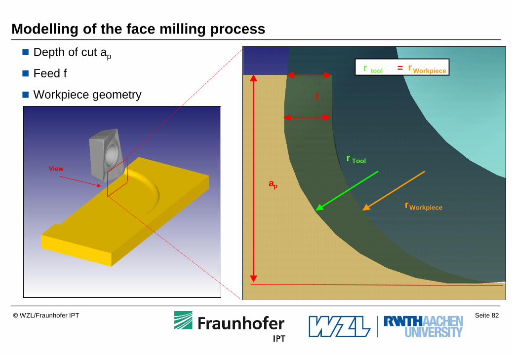
f
a p
r Workpiece
r Tool
r tool = r Workpiece
View
Depth of cut ap
Feed f
Workpiece geometry
Modelling of the face milling process

Seite 83 © WZL/Fraunhofer IPT
1 2
1. Simplified
workpiece
geometry
2. Simplified work-
piece geometry
3. Simplified work-
piece geometry
Finding the best workpiece geometry

Seite 84 © WZL/Fraunhofer IPT
back
Simulation results for the 1. simplified workpiece model
Rough elements within the
work piece
Simulation of chip formation
not accurate enough

Seite 85 © WZL/Fraunhofer IPT
Final workpiece geometry
Left Right
Simulation results for the 3. simplified workpiece model

Seite 86 © WZL/Fraunhofer IPT
Chip formation for the left
side of the work piece:
Results for the face milling operation
at the beginning very thin
chips are produced
chip curling starts for higher
undeformed chip thickness

Seite 87 © WZL/Fraunhofer IPT
.
Full agreement
Experiment Simulation
Verification of the FE model

Seite 88 © WZL/Fraunhofer IPT
FE based sensitivity analysis
Thermal
conductivity
Heat
capacity
Flow
stress
Cutting force
Feed force
Passive force
Temperature
Friction Tool
micro-geometry
Heat capacity
Thermal conductivity
Flow stress
Friction coefficient
Tool micro-geometry
Varied input
parameters:
Goal output
parameters: Cutting force Fc
Passive force Fp
Feed force Ff
Temperature T
Influence
low
medium
high
Legend

Seite 89 © WZL/Fraunhofer IPT
Outline
Summary and Outlook 9
Applications of the FE cutting simulation at the WZL 8
Criteria for the evaluation of FE software 7
Friction and wear models for the FE cutting simulation 6
Damage models for the FE cutting simulation and multiphase simulation 5
Constitutive material laws for the FE cutting simulation 4
CAD modelling for the FE cutting simulation 3
Requirements of the FE cutting simulation 2
Introduction 1

Seite 90 © WZL/Fraunhofer IPT
#
Cutting
simulation
Determination of the
thermomechanical
loadspectrum, chip
flow, chip form
Q,
T,
Fi,
Fixed input
parameter material parameter,
friction coefficients
+
Temp Wear Stress Chip
flow
Tool A + - ++ -
Tool B - -- o +
Tool C ++ ++ + +
A B C
Tool
Benchmark-Analysis
Fla
nk w
ear
VB
Cutting parameter 1
Cutting parameter 2
Optimised
tool-
and
tool carrier-
geometry
Tool +
A B C
Cutting parameter
vc1, ap1, f1
1
vc2, ap1, f1
2
Outlook:
Benchmark-Analysis to choose the best tool geometry
Coating +
TiN TiAlN AlO2
Seite 91 © WZL/Fraunhofer IPT
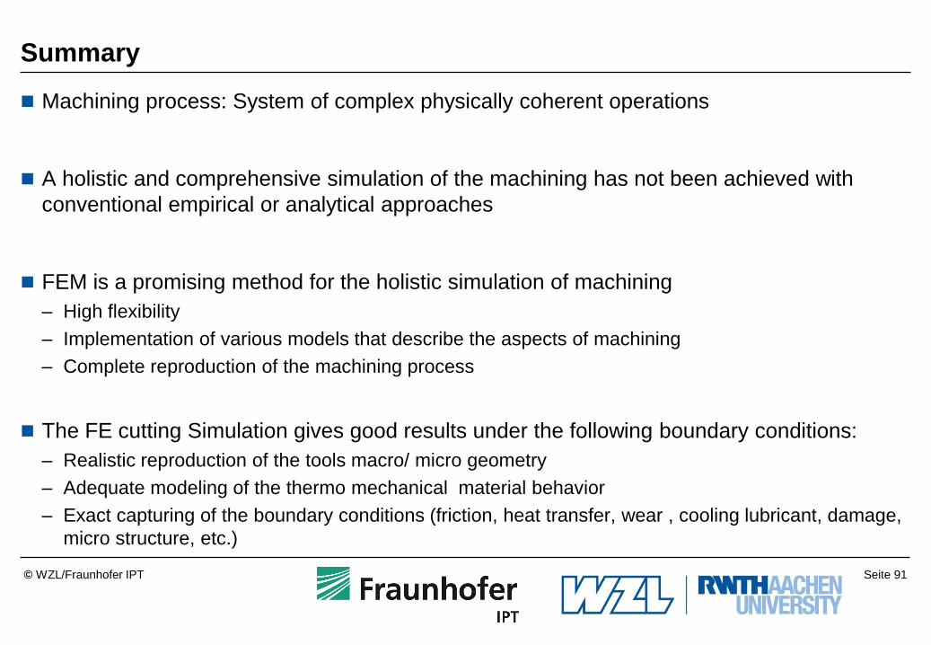
Summary
Machining process: System of complex physically coherent operations
A holistic and comprehensive simulation of the machining has not been achieved with
conventional empirical or analytical approaches
FEM is a promising method for the holistic simulation of machining
– High flexibility
– Implementation of various models that describe the aspects of machining
– Complete reproduction of the machining process
The FE cutting Simulation gives good results under the following boundary conditions:
– Realistic reproduction of the tools macro/ micro geometry
– Adequate modeling of the thermo mechanical material behavior
– Exact capturing of the boundary conditions (friction, heat transfer, wear , cooling lubricant, damage,
micro structure, etc.)
Seite 92 © WZL/Fraunhofer IPT
Questions
What are the ranges of temperature, strain and strain rate in cutting operations?
What is the range of strain rate, that can be realized by the Split-Hopkinson-Bar-Test?
Name two friction models. What are the advantages and the disadvantgeas of these
models?
How is the strain rate effecting the flow stress curve of a material?
What are the demands on a temperature measurement setup which allows the evaluation
of simulation results?
Explain the difference between the orthogonal cutting process and the longitudinal cutting
process!
Explain the difference between a plastic and an elastic-plastic flow stress curve!